Loading ...
Loading ...
Loading ...
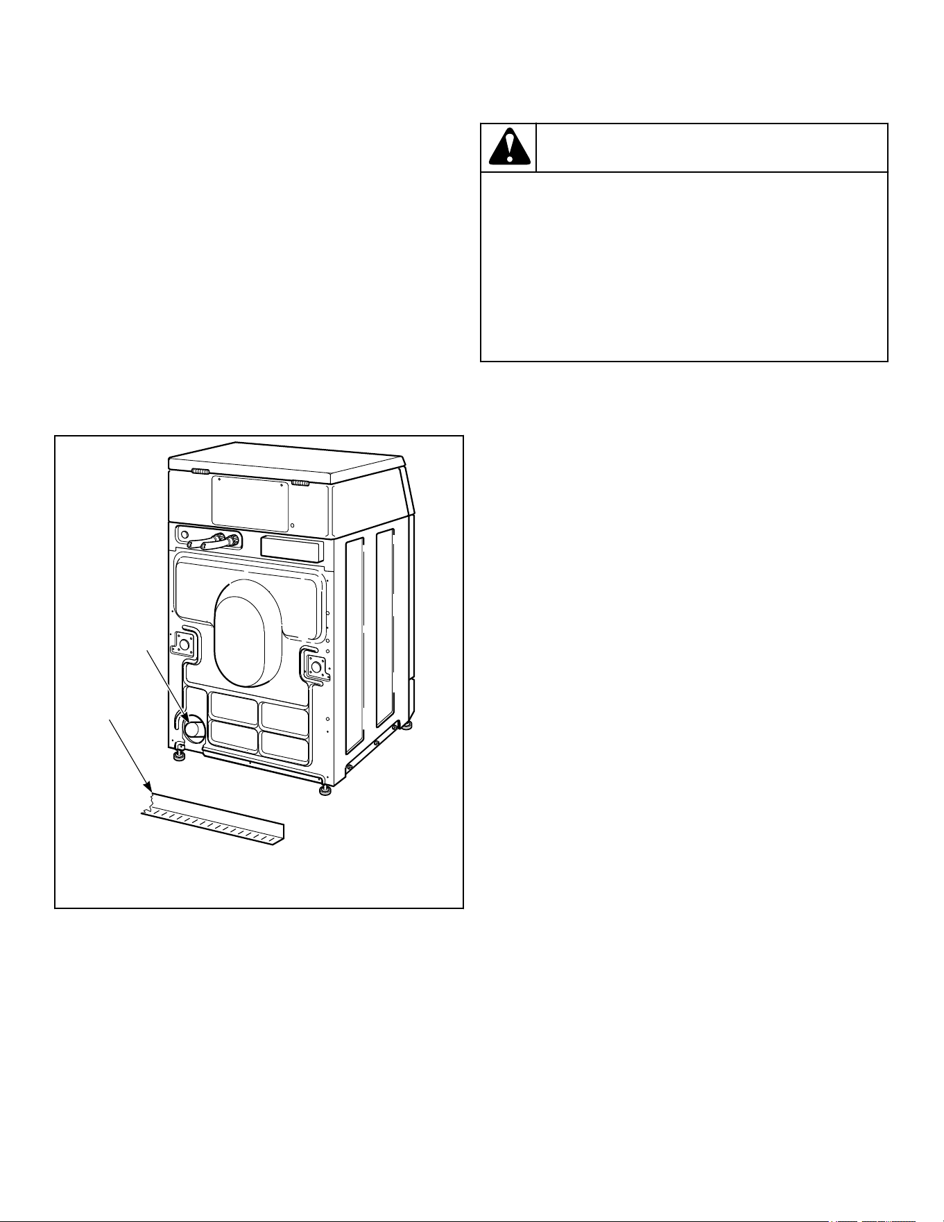
Gravity Drain Models - Connect Drain
Outlet to Drain System
Maximum flow rate is 24 gallons/minute [90.8 liters/minute].
Flow rates will vary with load type.
1. Remove drain fitting (4 inches [102 mm] long) and hose
clamp from accessories bag. Insert drain fitting into drain out-
let hose. Clamp hose and fitting.
2. Connect the drain fitting to a vented drain system using a
flexible connection (obtain locally). Inside diameter of fitting
is 1.53 in. [39 mm] and outside diameter is 1.66 in. [42 mm].
3. The drain system must be vented to prevent an air lock or si-
phoning.
IMPORTANT: Increasing the drain hose length, in-
stalling elbows, or causing bends will decrease
drain flow rates and increase drain times, impairing
machine performance.
FLW2339N_SVG
1
2
1. Drain Trough
2. Drain Outlet Hose
Figure 10
Position and Level the Washer
WARNING
Washers elevated above floor level must be anch-
ored to that elevated surface, base or platform. The
material used to elevate the washer should also be
anchored to the floor to ensure that the washer will
not walk or that the washer can not be physically
pulled, tipped or slid from its installed position. Fail-
ure to do so may result in conditions which can pro-
duce serious injury, death and/or property damage.
W306
1. Position unit so it has sufficient clearance for installation and
servicing.
NOTE: Use of the dispenser drawer or washer door
as a handle in the transportation of the washer may
cause damage to the dispenser or door.
2. Place unit in position on a solid, sturdy and level floor. Instal-
ling the unit on any type of carpeting, soft tile or other weakly
supported structures is not recommended.
3. Place a level on the raised portion of cabinet top and check if
the unit is level from side to side and front to back.
4. If unit is not level, tilt unit to access the front and rear level-
ing legs. For easier access to leveling legs, prop up unit with a
wooden block.
5. Loosen 7/8 in. locknut and adjust legs by screwing into or out
of unit base until the unit is level from side to side and front
to back (using a level). Unit should not rock.
NOTE: Leveling legs can also be adjusted from in-
side the unit using an adjustable wrench.
6. Tighten the locknuts securely against the unit base. If the
locknuts are not tight, unit will move out of position during
operation.
NOTE: DO NOT slide unit across floor if the leveling
legs have been extended. Legs and base could be-
come damaged.
7. Remove rubber feet from accessories bag and place on all
four leveling legs.
8. Verify that unit doesn’t rock.
Installation
©
Copyright, Alliance Laundry Systems LLC -
DO NOT COPY or TRANSMIT
14 Part No. 805414ENR2
Loading ...
Loading ...
Loading ...