
181989 Rev. 2 10.08.02 BY Printed in U.S.A.
Model No.
944.362310
CAUTION:
Read and follow all
Safety Rules and In struc tions
before operating this equipment
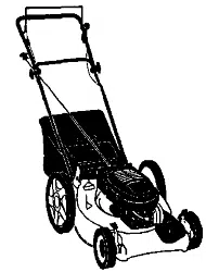
Owner’s Manual
ROTARY LAWN MOWER
6.5 Horsepower
Power-Propelled
21" Rear Discharge
Sears Canada, Inc., Toronto, Ontario M5B 2B8

2
Warranty .................................................. 2
Safety Rules ......................................... 2-4
Assembly/Pre-Operation ......................... 4
Operation.............................................. 5-8
Maintenance Schedule............................ 9
Maintenance....................................... 9-12
Product Spec i fi ca tions ......................... 10
Service and Adjustments.................. 12-13
Storage............................................. 14-15
Troubleshooting ................................ 15-16
Repair Parts...................................... 17-26
Sears Service .......................... Back Cover
TABLE OF CONTENTS
SAFETY RULES
I. GENERAL OPERATION
• Read, understand, and follow all
in struc tions on the machine and in the
manual(s) before starting. Be thor ough ly
familiar with the controls and the proper
use of the machine before starting.
• Do not put hands or feet near or under
rotating parts. Keep clear of the dis-
charge opening at all times.
• Only allow responsible individuals, who
are familiar with the in struc tions, to
operate the machine.
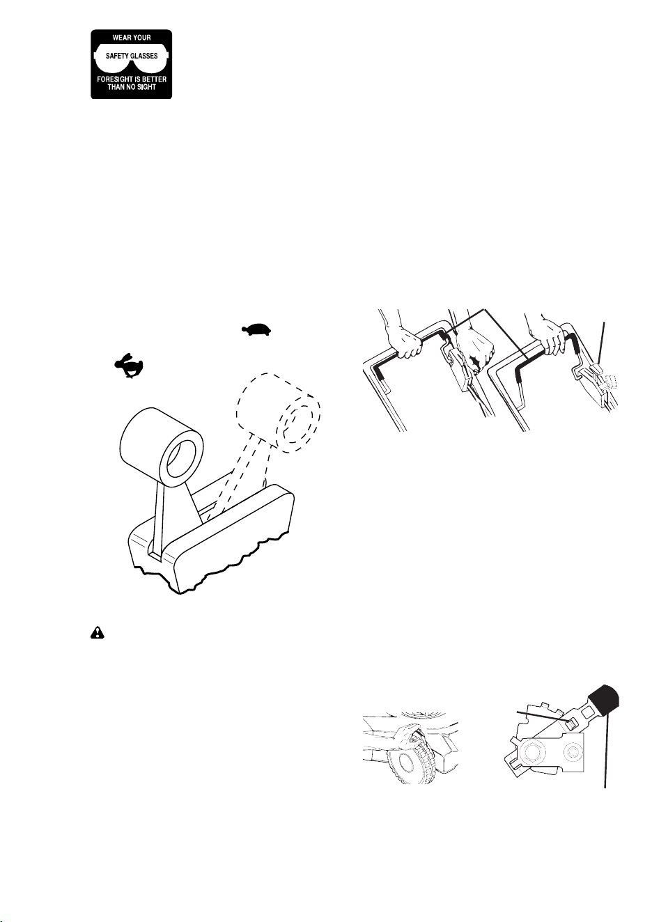
• Clear the area of objects such as rocks,
toys, wire, bones, sticks, etc., which
could be picked up and thrown by the
blade.
• Be sure the area is clear of other people
before mowing. Stop ma chine if anyone
enters the area.
IMPORTANT: This cutting machine is capable of amputating hands and feet and throwing ob-
jects. Failure to observe the following safety instructions could result in serious injury or death.
Look for this symbol to point out
im por tant safety precautions. It means
CAU TION!!! BECOME ALERT!!! YOUR
SAFE TY IS INVOLVED.
CAUTION: Always disconnect spark
plug wire and place wire where it cannot
contact spark plug in order to prevent
ac ci den tal starting when setting up,
trans port ing, adjusting or making repairs.
CAUTION: Muffl er and other engine
parts become extremely hot during
operation and remain hot after engine has
stopped. To avoid severe burns on contact,
stay away from these areas.
LIMITED TWO YEAR WARRANTY ON CRAFTSMAN POWER MOWER
For Two years from date of purchase Sears Canada, Inc. will repair or replace at Sears
option free of charge parts which are defective as a result of material or workmanship.
COMMERCIAL OR RENTAL USE:
Warranty on Power Mower (Gas) will be ninety (90) days from date of purchase if used
for commercial or rental purposes.
This Warranty does NOT
cover:
• Pre-delivery set-up.
• Expendable items which become worn during normal use, such as rotary mower
blades, blade adapters, belts, air clean ers and spark plug.
• Repairs necessary because of operator abuse or neg li gence, including bent crank-
shafts and the failure to main tain the equip ment according to the instructions con tained
in the owner’s manual.
Warranty service is available by returning the Craftsman Power Mower to the nearest
Sears Service Centre/Department in Canada. This warranty applies only while this prod-
uct is used in Canada.
This warranty is in addition to any statutory warranty and does not exclude or limit legal
rights you may have but shall run con cur rent ly with applicable provincial legislation. Fur-
thermore, some provinces do NOT allow limitation on how long an implied warranty will
last so the above limitations may not apply to you.
SEARS CANADA, INC., TORONTO, ONTARIO M5B 2B8
WARRANTY
27
SERVICE NOTES

26
MODEL NUMBER 123K02-0183-E1
BRIGGS & STRATTON 4-CYCLE ENGINE
KEY PART
NO. NO. DESCRIPTION
29 499424 Rod, Connecting
32 691664 Screw, Connecting Rod
32A 695759 Screw, Connecting Rod
33 262651 Valve, Exhaust
34 262652 Valve, Intake
35 691270 Spring, Valve, Intake
36 691270 Spring, Valve, Exhaust
37 694086 Guard, Flywheel
40 692194 Retainer, Valve
43 691997 Slinger, Governor/Oil
45 690548 Tappet, Valve
46 691449 Camshaft
48 498826 Short Block (Replacement Engine,
Model Number 123K02-0015-E1)
50 497465 Manifold, Intake
51 272199 • Gasket, Intake
54 691650 Screw, Intake Manifold
55 691421 Housing, Rewind Starter
58 692259 Rope, Starter (Cut to Length)
60 281434 Grip, Starter Rope
65 690837 Screw, Rewind Starter
78 691108 Screw, Flywheel Guard
81 691740 Lock, Muffl er Screw
95 691636 Screw, Throttle Valve
97 696565 Shaft, Throttle
104 691242 Ø Pin, Float Hinge
117 498978 Jet, Main, Standard
118 497466 Jet, Main, High Altitude
121 498260 Kit, Carburetor Overhaul
125 498170 Carburetor
127 694468 Ø Plug, Welch
130 696564 Valve, Throttle
133 398187 Float, Carburetor
134 398188 Ø Valve, Needle/Seat
137 693981 ؇ Gasket-Float Bowl
146 690979 Key, Timing
159 691753 Bracket, Air Cleaner Primer
163 272653 •Ø‡ Gasket, Air Cleaner
187 691050 Line,Fuel (Cut to Required Length)
188 693399 Screw, Control Bracket
190 690940 Screw, Fuel Tank
202 691829 Link, Mechanical Governor
209 690319 Spring, Governor
222 692031 Bracket, Control
227 690783 Control Lever-Governor
276 271716 ؇ Sealing Washer
287 690940 Screw (Dipstick Tube
300 692038 Muffl er
304 695892 Housing, Blower
305 691108 Screw, Blower Housing
306 690450 Shield, Cylinder
307 690345 Screw, Cylinder Shield
332 690662 Nut, Flywheel
333 802574 Armature, Magneto
334 691061 Screw, Armature
337 802592 Spark Plug
356 692390 Wire, Stop
358 497316 Engine Gasket Set
363 19069 Flywheel Puller
365 692524 Screw, Carburetor
383 89838 Wrench, Spark Plug
404 690272 Washer, Governor Crank
425 690670 Screw, Air Cleaner Cover
443 692523 Screw, Air Cleaner Primer Base
445 491588 Filter, Air Cleaner Cartridge
KEY PART
NO. NO. DESCRIPTION
455 691219 Cup, Flywheel
456 692299 Plate, Pawl Friction
459 281505 Pawl, Ratchet
505 231082 Nut, Governor Control Lever
523 495264 Dipstick
524 692296 • Seal, Dipstick Tube
525 495265 Tube, Dipstick
529 691923 Grommet
562 92613 Bolt, Governor Control Lever
584 692342 Cover, Breather Passage
585 691879 • Gasket, Breather Passage
592 690800 Nut, Rewind Starter
597 691696 Screw, Pawl Friction Plate
601 95162 Clamp, Hose
608 497680 Starter, Rewind
613 691340 Screw, Muffl er
615 690340 Retainer, Governor Shaft
616 691308 Crank, Governor
617 270344 •Ø‡ Seal, O-Ring, Intake Manifold
621 692310 Switch, Stop
633 691321 ؇ Seal, Throttle Shaft
635 66538 Boot, Spark Plug
668 493823 • Spacer (Includes 2)
670 692294 Spacer, Fuel Tank
684 690345 Screw, Breather Passage Cover
689 691855 Spring, Friction
718 690959 Pin, Locating
741 691830 Gear, Timing
745 691648 Screw, Brake
842 691031 • Seal, O-Ring, Dipstick Tube
847 692017 Assembly, Dipstick/Tube
851 493880 Terminal, Spark Plug
868 697338 Seal, Valve
869 691155 Seat, Valve, Intake
870 690380 Seat, Valve, Exhaust
871 262001 Bushing, Guide, Exhaust
63709 Bushing, Guide, Intake
921 697343 Cover, Blower Housing
922 692135 Spring, Brake
923 695891 Brake
957 397974 Cap, Fuel Tank
966 496116 Base, Air Cleaner Primer
968 692298 Cover, Air Cleaner
969 690700 Screw, Blower Housing Cover
970 691669 Screw, Air Cleaner Primer Bracket
972 495224 Tank, Fuel
975 493640 Bowl, Float
976 694395 Primer, Carburetor
977 498261 Set, Carburetor Gasket
1019 494256 Kit, Label
1036 697456 Label, Emissions
1059 692311 Kit, Screw/Washer
1210 498144 Assembly, Pulley/Spring (Pulley)
1211 498144 Assembly, Pulley/Spring (Spring)
RPM Settings: Low Speed: 1900-2100
High Speed: 3000-3200
• Included in Engine Gasket Set, Key #358
Ø Included in Carburetor Overhaul Kit, Key #121
‡ Included in Carburetor Gasket Set, Key #977
NOTE: All component dimensions given in U.S. inches
1 inch = 25.4 mm
3
• Do not operate the mower when bare-
foot or wearing open sandals. Al ways
wear substantial foot wear.
• Do not pull mower backwards unless abso-
lutely nec es sary. Always look down and be-
hind before and while moving backwards.
• Do not operate the mower without
proper guards, plates, grass catcher or
oth er safety protective devices in place.
• See manufacturer’s instructions for
proper operation and installation of
accessories. Only use accessories ap-
proved by the manufacturer.
• Stop the blade(s) when crossing grav el
drives, walks, or roads.
• Stop the engine (motor) whenever you
leave the equip ment, before clean ing
the mower or unclogging the chute.
• Shut the engine (motor) off and wait
until the blade comes to complete stop
before removing grass catcher.
• Mow only in daylight or good artifi cial light.
• Do not operate the machine while under
the infl uence of alcohol or drugs.
• Never operate machine in wet grass. Al-
ways be sure of your footing: keep a fi rm
hold on the handle and walk; never run.
• Disengage the self-propelled mech a nism
or drive clutch on mowers so equipped
before starting the engine (motor).
• If the equipment should start to vi brate
abnormally, stop the engine (motor) and
check immediately for the cause. Vibra-
tion is generally a warning of trouble.
• Always wear safety goggles or safe ty glass-
es with side shields when op er at ing mower.
II. SLOPE OPERATION
Slopes are a major factor related to slip
and fall accidents which can result in
severe injury. All slopes require extra cau-
tion. If you feel uneasy on a slope, do not
mow it.
• Mow across the face of slopes: nev er
up and down. Exercise extreme caution
when changing direction on slopes.
• Remove obstacles such as rocks, tree
limbs, etc.
• Watch for holes, ruts, or bumps. Tall
grass can hide obstacles.
DO NOT:
• Do not trim near drop-offs, ditches or
embankments. The operator could lose
footing or balance.
• Do not trim excessively steep slopes.
• Do not mow on wet grass. Reduced
footing could cause slipping.
III. CHILDREN
Tragic accidents can occur if the op er a tor is
not alert to the presence of children. Children
are often attracted to the ma chine and the
mowing activity.
Never
assume that children
will remain where you last saw them.
• Keep children out of the trimming area
and under the watchful care of an oth er
re spon si ble adult.
• Be alert and turn machine off if chil dren
enter the area.
• Before and while walking back wards,
look behind and
down
for small chil dren.
• Never allow children to operate the machine.
• Use extra care when approaching blind
corners, shrubs, trees, or other objects
that may obscure vision.
IV. SERVICE
• Use extra care in handling gasoline and
other fuels. They are fl ammable and
vapors are explosive.
- Use only an approved container.
- Never remove gas cap or add fuel
with the engine running. Allow engine
to cool before refueling. Do not smoke.
- Never refuel the machine indoors.
- Never store the machine or fuel
container inside where there is an
open fl ame, such as a water heater.
• Never run a machine inside a closed area.
• Never make adjustments or repairs with
the engine (motor) running. Dis con nect the
spark plug wire, and keep the wire away
from the plug to prevent ac ci den tal starting.
• Keep nuts and bolts, especially blade
attachment bolts, tight and keep equip-
ment in good condition.
• Never tamper with safety devices. Check
their proper operation regularly.
• Keep machine free of grass, leaves, or
other debris build-up. Clean oil or fuel spill-
age. Allow machine to cool before storing.
• Stop and inspect the equipment if you
strike an object. Repair, if nec es sary,
before restarting.
• Never attempt to make wheel height adjust-
ments while the engine (mo tor) is running.
• Grass catcher components are sub ject
to wear, dam age, and de te ri o ra tion,
which could expose moving parts or
allow objects to be thrown. Frequently
check com po nents and replace with
man u fac tur er’s recommended parts,
when necessary.
• Mower blades are sharp and can cut.
Wrap the blade(s) or wear gloves, and
use extra caution when ser vic ing them.
• Do not change the engine governor set-
ting or overspeed the engine.
4
ASSEMBLY / PRE-OPERATION
Read these instructions and this manual in
its entirety before you attempt to assemble
or operate your new lawn mower.
IMPORTANT: This lawn mower is shipped
WITHOUT OIL OR GASOLINE in the engine.
Your new lawn mower has been as sem -
bled at the factory with the exception of
those parts left unassembled for shipping
purposes. All parts such as nuts, wash-
ers, bolts, etc., nec es sary to complete the
as sem bly have been placed in the parts
bag. To ensure safe and proper opera-
tion of your lawn mower, all parts and
hard ware you assemble must be tightened
securely. Use the correct tools as neces-
sary to ensure proper tightness.
TO REMOVE LAWN MOWER FROM
CAR TON
1. Remove loose parts included with mower.
2. Cut down two end corners of carton
and lay end panel down fl at.
3. Remove all packing materials except
padding between upper and lower
handle and padding holding operator
presence control bar to upper handle.
4. Roll lawn mower out of carton and
check carton thor ough ly for additional
loose parts.
HOW TO SET UP YOUR LAWN
MOW ER
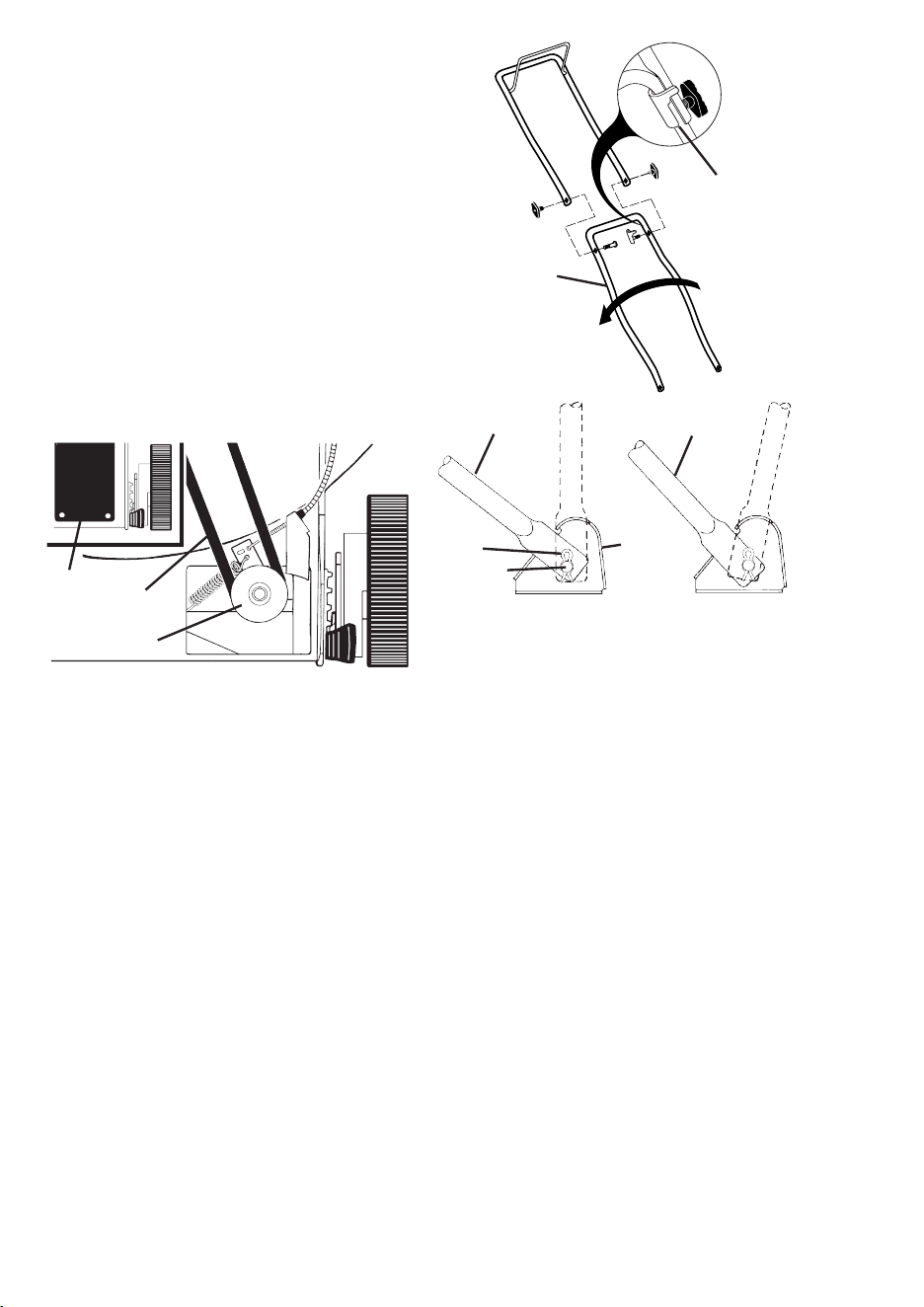
TO UNFOLD HANDLE
IMPORTANT: Unfold handle carefully so
as not to pinch or damage con trol cables.
1. Raise handles until lower handle sec-
tion locks into place in mowing position.
2. Remove protective padding, raise up-
per handle sec tion into place on lower
handle and tighten both handle knobs.
3. Remove handle padding holding opera-
tor pres ence control bar to upper handle.
Your lawn mower handle can be adjusted
for your mowing comfort. Refer to “AD-
JUST HANDLE” in the Service and Adjust-
ments section of this manual.
TO ASSEMBLE GRASS CATCH ER
1. Put grass catcher frame into grass bag
with rigid part of bag on the bottom.
Make sure the frame handle is outside
of the bag top.
2. Slip vinyl bindings over frame.
NOTE: If vinyl bindings are too stiff, hold
them in warm water for a few minutes. If
bag gets wet, let it dry before using.
TO INSTALL ATTACHMENTS
Your lawn mower was shipped ready to be
used as a mulcher. To convert to bag-
ging, see “TO CON VERT MOW ER” in the
Operation section of this man u al.
Mowing
position
Lower handle
LIFT
UP
Operator presence
control bar
Upper handle
LIFT UP
Catcher
frame
handle
Vinyl
bindings
Frame
opening
25
MODEL NUMBER 123K02-0183-E1
BRIGGS & STRATTON 4-CYCLE ENGINE
334
851
333
202
209
356
562
505
227
616
404
615
922
621
923
358 ENGINE GASKET SET
12
3
20
51
585
7
163
524
668
842
48
617
745
KEY PART
NO. NO. DESCRIPTION
1 697322 Cylinder Assembly
2 399269 Kit, Bushing/Seal
3 299819 • Seal, Oil, Magneto Side
4 493279 Sump, Engine
5 691160 Head, Cylinder
7 692249 • Gasket, Cylinder Head
8 695250 Breather Assembly
9 696125 Gasket, Breather
10 691125 Screw, Breather Assembly
11 691781 Tube, Breather
12 692232 • Gasket, Crankcase
13 690912 Screw, Cylinder Head
15 691680 Plug, Oil Drain
16 691451 Crankshaft
KEY PART
NO. NO. DESCRIPTION
20 399781 • Seal, Oil, PTO Side
22 691092 Screw, Engine Sump
23 692315 Flywheel
24 222698 Key, Flywheel
25 697339 Piston Assembly, Standard
697340 Piston Assembly, .010" Oversize
697341 Piston Assembly, .020" Oversize
697342 Piston Assembly, .030" Oversize
26 499425 Ring Set, Piston, Standard
499426 Ring Set, Piston, .010" Oversize
499427 Ring Set, Piston, .020" Oversize
499428 Ring Set, Piston, .030" Oversize
27 691866 Lock, Piston Pin
28 499423 Pin, Piston
24
MODEL NUMBER 123K02-0183-E1
BRIGGS & STRATTON 4-CYCLE ENGINE
332
304
305
363
455
23
1036 EMISSIONS LABEL
55
456
58
60
459
689
597
608
65
592
921
969
190
670
957
972
1059
601
187
1211
1210
78
37
5
OPERATION
KNOW YOUR LAWN MOWER
READ THIS OWNER'S MANUAL AND ALL SAFETY RULES BEFORE OPERATING YOUR
LAWN MOWER. Compare the illustrations with your lawn mower to familiarize yourself with
the location of various controls and adjustments. Save this manual for future reference.
Starter
handle
Gasoline
fi ller cap
Housing
Wheel adjuster (on each wheel)
Handle knob
Grass
catcher
Engine oil cap
with dipstick
Operator presence control bar
Primer
MEETS CPSC SAFETY REQUIREMENTS
Sears rotary walk-behind power lawn mowers conform to the safety standards of the
American National Standards Institute and the U.S. Consumer Product Safety Com-
mis sion. The blade turns when the engine is running.
Operator presence control bar – must
be held down to the handle to start the
engine. Release to stop the engine.
Primer – pumps additional fuel from the
carburetor to the cylinder for use when
starting a cold engine.
Starter handle – used for starting engine.
These symbols may appear on your lawn mower or in literature supplied with the product.
Learn and understand their meaning.
IMPORTANT: This lawn mower
is shipped WITHOUT OIL OR
GASOLINE in the engine.
Drive control lever – used to engage
power-pro pelled forward mo tion of lawn
mower.
Throttle control – used for start ing the
engine and allows you to select either
FAST or SLOW engine speed.
Muffl er
Air fi lter
Drive control lever
Drive cover
Throttle
control
6
The operation of any lawn
mower can result in foreign
objects thrown into the
eyes, which can result in
severe eye damage. Always
wear safety glasses or eye shields while
operating your lawn mower or performing
any ad just ments or repairs. We recom-
mend standard safety glasses or a wide
vision safety mask worn over spectacles.
HOW TO USE YOUR LAWN MOWER
ENGINE SPEED
The engine speed is controlled by a
throttle control located on the side of the
upper handle. FAST position is for starting,
normal cutting, trimming and better grass
bagging. SLOW position is for light cut ting,
trimming and fuel econ o my.
LOWER WHEELS FOR HIGH CUT
RAISE WHEELS FOR LOW CUT
Plate tab
Lever
TO ADJUST CUTTING HEIGHT
Raise wheels for low cut and lower wheels
for high cut, adjust cutting height to suit
your requirements. Me di um position is
best for most lawns.
• To change cutting height, squeeze ad-
juster lever to ward wheel. Move wheel
up or down to suit your re quire ments. Be
sure all wheels are in the same setting.
NOTE: Adjuster is properly positioned
when plate tab inserts into hole in lever.
Also, 9-position adjusters (if so equipped)
allow lever to be positioned between the
plate tabs.
TO ENGAGE
DRIVE CONTROL
DRIVE
CONTROL
DISENGAGED
Operator presence control bar Drive
control
ENGINE ZONE CONTROL
CAUTION: Federal regulations re quire
an engine control to be installed on this
lawn mower in order to minimize the
risk of blade contact injury. Do not un der
any circumstances attempt to de feat the
func tion of the operator con trol. The blade
turns when the engine is running.
• Your lawn mower is equipped with an
operator pres ence control bar which
requires the operator to be positioned
behind the lawn mower handle to start
and operate the lawn mower.
DRIVE CONTROL
• Self-propelling is controlled by hold ing
the operator presence control bar down
to the handle and push ing the drive
control lever forward until it clicks; then
releasing the lever.
• Forward motion will stop when the op-
erator presence control bar is re leased.
To stop forward motion without stop ping
engine, re lease the operator presence
con trol bar slight ly until the drive control
dis en gag es. Hold op er a tor presence
control bar down against handle to con-
tin ue mowing without self-pro pel ling.
• To keep drive control engaged when
turning corners, push down on han dle
and lift front wheels off ground while
turning lawn mower.
SLOW
FAST
23
MODEL NUMBER 123K02-0183-E1
BRIGGS & STRATTON 4-CYCLE ENGINE
104
137
276
95
127
633
617
276
130
365
125
134
975
133
117
163
968
445
425
443
163
529
159
970
966
976
188
104
137
276
127
633
121 CARBURETOR OVERHAUL KIT
617
137
276
633
617
977 CARBURETOR
GASKET SET
163
163
134
81
613
300
668
621
222
276
118
97
22
MODEL NUMBER 123K02-0183-E1
BRIGGS & STRATTON 4-CYCLE ENGINE
307
13
337
635
383
3
306
11
9
10
54
50
51
7
5
584
585
684
287
525
524
842
1019 LABEL KIT
1
8
847
523
27
27
32
26
28
25
29
40
40
35
36
33
45
34
45
24
741
16
146
20
12
22
46
43
15
4
32A
718
868
2
871
870
869
7
Grass
catcher
frame
handle
Bag
handle
BEFORE STARTING ENGINE
ADD OIL
Your lawnmower is shipped without oil in
the engine. For type and grade of oil to
use, see “EN GINE” in the Maintenance
section of this manual.
CAUTION: DO NOT overfi ll engine with
oil, or it will smoke on startup.
1. Be sure lawnmower is level and area
around oil fi ll is clean.
2. Remove oil dipstick from oil fi ll spout.
Make sure that rim of spout is clean.
3. You receive a container of oil with the
unit. Slowly pour the entire container
down the oil fi ll spout into the engine.
4. Wait one minute to allow oil to settle.
Insert and tighten dipstick, then re-
move it to check oil level.
5. Always be sure to retighten oil dipstick
before starting engine.
• Check oil level before each use. Add oil
if needed. Fill to full line on dipstick.
• Change the oil after every 25 hours of
operation or each season. You may
need to change the oil more often under
dusty, dirty conditions.
ADD GASOLINE
• Fill fuel tank to bottom of tank fi ller neck.
Do not overfi ll. Use fresh, clean, regular
unleaded gasoline with a minimum of
87 octane. Do not mix oil with gasoline.
Purchase fuel in quan ti ties that can be
used within 30 days to assure fuel fresh-
ness.
CAUTION: Wipe off any spilled oil or
fuel. Do not store, spill or use gasoline
near an open fl ame.
CAUTION: Alcohol blended fuels
(called gasohol or using ethanol or metha-
nol) can attract moisture which leads to
separation and for ma tion of acids during
storage. Acidic gas can damage the fuel
system of an engine while in storage. To
avoid engine problems, the fuel system
should be emptied before stor age of 30
days or longer. Drain the gas tank, start
the engine and let it run until the fuel lines
and carburetor are empty. Use fresh fuel
next season. See Storage In struc tions for
additional information. Never use engine
or carburetor cleaner products in the fuel
tank or permanent damage may occur.
TO CONVERT MOWER
Your lawn mower was shipped ready to be
used as a mulcher. To convert to bagging:
• Lift rear door of the lawn mower and
place the grass catcher frame hooks
onto the door pivot pins.
• To convert to mulching operation, re-
move grass catcher and close rear door.
CAUTION: Do not run your lawn mower
without rear door closed or ap proved
grass catch er in place. Nev er at tempt to
operate the lawn mower with the rear door
removed or propped open.
Pivot pins Grass
catcher
handle
Catcher frame hook
Rear
door
Engine
oil cap
Gasoline
fi ller cap
Primer
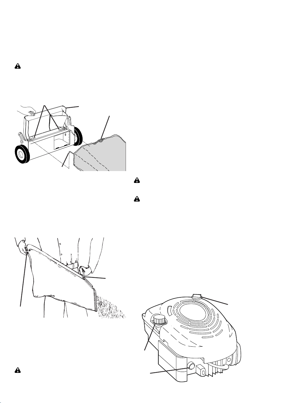
TO EMPTY GRASS CATCHER
1. Lift up on grass catcher using the
frame han dle.
2. Remove grass catcher with clippings
from under lawn mower han dle.
3. Empty clippings from bag using both
frame handle and bag handle.
NOTE: Do not drag the bag when empty-
ing; it will cause unnecessary wear.

8
MAX 1/3
TO START ENGINE
NOTE: Due to protective coatings on the
engine, a small amount of smoke may be
present during the initial use of the prod-
uct and should be considered normal.
1. To start a cold engine, push primer
three (3) times before trying to start.
Use a fi rm push. This step is not
usually necessary when starting an
engine which has already run for a few
minutes.
2. Move throttle control lever to FAST
position.
3. Hold operator presence control bar
down to the han dle and pull starter
handle quickly. Do not allow starter
rope to snap back.
TO STOP ENGINE
• To stop engine, release operator pres-
ence con trol bar.
NOTE: In cooler weather it may be
necessary to repeat priming steps. In
warmer weather over priming may cause
fl ooding and engine will not start. If you
do fl ood engine, wait a few minutes before
attempting to start and do not repeat
priming steps.
MOWING TIPS
• Under certain conditions, such as very
tall grass, it may be nec es sary to raise
the height of cut to reduce pushing
effort and to keep from overloading the
engine and leaving clumps of grass clip-
pings. It may also be necessary to re-
duce ground speed and/or run the lawn
mower over the area a sec ond time.
• For extremely heavy cutting, re duce the
width of cut by over lap ping previously
cut path and mow slowly.
• For better grass bagging and most cut-
ting conditions, the engine speed should
be set in the FAST po si tion.
• When using a rear discharge lawn
mower in moist, heavy grass, clumps
of cut grass may not enter the grass
catcher. Reduce ground speed (pushing
speed) and/or run the lawn mower over
the area a second time.
• If a trail of clippings is left on the right
side of a rear discharge mow er, mow in
a clockwise direction with a small overlap
to collect the clippings on the next pass.
• Pores in cloth grass catchers can be-
come fi lled with dirt and dust with use
and catchers will collect less grass. To
prevent this, reg u lar ly hose catcher off
with water and let dry before using.
• Keep top of engine around starter clear and
clean of grass clippings and chaff. This will
help engine air fl ow and extend engine life.
MULCHING MOWING TIPS
IMPORTANT: For best performance,
keep mower housing free of built-up
grass and trash. See “CLEANING” in the
Maintenance section of this manual.
• The special mulching blade will recut
the grass clip pings many times and
reduce them in size so that as they fall
onto the lawn they will disperse into
the grass and not be noticed. Also, the
mulched grass will bio de grade quickly
to provide nu tri ents for the lawn. Always
mulch with your highest engine (blade)
speed as this will provide the best recut-
ting action of the blades.
• Avoid cutting your lawn when it is wet.
Wet grass tends to form clumps and
in ter feres with the mulch ing action. The
best time to mow your lawn is the early
afternoon. At this time the grass has
dried and the newly cut area will not be
exposed to the direct sun.
• For best results, adjust the lawn mower
cutting height so that the lawn mower
cuts off only the top one-third of the
grass blades. If the lawn is over grown it
will be necessary to raise the height of
cut to reduce pushing effort and to keep
from over load ing the engine and leaving
clumps of mulched grass. For ex tremely
heavy grass, reduce your width of cut
by overlapping previously cut path and
mow slowly.
• Certain types of grass and grass
con di tions may re quire that an area be
mulched a second time to com pletely
hide the clip pings. When doing a sec-
ond cut, mow across or per pen dic u lar to
the fi rst cut path.
• Change your cutting pattern from week
to week. Mow north to south one week
then change to east to west the next
week. This will help prevent matting and
graining of the lawn.
21
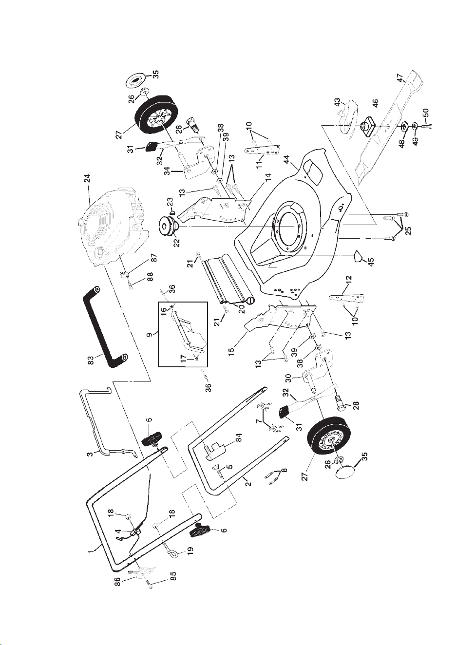
CRAFTSMAN ROTARY LAWN MOWER - - MODEL NUMBER 944.362310
KEY PART
NO. NO. DESCRIPTION
KEY PART
NO. NO. DESCRIPTION
1 184586 Control Cable Assembly
2 167387 Bearing, Wheel Adjuster
3 751152 Locknut #10-24
4 158755 Hex Washer Head Screw 1/4-20 x 2.12
5 175436 V-Belt
6 150495 Spring Retainer
8 180625 Hubcap
9 145212 Locknut
11 180775 Wheel & Tire Assembly
12 12000058 E-Ring
13 137054 Pinion
14 180504 Dust Cover
15 88118 Felt Washer
16 67725 Washer 1/2 x 1-1/2 x .134
18 701037 Selector Knob
26 175262 Pan Head Tapping Screw #10-24 x 2-3/4
28 178843 Drive Cover
31 132010 Hex Flange Nut
32 137052 Drive Pulley
35 151521 Kit, Wheel Adjuster, LH
(Includes Knob and Bearing)
36 175258 Gear Case Assembly
37 137090 Spring
38 63601 Locknut 1/4-20
40 75192 Spring
41 151520 Kit, Wheel Adjuster, RH
(Includes Knob and Bearing)
54 181372 Grassbag Assembly
55 175739 Driveshaft Cover
57 175058 Frame
NOTE: All component dimensions given in U.S. inches.
1 inch = 25.4 mm
20
CRAFTSMAN ROTARY LAWN MOWER - - MODEL NUMBER 944.362310
9
MAINTENANCE
LUBRICATION CHARTGENERAL RECOMMENDATIONS
The warranty on this lawn mower does not
cover items that have been subjected to
operator abuse or negligence. To receive
full value from the warranty, operator
must maintain mower as instructed in this
manual.
Some adjustments will need to be made
periodically to properly maintain your unit.
All adjustments in the Service and Ad just -
ments section of this manual should be
checked at least once each season.
• Once a year, replace the spark plug,
replace air fi lter element and check
blade for wear. A new spark plug and
clean/new air fi lter element assure
proper air-fuel mix ture and help your
engine run better and last longer.
• Follow the maintenance schedule in this
manual.
BEFORE EACH USE
• Check engine oil level.
• Check for loose fasteners.
LUBRICATION
Keep unit well lubricated (See “LU BRI -
CA TION CHART”).
➀
Spray lubricant
➁
See “ENGINE” in Maintenance section.
IMPORTANT: Do not oil or grease
plastic wheel bearings. Viscous lu bri -
cants will attract dust and dirt that will
short en the life of the self-lu bri cat ing
bearings. If you feel they must be
lu bri cated, use only a dry, pow dered
graphite type lubricant spar ingly.
➀
Wheel
adjuster (on
each wheel)
➁
Engine oil
➀
Rear door
hinge
➀
Handle bracket mounting pins

10
PRODUCT SPECIFICATIONS
Serial Number:
Date of Purchase:
Gasoline Capacity / Type: 1,5 Liters (Unleaded Regular)
Oil Type (API-SF-SJ): SAE 30 (above 32°F/0°C); SAE 5W-30 (below 32°F/0°C)
Oil Capacity: 0,58 Liters
Spark Plug: Champion RJ19LM (Gap: 0,76 mm)
Blade Bolt Torque: 35-40 ft. lbs. / 47-54 N-m
• The model and serial numbers will be found on a decal on the rear of the mower
housing. Record both serial number and date of purchase in space provided above.
LAWN MOWER
Always observe safety rules when per-
form ing any main te nance.
TIRES
• Keep tires free of gasoline, oil, or insect
control chemi cals which can harm rubber.
• Avoid stumps, stones, deep ruts, sharp
objects and other hazards that may
cause tire damage.
BLADE CARE
For best results, mower blade must be
kept sharp. Re place bent or dam aged
blades.
TO REMOVE BLADE
1. Disconnect spark plug wire from spark
plug and place wire where it cannot
come in contact with spark plug.
2. Turn lawn mower on its side. Make
sure air fi lter and carburetor are up.
3. Use a wood block between blade and
mower hous ing to prevent blade from
turning when re mov ing blade bolt.
NOTE: Protect your hands with gloves
and/or wrap blade with heavy cloth.
4. Remove blade bolt by turning counter-
clockwise.
5. Remove blade and attaching hard-
ware (bolt, lock wash er and hardened
wash er).
NOTE: Remove the blade adapter and
check the key inside hub of blade adapter.
The key must be in good con di tion to work
properly. Replace adapter if damaged.
TO REPLACE BLADE
1. Position the blade adapter on the en-
gine crank shaft. Be sure key in adapter
and crankshaft keyway are aligned.
2. Position blade on the blade adapter
aligning the two (2) holes in the blade
with the raised lugs on the adapter.
3. Be sure the trailing edge of blade (oppo-
site sharp edge) is up toward the engine.
4. Install the blade bolt with the lock
washer and hardened washer into
blade adapter and crankshaft.
5. Use block of wood between blade and
lawn mower housing and tighten the
blade bolt, turning clockwise.
• The recommended tightening torque is
35-40 ft. lbs. / 47-54 N-m.
IMPORTANT: Blade bolt is grade 8 heat
treated.
TO SHARPEN BLADE
NOTE: We do not recommend sharp en ing
blade - but if you do, be sure the blade is
balanced.
Care should be taken to keep the blade
balanced. An un bal anced blade will
cause eventual damage to lawn mower or
engine.
• The blade can be sharp ened with a fi le
or on a grinding wheel. Do not attempt
to sharpen while on the mower.
• To check blade balance, drive a nail into
a beam or wall. Leave about one inch of
the straight nail ex posed. Place center
hole of blade over the head of the nail.
If blade is balanced, it should remain in
a horizontal position. If either end of the
blade moves downward, sharpen the
heavy end until the blade is balanced.
Blade adapter
Blade
bolt
Crankshaft
keyway
Hardened
washer
Lockwasher
Blade adapter
Key
Blade
Trailing edge
Crank
shaft
19
CRAFTSMAN ROTARY LAWN MOWER - - MODEL NUMBER 944.362310
KEY PART
NO. NO. DESCRIPTION
28 175231 Shoulder Bolt 5/16-18 x .33
30 165761X004 Axle Arm Assembly RR
31 701037 Selector Knob
32 175060X004 Selector Spring
34 165762X004 Axle Arm Assembly LR
35 180625 Hubcap
36 184193 Bolt
38 176185 Washer, Step
39 176235 Pushnut
43 175083 Bottom Belt Cover
44 181991 Lawn Mower Housing (Incl. Key #10, 11, 12& 45)
45 107339X Danger Deal
46 851514 Blade Adapter
47 175064 Blade 21”
48 851074 Hardened Washer
49 850263 Helical Washer 3/8-24 x 1-3/8 Gr. 8
50 851084 Hex Head Machine Screw 3/8-24 x 1-3/8 Gr. 8
83 183684 Grip, Foam
84 165108 Bracket, Anti-Fold
85 144929 Screw
86 700417 Throttle Control
87 111190X Clamp
88 83816 Screw
- - 162300 Warning Decal (Not Shown)
- - 181989 Owner’s Manual, English
- - 181990 Owner’s Manual, French
NOTE: All component dimensions given in U.S. inches.
1 inch = 25.4 mm
1 183485 Upper Handle, with Grip
2 151721X479 Lower Handle
3 180955 Control Bar
4 133107 Engine Zone Control Cable
5 131959 Handle Bolt
6 136376 Handle Knob
7 51793 Hairpin Cotter
8 66426 Wire Tie
9 180479 Rear Door Kit (Incl. Key #16 & 17)
10 128415 Pop Rivet
11 175069X479 Support Bracket LH
12 175070X479 Support Bracket RH
13 17060410 Screw 14-20 x 5/8
14 175082X479 Handle Bracket Assembly (Left)
15 175081X479 Handle Bracket Assembly (Right)
16 180071 Spring LH
17 180072 Spring RH
18 132004 Keps Locknut 1/4-20
19 179585 Rope Guide
20 178398 Rear Skirt
21 88652 Hinge Screw 1/4-20 x 1-1/4
22 84596 Engine Pulley
23 87677 Hi-Pro Key #505
24 - - - Engine, Briggs & Stratton, Model Number
123K02-0183-E1 (See Breakdown)
25 150406 Hex Head Thread Rolling Srew 3/8-16 x 1-1/8
26 83923 Hex Flange Nut
27 150341 Wheel
KEY PART
NO. NO. DESCRIPTION

18
CRAFTSMAN ROTARY LAWN MOWER - - MODEL NUMBER 944.362310
11
GRASS CATCHER
• The grass catcher may be hosed with
water, but must be dry when used.
• Check your grass catcher often for dam-
age or de te ri o ra tion. Through normal use
it will wear. If catcher needs replacing,
replace only with a manufacturer ap proved
replacement catcher. Give the lawn mower
model number when ordering.
DRIVE WHEELS
Check front drive wheels each time be fore
you mow to be sure they move freely.
The wheels not turning freely means
trash, grass cuttings, etc. are in the drive
wheel area and must be cleaned to free
drive wheels.
If necessary to clean the drive wheels, be
sure to clean both front wheels.
1. Remove hubcaps, hairpin cotters and
washers.
2. Remove wheels from wheel ad just ers.
3. Remove any trash or grass cuttings
from inside the dust cover, pinion and/
or drive wheel gear teeth.
4. Put wheels back in place.
NOTE: If after cleaning, the drive wheels
do not turn freely, contact a Sears or other
qualifi ed service center.
GEAR CASE
• To keep your drive system working
properly, the gear case and area around
the drive should be kept clean and free
of trash build-up. Clean under the drive
cover twice a season.
• The gear case is fi lled with lubricant to the
proper level at the factory. The only time
the lubricant needs attention is if service
has been performed on the gear case.
• If lubricant is required, use only Texaco
Starplex Pre mi um 1 Grease, Part No.
750369. Do not substitute.
ENGINE
LUBRICATION
Use only high quality detergent oil rated with
API service classifi cation SF-SJ. Select the
oil's SAE viscosity grade according to your
expected operating temperature.
NOTE: Although multi-viscosity oils
(5W30, 10W30 etc.) improve starting in
cold weather, these multi-viscosity oils will
result in increased oil consumption when
used above 32°F. Check your engine oil
level more frequently to avoid possible
engine damage from running low on oil.
Change the oil after every 25 hours of op-
eration or at least once a year if the lawn
mower is not used for 25 hours in one year.
Check the crankcase oil level before start-
ing the engine and after each five (5)
hours of continuous use. Tighten oil plug
securely each time you check the oil level.
TO CHANGE ENGINE OIL
NOTE: Before tipping lawn mower to drain
oil, drain fuel tank by running engine until
fuel tank is empty.
1. Disconnect spark plug wire from spark
plug and place wire where it cannot
come in contact with spark plug.
2. Remove engine oil cap; lay aside on a
clean surface.
3. Tip lawn mower on its side as shown
and drain oil into a suitable container.
Rock lawn mower back and forth to re-
move any oil trapped inside of engine.
4. Wipe off any spilled oil from lawn
mower or side of engine.
5. Fill engine with oil. The engine oil capacity
is 20 oz. If oil is not com plete ly drained
from engine, you may not need the entire
container of a 20 oz. bottle of oil. Slowly
pour 3/4 of the oil from the container down
the oil fi ll spout into the engine.
6. Wait one minute to allow oil to settle.
Insert and tighten dipstick, then re-
move it to check oil level.
7. Continue adding small amounts of
oil and rechecking the dipstick until it
reads full. DO NOT overfi ll, or engine
will smoke on startup.
8. Always be sure to retighten oil dipstick
before starting engine.
9. Re con nect spark plug wire to spark plug.
TEMPERATURE RANGE ANTICIPATED BEFORE NEXT OIL CHANGE
SAE VISCOSITY GRADES
-20 0 30 40
80
100
-30
-20 0
20 30 40
F
C
32
-10
10
60
5W-30
SAE 30
Container
12
SERVICE AND ADJUSTMENTS
SPARK PLUG
Replace spark plug at the beginning of
each mowing season or after every 100
hours of operation, whichever occurs
fi rst. Spark plug type and gap setting are
shown in “PROD UCT SPEC I FI CA TIONS”
in Maintenance section of this manual.
CLEANING
IMPORTANT: For best performance, keep
mower housing free of built-up grass and
trash. Clean the underside of your mower
after each use.
CAUTION: Disconnect spark plug wire
from spark plug and place wire where it
cannot come in contact with the spark plug.
• Clean the underside of your lawn mower
by scraping to remove build-up of grass
and trash.
• Clean engine often to keep trash from
accumulating. A clogged engine runs
hotter and shortens engine life.
• Keep fi nished surfaces and wheels free
of all gasoline, oil, etc.
• We do not recommend using a garden
hose to clean lawn mower unless the
electrical system, muffl er, air fi lter and
carburetor are covered to keep water
out. Water in engine can result in short-
ened engine life.
CLEAN UNDER DRIVE COVER
Clean under drive cover at least twice a
season. Scrape underside of cover with
putty knife or similar tool to remove any
build-up of trash or grass on underside of
drive cover.
AIR FILTER
Your engine will not run properly and may
be damaged by using a dirty air fi lter.
Replace the air fi lter every 100 hours of
op er a tion or every season, which ev er oc-
curs fi rst. Service air cleaner more often
under dusty conditions.
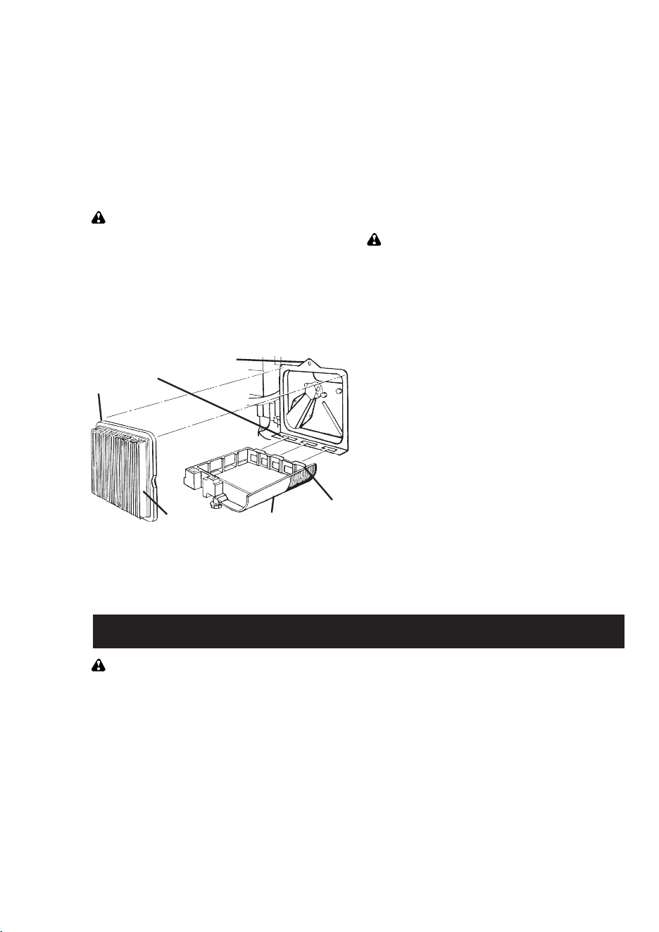
TO CLEAN AIR FILTER
1. Loosen screw and tilt cover to re move.
2. Carefully remove cartridge.
3. Clean by gently tapping on a fl at sur-
face. If very dirty, replace car tridge.
CAUTION: Pe tro leum solvents, such as
ker o sene, are not to be used to clean car-
tridge. They may cause de te ri o ra tion of the
cartridge. Do not oil car tridge. Do not use
pres sur ized air to clean or dry car tridge.
4. Install cartridge, then replace cover
making sure the tabs are aligned with
the slots in the back plate. Fasten
screw securely.
Slots
Lip
Cover
tabs
Back plate
Cartridge Cover
MUFFLER
Inspect and replace corroded muffl er as it
could create a fi re hazard and/or dam age.
WARNING: To avoid serious injury,
before per form ing any service or ad just -
ments:
1. Release control bar and stop engine.
2. Make sure the blade and all moving
parts have completely stopped.
3. Disconnect spark plug wire from spark
plug and place where it cannot come in
contact with plug.
LAWN MOWER
TO ADJUST CUTTING HEIGHT
See “TO ADJUST CUTTING HEIGHT” in
the Operation sec tion of this manual.
REAR DEFLECTOR
The rear defl ector, attached between the
rear wheels of your mower, is provided to
minimize the possibility that objects will
be thrown out of the rear of the mower
into the operator mowing position. If the
defl ector becomes dam aged, it should be
replaced.
17
CRAFTSMAN ROTARY LAWN MOWER - - MODEL NUMBER 944.362310
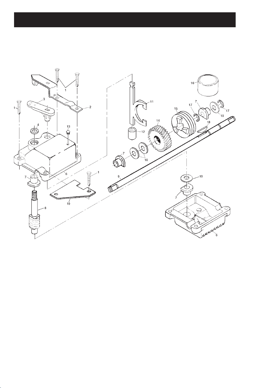
GEAR CASE ASSEMBLY - - PART NUMBER 175258
REPAIR PARTS
KEY PART
NO. NO. DESCRIPTION
1 17490416 Tapping Screw 1/4-20 x 1-1/4
2 175248X004 Engagement Bracket
3 137053 Shifter
4 57072 Seal
6 48373 Gear Case Halves Kit
(Includes Key Numbers 4 and 7)
7 77881 Bearing
8 137051 Worm Shaft
9 175257 Drive Shaft
10 57079 Hardened Washer
11 131484 Clutch Yoke
12 700343 Bushing
13 86447 Plug
14 137050 Helical Gear
15 750436X Clutch Jaw
16 750369 Grease
17 12000003 E-Ring
18 850848 Hi-Pro Key
19 81585X004 Spring Bracket
- - 176293 Kit, Gearcase (Includes Instructions)
NOTE: All component dimensions given in U.S. inches.
1 inch = 25.4 mm
16
Poor cut – 1. Worn, bent or loose blade. 1. Replace blade. Tighten
uneven blade bolt.
2. Wheel heights uneven. 2. Set all wheels at same
height.
3. Buildup of grass, leaves 3. Clean underside of
and trash under mower. mower housing.
Excessive 1. Worn, bent or loose blade. 1. Replace blade. Tighten
vibration blade bolt.
2. Bent engine crankshaft. 2. Contact a Sears or other
qualifi ed service center.
Starter rope 1. Engine fl ywheel brake is on 1. Depress control bar to
hard to pull when control bar is released. upper handle before
pulling starter rope.
2. Bent engine crankshaft. 2. Contact a Sears or other
qualifi ed service center.
3. Blade adapter broken. 3. Replace blade adapter.
4. Blade dragging in grass. 4. Move lawn mower to cut
grass or to hard surface.
Grass catcher 1. Cutting height too low. 1. Raise cutting height.
not fi lling 2. Lift on blade worn off. 2. Replace blade.
(If so equipped) 3. Catcher not venting air. 3. Clean grass catcher.
Hard to push 1. Grass is too high or wheel 1. Raise cutting height.
height is too low.
2. Rear of lawn mower 2. Raise rear of lawn mower
housing or cutting blade housing one (1) setting
dragging in grass. higher.
3. Grass catcher too full. 3. Empty grass catcher.
4. Handle height position not 4. Adjust handle height to suit.
right for you.
Loss of drive 1. Belt wear. 1. Check/replace drive belt.
or slowing of 2. Belt off of pulley. 2. Check/reinstall drive belt.
drive speed 3. Drive cable worn or broken. 3. Replace drive cable.
4. Dirt in drive pinions. 4. Clean drive pinions.
PROBLEM CAUSE CORRECTION
TROUBLESHOOTING - See appropriate section in manual unless directed
to a Sears Service Center.
13
TO REMOVE DRIVE BELT
1. Remove drive cover. Remove belt from
gearcase pulley by push ing down on
pulley and rolling belt off it.
2. Turn lawn mower on its side with air
fi lter and car bu re tor up.
3. Remove blade.
4. Remove debris shield.
5. Remove belt from engine pulley on
crankshaft.
TO REPLACE DRIVE BELT
1. Install new belt on engine pulley.
2. Reinstall debris shield and blade.
3. Return mower to upright po si tion.
4. Install new belt on gearcase pulley.
5. Reinstall drive cover.
NOTE: Always use factory approved belt
to assure fi t and long life.
ENGINE
ENGINE SPEED
Your engine speed has been factory set.
Do not attempt to increase engine speed
or it may result in personal injury. If you
believe that the engine is running too fast
or too slow, take your lawn mower to a
Sears or other qualifi ed service center for
repair and adjustment.
CARBURETOR
Your carburetor is not adjustable. If your
engine does not operate properly due to
suspected carburetor problems, take your
lawn mower to a Sears or other qualifi ed
service center for repair or ad just ment.
IMPORTANT: Never tamper with the
engine governor, which is factory set
for proper engine speed. Over speed ing
the engine above the factory high speed
setting can be dangerous. If you think
the engine-governed high speed needs
adjusting, contact a Sears or other
qualifi ed service center, which has proper
equip ment and ex pe ri ence to make any
nec es sary adjustments.
Mowing
position
Mowing
position
HIGH POSITIONLOW POSITION
Handle
bracket
Hairpin
cotter
Mounting
pin
Belt
Drive
cover
PUSH DOWN
TO ADJUST HANDLE
The handle can be mounted in a high or
low position. The mounting holes in the
bottom of lower handle are off center for
raising or lowering the handle.
NOTE: The upper handle has an “anti-
fold” bracket located on the left side of the
handle. This bracket prevents the upper
handle from folding forward, which helps
protect control cable(s) from damage.
1. Remove upper handle and all parts
attached to lower handle.
2. Remove hairpin cotters from lower
handle bracket mount ing pin.
3. Squeeze lower handle in to remove it
from mounting pins.
4. Turn lower handle over to raise or
lower handle.
5. Squeeze lower handle in and position
holes onto mount ing pins on handle
bracket.
6. Reassemble upper handle and all
parts removed from lower handle.
Lower
handle
ROTATE
Anti-fold
bracket
14
STORAGE
Immediately prepare your lawn mower for
storage at the end of the season or if the
unit will not be used for 30 days or more.
LAWN MOWER
When lawn mower is to be stored for a
period of time, clean it thor oughly, remove
all dirt, grease, leaves, etc. Store in a
clean, dry area.
1. Clean entire lawn mower (See
“CLEANING” in the Maintenance sec-
tion of this manual).
2. Lubricate as shown in the Main te nance
section of this manual.
3. Be sure that all nuts, bolts, screws, and
pins are securely fas tened. Inspect
moving parts for damage, breakage
and wear. Replace if necessary.
4. Touch up all rusted or chipped paint
surfaces; sand lightly before painting.
HANDLE
You can fold your lawn mower handle for
storage.
NOTE: The upper handle has an “anti-
fold” bracket located on the left side of the
handle. This bracket prevents the upper
handle from folding forward, which helps
protect control cable(s) from damage.
1. Squeeze the bottom ends of the lower
handle toward each other until the
lower handle clears the handle bracket,
then move handle forward.
2. Loosen upper handle mounting bolts
enough to allow upper handle to be
folded back.
IMPORTANT: When folding the handle for
storage or transportation, be sure to fold
the handle as shown or you may damage
the control cables.
• When setting up your handle from the
storage position, the lower han dle will
automatically lock into the mow ing posi-
tion.
Lower handle
SQUEEZE
TO FOLD
ENGINE
FUEL SYS TEM
IMPORTANT: It is important to prevent
gum deposits from forming in essential
fuel system parts such as carburetor, fuel
fi lter, fuel hose or tank during storage.
Also, alcohol blended fuels (called gasohol
or using ethanol or methanol) can attract
moisture which leads to separation and
formation of acids during storage. Acidic
gas can damage the fuel system of an
engine while in storage.
1. Drain the fuel tank.
2. Start the engine and let it run until the
fuel lines and carburetor are empty.
• Never use engine or carburetor cleaner
prod ucts in the fuel tank or per ma nent
damage may occur.
• Use fresh fuel next season.
NOTE: Fuel stabilizer is an acceptable
al ter na tive in minimizing the formation
of fuel gum deposits during stor age.
Add stabilizer to gasoline in fuel tank or
storage con tain er. Always follow the mix
ratio found on stabilizer container. Run
engine at least 10 min utes after adding
stabilizer to allow the stabilizer to reach
the car bu re tor. Do not drain the gas tank
and carburetor if using fuel stabilizer.
ENGINE OIL
Drain oil (with engine warm) and replace
with clean engine oil. (See “ENGINE” in
the Maintenance section of this manual).
Mowing position
FOLD
BACKWARD
Operator presence
control bar
FOLD
FORWARD
FOR
STORAGE
Upper handle
Lower
handle
Anti-
fold
bracket
15
CYLINDER
1. Remove spark plug.
2. Pour 30 ml of oil through spark plug
hole into cylinder.
3. Pull starter handle slowly a few times to
dis trib ute oil.
4. Replace with new spark plug.
OTHER
• Do not store gasoline from one season
to another.
• Replace your gasoline can if your can
starts to rust. Rust and/or dirt in your
gasoline will cause problems.
• If possible, store your unit indoors and
cover it to protect it from dust and dirt.
• Cover your unit with a suitable pro tec tive
cover that does not retain moisture. Do
not use plastic. Plastic cannot breathe,
which allows con den sa tion to form and
will cause your unit to rust.
IMPORTANT: Never cover mower while
en gine and exhaust areas are still warm.
CAUTION: Never store the lawn mower
with gaso line in the tank inside a build ing
where fumes may reach an open fl ame
or spark. Allow the engine to cool before
storing in any en clo sure.
Does not start 1. Dirty air fi lter. 1. Clean/replace air fi lter.
2. Out of fuel. 2. Fill fuel tank.
3. Stale fuel. 3. Drain tank and refi ll with
fresh, clean fuel.
4. Water in fuel. 4. Drain fuel tank and
carburetor and refi ll tank
with fresh gasoline.
5. Spark plug wire is 5. Connect wire to plug.
disconnected.
6. Bad spark plug. 6. Replace spark plug.
7. Loose blade or broken 7. Tighten blade bolt or
blade adapter. replace blade adapter.
8. Control bar in released 8. Depress control bar to
position. handle.
9. Control bar defective. 9. Replace control bar.
10.Fuel valve lever (if so 10.Turn fuel valve lever
equipped) in OFF position. to the ON position.
11.Weak battery (if equipped). 11.Charge battery.
12.Disconnected battery 12.Connect battery to engine.
connector (if equipped).
Loss of power 1. Rear of lawn mower 1. Set to “Higher Cut”
housing or cutting blade position.
dragging in heavy grass.
2. Cutting too much grass. 2. Set to “Higher Cut”
position.
3. Dirty air fi lter. 3. Clean/replace air fi lter.
4. Buildup of grass, leaves, 4. Clean underside of mower
and trash under mower. housing.
5. Too much oil in engine. 5. Check oil level.
6. Walking speed too fast. 6. Cut at slower walking speed.
PROBLEM CAUSE CORRECTION
TROUBLESHOOTING - See appropriate section in manual unless directed
to a Sears Service Center.

16
Poor cut – 1. Worn, bent or loose blade. 1. Replace blade. Tighten
uneven blade bolt.
2. Wheel heights uneven. 2. Set all wheels at same
height.
3. Buildup of grass, leaves 3. Clean underside of
and trash under mower. mower housing.
Excessive 1. Worn, bent or loose blade. 1. Replace blade. Tighten
vibration blade bolt.
2. Bent engine crankshaft. 2. Contact a Sears or other
qualifi ed service center.
Starter rope 1. Engine fl ywheel brake is on 1. Depress control bar to
hard to pull when control bar is released. upper handle before
pulling starter rope.
2. Bent engine crankshaft. 2. Contact a Sears or other
qualifi ed service center.
3. Blade adapter broken. 3. Replace blade adapter.
4. Blade dragging in grass. 4. Move lawn mower to cut
grass or to hard surface.
Grass catcher 1. Cutting height too low. 1. Raise cutting height.
not fi lling 2. Lift on blade worn off. 2. Replace blade.
(If so equipped) 3. Catcher not venting air. 3. Clean grass catcher.
Hard to push 1. Grass is too high or wheel 1. Raise cutting height.
height is too low.
2. Rear of lawn mower 2. Raise rear of lawn mower
housing or cutting blade housing one (1) setting
dragging in grass. higher.
3. Grass catcher too full. 3. Empty grass catcher.
4. Handle height position not 4. Adjust handle height to suit.
right for you.
Loss of drive 1. Belt wear. 1. Check/replace drive belt.
or slowing of 2. Belt off of pulley. 2. Check/reinstall drive belt.
drive speed 3. Drive cable worn or broken. 3. Replace drive cable.
4. Dirt in drive pinions. 4. Clean drive pinions.
PROBLEM CAUSE CORRECTION
TROUBLESHOOTING - See appropriate section in manual unless directed
to a Sears Service Center.
13
TO REMOVE DRIVE BELT
1. Remove drive cover. Remove belt from
gearcase pulley by push ing down on
pulley and rolling belt off it.
2. Turn lawn mower on its side with air
fi lter and car bu re tor up.
3. Remove blade.
4. Remove debris shield.
5. Remove belt from engine pulley on
crankshaft.
TO REPLACE DRIVE BELT
1. Install new belt on engine pulley.
2. Reinstall debris shield and blade.
3. Return mower to upright po si tion.
4. Install new belt on gearcase pulley.
5. Reinstall drive cover.
NOTE: Always use factory approved belt
to assure fi t and long life.
ENGINE
ENGINE SPEED
Your engine speed has been factory set.
Do not attempt to increase engine speed
or it may result in personal injury. If you
believe that the engine is running too fast
or too slow, take your lawn mower to a
Sears or other qualifi ed service center for
repair and adjustment.
CARBURETOR
Your carburetor is not adjustable. If your
engine does not operate properly due to
suspected carburetor problems, take your
lawn mower to a Sears or other qualifi ed
service center for repair or ad just ment.
IMPORTANT: Never tamper with the
engine governor, which is factory set
for proper engine speed. Over speed ing
the engine above the factory high speed
setting can be dangerous. If you think
the engine-governed high speed needs
adjusting, contact a Sears or other
qualifi ed service center, which has proper
equip ment and ex pe ri ence to make any
nec es sary adjustments.
Mowing
position
Mowing
position
HIGH POSITIONLOW POSITION
Handle
bracket
Hairpin
cotter
Mounting
pin
Belt
Drive
cover
PUSH DOWN
TO ADJUST HANDLE
The handle can be mounted in a high or
low position. The mounting holes in the
bottom of lower handle are off center for
raising or lowering the handle.
NOTE: The upper handle has an “anti-
fold” bracket located on the left side of the
handle. This bracket prevents the upper
handle from folding forward, which helps
protect control cable(s) from damage.
1. Remove upper handle and all parts
attached to lower handle.
2. Remove hairpin cotters from lower
handle bracket mount ing pin.
3. Squeeze lower handle in to remove it
from mounting pins.
4. Turn lower handle over to raise or
lower handle.
5. Squeeze lower handle in and position
holes onto mount ing pins on handle
bracket.
6. Reassemble upper handle and all
parts removed from lower handle.
Lower
handle
ROTATE
Anti-fold
bracket
12
SERVICE AND ADJUSTMENTS
SPARK PLUG
Replace spark plug at the beginning of
each mowing season or after every 100
hours of operation, whichever occurs
fi rst. Spark plug type and gap setting are
shown in “PROD UCT SPEC I FI CA TIONS”
in Maintenance section of this manual.
CLEANING
IMPORTANT: For best performance, keep
mower housing free of built-up grass and
trash. Clean the underside of your mower
after each use.
CAUTION: Disconnect spark plug wire
from spark plug and place wire where it
cannot come in contact with the spark plug.
• Clean the underside of your lawn mower
by scraping to remove build-up of grass
and trash.
• Clean engine often to keep trash from
accumulating. A clogged engine runs
hotter and shortens engine life.
• Keep fi nished surfaces and wheels free
of all gasoline, oil, etc.
• We do not recommend using a garden
hose to clean lawn mower unless the
electrical system, muffl er, air fi lter and
carburetor are covered to keep water
out. Water in engine can result in short-
ened engine life.
CLEAN UNDER DRIVE COVER
Clean under drive cover at least twice a
season. Scrape underside of cover with
putty knife or similar tool to remove any
build-up of trash or grass on underside of
drive cover.
AIR FILTER
Your engine will not run properly and may
be damaged by using a dirty air fi lter.
Replace the air fi lter every 100 hours of
op er a tion or every season, which ev er oc-
curs fi rst. Service air cleaner more often
under dusty conditions.
TO CLEAN AIR FILTER
1. Loosen screw and tilt cover to re move.
2. Carefully remove cartridge.
3. Clean by gently tapping on a fl at sur-
face. If very dirty, replace car tridge.
CAUTION: Pe tro leum solvents, such as
ker o sene, are not to be used to clean car-
tridge. They may cause de te ri o ra tion of the
cartridge. Do not oil car tridge. Do not use
pres sur ized air to clean or dry car tridge.
4. Install cartridge, then replace cover
making sure the tabs are aligned with
the slots in the back plate. Fasten
screw securely.
Slots
Lip
Cover
tabs
Back plate
Cartridge Cover
MUFFLER
Inspect and replace corroded muffl er as it
could create a fi re hazard and/or dam age.
WARNING: To avoid serious injury,
before per form ing any service or ad just -
ments:
1. Release control bar and stop engine.
2. Make sure the blade and all moving
parts have completely stopped.
3. Disconnect spark plug wire from spark
plug and place where it cannot come in
contact with plug.
LAWN MOWER
TO ADJUST CUTTING HEIGHT
See “TO ADJUST CUTTING HEIGHT” in
the Operation sec tion of this manual.
REAR DEFLECTOR
The rear defl ector, attached between the
rear wheels of your mower, is provided to
minimize the possibility that objects will
be thrown out of the rear of the mower
into the operator mowing position. If the
defl ector becomes dam aged, it should be
replaced.
17
CRAFTSMAN ROTARY LAWN MOWER - - MODEL NUMBER 944.362310
GEAR CASE ASSEMBLY - - PART NUMBER 175258
REPAIR PARTS
KEY PART
NO. NO. DESCRIPTION
1 17490416 Tapping Screw 1/4-20 x 1-1/4
2 175248X004 Engagement Bracket
3 137053 Shifter
4 57072 Seal
6 48373 Gear Case Halves Kit
(Includes Key Numbers 4 and 7)
7 77881 Bearing
8 137051 Worm Shaft
9 175257 Drive Shaft
10 57079 Hardened Washer
11 131484 Clutch Yoke
12 700343 Bushing
13 86447 Plug
14 137050 Helical Gear
15 750436X Clutch Jaw
16 750369 Grease
17 12000003 E-Ring
18 850848 Hi-Pro Key
19 81585X004 Spring Bracket
- - 176293 Kit, Gearcase (Includes Instructions)
NOTE: All component dimensions given in U.S. inches.
1 inch = 25.4 mm
18
CRAFTSMAN ROTARY LAWN MOWER - - MODEL NUMBER 944.362310
11
GRASS CATCHER
• The grass catcher may be hosed with
water, but must be dry when used.
• Check your grass catcher often for dam-
age or de te ri o ra tion. Through normal use
it will wear. If catcher needs replacing,
replace only with a manufacturer ap proved
replacement catcher. Give the lawn mower
model number when ordering.
DRIVE WHEELS
Check front drive wheels each time be fore
you mow to be sure they move freely.
The wheels not turning freely means
trash, grass cuttings, etc. are in the drive
wheel area and must be cleaned to free
drive wheels.
If necessary to clean the drive wheels, be
sure to clean both front wheels.
1. Remove hubcaps, hairpin cotters and
washers.
2. Remove wheels from wheel ad just ers.
3. Remove any trash or grass cuttings
from inside the dust cover, pinion and/
or drive wheel gear teeth.
4. Put wheels back in place.
NOTE: If after cleaning, the drive wheels
do not turn freely, contact a Sears or other
qualifi ed service center.
GEAR CASE
• To keep your drive system working
properly, the gear case and area around
the drive should be kept clean and free
of trash build-up. Clean under the drive
cover twice a season.
• The gear case is fi lled with lubricant to the
proper level at the factory. The only time
the lubricant needs attention is if service
has been performed on the gear case.
• If lubricant is required, use only Texaco
Starplex Pre mi um 1 Grease, Part No.
750369. Do not substitute.
ENGINE
LUBRICATION
Use only high quality detergent oil rated with
API service classifi cation SF-SJ. Select the
oil's SAE viscosity grade according to your
expected operating temperature.
NOTE: Although multi-viscosity oils
(5W30, 10W30 etc.) improve starting in
cold weather, these multi-viscosity oils will
result in increased oil consumption when
used above 32°F. Check your engine oil
level more frequently to avoid possible
engine damage from running low on oil.
Change the oil after every 25 hours of op-
eration or at least once a year if the lawn
mower is not used for 25 hours in one year.
Check the crankcase oil level before start-
ing the engine and after each five (5)
hours of continuous use. Tighten oil plug
securely each time you check the oil level.
TO CHANGE ENGINE OIL
NOTE: Before tipping lawn mower to drain
oil, drain fuel tank by running engine until
fuel tank is empty.
1. Disconnect spark plug wire from spark
plug and place wire where it cannot
come in contact with spark plug.
2. Remove engine oil cap; lay aside on a
clean surface.
3. Tip lawn mower on its side as shown
and drain oil into a suitable container.
Rock lawn mower back and forth to re-
move any oil trapped inside of engine.
4. Wipe off any spilled oil from lawn
mower or side of engine.
5. Fill engine with oil. The engine oil capacity
is 20 oz. If oil is not com plete ly drained
from engine, you may not need the entire
container of a 20 oz. bottle of oil. Slowly
pour 3/4 of the oil from the container down
the oil fi ll spout into the engine.
6. Wait one minute to allow oil to settle.
Insert and tighten dipstick, then re-
move it to check oil level.
7. Continue adding small amounts of
oil and rechecking the dipstick until it
reads full. DO NOT overfi ll, or engine
will smoke on startup.
8. Always be sure to retighten oil dipstick
before starting engine.
9. Re con nect spark plug wire to spark plug.
TEMPERATURE RANGE ANTICIPATED BEFORE NEXT OIL CHANGE
SAE VISCOSITY GRADES
-20 0 30 40
80
100
-30
-20 0
20 30 40
F
C
32
-10
10
60
5W-30
SAE 30
Container

10
PRODUCT SPECIFICATIONS
Serial Number:
Date of Purchase:
Gasoline Capacity / Type: 1,5 Liters (Unleaded Regular)
Oil Type (API-SF-SJ): SAE 30 (above 32°F/0°C); SAE 5W-30 (below 32°F/0°C)
Oil Capacity: 0,58 Liters
Spark Plug: Champion RJ19LM (Gap: 0,76 mm)
Blade Bolt Torque: 35-40 ft. lbs. / 47-54 N-m
• The model and serial numbers will be found on a decal on the rear of the mower
housing. Record both serial number and date of purchase in space provided above.
LAWN MOWER
Always observe safety rules when per-
form ing any main te nance.
TIRES
• Keep tires free of gasoline, oil, or insect
control chemi cals which can harm rubber.
• Avoid stumps, stones, deep ruts, sharp
objects and other hazards that may
cause tire damage.
BLADE CARE
For best results, mower blade must be
kept sharp. Re place bent or dam aged
blades.
TO REMOVE BLADE
1. Disconnect spark plug wire from spark
plug and place wire where it cannot
come in contact with spark plug.
2. Turn lawn mower on its side. Make
sure air fi lter and carburetor are up.
3. Use a wood block between blade and
mower hous ing to prevent blade from
turning when re mov ing blade bolt.
NOTE: Protect your hands with gloves
and/or wrap blade with heavy cloth.
4. Remove blade bolt by turning counter-
clockwise.
5. Remove blade and attaching hard-
ware (bolt, lock wash er and hardened
wash er).
NOTE: Remove the blade adapter and
check the key inside hub of blade adapter.
The key must be in good con di tion to work
properly. Replace adapter if damaged.
TO REPLACE BLADE
1. Position the blade adapter on the en-
gine crank shaft. Be sure key in adapter
and crankshaft keyway are aligned.
2. Position blade on the blade adapter
aligning the two (2) holes in the blade
with the raised lugs on the adapter.
3. Be sure the trailing edge of blade (oppo-
site sharp edge) is up toward the engine.
4. Install the blade bolt with the lock
washer and hardened washer into
blade adapter and crankshaft.
5. Use block of wood between blade and
lawn mower housing and tighten the
blade bolt, turning clockwise.
• The recommended tightening torque is
35-40 ft. lbs. / 47-54 N-m.
IMPORTANT: Blade bolt is grade 8 heat
treated.
TO SHARPEN BLADE
NOTE: We do not recommend sharp en ing
blade - but if you do, be sure the blade is
balanced.
Care should be taken to keep the blade
balanced. An un bal anced blade will
cause eventual damage to lawn mower or
engine.
• The blade can be sharp ened with a fi le
or on a grinding wheel. Do not attempt
to sharpen while on the mower.
• To check blade balance, drive a nail into
a beam or wall. Leave about one inch of
the straight nail ex posed. Place center
hole of blade over the head of the nail.
If blade is balanced, it should remain in
a horizontal position. If either end of the
blade moves downward, sharpen the
heavy end until the blade is balanced.
Blade adapter
Blade
bolt
Crankshaft
keyway
Hardened
washer
Lockwasher
Blade adapter
Key
Blade
Trailing edge
Crank
shaft
19
CRAFTSMAN ROTARY LAWN MOWER - - MODEL NUMBER 944.362310
KEY PART
NO. NO. DESCRIPTION
28 175231 Shoulder Bolt 5/16-18 x .33
30 165761X004 Axle Arm Assembly RR
31 701037 Selector Knob
32 175060X004 Selector Spring
34 165762X004 Axle Arm Assembly LR
35 180625 Hubcap
36 184193 Bolt
38 176185 Washer, Step
39 176235 Pushnut
43 175083 Bottom Belt Cover
44 181991 Lawn Mower Housing (Incl. Key #10, 11, 12& 45)
45 107339X Danger Deal
46 851514 Blade Adapter
47 175064 Blade 21”
48 851074 Hardened Washer
49 850263 Helical Washer 3/8-24 x 1-3/8 Gr. 8
50 851084 Hex Head Machine Screw 3/8-24 x 1-3/8 Gr. 8
83 183684 Grip, Foam
84 165108 Bracket, Anti-Fold
85 144929 Screw
86 700417 Throttle Control
87 111190X Clamp
88 83816 Screw
- - 162300 Warning Decal (Not Shown)
- - 181989 Owner’s Manual, English
- - 181990 Owner’s Manual, French
NOTE: All component dimensions given in U.S. inches.
1 inch = 25.4 mm
1 183485 Upper Handle, with Grip
2 151721X479 Lower Handle
3 180955 Control Bar
4 133107 Engine Zone Control Cable
5 131959 Handle Bolt
6 136376 Handle Knob
7 51793 Hairpin Cotter
8 66426 Wire Tie
9 180479 Rear Door Kit (Incl. Key #16 & 17)
10 128415 Pop Rivet
11 175069X479 Support Bracket LH
12 175070X479 Support Bracket RH
13 17060410 Screw 14-20 x 5/8
14 175082X479 Handle Bracket Assembly (Left)
15 175081X479 Handle Bracket Assembly (Right)
16 180071 Spring LH
17 180072 Spring RH
18 132004 Keps Locknut 1/4-20
19 179585 Rope Guide
20 178398 Rear Skirt
21 88652 Hinge Screw 1/4-20 x 1-1/4
22 84596 Engine Pulley
23 87677 Hi-Pro Key #505
24 - - - Engine, Briggs & Stratton, Model Number
123K02-0183-E1 (See Breakdown)
25 150406 Hex Head Thread Rolling Srew 3/8-16 x 1-1/8
26 83923 Hex Flange Nut
27 150341 Wheel
KEY PART
NO. NO. DESCRIPTION
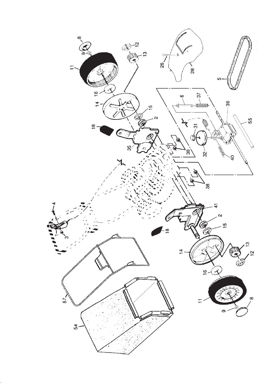
20
CRAFTSMAN ROTARY LAWN MOWER - - MODEL NUMBER 944.362310
9
MAINTENANCE
LUBRICATION CHARTGENERAL RECOMMENDATIONS
The warranty on this lawn mower does not
cover items that have been subjected to
operator abuse or negligence. To receive
full value from the warranty, operator
must maintain mower as instructed in this
manual.
Some adjustments will need to be made
periodically to properly maintain your unit.
All adjustments in the Service and Ad just -
ments section of this manual should be
checked at least once each season.
• Once a year, replace the spark plug,
replace air fi lter element and check
blade for wear. A new spark plug and
clean/new air fi lter element assure
proper air-fuel mix ture and help your
engine run better and last longer.
• Follow the maintenance schedule in this
manual.
BEFORE EACH USE
• Check engine oil level.
• Check for loose fasteners.
LUBRICATION
Keep unit well lubricated (See “LU BRI -
CA TION CHART”).
➀
Spray lubricant
➁
See “ENGINE” in Maintenance section.
IMPORTANT: Do not oil or grease
plastic wheel bearings. Viscous lu bri -
cants will attract dust and dirt that will
short en the life of the self-lu bri cat ing
bearings. If you feel they must be
lu bri cated, use only a dry, pow dered
graphite type lubricant spar ingly.
➀
Wheel
adjuster (on
each wheel)
➁
Engine oil
➀
Rear door
hinge
➀
Handle bracket mounting pins

8
MAX 1/3
TO START ENGINE
NOTE: Due to protective coatings on the
engine, a small amount of smoke may be
present during the initial use of the prod-
uct and should be considered normal.
1. To start a cold engine, push primer
three (3) times before trying to start.
Use a fi rm push. This step is not
usually necessary when starting an
engine which has already run for a few
minutes.
2. Move throttle control lever to FAST
position.
3. Hold operator presence control bar
down to the han dle and pull starter
handle quickly. Do not allow starter
rope to snap back.
TO STOP ENGINE
• To stop engine, release operator pres-
ence con trol bar.
NOTE: In cooler weather it may be
necessary to repeat priming steps. In
warmer weather over priming may cause
fl ooding and engine will not start. If you
do fl ood engine, wait a few minutes before
attempting to start and do not repeat
priming steps.
MOWING TIPS
• Under certain conditions, such as very
tall grass, it may be nec es sary to raise
the height of cut to reduce pushing
effort and to keep from overloading the
engine and leaving clumps of grass clip-
pings. It may also be necessary to re-
duce ground speed and/or run the lawn
mower over the area a sec ond time.
• For extremely heavy cutting, re duce the
width of cut by over lap ping previously
cut path and mow slowly.
• For better grass bagging and most cut-
ting conditions, the engine speed should
be set in the FAST po si tion.
• When using a rear discharge lawn
mower in moist, heavy grass, clumps
of cut grass may not enter the grass
catcher. Reduce ground speed (pushing
speed) and/or run the lawn mower over
the area a second time.
• If a trail of clippings is left on the right
side of a rear discharge mow er, mow in
a clockwise direction with a small overlap
to collect the clippings on the next pass.
• Pores in cloth grass catchers can be-
come fi lled with dirt and dust with use
and catchers will collect less grass. To
prevent this, reg u lar ly hose catcher off
with water and let dry before using.
• Keep top of engine around starter clear and
clean of grass clippings and chaff. This will
help engine air fl ow and extend engine life.
MULCHING MOWING TIPS
IMPORTANT: For best performance,
keep mower housing free of built-up
grass and trash. See “CLEANING” in the
Maintenance section of this manual.
• The special mulching blade will recut
the grass clip pings many times and
reduce them in size so that as they fall
onto the lawn they will disperse into
the grass and not be noticed. Also, the
mulched grass will bio de grade quickly
to provide nu tri ents for the lawn. Always
mulch with your highest engine (blade)
speed as this will provide the best recut-
ting action of the blades.
• Avoid cutting your lawn when it is wet.
Wet grass tends to form clumps and
in ter feres with the mulch ing action. The
best time to mow your lawn is the early
afternoon. At this time the grass has
dried and the newly cut area will not be
exposed to the direct sun.
• For best results, adjust the lawn mower
cutting height so that the lawn mower
cuts off only the top one-third of the
grass blades. If the lawn is over grown it
will be necessary to raise the height of
cut to reduce pushing effort and to keep
from over load ing the engine and leaving
clumps of mulched grass. For ex tremely
heavy grass, reduce your width of cut
by overlapping previously cut path and
mow slowly.
• Certain types of grass and grass
con di tions may re quire that an area be
mulched a second time to com pletely
hide the clip pings. When doing a sec-
ond cut, mow across or per pen dic u lar to
the fi rst cut path.
• Change your cutting pattern from week
to week. Mow north to south one week
then change to east to west the next
week. This will help prevent matting and
graining of the lawn.
21
CRAFTSMAN ROTARY LAWN MOWER - - MODEL NUMBER 944.362310
KEY PART
NO. NO. DESCRIPTION
KEY PART
NO. NO. DESCRIPTION
1 184586 Control Cable Assembly
2 167387 Bearing, Wheel Adjuster
3 751152 Locknut #10-24
4 158755 Hex Washer Head Screw 1/4-20 x 2.12
5 175436 V-Belt
6 150495 Spring Retainer
8 180625 Hubcap
9 145212 Locknut
11 180775 Wheel & Tire Assembly
12 12000058 E-Ring
13 137054 Pinion
14 180504 Dust Cover
15 88118 Felt Washer
16 67725 Washer 1/2 x 1-1/2 x .134
18 701037 Selector Knob
26 175262 Pan Head Tapping Screw #10-24 x 2-3/4
28 178843 Drive Cover
31 132010 Hex Flange Nut
32 137052 Drive Pulley
35 151521 Kit, Wheel Adjuster, LH
(Includes Knob and Bearing)
36 175258 Gear Case Assembly
37 137090 Spring
38 63601 Locknut 1/4-20
40 75192 Spring
41 151520 Kit, Wheel Adjuster, RH
(Includes Knob and Bearing)
54 181372 Grassbag Assembly
55 175739 Driveshaft Cover
57 175058 Frame
NOTE: All component dimensions given in U.S. inches.
1 inch = 25.4 mm
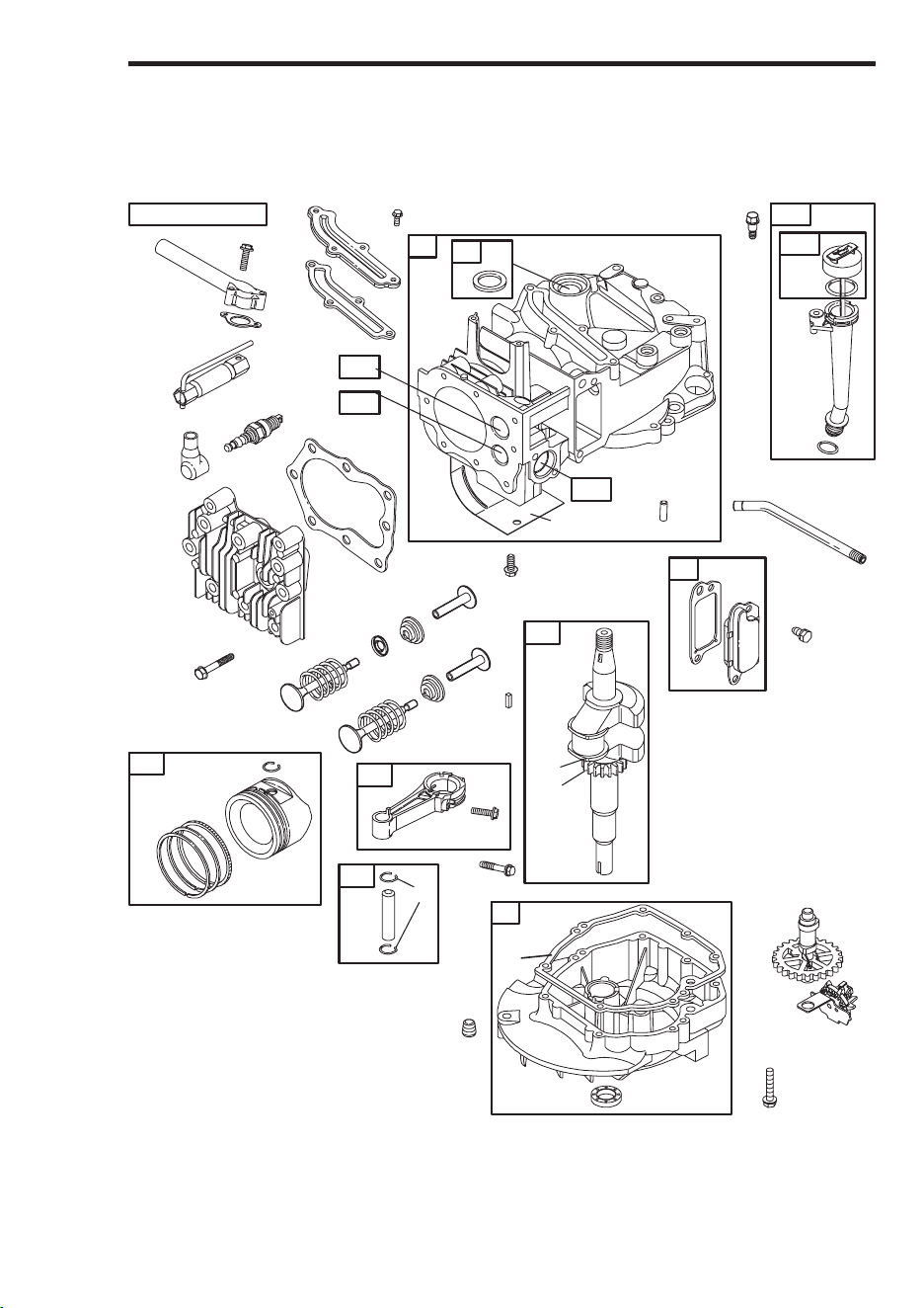
22
MODEL NUMBER 123K02-0183-E1
BRIGGS & STRATTON 4-CYCLE ENGINE
307
13
337
635
383
3
306
11
9
10
54
50
51
7
5
584
585
684
287
525
524
842
1019 LABEL KIT
1
8
847
523
27
27
32
26
28
25
29
40
40
35
36
33
45
34
45
24
741
16
146
20
12
22
46
43
15
4
32A
718
868
2
871
870
869
7
Grass
catcher
frame
handle
Bag
handle
BEFORE STARTING ENGINE
ADD OIL
Your lawnmower is shipped without oil in
the engine. For type and grade of oil to
use, see “EN GINE” in the Maintenance
section of this manual.
CAUTION: DO NOT overfi ll engine with
oil, or it will smoke on startup.
1. Be sure lawnmower is level and area
around oil fi ll is clean.
2. Remove oil dipstick from oil fi ll spout.
Make sure that rim of spout is clean.
3. You receive a container of oil with the
unit. Slowly pour the entire container
down the oil fi ll spout into the engine.
4. Wait one minute to allow oil to settle.
Insert and tighten dipstick, then re-
move it to check oil level.
5. Always be sure to retighten oil dipstick
before starting engine.
• Check oil level before each use. Add oil
if needed. Fill to full line on dipstick.
• Change the oil after every 25 hours of
operation or each season. You may
need to change the oil more often under
dusty, dirty conditions.
ADD GASOLINE
• Fill fuel tank to bottom of tank fi ller neck.
Do not overfi ll. Use fresh, clean, regular
unleaded gasoline with a minimum of
87 octane. Do not mix oil with gasoline.
Purchase fuel in quan ti ties that can be
used within 30 days to assure fuel fresh-
ness.
CAUTION: Wipe off any spilled oil or
fuel. Do not store, spill or use gasoline
near an open fl ame.
CAUTION: Alcohol blended fuels
(called gasohol or using ethanol or metha-
nol) can attract moisture which leads to
separation and for ma tion of acids during
storage. Acidic gas can damage the fuel
system of an engine while in storage. To
avoid engine problems, the fuel system
should be emptied before stor age of 30
days or longer. Drain the gas tank, start
the engine and let it run until the fuel lines
and carburetor are empty. Use fresh fuel
next season. See Storage In struc tions for
additional information. Never use engine
or carburetor cleaner products in the fuel
tank or permanent damage may occur.
TO CONVERT MOWER
Your lawn mower was shipped ready to be
used as a mulcher. To convert to bagging:
• Lift rear door of the lawn mower and
place the grass catcher frame hooks
onto the door pivot pins.
• To convert to mulching operation, re-
move grass catcher and close rear door.
CAUTION: Do not run your lawn mower
without rear door closed or ap proved
grass catch er in place. Nev er at tempt to
operate the lawn mower with the rear door
removed or propped open.
Pivot pins Grass
catcher
handle
Catcher frame hook
Rear
door
Engine
oil cap
Gasoline
fi ller cap
Primer
TO EMPTY GRASS CATCHER
1. Lift up on grass catcher using the
frame han dle.
2. Remove grass catcher with clippings
from under lawn mower han dle.
3. Empty clippings from bag using both
frame handle and bag handle.
NOTE: Do not drag the bag when empty-
ing; it will cause unnecessary wear.
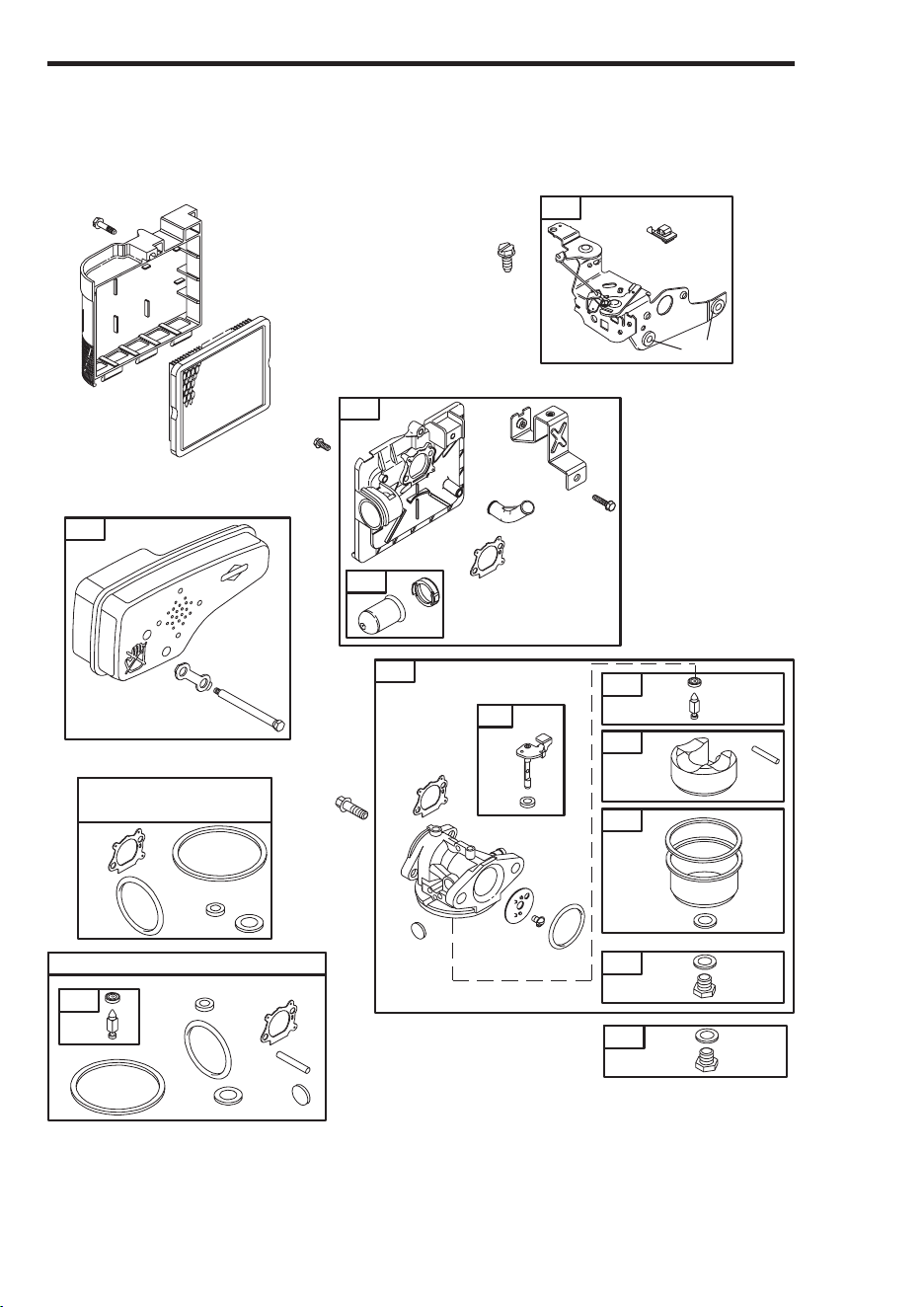
6
The operation of any lawn
mower can result in foreign
objects thrown into the
eyes, which can result in
severe eye damage. Always
wear safety glasses or eye shields while
operating your lawn mower or performing
any ad just ments or repairs. We recom-
mend standard safety glasses or a wide
vision safety mask worn over spectacles.
HOW TO USE YOUR LAWN MOWER
ENGINE SPEED
The engine speed is controlled by a
throttle control located on the side of the
upper handle. FAST position is for starting,
normal cutting, trimming and better grass
bagging. SLOW position is for light cut ting,
trimming and fuel econ o my.
LOWER WHEELS FOR HIGH CUT
RAISE WHEELS FOR LOW CUT
Plate tab
Lever
TO ADJUST CUTTING HEIGHT
Raise wheels for low cut and lower wheels
for high cut, adjust cutting height to suit
your requirements. Me di um position is
best for most lawns.
• To change cutting height, squeeze ad-
juster lever to ward wheel. Move wheel
up or down to suit your re quire ments. Be
sure all wheels are in the same setting.
NOTE: Adjuster is properly positioned
when plate tab inserts into hole in lever.
Also, 9-position adjusters (if so equipped)
allow lever to be positioned between the
plate tabs.
TO ENGAGE
DRIVE CONTROL
DRIVE
CONTROL
DISENGAGED
Operator presence control bar Drive
control
ENGINE ZONE CONTROL
CAUTION: Federal regulations re quire
an engine control to be installed on this
lawn mower in order to minimize the
risk of blade contact injury. Do not un der
any circumstances attempt to de feat the
func tion of the operator con trol. The blade
turns when the engine is running.
• Your lawn mower is equipped with an
operator pres ence control bar which
requires the operator to be positioned
behind the lawn mower handle to start
and operate the lawn mower.
DRIVE CONTROL
• Self-propelling is controlled by hold ing
the operator presence control bar down
to the handle and push ing the drive
control lever forward until it clicks; then
releasing the lever.
• Forward motion will stop when the op-
erator presence control bar is re leased.
To stop forward motion without stop ping
engine, re lease the operator presence
con trol bar slight ly until the drive control
dis en gag es. Hold op er a tor presence
control bar down against handle to con-
tin ue mowing without self-pro pel ling.
• To keep drive control engaged when
turning corners, push down on han dle
and lift front wheels off ground while
turning lawn mower.
SLOW
FAST
23
MODEL NUMBER 123K02-0183-E1
BRIGGS & STRATTON 4-CYCLE ENGINE
104
137
276
95
127
633
617
276
130
365
125
134
975
133
117
163
968
445
425
443
163
529
159
970
966
976
188
104
137
276
127
633
121 CARBURETOR OVERHAUL KIT
617
137
276
633
617
977 CARBURETOR
GASKET SET
163
163
134
81
613
300
668
621
222
276
118
97
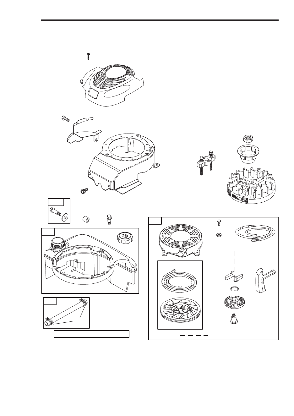
24
MODEL NUMBER 123K02-0183-E1
BRIGGS & STRATTON 4-CYCLE ENGINE
332
304
305
363
455
23
1036 EMISSIONS LABEL
55
456
58
60
459
689
597
608
65
592
921
969
190
670
957
972
1059
601
187
1211
1210
78
37
5
OPERATION
KNOW YOUR LAWN MOWER
READ THIS OWNER'S MANUAL AND ALL SAFETY RULES BEFORE OPERATING YOUR
LAWN MOWER. Compare the illustrations with your lawn mower to familiarize yourself with
the location of various controls and adjustments. Save this manual for future reference.
Starter
handle
Gasoline
fi ller cap
Housing
Wheel adjuster (on each wheel)
Handle knob
Grass
catcher
Engine oil cap
with dipstick
Operator presence control bar
Primer
MEETS CPSC SAFETY REQUIREMENTS
Sears rotary walk-behind power lawn mowers conform to the safety standards of the
American National Standards Institute and the U.S. Consumer Product Safety Com-
mis sion. The blade turns when the engine is running.
Operator presence control bar – must
be held down to the handle to start the
engine. Release to stop the engine.
Primer – pumps additional fuel from the
carburetor to the cylinder for use when
starting a cold engine.
Starter handle – used for starting engine.
These symbols may appear on your lawn mower or in literature supplied with the product.
Learn and understand their meaning.
IMPORTANT: This lawn mower
is shipped WITHOUT OIL OR
GASOLINE in the engine.
Drive control lever – used to engage
power-pro pelled forward mo tion of lawn
mower.
Throttle control – used for start ing the
engine and allows you to select either
FAST or SLOW engine speed.
Muffl er
Air fi lter
Drive control lever
Drive cover
Throttle
control
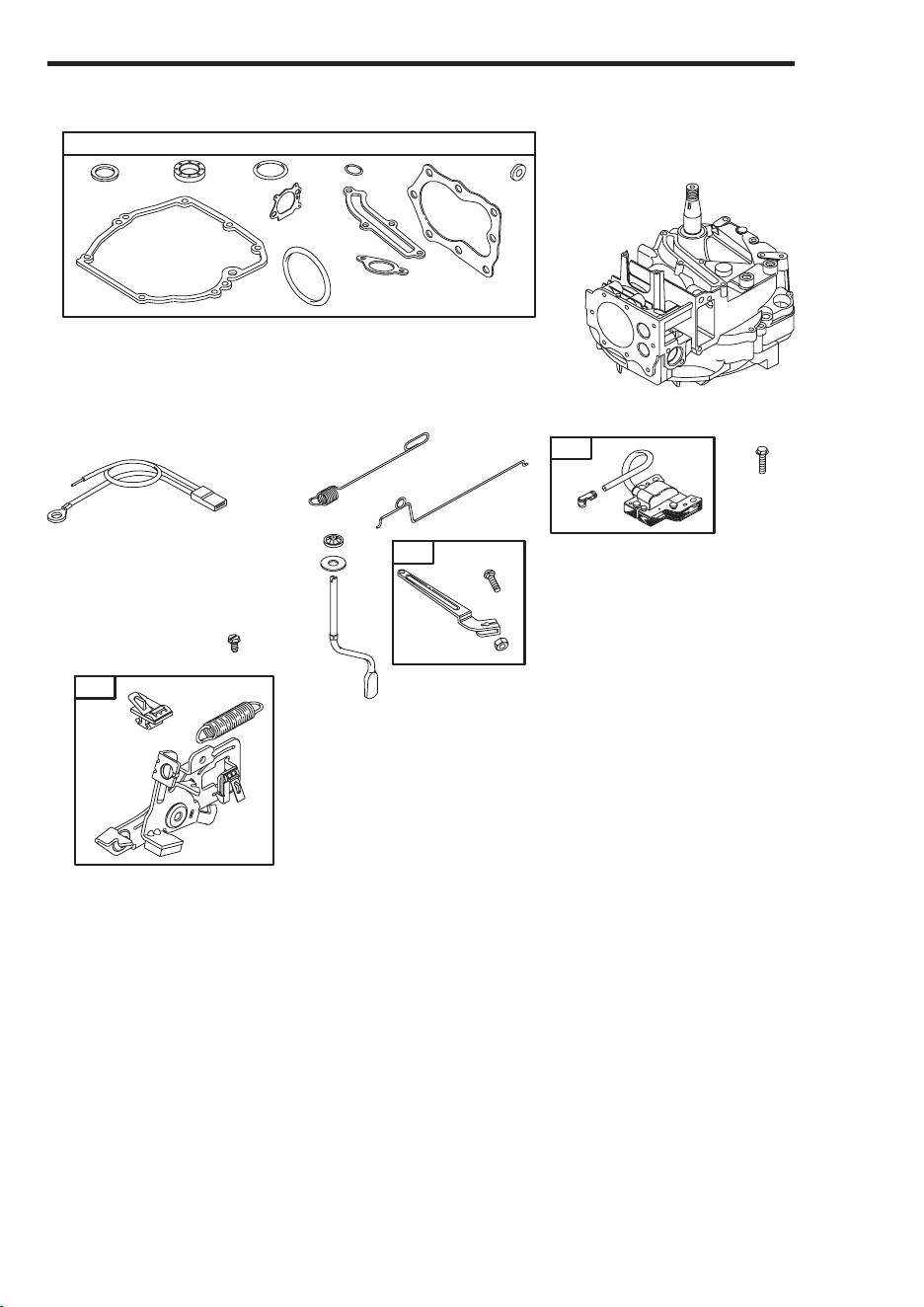
4
ASSEMBLY / PRE-OPERATION
Read these instructions and this manual in
its entirety before you attempt to assemble
or operate your new lawn mower.
IMPORTANT: This lawn mower is shipped
WITHOUT OIL OR GASOLINE in the engine.
Your new lawn mower has been as sem -
bled at the factory with the exception of
those parts left unassembled for shipping
purposes. All parts such as nuts, wash-
ers, bolts, etc., nec es sary to complete the
as sem bly have been placed in the parts
bag. To ensure safe and proper opera-
tion of your lawn mower, all parts and
hard ware you assemble must be tightened
securely. Use the correct tools as neces-
sary to ensure proper tightness.
TO REMOVE LAWN MOWER FROM
CAR TON
1. Remove loose parts included with mower.
2. Cut down two end corners of carton
and lay end panel down fl at.
3. Remove all packing materials except
padding between upper and lower
handle and padding holding operator
presence control bar to upper handle.
4. Roll lawn mower out of carton and
check carton thor ough ly for additional
loose parts.
HOW TO SET UP YOUR LAWN
MOW ER
TO UNFOLD HANDLE
IMPORTANT: Unfold handle carefully so
as not to pinch or damage con trol cables.
1. Raise handles until lower handle sec-
tion locks into place in mowing position.
2. Remove protective padding, raise up-
per handle sec tion into place on lower
handle and tighten both handle knobs.
3. Remove handle padding holding opera-
tor pres ence control bar to upper handle.
Your lawn mower handle can be adjusted
for your mowing comfort. Refer to “AD-
JUST HANDLE” in the Service and Adjust-
ments section of this manual.
TO ASSEMBLE GRASS CATCH ER
1. Put grass catcher frame into grass bag
with rigid part of bag on the bottom.
Make sure the frame handle is outside
of the bag top.
2. Slip vinyl bindings over frame.
NOTE: If vinyl bindings are too stiff, hold
them in warm water for a few minutes. If
bag gets wet, let it dry before using.
TO INSTALL ATTACHMENTS
Your lawn mower was shipped ready to be
used as a mulcher. To convert to bag-
ging, see “TO CON VERT MOW ER” in the
Operation section of this man u al.
Mowing
position
Lower handle
LIFT
UP
Operator presence
control bar
Upper handle
LIFT UP
Catcher
frame
handle
Vinyl
bindings
Frame
opening
25
MODEL NUMBER 123K02-0183-E1
BRIGGS & STRATTON 4-CYCLE ENGINE
334
851
333
202
209
356
562
505
227
616
404
615
922
621
923
358 ENGINE GASKET SET
12
3
20
51
585
7
163
524
668
842
48
617
745
KEY PART
NO. NO. DESCRIPTION
1 697322 Cylinder Assembly
2 399269 Kit, Bushing/Seal
3 299819 • Seal, Oil, Magneto Side
4 493279 Sump, Engine
5 691160 Head, Cylinder
7 692249 • Gasket, Cylinder Head
8 695250 Breather Assembly
9 696125 Gasket, Breather
10 691125 Screw, Breather Assembly
11 691781 Tube, Breather
12 692232 • Gasket, Crankcase
13 690912 Screw, Cylinder Head
15 691680 Plug, Oil Drain
16 691451 Crankshaft
KEY PART
NO. NO. DESCRIPTION
20 399781 • Seal, Oil, PTO Side
22 691092 Screw, Engine Sump
23 692315 Flywheel
24 222698 Key, Flywheel
25 697339 Piston Assembly, Standard
697340 Piston Assembly, .010" Oversize
697341 Piston Assembly, .020" Oversize
697342 Piston Assembly, .030" Oversize
26 499425 Ring Set, Piston, Standard
499426 Ring Set, Piston, .010" Oversize
499427 Ring Set, Piston, .020" Oversize
499428 Ring Set, Piston, .030" Oversize
27 691866 Lock, Piston Pin
28 499423 Pin, Piston

26
MODEL NUMBER 123K02-0183-E1
BRIGGS & STRATTON 4-CYCLE ENGINE
KEY PART
NO. NO. DESCRIPTION
29 499424 Rod, Connecting
32 691664 Screw, Connecting Rod
32A 695759 Screw, Connecting Rod
33 262651 Valve, Exhaust
34 262652 Valve, Intake
35 691270 Spring, Valve, Intake
36 691270 Spring, Valve, Exhaust
37 694086 Guard, Flywheel
40 692194 Retainer, Valve
43 691997 Slinger, Governor/Oil
45 690548 Tappet, Valve
46 691449 Camshaft
48 498826 Short Block (Replacement Engine,
Model Number 123K02-0015-E1)
50 497465 Manifold, Intake
51 272199 • Gasket, Intake
54 691650 Screw, Intake Manifold
55 691421 Housing, Rewind Starter
58 692259 Rope, Starter (Cut to Length)
60 281434 Grip, Starter Rope
65 690837 Screw, Rewind Starter
78 691108 Screw, Flywheel Guard
81 691740 Lock, Muffl er Screw
95 691636 Screw, Throttle Valve
97 696565 Shaft, Throttle
104 691242 Ø Pin, Float Hinge
117 498978 Jet, Main, Standard
118 497466 Jet, Main, High Altitude
121 498260 Kit, Carburetor Overhaul
125 498170 Carburetor
127 694468 Ø Plug, Welch
130 696564 Valve, Throttle
133 398187 Float, Carburetor
134 398188 Ø Valve, Needle/Seat
137 693981 ؇ Gasket-Float Bowl
146 690979 Key, Timing
159 691753 Bracket, Air Cleaner Primer
163 272653 •Ø‡ Gasket, Air Cleaner
187 691050 Line,Fuel (Cut to Required Length)
188 693399 Screw, Control Bracket
190 690940 Screw, Fuel Tank
202 691829 Link, Mechanical Governor
209 690319 Spring, Governor
222 692031 Bracket, Control
227 690783 Control Lever-Governor
276 271716 ؇ Sealing Washer
287 690940 Screw (Dipstick Tube
300 692038 Muffl er
304 695892 Housing, Blower
305 691108 Screw, Blower Housing
306 690450 Shield, Cylinder
307 690345 Screw, Cylinder Shield
332 690662 Nut, Flywheel
333 802574 Armature, Magneto
334 691061 Screw, Armature
337 802592 Spark Plug
356 692390 Wire, Stop
358 497316 Engine Gasket Set
363 19069 Flywheel Puller
365 692524 Screw, Carburetor
383 89838 Wrench, Spark Plug
404 690272 Washer, Governor Crank
425 690670 Screw, Air Cleaner Cover
443 692523 Screw, Air Cleaner Primer Base
445 491588 Filter, Air Cleaner Cartridge
KEY PART
NO. NO. DESCRIPTION
455 691219 Cup, Flywheel
456 692299 Plate, Pawl Friction
459 281505 Pawl, Ratchet
505 231082 Nut, Governor Control Lever
523 495264 Dipstick
524 692296 • Seal, Dipstick Tube
525 495265 Tube, Dipstick
529 691923 Grommet
562 92613 Bolt, Governor Control Lever
584 692342 Cover, Breather Passage
585 691879 • Gasket, Breather Passage
592 690800 Nut, Rewind Starter
597 691696 Screw, Pawl Friction Plate
601 95162 Clamp, Hose
608 497680 Starter, Rewind
613 691340 Screw, Muffl er
615 690340 Retainer, Governor Shaft
616 691308 Crank, Governor
617 270344 •Ø‡ Seal, O-Ring, Intake Manifold
621 692310 Switch, Stop
633 691321 ؇ Seal, Throttle Shaft
635 66538 Boot, Spark Plug
668 493823 • Spacer (Includes 2)
670 692294 Spacer, Fuel Tank
684 690345 Screw, Breather Passage Cover
689 691855 Spring, Friction
718 690959 Pin, Locating
741 691830 Gear, Timing
745 691648 Screw, Brake
842 691031 • Seal, O-Ring, Dipstick Tube
847 692017 Assembly, Dipstick/Tube
851 493880 Terminal, Spark Plug
868 697338 Seal, Valve
869 691155 Seat, Valve, Intake
870 690380 Seat, Valve, Exhaust
871 262001 Bushing, Guide, Exhaust
63709 Bushing, Guide, Intake
921 697343 Cover, Blower Housing
922 692135 Spring, Brake
923 695891 Brake
957 397974 Cap, Fuel Tank
966 496116 Base, Air Cleaner Primer
968 692298 Cover, Air Cleaner
969 690700 Screw, Blower Housing Cover
970 691669 Screw, Air Cleaner Primer Bracket
972 495224 Tank, Fuel
975 493640 Bowl, Float
976 694395 Primer, Carburetor
977 498261 Set, Carburetor Gasket
1019 494256 Kit, Label
1036 697456 Label, Emissions
1059 692311 Kit, Screw/Washer
1210 498144 Assembly, Pulley/Spring (Pulley)
1211 498144 Assembly, Pulley/Spring (Spring)
RPM Settings: Low Speed: 1900-2100
High Speed: 3000-3200
• Included in Engine Gasket Set, Key #358
Ø Included in Carburetor Overhaul Kit, Key #121
‡ Included in Carburetor Gasket Set, Key #977
NOTE: All component dimensions given in U.S. inches
1 inch = 25.4 mm
3
• Do not operate the mower when bare-
foot or wearing open sandals. Al ways
wear substantial foot wear.
• Do not pull mower backwards unless abso-
lutely nec es sary. Always look down and be-
hind before and while moving backwards.
• Do not operate the mower without
proper guards, plates, grass catcher or
oth er safety protective devices in place.
• See manufacturer’s instructions for
proper operation and installation of
accessories. Only use accessories ap-
proved by the manufacturer.
• Stop the blade(s) when crossing grav el
drives, walks, or roads.
• Stop the engine (motor) whenever you
leave the equip ment, before clean ing
the mower or unclogging the chute.
• Shut the engine (motor) off and wait
until the blade comes to complete stop
before removing grass catcher.
• Mow only in daylight or good artifi cial light.
• Do not operate the machine while under
the infl uence of alcohol or drugs.
• Never operate machine in wet grass. Al-
ways be sure of your footing: keep a fi rm
hold on the handle and walk; never run.
• Disengage the self-propelled mech a nism
or drive clutch on mowers so equipped
before starting the engine (motor).
• If the equipment should start to vi brate
abnormally, stop the engine (motor) and
check immediately for the cause. Vibra-
tion is generally a warning of trouble.
• Always wear safety goggles or safe ty glass-
es with side shields when op er at ing mower.
II. SLOPE OPERATION
Slopes are a major factor related to slip
and fall accidents which can result in
severe injury. All slopes require extra cau-
tion. If you feel uneasy on a slope, do not
mow it.
• Mow across the face of slopes: nev er
up and down. Exercise extreme caution
when changing direction on slopes.
• Remove obstacles such as rocks, tree
limbs, etc.
• Watch for holes, ruts, or bumps. Tall
grass can hide obstacles.
DO NOT:
• Do not trim near drop-offs, ditches or
embankments. The operator could lose
footing or balance.
• Do not trim excessively steep slopes.
• Do not mow on wet grass. Reduced
footing could cause slipping.
III. CHILDREN
Tragic accidents can occur if the op er a tor is
not alert to the presence of children. Children
are often attracted to the ma chine and the
mowing activity.
Never
assume that children
will remain where you last saw them.
• Keep children out of the trimming area
and under the watchful care of an oth er
re spon si ble adult.
• Be alert and turn machine off if chil dren
enter the area.
• Before and while walking back wards,
look behind and
down
for small chil dren.
• Never allow children to operate the machine.
• Use extra care when approaching blind
corners, shrubs, trees, or other objects
that may obscure vision.
IV. SERVICE
• Use extra care in handling gasoline and
other fuels. They are fl ammable and
vapors are explosive.
- Use only an approved container.
- Never remove gas cap or add fuel
with the engine running. Allow engine
to cool before refueling. Do not smoke.
- Never refuel the machine indoors.
- Never store the machine or fuel
container inside where there is an
open fl ame, such as a water heater.
• Never run a machine inside a closed area.
• Never make adjustments or repairs with
the engine (motor) running. Dis con nect the
spark plug wire, and keep the wire away
from the plug to prevent ac ci den tal starting.
• Keep nuts and bolts, especially blade
attachment bolts, tight and keep equip-
ment in good condition.
• Never tamper with safety devices. Check
their proper operation regularly.
• Keep machine free of grass, leaves, or
other debris build-up. Clean oil or fuel spill-
age. Allow machine to cool before storing.
• Stop and inspect the equipment if you
strike an object. Repair, if nec es sary,
before restarting.
• Never attempt to make wheel height adjust-
ments while the engine (mo tor) is running.
• Grass catcher components are sub ject
to wear, dam age, and de te ri o ra tion,
which could expose moving parts or
allow objects to be thrown. Frequently
check com po nents and replace with
man u fac tur er’s recommended parts,
when necessary.
• Mower blades are sharp and can cut.
Wrap the blade(s) or wear gloves, and
use extra caution when ser vic ing them.
• Do not change the engine governor set-
ting or overspeed the engine.

2
Warranty .................................................. 2
Safety Rules ......................................... 2-4
Assembly/Pre-Operation ......................... 4
Operation.............................................. 5-8
Maintenance Schedule............................ 9
Maintenance....................................... 9-12
Product Spec i fi ca tions ......................... 10
Service and Adjustments.................. 12-13
Storage............................................. 14-15
Troubleshooting ................................ 15-16
Repair Parts...................................... 17-26
Sears Service .......................... Back Cover
TABLE OF CONTENTS
SAFETY RULES
I. GENERAL OPERATION
• Read, understand, and follow all
in struc tions on the machine and in the
manual(s) before starting. Be thor ough ly
familiar with the controls and the proper
use of the machine before starting.
• Do not put hands or feet near or under
rotating parts. Keep clear of the dis-
charge opening at all times.
• Only allow responsible individuals, who
are familiar with the in struc tions, to
operate the machine.
• Clear the area of objects such as rocks,
toys, wire, bones, sticks, etc., which
could be picked up and thrown by the
blade.
• Be sure the area is clear of other people
before mowing. Stop ma chine if anyone
enters the area.
IMPORTANT: This cutting machine is capable of amputating hands and feet and throwing ob-
jects. Failure to observe the following safety instructions could result in serious injury or death.
Look for this symbol to point out
im por tant safety precautions. It means
CAU TION!!! BECOME ALERT!!! YOUR
SAFE TY IS INVOLVED.
CAUTION: Always disconnect spark
plug wire and place wire where it cannot
contact spark plug in order to prevent
ac ci den tal starting when setting up,
trans port ing, adjusting or making repairs.
CAUTION: Muffl er and other engine
parts become extremely hot during
operation and remain hot after engine has
stopped. To avoid severe burns on contact,
stay away from these areas.
LIMITED TWO YEAR WARRANTY ON CRAFTSMAN POWER MOWER
For Two years from date of purchase Sears Canada, Inc. will repair or replace at Sears
option free of charge parts which are defective as a result of material or workmanship.
COMMERCIAL OR RENTAL USE:
Warranty on Power Mower (Gas) will be ninety (90) days from date of purchase if used
for commercial or rental purposes.
This Warranty does NOT
cover:
• Pre-delivery set-up.
• Expendable items which become worn during normal use, such as rotary mower
blades, blade adapters, belts, air clean ers and spark plug.
• Repairs necessary because of operator abuse or neg li gence, including bent crank-
shafts and the failure to main tain the equip ment according to the instructions con tained
in the owner’s manual.
Warranty service is available by returning the Craftsman Power Mower to the nearest
Sears Service Centre/Department in Canada. This warranty applies only while this prod-
uct is used in Canada.
This warranty is in addition to any statutory warranty and does not exclude or limit legal
rights you may have but shall run con cur rent ly with applicable provincial legislation. Fur-
thermore, some provinces do NOT allow limitation on how long an implied warranty will
last so the above limitations may not apply to you.
SEARS CANADA, INC., TORONTO, ONTARIO M5B 2B8
WARRANTY
27
SERVICE NOTES

181989 Rev. 2 10.08.02 BY Printed in U.S.A.
Model No.
944.362310
CAUTION:
Read and follow all
Safety Rules and In struc tions
before operating this equipment
Owner’s Manual
ROTARY LAWN MOWER
6.5 Horsepower
Power-Propelled
21" Rear Discharge
Sears Canada, Inc., Toronto, Ontario M5B 2B8