
4
Contents
Contents
Chapter 1 Specification ............................................. 8
1-1 SL-865Pro2-FGR Mainboard Layout ...................................9
1-2 Chipset System Block Diagram........................................... 10
1-3 Mainboard Specification Table ............................................11
1-4 Mainboard Specifications .................................................... 12
1-4.1 CPU Socket ................................................................................... 12
1-4.2 System Chipsets ........................................................................... 12
1-4.3 Memory .........................................................................................12
1-4.4 AMI BIOS ..................................................................................... 12
1-4.5 Accelerated Graphics Port (AGP) Interface........................... 13
1-4.6 Advanced System Power Management .................................... 13
1-4.7 Multi-I/O Functions :.................................................................. 13
1-4.8 Expansion Slots ............................................................................ 13
1-4.9 Gigabit Ethernet Controller on board ..................................... 14
1-4.10 Hardware Monitor on board ................................................... 14
1-4.11 6-channel AC’97 Audio Codec on board .............................. 14
1-4.12 Serial ATA Interface integrated .............................................. 14
1-4.13 Parallel ATA RAID Interface integrated ...............................14
1-4.14 IEEE 1394A Interface ............................................................... 14
1-4.15 Form Factor................................................................................ 14
Chapter 2 Hardware Setup ..................................... 16
2-1 CPU Installation with Socket 478B .................................... 17
2-1.1 To Identify a Pentium 4 CPU.....................................................17
2-1.2 CPU Installation with Socket 478B .......................................... 18
2-2 Pentium 4 CPU Fan Installation: ....................................... 19
2-2 Memory Installation ............................................................. 20
2-2.1 To Install DDR SDRAM Module .............................................. 20
2-2.2 Dual Channel Memory Module Installation ........................... 21
2-2.3 To Remove a DIMM .................................................................... 21
2-3 AGP 8X/4X Slot Installation ................................................ 22
2-4 IDE Connectors Installation................................................ 23
2-5 Serial ATA Connectors Installation .................................... 24
2-6 Floppy Drive Connector Installation ................................. 25
2-7 ATX V2.03 Power Supply Installation ............................... 26
2-8 Jumper Settings ..................................................................... 27

5
Contents
2-8.1 JFSB1 & JFSB2: CPU Frequency Select................................. 28
2-8.2 JBAT1: Clear CMOS .................................................................. 29
2-8.3 (Optional) JFSB3: Memory Turbo Mode ................................ 30
2-8.4 JKB1: Keyboard / Mouse Wake Up ......................................... 30
2-9 Other Connectors Configuration........................................ 31
2-9.1 On Board Fan Connectors ......................................................... 31
2-9.2 USB Ports and USB Pin-headers ..............................................32
2-9.3 Chassis Panel Connectors .......................................................... 33
2-9.4 CD-ROM Audio Connectors...................................................... 33
2-9.5 PS/2 Mouse And PS/2 Keyboard ............................................... 34
2-9.6 External Audio Connector ........................................................ 34
2-9.7 1394A Connector.......................................................................... 34
2-9.8 LAN Connector ............................................................................ 35
2-9.9 Thermal Detector.........................................................................35
2-9.10 Complex Pin-header (Front Panel Connectors)................... 36
2-9.11 LED1: Debug LED .................................................................... 37
Chapter 3 Software Setup ....................................... 38
3-1 To Open up the Support CD ................................................ 38
3-2 Intel Chipset Software Installation Utility........................ 39
3-3 AC’97 Audio Driver Installation......................................... 40
3-3.1 Install AC’97 6-channel Audio Driver ..................................... 40
3-3.2 Verifying 6-channel Audio..........................................................41
3-4 To install Gigabit Ethernet Drivers.................................... 44
3-4.1 Installation ...................................................................................44
3-4.2 Verification .................................................................................. 44
3-5 To Install Hardware Monitor Utility.................................. 45
3-5.1 Installation ...................................................................................45
3-5.2 Verification .................................................................................. 46
3-6 To Install USB 2.0 Driver for Windows 2000/XP ............. 47
3-7 To Install RAID Controller Driver ..................................... 47
Chapter 4 AMI BIOS Setup.................................... 48
4-1 About BIOS Setup ................................................................. 49
4-2 To Run BIOS Setup ............................................................... 49
4-3 About CMOS .......................................................................... 49
4-4 The POST ( Power On Self Test ) ....................................... 49
4-5 To Update BIOS ..................................................................... 50
4-6 BIOS SETUP --- CMOS Setup Utility................................ 52
4-6.1 CMOS Setup Utility ....................................................................52
4-6.2 Standard BIOS Features ............................................................ 54
4-6.3 Advanced BIOS Features ........................................................... 55
4-6.3.1 CPU Configuration................................................................... 56

6
Contents
4-6.3.2 IDE Configuration.................................................................... 57
4-6.3.3 Floppy Configuration ............................................................... 60
4-6.3.4 Super IO Configuration ........................................................... 61
4-6.3.5 Hardware Health Configuration............................................. 63
4-6.3.6 ACPI Configuration ................................................................. 64
4-6.3.7. Clock Generator Configuration ............................................. 66
4-6.3.8. USB Configuration .................................................................. 67
4-6.3.9. Voltage Control ........................................................................ 68
4-6.3.10. Power Management ............................................................... 69
4-6.3.11. PCI Device Control................................................................ 70
4-6.4 Advanced Chipset Features ....................................................... 71
4-6.4.1 NorthBridge Configuration ..................................................... 72
4-6.4.2 SouthBridge Configuration ..................................................... 74
4-6.5 PCI/PNP Resource Management .............................................. 75
4-6.6 Boot Configuration Features ..................................................... 76
4-6.6.1 Boot Settings Configuration .................................................... 77
4-6.6.2 Boot Device Priority ................................................................. 78
4-6.7. Boot Security Features .............................................................. 79
4-6.7.1. Supervisor Password ............................................................... 79
4-6.7.2. User Password.......................................................................... 79
4-6.7.3 Change Supervisor Password .................................................. 80
4-6.7.4 Change User Password ............................................................ 81
4-6.7.5. Clear User Password ............................................................... 81
4-6.7.6 Boot Sector Virus Protection ................................................... 82
4-6.8 Load Optimal Defaults ............................................................... 82
4-6.9 Discard Changes .......................................................................... 83
4-6.10 Save Changes and Exit ............................................................. 83
4-6.11 Discard Changes and Exit ........................................................ 83
Chapter 5 RAID & RAID Driver ........................... 84
5-0 About Disk Array................................................................... 85
5-0-1 Disk Array Interpretation.......................................................... 85
5-0-2 Disk Array Member .................................................................... 85
5-0-3 Disk Array Types Supported by PDC20378 ........................... 85
5-1. SATA RAID and PATA RAID Layout on Board ............. 86
5-2. To Enter RAID Setup Utility .............................................. 86
5-3. First Step to Set up RAID - Populate Disk Drives.......... 86
5-4. To Enter the Main Menu of FastBuild Utility ................. 87
5-5. View Drive Assignment before RAID Setup .................... 88
5-6. Enter “Auto Setup” for RAID Setup ................................ 88
5-7. Choose “ Security” for RAID 0+1 (Stripe/Mirror) ........ 89
5-8. Press <Ctrl-Y> to Save the Choice .................................... 89
5-9. Create RAID Only / Create and Quick Initialize ........... 90

7
Contents
5-10. Array Created and View Drives Assignments ............... 90
5-11. Enter [Define Array] to see the RAID Mode ................. 91
5-12. After Array creation, press [Esc] to exit......................... 91
5-13. To Install Promise RAID Driver ...................................... 92
5-13-1 To Install RAID Driver on Windows 2000/XP/2003 ........... 92
5-13-2 To Install RAID Driver on Windows 98SE/Me .................... 95
APPENDICES.......................................................... 98
Appendix-1 Identify Mainboard Model Number ................... 99
Appendix-2 Technical Terms .................................................... 100
Appendix-3 AMI BIOS CheckPoint and Beep Code List.... 107

8
SL-865Pro2-FGR
Introduction
Chapter 1 Specification
This mainboard of mainboards features an integration of the power-
ful Intel 478-pin Pentium 4 CPU and the North Bridge Intel 865PE. The
Pentium 4 CPU is a rapid execution engine providing 800/533/400MHz
system bus, while North Bridge Intel 865PE is a high performance inte-
grated chipset providing Dual Channel DDR 400/333/266 SDRAM
memory interface, Hub interface as well as AGP 8x/4x interface.
Integrated with Intel 865PE, South Bridge Intel ICH5 supports the
LPC I/O, upstream Hub interface, IDE interface, PCI bus (supporting
PCI interface,Serial ATA interface, IEEE 1394 interface), AC’97 2.2 (6-
channel) Audio interface, USB 2.0 and the interrupt control. This chap-
ter is to introduce to users every advanced function of this high perfor-
mance integration.
** If any difference is found between the mainboard description
and the Mainboard you are using, please look up the Errata/
Update Slip enclosed inside for the correction or updated
information, or else contact the mainboard Dealer or visit our
Web Site for the latest manual update.
1-1 SL-865Pro2-FGR Mainboard Layout ...................................9
1-2 Chipset System Block Diagram........................................... 10
1-3 Mainboard Specification Table ............................................11
1-4 Mainboard Specifications .................................................... 12
1-4.1 CPU Socket ................................................................................... 12
1-4.2 System Chipsets ........................................................................... 12
1-4.3 Memory .........................................................................................12
1-4.4 AMI BIOS ..................................................................................... 12
1-4.5 Accelerated Graphics Port (AGP) Interface........................... 13
1-4.6 Advanced System Power Management .................................... 13
1-4.7 Multi-I/O Functions :.................................................................. 13
1-4.8 Expansion Slots ............................................................................ 13
1-4.9 Gigabit Ethernet Controller on board ..................................... 14
1-4.10 Hardware Monitor on board ................................................... 14
1-4.11 6-channel AC’97 Audio Codec on board .............................. 14
1-4.12 Serial ATA Interface integrated .............................................. 14
1-4.13 Parallel ATA RAID Interface integrated ...............................14
1-4.14 IEEE 1394A Interface ............................................................... 14
1-4.15 Form Factor................................................................................ 14
9
Chapter 1 Specification
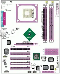
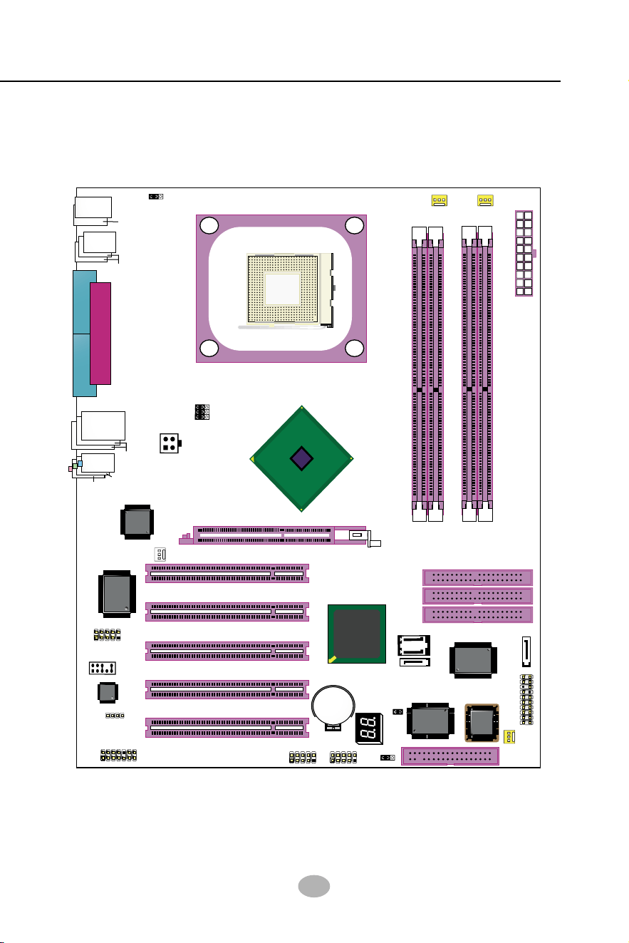
1-1 SL-865Pro2-FGR Mainboard Layout
865PE
Intel
Intel 82865PE
BIOS
RTL
ALC655
LPT1
COM1
COM2
mPGA478B
PW1
+12V Power
HDD
IR
PWR
1
20
SPK RST
+
-
+
-
PWLED
LED
Fan1
1
USB3
RJ45
(on top)
AGP1 (8X/4X)
ICH5
Intel
IDE1
IDE2
IDE3
FDC1
PCI1
PCI2
PCI3
PCI4
PCI5
for Dual-channel DDR 400/333/266MHz
Fan2
PW2
1
JKB1
1
JBAT1
1
JFSB2
JFSB1
PS/2 Mouse
(on top)
PS/2 Keyboard
(
m
id
d
le
)
JAUD1
1
L
in
e
in
(
o
n
t
o
p
)
L
in
e
O
u
t
(
u
n
d
e
r
s
id
e
)
M
ic
1
CD_IN1
VT6307
VIA
W83627HF
Winbond
USB4
DIMM1 DIMM2
DIMM3 DIMM4
SATA1
SATA2
PDC20378
Promise
1
USB2
USB1(2 ports)
1
IEEE1
10
Fan3
IEEE
1394
VIA
VT6122
Li
Battery
JFSB3
ATA1
AUDIO1
Main Power
Fan4
(2 ports)
RT3
82801EB
22
1
2
2
2
10
(underside)
LED1
10
SL-865Pro2-FGR
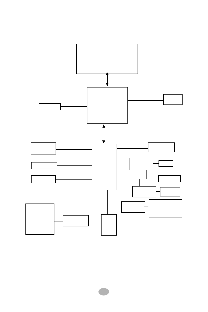
Prescott CPU + Intel 865PE + Intel ICH5 Diagram
System Bus 800/533/400MHz
865PE
Intel
ICH5
PCI Bus
AC’97 2.2ATA 100/66/332 IDE
USB Bus V2.0
5 PCI Slots
Audio Codec
(6-channel)
VT6122
RJ45
IR
FDD
Mouse/Keyboard
Serial Ports
Printer Port
H/Monitor
BIOS
LPC I/O
W83627HF
1-2 Chipset System Block Diagram
System
Memory
Dual Channel
DDR 400/
333/266
SDRAM
Intel
North Bridge
2 SATA ports
Serial ATA
AGP Slot
AGP 8X/4X
Intel P4 478-pin
Prescott(3.2GHz)/
Hyper-threading/
Celeron CPU
South
Bridge
connectors
8 USB ports
1 PATA 133 RAID
VIA
2 x1394A
VT6307
Promise
2 SATA RAID
PDC20378
ports
Gigabit LAN
connectors
connector;

11
Chapter 1 Specification
1-3 Mainboard Specification Table
CPU
Pentium 4 Prescott (up to 3.2GHz)/Hyper-
threading/Celeron CPUs
SL-865Pro2-FGR Specifications and Features
IEEE 1394A , Promise RAID and GiGa LAN are
enabled/disabled by BIOS setup (See PCI Device
Control in Advanced Features of BIOS Setup).
Gigabit Ethernet Controller VIA VT6122
8 USB V2.0, 1 FDD port, 2 COM ports, 1 LPT,
1 IrDA, 1 PS/2 K/B, 1 PS/2 Mouse
5 PCI Master slots on board
2 SATA RAID connectors supported by PDC20378
2 UATA 66/100 IDE ports;
1 UATA 133 IDE port for IDE RAID Hard Disk
AC’97 Audio 2.2 compliant, 6 channel audio
AGP8X/4X Mode only; 1 AGP Slot on board
W83627HF, with Hardware Monitor
Supporting Dual-channel DDR 400/333/266
SDRAM, up to 4GB in 4 DIMM slots
AMI BIOS
Intel ICH5
Intel 865PE, supporting 800/533/400MHz FSB
Other common
features
Networking
I/O Connectors
PCI Slots
SATA RAID
Interface
IDE Interface
Audio
I/O Chip
AGP interface
Memory
BIOS
South Bridge
North Bridge
2 SATA connectors supported by ICH5;
SATA Interface

12
SL-865Pro2-FGR
1-4 Mainboard Specifications
1-4.1 CPU Socket
CPU Socket 478 on board, supporting Intel
®
Pentium 4 Prescott(Up to
3.2GHz) /Hper-threading/Celeron CPUs in 478-pin package for :
-- 800/533/400MHz System Bus
-- Hyper-pipelined technology -- Advanced dynamic execution;
-- Rapid Execution Engine -- Streaming SIMD Extensions 2/3
-- 128 Bit Enhanced Floating Point Unit -- Execution Trace Cache
1-4.2 System Chipsets
North Bridge Intel 865PE:
• A high performance integrated chipset supporting Hyper-Threading
Technology, Dual channel DDR 400/333/266 SDRAM memory
interface, Hub interface, AGP interface.
• Showing Hyper Threading Logo when booting with a Hyper-thread-
ing CPU.
South Bridge Intel ICH5:
• Supporting the LPC I/O, upstream Hub interface, PCI bus
(supporting Serial ATA, IEEE 1394 and GiGaLAN), IDE interface and
USB 2.0 interface, and AC’97 2.2 (6-channel) Audio interface.
1-4.3 Memory
4 DDR DIMM 184-pin slots on board :
• Supporting unregistered, non-ECC Dual-channel DDR 400/333/266
SDRAM up to 4GBs
• DIMMs to be populated in identical pairs for Dual-channel operation
• SPD (Serial Presence Detect) Scheme for DIMM Detection supported
1-4.4 AMI BIOS
Flash Memory for easy upgrade, supporting BIOS Writing Protection,
Year 2000 compliant, and supporting various hardware configuration
during booting system (See Chapter 4 BIOS Setup):
• Standard BIOS Features(Times, Date, System Information etc.)
• Advanced BIOS Features (CPU,IDE, Floppy, Super I/O, Hardware
Health, ACPI, USB, and Frequency/Voltage Control)
• Advanced Chipset Features (NorthBridge, SouthBridge Configuration)
• PCI/PNP Resource Management (IRQ Settings, Latency Timers etc.)
• Boot Configuration Setup (Boot Settings, Boot Device Priority etc.)
• BIOS Security Features (Supervisor Password, User Password)

13
Chapter 1 Specification
1-4.7 Multi-I/O Functions :
• Serial ATA Controller integrated in ICH5, supporting:
-- 2x Serial ATA connectors supporting up to 150MByte/s transfer rate
• PCI EIDE Controller, supporting:
-- 2x UATA100/66/33 IDE connectors supporting up to 4 IDE devices
• Dedicated IR Functions:
-- Third serial port dedicated to IR function either through the two
complete serial ports or the third dedicated port Infrared-IrDA (HPSIR)
and ASK (Amplitude Shift Keyed) IR
• Multi-mode Parallel Data Transfer:
-- Standard mode, high speed mode ECP and enhanced mode EPP
• Floppy Disk Connector:
-- One FDD connector supporting 2 floppy drives with drive swap support
• Universal Serial Bus Transfer Mode:
-- USB V2.0 compliant; 480Mb/s USB Bus, supporting Windows 2000 or
later operating system (no support for Windows 9X/ME)
-- 4 built-in USB connectors and 2 USB Headers which require 2 additional
USB cables to provide 4 more optional USB ports
• PS/2 Keyboard and PS/2 Mouse
• UARTs (Universal Asynchronous Receiver / Transmitter):
-- Two serial ports (COM1 & COM2) on board
1-4.6 Advanced System Power Management
• ACPI 1.0B compliant (Advanced Configuration and Power Interface),
including ACPI suspend mode support (See ACPI Configuration of
Advanced BIOS Features in BIOS Setup)
• APM V1.2 compliant (Legacy Power Management) supporting vari-
ous Resume-from-suspend functions (See Power management in Ad-
vanced BIOS Features of BIOS Setup.)
1-4.5 Accelerated Graphics Port (AGP) Interface
AGP Controller embedded on board, supporting:
• 1.5V (4x/8x) power mode only
• 8x 66MHz AD and SBA signalling, AGP pipelined split-transection
longburst transfers up to 2GB/sec
• AGP 8X/4X supported, AGP V3.0 compliant
1-4.8 Expansion Slots
• 5 PCI Bus Master slots
• 1 AGP8X/4X slot
• 4 DDR SDRAM DIMM slots

14
SL-865Pro2-FGR
1-4.11 6-channel AC’97 Audio Codec on board
AC’97 Audio Codec 2.2 compliant on board
• Supporting 6-channel display of PCM audio output
• 6 channel audio consists of Front Left, Front Right, Back Left, Back
Right, Center and Subwoofer for complete surround sound effect
• AC’97 Audio Codec Driver enclosed in Support CD for user’s
installation.
1-4.9 Gigabit Ethernet Controller on board
PCI local bus single-chip Gigabit Ethernet Controller VIA VT6122 on
board:
• Supporting 10/100/1000Mb data transfer
• Supporting Wake On LAN function through the on-board RJ45 LAN
Connector
• LAN Driver enclosed in Support CD for user’s installation.
1-4.10 Hardware Monitor on board
• Hardware Monitor supported by W83627HF, providing monitoring and
alarm for flexible desktop management of hardware voltage, tempera-
tures and fan speeds.
• Utility Software Soltek Hardware Monitor for displaying system status
is enclosed in Support CD for user’s installation.
1-4.15 Form Factor
• ATX Form Factor, ATX Power Supply, version 2.03 compliant, sup-
ported by one Main Power Connector, one +12V Power Connector.
• Mainboard size: 305mm x 245mm
1-4.12 Serial ATA Interface integrated
• 2 SATA connectors supported by ICH5 for two SATA Hard Disk setup
• 2 SATA connectors supported by Promise PDC20378 for two SATA
RAID hard Disks setup
• SATA interface supporting transfer speed up to 150MB/sec.
1-4.13 Parallel ATA RAID Interface integrated
• 1 Parallel ATA IDE connector supported by Promise PDC20378 for
two IDE RAID Hard Disks setup, transfer speed up to 133MB/sec.
1-4.14 IEEE 1394A Interface
• PCI-bus based open host controller, compliant with IEEE 1394a stan-
dard for high performance serial bus
• Supporting 400/200/100 Mbits transfer rate.
• 2 IEEE 1394A ports supported by IEEE1394A controller VT6307

15
Chapter 1 Specification
Memo

16
SL-865Pro2-FGR
Chapter 2 Hardware Setup
1. We recommend to install your CPU before any other components.
For detailed installation instructions of processor, you can also refer
to the pamphlet enclosed in your CPU package.
2. Installing a cooling fan with a good heat sink is a must for proper
heat dissipation for your CPU. Get ready an appropriate fan with
heat sink for proper installation. Improper fan and installation will
damage your CPU.
3. In case CPU Vcore, CPU clock or Frequency Ratio is adjustable on
board, please follow the instructions described in the User’s manual
for proper setup. Incorrect setting will cause damage to your CPU.
The following topics are included in this chapter:
To Get Things Ready for Hardware Setup !
2-1 CPU Installation with Socket 478B .................................... 17
2-1.1 To Identify a Pentium 4 CPU..................................................... 17
2-1.2 CPU Installation with Socket 478B .......................................... 18
2-2 Pentium 4 CPU Fan Installation: ....................................... 19
2-2 Memory Installation ............................................................. 20
2-2.1 To Install DDR SDRAM Module .............................................. 20
2-2.2 Dual Channel Memory Module Installation ........................... 21
2-2.3 To Remove a DIMM .................................................................... 21
2-3 AGP 8X/4X Slot Installation ................................................ 22
2-4 IDE Connectors Installation................................................ 23
2-5 Serial ATA Connectors Installation .................................... 24
2-6 Floppy Drive Connector Installation ................................. 25
2-7 ATX V2.03 Power Supply Installation ............................... 26
2-8 Jumper Settings ..................................................................... 27
2-8.1 JFSB1 & JFSB2: CPU Frequency Select................................. 28
2-8.2 JBAT1: Clear CMOS ..................................................................29
2-8.3 (Optional) JFSB3: Memory Turbo Mode ................................ 30
2-8.4 JKB1: Keyboard / Mouse Wake Up ......................................... 30
2-9 Other Connectors Configuration........................................ 31
17
Chapter 2 Hardware Setup
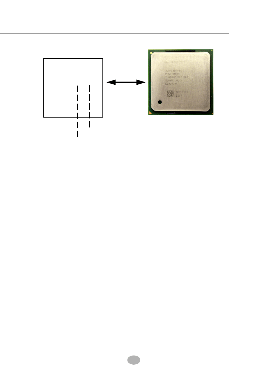
2-1 CPU Installation with Socket 478B
1) CPU Working Frequency
On the heatsink side of a Pentium 4 CPU, there printed a line of figures
to identify its specifications. The line consists of 4 parts:
1. CPU Working Frequency: this part depicts the working frequency of
the CPU. The Intel P4 processor with three differeent System Bus
mode provides a variety of speeds ranging from 2AGHz to 3.2GHz.
400MHz System Bus: 2.60, 2.50, 2.40, 2.20, 2A GHz
533MHz System Bus: 3.06, 2.80, 2.66, 2.53, 2.40, 2.26 GHz
800MHz System Bus: 3.20, 3, 2.80C, 2.60C, 2.40C GHz
2. CPU L2 Cache: this part depicts the L2 Cache size. For example,
512 stands for 512 KB L2 Cache; 256 stands for 256 KB L2 Cache
3. System Bus: this part depicts the System Bus (Front Side Bus) is
provided by CPU clock x 4. For example,
800MHz = 200MHz(CPU clock) x 4; 533MHz = 133MHz x 4
400MHz = 100MHz x 4
Note: System Bus vs CPU Clock
P4 CPU is a quad-pumped CPU. The system bus is provided by the
CPU clock x 4. Therefore, users can figure out the P4 CPU clock by the
System Bus divided by 4.
Intel
PENTIUM 4
2.80 GHz / 512 / 800
2) CPU L2 Cache
3) System Bus
Pentium 4 with Hyper Threading Technology :
(1) P4 processors at 2.40C, 2.60C, 2.80C, 3, 3.20GHz with an advanced
800MHz system bus
(2) P4 processor at 3.06Ghz with 533MHz system bus
2-1.1 To Identify a Pentium 4 CPU
(Hyper-threading &
Prescott CPU (Up to 3.2GHz)
18
SL-865Pro2-FGR
mPGA478B
In
te
l P
e
n
tiu
m
4
mPGA478B
Pin 1
2-1.2 CPU Installation with Socket 478B
This mainboard is built with CPU
Socket 478B ( 478-pin) supporting
the Intel Pentium 4 CPU:
• Follow the steps described in this
section to install the 478-pin Pen-
tium 4 CPU into the on board
Socket 478.
• After installation of Pentium 4 CPU,
you must also install the specific
Pentium 4 CPU fan designed in
tandem with this CPU. This CPU
Fan installation is described in next
section.
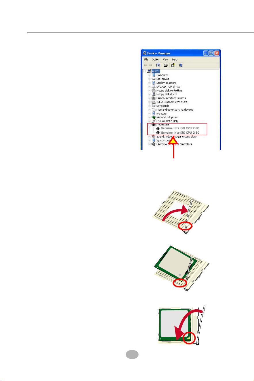
• This mainboard supports Hyper-
threading dual-in-one CPU, the
function of which can be enabled
by Windows XP. (See illustration
on the right.)
1. First pull sideways the lever of
Socket 478, and then turn it up
90
0
so as to raise the upper layer
of the socket from the lower
platform.
3. Make sure that all CPU pins have
completely entered the socket
and then lower down the lever
to lock up CPU to socket.
2. Configure Pin 1 of CPU to Pin 1
of the Socket, just as the way
shown in the diagram on the
right. Adjust the position of CPU
until you can feel all CPU pins
get into the socket with ease.
m
P
G
A
4
7
8
B
In
te
l P
e
n
tiu
m
4
Pin 1
GHz
GHz
( If Hyper-threading CPU is
installed successfully with O/S
Win XP, the O/S will enable the
dual-in-one CPU function.)
19
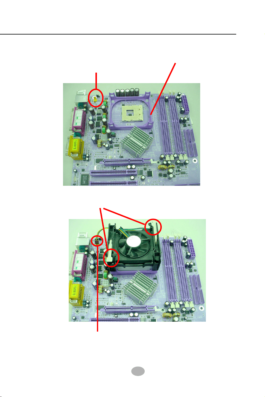
Chapter 2 Hardware Setup
Connect Fan Connector to CPU FAN connector
Pentium 4 Fanbase
2-2 Pentium 4 CPU Fan Installation:
CPU Fan Connector
Press down 2 Spring Locks to lock fan to fanbase
The above pictures are taken from sample mainboards as installation illustr-
ation. The layout in the pictures may be different from your mainboard.
20
SL-865Pro2-FGR
184-Pin DIMM Notch Key Definitions
DRAM Key Position Voltage Key Position
865PE
Intel
Intel 82865PE
BIOS
ALC655
AC'97
Li
Battery
PNT1
COM1
COM2
+12V Power
NJ1
HDD
IR
PWR
1
20
SPK RST
+
-
+
-
PWLED
LED
Fan3
Header USB3
AGP1 (8X/4X)
ICH5
Intel
IDE1
IDE2
IDE3
FD1
PCI1
PCI2
PCI3
PCI4
PCI5
DDR 400/333/266MHz
PW1¤
ATX Power
1
JKB1
JFSB2
JFSB1
PS/2 Mouse
(on top)
PS/2 Keyboard
¤
(underside)
SATA1
ATA1
SATA2
(m
id
d
le
)
1
L
i
n
e
i
n
(
o
n
t
o
p
)
L
i
n
e
O
u
t
(
u
n
d
e
r
s
id
e
)
M
i
c
1
CD_IN1
W83627HF
Winbond
USB1
DIMM1 DIMM2 DIMM3 DIMM4
1
USB2
USB4(2 ports)
RT3
IEEE1
RJ45
(on top)
VT6307
VIA
RTL
PDC20579
Promise
Fan2
Fan4
Fan1
Header
JBAT1
JAUD1
Audio1
14
1
1
1
PW2
JFSB3
1
1
1394A
(on top)
LGA775 CPU Socket
10
10
1
10
1
10
VT6122
VIA
¤
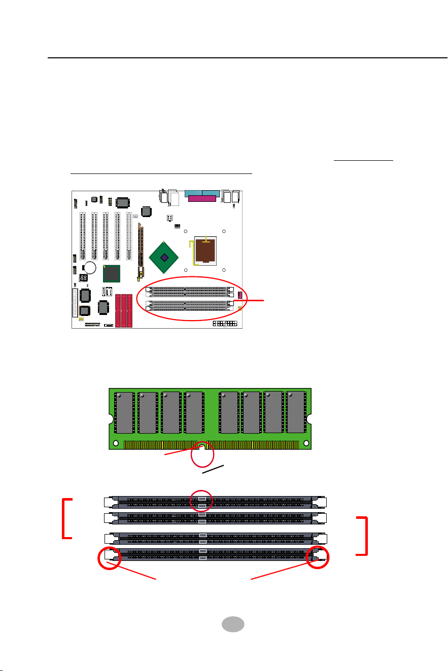
2-2 Memory Installation
DDR DIMM Slots
(184-pin)
2-2.1 To Install DDR SDRAM Module
• DDR DIMM slot has 184 pins and one notch. Insert a DDR SDRAM
vertically into the 184-pin slot with the notch-to-rib matching.
DDR Rib
(2.5V Voltage Key)DDR Notch
184-Pin DIMM Notch Key Definition
Module Latch
DIMM1
DIMM2
DIMM3
DIMM4
Bank B
Bank A
• This mainboard supports up to 4GB unbuffered Dual-channel DDR
400/333/266 SDRAM, with 4 DDR DIMM slots on board. Do not insert
other type of modules into these slots.

21
Chapter 2 Hardware Setup
2-2.3 To Remove a DIMM
Power off the system first, and then press down the holding latches on
both sides of slot to release the module from the DIMM slot.
• North Bridge i865PE supports Dual-channel SDRAM configuration.
• Dual Channel Memory Configuration is formed by couple of identical
DDR SDRAMs.
• Dual Channel memory configuration provides higher performance than
Single Channel configurations.
• Matched DIMMs need to have identical density, DRAM technology,
DRAM bus width, and equal number of memory banks.
• The dual memory controller can double the DDR memory bandwidth
up to 6.4GB/s with couple of DDR400, 5.4GB/s with couple of DDR333
and 4.2GB/s with couple of DDR266.
• To enable Dual-channel memory function,
users should insert totally
identical (size and frequency) DDR module pair into the bank-pair.
On this mainboard, DIMM1 + DIMM3 is a Dual channel bank-pair.
DIMM2 + DIMM4 is another. That means, dual-channel transmission
is only enabled in pair, not randomly by any two DIMMs.
2-2.2 Dual Channel Memory Module Installation
DIMM1+DIMM3 = Dual Channel Memory
or / and
DIMM2+DIMM4 = Dual Channel Memory
22
SL-865Pro2-FGR
865PE
Intel
Intel 82865PE
BIOS
RTL
ALC655
LPT1
COM1
COM2
mPGA478B
PW1
+12V Power
HDD
IR
PWR
1
20
SPK RST
+
-
+
-
PWLED
LED
F
a
n
1
1
USB3
RJ45
(on top)
AGP1 (8X/4X)
ICH5
Intel
IDE1
IDE2
IDE3
FDC1
PCI1
PCI2
PCI3
PCI4
PCI5
for Dual-channel DDR 400/333/266MHz
F
a
n
2
PW2
1
JKB1
1
JBAT1
1
JFSB2
JFSB1
PS/2 Mouse
(on top)
PS/2 Keyboard
(
m
id
d
le
)
JAUD1
1
L
i
n
e
i
n
(
o
n
t
o
p
)
L
i
n
e
O
u
t
(
u
n
d
e
r
s
id
e
)
M
i
c
1
CD_IN1
VT6307
VIA
W83627HF
Winbond
USB4
DIMM1 DIMM2
DIMM3 DIMM4
SATA1
SATA2
PDC20378
Promise
1
USB2
USB1(2 ports)
1
IEEE1
10
F
a
n
3
IEEE
1394
VIA
VT6122
Li
Battery
JFSB3
ATA1
AUDIO1
Main Power
F
a
n
4
(2 ports)
RT3
82801EB
22
1
2
2
2
10
(underside)
LED1
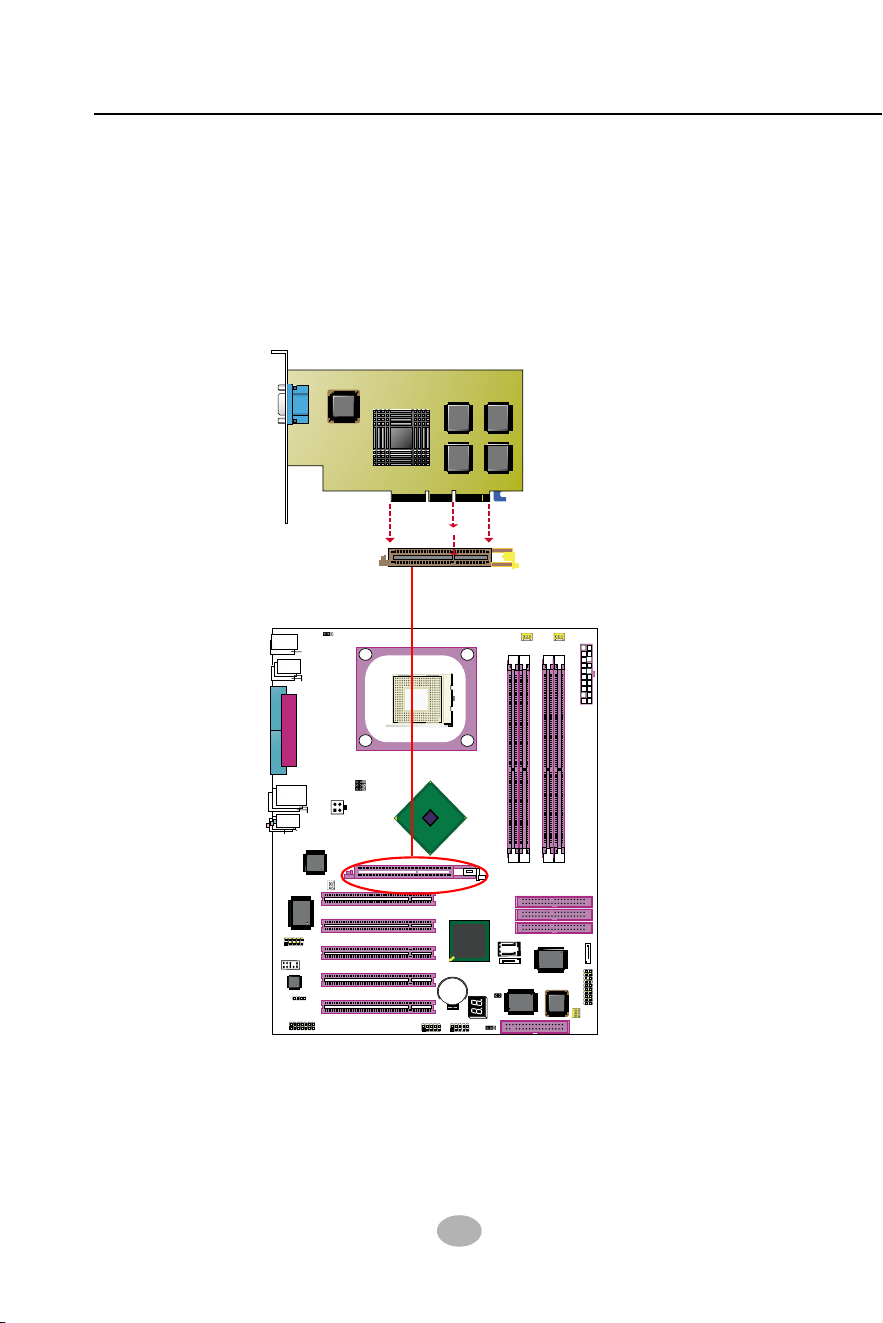
2-3 AGP 8X/4X Slot Installation
AGP Accelerator
notch
AGP 8X/4X Slot
The AGP slot on board supports 1.5V AGP 8X/4X card only. A Rib is
specifically added to the 8X/4X slot so as to match the AGP 8X/4X card.
To insert a 3.3V AGP 2X card into the AGP 4X slot will damage the
system chip and burn the 1.5V circuitry.
An AGP 8X card will support a data transfer rate up to 2GB/sec, while
an AGP 4X card will provide 1GB/sec transfer rate.
23
Chapter 2 Hardware Setup
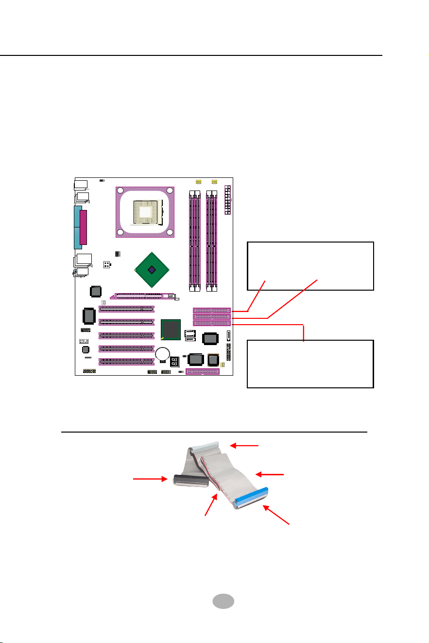
2-4 IDE Connectors Installation
To install IDE Connector, you may connect the blue connector of IDE
cable to the primary (IDE1) or secondary (IDE2) connector on board,
and then connect the gray connector to your slave device and the black
connector to your master device. If you install two hard disks, you must
configure the second drive to Slave mode by setting its jumpers correctly.
Please refer to your hard disk documentation for the jumper settings.
Orient the red line on the IDE
Flat Cable to Pin1.
Pin 1 (to Red Line)
ATA 100 IDE Connector
IDE1
IDE2
Gray connector
Blue connector
Black connector
Red line
(To Mainboard)
(To Slave device)
(To Master Device)
IDE Flat Cable
80-conductor
cable
Supported by Promise
PDC20378 for 2 Parallel ATA
RAID IDE Hard Disks Setup.
PATA 133 Connector
IDE3
865PE
Intel
Intel 82865PE
BIOS
RTL
ALC655
LPT1
COM1
COM2
mPGA478B
PW1
+12V Power
HDD
IR
PWR
1
20
SPK RST
+
-
+
-
PWLED
LED
F
a
n
1
1
USB3
RJ45
(on top)
AGP1 (8X/4X)
ICH5
Intel
IDE1
IDE2
IDE3
FDC1
PCI1
PCI2
PCI3
PCI4
PCI5
for Dual-channel DDR 400/333/266MHz
F
a
n
2
PW2
1
JKB1
1
JBAT1
1
JFSB2
JFSB1
PS/2 Mouse
(on top)
PS/2 Keyboard
(
m
id
d
le
)
JAUD1
1
L
i
n
e
i
n
(
o
n
t
o
p
)
L
i
n
e
O
u
t
(
u
n
d
e
r
s
id
e
)
M
i
c
1
CD_IN1
VT6307
VIA
W83627HF
Winbond
USB4
DIMM1 DIMM2
DIMM3 DIMM4
SATA1
SATA2
PDC20378
Promise
1
USB2
USB1(2 ports)
1
IEEE1
10
F
a
n
3
IEEE
1394
VIA
VT6122
Li
Battery
JFSB3
ATA1
AUDIO1
Main Power
F
a
n
4
(2 ports)
RT3
82801EB
22
1
2
2
2
10
(underside)
LED1
24
SL-865Pro2-FGR
865PE
Intel
Intel 82865PE
BIOS
RTL
ALC655
LPT1
COM1
COM2
mPGA478B
PW1
+12V Power
HDD
IR
PWR
1
20
SPK RST
+
-
+
-
PWLED
LED
F
a
n
1
1
USB3
RJ45
(on top)
AGP1 (8X/4X)
ICH5
Intel
IDE1
IDE2
IDE3
FDC1
PCI1
PCI2
PCI3
PCI4
PCI5
for Dual-channel DDR 400/333/266MHz
F
a
n
2
PW2
1
JKB1
1
JBAT1
1
JFSB2
JFSB1
PS/2 Mouse
(on top)
PS/2 Keyboard
(
m
id
d
le
)
JAUD1
1
L
i
n
e
i
n
(
o
n
t
o
p
)
L
i
n
e
O
u
t
(
u
n
d
e
r
s
id
e
)
M
i
c
1
CD_IN1
VT6307
VIA
W83627HF
Winbond
USB4
DIMM1 DIMM2
DIMM3 DIMM4
SATA1
SATA2
PDC20378
Promise
1
USB2
USB1(2 ports)
1
IEEE1
10
F
a
n
3
IEEE
1394
VIA
VT6122
Li
Battery
JFSB3
ATA1
AUDIO1
Main Power
F
a
n
4
(2 ports)
RT3
82801EB
22
1
2
2
2
10
(underside)
LED1
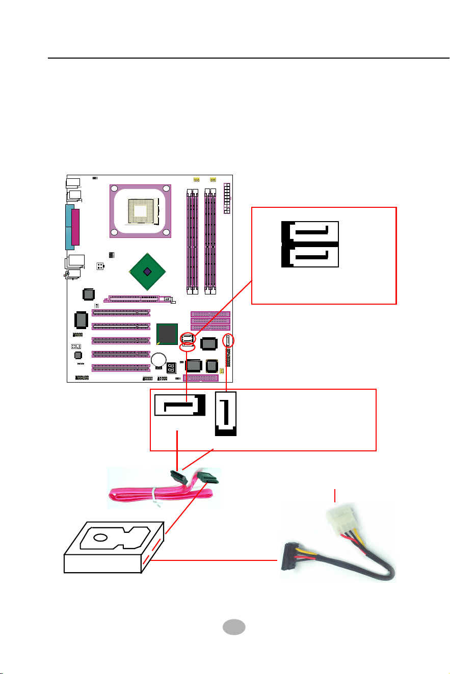
2-5 Serial ATA Connectors Installation
The Serial ATA is designed to improve the Parallel ATA with the capabil-
ity of Hot Plug and offer a data bandwidth of 150Mbytes/second. It also
reduce voltage and pin count and can be implemented with thin cables
which improve the inner ventilaton of PC cases.
2 Serial ATA connectors are built on board, supported by the SATA Con-
troller for SATA Hard Disk Drives.
Serial ATA Hard Disk
Serial ATA Cable
Serial ATA Power Cable
To Power Supply
SATA Power Connectors
ATA1
(2 ports)
(optional)
Serial ATA Connectors
SATA Connectors supported
by PDC20378 for 2 SATA
RAID Hard Disks Setup
SATA2
SATA1
SATA Connectors supported
by ICH5 for 2 SATA Hard
Disks setup (Not RAID)
25
Chapter 2 Hardware Setup
865PE
Intel
Intel 82865PE
BIOS
RTL
ALC655
LPT1
COM1
COM2
mPGA478B
PW1
+12V Power
HDD
IR
PWR
1
20
SPK RST
+
-
+
-
PWLED
LED
F
a
n
1
1
USB3
RJ45
(on top)
AGP1 (8X/4X)
ICH5
Intel
IDE1
IDE2
IDE3
FDC1
PCI1
PCI2
PCI3
PCI4
PCI5
for Dual-channel DDR 400/333/266MHz
F
a
n
2
PW2
1
JKB1
1
JBAT1
1
JFSB2
JFSB1
PS/2 Mouse
(on top)
PS/2 Keyboard
(
m
id
d
le
)
JAUD1
1
L
i
n
e
i
n
(
o
n
t
o
p
)
L
i
n
e
O
u
t
(
u
n
d
e
r
s
id
e
)
M
i
c
1
CD_IN1
VT6307
VIA
W83627HF
Winbond
USB4
DIMM1 DIMM2
DIMM3 DIMM4
SATA1
SATA2
PDC20378
Promise
1
USB2
USB1(2 ports)
1
IEEE1
10
F
a
n
3
IEEE
1394
VIA
VT6122
Li
Battery
JFSB3
ATA1
AUDIO1
Main Power
F
a
n
4
(2 ports)
RT3
82801EB
22
1
2
2
2
10
(underside)
LED1
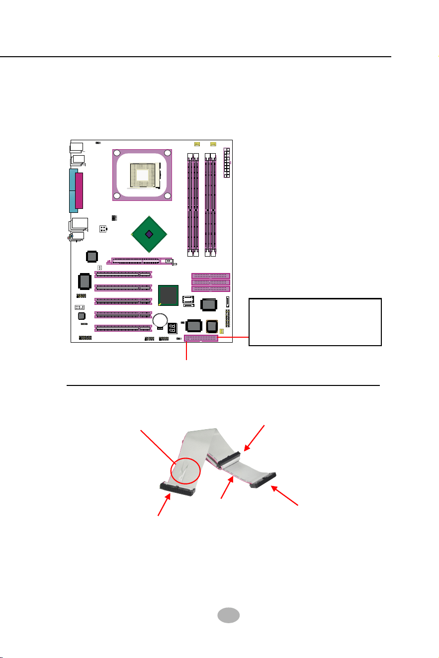
To install FDC, you should connect the end of FDC cable with single
connector to the board, and connect the other end with two connectors
to the floppy drives.
2-6 Floppy Drive Connector Installation
Floppy Drive Connector:
Pin 1 (to Red Line)
FDD Cable
To 1st Floppy Drive
To Mainboard
To 2nd Floppy Drive
Red line
Signal Swap End
Orient the red line of the
Floppy Flat Cable to Pin1.
26
SL-865Pro2-FGR
865PE
Intel
Intel 82865PE
BIOS
RTL
ALC655
LPT1
COM1
COM2
mPGA478B
PW1
+12V Power
HDD
IR
PWR
1
20
SPK RST
+
-
+
-
PWLED
LED
F
a
n
1
1
USB3
RJ45
(on top)
AGP1 (8X/4X)
ICH5
Intel
IDE1
IDE2
IDE3
FDC1
PCI1
PCI2
PCI3
PCI4
PCI5
for Dual-channel DDR 400/333/266MHz
F
a
n
2
PW2
1
JKB1
1
JBAT1
1
JFSB2
JFSB1
PS/2 Mouse
(on top)
PS/2 Keyboard
(
m
id
d
le
)
JAUD1
1
L
i
n
e
i
n
(
o
n
t
o
p
)
L
i
n
e
O
u
t
(
u
n
d
e
r
s
id
e
)
M
i
c
1
CD_IN1
VT6307
VIA
W83627HF
Winbond
USB4
DIMM1 DIMM2
DIMM3 DIMM4
SATA1
SATA2
PDC20378
Promise
1
USB2
USB1(2 ports)
1
IEEE1
10
F
a
n
3
IEEE
1394
VIA
VT6122
Li
Battery
JFSB3
ATA1
AUDIO1
Main Power
F
a
n
4
(2 ports)
RT3
82801EB
22
1
2
2
2
10
(underside)
LED1
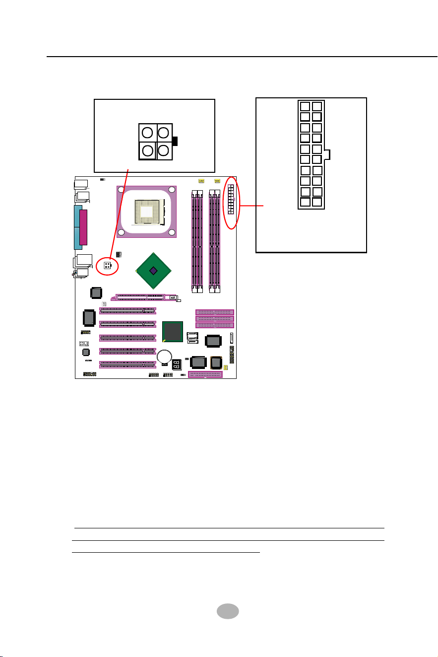
ATX V2.03 Power Supply is strongly recommended for mainboard run-
ning with 2GHz or higher CPU.
To set up Power Supply on this mainboard:
1. Connect the on-board Main Power Connector (20-pin) to the Main
Power Connector (20-pin) of an ATX Power Supply which can be of
the latest version 2.03 model, and then connect the square-shaped
+12V Power Connector on board to the square-shaped +12V Power
Connector of the Power Supply.
Warning: Both the Main Power Connector and the +12V Power
Connector should be connected to Power Supply; otherwise, the
system may either not start or damaged.
2. This ATX Power Supply should be able to provide at least 720mA/
+5V standby power for Wake On Lan function.
2-7 ATX V2.03 Power Supply Installation
+12V
5SB
PWR OK
GND
GND
GND
GND
GND
GND
+5V
+5V
-5V
+5V
+5V
+3.3V
+3.3V +3.3V
PS ON#
Pin1 Pin11
-12V
GND
Main Power Connector
(20-pin)
+12V Power Connector
GND
+12V
3
GND
24
1
+12V
27
Chapter 2 Hardware Setup
865PE
Intel
Intel 82865PE
BIOS
RTL
ALC655
LPT1
COM1
COM2
mPGA478B
PW1
+12V Power
HDD
IR
PWR
1
20
SPK RST
+
-
+
-
PWLED
LED
F
an
1
1
USB3
RJ45
(on top)
AGP1 (8X/4X)
ICH5
Intel
IDE1
IDE2
IDE3
FDC1
PCI1
PCI2
PCI3
PCI4
PCI5
for Dual-channel DDR 400/333/266MHz
Fan2
PW2
1
JKB1
1
JBAT1
1
JFSB2
JFSB1
PS/2 Mouse
(on top)
PS/2 Keyboard
(
m
id
d
le
)
JAUD1
1
L
i
n
e
i
n
(on top)
L
i
n
e
O
u
t
(
u
n
d
e
r
s
id
e
)
M
i
c
1
CD_IN1
VT6307
VIA
W83627HF
Winbond
USB4
DIMM1 DIMM2
DIMM3 DIMM4
SATA1
SATA2
PDC20378
Promise
1
USB2
USB1(2 ports)
1
IEEE1
10
F
an
3
IEEE
1394
VIA
VT6122
Li
Battery
JFSB3
ATA1
AUDIO1
Main Power
Fan
4
(2 ports)
RT3
82801EB
22
1
2
2
2
10
(underside)
LED1
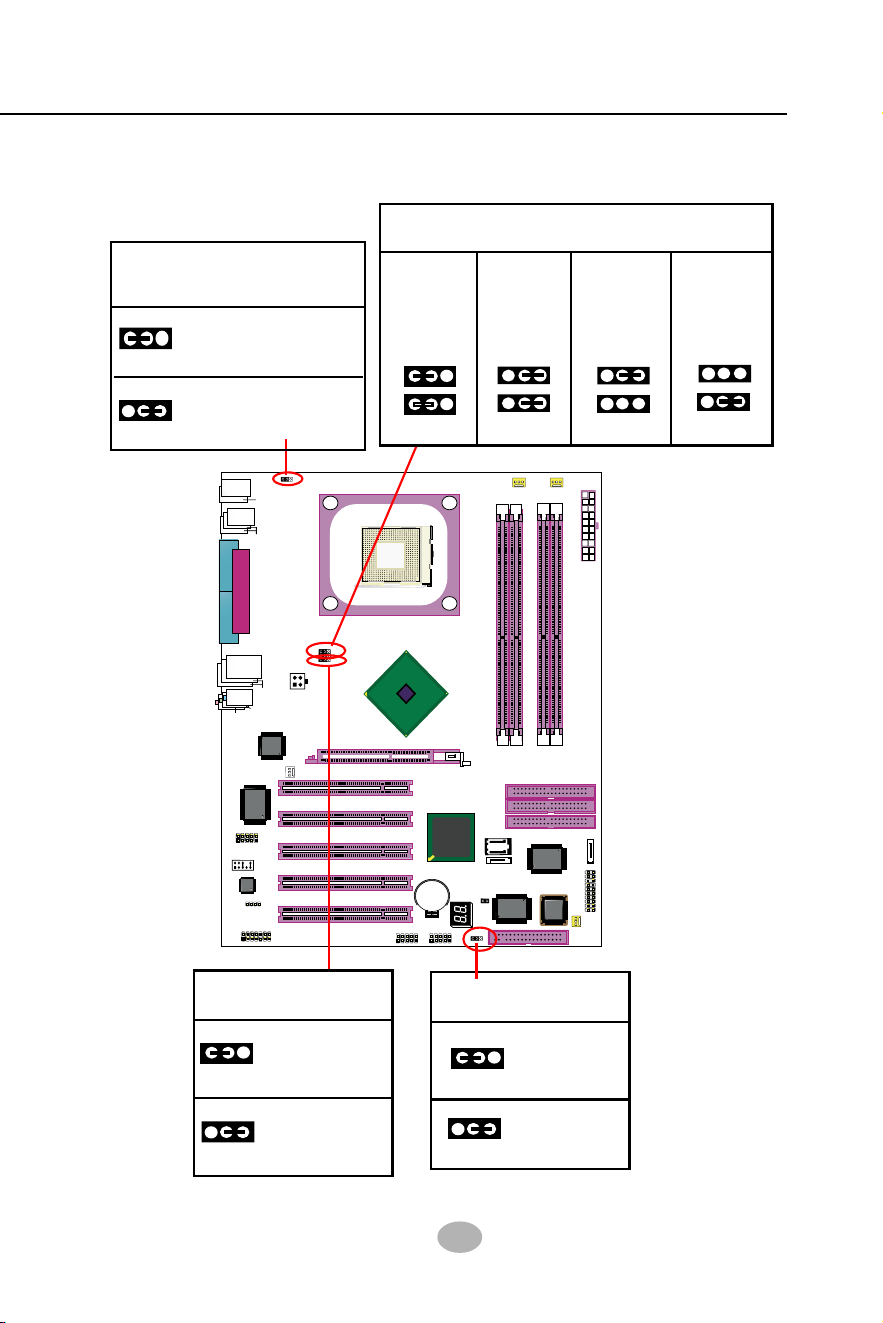
2-8 Jumper Settings
The following diagrams show the locations and settings of jumper blocks
on the mainboard.
Keyboard / Mouse
Wake Up
1
1
JKB1:
1-2 closed (default)
Disabled
2-3 closed
Enabled
Memory Turbo Mode
1-2 closed
(default)
1
1
2-3 closed
JFSB3
Turbo Mode Disabled
Turbo Mode Enabled
(default)
JFSB1&JFSB2:
CPU Frequency Select
CPU
Auto-
Detection
133MHz
200MHz
(FSB800)
JFSB1
JFSB2
1
1
1
1
JFSB2
JFSB1
1
1
JFSB2
JFSB1
(FSB533)
Clear CMOS
1-2 closed
(default)
To hold data
2-3 closed
To clear CMOS
JBAT1
1
1
100MHz
1
1
JFSB2
JFSB1
(FSB400)
28
SL-865Pro2-FGR
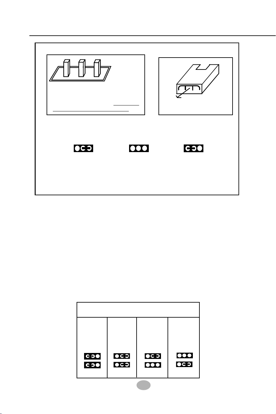
1 13313
Jumper with
Pin 2-3 closed
Jumper with
all pins opened
Jumper with
Pin 1-2 closed
• A Jumper is usually but not necessarily given a “JpX” legend.
Jp X
• Do not remove any jumper cap when power is on. Always
make sure the power is off before changing any jumper settings.
Otherwise, the mainboard will be damaged.
How to tackle the Jumpers:
• In the Jumper setting diagram, the jumper pins covered with
black marks stand for closed pins with jumper cap.
If a pin-header (of 2 or more pins) is
designed in such a way that its pins
can be closed or linked together to
set up a specific function,
this header
is called a jumper in this manual.
A 3-pin Jumper
The conductor inside the cap
links two header-pins together.
123
A 2-pin
Jumper
Cap
JFSB1 and JFSB2 are designed on board for CPU frequency select.
2-8.1 JFSB1 & JFSB2: CPU Frequency Select
2. Setting JFSB1 all open and JFSB2 2-3 closed is for 133 MHz CPU.
3. Setting JFSB1 2-3 closed and JFSB2 opened is for 200 MHz CPU.
4. If 200MHz is an overclock for your CPU, it may or may not boot your
system. If an overclok fails to boot system, you should restore the
default setting and then clear CMOS to reboot your system. (See
Clear CMOS in next paragraph.)
1. Setting JFSB1 and JFSB2 to 1-2 closed will allow CPU on board to
Auto Detect its own frequency.
2. Setting FSB1 and FSB2 to 2-3 closed is for 100MHz CPU or 400MHz
FSB to boot system..
(default)
JFSB1&JFSB2:
CPU Frequency Select
CPU
Auto-
Detection
133MHz
200MHz
(FSB800)
JFSB1
JFSB2
1
1
1
1
JFSB2
JFSB1
1
1
JFSB2
JFSB1
(FSB533)
100MHz
1
1
JFSB2
JFSB1
(FSB400)

29
Chapter 2 Hardware Setup
When you have problem with rebooting your system, you can clear
CMOS data and restore it to default value. To clear CMOS with Jumper
JBAT1, please follow the steps below:
1. Power off system.
2. Set JBAT1 to Pin 2-3 closed.
3. After 2 or 3 seconds, restore the JBAT1 setting to Pin1-2 closed.
4. CMOS data are restored to default now. Remember never clear
CMOS when system power is on.
2-8.2 JBAT1: Clear CMOS
Further Notes on CPU Overclocking:
1. If you have successfully booted system, with or without CPU
overclock, you still can try another CPU overclock in BIOS Setup.
Please enter BIOS Setup, choose “Voltage Control” of Advanced BIOS
Features, and configure the “CPU Clock” item to raise your CPU clock.
2. CPU overclocking should take all components on board into account.
If you fail in BIOS overclocking, you will not be able to restart system.
In such case, Power off system and clear CMOS by JBAT1 and then
restart your system. And remember to reconfigure whatever should
be reconfigured.
3. If your system is already fixed in a cabinet or case, you may not like
to take the trouble to clear CMOS. Then power on your system with
the power button on the PC case and simultaneously press down the
“Insert” key on the keyboard until you see the initial bootup screen
appear. And remember you should also enter CMOS BIOS Setup
instantly and choose “Load Optimized Defaults” to restore default
BIOS .
Clear CMOS
1-2 closed
(default)
To hold data
2-3 closed
To clear CMOS
JBAT1
1
1
30
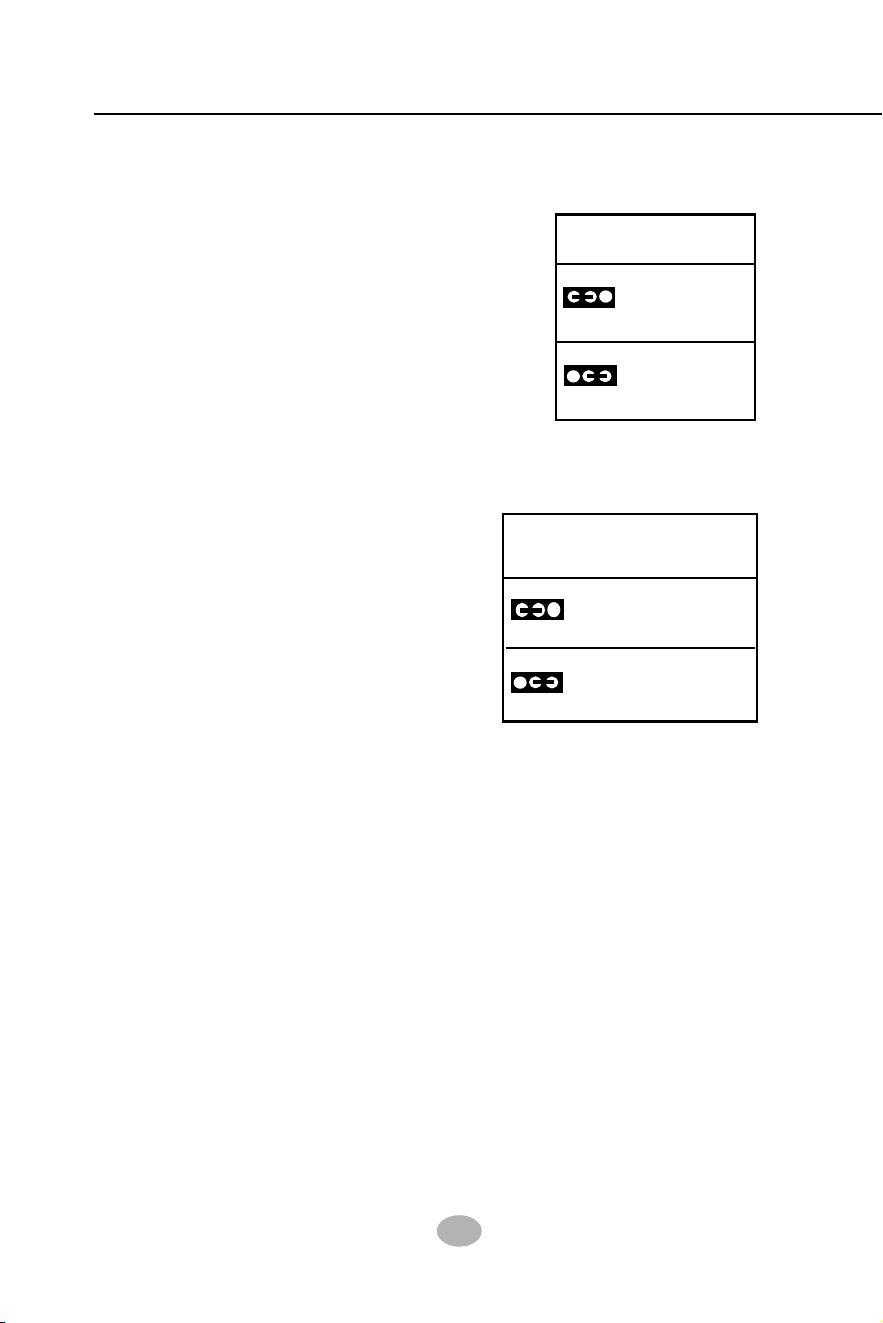
SL-865Pro2-FGR
2-8.4 JKB1: Keyboard / Mouse Wake Up
JKB1 is designed on board as a jumper
to enable/disable the PS/2 keyboard/
mouse Wake Up from suspend mode.
USB keyboard/mouse Wake Up func-
tion is an optional function on this
mainboard.
Keyboard / Mouse
Wake Up
1
1
JKB1:
1-2 closed (default)
Disabled
2-3 closed
Enabled
2-8.3 (Optional) JFSB3: Memory Turbo Mode
Memory Turbo Mode
1-2 closed
(default)
1
1
2-3 closed
JFSB3
Turbo Mode Disabled
Turbo Mode Enabled
JFSB3 is designed on board for improving
Memory performance. If you want to obtain
better system performance, you can set
JFSB3 2-3 closed to enable the Memory
Turbo Mode.
(Optional)
31
Chapter 2 Hardware Setup
865PE
Intel
Intel 82865PE
BIOS
RTL
ALC655
LPT1
COM1
COM2
mPGA478B
PW1
+12V Power
HDD
IR
PWR
1
20
SPK RST
+
-
+
-
PWLED
LED
F
a
n
1
1
USB3
RJ45
(on top)
AGP1 (8X/4X)
ICH5
Intel
IDE1
IDE2
IDE3
FDC1
PCI1
PCI2
PCI3
PCI4
PCI5
for Dual-channel DDR 400/333/266MHz
F
a
n
2
PW2
1
JKB1
1
JBAT1
1
JFSB2
JFSB1
PS/2 Mouse
(on top)
PS/2 Keyboard
(
m
id
d
le
)
JAUD1
1
L
i
n
e
i
n
(
o
n
t
o
p
)
L
i
n
e
O
u
t
(
u
n
d
e
r
s
id
e
)
M
i
c
1
CD_IN1
VT6307
VIA
W83627HF
Winbond
USB4
DIMM1 DIMM2
DIMM3 DIMM4
SATA1
SATA2
PDC20378
Promise
1
USB2
USB1(2 ports)
1
IEEE1
10
F
a
n
3
IEEE
1394
VIA
VT6122
Li
Battery
JFSB3
ATA1
AUDIO1
Main Power
F
a
n
4
(2 ports)
RT3
82801EB
22
1
2
2
2
10
(underside)
LED1
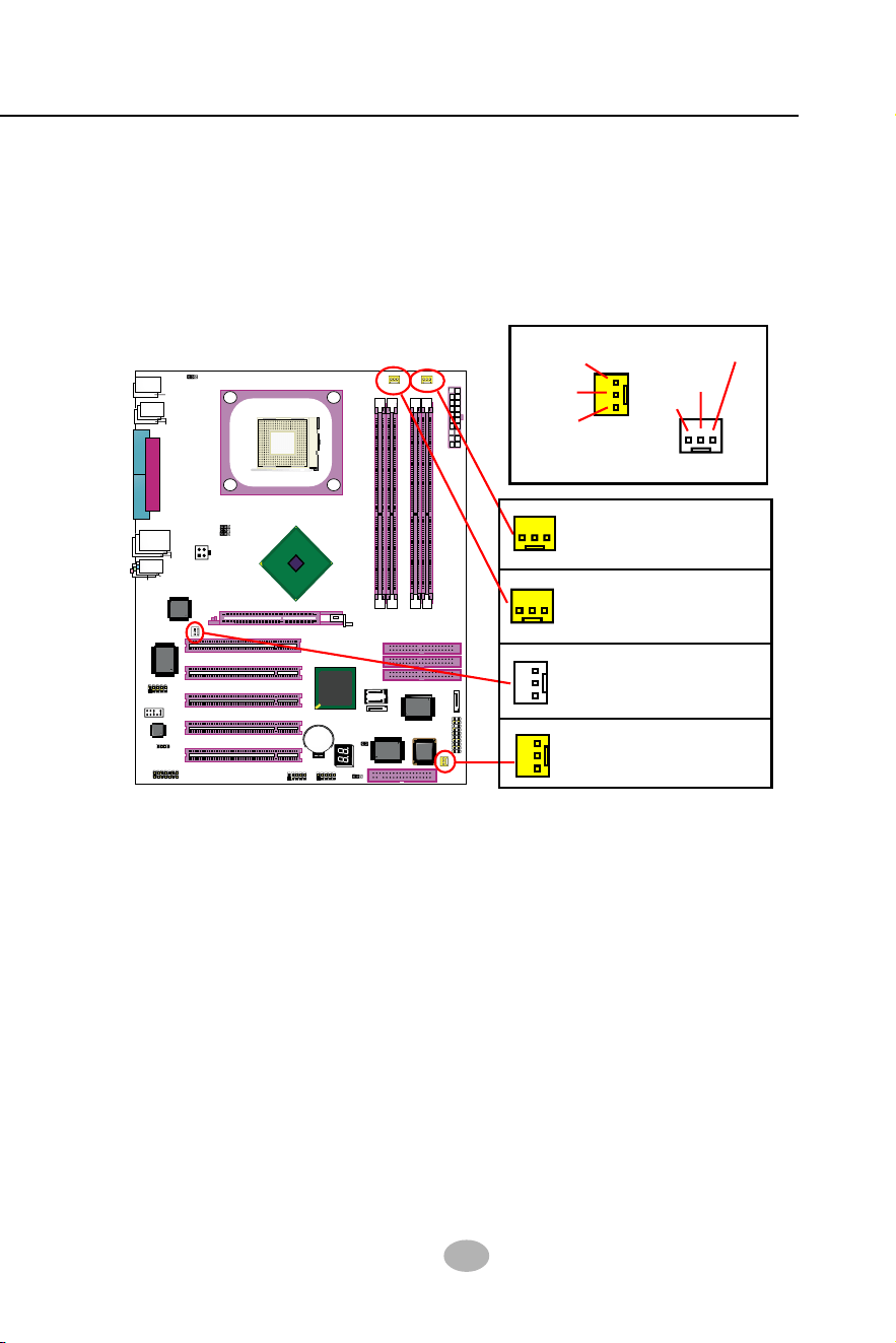
This section lists out all connectors configurations for users’ reference.
FAN1 is a sensor Fan connector supporting speed detection. FAN1 is
for CPU cooling fan.
FAN2 is a sensor Fan connector supporting Fan speed detection
function. Fan2 is for chassis cooling Fan.
FAN3 is a 3-pin sensor Fan connector, supporting speed detection.
You can connect CPU/System fan to Fan3.
Fan4 is a non-sensor Fan connector
3-pin Fan Connector
Fan3, yellow, sensor
Fan Connector
Fan2, yellow, sensor
Sensor Conn.
No Sensor
Void
+12V
GND
Sensor
+12V
GND
Fan Connector
Fan4, white, no sensor
2-9 Other Connectors Configuration
2-9.1 On Board Fan Connectors
CPU Fan Connector
Fan1, sensor, Control
32
SL-865Pro2-FGR
865PE
Intel
Intel 82865PE
BIOS
RTL
ALC655
LPT1
COM1
COM2
mPGA478B
PW1
+12V Power
HDD
IR
PWR
1
20
SPK RST
+
-
+
-
PWLED
LED
Fan
1
1
USB3
RJ45
(on top)
AGP1 (8X/4X)
ICH5
Intel
IDE1
IDE2
IDE3
FDC1
PCI1
PCI2
PCI3
PCI4
PCI5
for Dual-channel DDR 400/333/266MHz
Fan2
PW2
1
JKB1
1
JBAT1
1
JFSB2
JFSB1
PS/2 Mouse
(on top)
PS/2 Keyboard
(
m
id
d
le
)
JAUD1
1
L
i
n
e
i
n
(
o
n
t
o
p
)
L
i
n
e
O
u
t
(
u
n
d
e
r
s
id
e
)
M
i
c
1
CD_IN1
VT6307
VIA
W83627HF
Winbond
USB4
DIMM1 DIMM2
DIMM3 DIMM4
SATA1
SATA2
PDC20378
Promise
1
USB2
USB1(2 ports)
1
IEEE1
10
Fan3
IEEE
1394
VIA
VT6122
Li
Battery
JFSB3
ATA1
AUDIO1
Main Power
Fan
4
(2 ports)
RT3
82801EB
22
1
2
2
2
10
(underside)
LED1
USB Header
1
10
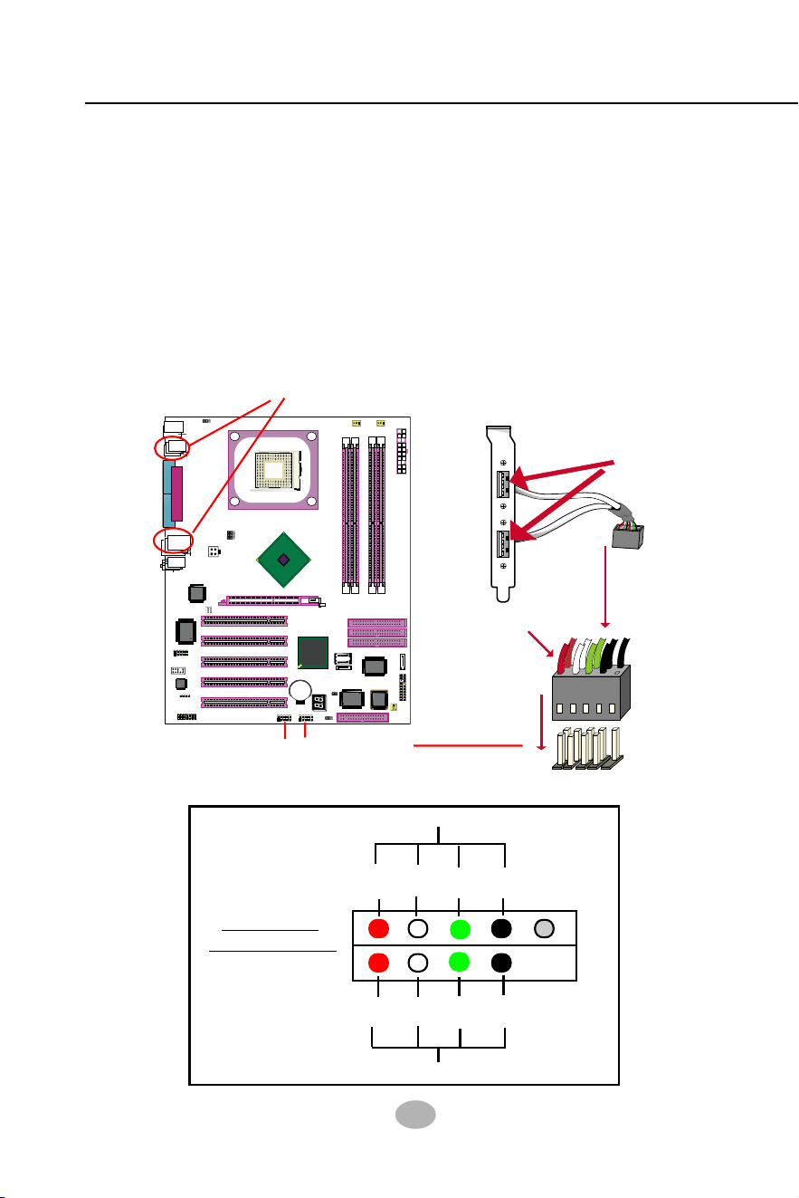
First USB Port Wiring for Front USB
Second USB Port Wiring for Front USB
+5V
Red White
black
+5V
Red
Green
Green
White
black
GND
GND
Pin Assignment
D1-
D1+
D2-
D2+
2-9.2 USB Ports and USB Pin-headers
This mainboard provides four USB ports on board supporting various
USB devices. In addition, two USB pin-headers are added on board to
provide expansion of four more optional USB ports by using two addi-
tional USB cables. Users can order the optional USB cables from your
mainboard dealer or vendor.
When plugging the USB cable to USB Header, users must make sure
the red wire is connected to Pin 1.
All 8 USB ports are compliant with 1.1 / 2.0 USB Bus. USB 2.0 supports
Windows 2000 and up (no support for Windows 9X/ME). Please see
Chapter 3 for USB2.0 Installation.
1
USB Cable (Optional)
Red wire
USB Port
1
10
10
USB connectors
Header USB3/2
for 4 USB ports
33
Chapter 2 Hardware Setup
865PE
Intel
Intel 82865PE
BIOS
RTL
ALC655
LPT1
COM1
COM2
mPGA478B
PW1
+12V Power
HDD
IR
PWR
1
20
SPK RST
+
-
+
-
PWLED
LED
F
a
n
1
1
USB3
RJ45
(on top)
AGP1 (8X/4X)
ICH5
Intel
IDE1
IDE2
IDE3
FDC1
PCI1
PCI2
PCI3
PCI4
PCI5
for Dual-channel DDR 400/333/266MHz
F
a
n
2
PW2
1
JKB1
1
JBAT1
1
JFSB2
JFSB1
PS/2 Mouse
(on top)
PS/2 Keyboard
(
m
id
d
le
)
JAUD1
1
L
i
n
e
i
n
(
o
n
t
o
p
)
L
i
n
e
O
u
t
(
u
n
d
e
r
s
id
e
)
M
i
c
1
CD_IN1
VT6307
VIA
W83627HF
Winbond
USB4
DIMM1 DIMM2
DIMM3 DIMM4
SATA1
SATA2
PDC20378
Promise
1
USB2
USB1(2 ports)
1
IEEE1
10
F
a
n
3
IEEE
1394
VIA
VT6122
Li
Battery
JFSB3
ATA1
AUDIO1
Main Power
F
a
n
4
(2 ports)
RT3
82801EB
22
1
2
2
2
10
(underside)
LED1
2-9.4 CD-ROM Audio Connectors
CD_IN1 is an audio connector connecting CD-ROM audio to mainboard.
CD-ROM Audio Pin Assignment
1
CD_IN1
Pin 1 Pin 2 Pin 3 Pin 4
Left
Channel
GND GND
Right
Channel
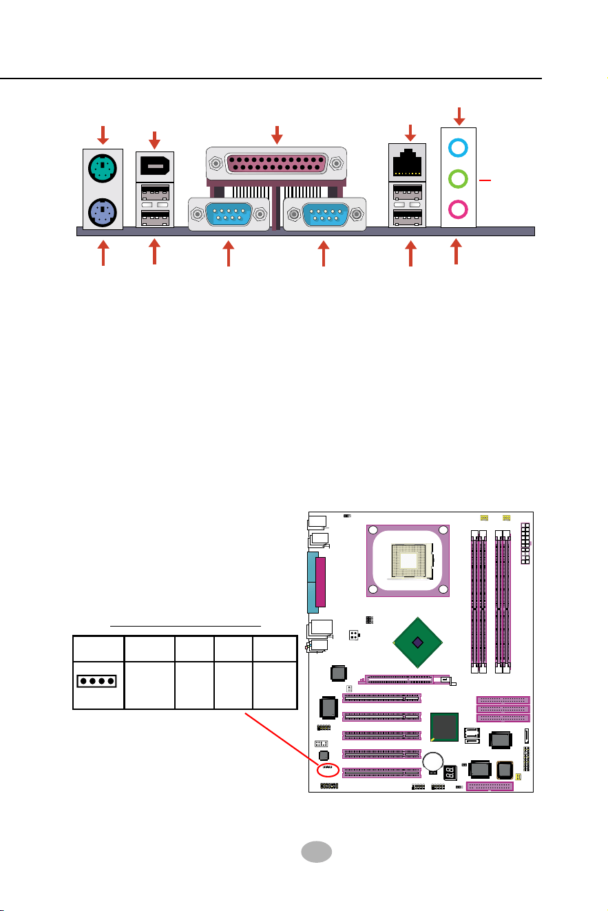
2-9.3 Chassis Panel Connectors
A : PS/2 Mouse
B : 1394A connector
C : LPT1 Port
D : RJ45
E : Line in/
Rear Speaker Out
F : PS/2 Keyboard
G : USB 4 (2 ports)
H : COM1 Connector
I : COM2 Connector
J : USB 1 (2 ports)
K : Microphone Input /
Center Subwoofer Out
L : Line Out /
Front Speaker Out
A
F
G
HIJ
K
C
D
E
B
L
34
SL-865Pro2-FGR
865PE
Intel
Intel 82865PE
BIOS
RTL
ALC655
LPT1
COM1
COM2
mPGA478B
PW1
+12V Power
HDD
IR
PWR
1
20
SPK RST
+
-
+
-
PWLED
LED
F
a
n
1
1
USB3
RJ45
(on top)
AGP1 (8X/4X)
ICH5
Intel
IDE1
IDE2
IDE3
FDC1
PCI1
PCI2
PCI3
PCI4
PCI5
for Dual-channel DDR 400/333/266MHz
F
a
n
2
PW2
1
JKB1
1
JBAT1
1
JFSB2
JFSB1
PS/2 Mouse
(on top)
PS/2 Keyboard
(
m
id
d
le
)
JAUD1
1
L
i
n
e
i
n
(
o
n
t
o
p
)
L
i
n
e
O
u
t
(
u
n
d
e
r
s
id
e
)
M
i
c
1
CD_IN1
VT6307
VIA
W83627HF
Winbond
USB4
DIMM1 DIMM2
DIMM3 DIMM4
SATA1
SATA2
PDC20378
Promise
1
USB2
USB1(2 ports)
1
IEEE1
10
F
a
n
3
IEEE
1394
VIA
VT6122
Li
Battery
JFSB3
ATA1
AUDIO1
Main Power
F
a
n
4
(2 ports)
RT3
82801EB
22
1
2
2
2
10
(underside)
LED1
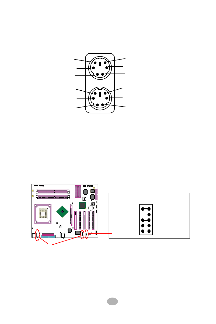
2-9.5 PS/2 Mouse And PS/2 Keyboard
6 Void
4 VCC
2 Void
1 Mouse Data
3 GND
5 Mouse Clock
6 Void
4 VCC
2 Void
5 Keyboard Clock
3 GND
1 Keyboard Data
(PS/2 Mouse: On top of keyboard connector, green)
(PS/2 Keyboard Connector: Underside, purple)
2-9.6 External Audio Connector
JAUD1: External Audio Connector
Pin 1 Mic In
Pin 3 Mic VREF
Pin 5 FPOUT R
Pin 7 (Key)
Pin 9 FPOUT L
Pin 2 Aud GND
Pin 4 Aud Vcc
Pin 6 RET R
Pin 10 RET L
This Mainboard is designed with an External Audio connector “JAUD1”
which provides connection to your chassis.
1. When JAUD1 is set to 5-6 closed and 9-10 closed, this default setting
disables this connector and leaves the Back Panel Audio enabled.
2. To use this Front Panel Audio Connector, please open all pins of
JAUD1 and connect it to your chassis.
2-9.7 1394A Connector
• PCI-bus based open host controller, compliant with IEEE 1394a-2000
standard for high performance serial bus
• Supporting 400/200/100 Mbits transfer rate.
1394A connectors
• 2 IEEE 1394A ports supported by IEEE1394A controller VT6307
35
Chapter 2 Hardware Setup
865PE
Intel
Intel 82865PE
BIOS
RTL
ALC655
LPT1
COM1
COM2
mPGA478B
PW1
+12V Power
HDD
IR
PWR
1
20
SPK RST
+
-
+
-
PWLED
LED
Fan1
1
USB3
RJ45
(on top)
AGP1 (8X/4X)
ICH5
Intel
IDE1
IDE2
IDE3
FDC1
PCI1
PCI2
PCI3
PCI4
PCI5
for Dual-channel DDR 400/333/266MHz
Fan2
PW2
1
JKB1
1
JBAT1
1
JFSB2
JFSB1
PS/2 Mouse
(on top)
PS/2 Keyboard
(
m
id
d
le
)
JAUD1
1
L
i
n
e
i
n
(
o
n
t
o
p
)
L
i
n
e
O
u
t
(
u
n
d
e
r
s
id
e
)
M
i
c
1
CD_IN1
VT6307
VIA
W83627HF
Winbond
USB4
DIMM1 DIMM2
DIMM3 DIMM4
SATA1
SATA2
PDC20378
Promise
1
USB2
USB1(2 ports)
1
IEEE1
10
Fan3
IEEE
1394
VIA
VT6122
Li
Battery
JFSB3
ATA1
AUDIO1
Main Power
Fan4
(2 ports)
RT3
82801EB
22
1
2
2
2
10
(underside)
LED1
865PE
Intel
Intel 82865PE
BIOS
RTL
ALC655
LPT1
COM1
COM2
mPGA478B
PW1
+12V Power
HDD
IR
PWR
1
20
SPK RST
+
-
+
-
PWLED
LED
F
a
n
1
1
USB3
RJ45
(on top)
AGP1 (8X/4X)
ICH5
Intel
IDE1
IDE2
IDE3
FDC1
PCI1
PCI2
PCI3
PCI4
PCI5
for Dual-channel DDR 400/333/266MHz
F
a
n
2
PW2
1
JKB1
1
JBAT1
1
JFSB2
JFSB1
PS/2 Mouse
(on top)
PS/2 Keyboard
(
m
id
d
le
)
JAUD1
1
L
i
n
e
i
n
(
o
n
t
o
p
)
L
i
n
e
O
u
t
(
u
n
d
e
r
s
id
e
)
M
i
c
1
CD_IN1
VT6307
VIA
W83627HF
Winbond
USB4
DIMM1 DIMM2
DIMM3 DIMM4
SATA1
SATA2
PDC20378
Promise
1
USB2
USB1(2 ports)
1
IEEE1
10
F
a
n
3
IEEE
1394
VIA
VT6122
Li
Battery
JFSB3
ATA1
AUDIO1
Main Power
F
a
n
4
(2 ports)
RT3
82801EB
22
1
2
2
2
10
(underside)
LED1
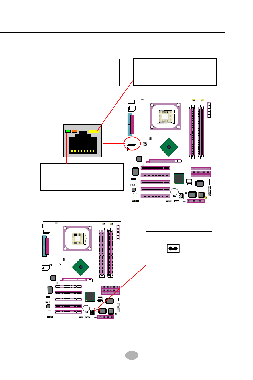
2-9.8 LAN Connector
One RJ45 connector is on board for network connection.
Yellow LED “On” to indicate
Network hub is in connection
with the system.
Green LED blinks to indicate
that data transmission is
undergoing in 10/100 Base T
mode.
2-9.9 Thermal Detector
RT3 is mounted
with Thermal Resistor
by default for detecting
system temperature.
RT3
Thermal Resistor RT3
Detector RT3: A thermal detector is mounted by default to connector
RT3 so as to detect the temperature of the system. What RT3 does
is to transmit the thermal signal to Hardware Monitor.
Orange LED blinks to indicate
that data transmission is
undergoing in 1000 Base T
mode.
36
SL-865Pro2-FGR
865PE
Intel
Intel 82865PE
BIOS
RTL
ALC655
LPT1
COM1
COM2
mPGA478B
PW1
+12V Power
HDD
IR
PWR
1
20
SPK RST
+
-
+
-
PWLED
LED
F
a
n
1
1
USB3
RJ45
(on top)
AGP1 (8X/4X)
ICH5
Intel
IDE1
IDE2
IDE3
FDC1
PCI1
PCI2
PCI3
PCI4
PCI5
for Dual-channel DDR 400/333/266MHz
F
a
n
2
PW2
1
JKB1
1
JBAT1
1
JFSB2
JFSB1
PS/2 Mouse
(on top)
PS/2 Keyboard
(
m
id
d
le
)
JAUD1
1
L
i
n
e
i
n
(
o
n
t
o
p
)
L
i
n
e
O
u
t
(
u
n
d
e
r
s
id
e
)
M
i
c
1
CD_IN1
VT6307
VIA
W83627HF
Winbond
USB4
DIMM1 DIMM2
DIMM3 DIMM4
SATA1
SATA2
PDC20378
Promise
1
USB2
USB1(2 ports)
1
IEEE1
10
F
a
n
3
IEEE
1394
VIA
VT6122
Li
Battery
JFSB3
ATA1
AUDIO1
Main Power
F
a
n
4
(2 ports)
RT3
82801EB
22
1
2
2
2
10
(underside)
LED1
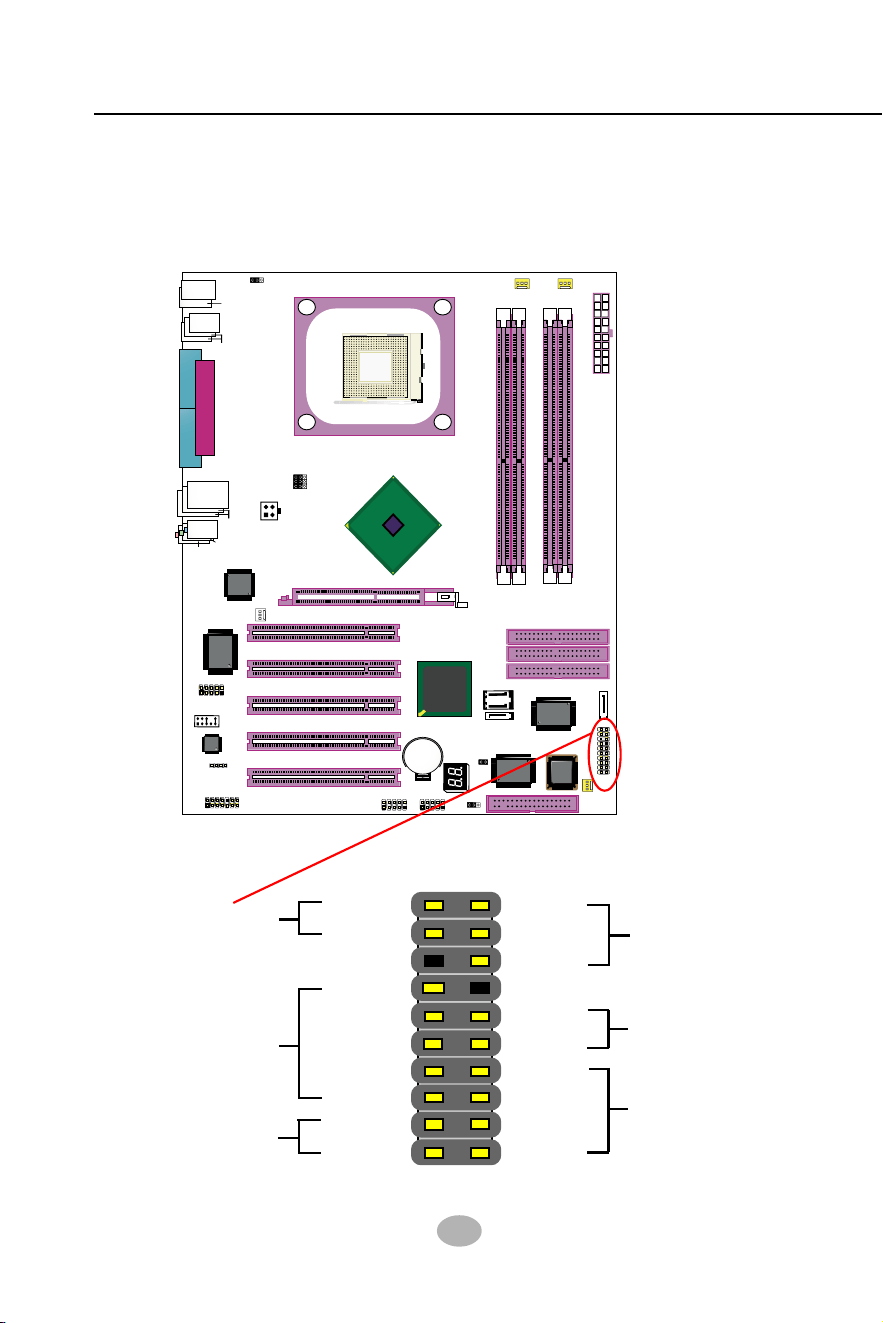
2-9.10 Complex Pin-header (Front Panel Connectors)
This complex Pin-header consists of the following connectors for vari-
ous supports. When you have fixed the mainboard to the case, join the
connectors of this Complex Pin-header to the case Front Panel.
(1)Power Switch
PLED-
NC
PLED+
RSTGND
RST1
SP1
NC
SP3
SPVCC
PWRBT#
PWRBT
IR_VCC
NC
IRRX
IRGND
IRTX
HDLED-
HDLED+
(2)Infrared(IR)
(3)HDD LED
Power LED (4)
Reset Switch(5)
Speaker (6)
37
Chapter 2 Hardware Setup
865PE
Intel
Intel 82865PE
BIOS
RTL
ALC655
LPT1
COM1
COM2
mPGA478B
PW1
+12V Power
HDD
IR
PWR
1
20
SPK RST
+
-
+
-
PWLED
LED
Fan1
1
USB3
RJ45
(on top)
AGP1 (8X/4X)
ICH5
Intel
IDE1
IDE2
IDE3
FDC1
PCI1
PCI2
PCI3
PCI4
PCI5
for Dual-channel DDR 400/333/266MHz
Fan2
PW2
1
JKB1
1
JBAT1
1
JFSB2
JFSB1
PS/2 Mouse
(on top)
PS/2 Keyboard
(
m
id
d
le
)
JAUD1
1
L
i
n
e
i
n
(
o
n
t
o
p
)
L
i
n
e
O
u
t
(
u
n
d
e
r
s
id
e
)
M
i
c
1
CD_IN1
VT6307
VIA
W83627HF
Winbond
USB4
DIMM1 DIMM2
DIMM3 DIMM4
SATA1
SATA2
PDC20378
Promise
1
USB2
USB1(2 ports)
1
IEEE1
10
Fan3
IEEE
1394
VIA
VT6122
Li
Battery
JFSB3
ATA1
AUDIO1
Main Power
Fan4
(2 ports)
RT3
82801EB
22
1
2
2
2
10
(underside)
LED1
(1) Power Switch Connector:
Connection: Connected to a momentary button or switch.
Function: Manually switching the system between “On” and “Soft
Off”. Pressing the momentary button for more than 4 seconds will
also turn the system off.
(2) IR Connector (Infrared Connector):
Connection: Connected to Connector IR on board.
Function: Supporting wireless transmitting and receiving module
on board.
(3) HDD LED Connector:
Connection: Connected to HDD LED.
Function: To supply power to HDD LED.
(4) Power LED Connector:
Connection: Connected to System Power LED.
Function: To supply power to “System Power LED”.
(5) Reset Switch Connector:
Connection: Connected to case-mounted “Reset Switch”.
Function: To supply power to “Reset Switch” and support system
reboot function.
(6) Speaker Connector:
Connection: Connected to the case-mounted Speaker.
Function: To supply power to the case-mounted Speaker.
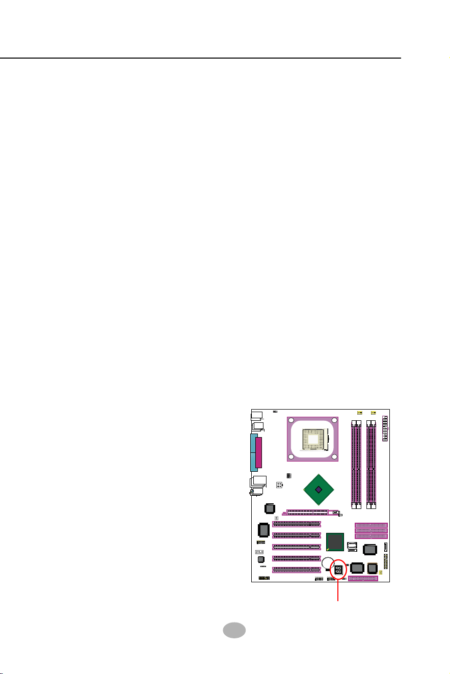
2-9.11 LED1: Debug LED
A Debug LED is built in on board to
display various digital messages
which stand for the running status of
the mainboard. The CheckPoint and
Beep Code List is enclosed in Ap-
pendices of this manual. Please re-
fer to the tables describing the type
of checkpoints for more information.
Debug LED
38
SL-865Pro2-FGR
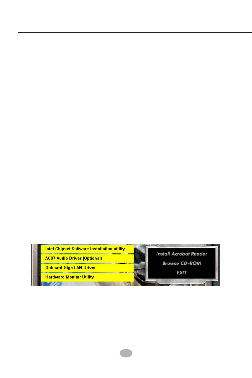
3-1 To Open up the Support CD
2. In case your system does not open the Support CD automatically,
please click to the following path to enter the Main Installation Menu:
D:\ Autorun.exe (assuming that your CD-ROM Drive is Drive D)
1. Please put the Support CD enclosed in your mainboard package into
the CD-ROM drive. In a few seconds, the Main Menu will automatic-
ally appear, displaying the contents to be installed for this series:
Chapter 3 Software Setup
3-1 To Open up the Support CD
3-2 To Install Intel Chipset Software Installation Utility
3-3 To Install AC’97 Audio Drivers
3-4 To install Gigabit Ethernet Drivers
3-5 To Install Hardware Monitor Utility
3-6 To Install Intel USB V2.0 Drivers
3-7 To install RAID Controller Driver
Drivers, Utilities and Software Installation
• Support CD:
This series of mainboards will be shipped with a Support CD which
contains those necessary driver files, Application Softwares and some
helpful utilities. It is a user-friendly, auto-run CD which will open itself
up in a CD-ROM automatically.
This chapter is devoted to describing the installations of all these es-
sential drivers and utilities on Windows 9X, Windows ME, Windows
2000 and Windows XP. And installation on Windows XP is taken as the
general illustration hereby.
3. Drivers may be updated from time to time in our web site. If you are
installing a newer driver than the one illustrated in this chapter, please
be aware that the illustration pictures might be different.
39
Chapter 3 Software Setup
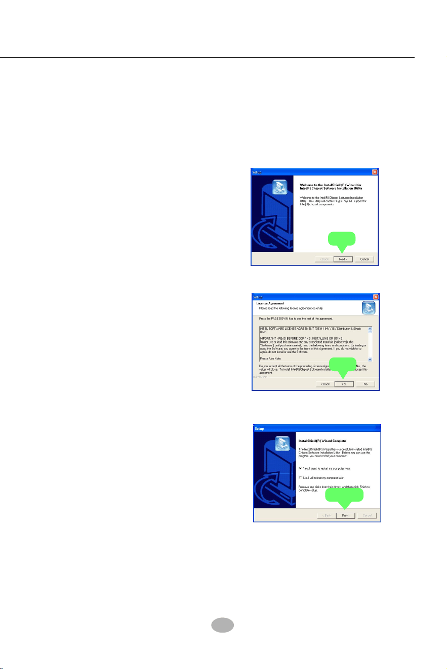
3-2 Intel Chipset Software Installation Utility
1. Following the procedures of opening the Support CD, click to “
Install Intel Chipset software installation Utility” to proceed.
2. The Intel Service Pack
InstallShield Wizard will
pop up to guide you to the
Intel Service pack installation.
Press “Next” button to
continue.
3. “Intel Software License
Agreement” screen will
appear, please click the
“Yes” button to agree with
the Licence Agreement and
continue.
4. After all the setup process
is finished, please restart
your computer by clicking
on “Finish” so as to take
the Utility into effect.
Next
Yes
Finish
40
SL-865Pro2-FGR
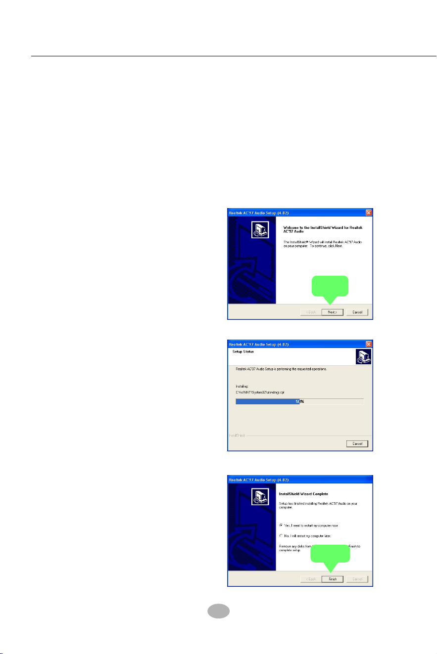
3-3 AC’97 Audio Driver Installation
Avance AC97 Audio Codec on board, AC’97 2.2 compatible stereo audio
code for PC multimedia systems. Avance AC’97 Audio Codec Driver is pro-
vided in Support CD for user’s installation.
4. After the setup process is
finished, please check the radial
button “Yes, I want to restart my
computer now.” And click
“Finish” to restart your system.
2. Instantly, the “installShield
Wizard” screen appears to
guide you through the “Avance
AC’97 Audio Setup””.
1. Following the procedures of opening the Support CD, click to “ AC’97
Audio Driver” to proceed.
3.Instantly, the Setup program
proceeds to install the softwares
which include AC’97 driver and
AVRack. (If you want to stop
setup, click the “Cancel”
button.)
3-3.1 Install AC’97 6-channel Audio Driver
Next
Finish
41
Chapter 3 Software Setup
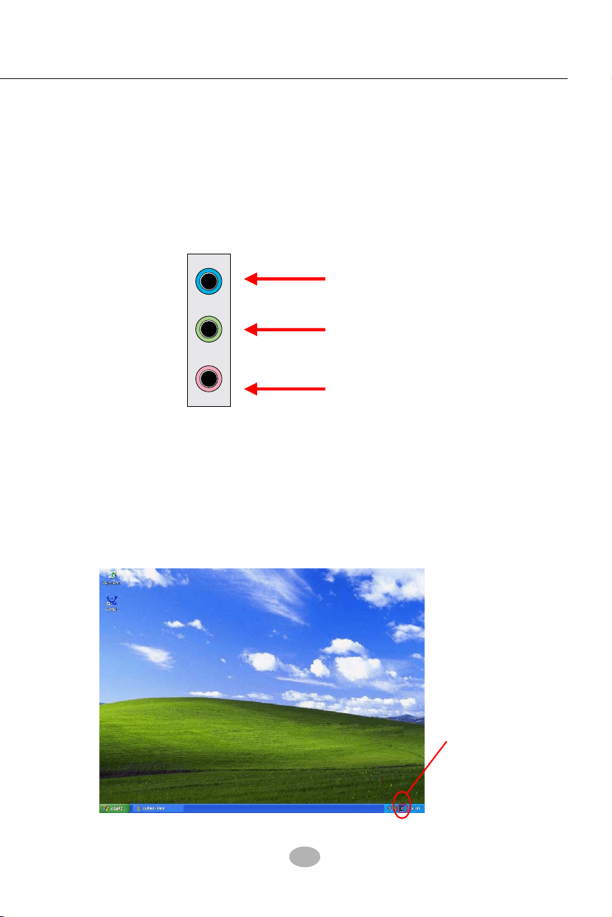
3-3.2 Verifying 6-channel Audio
After installation of AC’97 6-channel Codec, you must configure the 5.1
Speaker connection to enable the 6-channel audio.
2. After Connection is done, start your Windows system and double
click the Avance Sound Effect manager icon to enter 6-channel
configuration:
Sound Effect
Manager icon on
Windows XP
1. Connect your on-board Audio Connector to your 6-channel speakers
as depicted in the figure below:
Pale Green Connector
to Front Speaker
Pale Blue Connector
to Rear Speaker
Pale Pink Connector to
Center/Subwoofer Speaker
42
SL-865Pro2-FGR
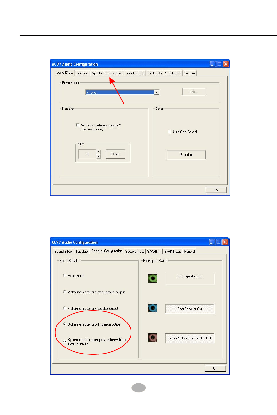
3. The AC’97 Audio Configuration” screen will pop out. Clikc the “Speaker
Configuration” bar with your mouse.
4. Instantly, the “Speaker Configuration” screen will pop out. Pick the
items “6-channel mode for 5.1 speakers output” and “ Synchronize
the phonejack switch with the speakers settings” and then click “OK”
to finish configuration.
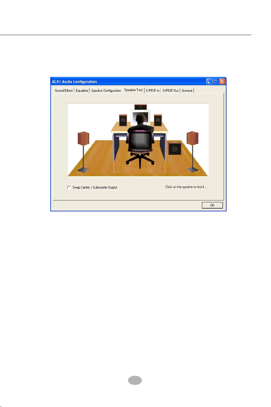
43
Chapter 3 Software Setup
5. At finishing the Speakers Configuration, you can also click the
“Speaker Test” bar on the screen to test the 6-channel performance.
The figure below is the “Speaker Test” screen with testing instructions
enclosed on it. Follow the instructions to perform the Speakers Test.
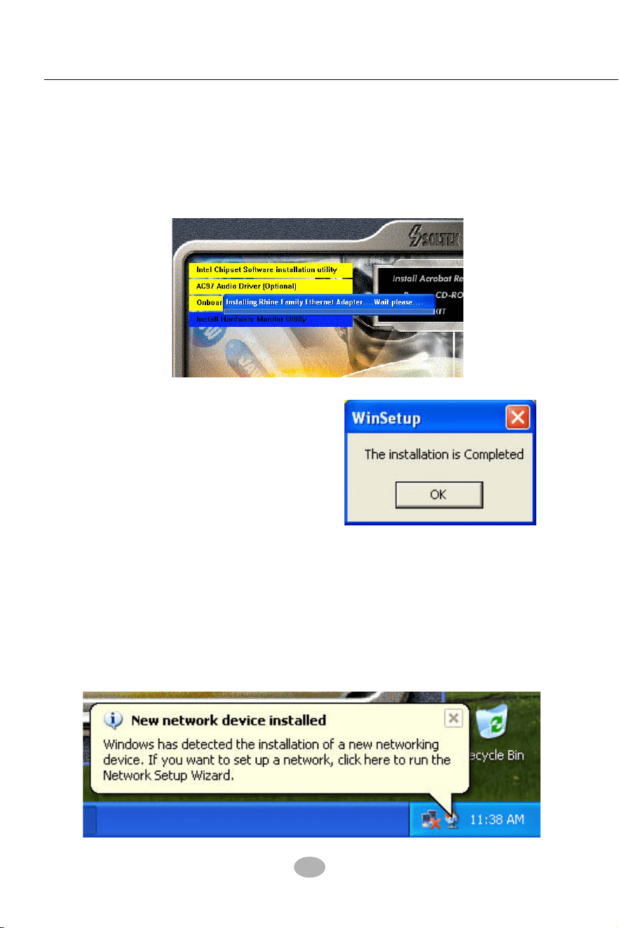
44
SL-865Pro2-FGR
3-4 To install Gigabit Ethernet Drivers
2. Instantly, “The installation is
completed” screen appears,
indicating that LAN Driver
setup is finished.
1. Following the procedures of opening the Support CD, click to “
Onboard Giga LAN Driver” to proceed.
3-4.1 Installation
3-4.2 Verification
After LAN Driver setup, a new networking icon will appear at the corner
of the “Start” screen of your system, indicating that a network channel
has been set up.
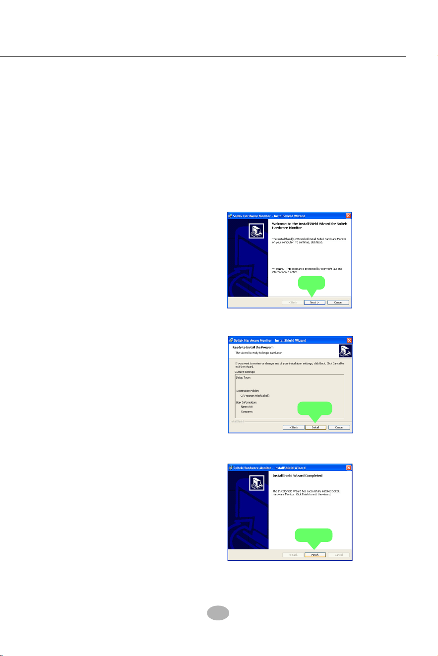
45
Chapter 3 Software Setup
3-5 To Install Hardware Monitor Utility
3-5.1 Installation
Hardware Monitor is built on this mainboard. Its installation is pro-
grammed to a fully automated mode on Windows 9X/Me/NT4/2000/
XP. Users can follow the model installation below for its installation
on various Windows System.
1.Following the procedures of opening the Support CD, click to “
Hardware Monitor Utility” to proceed.
2. The Soltek Hardware
Monitor InstallShield
Wizard will pop up to guide
you to the Intel Service pack
installation. Press “Next”
button to continue.
3. The InstallShield Wizard
screen will show the current
setting, please click the
“Install” button to continue.
4. After all the setup process
is finished, click “Finish” to
exit the wizard.
Next
Install
Finish
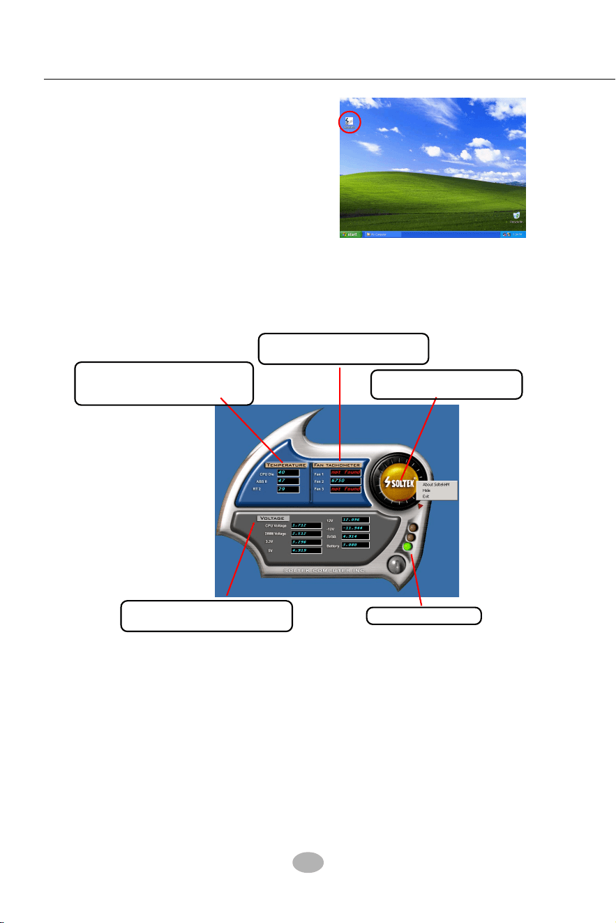
46
SL-865Pro2-FGR
2.Then the pop-up screen will show all information about CPU
Temperature, Fan Speed and various Voltages.
Showing the temperature(s), the
function of which is supported by
the mainboard.
Showing the Fan Speed(s) that
is supported by the mainboard.
Showing the Voltage(s) that is
supported by the mainboard.
Click on “Soltek” button to
display the function menu.
*Note: Not all items or functions showing in the above picture will
show up. Only those items or functions that are supported
by the mainboard will reveal themselves in the above
screen.
Status Warning LED
3-5.2 Verification
1. After installing Soltek Hardware
Monitor, double click “SoltekHM”
icon on the desktop to open the main
window of the Soltek Hardware
Doctor.
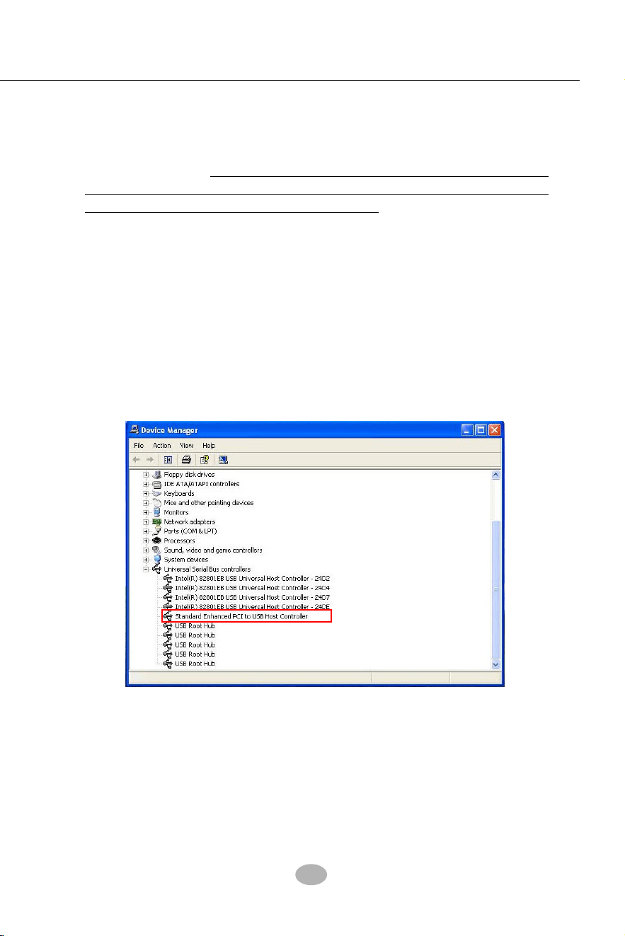
47
Chapter 3 Software Setup
3-6 To Install USB 2.0 Driver for Windows 2000/XP
USB V2.0 with its 480Mb/s transfer rate supports operating system
Windows 2000 and Windows XP via the Windows 2000 and Windows
XP Service Pack. For archieving Intel USB 2.0 support, users should
install the latest Service Pack for Windows 2000 or Windows XP. (intel
USB 2.0 does not support Windows 9X/ME.)
1. After installation of Intel Chipset software installation Utility in Windows
2000 or Windows XP, start to install the latest Service Pack version
into the operating system. The installation of the latest Service Pack
will support USB2.0 in Windows 2000 or Windows XP now.(The latest
Service Pack can be found in Microsoft Web Site.)
2. To verify USB2.0 installation, please enter “Device Manager” of “My
Computer”. On the “Device Manager” screen, you should be able to
see the item “Standard Enhanced PCI to USB Host Controller”,
verifying USB2.0 Driver is installed successfully.
3-7 To Install RAID Controller Driver
Please see Chapter 5 RAID System and RAID Driver Setup

48
SL-865Pro2-FGR
Chapter 4 AMI BIOS Setup
This Chapter includes the following topics :
4-1 About BIOS Setup
4-2 To Run BIOS Setup
4-3 About CMOS
4-4 The POST (Power On Self Test)
4-5 To Update BIOS
4-6 BIOS Setup
BIOS stands for Basic Input and Output System. It was once called
ROM BIOS when it was stored in a Read-Only Memory (ROM) chip
Now manufacturers would like to store BIOS in EEPROM which means
Electrically Erasable Programmable Memory. BIOS used in this series
of mainboard is stored in EEPROM, and is the first program to run when
you turn on your computer.
BIOS performs the following functions:
1. Initializing and testing hardware in your computer (a process called
“POST”, for Power On Self Test).
2. Loading and running your operating system.
3. Helping your operating system and application programs manage
your PC hardware by means of a set of routines called BIOS Run-
Time Service.
THE BIOS
Attention: The BIOS Setup is subject to constant update without further
notice to users. It is necessary for users to update the onboard BIOS
by the latest BIOS version provided in our web site: www.soltek.com.tw

Chapter 4 BIOS Setup
49
4-1 About BIOS Setup
BIOS setup is an interactive BIOS program that you need to run when:
1. Changing the hardware of your system. (For example: installing a
new Hard Disk etc.)
2. Modifying the behavior of your computer. (For example: changing
the system time or date, or turning special features on or off etc.)
3. Enhancing your computer’s behavior. (For example: speeding up
performance by turning on shadowing or cache)
4-2 To Run BIOS Setup
First access BIOS setup menu by pressing < DEL > key after “POST” is
complete ( before OS is loaded ). BIOS will then display the following
message:
DEL:SETUP
4-3 About CMOS
CMOS is the memory maintained by a battery. CMOS is used to store
the BIOS settings you have selected in BIOS Setup. CMOS also
maintains the internal clock. Every time you turn on your computer, the
BIOS Looks into CMOS for the settings you have selected and configures
your computer accordingly. If the battery runs out of power, the CMOS
data will be lost and POST will issue a “CMOS invalid” or “CMOS
checksum invalid” message. If this happens, you have to replace the
battery and check and configure the BIOS Setup for the new start.
4-4 The POST ( Power On Self Test )
POST is an acronym for Power On Self Test. This program will test all
things the BIOS does before the operating system is started. Each of
POST routines is assigned a POST code, a unique number which is
sent to I/O port 080h before the routine is executed.

50
SL-865Pro2-FGR
4-5 To Update BIOS
• System BIOS is incorporated into a Flash memory component. Flash
BIOS allows user to upgrade BIOS without the need to replace an EPROM
component.
• The Upgrade Utility can be loaded on a floppy diskette for upgrading
saving, and verifying the system BIOS. The Update Utility can also be run
from a hard disk drive or a network drive.
• It is highly recommended that you save a copy of the original mainboard
BIOS along with a Flash EPROM Programming utility (amiflash.exe) to a
bootable floppy disk so that you can reinstall the BIOS when in need.
• Normally, to update BIOS is unnecessary if the system is working fine.
Users should only update BIOS when incompatible problems are encoun-
tered or new features have to be added to system.
• “AMIFLASH.EXE” is a Flash EPROM Programming utility that updates
the BIOS by uploading a new BIOS file to the programmable flash ROM
on the mainboard. This program only works in DOS environment, the
utility can not be executed in win95/98, ME, NT WINDOWS 2000 or
Windows XP environment.
• Please follow the steps below for updating the sys-
tem BIOS:
Step 1. Please visit the board maker’s website, download the zip files
of the latest BIOS and AMI flash utility “amiflash.exe” for your
mainboard. After unzipping, the BIOS file format will be *.ROM, of which
“ * ” stands for the specific BIOS file name.
Step 2. Create a bootable diskette. Then copy the BIOS file and AMI
flash utility “amiflash.exe” into the diskette.
Step 3. Insert the diskette into drive A, boot your system from the
diskette.

Chapter 4 BIOS Setup
51
Step 4. Under “ A “ prompt, type “ amiflash *.ROM “ and then press
<Enter> to run BIOS update program. (*.ROM depends on your
mainboard model and version code. Instead of typing “*”, you should
type the specific file name for your specific mainboard). For example,
you may type “amiflash MP005.rom ”.
Step 5. When the message “Flash ROM Update Completed - Pass.”
appears, please restart your system.
Step 6. You will see a message “CMOS Memory Size Wrong” during
booting the system. Press <Del> or <F1> to run CMOS setup utility,
then reload “Load Failsafe Defaults” or “Load Optimal Defaults” and
save this change.
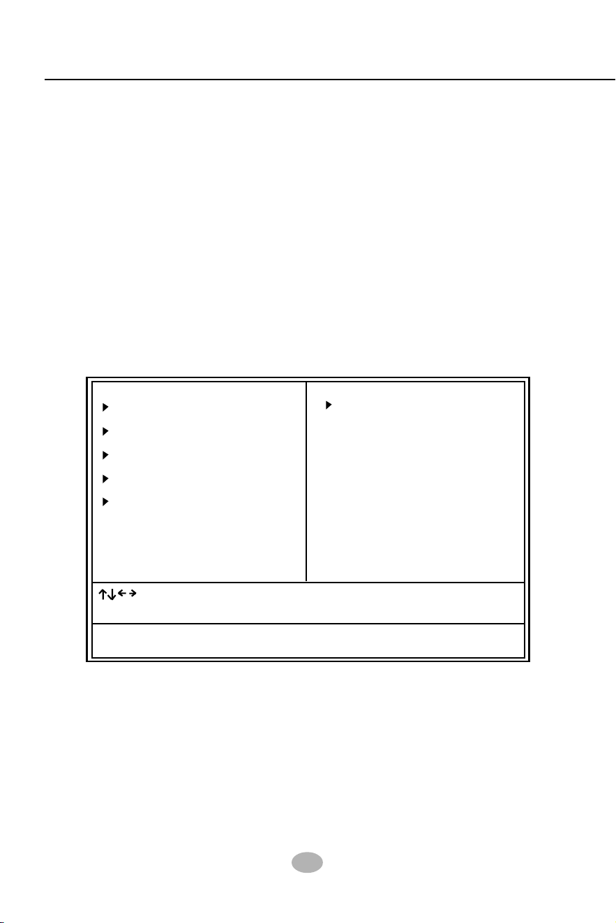
52
SL-865Pro2-FGR
4-6 BIOS SETUP --- CMOS Setup Utility
This mainboard comes with the AMI BIOS from American Megatrends
Inc. Enter the CMOS Setup Utility Main Menu by:
1. Turn on or reboot your system. After a series of diagnostic checks,
the following message will appear:
PRESS <Del> TO RUN SETUP
2. Press the <Del> key and the main program screen will appear as
follows.
3. Use the arrow keys on your keyboard to select an option, and press
<Enter>. Modify the system parameters to reflect the options installed
in your system.
4. You may return to the Main Menu anytime by pressing <Esc>.
5. In the Main Menu, “Save Changes and Exit” saves your changes and
reboots the system, and “Discard Changes and Exit” ignores your
changes and exits the program.
4-6.1 CMOS Setup Utility
CMOS Setup Utility - Copyright (C) 1985-2002, American Megatrends, Inc.
Standard BIOS Features
Advanced BIOS Features
Advanced Chipset Features
PCI/PNP Resource Management
Boot Configuration Features
BIOS Security Features
Load Optimal Defaults
Discard Changes
Sace Changes and Exit
Discard Changes and Exit
Configure Time and Date. Display System Information ...
: : Move Enter : Select +/- : Values F10: Save Esc: Exit F1: General Help
F7 : Previous Values F8 : Fail-Safe Defaults F9: Optimize Defaults

Chapter 4 BIOS Setup
53
6. In entering the Main option of the Main Menu, please use the func-
tions in the Function List to configure the setting:
: : Move Enter : Select +/- : Values F10: Save Esc: Exit F1: General Help
F7 : Previous Values F8 : Fail-Safe Defaults F9: Optimized Defaults
Use [Enter], [Tab] or [Shift-Tab] to select a field.
Use [+] or [-] to choose the options.
<F1>: “General Help” provides explanations of the hot-key functions
available.
<F7>: “Previous values” allows user to discard previous values or not.
<F8>: “Fail-safe defaults” allows user to load Fail-safe Defaults or not. Save
and Exit Setup.
<F9>: “Optimized Defaults” alows user to load Optimal Defaults or not.
Attention: The BIOS Setup is subject to constant update without further
notice to users. It is necessary for users to update the onboard BIOS
by the latest BIOS version provided in our web site: www.soltek.com.tw

54
SL-865Pro2-FGR
System Time 00 : 19 : 29
System Date Thu 12/04/2003
“Standard BIOS Features” allows users to configure Time and Date.
This menu also displays system information.
Run the Standard BIOS Features as follows:
Choose “Standard BIOS Features” from the Main Menu and press
<Enter>. The following screen will appear:
4-6.2 Standard BIOS Features
Standard BIOS Features
Help Item
System Overview
AMIBIOS
Processor
System Memory
Version : 08.00.09
Build Date : 12/03/03
ID : 1ABRQ011
Type : Intel(R) Pentium(R) 4 CPU 1500MHz
Speed : 1500MHz
Count : 1
Size : 256MB
CMOS Setup Utility - Copyright (C) 1985-2002, American Megatrends, Inc.
Use [Enter], [Tab] or [Shift-
Tab] to select a field.
Use [+] or [-] to configure
system Time.
: : Move Enter : Select +/- : Values F10: Save Esc: Exit F1: General Help
F7 : Previous Values F8 : Fail-Safe Defaults F9: Optimized Defaults
AMIBIOS/Processor/System memory
These three items only show the respective current statuses. They cannot be changed in the
BIOS Setup.
System Time
The BIOS shows the time of the day in the format: hh:mm:ss. Choose the field with the Arrow
keys and change the time with the Page Up/Page Down +/- keys.
System Date
The BIOS shows the date of the day in the format: mm:dd:yy :day of the Week. Choose the
field with the Arrow keys and change the value with the Page Up/Page Down +/- keys.
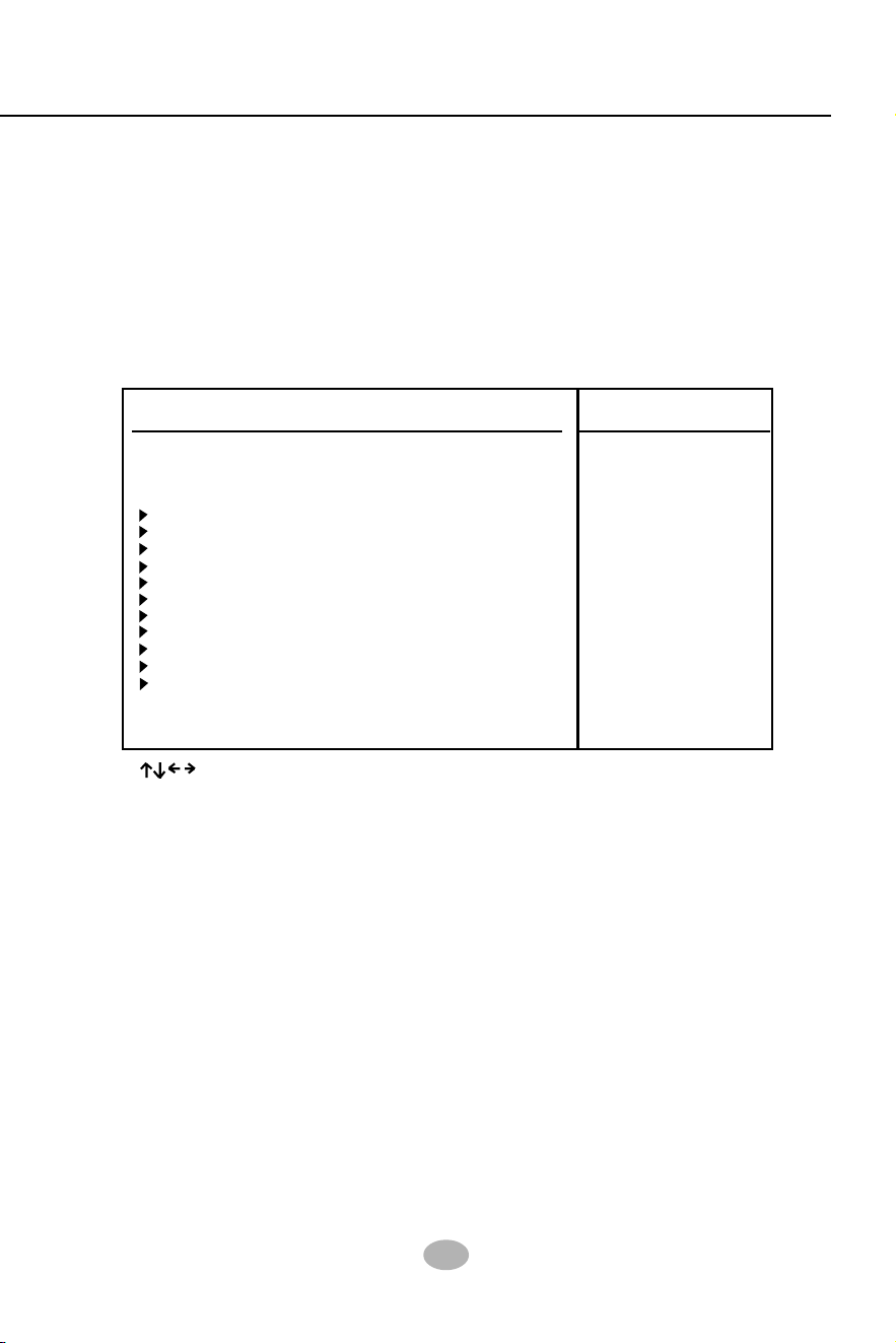
Chapter 4 BIOS Setup
55
4-6.3 Advanced BIOS Features
Advanced BIOS Features allows user to configure HDD, Floppy, Serial
Port, Parallel Port etc....
Run the Advanced BIOS Features as follows:
Choose “Advanced BIOS Features” from the Main Menu and a screen
with a list of options will appear:
Advanced BIOS Features
Help Item
Advanced Settings
Warning: Setting wrong values in below sections
may cause system to malfunction.
CMOS Setup Utility - Copyright (C) 1985-2002, American Megatrends, Inc.
CPU Configuration Press Enter
IDE Configuration Press Enter
Floppy Configuration Press Enter
SuperIO Configuration Press Enter
Hardware Health Configuration Press Enter
ACPI Configuration Press Enter
Clock Generator Configuration Press Enter
USB Configuration Press Enter
Voltage Control Press Enter
Power Management Press Enter
PCI Device Control Press Enter
: : Move Enter : Select +/- : Values F10: Save Esc: Exit F1: General Help
F7 : Previous Values F8 : Fail-Safe Defaults F9: Optimized Defaults

56
SL-865Pro2-FGR
4-6.3.1 CPU Configuration
Choose “CPU Configuration” in “Advanced BIOS Features” and press
<Enter>. The following sub-screen will appear for configuration:
Help Item
Configure advanced CPU settings
Sets the ratio between CPU
core clock and the FSB
Frequency.
Note: If an invalid ratio is set
in this field, BIOS will restore
it to previous state.
CPU Configuration
Manufacturer : Intel
Brand String : Intel(R) Pentium (R) 4 CPU 1500MHz
Frequency : 1500MHz
FSB Speed : 400MHz
Cache L1 :8KB
Cache L2 :512KB
Ratio Status : Locked
Ratio Actual Value : 8
Ratio CMOS Setting : 12
Max CPUID Value Limit: Disabled
Hyper Threading Technology Enabled
Manufacturer
BIOS shows the manufacturer of on-board CPU.
Brand String
BIOS shows the brand of on-board CPU.
Ratio Status
BIOS shows the current ratio (multiplier) status of
on-board CPU and FSB. For P4 CPUs, the ratio is
usually locked.
Cache L1/L2 BIOS shows the actual CPU internal Level 1/2 cache
size.
Ratio CMOS Setting
Setting unlocked FSB/CPU Ratio. If invalid ratio is
set , BIOS will restore it to previous state.
Ratio Actual Value BIOS shows the actual FSB/CPU ratio.
Frequency
BIOS shows the on-board CPU frequency.
FSB Speed BIOS shows the current Front Side Bus.
Max CPUID Value Limit
To enable/disable the maximum CPUID Value Limit.
Hyper Threading
Technology
BIOS shows the current status of Hyper Threading
Technology. If a Hyper Threading CPU is running
on board, this item will show “Enabled” status. If a
Hyper-threading CPU is not on-board, this item
shows “Disabled”.
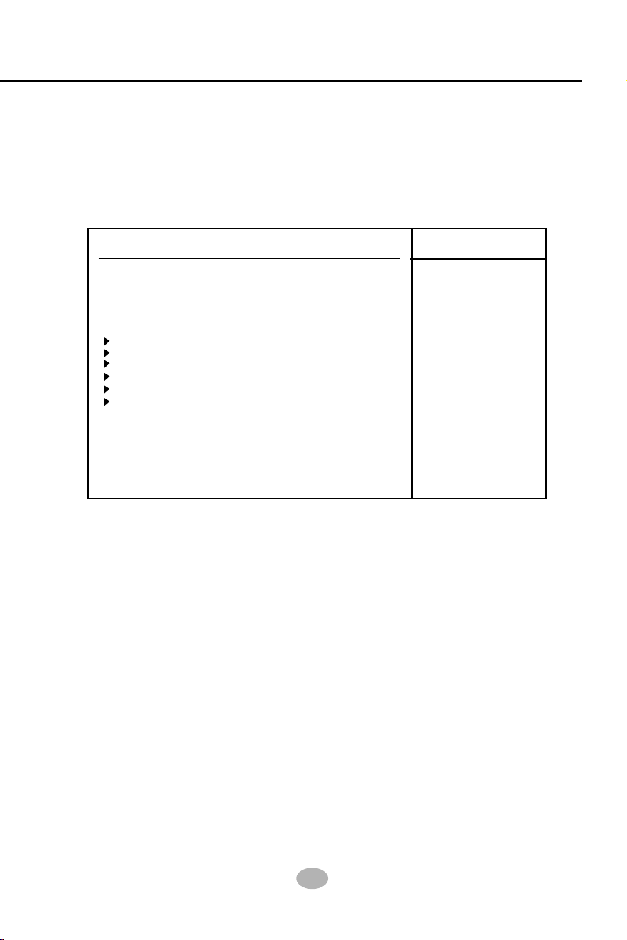
Chapter 4 BIOS Setup
57
4-6.3.2 IDE Configuration
Choose “IDE Configuration” in “Advanced BIOS Features” and press
<Enter>. The following sub-screen will appear for IDE Devices
configuration:
IDE Configuration
Help Item
IDE Configuration
IDE Configuration P/S-ATA (Auto)
S-ATA Running Enhanced Mode Yes
P-ATA Channel Selection Both
S-ATA Ports Definition P0-3rd./P1-4th
Primary IDE Master Hard Disk
Primary IDE Slave ATAPI CDROM
Secondary IDE Master Not Detected
Secondary IDE Slave Not Detected
Third IDE Master Not Detected
Fourth IDE Master Not Detected
Hard Disk Write Protect Disabled
IDE Detect Time Out 35
ATA(PI) 80Pin Cable Detection Host & Device

58
SL-865Pro2-FGR
IDE Configuration
Allows you to configurare IDE device mode.
Choices: Disabled; P/S-ATA (Auto); S-ATA Only; P/S-ATA(Win98/Me
P/S-ATA(Auto): Parallel/Serial ATA combined mode, providing the
following item for user’s configuration:
S-ATA Running Enhanced Mode (Combined Mode Option):
Yes: If “Yes”, configure the following:
P-ATA Channel Selection:
Primary; Secondary; Both;
S-ATA Ports Defination:
P0-3rd./P1-4th.; P0-4th./P1-3rd.
No: If “No”, configure the following:
P-ATA Channel Selection:
Primary; Secondary; Both;
4-6.3.2-1 IDE Configuration
S-ATA Only: for S-ATA running on board only; providing the following item
for user’s configuration:
S-ATA Ports Definition:
P0-1st./P1-2nd;
P0-2nd./P1-1st;
P/S-ATA(Win98/Me): for P/S-ATA in Win98/Me; providing the
following item for user’s configuration:
Combined Mode Option:
P-ATA 1st Channel;
S-ATA 1st Channel;
S-ATA Ports Definition:
P0-Master/P1-Slave;
P0-Slave/P1-Master;
Disabled: IDE Configuration disabled.
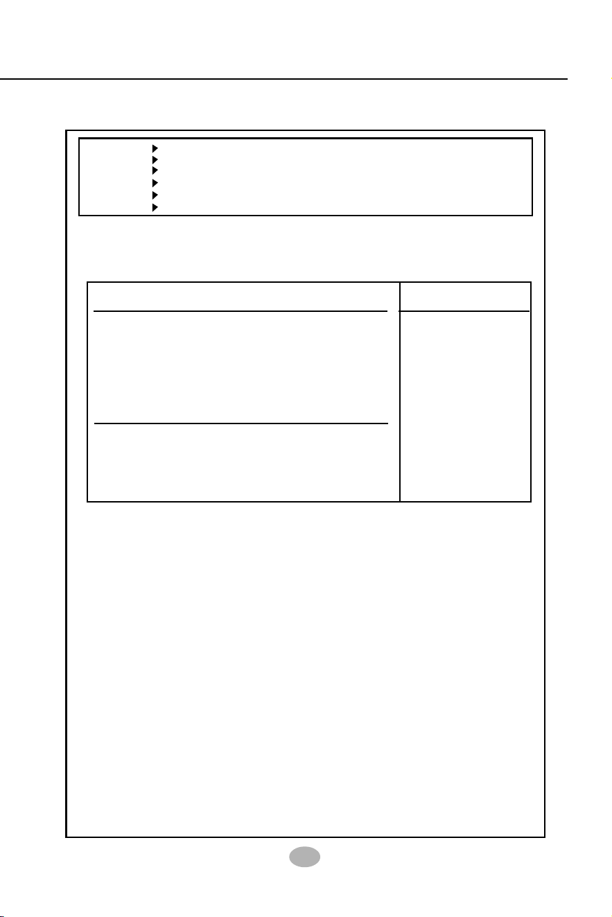
Chapter 4 BIOS Setup
59
4-6.3.2-2 Primary/Secondary IDE Master/Slave and Third/Fourth IDE
Master
Primary IDE Master Hard Disk
Primary IDE Slave ATAPI CDROM
Secondary IDE Master Not Detected
Secondary IDE Slave Not Detected
Third IDE Master Not Detected
Fourth IDE Master Not Detected
Help Item
Primary/(Secondary/Third/Fourth) IDE Master/(Slave)
Select the type of device
connected to the system.
Device : Hard Disk
Vendor : WDC WD400BB-00DEA0
Size : 40.0GB
LBA Mode : Supported
Block Mode : 16Sectors
PIO Mode : 4
Async DMA : MultiWord DMA-2
Ultra DMA : Ultra DMA-5
S.M.A.R.T. : Supported
Type Auto
LBA/Large mode Auto
Block (Multi-Sector Transfer) Auto
PIO Mode Auto
S.M.A.R.T. Auto
32Bit Data Transfer Disabled
Primary/(Secondary/Third/Fourth) IDE Master/(Slave)
If any IDE device is detected in any one of the above items press <Enter>
to reveal the IDE information:
Type
To select the types of the IDE devices:
Not Installed;
Auto: Setting type automatically
CD-ROM: ATAPI (Packet Interface) CD-ROM drive
ARMD: ATAPI Removable Media Device
LBA/Large mode
Block (Multi-Sector Transfer)
PIO Mode
To select or disable LBA/Large mode.
To select or disable Block Mode. The data transfer from and to the device occurs one
sector or multiple sectors at a time.
To select or disable PIO Mode.
Choices: Disabled; 1, 2, 3, 4
DMA Mode
To select DMA Mode.
Choices: Auto; SWDMAn; MWDMAn; UDMAn
S.M.A.R.T
32Bit Data Transfer
To auto-select (default) or disable 32Bit Data Transfer.
Allows you to enable / disable the Self Monitoring Analysis and Reporting Technology for the
hard disk.

60
SL-865Pro2-FGR
1. Choose “Floppy Configuration” in “Advanced BIOS Features” and
press <Enter>. The following sub-screen will appear for configuration:
4-6.3.3 Floppy Configuration
Help Item
Floppy Configuration
Select the type of floppy
drive connected to the
system.
Floppy A 1.44 MB 3.5 in
Floppy B Disabled
Floppy Configuration
Floppy A/B To set up floppy drive(s) in your system.
Choices : 360KB 5.25 in.; 1.2MB, 5.25 in.;
720KB, 3.5 in.; 1.44MB, 3.5 in.
2.88MB, 3.5 in.; Disabled
Hard Disk Write
Protect
Allows you to Enabled / Disable(default) Hard Disk
Write Protection
IDE Detect Time Out
(Sec)
Allows you to set time out for IDE Detection.
Choices: 0 - 35 seconds in 5 seconds stepping
ATA(PI) 80Pin Cable
Detection
Allows you to select ATA(PI) devices for 80Pin Cable
Detection. To set Host & Device allows onboard IDE
controller and IDE disk drive to detect the type of
IDE cable used.
Choices: Host & Device, Host, Device
4-6.3.2-3 Hard Disk Write Protect
4-6.3.2-4 IDE Detect Time Out
4-6.3.2-5 ATA(P) 80Pin Cable Detection

Chapter 4 BIOS Setup
61
4-6.3.4 Super IO Configuration
Choose “SuperIO Configuration” in “Advanced BIOS Features” and press
<Enter>. The following sub-screen will appear for configuration:
Help Item
Configure Win627THF Super IO Chipset
SuperIO Configuration
OnBoard Floppy
Controller
Allows you to enable / disable the Onboard Floppy
Controller.
Serial Port1 Address Allows you to set the Onboard Serial Port1 Address.
Choices: Disabled; 3F8/IRQ4; 3E8/IRQ4; 2E8/IRQ3;
Serial Port2 Address Allows you to set the Onboard Serial Port2 Address.
Choices: Disabled; 2F8/IRQ3; 3E8/IRQ4; 2E8/
IRQ3;
OnBoard Floppy Controller Enabled
Serial Port1 Address 3F8/IRQ4
Serial port2 Address 2F8/IRQ3
Serial port2 Mode Normal
OnBoard CIR Port Disabled
Parallel Port Address 378
Parallel Port Mode Normal
Parallel Port IRQ IRQ7
Serial Port 2 Mode
If Serial Port2 Address is not disabled, it allows you
to set the Serial Port 2 Mode. Choices:
-- Normal;
-- IrDA: Providing 2 items for configuration:
IR I/O Pin Select: SINB/SOUTB; IRRX/IRTX
IR Duplex Mode: Half Duplex; Full Duplex
-- ASK IR: Providing 2 items for configuration:
IR I/O Pin Select: SINB/SOUTB; IRRX/IRTX
IR Duplex Mode: Half Duplex; Full Duplex

62
SL-865Pro2-FGR
Parallel Port Address Allows you to configure Parallel Port Address.
Choices: Disabled; 378; 278; 3BC;
CIR Port IRQ
Allows you to set the onboard CIR Port IRQ for 2E0
or 3E0.
Choices: IRQ3; IRQ4; IRQ9; IRQ10; IRQ11
OnBoard CIR Port
Allows you to set the onboard CIR Port.
Choices: Disabled; 2E0; 3E0
-- Disabled: To disable this function;
-- 378: 2 items to configure for address 378:
--- Parallel Port Mode:
Normal;
Bi-Directional;
EPP:
EPP Version: 1.9; 1.7
ECP:
ECP Mode DMA Channel: DMA0; DMA1;
DMA3
--- Parallel Port IRQ: IRQ5; IRQ7

Chapter 4 BIOS Setup
63
4-6.3.5 Hardware Health Configuration
Hardware Health Configuration
1. Choose “Hardware Health Configuration” in “Advanced BIOS
Features” and press <Enter>. The following sub-screen will appear
for configuration:
Hardware Health Configuration Help Item
Enables Hardware Health
Monitoring Device.
: : Move Enter : Select +/- : Values F10: Save Esc: Exit F1: General Help
F7 : Previous Values F8 : Fail-Safe Defaults F9: Optimize Defaults
Fan1/2/3 Speed
Displaying the current speed of Chassis/CPU/Power
Fan.
CPU Core
Showing CPU core actual voltage value.
CPU Temperature Shows current CPU internal temperature.
1.5V/3.3V/+5.00V/+12V/
-12V/5VSB/Battery
Showing current voltage against the 1.5V/3.3V/
+12V/+5V/5VSB/Battery power supply.
System Temperature Shows current system temperature.
System Temperature : 34˚C/93˚F
CPU Temperature : 45˚C/113˚F
Fan1 Speed : 3125 RPM
Fan2 Speed : 3169 RPM
Fan3 Speed : N/A
CPU Core : 1.500 V
+1.50V : 1.516 V
+3.30V : 3.258 V
+5.00V : 5.094V
+12.0V : 12.074 V
-12.0V : -12.048 V
5VSB : 5.467 V
Battery : 3.444 V

64
SL-865Pro2-FGR
(Optional) USB Device
Wakeup From S3/S4
This item allows you to enable / disable the USB
device Wakeup function from S3/S4 mode.
Suspend mode This item allows you to select the Suspend mode.
You can select S3(STR) for suspending to DRAM if
your system supports this mode. Or you can select
S1 (POS) for Power on Suspend under ACPI mode.
Choices: S1(POS); S3(STR)(Optional);
General ACPI Configuration:
To press< Enter > on General ACPI Configuration will reveal the following
item(s).
(Optional) Repost
Video at S3 Resume
If STR mode is selected, this item allows you to
enable / disable this function.
Choices: Yes; No
ACPI Aware O/S Yes
General ACPI Configuration Press Enter
Advanced ACPI Configuration Press Enter
4-6.3.6 ACPI Configuration
ACPI Settings
ACPI Configuration
Choose “ACPI Configuration” in “Advanced BIOS Features” and press
<Enter>. The following sub-screen will appear for ACPI configuration:
Enables Hardware ACPI
support for Operating
System.
Enable: If OS supports
ACPI.
Disable: If OS Does not
support ACPI.
Help Item
ACPI Aware O/S Allows you to enable ACPI Aware O/S function if
your O/S supports ACPI. Windows XP, 2000, 98SE
all support ACPI. Choices:
Yes: If “Yes” it allows you to configure “General /
Advanced ACPI”.
No: If “No”, no “General/Advanced ACPI” to be
configured.

Chapter 4 BIOS Setup
65
ACPI 2.0 Support Allows you to enable / disable ACPI (Advanced Con-
figuration and Power Interface) 2.0 Support function.
Choices: Yes; No
ACPI APIC Support Allows you to enable / disable ACPI APIC (Advanced
Programmable Interrupt Controller) Support function.
APIC ACPI SCI IRQ If APIC ACPI Support is enabled (Yes), it allows you
to enable / disable APIC ACPI SCI IRQ function.
BIOS-->AML ACPI
table
Allows you to enable / disable BIOS-->AML ACPI
table function.
Headless mode Allows you to enable / disable Headless operation
mode through ACPI.
Advanced ACPI Configuration:
To press< Enter > on Advanced ACPI Configuration will reveal the
following item(s).
66
SL-865Pro2-FGR
4-6.3.7. Clock Generator Configuration
Choose “Clock Generator Configuration” in “Advanced BIOS Features”
and press <Enter>. The following sub-screen will appear for
configuration:
Help Item
Clock Generator Configuration
CPU Frequency Setting 200
AGP/PCI Frequency Setting Disabled
Spread Spectrum Disabled
Auto PCI Clock Disabled
Configure ICS ICS952603 Clock Generator
CPU Frequency
Setting
This item allows you to set CPU Clock.
Choices:
100MHz~132MHz is for 100MHz CPU;
133MHz~165MHz is for 133MHz CPU;
200MHz~260MHz is for 200MHz CPU;
Spread
Spectrum
This function will reduce the EMI (Electromagnetic
Interference) in your system. If you do not have an
EMI problem, leave this item disabled.
Choices: Disabled; 0.35%;0.50%; 0.75%; 1.00%
AGP/PCI Frequency
Setting
To set AGP/PCI Frequency.
Choices:
Disabled;
66.66/33.33 fixed;
72.73/36.36 fixed;
80.00/40.00 fixed;
Auto PCI Clock To enable/disable auto-detect PCI clock.

Chapter 4 BIOS Setup
67
4-6.3.8. USB Configuration
1. Choose “USB Configuration” in “Advanced BIOS Features” and
press <Enter>. The following sub-screen will appear for
configuration:
Module Version - 2.23.2-7.4
USB Devices Enabled :
None
USB Function 8 USB Ports
Legacy USB Support Enabled
USB 2.0 Controller Enabled
USB 2.0 Controller Mode FullSpeed
USB Configuration
USB Configuration
Enable USB host
controllers.
: : Move Enter : Select +/- : Values F10: Save Esc: Exit F1: General Help
F7 : Previous Values F8 : Fail-Safe Defaults F9: Optimized Defaults
Help Item
USB Function Allows you to set USB Function on the USB port(s).
Choices: 8 USB Ports; Disabled
Legacy USB Support Allows you to enable / disable the Legacy USB
support.
USB 2.0 Controller Allows you to enable/ disable the USB 2.0 Controller.
USB 2.0 Controller
Mode
Allows you to configure the USB 2.0 Controller Mode.
Choices: FullSpeed; HiSpeed.

68
SL-865Pro2-FGR
AGP Voltage Control 1.5V
DIMM Voltage Control 2.6V
CPU Voltage Control Auto
4-6.3.9. Voltage Control
Voltage Configuration
Voltage Control
1. Choose “Voltage Control” in “Advanced BIOS Features” and press
<Enter>. The following sub-screen will appear for configuration:
: : Move Enter : Select +/- : Values F10: Save Esc: Exit F1: General Help
F7 : Previous Values F8 : Fail-Safe Defaults F9: Optimized Defaults
Help Item
CPU Voltage
Control
Allows you to configure the CPU Voltage. Usually,
to raise CPU voltage will raise the chance of CPU
overclocking and yet risk damage of CPU.
Choices: Auto; 0.8500V ~1.8000V in 0.0125V step-
ping
AGP Voltage
Control
Allows you to configure the AGP Voltage.
Choices: 1.5V; 1.6V; 1.7V; 1.8V
DIMM Voltage
Control
Allows you to configure the DIMM Voltage.
Choices: 2.6V; 2.7V; 2.8V; 2.9V

Chapter 4 BIOS Setup
69
Power Management/APM Enabled
Video Power Down Mode Suspend
Hard Disk Power Down Mode Suspend
Standby Time Out Disabled
Suspend Time Out Disabled
Power Button Mode On/Off
Restore on AC Power Loss Power Off
Resume On Ring Disabled
Resume On LAN/PME# Disabled
Resume On RTC Alarm Disabled
4-6.3.10. Power Management
APM Configuration
Power Management
Choose “Power Management” in “Advanced BIOS Features” and press
<Enter>. The following sub-screen will appear for configuration:
Enable or disable APM.
: : Move Enter : Select +/- : Values F10: Save Esc: Exit F1: General Help
F7 : Previous Values F8 : Fail-Safe Defaults F9: Optimized Defaults
Help Item
Power Management/
APM
Allows you to enable / disable the Power manage-
ment / Advanced Power Management function.
Video Power Down
Mode
Allows you to select the Video Power Down Mode.
Choices: Disabled; Standby; Suspend
Hard Disk Power
Down Mode
Allows you to select the Hard Disk Power Down
Mode.
Choices: Disabled; Standby; Suspend
Standby Time Out
(Minute)
To set the duration of Standby Time Out.
Choices: Disabled; 1; 2; 4; 8; 10; 20; 30; 40; 50; 60
Suspend Time Out
(Minute)
To set the duration of Suspend Time Out.
Choices: Disabled; 1; 2; 4; 8; 10; 20; 30; 40; 50; 60
Restore on AC/Power
Loss
Allows you to set the restore state from AC/Power
Loss.
Choices: Last State; Power Off (default); Power On
Power Button Function
Allows you to set power Button function.
Choices: On/Off (default); Suspend

70
SL-865Pro2-FGR
Resume On RTC Alarm Allows you to enable / disable (default)the Resume
On RTC Alarm function.
RTC Alarm Date / Hour
/ Minute / Second
If resume On RTC Alarm is enabled, this field al-
lows you to set the Alarm date Hour, Minute and
second.
Date Choices: Every Day; 01 ~ 31
Hour Choices: 00 ~ 23
Minute Choices: 00 ~ 59
Second Choices: 00 ~ 59
Resume on Ring
Allows you to enable / disable (default)the Resume
on Ring Signal function.
An input signal on the serial Ring Indicator (RI) Line
(in other words, an incoming call on the modem)
awakens the system from a soft off state.
Resume on LAN/PME# Allows you to enable / disable (default)the Resume
on LAN/PME# function.
Promise RAID Enabled
IEEE 1394 Enabled
GIGA LAN Enabled
4-6.3.11. PCI Device Control
PCI Device Cobtrol
PCI Device Control
Choose “PCI Device Control” in “Advanced BIOS Features” and press
<Enter>. The following sub-screen will appear for configuration:
: : Move Enter : Select +/- : Values F10: Save Esc: Exit F1: General Help
F7 : Previous Values F8 : Fail-Safe Defaults F9: Optimized Defaults
Help Item
Promise RAID To enable / disable the Promise RAID Controller
IEEE 1394 To enable / disable the IEEE 1394 interface.
GIGA LAN To enable / disable the giga LAN Controller.
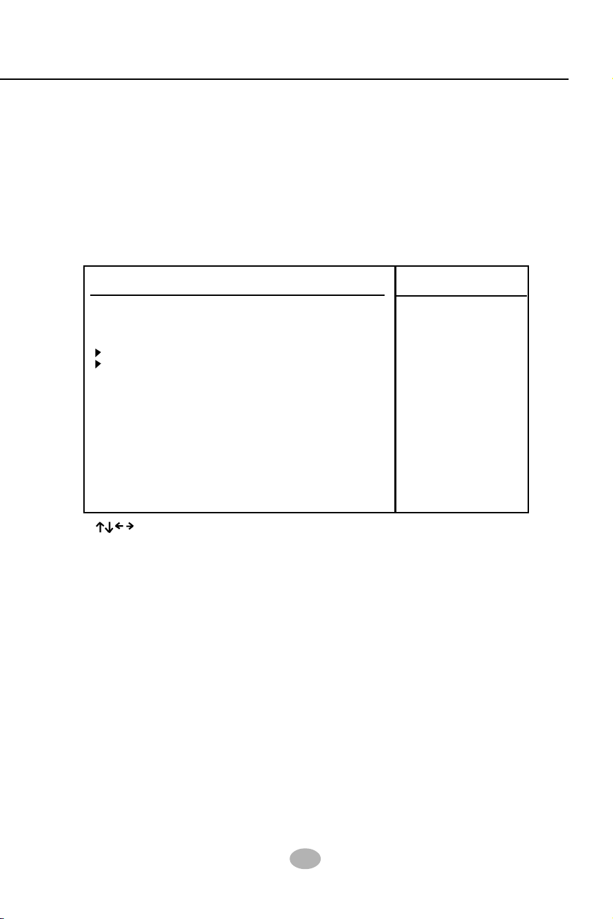
Chapter 4 BIOS Setup
71
4-6.4 Advanced Chipset Features
Advanced Chipset Features
Help Item
Advanced Chipset Settings
Warning: Setting wrong values in below sections
may cause system to malfunction.
CMOS Setup Utility - Copyright (C) 1985-2002, American Megatrends, Inc.
NorthBridge Configuration Press Enter
SouthBridge Configuration Press Enter
: : Move Enter : Select +/- : Values F10: Save Esc: Exit F1: General Help
F7 : Previous Values F8 : Fail-Safe Defaults F9: Optimized Defaults
Advanced Chipset Features is used to modify the values of chipset
buffers. These buffers control the system options.
Run the Advanced Chipset Features as follows:
Choose “Advanced Chipset Features” from the Main Menu and a
list of option will appear:
Options for NBEnable
USB host controllers.

72
SL-865Pro2-FGR
DRAM Frequency Auto
Configure DRAM Timing by SPD Enabled
Memory Hole Disabled
Init. Graphic Adapter Priority AGP/PCI
Graphics Aperture Size 64MB
4-6.4.1 NorthBridge Configuration
NorthBridge Configuration
Choose “NorthBridge Configuration” in “Advanced Chipset Features”
and press <Enter>. The following sub-screen will appear for
configuration:
Help Item
DRAM Frequency Allows you to set the current SDRAM frequency.
Choices: Auto; 266MHz; 333MHz; 400MHz

Chapter 4 BIOS Setup
73
AGP Aperture Size Series of options are available: 4, 8, 16, 32, 64, 128,
256MB. Memory mapped and graphics data struc-
tures can reside in a Graphics Aperture. This area
is like a linear buffer. BIOS will automatically report
the starting address of this buffer to the O.S. The
default setting is 64MB.
Memory Hole Allows you to enable / disable (default) the support
of Memory Hole which is reserved for ISA card.
Choices: Disabled; 15MB-16MB
Init. Graphics Adapter
Priority
Allows you to select the initial Graphics Adapter.
Choices: AGP/PCI(default); PCI/AGP;
DRAM RAS# to CAS#
Delay
With SDRAM Timing by SPD disabled, you can se-
lect the SDRAM RAS# to CAS# delay cycle
manually.
Choices: 2 Clocks; 3 Clocks; 4 Clocks
DRAM Precharge
Delay
Allows you to set the SDRAM Precharge Delay
cycle.
Choices: 5 Clocks; 6 Clocks; 7 Clocks; 8 Clocks
DRAM Burst Length With SDRAM Timing by SPD disabled, you can se-
lect the SDRAM Burst length manually.
Choices: 8; 4
DRAM CAS# Latency With SDRAM Timing by SPD disabled, you can se-
lect the SDRAM CAS# (Column Address Strode)la-
tency manually.
Choices: 2 Clocks; 2.5 Clocks; 3 Clocks
DRAM RAS#
Precharge
With SDRAM Timing by SPD disabled, you can se-
lect the SDRAM RAS# (Row Address Strode)
Precharge cycle manually.
Choices: 2 Clocks; 3 Clocks; 4 Clocks
Configure DRAM
Timing by SPD
SPD (Serial presence detect) is a device in memory
module for storing the module information such as
DRAM timing and chip parameters. If this option is
enabled, BIOS will access SPD automatically to
configure module timing. If disabled, the following
items will appear for user’s configuration:

74
SL-865Pro2-FGR
4-6.4.2 SouthBridge Configuration
OnBoard AC’97 Audio Auto
SouthBridge Configuration
1. Choose “SouthBridge Configuration” in “Advanced Chipset Fea-
tures” and press <Enter>. The following sub-screen will appear for
configuration:
: : Move Enter : Select +/- : Values F10: Save Esc: Exit F1: General Help
F7 : Previous Values F8 : Fail-Safe Defaults F9: Optimized Defaults
Help Item
Onboard AC‘97 Audio
Allows you to disable AC’ 97 Audio.
Choices: Auto (default); Disabled

Chapter 4 BIOS Setup
75
PCI Latency Timer (PCI
Clocks)
Allows you to set the PCI Latency Time.
Choices: 32(default); 64; 96; 192; 128; 160; 192;
224; 248;
Plug & Play O/S Allows you to configure the PNP devices by BIOS
or O/S.
Choices: No(by BIOS) (default); Yes(by O/S)
Allocate IRQ to PCI
VGA
Allows you to assign IRQ to PCI VGA card if card
requests IRQ.
Choices: Yes(default); No
4-6.5 PCI/PNP Resource Management
PCI/PNP Resource Management
Help Item
Advanced PCI/PNP Settings
Warning: Setting wrong values in below sections
may cause system to malfunction.
CMOS Setup Utility - Copyright (C) 1985-2002, American Megatrends, Inc.
Plug & Play O/S No
PCI Latency Timer 32
Allocate IRQ to PCI VGA Yes
Palette Snooping Disabled
PCI IDE BusMaster Disabled
OffBoard PCI/ISA IDE Card Auto
IRQ3 Available
IRQ4 Available
IRQ5 Available
IRQ7 Available
IRQ9 Available
IRQ10 Available
IRQ11 Available
IRQ14 Available
IRQ15 Available
DMA Channel 0 Available
DMA Channel 1 Available
DMA Channel 3 Available
DMA Channel 5 Available
DMA Channel 6 Available
DMA Channel 7 Available
Reserved Memory Size Disabled
: : Move Enter : Select +/- : Values F10: Save Esc: Exit F1: General Help
F7 : Previous Values F8 : Fail-Safe Defaults F9: Optimized Defaults
PCI/PNP Resource Management allows you to modify the system’s
power saving functions.
1. Choose “PCI/PNP Resource Management” from the Main Menu and
a screen with a list of options will appear:
No: lets the BIOS
configure all the devices
in the system.
Yes: lets the operating
system configure Plug
and Play (PnP) devices
not required for boot if
your system has a Plug
and Play operating
system.

76
SL-865Pro2-FGR
4-6.6 Boot Configuration Features
Boot Configuration Setup allows you to modify the system’s boot
settings.
Choose “Boot Configuration Setup” from the Main Menu and a screen
with a list of options will appear:
Boot Configuration Setup
Help Item
Boot Settings
CMOS Setup Utility - Copyright (C) 1985-2002, American Megatrends, Inc.
: : Move Enter : Select +/- : Values F10: Save Esc: Exit F1: General Help
F7 : Previous Values F8 : Fail-Safe Defaults F9: Optimized Defaults
Configure Settings
during System Boot.
Boot Setting Configuration Press Enter
Boot Device Priority Press Enter
Palette Snooping This option allows the BIOS to preview VGA status,
and to modify the information delivered from the
feature Connector of the VGA card to MPEG card.
This option can solve the display inversion to black
after you have used a MPEG card.
PCI IDE BusMaster Allows you to enable / disable(default) the PCI IDE
Bus Master function.
OffBoard PCI/ISA IDE
Card
Some PCI IDE cards may require this to be set to
the PCI slot number that is holding the card.
Choices: Auto; PCI Slot1; PCI Slot2; PCI Slot3; PCI
Slot4; PCI Slot5;
IRQ 3/4/5/7/9/10/11/14/
15
Allows you to specify available IRQs to be used by
PCI/PNP devices.
Choices: Available(default); Reserved
DMA 0/1/3/5/6/7 Allows you to specify available DMAs to be used by
PCI/PNP devices.
Choices: Available(default); Reserved
Reserved Memory Size Allows you to specify memory size to reserve for
legacy ISA devices.
Choices: Disabled(default); 16K; 32K; 64K

Chapter 4 BIOS Setup
77
Bootup Num-lock Allows you to toggle between On (default) or Off to
control the state of the NumLock keys when the
system boots. If On, the numeric keypad is in nu-
meric mode. If off, the numeric keypad is in cursor
control mode.
4-6.6.1 Boot Settings Configuration
Choose “Boot Settings Configuration” in “Boot Configuration Setup” and
press <Enter>. The following items will appear for onfiguration:
Quick Boot
Allows you to enable (default)/ disable quick boot of
your system. If enabled, BIOS will skip certain tests
while booting. This will decrease the time needed to
boot the system.
AddOn ROM Display
Mode
If “Force BIOS” (default) is chosen, the vendor’s
logo screen will be followed by the “AddOn ROM”
initial screen (the screen showing the add-on card
BIOS message). If “Keep Current” is chosen, no
“Add-On ROM” screen is followed.
Quiet Boot
The bootup screen displays normal POST messages
with Disabled selected; the bootup screen displays
OEM Logo instead of POST messages with Enabled
selected.
Choices: Enabled; Disabled
Help Item
Boot Settings
Quick Boot Enabled
Quiet Boot Disabled
AddOn ROM Display Mode Force BIOS
Bootup Num-Lock On
PS/2 Mouse Support Auto
Wait For ‘F1’ If Error Enabled
Hit ‘DEL’ Message Display Enabled
Interrupt 19 Capture Disabled
Boot Configuration Setup

78
SL-865Pro2-FGR
4-6.6.2 Boot Device Priority
Choose “Boot Device Priority” in “Boot Configuration Setup” and press
<Enter>. The bootable devices installed on board will appear and are
allowed to assign the Boot Priority.
1st/2nd Boot Device Allows you to set (by pressing <Enter>) floppy or
IDE devices already installed to be the 1st/2nd boot
device.
Choices: Disabled; Device(s) installed
PS/2 Mouse Support Enabled (default), PS/2 mouse is supported. Disabled,
PS/2 Mouse is not supported. If “Auto” is set, the system
will auto detect the PS/2 Mouse.
Wait For ‘F1’ If Error Allows you to hit F1 key when errors occur.
Choices: Enabled(default); Disabled
Hit ‘DEL’ Message
Display
When enabled, the system will show “Press DEL
key to run Setup in POST.
Choices: Enabled(default); Disabled
Interrupt 19 Capture Allows option ROMs to trap interrupt 19.
Choices: Enabled; Disabled(default)
Help Item
Boot Device Priority
Configure Settings
during System Boot.
1st Boot Device 1st FLOPPY DRIVE
2nd Boot Device PM-WDC WD400BB-00
Boot Device Priority
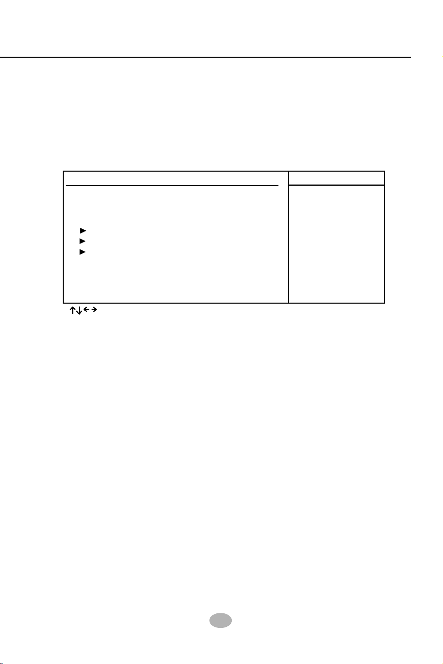
Chapter 4 BIOS Setup
79
Supervisor Password : Not Installed
User Password : Not Installed
Change Supervisor Password Press Enter
Change User Password Press Enter
Clear User Password Press Enter
Boot Sector Virus Protection Disabled
4-6.7. Boot Security Features
Boot Security Features allows you to modify the system’s boot security
settings.
Choose “Boot Security Features” from the Main Menu and a screen
with a list of options will appear:
Boot Security Features
CMOS Setup Utility - Copyright (C) 1985-2002, American Megatrends, Inc.
: : Move Enter : Select +/- : Values F10: Save Esc: Exit F1: General Help
F7 : Previous Values F8 : Fail-Safe Defaults F9: Optimized Defaults
Help Item
Security Settings
Install or Change the
password.
4-6.7.1. Supervisor Password
To show the status of Supervisor Password. “Installed” is displayed when
supervisor password is set up. Otherwise, “Not Installed” is displayed.
4-6.7.2. User Password
To show the status of User Password. “Installed” is displayed when
supervisor password is set up. Otherwise, “Not Installed” is displayed.

80
SL-865Pro2-FGR
This option allows you to set a new Supervisor password for the system:
1. Choose “Change Supervisor Password” in the “BIOS Security Fea-
tures” and press <Enter>. Then the following message appears:
[ Enter new supervisor password ]
2. The first time you run this option, enter your password up to 6 char-
acters and press <Enter>. (The screen does not display the entered
characters.)
3. After you enter the password, the following message appears, prompt-
ing you to confirm the password:
[ Confirm New Password ]
4. Enter the same password “exactly” the same as you have just typed
to confirm the password and press <Enter>.
5. The following message appears to confirm the new password setup.
6. Then press any key to continue your CMOS Setup. To save the pass-
word setup, you should press “Save Changes and Exit” and choose
“OK” to exit and save setup.
4-6.7.3 Change Supervisor Password
7. If you enter a new password into the box, you will be using this new
password after you have finished and saved this new setup. Instead,
if you press <Enter> before you enter any new password into the
instruction box, another message box appears, telling you that you
have disabled the Supervisor Password. That means, no password
is set for either entering BIOS Setup or system:
[ Password installed ]
[OK]
[ Password uninstalled ]
[OK]
User Access Level Allows you to set four different Access Levels when
Supervisor Password has been set.
Choices: Full Access; Limited; View Only; No Ac-
cess
Note: “User Access Level” and “Password Check” will appear when “Su-
pervisor Password” has been set.

Chapter 4 BIOS Setup
81
4-6.7.4 Change User Password
This option allows you to set a new User password for the system:
1. Choose “Change User Password” in the “BIOS Security Features”
and press <Enter>. Then the following message appears:
[ Enter New Password ]
2. The first time you run this option, enter your password up to 6 char-
acters and press <Enter>. (The screen does not display the entered
characters.)
3. After you enter the password, the following message appears, prompt-
ing you to confirm the password:
[ Confirm New Password ]
4. Enter the same password “exactly” the same as you have just typed
to confirm the password and press <Enter>.
5. The following message appears to confirm the new password setup.
6. Then press any key to continue your CMOS Setup. To save the pass-
word setup, you should press “Save Changes and Exit” and choose
“OK” to exit and save setup.
1. To remove the current user password, choose “Clear User Password”
and press <Enter>. An instruction box appears on the screen, assur-
ing to clear User Password:
2. Then choose [OK] and press <Enter>. The User Password is suc-
cessfully removed.
4-6.7.5. Clear User Password
[ Password installed ]
[OK]
Clear User Password?
[OK] [Cancel]
82
SL-865Pro2-FGR
Password Check Allows you to set BIOS to check up password with a
password prompt at BIOS Setup or whenever re-
starting system. This option will appear when you
have set Supervisor Password or User Password.
Choices: Setup (default); Always
Boot Sector Virus
Protection
When enabled, you receive a warning message if a
program (specifically, a virus) attempts to write to
the boot sector or the partition table of the hard disk
drive.
You should then run an antivirus program. Keep in
mind that this feature protects only the boot sector,
not the entire hard drive.
NOTE: Many disk diagnostic programs that access the boot
sector table can trigger the virus warning message. If you
plan to run such a program, we recommend that you dis-
able the virus warning.
4-6.7.6 Boot Sector Virus Protection
When you press <Enter> on this item, you will get a confirmation dialog
box with a message similar to:
Press <Enter> now to load Optimal values for all the Setup options.
4-6.8 Load Optimal Defaults
[ Load Optimal Defaults ?]
[OK] [Cancel]

Chapter 4 BIOS Setup
83
Discard Changes option allows you to exit (or not exit) the Setup Utility
without saving the modifications that you have specified. Highlight this
option on the Main Menu and press <Enter> and the following message
appears:
Follow the message and press <Enter> key to exit CMOS Setup and
restart system.
Discard Changes and exit setup?
[OK] [Cancel]
4-6.11 Discard Changes and Exit
Discard Changes?
[OK] [Cancel]
Discard Changes option allows you to cancel the modifications that you
have specified in the Setup Utility. Highlight this option on the Main
Menu and press <Enter> and the following message appears:
4-6.9 Discard Changes
4-6.10 Save Changes and Exit
Save Changes and Exit allows you to save all modifications you have
specified into the CMOS memory. Highlight this option on the Main Menu
and press <Enter>. The following message appears:
Press <Enter> key to save the configuration changes and exit CMOS
Setup to restart your system.
Saving configuration changes and exit setup?
[OK] [Cancel]
Follow the message and press <Enter> key to cancel the modifications
that you have specified.

84
SL-865Pro2-FGR
Chapter 5 RAID & RAID Driver
This Chapter is to introduce the SATA RAID / SATA
RAID + PATA RAID Configurations with PDC20378 :
Promise RAID (Redundant Array of Independent Disks) Controller PDC
20378 is to provide RAID configuration of RAID 0, RAID 1, and RAID
0+1 modes, while it also support. RAID Drivers are enclosed in a
Driver CD as well as a Floppy diskette to support various RAID systems
(Windows 98SE/Me/2000/XP) setup.
Promise RAID Controller PDC20378
5-0 About Disk Array................................................................... 85
5-0-1 Disk Array Interpretation.......................................................... 85
5-0-2 Disk Array Member .................................................................... 85
5-0-3 Disk Array Types Supported by PDC20378 ........................... 85
5-1. SATA RAID and PATA RAID Layout on Board ............. 86
5-2. First Step to Set up RAID - Populate Disk Drives.......... 86
5-3. To Enter RAID BIOS ........................................................... 86
5-4. To Enter the Main Menu of FastBuild Utility ................. 87
5-5. View Drive Assignment before RAID Setup .................... 88
5-6. Enter “Auto Setup” for RAID Setup ................................ 88
5-7. Choose “ Security” for RAID 0+1 (Stripe/Mirror) ........ 89
5-8. Press <Ctrl-Y> to Save the Choice .................................... 89
5-9. Create RAID Only / Create and Quick Initialize ........... 90
5-10. Array Created and View Drives Assignments ............... 90
5-11. Enter [Define Array] to see the RAID Mode ................. 91
5-12. After Array creation, Press [Esc] to exit ........................ 91
5-13. To Install Promise RAID Driver ...................................... 92
To Install RAID Driver on Windows 2000/XP/2003........................ 92
5-14. To Install Promise Array Management (PAM) ............. 95
5-15. To manage Array System by PAM................................... 96

Chapter 5 RAID & RAID Driver
85
5-0 About Disk Array
5-0-1 Disk Array Interpretation
A “Disk Array” is formed from a group of 2 or more disk drives with the
RAID (Redundent Array of Independent Disks) technology. The aim of
a Disk Array is to provide better perfornance and/or data fault tolerance.
5-0-2 Disk Array Member
The individual disk drive in an array is called a “member”. Each member
of a specific disk array is coded in their “reserved sector” with
configuration information that identifies the drive as a member. All disk
members in a formed disk array are recognized as a single physical
drive to the system.
5-0-3 Disk Array Types Supported by PDC20378
1. RAID 0 (or Striping mode):
RAID 0 is a group of 2 to 4 Disk Drives configured together with
RAID technology to provide better data transfer performance than a
single drive since the workload is balanced between the array
members. Reads and Writes of RAID 0 data are interleaved between
multiple drives. When any disk member fails, it affects the entire array.
The disk array size is equal to the number of drive members times
the smallest member capacity. For example, one 1GB and three 1.
2GB drives will form a 4GB (4x1GB) disk array.
2. RAID 1 (or Mirroring mode):
RAID 1 is a group of 2 Disk Drives configured together with RAID
Technology to provide the fault tolerance function. Writes duplicate
data on to RAID 1 while reads are performed in parallel. If one of the
mirrored drives suffers a mechanical failure (e.g. spindle failure) or
does not respond , the remaining drive will continue to function. This
is called Fault Tolerance.
The drive capacity of RAID 1 is half the total drive capacity of two
equal-size drive.
3. RAID 0+1 (Mirror/Stripe):
RAID 0+1 is formed by a RAID 0 member mirrored to another RAID
member to establish a RAID 0+1 Array. RAID 0+1 requires at least 4
disk drive to set up the RAID 0+1 configuration.
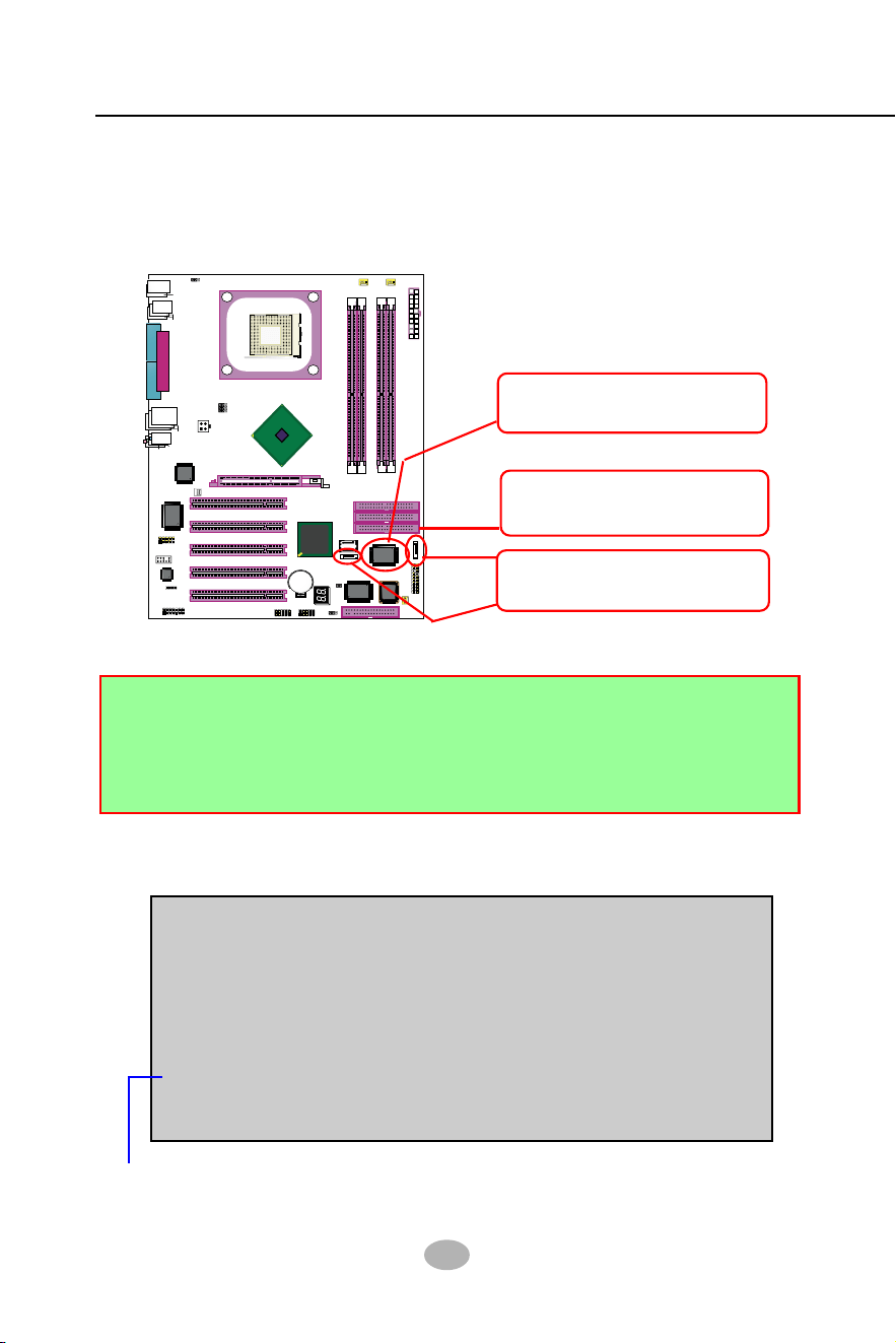
86
SL-865Pro2-FGR
865PE
Intel
Intel 82865PE
BIOS
RTL
ALC655
LPT1
COM1
COM2
mPGA478B
PW1
+12V Power
HDD
IR
PWR
1
20
SPK RST
+
-
+
-
PWLED
LED
Fan1
1
USB3
RJ45
(on top)
AGP1 (8X/4X)
ICH5
Intel
IDE1
IDE2
IDE3
FDC1
PCI1
PCI2
PCI3
PCI4
PCI5
for Dual-channel DDR 400/333/266MHz
Fan
2
PW2
1
JKB1
1
JBAT1
1
JFSB2
JFSB1
PS/2 Mouse
(on top)
PS/2 Keyboard
(
m
id
d
le
)
JAUD1
1
L
i
n
e
i
n
(
o
n
t
o
p
)
L
i
n
e
O
u
t
(
u
n
d
e
r
s
id
e
)
M
i
c
1
CD_IN1
VT6307
VIA
W83627HF
Winbond
USB4
DIMM1 DIMM2
DIMM3 DIMM4
SATA1
SATA2
PDC20378
Promise
1
USB2
USB1(2 ports)
1
IEEE1
10
Fa
n3
IEEE
1394
VIA
VT6122
Li
Battery
JFSB3
ATA1
AUDIO1
Main Power
Fa
n4
(2 ports)
RT3
82801EB
22
1
2
2
2
10
(underside)
LED1
5-1. SATA RAID and PATA RAID Layout on Board
Chipset Promise PDC20378
supporting SATA RAID/PATA
RAID Interfaces
2 SATA connectors (SATA1/
SATA2) supporting 2 SATA
RAID Hard Disks
1 IDE RAID connector (IDE3)
supporting 2 PATA RAID Hard
Disks (supported by PDC20378)
PDC20378 is on board. It supports 2xSATA RAID Disk Drives and
2xPATA (IDE) RAID Disk Drives (and that is why PDC20378 supports
RAID 0+1).
Mainboard SL-865Pro2-FGR
5-3. First Step to Set up RAID - Populate Disk Drives
Following the instruction on the screen, press <Ctrl-F> to enter the
FastBuild (tm) Utility.
At booting system, the following screen will appear after “POST”.
FastTrak 378 (tm) BIOS Version 1.00.1.34
(c) 2002-2005 Promise Technology. Inc. All rights reserved.
No Array is defined...................
Press <Ctrl-F> to enter FastBuild (tm) Utility or
Press <ESC> to continue booting...
1. Connect 1 SATA Disk Drive to ATA1 and 1 SATA Disk Drive to ATA2.
2. Connect 1 or 2 IDE Disk Drives to IDE3.
3. 3 Disk drives can be set up into RAID 0 or 1 Array; 4 for 0+1 mode.
4. Check that in BIOS Setup, the Promise RAID item in “Advanced
BIOS Features” setup should be enabled. RAID cannot be configured.
5-2. To Enter RAID Setup Utility

Chapter 5 RAID & RAID Driver
87
The Main Menu will pop out as below:
FastBuild (tm) Utility 2.01 (c) 2002-2005 Promise Technology, Inc.
Auto Setup..............................[1]
View Drive Assignemnts..........[2]
Define Array............................[3]
Delete Array............................[4]
Rebuild Array..........................[5]
[ Main Menu ]
[ Keys Available ]
Press 1~5 to Select Option [Esc] Exit
5-4. To Enter the Main Menu of FastBuild Utility
1. Auto Setup.........[1]
Press figure “1” on keyboard to enter Auto Setup of RAID.”Auto Setup”
is available only if there are free disk drive detected in system.
2. View Drive Assignment.........[2]
Press figure “2” on keyboard to view the drive assignment detected
in system.
3. Define Array.........[3]
Press figure “3” on keyboard to view the defined Array already set up
in system.
4. Delete Array.........[4]
Press figure “4” on keyboard to enter the “Delete Array” field for
deleting Array already set up in system.
5. Rebuild Array.........[5]
Press figure “5” on keyboard to enter the “Rebuild Array” field for
rebuilding a defective array or RAID member. “Rebuild Array” is
available for “RAID 1 (Mirror)” or “RAIA 0+1 (Mirror/Stripe)” mode.
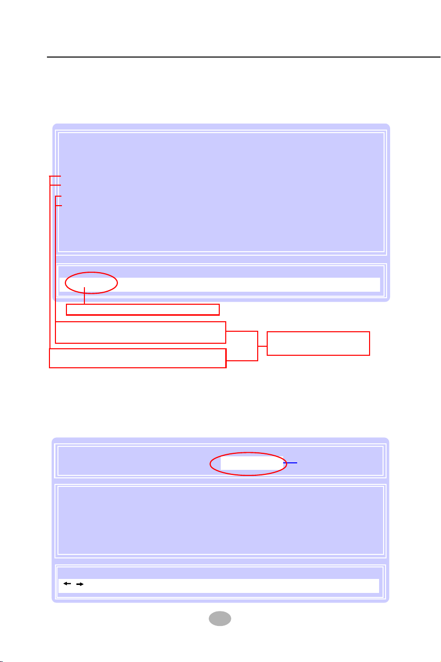
88
SL-865Pro2-FGR
FastBuild (tm) Utility 2.02 (c) 2003-2005 Promise Technology, Inc.
1: Mas ST380023AS 80026 Free U5
2: Mas ST380023AS 80026 Free U5
3: Mas QUANTUM FIREBALLP AS3 30020 Free U2
3: Mas ST330620A 30020 Free U2
[ View Drives Assignments ]
[ Keys Available ]
[Esc] Exit MODE (D = DMA, U = UDMA)
Channel:ID Drive Model Capacity (MB) Assignment Mode
Press “2” to enter “View Drive Assignment” so that you can see the
status of all disk drives detected by RAID BIOS.
Two drives are detected in channel 1 and 2
as free drives (available for RAID setup)
Two drives are detected in channel 3
as free drives (available for RAID setup)
Totally 4 drives are
detected by RAID BIOS
5-5. View Drive Assignment before RAID Setup
On the Main Menu press “1” to enter “Auto Setup” and choose your
RAID mode. If you choose “Performance” and save your choice now,
your RAID is Stripe mode. Since 4 drives are installed, you can also
choose “Security” for your RAID mode.
Press Esc key to return to Main Menu
Mode ................................................Stripe
Spare Drive .......................................0
Drive(s) Used in Array..........................4
Array Disk Capacity (size in MB)..........120080
[ Auto Setup Options Menu ]
Optimize Array for: Performance
[ Array Setup Configuration ]
[ Keys Available ]
Press “ <--- “ key to
change RAID option.
[ , ,Space] Change Option [ESC] Exit [Ctrl-Y] Save
5-6. Enter “Auto Setup” for RAID Setup
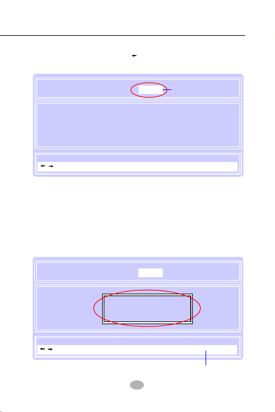
Chapter 5 RAID & RAID Driver
89
Mode ................................................Mirror/Stripe
Spare Drive .......................................0
Drive(s) Used in Array..........................4
Array Disk Capacity (size in MB)..........60000
[ Auto Setup Options Menu ]
Optimize Array for: Security
[ Array Setup Configuration ]
[ Keys Available ]
Do you want to do quick initialize or
create only? (Yes/No)
Y - Create and Quick Initialize
N - Create Only
When a RAID mode is chosen, press < Ctrl-Y> to save the choice.
Then select Y for “Create and Quick Initialize; or select N for “Create
only”.
5-7. Choose “ Security” for RAID 0+1 (Stripe/Mirror)
5-8. Press <Ctrl-Y> to Save the Choice
Security (0+1) mode is
selected.
Mode ................................................Mirror/Stripe
Spare Drive .......................................0
Drive(s) Used in Array..........................4
Array Disk Capacity (size in MB)..........60000
[ Auto Setup Options Menu ]
Optimize Array for: Security
[ Array Setup Configuration ]
[ Keys Available ]
Security (0+1) mode is
selected.
Press <Ctrl-Y> to save choice.
[ , ,Space] Change Option [ESC] Exit [Ctrl-Y] Save
[ , ,Space] Change Option [ESC] Exit [Ctrl-Y] Save
Inside Auto Setup menu Press “ ” key to choose “Security” mode for
your RAID.
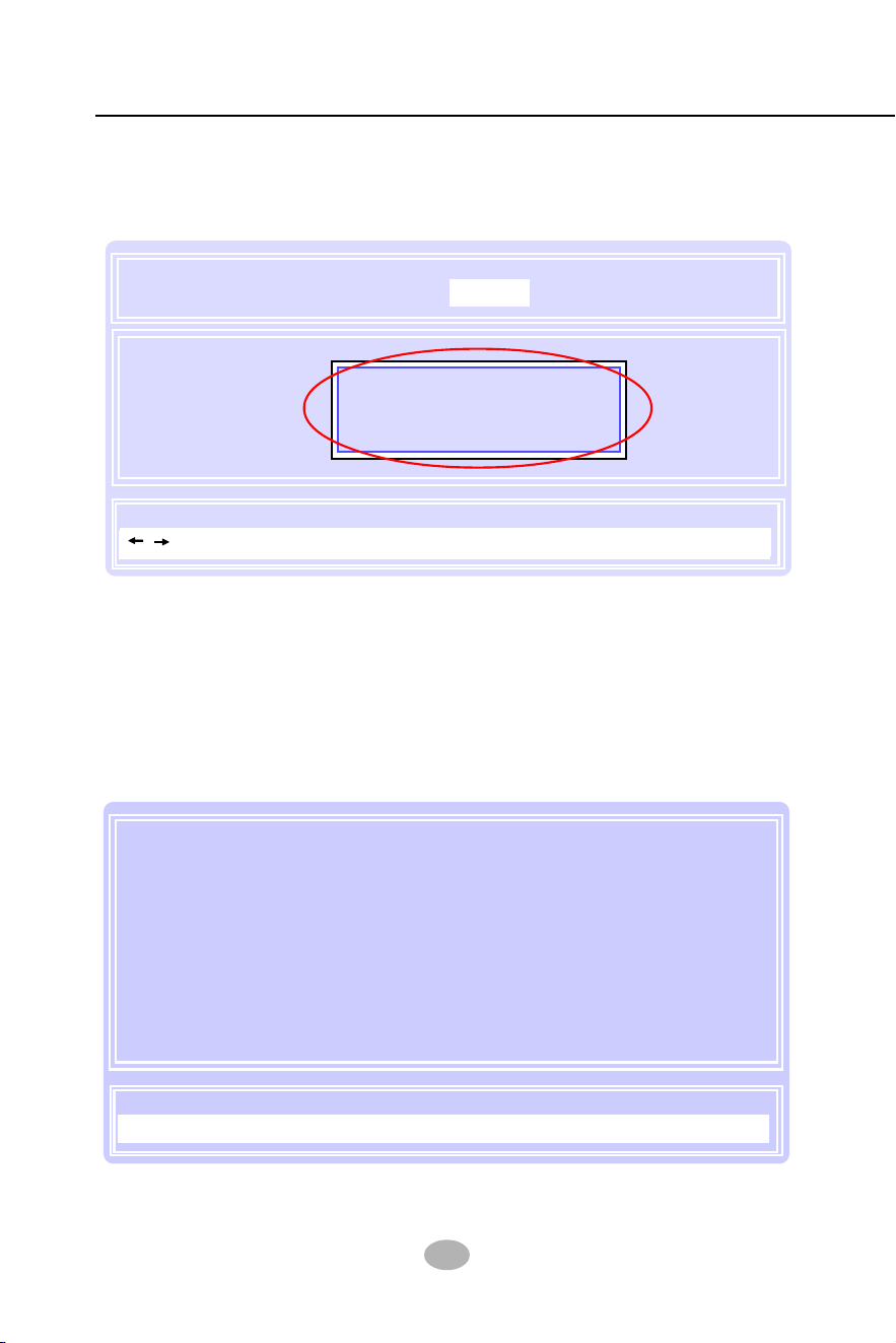
90
SL-865Pro2-FGR
5-10. Array Created and View Drives Assignments
“Create Only” is for creating RAID without changing the disk data.
“Create and Quick Initialize” will create the RAID with clearing disk data.
After choosing “Create Only” or Create and Quick Initialize”, next screen
will return to the Main Menu. You can now press “2” to view drives
assignments. You can see that all drives have already been set to
RAID 1.
5-9. Create RAID Only / Create and Quick Initialize
Mode ................................................Mirror/Stripe
Spare Drive .......................................0
Drive(s) Used in Array..........................4
Array Disk Capacity (size in MB)..........60000
[ Auto Setup Options Menu ]
Optimize Array for: Security
[ Array Setup Configuration ]
[ Keys Available ]
Choose Quick Initialize will delete
any existing data on your hard
disks.
Y - Continue, Others - Cancel
[ , ,Space] Change Option [ESC] Exit [Ctrl-Y] Save
1: Mas ST380023AS 80026 RAID 1 U5
2: Mas ST380023AS 80026 RAID 1 U5
3: Mas QUANTUM FIREBALLP AS3 30020 RAID 1 U2
3: Mas ST330620A 30020 RAID 1 U2
[ View Drives Assignments ]
[ Keys Available ]
[Esc] Exit MODE (D = DMA, U = UDMA)
Channel:ID Drive Model Capacity (MB) Assignment Mode
Chapter 5 RAID & RAID Driver
91
You can also press “3” on the Main Menu to enter the [Define Array}] so
that you can see the RAID mode just set up by yourself.
Congratulation!
Your system is now ready for operating system installation and RAID
Driver Setup.
5-11. Enter [Define Array] to see the RAID Mode
FastBuild (tm) Utility 2.01 (c) 2002-2005 Promise Technology, Inc.
Auto Setup..............................[1]
View Drive Assignemnts..........[2]
Define Array............................[3]
Delete Array............................[4]
Rebuild Array..........................[5]
[ Main Menu ]
[ Keys Available ]
Press 1~5 to Select Option [Esc] Exit
This will EXIT FastBuild!
Are You Sure?
Y - Yes / Any key - Back
FastBuild (tm) Utility 2.02 (c) 2003-2005 Promise Technology, Inc.
Array 1 Mirror/Stripe 4 120080 Functional
Array 2
Array 3
Array 4
Halt On Error : Disable
[ Define Array Menu ]
Array No RAID Mode Total Drv Capacity(MB) Status
5-12. After Array creation, press [Esc] to exit
After Array creation, you can now press “Esc” on the Main Mrenu and
exit RAID setup.

92
SL-865Pro2-FGR
5-13. To Install Promise RAID Driver
Windows Setup
Press F6 if you need to install a third party SCSI or RAID driver....
5-13-1 To Install RAID Driver on Windows 2000/XP/2003
(1) Get ready the Floppy Diskette holding the RAID Driver.
(This Driver Diskette should have been enclosed in the mainboard
Package.)
(2) Check that Hard Disks are connected properly to the RAID conn-
tors.
(3) Start your PC system and use RAID BIOS Setup Utility to configure
RAID 0 / 1/ 0+1 to the hard disks.
(4) Restart System and apply the Windows 2000/XP CD to CD-ROM
for operating system installation.
(5) On the Windows 2000/XP Setup screen, press “F6” key for RAID
driver setup.
Promise RAID Driver is incorporated in Support CD/Floppy Diskette for
user’s installation.
This driver is intended for Windows 98/Me/NT4/2000/
XP/2003.

Chapter 5 RAID & RAID Driver
93
(6) On next screen press “S” to confirm the mass storage device setup.
(7) On next screen apearing, insert the RAID Driver Diskette to Drive
“A” and then press <Enter>.
Windows Setup
S=Specify Additional Device Enter=Continue F3=Exit
Setup could not determine the type of one or more mass storage
devices installed in your system, or you have chosen to manually
specify an adapter. Currently, Setup will load support for the
following mass storage devices(s):
<none>
* To specify additional SCSI adapters, CD-ROM drives, or
special disk controllers for use with Windows, including
those for which you have a device support disk from a
mass storage device manufacturer, press S.
* If you do not have any device support disks from a mass
storage device manufacturer, or do not want to specify
additional mass storage devices for use with Windows,
press ENTER.
Windows Setup
Enter=Continue ESC=Cancel F3=Exit
Please insert the disk labeled
Manufacturer-supplied hardware support disk
into Drive A:
* Press ENTER when ready.
94
SL-865Pro2-FGR
(8) On next screen appearing, choose the driver suitable for your
operating system and press <Enter> to continue.
The Installation Program will then guide you through the rest of system
setup. The RAID driver will then be installed into your system.
Windows Setup
S=Specify Additional Device Enter=Continue F3=Exit
You have chosen to configure a SCSI Adapter for use with Windows,
using a device support disk provided by an adapter manufacturer.
Select the SCSI Adapter you want from the following list, or press
ESC to return to the previous screen.
Win SERVER 2003 Promise FastTrak 376/378 (tm) Controller
WinXP Promise FastTrak 376/378 9tm) Controller
Win2000 Promise FastTrak 376 (tm) Controller
Win2000 Promise FastTrak 378 (tm) Controller
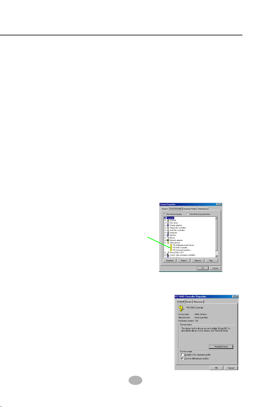
Chapter 5 RAID & RAID Driver
95
(1) Get ready the Floppy Diskette holding the RAID Driver.
(2) Check that Hard Disks are connected properly to the RAID conn-
ectors.
(3) Start your system and use RAID BIOS Setup Utility to configure
RAID 0 / 1/ 0+1 to the hard disks.
The question mark here
indicates that RAID
Controller Driver
is not installed yet.
(8) In the “Device manager” screen, you can see the item “ PCI RAID
Controller” with a yellow question mark on its left side, which indicates
that the RAID controller is already detected by system but the driver
is not installed yet. Please point to this item with your mouse and
double click on it (or click the “Properties” button).
5-13-2 To Install RAID Driver on Windows 98SE/Me
(9) Instantly, the “PCI RAID Controller Properties“ screen shows up.
Please click the “General” bar to continue.
(10) In the “General” screen, click “reinstall
Driver” button to continue. Please note
that the status of “Device Usage”
should stay at “Exists in all hardware
profiles”.
(4) Restart System and format the bootable hard disks.
(5) Now, apply the Windows 98SE/ME CD to CD-ROM for operating
system installation.
(6) With the Windows 98SE/ME installation complete, restart system
for RAID driver setup.
(7) On the “Start” screen of your system, please click to the following
path:
\My Computer\properties\Device manager
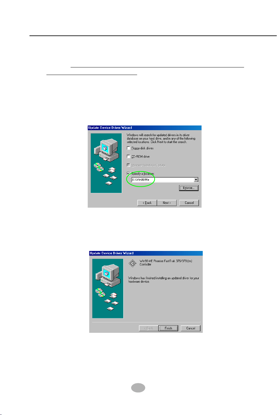
96
SL-865Pro2-FGR
(11) In the “Update device Driver Wizard” screen, click “Next” to continue
until you see a dialog box asking you to “Specify a location” for the
driver. You should now insert the SATA/SATA RAID Driver CD/
Diskette into CD-ROM/Drive A.
(12) As illustrated in the picture below, check the item “Specify a location”
and click the “Browse” button to find out the correct path for the
driver. As the RAID Driver is in Drive A, please type into the blank
bar the correct path and click “Next” to continue:
D:\Driver\Promise\PDC20376&378\Win98-me
or
A:\Win98-me
(13) The Update Device Driver Wizard will then go on installing the
driver. In a few seconds, installation completes. Please click the “Fin-
ish” button on the screen to complete the installation.

Chapter 5 RAID & RAID Driver
97
Memo
Memo
