MODELS:
3VIR09HP115V1AO
3VIR12HP115V1AO
3VIR09HP230V1AO
3VIR12HP230V1AO
3VIR18HP230V1AO
3VIR24HP230V1AO
CAT NO: GREE_VIREOGEN3_INSTALL_090921
Thank you for choosing our product.
Please read this Installation & Owner’s Manual carefully before
operation and retain it for future reference.
If you lose this Manual, please contact your local distributor or
visit www.greecomcomfort.com/resources now to download and
file the electronic version.
INSTALLATION
MANUAL
Single-Zone, Heat Pump System
CONTENTS
Safety precautions
.......................................................................................
1-4
..................................................................................................
....5
.........................................................................................
.6-7
..............................................................................
8-9
.............................................................................................
10
................................................................
11-12
Parts name
Installation notice
Installation of outdoor unit
Test and operation
Configuration of connection pipe
Limited Warranty Statement
................................................................................
13
i
Table of Contents & Quick Tip Video QR Code......................................................i
Explanation of Symbols........................................................................................ii
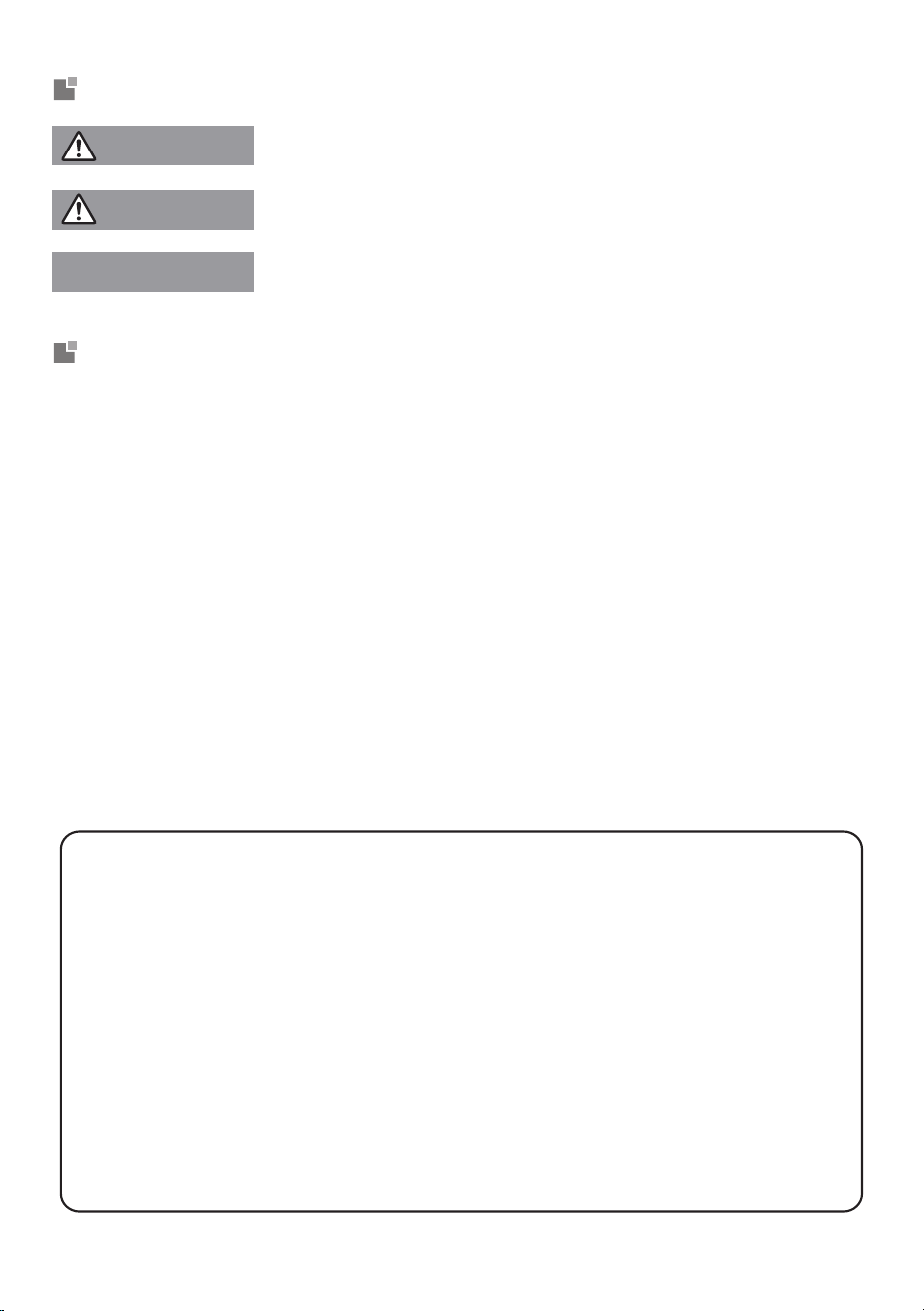
Explanation of Symbols
WARNING
CAUTION
NOTICE
1. Damage the product due to improper use or misuse of the product;
2. Altering, changing, maintaining or using the product with other equipment
without following the recommendations in manufacturer's instruction manual;
3. After verification, the product defect is directly caused by corrosive gas;
4. After verification, the defects are due to improper operation or handling during
the transportation of product;
5. Operating, repairing or maintaining the unit without following the instruction
manual or related regulations.
6. After verification, the problem or dispute is caused by the quality or
performance of parts and components produced by other manufacturers;
7. The damage is caused by natural disasters, a hazardous environment or
force majeure.
Exception Clauses
Manufacturer will bear no responsibilities when personal injury or property loss is
caused by the following reasons.
This symbol indicates the possibility of death or serious injury.
This symbol indicates the possibility of injury or damage to
property.
Indicates important but not hazard-related
information, used
to indicate risk of property damage.
If you need to install, move or maintain this air conditioner, please use a licensed
HVAC dealer to avoid serious damage or personal injury or death.
When refrigerant leaks or requires discharging during installation, maintenance,
or disassembly, it should be handled by certified professionals in compliance
with local laws and regulations.
This equipment is not intended for use by persons (including children) with
reduced physical, sensory or mental capabilities or lack of experience and
knowledge unless they have been given supervision or instruction concerning
use of the equipment by a person responsible for their safety.
Children should be supervised to ensure that they do not play with the
equipment.
ii
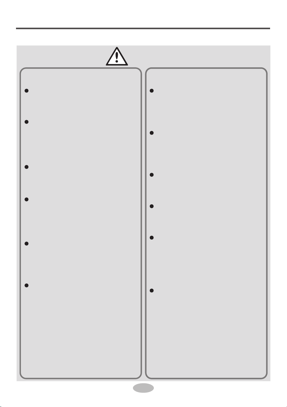
Safety precautions
Installation
1
WARNING
Installation or maintenance
must be performed by qua-
lified professionals.
The equipment shall be
installed in accordance
with local and national
wiring codes.
All wiring, circuit breakers
and disconnects must be
to code.
All wiring of indoor and
outdoor units should be
connected bylicensed
professionals.
Disconnect the power
supply before proceeding
with any work related to
electricity and safety.
All power and control wiring
must conform to the air
conditioner's specification
and local codes. Unstable
power supply or incorrect
wiring may result in
electrical shock ,fire
hazard or unit
malfunction.
Grounding of units must
comply with the National
Electrical Code and local
codes.
Air Conditioner should be
properly grounded. Inco-
rrect grounding may cause
electrical shock.
Do not connect power
before finishing installa-
tion.
To prevent malfunctions,
install a properly sized
circuit breaker.
An all-pole disconnect
switch having a contact
separation of at least 3mm
in all poles should be
installed in fixed wiring.
Circuit breaker must be
properly sized to the unit
specifications and code to
prevent an electrical over-
load or short-circuit.
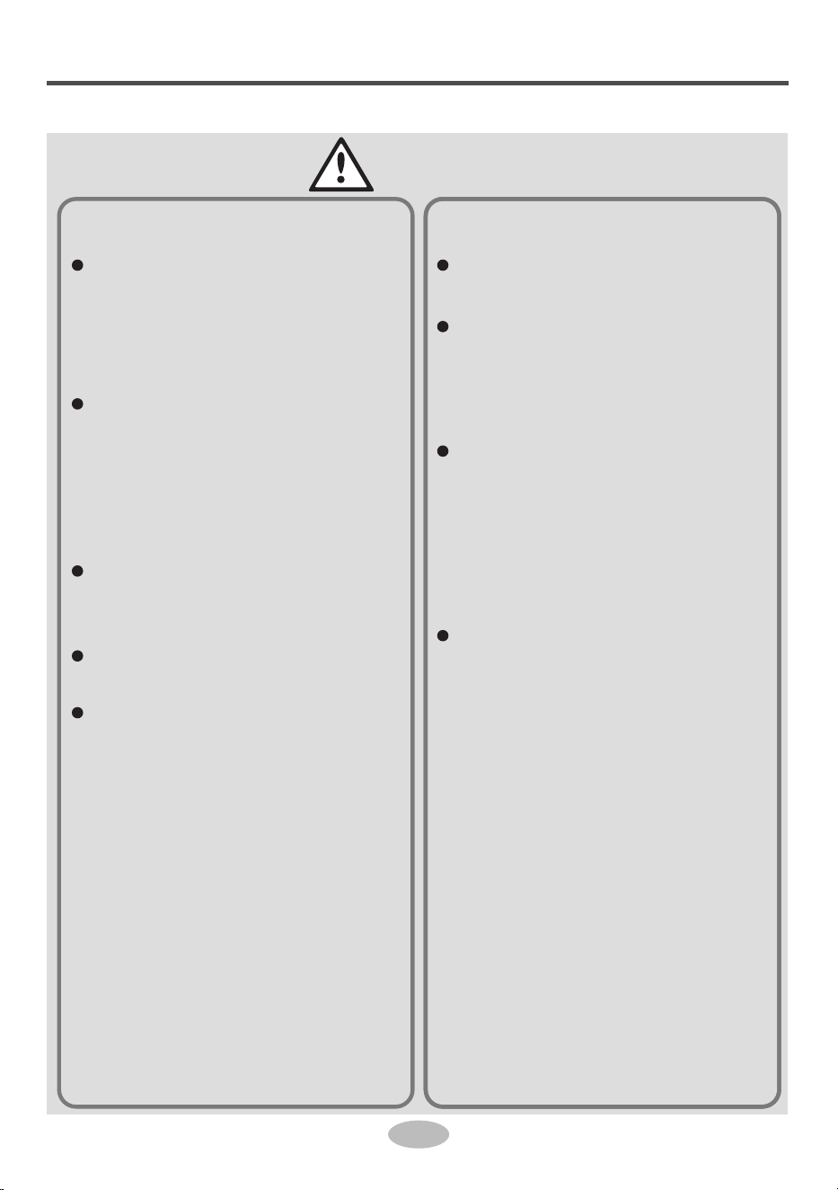
Safety precautions
Installation
2
CAUTION
Instructions for installation
and use of this product are
provided by the manufac-
turer.
Select a location which is
out of reach for children
and far away from animals
or plants. If unavoidable,
please install a fence for
safety.
The indoor unit should be
installed close to an
outside wall.
Wire to code (see
submittals).
Power and control wiring
from the outdoor unit to
the indoor unit must be
continuous.
A circuit breaker must be
installed in the line.
The yellow-green wire is
the ground wire it cannot
be used for any other
purpose.
This air conditioner is a
first class electric equip-
ment. It must be properly
grounded to code.
Improper grounding could
cause an electrical shock.
The refrigerant circuit
temperature will be hot,
keep the interconnecting
wire away from all copper
tubing.
Safety precautions
Operation
and Maintenance
3
WARNING
This equipment can be
used by children aged
from 8 years and above
and persons with reduced
physical, sensory, or
mental capabilities or
lack of experience and
knowledge if they have
been given supervision or
instruction concerning use
of the equipment in a
safe way and understand
the hazards involved.
Children shall not play with
the equipment.
Cleaning and user main-
tenance shall not be made
by children without super-
vision.
If the supply wiring is
damaged, it must be
replaced by a licensed
HVAC technician or other
licensed electrical
professional.
Connect air conditioner
to a dedicated circuit
breaker.
Disconnect power supply
when cleaning air condit-
ioner, to avoid an
electrical shock.
To avoid electrical shock,
do not wash the
equipment with water.
To avoid electrical shock
or unit malfunction do not
spray water on indoor unit.
Do not repair air condition-
er by yourself. Doing so
may cause electrical shock
or damage. Contact a
licensed HVAC
contractor.
To avoid injury, do not
touch fins when removing
the filter.
Do not extend fingers or
objects into air inlet or air
outlet. It may cause
personal injury or damage.
Safety precautions
Operation
and Maintenance
4
CAUTION
To avoid damaging the
remote controller, do not
spill water on it.
To avoid damage when
drying the air filter, do not
use a flame or hair dryer.
Do not block air outlet or
air inlet. It may cause the
unit to malfunction.
Do not step on or put heavy
objects on top panel of
outdoor unit . It may
damage the unit or cause
personal injury.
If any of the following
occur, turn off the air
conditioner and disconnect
power immediately and
contact the dealer or a
qualified professional for
service.
Wiring is overheating or
damaged.
Abnormal sounds
during operation.
Circuit breaker trips off
frequently.
A burning smell coming
from the air conditioner.
Indoor unit is leaking.
5
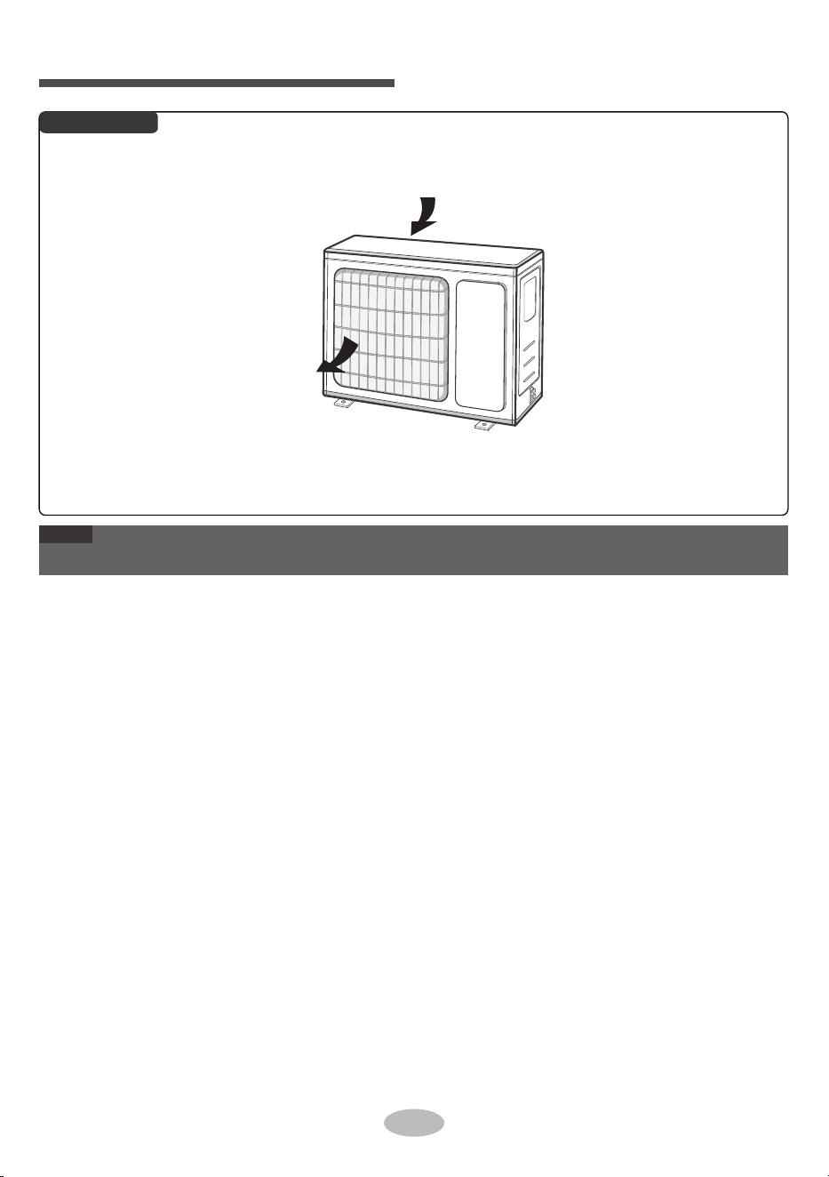
Parts name
Outdoor Unit
●
Actual product may be different from above graphics, please refer to actual product.
air inlet
air outlet
NOTE
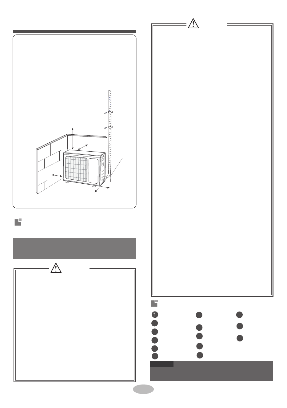
Installation notice
Drainage pipe
Space to the obstruction
At least 20 in
Space to the obstruction
At least 12 in
Space to the obstruction
At least
20 in
Space to the obstruction
At least 78 in
Space to the wall
At least 12 in
6
■
■
■
■
■
7
■
To ensure safety, please be mindful of the
following precautions.
■
12
2
8
13
3
9
4
5
14
10
6
11
■
WARNING
Please contac t the local agent for installation.
Don’t use unqualified power cold.
WARNING
Tools for installation
Screw driver
Impact drill
Open-end
Pipe cutter
wrench
detector
Leak
Vacuum pump
Level meter
Pressure meter
Universal
meter
Measuring
tape
spanner
Inner hexagon
When installing or relocating the unit, be
s
ure to keep the refrigerant
circuit free
from
air or substances other than the
specified
refrigerant.
Any presence of air or other foreign
substance in the refrigerant circuit will cause
system pre-ss
ure rise or comp
ressor
rupture,
resulting in injury.
When installing or moving this unit, do
not charge the refrigerant which is not
comply with that on the nameplate or
unqualified refrigerant.
Otherwise, it may cause abnormal operation,
wrong action, mechanical malfunction or even
serious safety accident.
When refrigerant needs to be recovered
during relocating or repairing the unit,be
sure that the unit is running in cooling mode.
Then, fully close the valve at high pressure
side (liquid valve). About 30-40 seconds later,
fully close the valve at low pressure side
(gas valve), immediately stop the unit and
disconnect power. Please note that the time
for refrigerant recovery should not exceed
1 minute.
Drill head
Pipe expander
●
●
Torque wrench
When installing the unit, make sure that
connection pipe is securely connected
before the compressor starts running.
If compressor starts running when stop valve
is open and connection pipe is not yet conne-
cted, air will be sucked in and cause pressure
rise or compressor rupture, resulting in injury.
Prohibit installing the unit at the place where
there may be leaked corrosive gas or flamm-
able gas.
If there is leaked gas around the unit, it may
cause an explosion and other accidents.
Do not use extension cords for electrical co-
nnections. If the electric wire is not long eno-
ugh, please contact a local service center au-
thorized and ask for a proper electric wire.
Poor connections may lead to electric shock or fire.
Use the specified types of wires for electrical
connections between the indoor and outdoor
units. Firmly clamp the wires so that their te-
rminals receive no external stresses.
Electric wires with insufficient capacity, wrong
wire connections and insecure wire terminals
may cause electric shock or fire.
If refrigerant recovery takes too much time,
air may be sucked in and cause pressure
rise or compressor rupture, resulting in injury.
During refrigerant recovery, make sure that
liquid valve and gas valve are fully closed
and power is disconnected before detachi-
ng the connection pipe.
If compressor starts running when stop valve
is open and connection pipe is not yet conn-
ected, air will be sucked in and cause pressure
rise or compressor rupture, resulting in injury.
Safety precautions for installing and
relocating the unit
NOTICE
8.
2.
Selection of installation location
Requirements for electric connection
Basic requirement
Installing the unit in the following places may cau-
se malfunction. If it is unavoidable, please consu-
lt the local dealer:
3.
4.
5.
6.
7.
It’s not allowed to be installed on
the unstable
or motive base structure
(such as truck) or in
the corrosive environ
ment (such as chemical
factory).
The place near coast area.
The place with oil or fumes in the air.
The place with sulfureted gas.
Other places with special circumstances.
The equipment shall not be installed in the
laundry.
flammable or explosive gas, or volatile objects
spread in the air.
1.
The place with strong hea t sources, vapors,
The place with high-frequen cy devices (such
as welding machine, medical equipment).
8.The temperature of refrigerant circuit will be hi-
gh, please keep the interconnection cable away
from the copper tube.
with national wiring regulations.
9.The equipment shall be installed in accordance
7
6.Do not put through the power before finishing
installation.
4.
7.
If the supply cord is damaged, it must
be repla-
3.
ced by the manufacturer, its
service agent or
similarly qualified
persons in order to avoid a
hazard .
Properly connect the live wire, neutral wire and
grounding wire of power socket.
Make sure the power supply matches with the
requirement of air conditioner.
Unstable power
supply or incorrect wiring or malfunction. Pl-
ease install proper power supply cables before
using the air
conditioner.
5.
Be sure to cut off the power supply
before pr-
oceeding any work related to
electricity and safety.
Outdoor unit
1.Select a location where the noise and outflow
3.
neighborhood.
2.
The location should be well ventilated and dry,
in which the outdoor unit won't be exposed dir-
ectly to sunlight or strong wind.
The location should be able to withstand the
Select a location which is out of reach for chil-
air emitted by the outdoor unit will not affect
5.
dren and far away from animals or plants. If it
is unavoidable, please add the fence for safety
purpose.
uirement of installation dimension diagram.
weight of outdoor unit.
4.
Make sure that the installation follows the req-
Safety precaution
1.
2.
Must follow the electric safety regulations w-
hen installing the unit.
According to the local safety regulations, use
qualified power supply circuit and air switch.
4.
5.
2.
3.
The yellow-green wire in air conditioner is
grounding wire, which can 't be used for other
purposes.
Grounding requirement
The grounding resistance should comply with
national electric safety regulations.
T
h
e equipment must be positioned so that the
disconnect is accessible.
An all-pole disconnection switch having a co-
ntact separation of at least 3mm in all poles
should be connected in fixed wiring.
1.
T
he air conditioner is the first class
electric
equipment. It must be properly grounded with
specialized grounding
device by a professional.
Please make
sure it is always grounded effecti-
vely, otherwise it may cause electric shock.
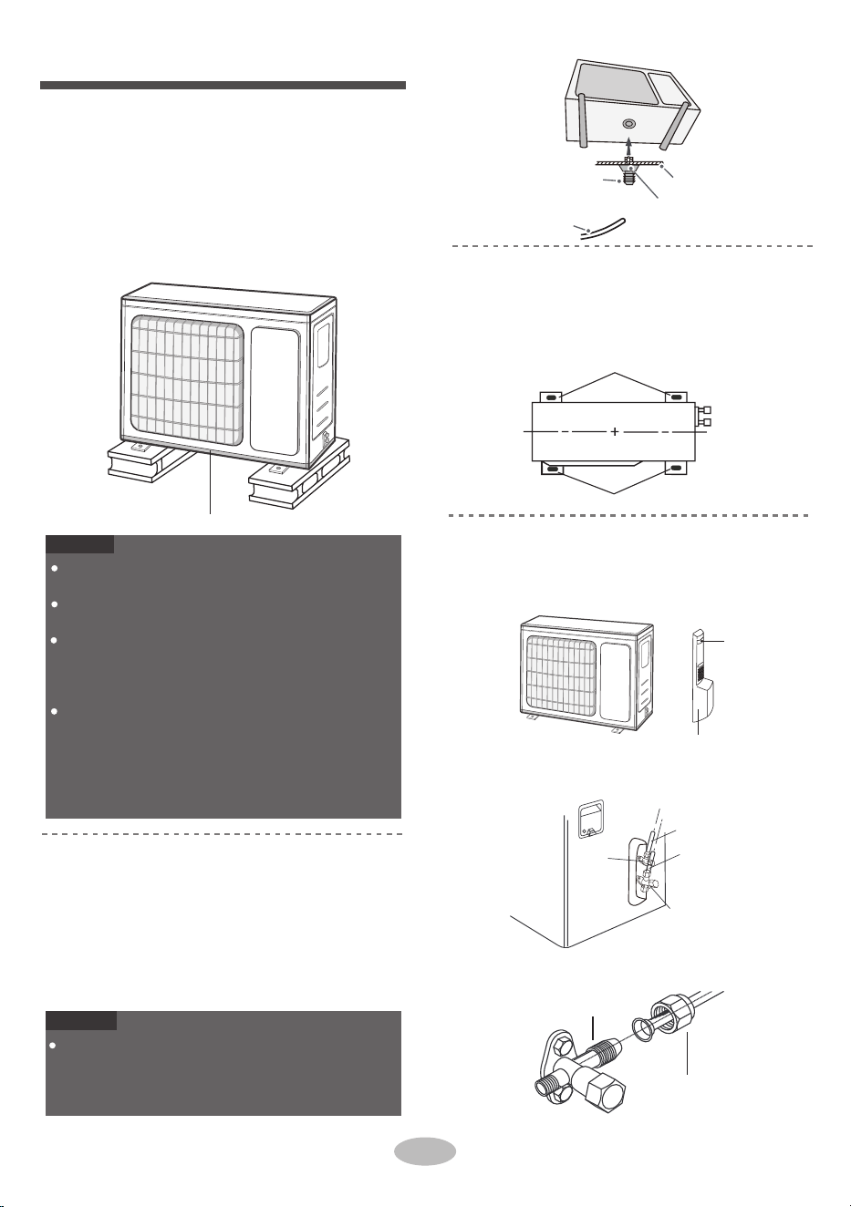
Installation of outdoor unit
drain vent
Drain hose
Place the outdoor unit on the support.
2. Fix the foot holes of outdoor unit with bolts.
foot holes
foot holes
at least 3cm above the floor
1. Remove the screw on the right handle of out-
handle
Remove the screw cap of valve and aim the
pipe joint at the bellmouth of pipe.
2.
gas valve
3.
2.
union nut
Step 1:
Fix the support of outdoor unit
(select it according to the actual inst-
2.
chassis
outdoor drain joint
NOTICE
Take sufficient protective measures when installin g
the outdoor unit.
Make sure the support can withstand at least fou r
times of the unit weight.
The outdoor unit should be installed at least
1-1/4 in above the floor in order to install drain
joint.(for the model with heating tube, the
installation height should be no less than 8 in.)
For the unit with cooling capacity of 9000 -
12000 Btu,
6 expansion screws are needed ; for
the unit with cooling capacity of 24000~30000
Btu,
8 expansion screws are needed; for the unit
with cooling capacity
of 36000+ Btu 10
expansion screws are needed.
Step 4:
Connect indoor and outdoor pipes
door unit and then remove the handle.
screw
liquid pipe
gas pipe
Step 2:
Install drain joint
(only for some models)
1.
liquid
valve
Connect the outdoor drain joint into the hole
on the chassis, as shown in the picture below.
Connect the drain hose into the drain vent.
NOTICE
As for the shape of drainage joint, please refer
to the current product. Do not install the drainage
joint in the severe cold area. Otherwise,it will be
frosted and then cause malfunction.
allation situation)
1.
Select installation location according to
Step 3:
Fix outdoor unit
1.
Pretighten the union nut with hand.
pipe joint
the house structure.
Fix the support of outdoor unit on the sele-
cted location with expansion screws.
8
4.
2.
1.
The water outlet can't be placed in water in
order to drain smoothly.
The drain hose can't be fluctuant
2.
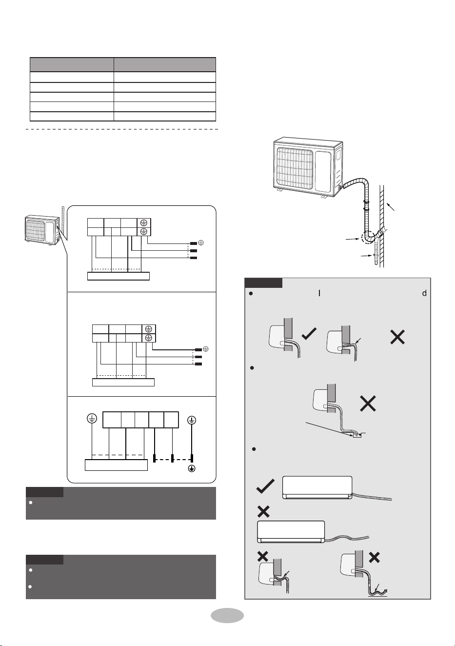
Step 5:
Connect outdoor electric wire
wall
U-shaped curve
drain hose
the drain hose
can't raise
upwards.
The water outlet
can't be placed
in water
The wiring board is for reference only, please refer
to the actual one.
The drain hose
After tighten the screw, pull the power cord slightly
to check if it is firm.
Never cut the power connection wire to prolong or
shorten the distance.
can't be fluctuant
The water
outlet can't be
fluctuant
Step 6: Pipe Neatly
Remove the wire clip; connect the power con-
nection wire and signal control wire (only for
cooling and heating unit) to the wiring terminal
according to the color; fix them with screws.
9
Fix the power connection wire and signal con-
trol wire with wire clip (only for cooling and h-
eating unit).
1.
Slant the drain hose slightly downwards.
The drain hose can't be curved, raised and
fluctuant, etc.
The through-wal height of drain hose shoul
not be higher than the outlet pipe hole of in-
door unit.
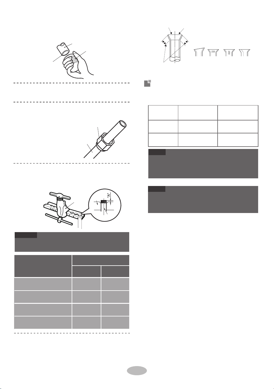
Tighten the union nu t with torque wrench
by referring to the sheet below.
15~20
30~40
45~55
60~65
70~75
1/4''
3/8''
1/2''
5/8''
3/4''
NOTICE
NOTICE
Hex nut diameter
Tightening torque(N m)
.
NOTICE
reasonably and hidden possibly. Min. semidiam-
eter of bending the pipe is 4 in.
The pipes should be placed along the wall, bent
L1 L2
black
Indoor unit connection
black(brown)
green
(yellow-green)
white
(blue)
L2
L1
green(yellow-green)
POWER
white
(blue)
red
(brown)
N(1) 2 3
09K、K21
N L
black
Indoor unit connection
black(brown)
green
If the outdoor unit is higher than the wall hole,
you must set a U-shaped curve in the pipe
before pipe goes into the room, in order to
prevent rain from getting into the room.
(yellow-green)
white
(blue)
L
N
green(yellow-green)
POWER
white
(blue)
red
(brown)
2N(1) 3
:
3VIR09HP115V1AO
3VIR12HP115V1AO
white
black
red
L1 L2
Indoor unit connection
POWER
(blue)
(brown)
white
(blue)
N(1) 2 3
black
(brown)
L1 L2
green
green)
(yellow-
green
green)
(yellow-
18K、24K:
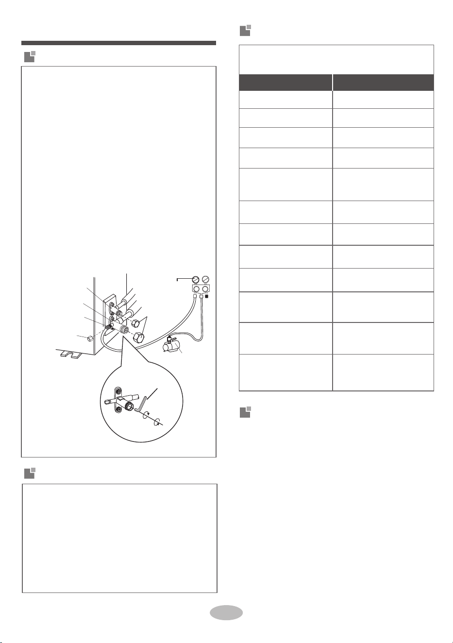
Test and operation
6. Tighten the screw caps of valves and refriger-
ant charging vent.
Leak detection
Use vacuum pump
Remove the valve caps on the liquid valve and
1.
1.
2.
Reinstall the handle.7.
of liquid valve and gas valve completely with
inner hexagon spanner.
gauges
valve cap
Lo Hi
liquid valve
gas valve
refrigerant charging
vent
nut of refrigerant
charging vent
close
open
vacuum pump
inner hexagon
spanner
for 10-15 min to check if the pressure gauge
remains in -15 psi.
4. Close the vacuum pump and maintain this sta-
tus for 1-2min to check if the pressure of
gauge remains in -15 psi. If the pressure de-
creases, there may be a leak.
5. Remove thegauges, open the valve core
10
3.
Open the gauges completely and operate
refrigerant charging vent of gas valve and then
connect the other charging hose to the vacuum
pump.
With a leak detector:
Check if there is a leak.
With soap water:
If leak detector is not available, please use
soapy water for leak detection. Apply soap
water at the suspected position and keep the
soap water for more than 3min. If there are air
bubbles coming out of this position, there's a
leak.
gas valve and the nut of refrigerant charging vent.
2.
Connect the charging hose of gauges to the
Check after installation
Test operation
●
1.
●
●
Check according to the following requirement
after finishing installation.
Preparation of test operation
The client approves the air conditioner.
Specify the important notes for air conditioner to
the client.
Items to be checked Possible malfunction
The unit may drop, shake or
emit noise.
Has the unit been
installed firmly?
Is water drained well?
It may cause condensation
and water dripping.
Have you done the refri-
gerant leak test?
It may cause insufficient
cooling(heating) capacity.
It may cause malfunction or
damage the parts.
Is electric wiring and pip-
eline installed correctly?
It may cause malfunction or
damage the parts.
Is the unit grounded
securely?
Does the power cord fol-
low the specification?
It may cause malfunction or
damage the parts.
Is there any obstruction in
the air inlet and outlet?
Is heat insulation of pipe-
line sufficient?
It may cause malfunction or
damage the parts.
The gas valve and liquid
valve of connection pipe
are open completely?
The dust and sundries
caused during installation
are removed?
It may cause condensation
and water dripping.
It may cause electric leakage.
Is the inlet and outlet of
piping hole been covered?
Is the voltage of power
supply according to the
voltage marked on the
nameplate?
It may cause insufficient
cooling(heating) capacity.
It may cause insufficient
cooling (heating) capacity.
It may cause insufficient
cooling (heating) capacity
or waste electricity.
●
●
2.
●
Method of test operation
no nottub FFO/NO sserp ,rewop eht hguorht tuP
the remote controller to start operation.
Press MODE button to select AUTO, COOL, DRY ,
FAN and HEAT to check whether the operation is
normal or not.
If the ambient temperature is lower than 16°C(61°F),
the
air conditioner can’t start cooling.
1.
50
Max. length of
connection pipe(ft)
66
82
82
9000Btu/h (2637W)
12000Btu/h (3516W)
18000Btu/h (5274W)
24000Btu/h (7032W)
Cooling capacity
Max. length of connection pipe
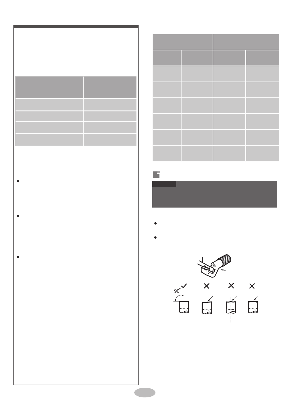
Pipe expanding method
pipe cutter
pipe
Configuration of connection pipe
A: Cut the pipe
2.
3.
leaning
uneven burr
Standard length of connection pipe: 5m, 7.5m,
8m.
Min. length of connection pipe is 3m.
Max. length of connection pipe is shown as below.
4.
The additional refrigerant oil and refrigerant charg-
ing required after prolonging connection pipe.
After the length of connection pipe is prolonged
for 10m at the basis of standard length, you should
add 5ml of refrigerant oil for each additional 5m
of connection pipe.
The calculation method of additional refrigerant
charging amount(on the basis of liquid pipe):
Additional refrigerant charging amount =
prolonged length of liquid pipe × additional
refrigerant charging amount per meter
Basing on the length of standard pipe, add re-
frigerant according to the requirement as shown
in the table. The additional refrigerant charging
amount per meter is different according to the
diameter of liquid pipe. See the following sheet.
Confirm the pipe length according to the distance
of indoor unit and outdoor unit.
Cut the required pipe with pipe cutter.
NOTICE
Improper pipe expanding is the main cause of refriger-
ant leaks. Please expand the pipe according to the
following steps:
11
Outdoor unit throttle
Liquid pipe Gas pipe
1/4''
3/8'' or 1/2''
.215
1/4'' or 3/8''
5/8'' or 3/4''
.54
1/2''
3/4'' or 7/8''
1.29
5/8''
1'' or 1 1/4''
1.29
3/4''
_
2.7
7/8''
_
3.76
Clg and
htg (oz/ft)
Additional refrigerant charging amount for
R410A
Piping size
smooth surface
improper expanding
shaper
downwards
the length is equal
leaning
damaged
crack
surface
C: Put on suitable insulating pipe
union pipe
pipe
expander
pipe
26.7/-(80/-)
A(mm)
Max Min
1.3 0.7
1.6 1.0
●
The operating temperature range (outdoor temper-
"A" is different according to the diameter, please refer
to the sheet below:
1.8 1.0
Expand the port with expander.
2.4 2.2
12
uneven
thickness
Working temperature range
hard
mold
Maximum
cooling
DB/WB
(°C /°F)
26.7/19.4
(80/67)
50/24
(122/75)
Outdoor side
NOTICE
●
Maximum
heating
NOTE
●
30/18
(86/65)
Outer diameter
(mm)
The operating temperature range (outdoor temper-
ature) for cooling is -29°C(-20°F)~50°C(122°F); for
heating is -30°C(-22°F)~30°C(86°F).
3VIR09HP230V1AO, 3VIR12HP230V1AO
3VIR18HP230V1AO, 3VIR24HP230V1AO
ature) for cooling is -25°C(-13°F)~50°C(122°F); for
heating is -30°C(-22°F)~30°C(86°F).
Φ6 - 6.35(1/4")
Φ9 - 9.52(3/8")
Φ12-12.7(1/2")
Φ15.8-16(5/8")
DB/WB
(°C /°F)
Indoor side
B: Remove the burrs
●
Remove the burrs with shaper and prevent the
D: Put on the union nut
pipe and outdoor valve;
install the union nut on
the pipe.
●
E: Expand the port
●
Remove the union nut on the indoor connection
Check the quality of expanding port. If there is
F: Inspection
●
3VIR09HP115V1AO,3VIR12HP115V1AO
NOTE
burrs from getting into the pipe.
pipe
any blemish, expand the port again according to
the steps above.
LIVV12HP230V1A
LIVV24HP230V1A
LIVV36HP230V1A
66129937224
LIMITED WARRANTY STATEMENT
FOR WARRANTY SERVICE OR REPAIR:
Contact your installing contractor. You may find the installer’s name on the equipment or in your Owner’s packet. Complete product registration below and
keep on file for future reference. Warranty registration: Register your unit(s) on www.greecomfort.com, follow links to "Warranty
Registration"
GREE distributor (hereinafter “Company”) warrants this product against failure due to defect in materials or workmanship under normal use and maintenance
as follows. All warranty periods begin on the date of original installation. If the date cannot be verified, the warranty period begins one hundred twenty (120)
days from
date of manufacture. If a part fails due to defect during the applicable warranty period, Company will provide a new or remanufactured part, at
Company’s option, to replace the failed defective part at no charge for the part. This limited warranty is subject to all provisions, conditions, limitations and
exclusions listed below.
• A warranty period of Five (5) years on all parts to the original registered end user.
• A warranty period of 90 days on the remote control provided with the original unit.
• A warranty period of 1 yr on all parts to the original registered commercial end user.
Limited warranty applies only to systems that are properly installed by a state certified or licensed HVAC contractor, under applicable local and state
law in accordance with all applicable building codes and permits; GREE installation and operation instructions and good trade practices.
• Warranty applies only to products remaining in their original installation location.
• Defective parts must be returned to the distributor through a registered servicing dealer for credit.
LIMITATIONS OF WARRANTIES:
ALL IMPLIED WARRANTIES AND/OR CONDITIONS (INCLUDING IMPLIED WARRANTIES OR CONDITIONS OF
MERCHANTABILITY
AND FITNESS FOR A PARTICULAR USE OR PURPOSE) ARE LIMITED TO THE DURATION OF THIS LIMITED WARRANTY, SOME STATES OR
PROVINCES DO NOT ALLOW
LIMITATIONS ON HOW LONG AN IMPLIED WARRANTY OR CONDITION LASTS, SO THE ABOVE MAY NOT APPLY TO YOU. THE
EXPRESS WARRANTIES MADE IN THIS
WARRANTY ARE EXCLUSIVE AND MAY NOT BE ALTERED, ENLARGED, OR CHANGED BY ANY DISTRIBUTOR, DEALER, OR
OTHER PERSON, WHATSOEVER.
THIS WARRANTY DOES NOT COVER:
1.
Labor or other costs incurred for diagnosing, repairing, removing, installing, shipping, servicing or handling of either defective parts, or replacement parts, or new
units.
2. Product cleaning required prior to warranty service and repair.
3. Normal maintenance as outlined in the installation and servicing instructions or Owner’s Manual, including filter cleaning and/or replacement and lubrication.
4. Failure, damage or repairs due to faulty installation, misapplication, abuse, improper servicing, unauthorized alteration or improper operation.
5. Failure to start due to voltage conditions, blown fuses, open circuit breakers, or damages due to the inadequacy or interruption of electrical service.
6. Failure or damage due to floods, winds, fires, lightning, accidents, corrosive environments (rust, etc.) or other conditions beyond the control of the Company.
7. Failure or damage of coils or piping due to corrosion on installations within one (1) miles of sea coast or corrosive body.
8. Parts not supplied or designated by Company, or damages resulting from their use.
9. Products installed outside the 48 contiguous United States, except the District of Columbia and Hawaii.
10. Electricity or fuel costs, or increases in electricity or fuel costs from any reason whatsoever, including additional or unusual use of supplemental electric heat.
11. Any cost to replace, refill or dispose of refrigerant, including the cost of refrigerant.
12. Shipping damage or damage as a result of transporting the unit.
13. Accessories such as condensate pumps, line sets and so forth are not covered.
14. Any special, indirect or consequential property or commercial damage of any nature whatsoever. Some states or provinces do not allow the exclusion of
incidental
or consequential damages, so the above limitation may not apply to you.
15. Consumable components, such as air filters, are not covered under parts warranty.
This warranty gives you specific legal rights, and you may also have other rights which vary from state to state. In jurisdictions where
warranty benefits conditioned on registration are prohibited by law, registration is not required, and the STANDARD warranty period
shown above will apply.
WSO003102021 DLSWARR-HP
PRODUCT REGISTRATION
Model No.
Serial No. Date of Installation
Owner Name
Address of Installation
Installing Contractor
Address
Phone No. / E-mail

CAT NO: GREE_VIREOGEN3_INSTALL_090921
U.S. CONTACT INFORMATION TRADEWINDS, LLC
E-mail:
info@twclimate.com
Contractor Support: 888-850-7928 | Mon-Fri 8 AM - 5 PM EDT
GRE E C O M F O R T . C O M