Visit Our Website
SCAN ME
PyleUSA.com
USER GUIDE
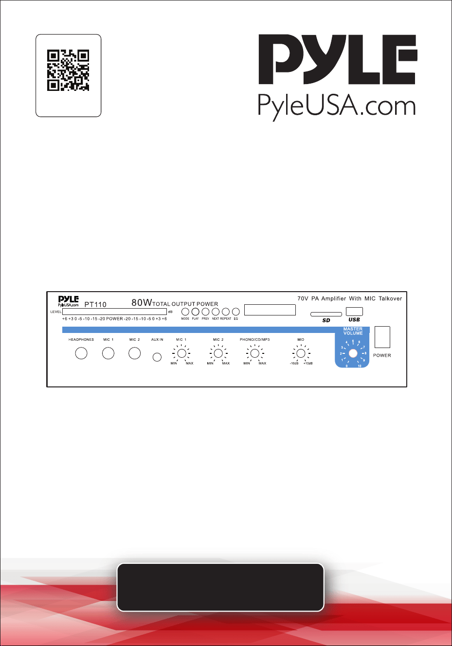
PT110
80 Watt AC/DC Microphone PA Mono Amplifier
with USB/SD/Bluetooth

www.PyleUSA.com
2
Please take the time to read this manual carefully before you begin using
your new device. Any revisions to the manual will not be announced, and we
are not responsible for any consequences caused by misuse or oversight of
this manual.
TABLE OF CONTENTS
FEATURES AND TECHNICAL SPECS
INTRODUCTION
FEATURES AND CONTROLS
STEPS FOR CONNECTING WITH WIRELESS BT DEVICE
INSTALLATION GUIDELINES
USING HEADPHONES
CONNECTING TO STANDARD AC POWER
CONNECTING TO 4A/12V DC POWER
TURNING THE AMPLIFIER ON
USING THE MASTER VOLUME CONTROL
USING THE MIX BUS JACK
REMOTE CONTROL
MAINTENANCE GUIDE
STORAGE GUIDE
REGISTER PRODUCT
3
4
4
5
6
12
12
12
12
13
13
14
15
15
15

www.PyleUSA.com
3
FEATURES:
• 1/4'' Phone Jack
• LED Level Display
• Master Volume Control
• Tone Control
• Mix Bus Jacks
• Front 3.5mm AUX CD Input Jack
• MIC 1/MIC 2 Talkover
• DC 12V Inlet
• Phono/Aux Volume Control
• Mic 1 Mic 2 Volume Controls
• Mic 1 Mic 2 6.35mm Connectors
• Removable AC Cord
• Unswitched AC Outlet
• Phono/Aux/RCA Input Jacks
• Phono/Aux Input Selector
• Variety of Speaker Outputs Terminal
• USB/SD/FM/ LED Display & Bluetooth Features
• Includes Bluetooth Antenna to Improve Bluetooth Distance
• Includes FM Antenna to Improve FM Sensitivity
BLUETOOTH WIRELESS CONNECTIVITY:
• Simple & Hassle-Free Pairing Ability
• Works with All of Today’s Latest Devices (Smartphones, Tablets, Laptops, Computers, etc.)
• Bluetooth Network Name: ‘PYLEUSA’
• Bluetooth Version: 5.0
• Wireless Range: 40’ + ft.
WHAT'S IN THE BOX:
• PA Microphone Mono Amplier • Remote Control
TECHNICAL SPECS:
• Power Supply: 80 Watt
• Power Output: 70V
• Voltage Selector: 120/240V
• Construction Material: Iron
• Frequency Response: 50Hz - 20kHz
• Battery Operated Remote, Requires (1) x CR-2025 Button Cell Battery, Included
• Impedance: 4 Ohm, 8 Ohm, 10 Ohm, 70V
• Product Dimension (L x W x H): 12.6’’ x 10’’ x 3.75’’ -inches
www.PyleUSA.com
4
INTRODUCTION
Your new PYLE PT110 PA AMPLIFIER gives you the power and versatility you need
in a professional sound system. The amplier's wide frequency response makes it
suitable for amplifying music or vocal program material. It can be used for live bands,
oce paging systems, public announcements, or a variety of other installations.
Please read this manual thoroughly before you attempt to set up and use the
amplier. It contains a range of installation suggestions as well as instructions to
ensure safe usage. When installed properly, you can expect years of trouble-free
service from this product.
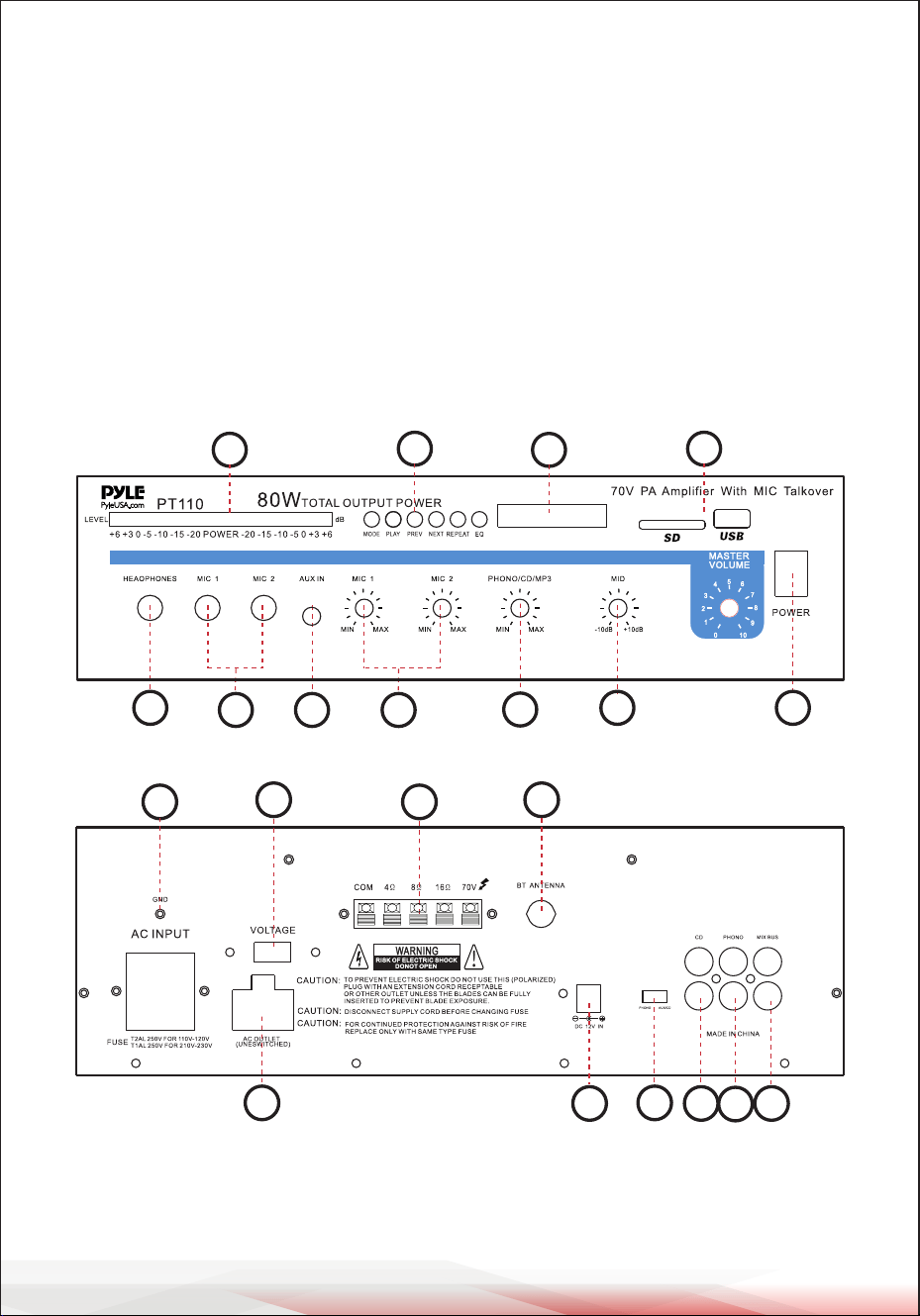
FEATURES AND CONTROLS
FRONT PANEL
REAR PANEL
1. POWER SWITCH: Press to turn the unit ON or OFF.
2. Phone Jack: Connect a pair of stereo headphones for private listening or cueing
(monitoring) sound prior to airing it.
12
4
3 8 5
6
7
9
10
11
15
1816
17
21
14
12
13
20
19

www.PyleUSA.com
5
3. MIC 1 & MIC 2 Jacks: Allow you to connect up to two 6.35mm microphones.
4. LED Level Display Meter
5. MIC Volume Control: Lets you adjust the MIC1/MIC2 sound level.
6. Three Input Sources Mixing Controls: Control the sound level for each of the
audio input sources.
PHONO/AUX: Select and connect an alternative high-level (AUX/CD) or low-level
(PHONO) audio sound source.
7. 100 Hz, 1 kHz, & 8 kHz Equalizer Controls: To enhance the sound or tailor the
high, midrange, and low frequencies for each audio source input to the acoustics
of a particular performance environment, you can adjust these equalizer tone
controls.
8. AUX Input Jack: Allows you to connect any high-level sound source, such as a
CD player, tape deck, or tuner, to the AUX input.
9. CONTROL PANEL BUTTONS:
A. These buttons are only used to control the USB/SD, and Bluetooth functions
and do not control other functions.
B. MODE BUTTON: Press this button to select one of the following modes:
USB/SD or Bluetooth play. USB/SD mode will be set automatically after turning
ON the unit. It automatically plays MP3 les after inserting a USB ash drive or SD
card. You cannot select AUX, CD, and DVD inputs using this button.
C. Each press of the PLAY/PAUSE BUTTON toggles the operation from play to
pause or from pause to play in USB/SD mode or Bluetooth mode.
D. PREV and NEXT BUTTONS: Use these two buttons to select the previous
or next track, depending on the mode:
In USB/SD mode: Use to select the previous or next track.
In Bluetooth mode: Use to select the previous or next track.
10. LED Display: Shows MP3/SD/Bluetooth information.
11. USB Port and SD Card Socket: After inserting a USB ash drive or SD Card
into the input terminal, press the mode button to choose between audio from
the USB port, SD Card input or Bluetooth. To use Bluetooth, follow the STEPS
FOR CONNECTING WITH WIRELESS BT DEVICE steps.
STEPS FOR CONNECTING WITH WIRELESS BT DEVICE
A. Press the MODE button under the ID3 display screen and enter BT mode.
B. Search for the Wireless BT device and nd the BT name “PYLEUSA” or “BT.”
C. Select the “PYLEUSA” or “BT” Wireless BT name and wait for the device to pair.
D. The unit will make a sound conrming that the devices have successfully paired.
E. Once paired, you can play music from your BT device. You can also use the control
buttons on the unit to select tracks from your Bluetooth device.

www.PyleUSA.com
6
12. Voltage Switch: The amplier has selectable input voltage from 110V/60Hz,
which is standard in the USA and Canada. You can also switch the input
voltage to 220V/50Hz for European operation. Please make sure the switch is
in the proper position before operating; otherwise, severe damage may result,
not covered by the warranty. Please also replace the fuse with the proper
rating in this situation (see the SPECIFICATIONS for the fuse rating).
13. GND (GROUND) screw terminal: If you connect a low-level audio input source
(turntable) to the PHONO input, please connect your turntable's ground wire
(usually black or green) to the amplier’s GND terminal to avoid a low-frequency
hum. You can also use this screw to ground any other system connection.
14. Unswitched AC Accessory Outlet - 300W MAX.
15. PHONO Input Jack: You can connect a low-level audio input source, such as a
magnetic cartridge turntable, to the L PHONO and R PHONO jacks.
16. AUX/CD Input Jack: Allows you to connect any high-level sound source, such
as a CD player, tape deck, or tuner, to the CD/AUX jack.
17. PHONO and AUX/CD Input Selector: Lets you select the input source you
want to connect to the amplier.
18. MIX BUS Jack: Allows you to connect another unit to this jack to double the
size of your PA system.
19. Push-Terminal Connectors: Allow you to easily connect speaker wires directly
to the amplier.
20. Wireless BT Antenna: Extend the antenna when using Wireless BT input.
21. DC 4A/12V Input Jack: Allows you to connect the power for the amplier
from a 12-volt battery source.
INSTALLATION GUIDELINES
• Input Connections
The unit accepts a broad range of input sources, including:
• Microphones (up to two simultaneously)
• Compact Disc (CD) player
• Cassette, reel-to-reel, or other tape player
• Magnetic cartridge turntable

www.PyleUSA.com
7
Connecting Microphones
The MIC 1 and MIC 2 jacks allow you to
connect two microphones with 6.35mm
plugs.
Connecting a CD or Tape Player, or
Tuner
In this situation, set the PHONO and
AUX/CD SELECTOR switch to AUX/CD.
Connecting a Turntable
In this situation, set the PHONO and
AUX/CD SELECTOR switch to PHONO.
Speaker Connections
One or more speakers (4, 8, or 16-Ohm)
speakers can be connected to the
amplier with or without transformers.
However, before you connect any
speaker to the amplier, the total speaker
impedance must be calculated in order
to avoid damage to the amplier.
A total speaker impedance greater than
16 Ohms or less than 4 Ohms can be
cause this damage to occur. To begin
with, in order to ensure equal volume
from each speaker, all connected speakers
should have the same impedance.
A proper total impedance with the 4 to
16 Ohms range can be achieved by
combining series and paralled speaker
connections. Please see the diagrams
which follow the same impedance.
Finally, always use the shortest length
of speaker wire possible of proper gauge.
Usually, 18-gauge wire is ade-
quate for lengths under 25 feet, while
16-gauge is used for greater lengths.
System 1: Single speaker system
1. Connect the speaker (-) terminal to
the amplier COMMON terminal.
2. Depending on the speaker being used,
connect the speaker (+) terminal to
the amplier's 4-Ohm, 8-Ohm, or
16-Ohm terminal.
mic 1
mic 2
Set the switch to AUX/CD
position
CD, Tape player or Tuner
R
L
Set the switch to PHONO
position
Turntable
R
L
+
-
This example shows a 4 Ohm Speaker

www.PyleUSA.com
8
System 2: Two (or more) speakers in
series
1. Connect the LEFT SPEAKER (-) terminal
to the amplier's COMMON terminal.
2. Connect the LEFT SPEAKER (+)
terminal to the RIGHT SPEAKER (-)
terminal.
3. Connect the RIGHT SPEAKER (+)
terminal to the amplier's 4-Ohm,
8-Ohm, or 16-Ohm terminal,
depending on the TOTAL IMPEDANCE
of the two speakers. If each speaker
has an impedance of 8 Ohms, the
total speaker impedance in this series
conguration is 16 Ohms.
NOTE:
Additional speakers may be included in
the series, but it is necessary to calculate
the total impedance and connect the
speaker circuit to a terminal with the
appropriate impedance. For example, if
three speakers with 4-Ohm impedance
each are used, the total impedance is 12
Ohms. You should connect the circuit to
the 16-Ohm terminal.
System 3: Two (or more) speakers in
parallel
1. Connect the LEFT SPEAKER (-) terminal
to the RIGHT SPEAKER (-) terminal.
2. Connect BOTH the LEFT SPEAKER (-)
and the RIGHT SPEAKER (-) terminals
to the amplier's COMMON terminal.
3. Connect the LEFT SPEAKER (+) terminal
to the RIGHT SPEAKER (+) terminal.
4. Connect BOTH the LEFT SPEAKER (+)
and RIGHT SPEAKER (+) terminals to
the amplier's 4-Ohm, 8-Ohm, or
16-Ohm terminal, depending on the
TOTAL IMPEDANCE of the two speakers.
If each speaker has an impedance of
8 Ohms, the total speaker impedance
in this parallel conguration is 4 Ohms.
System 4: Four speakers in a series/
parallel combination
1. Group the four speakers into two pairs.
2. Connect each pair of speakers in series
(refer to System 2 above). If you connect
8-Ohm speakers, the total impedance
of each pair is 16 Ohms.
3. Connect the two pairs of speakers in
parallel. If you connect 8-Ohm speakers,
the total impedance of both pairs is 8
Ohms.
Right Speaker
Left Speaker
This example shows a two 4 Ohm Speakers,
the total impedance is 8 ohms.
Right Speaker
Left Speaker
This example shows a two 8 Ohm Speakers,
the total impedance is 4 ohms.

www.PyleUSA.com
9
Note:
If each of the four speakers is 8 Ohms, the total speaker impedance of the combined
series/parallel connection described above is also 8 Ohms. Similarly, the total
speaker impedance is 4 Ohms or 16 Ohms if the speakers are 4 Ohms or 16 Ohms,
respectively.
4. Connect the speakers' (-) terminals to the amplier's COMMON terminal.
5. Connect the speakers' (+) terminals to the amplier's 4-Ohm, 8-Ohm, or 16-Ohm
terminal, depending on the TOTAL IMPEDANCE of the FOUR SPEAKERS.
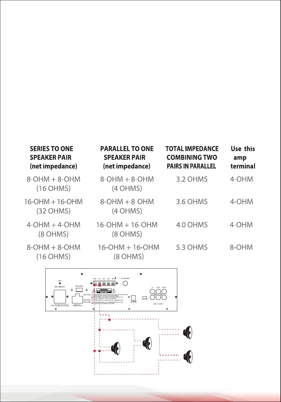
See the chart below for some samples system suggestions:
This example shows four 8 Ohm
Speakers, the total impedance is
8 ohms.
www.PyleUSA.com
10
SERIES/PARALLEL VARIATIONS
The description above explains how to combine two series pairs in a parallel
hook-up. However, you may also combine a series pair and a parallel pair in a
parallel hook-up. Make sure you have calculated the total impedance correctly,
and connect the (+) speaker circuit wire to the appropriate amplier terminal.
For example, if you use a series pair of 8-Ohm speakers (resulting in a total
impedance of 16 Ohms) and a parallel pair of 8-Ohm speakers (resulting in a total
impedance of 4 Ohms) in a parallel hook-up, the total impedance of this system is
3.2 Ohms. Therefore, you should connect the (+) speaker circuit wire to the 4-Ohm
terminal.
See the chart below for some samples system suggestions:
COMBINATION OF ONE SERIES PAIR AND ONE PARALLEL PAIR IN PARALLEL
+
-
+
-
+
-
+
-
8
8
8
8
Four 8 Ohm
Speakers
www.PyleUSA.com
11
This example shows the rst three systems in the chart. In this case, the 4-Ohm
terminal is used. Your system impedance may vary depending on the impedances
of the individual speakers and may require a connection to the 8 or 16 Ohm
terminal.
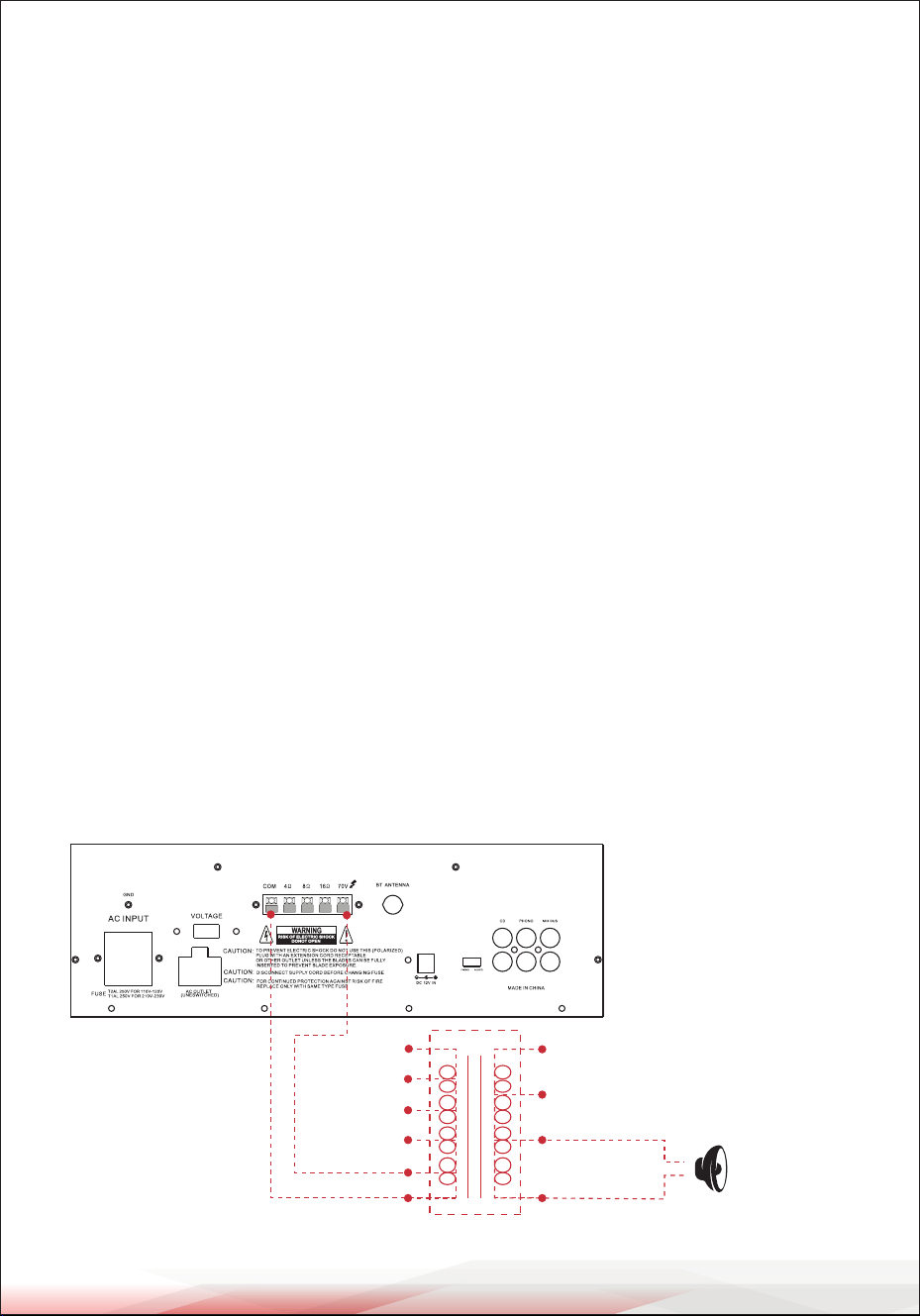
System 5: Connecting Speakers with Transformers
1. Locate the input taps on your transformer. These taps are on the side of the
transformer and are rated in watts (10, 5, 2.5, 1.25, or 0.62). Usually, each speaker
in a system uses the same wattage tap. Connect the selected tap to the amplier's
70V RMS terminal. If you want a particular speaker to have a higher volume level,
connect the wire from the 70V RMS to a higher wattage tap on the transformer.
2. Connect the transformer's COMMON tap on the primary side to the amplier's
COMMON terminal.
3. Connect the speaker's (+) terminals to the transformer's secondary tap that
matches the speaker's TOTAL IMPEDANCE. These secondary taps, located on
the opposite side of the transformer, are outputs rated in Ohms (4, 8, or 16).
4. Connect the speaker's (-) terminals to the transformer's COMMON tap on the
secondary side.
NOTE:
• Before connecting the speakers, please ensure the total wattage of the primary
tap you use does not exceed the amplier's maximum power rating:
PT110 (20W) and PT210 (40W).
• Avoid, where possible, multiple connections to the 70V RMS and COMMON
terminals.
4 Ohm 10w
Speaker
+
-
0.62
1.25
2.5
5
10
com
(watts)
com
(ohms)
16
8
4

USING HEADPHONES
To listen privately or to monitor sound sources, connect a pair of low-impedance
stereo headphones (not supplied) with a 6.35mm plug into the PHONES jack on
the amplier's front panel.
Please listen safely by following these recommendations:
Do not listen at extremely high volume levels. Extended, high-volume listening
can lead to permanent hearing loss. Always start with the volume control set to a
low level BEFORE you put the headphones on. Gradually increase the volume as
necessary.
CONNECTING TO STANDARD AC POWER
After making all other connections, set the POWER switch to the OFF position.
Then, connect the power cord to a standard AC outlet.
CONNECTING TO 4A/12V DC POWER
You can power the amplier from your vehicle's 12-volt battery.
Connect the supplied DC power cable's barrel plug to the DC 12V IN jack on the
amplier, and then connect the cable's other end to the 12-volt accessory socket
on the vehicle, such as the cigarette-lighter socket.
CAUTIONS:
Please unplug the AC power cord before connecting the DC power cable for
this 12V power usage, and disconnect the DC power cable before plugging in
the AC power cord for AC power usage. The vehicle using this power source
must have a negative ground electrical system. If you are not sure, please
check with your vehicle's dealer.
TURNING THE AMPLIFIER ON
1. Turn on the audio input source equipment connected to the amplier's INPUT
jack.
2. Set all volume levels (MASTER, MIC 1, MIC 2, and PHONO/AUX) to their minimum
settings.
3. Press the power switch to turn the amplier on.
4. Adjust the controls of MIC 1, MIC 2, and PHONO/AUX to achieve the desired
volume and balance.
www.PyleUSA.com
12

www.PyleUSA.com
13
USING THE MASTER VOLUME CONTROL
The MASTER volume control increases or decreases the output level gain. For best
performance with the least distortion, adjust the output level so that the LED
meter does not continually exceed the right extreme of the meter's range.
CAUTION: Setting the output level too high can overdrive the amplier and cause
permanent damage.
USING THE MIX BUS JACK
You can connect another PT110 or PT210 amplier to this jack to double the size
of your PA system. This allows you to use up to four microphones and two turntables
(or two auxiliary) sound sources. Use a shielded cable with phono plugs at each
end, and connect the cable between the MIX BUS jacks on the back of two
ampliers.
For best results, do not use a cable longer than 6 feet.
Mix Bus Jack

REMOTE CONTROL
1. Press this button to turn the MP3 on or o.
2. Press these two buttons to select the previous or next track in USB, SD, or
Bluetooth mode.
3. Adjust the volume up or down.
4. Press the number buttons to directly select tracks.
The unit takes 1–2 seconds to respond in USB or SD mode.
5. Press this button to repeat the current track.
6. Press this button to select the playing mode (USB/SD/Bluetooth).
7. EQ function: Select a pre-set mode of the equalizer that is designed accordingly.
8. Play and Pause function: Press this button to play or pause MP3 les in USB,
SD, or Bluetooth mode.
www.PyleUSA.com
14
1
2
3
4
5
6
7
8

www.PyleUSA.com
15
MAINTENANCE GUIDE
1. Clean Regularly: Use a soft, dry cloth to clean the amplier and associated
equipment.
2. Inspect Connections: Check cables and connections for damage, and replace if
necessary.
3. Ensure Ventilation: Keep vents clear to prevent overheating.
4. Protect from Moisture and Dust: Keep the amplier in a dry, clean environment.
5. Check Fuse: Replace blown fuses with the correct rating as needed.
6. Avoid Overloading: Do not exceed speaker or volume limits to prevent damage.
7. Keep Away from Heat: Avoid placing the amplier near heat sources.
STORAGE GUIDE
1. Power Down: Turn o the amplier and unplug it from the power source.
2. Store in a Dry Place: Keep the amplier in a cool, dry location.
3. Use Protective Cover: Protect the amplier from dust and dirt.
4. Avoid Stacking: Do not place heavy items on top of the amplier.
5. Organize Cables: Keep cables tidy to prevent damage.
6. Disconnect Peripherals: Remove external devices before storing the amplier.
7. Check Before Use: Inspect the amplier for damage before using it again.
By following these maintenance and storage tips, you can help extend the life of
your amplier and ensure its optimal performance.
Register Product
Thank you for choosing PyleUSA. By registering your product,
you ensure that you receive the full benets of our exclusive
warranty and personalized customer support.
Complete the form to access expert support and to keep your
PyleUSA purchase in perfect condition.
PyleUSA.com/register

Questions or Comments?
We are here to help!
Phone: 1.718.535.1800
PyleUSA.com/ContactUs