Loading ...
Loading ...
3
(22-11/16) C
(22-11/16)
C
J
I
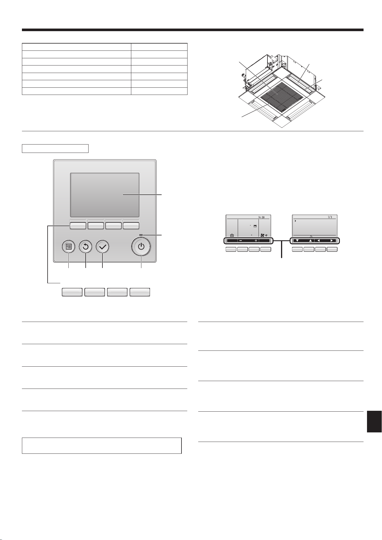
3. Installationdiagram
3.1. Indoorunit(Fig.3-1)
A Ceiling
B Grille
C Obstacle
D Min.1000mm(40inch)
E Min.500mm(20inch)(Entireperiphery)
If setting the maintenance space for E,besuretoleaveisaminimumof700mm(28inch).
Warning:
Mounttheindoorunitonaceilingstrongenoughtowithstandtheweightof
theunit.
3.2. Outdoorunit
Refer to the outdoor unit installation manual.
(inch)
Fig.3-1
Fig.4-1
4. Installingtheindoorunit
4.2. Ceilingopeningsandsuspensionboltinstallation
locations(Fig.4-2)
Caution:
Installtheindoorunitatleast2.4m(8ft)aboveoororgradelevel.
Forappliancesnotaccessibletothegeneralpublic.
• Usingtheinstallationtemplateandthegauge(suppliedasanaccessorywiththe
grille),makeanopeningintheceilingsothatthemainunitcanbeinstalledasshown
inthediagram.(Themethodforusingthetemplateandthegaugeareshown.)
* Before using, check the dimensions of template and gauge,because they
changeduetouctuationsoftemperatureandhumidity.
* The dimensions of ceiling opening can be regulated within the range shown in
followingdiagram;socenterthemainunitagainsttheopeningofceiling,en-
suringthattherespectiveoppositesidesonallsidesoftheclearancebetween
them becomes identical.
• UseM10(3/8")suspensionbolts.
* Suspensionboltsaretobeprocuredattheeld.
• Installsecurely,ensuringthatthereisnoclearance betweentheceilingpanel&
grille,andbetweenthemainunit&grille.
A Outer side of main unit
B Bolt pitch
C Ceiling opening
D Outer side of Grille
E Grille
F Ceiling
G Min.500mm(20inch)(Entireperiphery)
If setting the maintenance space for G,be
suretoleaveisaminimumof700mm(28
inch).
H Maintenancespace
I Fresh air intake
J Angle
K Electriccomponentbox
* Leavethemaintenancespaceattheelectriccomponentboxend.
*1When installing in an existing ceiling unit location or applying additional heat insulation,
ensureaminimumspaceof25mm(1inch).
Fig.4-2
9-21/32
13/32
24-19/32
24-19/32
C
D
E
A
B
1
2
3
4
5 6
4.1. Checktheindoorunitaccessories(Fig.4-1)
The indoor unit should be supplied with the following accessories.
Accessoryname Q’ty
1
Installation template 1
2
Washers(withinsulation)
Washers(withoutinsulation)
4
4
3
Pipecover(forrefrigerantpipingjoint)
smalldiameter(liquid)
largediameter(gas)
1
1
4
Band(large)
Band(middle)
Band(small)
6
2
2
5
Drain socket 1
6
Insulation 1
9/32to31/329/32to31/32
Min.18H
9/32to31/32
9/32to31/32
Min.18H
22-7/16A
20-21/32B
18-15/16
13-5/16
24-19/32D
22-11/16to24-1/32C
16-1/16
24-19/32
D
22-11/16to24-1/32
C
16-1/16
20-21/32B
22-7/16A
(inch)
5-29/32
3-15/32
*1
K
F
E
G
13/32
1-15/32
+3/16
0
Floor
Min.3/16
Min.94-1/2
5
7-7/16
2-1/16
1-31/32to3-5/8
9-21/32
8-3/16
Loading ...
Loading ...
Loading ...