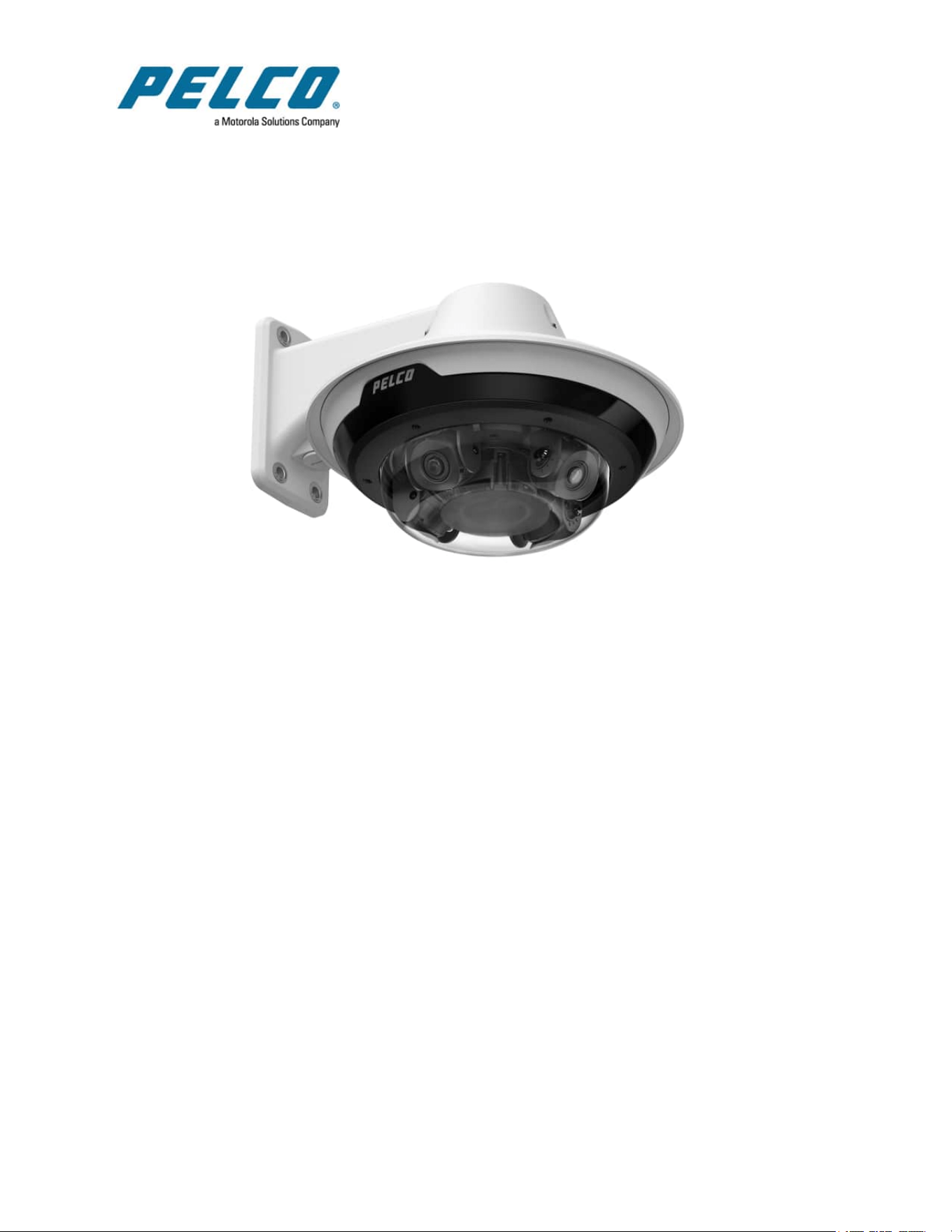

Sarix® Multi Pro Camera Installation Manual
C6715M | 01/24/22
2
Table of Contents
Overview 6
Camera Module 6
Camera Back View 6
Camera Top View 7
Surface Mount Adapter 8
Pendant Mount Adapter 9
In-Ceiling Mount Adapter 10
Outdoor Dome Cover 11
In-Ceiling Dome Cover 12
Pendant Wall Mount 13
Pendant NPT Mount 14
Preparing the Installation 15
Pre-Deployment In-Box Configuration 15
Pendant Mount Installation 16
Required Tools and Materials 16
Camera Package Contents 16
Pendant Mount Installation Steps 16
(Optional) Installing the Pendant Wall Mount 16
(Optional) Installing the NPT Mount Adapter 18
Installing the Pendant Mounting Adapter 20
Connecting Cables 21
(Optional) Configuring microSD Card Storage 23
Initializing a Camera Username and Password 24
Assigning an IP Address 24
Accessing the Live VideoStream 25
Installing the Sarix Multi Pro Camera Base to a Pendant Mount 25
Aiming the Sarix Multi Pro Camera 26
(Optional) Installing the IR Illuminator Ring 26
Installing the Pendant Mount Dome Cover 28
Surface Mount Installation 30
Camera Package Contents 30
Surface Mount Installation Steps 30
Installing the Surface Mount Adapter 30
Connecting Cables 35
(Optional) Configuring microSD Card Storage 37
Initializing a Camera Username and Password 38
Assigning an IP Address 38
Accessing the Live VideoStream 39
Installing the Sarix Multi Pro Camera Base to a Surface Mount 39
Aiming the Sarix Multi Pro Camera 40
(Optional) Installing the IR Illuminator Ring 40

Sarix® Multi Pro Camera Installation Manual
C6715M | 01/24/22
3
Installing the Surface Mount Dome Cover 42
In-Ceiling Mount Installation 44
Camera Package Contents 44
In-Ceiling Mount Installation Steps 44
Preparing the Camera for In-Ceiling Installation 44
(Optional) Cutting the Mounting Hole for the In-Ceiling Mount Adapter 45
(Optional) Attaching the Conduit Cable Entry Cover for Plenum Installations 45
Installing the In-Ceiling Mounting Adapter 47
Connecting Cables 49
(Optional) Configuring microSD Card Storage 51
Initializing a Camera Username and Password 52
Assigning an IP Address 52
Accessing the Live VideoStream 52
Installing the Sarix Multi Pro Camera Base to an In-Ceiling Mount 52
Aiming the Sarix Multi Pro Camera 53
Installing the In-Ceiling Mount Dome Cover 54
For More Information 55
Cable Connections 56
Connecting to Power, Audio, and External Devices 56
Pigtail Connector and Wires 56
Wiring Audio, I/O, and AUX Power 56
Focusing the Sarix Multi Pro Camera 57
Connection Status LED Indicator 58
Troubleshooting Network Connections and LED Behavior 58
Resetting to Factory Default Settings 59
Setting the IP Address Using the ARP/Ping Method 59
Cleaning 60
Dome Bubble 60
Body 60
Limited Warranty and Technical Support 61
Sarix® Multi Pro Camera Installation Manual
C6715M | 01/24/22
4
Important Safety Information
This manual provides installation and operation information and precautions for the use of this device.
Incorrect installation could cause an unexpected fault. Before installing this equipment read this manual
carefully. Please provide this manual to the owner of the equipment for future reference.
This Warning symbol indicates the presence of dangerous voltage within and outside the
product enclosure that may result in a risk of electric shock, serious injury or death to
persons if proper precautions are not followed.
This Caution symbol alerts the user to the presence of hazards that may cause minor or moderate
injury to persons, damage to property or damage to the product itself if proper precautions are not
followed.
Failure to observe the following instructions may result in severe injury or death.
l Installation must be performed by qualified personnel only, and must conform to all local codes.
l This product is intended to be supplied by a UL Listed Power Unit marked “Class 2” or “LPS” or
“Limited Power Source” with output rated:
l With IR LEDs: 24V AC ± 10%, 74 VA minimum, or 24 V DC ± 10%, 52 W minimum, PD-
9501GR/AC-NA-MSI, or PoE190-BT HPoE 802.BT single port injector 90W.
l Without IR LEDs: 24V AC ± 10%, 37 VA minimum, or 24 V DC ± 10%, 26 W minimum, or
25.5WPoE+, IEEE, 802.3at Type 2, PD-9001GR/AT/AC-MSI, PoEPlus (POE430-AT,
POE1236-AT, or POE2436-AT).
l Any external power supply connected to this product may only be connected to another Pelco
product of the same model series. External power connections must be properly insulated.
l Do not connect directly to mains power for any reason.
Failure to observe the following instructions may result in injury to persons or damage to the device.
l Do not install near any heat sources such as radiators, heat registers, stoves, or other sources of
heat.
l Do not subject the device cables to excessive stress, heavy loads or pinching.
l Do not open or disassemble the device. There are no user serviceable parts.
l Refer all device servicing to qualified personnel. Servicing may be required when the device has
been damaged (such as from a liquid spill or fallen objects), has been exposed to rain or moisture,
does not operate normally, or has been dropped.
l Do not use strong or abrasive detergents when cleaning the device body.
l Use only accessories recommended by Pelco.
Regulatory Notices
This device complies with part 15 of the FCC Rules. Operation is subject to the following two conditions:
(1)this device may not cause harmful interference, and (2) this device must accept any interference
received, including interference that may cause undesired operation.
This Class B digital apparatus complies with Canadian ICES-003.
This device complies with EN 60529 IP66 and IP67 rating (surface mount and pendant mount models).
Sarix® Multi Pro Camera Installation Manual
C6715M | 01/24/22
5
This equipment has been tested and found to comply with the limits for a Class B digital device, pursuant to
Part 15 of the FCC rules. These limits are designed to provide reasonable protection against harmful
interference in a residential installation. This equipment generates, uses and can radiate radio frequency
energy and, if not installed and used in accordance with the instructions, may cause harmful interference to
radio communications. However, there is no guarantee that interference will not occur in a particular
installation. If this equipment does cause harmful interference to radio or television reception, which can be
determined by turning the equipment off and on, the user is encouraged to try to correct the interference by
one or more of the following measures:
l Reorient or relocate the receiving antenna.
l Increase the separation between the equipment and the receiver.
l Connect the equipment into an outlet on a circuit different from that to which the receiver is
connected.
l Consult the dealer or an experienced radio/TV technician for help.
Changes or modifications made to this equipment not expressly approved by Pelco Corporation or parties
authorized by Pelco Corporation could void the user’s authority to operate this equipment.
To meet the requirements of the EN 50121-4 Railway Applications Standard, use an external power supply
or POE injector that is also compliant with EN 50121-4. Please contact Pelco for assistance regarding
supporting equipment.
Disposal and Recycling Information
When this product has reached the end of its useful life, please dispose of it according to your local
environmental laws and guidelines.
Risk of fire, explosion, and burns. Do not disassemble, crush, heat above 100 °C (212 °F), or incinerate.
European Union:
This symbol means that according to local laws and regulations your product should be disposed of
separately from household waste. When this product reaches its end of life, take it to a collection point
designated by local authorities. Some collection points accept products for free. The separate collection
and recycling of your product at the time of disposal will help conserve natural resources and ensure that it
is recycled in a manner that protects human health and the environment.
Sarix® Multi Pro Camera Installation Manual
C6715M | 01/24/22
6
Overview
Camera Module
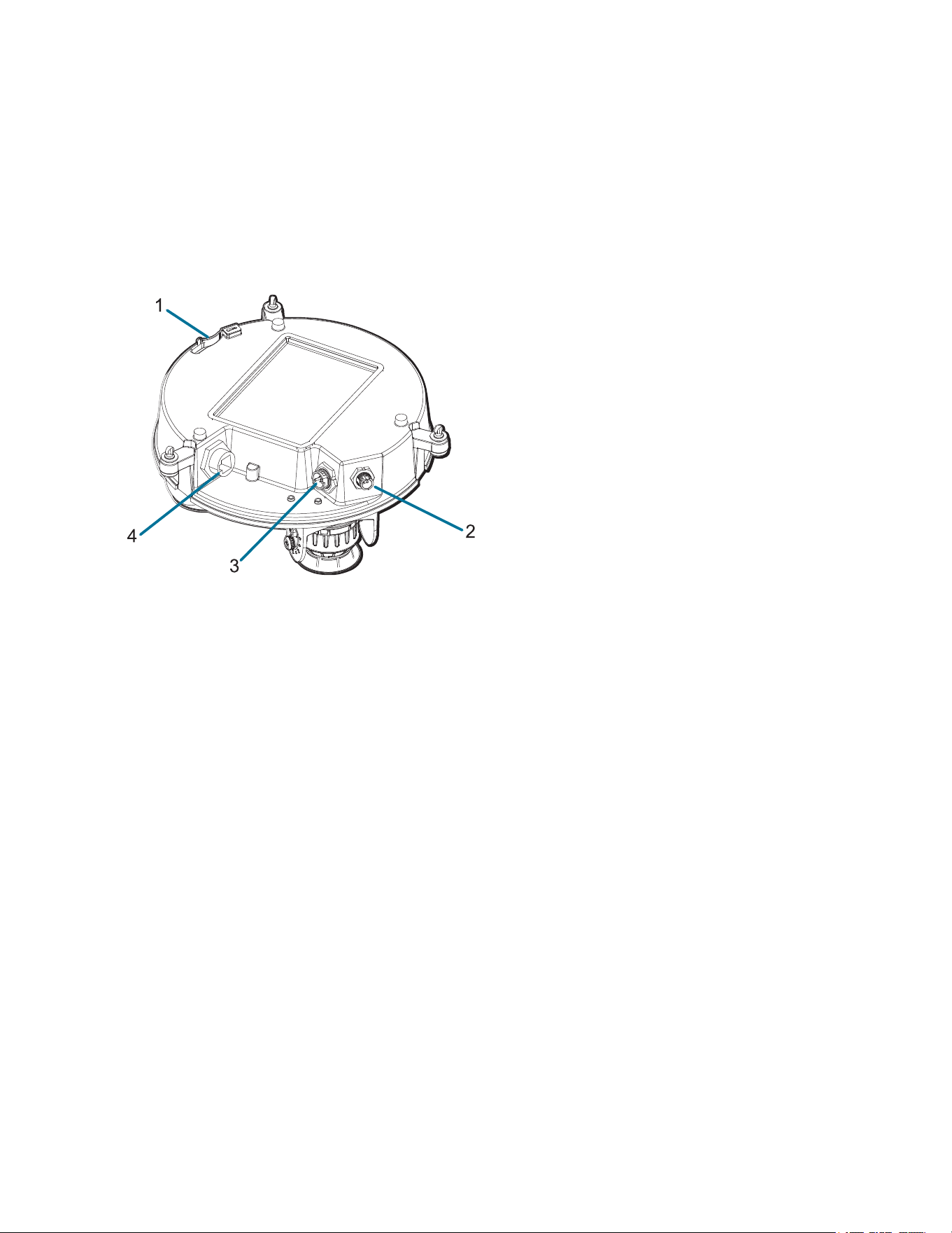
Camera Back View
1. Lanyard anchor
The safety lanyard attaches to the anchor to prevent the camera from falling during installation.
2. IR ring cable connector
Accepts IR cable connection to power and control the IR illuminator ring.
3. Audio, I/O, Aux power connector
Accepts connection of the audio, I/O, and Aux power pigtail connector.
4. Ethernet port
Accepts an Ethernet connection to a network. Server communication and image data transmission
occurs over this connection. Also receives power when it is connected to a network that provides
Power over Ethernet.
Sarix® Multi Pro Camera Installation Manual
C6715M | 01/24/22
7
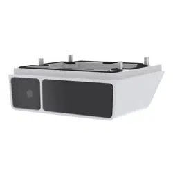
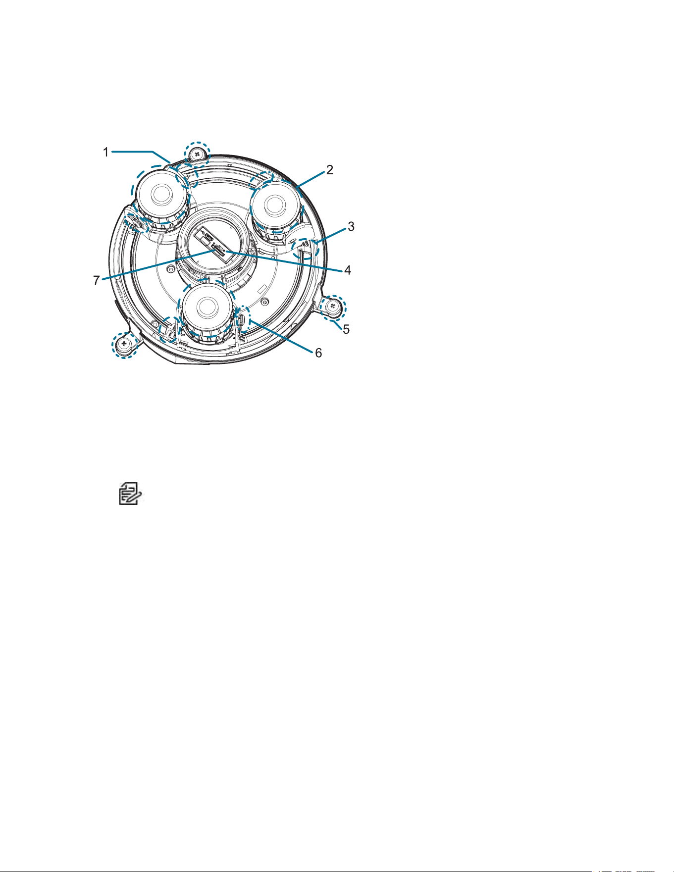
Camera Top View
1. Serial number tag
Device information, product serial number and part number label.
2. Camera heads
The multiple camera heads that can be moved, aimed and focused to monitor different scenes.
Note:
There may be three or four camera heads depending on your camera model.
3. Pan lock latch
Provides a locking mechanism for the image pan adjustment.
4. Firmware revert button
Resets the Sarix Multi Pro camera. For more information, see Resetting to Factory Default
Settings.
5. Camera mounting screws
Captive screws to fix the camera to the mounting adapter.
6. Tilt lock thumb screw
Provides a locking mechanism for the image tilt adjustment.
7. microSD card slot
Accepts a microSD card for onboard storage.
Sarix® Multi Pro Camera Installation Manual
C6715M | 01/24/22
8
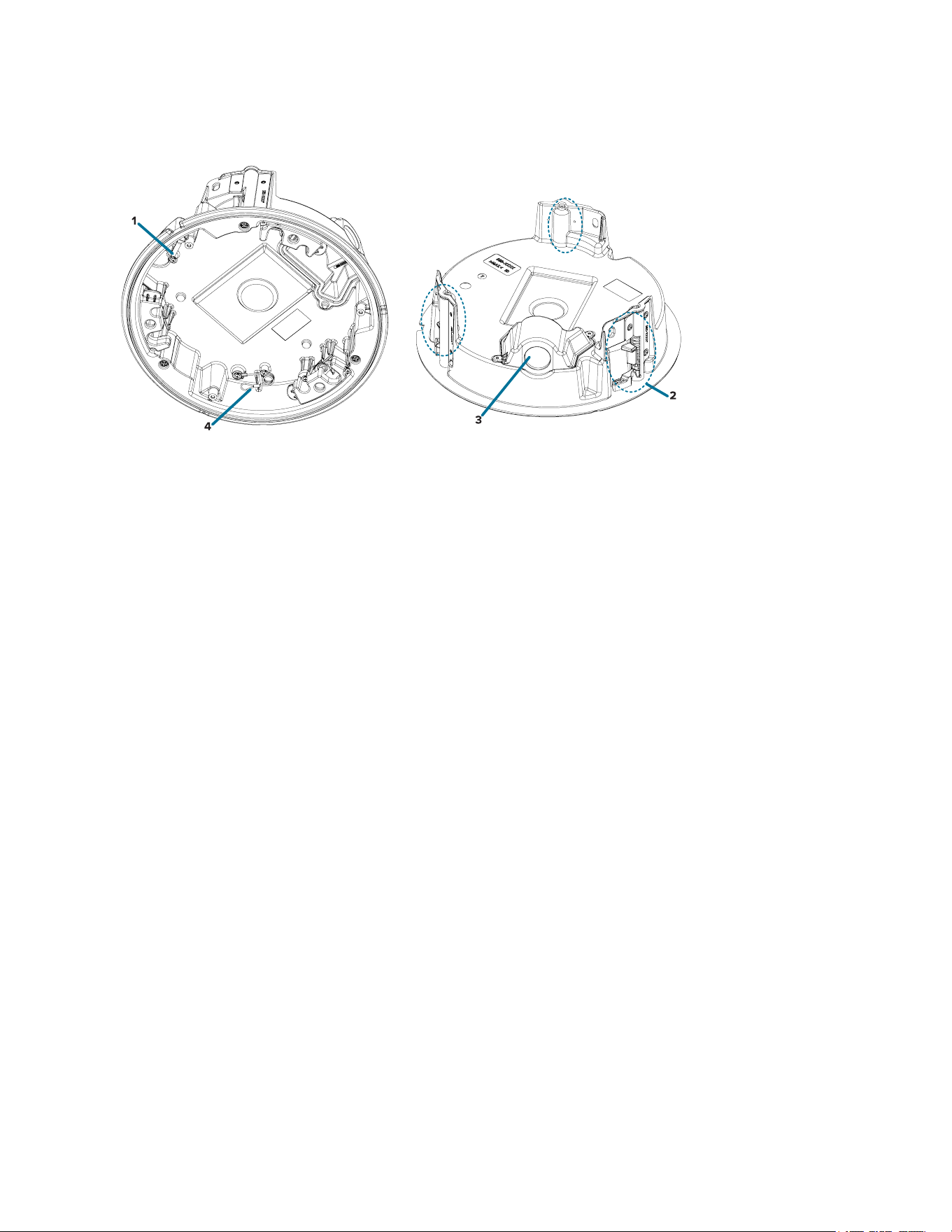
Surface Mount Adapter
1. Lanyard to camera
Connects to the lanyard anchor on the camera base.
2. Cable entry hole (rear)
An entry hole for the cables required for camera operation.
3. Cable entry hole (side)
An entry hole for the cables required for camera operation.
4. Mounting holes
Mounting points for the mount adapter.
5. Lanyard to dome cover
Connects to the lanyard anchor on the dome cover.
Sarix® Multi Pro Camera Installation Manual
C6715M | 01/24/22
9
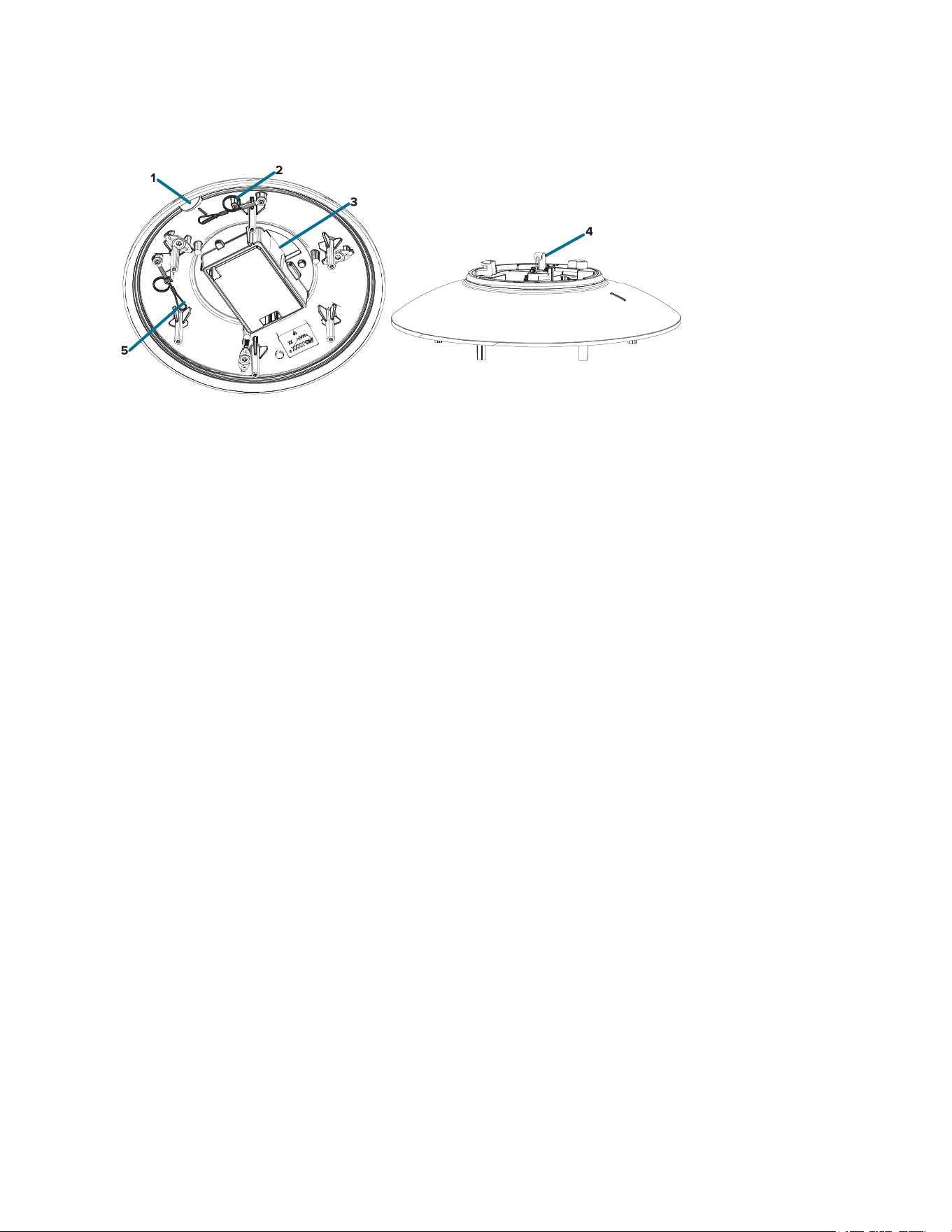
Pendant Mount Adapter
1. Alignment tab
An alignment tab is used to align with the lanyard clip on the dome cover.
2. Lanyard to dome cover
Connects to the lanyard anchor on the dome cover.
3. Cable entry hole
An entry hole for the cables required for camera operation.
4. Lanyard anchor
The safety lanyard attaches to the anchor to prevent the adapter from falling during installation.
5. Lanyard to camera
Connects to the lanyard anchor on the camera base.
Sarix® Multi Pro Camera Installation Manual
C6715M | 01/24/22
10
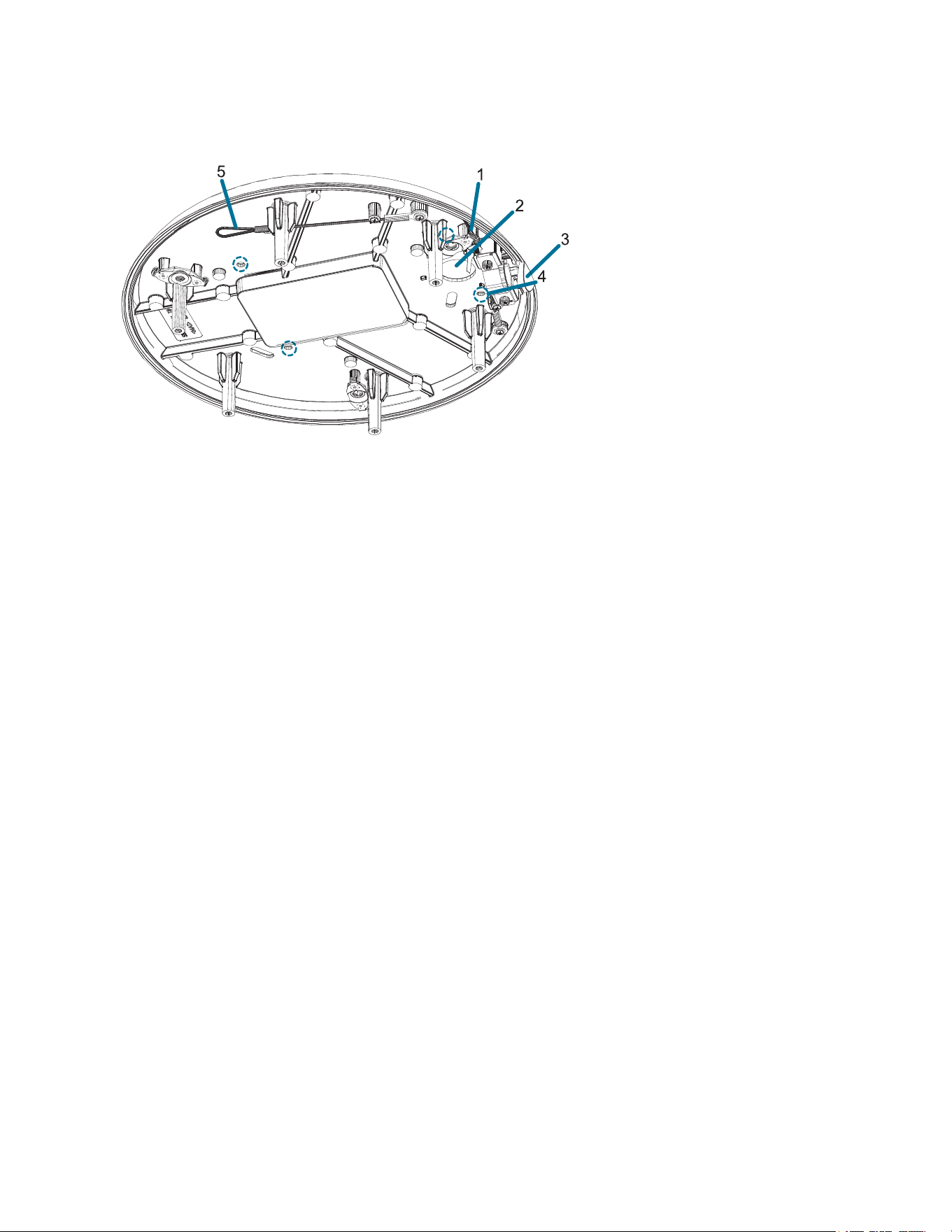
In-Ceiling Mount Adapter
1. Lanyard to camera
Connects to the lanyard anchor on the camera base.
2. Clamps
Spring loaded locking mechanisms that secure the camera to the mounting surface.
3. Cable entry hole and conduit cable entry cover
An entry hole for the cables required for camera operation.
4. Lanyard to dome cover
Connects to the lanyard anchor on the dome cover.
Sarix® Multi Pro Camera Installation Manual
C6715M | 01/24/22
11
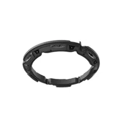
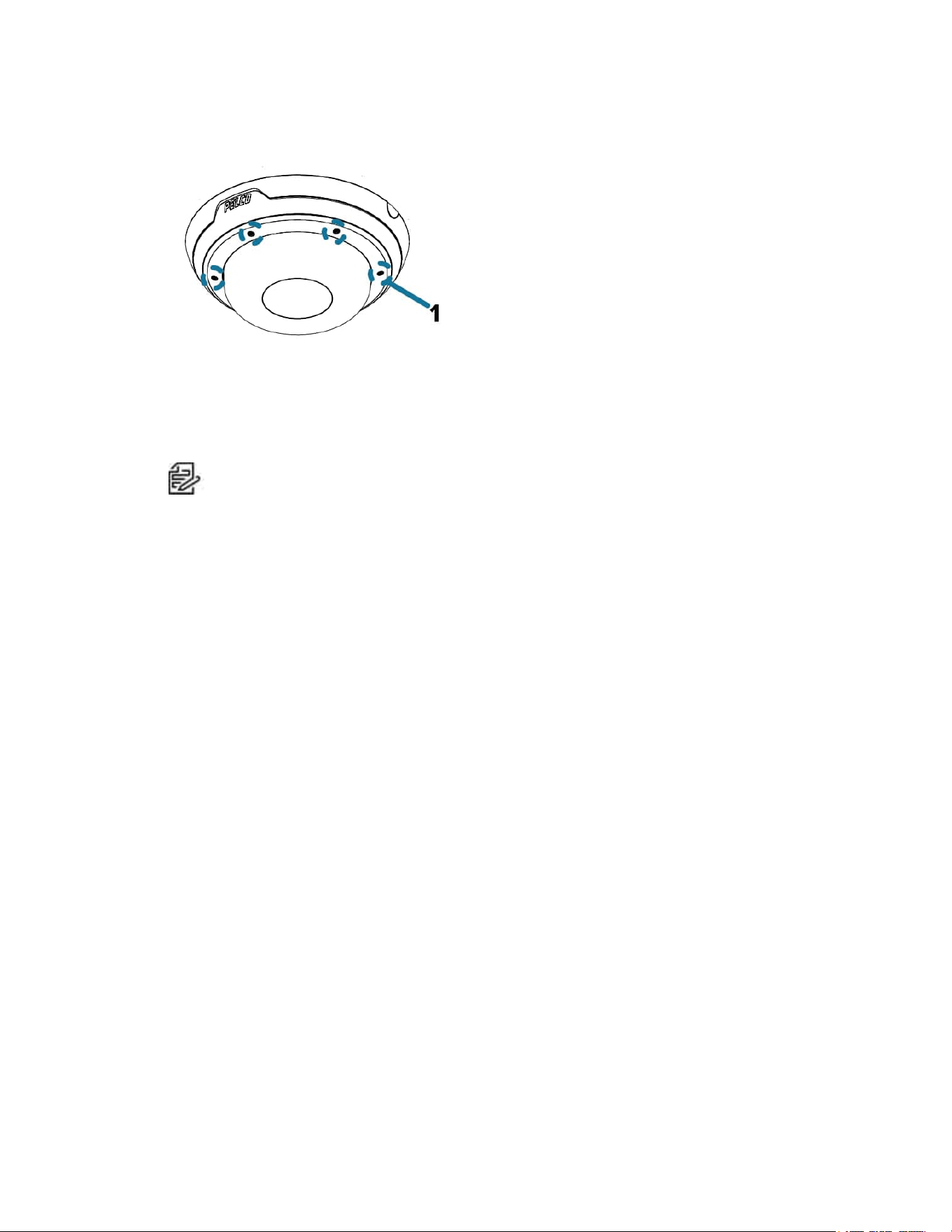
Outdoor Dome Cover
1. Tamper resistant screws
Star-shaped captive screws to fix the dome cover to the base.
Note: There are 6 captive screws on the dome cover. Only 4 screws are shown in the figure
above.
Sarix® Multi Pro Camera Installation Manual
C6715M | 01/24/22
12
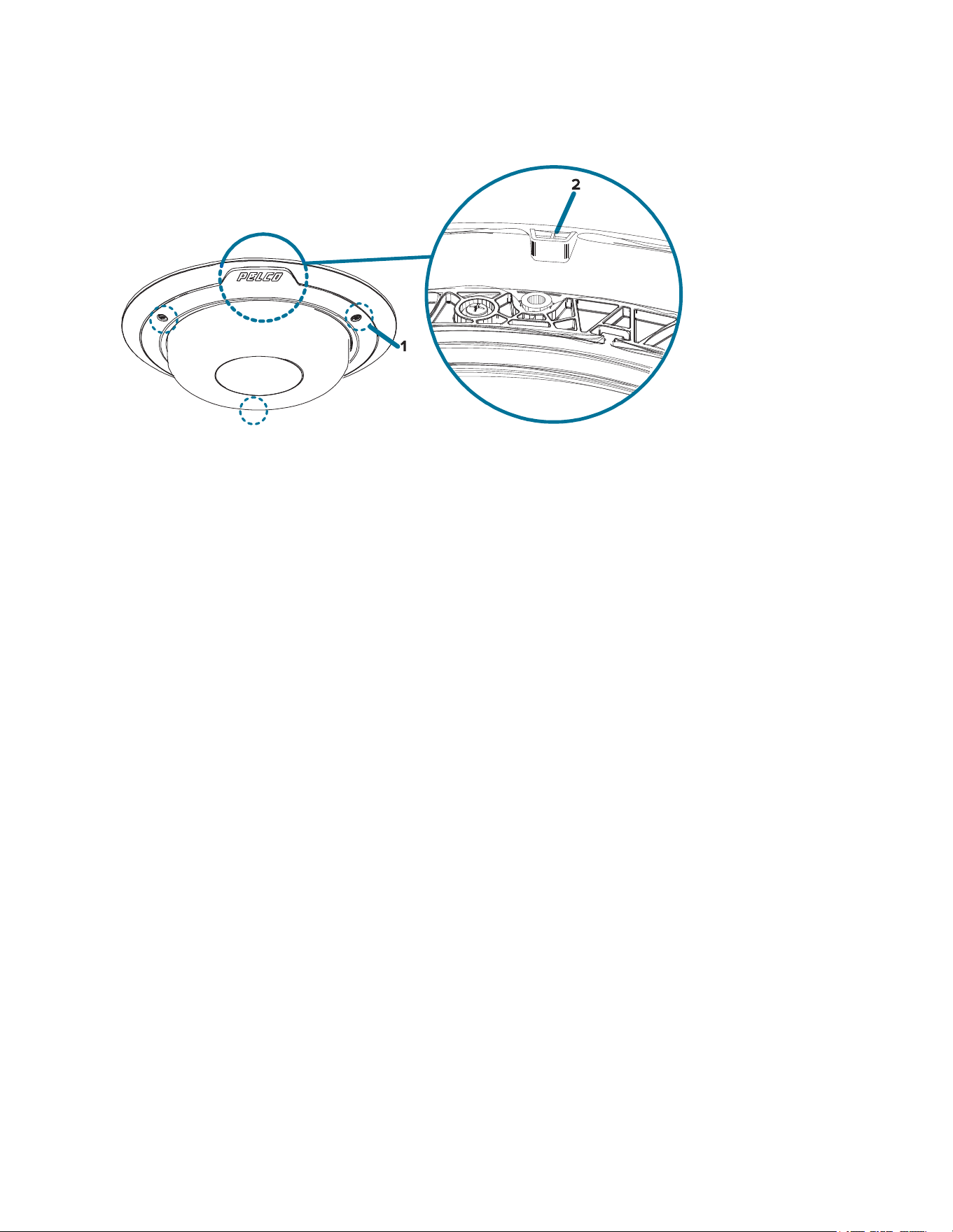
In-Ceiling Dome Cover
1. Tamper resistant screws
Star-shaped captive screws to fix the dome cover to the base.
2. Dome cover notch
Notch used to align the dome cover with the mounting adapter clip notch when installing the dome
cover.
Sarix® Multi Pro Camera Installation Manual
C6715M | 01/24/22
13
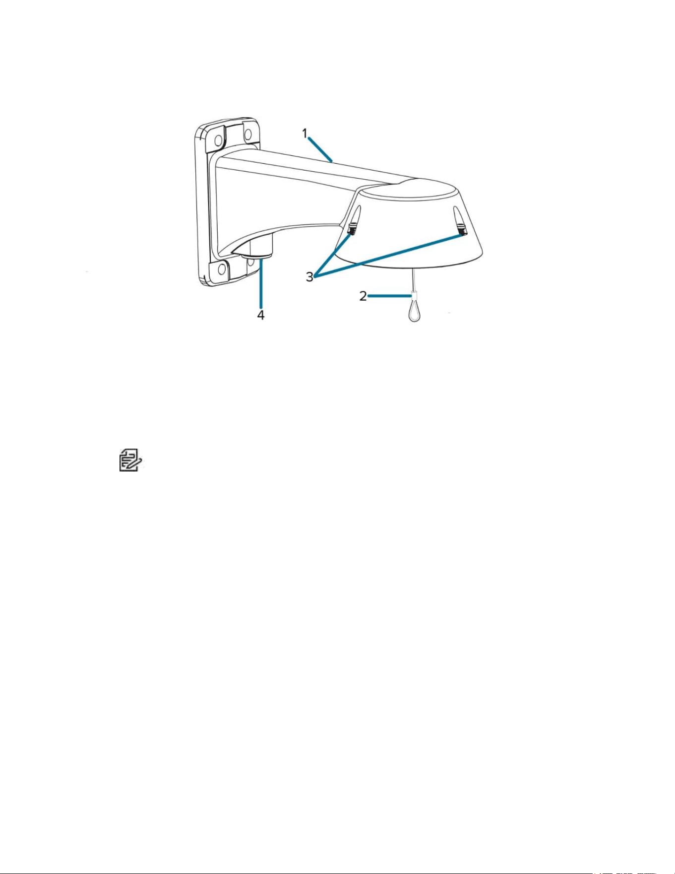
Pendant Wall Mount
1. Pendant wall mount
Camera mount for walls and other mounting surfaces.
2. Lanyard
Connects to the lanyard anchor on the mounting adapter.
3. Tamper resistant screws
Star-shaped captive screws to fix the mounting adapter to the pendant wall mount.
Note: There are 3 captive screws on the pendant mount. Only 2 screws are shown in the
figure above.
4.1. NPT pipe entry hole
A 3/4” NPT threaded hole for NPT pipe conduits.
Sarix® Multi Pro Camera Installation Manual
C6715M | 01/24/22
14
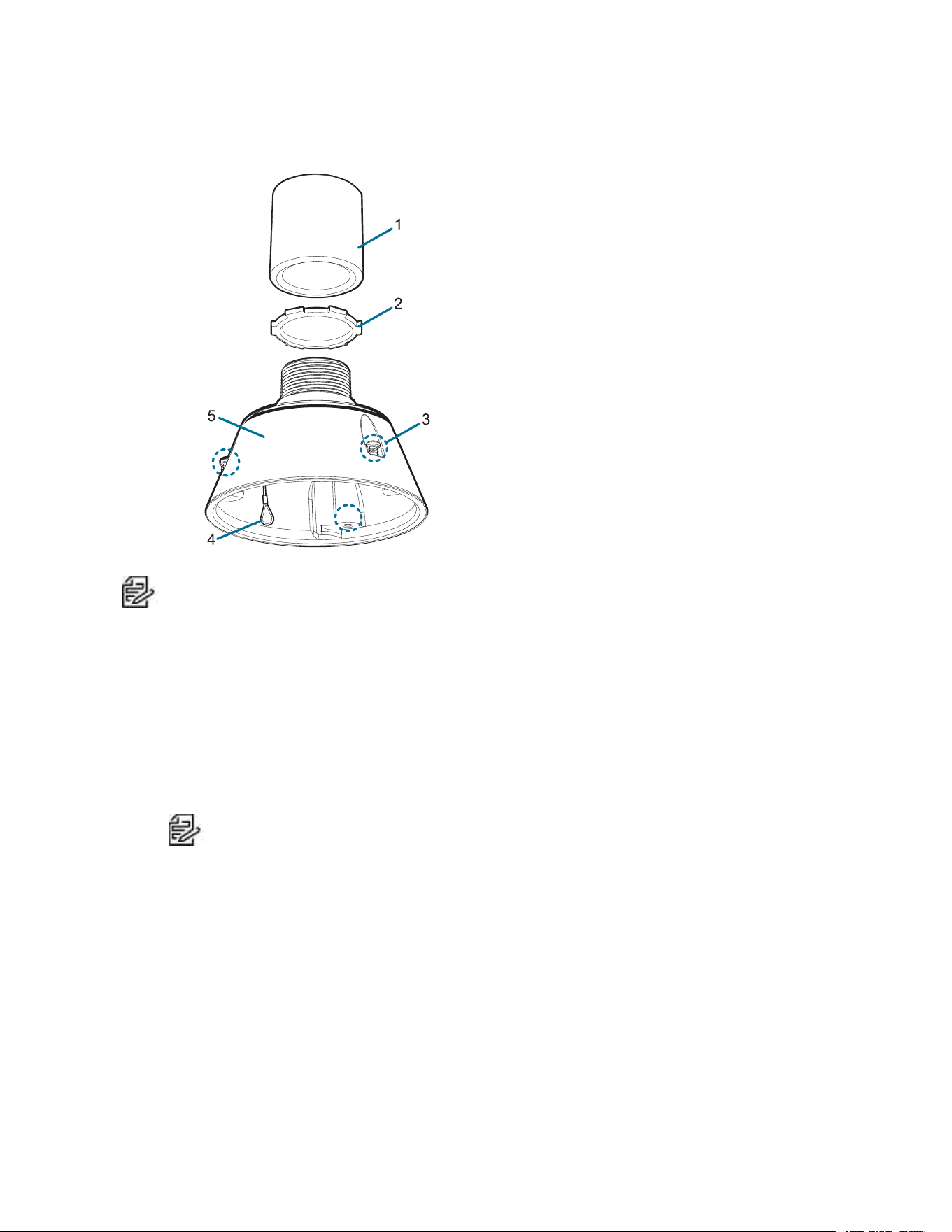
Pendant NPT Mount
Note: The NPT pipe and NPT-female to NPT-female adapter are not supplied by Pelco and should
be sourced separately. However, if you are using the NPT adapter (NPTA-1001), the lock nut is
included.
1. NPT-female to NPT-female adapter
Adapter used for mounting NPT adapter (NPTA-1001) to an NPT pipe.
2. Lock nut
Locking nut for securing the pendant NPT mount on the NPT pipe.
3. Tamper resistant screws
Star-shaped captive screws to fix the mounting adapter to the pendant NPT mount.
Note:
There are 3 captive screws on the NPT mount. Only 2 screws are shown in the figure
above.
4. Lanyard
Connects to the lanyard anchor on the mounting adapter.
5. NPT adapter
Used to mount the dome camera to NPT pipes.

Sarix® Multi Pro Camera Installation Manual
C6715M | 01/24/22
15
Preparing the Installation
Pre-Deployment In-Box Configuration
The camera comes equipped with an RJ45 configuration cable pre-installed for users that want to configure
camera settings before installing the camera. The RJ45 connector on the configuration cable is accessible
through the small flap on the side of the camera box for easy configuration before unpacking the camera.
We recommend that you do not exceed 3 hours of leaving your camera connected during in-box
configuration with ambient temperatures between 20 °C – 25 °C (68 °F – 77 °F).
1. Locate and open the flap on the side of the camera packaging.
2. Connect a network cable to the RJ45 plug on the configuration cable. The network cable must
provide PoE. IEEE 802.3af Class 3, to power the camera during configuration.
3. Connect to the camera using a video management system, the Camera Configuration Tool, or the
camera's web browser interface to configure the camera's settings. For more information about
connecting to the camera, see Assigning an IP Address, and Accessing the Live VideoStream.
4. Once you have finished making configuration changes, unplug the network cable.
Warning: Be careful when handling the camera after configuring it inside the packaging. The camera
may be hot when handling it or removing from the packaging immediately after in-box configuration.

Sarix® Multi Pro Camera Installation Manual
C6715M | 01/24/22
16
Pendant Mount Installation
Required Tools and Materials
The following tools are required to complete the installation but are not included in the package:
If you will be installing the NPT adapter (NPTA-1001), you will need:
l 1-1/2" NPT female to female adapter
l NPT pipe
Camera Package Contents
The Sarix Multi Pro camera has a variety of different mounting, dome cover, camera and accessory
options. The components for each Sarix Multi Pro camera will arrive in a camera package, a dome cover
package, a mounting adapter package, a mount package (for pendant mount cameras), and a metal ceiling
panel package (for in-ceiling cameras).
Ensure the camera package contains the following:
l Pelco Sarix Multi Pro Camera module. A 3- or 4-sensor camera module with 3 MP, 5 MP, or 4K (8
MP) resolution per sensor.
l Audio, external power, and I/O pigtail cable connector
l RJ45 CAT5E plugs (x2)
l RJ45 connector waterproof gland
Ensure the Pendant mount adapter package contains the following:
l Pendant mount adapter (IMD1-PMT)
l Installation instructions sheet
If you are installing the camera with the pendant wall mount, ensure the package includes the following:
l Pendant wall mount (WLMT-1001)
l Mounting template sticker
If you are installing the camera with the NPT mount, ensure the package includes the following:
l NPT mount (NPTA-1001)
l Lock nut
l Thread sealing tape
Ensure the dome cover package contains the following:
l Clear or smoked dome bubble and cover (IMD1-INCLD1 or IMD1-SPLD0)
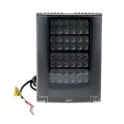
If you are installing the camera with the optional IR illuminator, ensure the package includes the following:
l IR illuminator ring (IMD1-IR)
Pendant Mount Installation Steps
Complete the following sections to install the device.
(Optional) Installing the Pendant Wall Mount
Use the procedure below to install the pendant wall mount (WLMT-1001) for use with the Sarix Multi Pro
pendant mount adapter (IMD1-PMT).
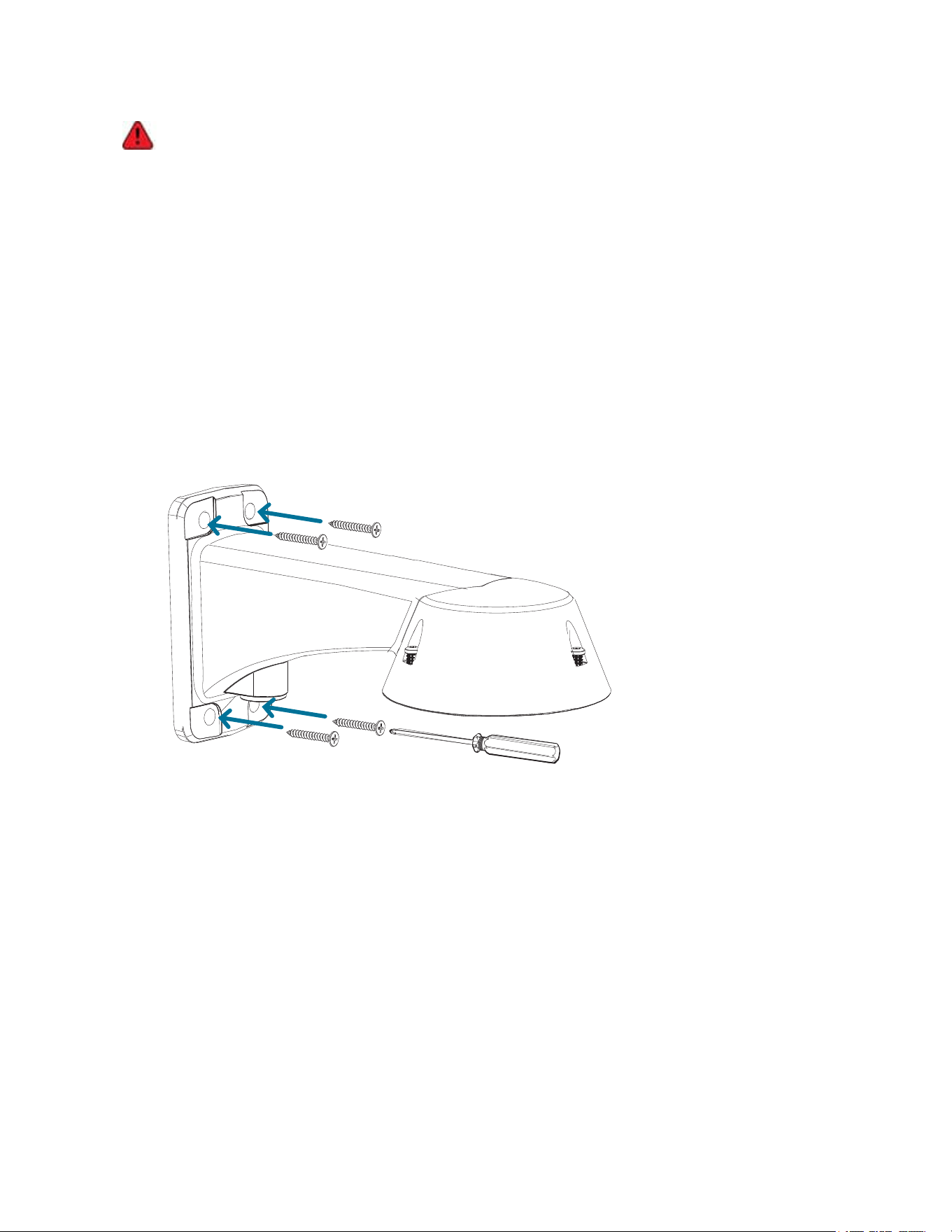
Sarix® Multi Pro Camera Installation Manual
C6715M | 01/24/22
17
The dome camera must be mounted as instructed below or problems with moisture may arise and
will not be covered by the dome camera warranty.
1. Determine where the cables will enter the pendant wall mount.
l If the cables will be pulled from inside the mounting surface, use the cable entry hole at the rear
of the pendant wall mount.
l If the cables will be coming out of an external conduit pipe, use the 3/4” NPT pipe entry hole on
the bottom of the pendant wall mount.
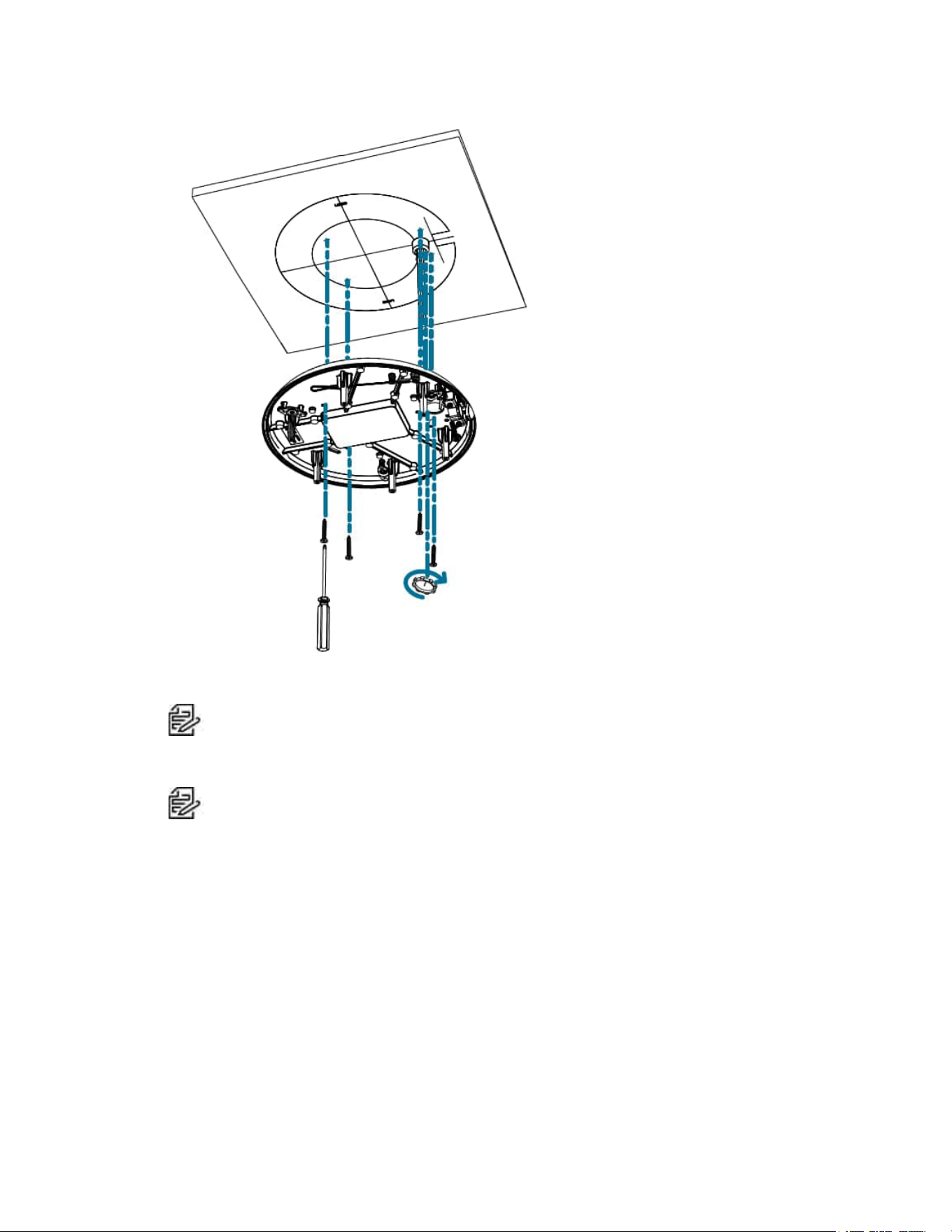
2. Use the provided mounting template to drill four mounting holes into the mounting surface.
l If you are using the rear cable entry hole, also drill the cable entry hole into the mounting
surface.
3. Pull the required cables through the preferred cable entry hole on the pendant wall mount.
l If you are using the pipe entry hole, pull the cables through the pipe conduit then the wall mount.
Next, apply thread seal tape to the pipe conduit and screw it into the pipe entry hole.
4. Fasten the pendant wall mount to the mounting surface.
5. Tighten the wall mount screws to secure the wall mount to the wall.
6. Connect the safety lanyard from the mount to the anchor on the pendant adapter.
Sarix® Multi Pro Camera Installation Manual
C6715M | 01/24/22
18
7. Pull the cables through the pendant wall mount.
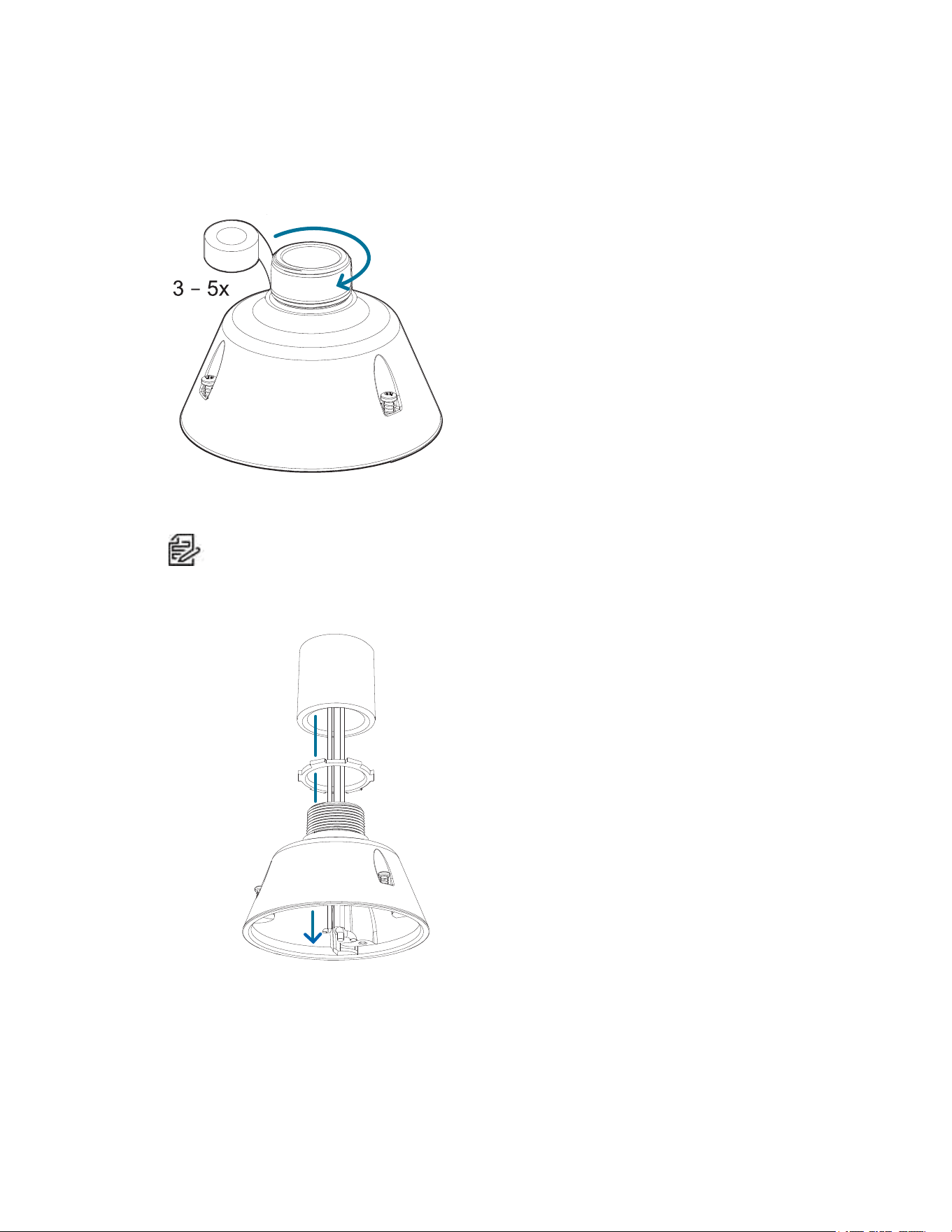
(Optional) Installing the NPT Mount Adapter
The dome camera must be mounted as instructed below or problems with moisture may arise and
will not be covered by the dome camera warranty.
If you are installing the Sarix Multi Pro camera with an NPT adapter (NPTA-1001), the dome camera must
be mounted on a 1-1/2” NPT female threaded wall or ceiling mounting bracket. The mounting bracket is not
included in the camera package.
Note: The NPT pipe and NPT-female to NPT-female adapter are not supplied by Pelco and should
be sourced separately. However, if you are using the NPT adapter (NPTA-1001), the lock nut is
included.
Sarix® Multi Pro Camera Installation Manual
C6715M | 01/24/22
19
1.1. Wrap the thread of the NPT adapter with the supplied thread-sealing tape to create a water tight seal
around the camera connection. There should be three to five turns around the entire threaded
surface.
When applying the thread-sealing tape, wrap the tape clockwise.
This will ensure the tape does not unravel when installing the mating parts together.
Tip
: Always apply thread-sealing tape to threaded mounts to help prevent the threads from
binding.
2. Loosely thread the lock nut onto the NPT adapter, then secure the NPT adapter into the wall or
ceiling mounting bracket.
3. Connect the safety lanyard from the mount to the anchor on the pendant adapter.
Sarix® Multi Pro Camera Installation Manual
C6715M | 01/24/22
20
4. Pull the cables through the mounting bracket and adapter.
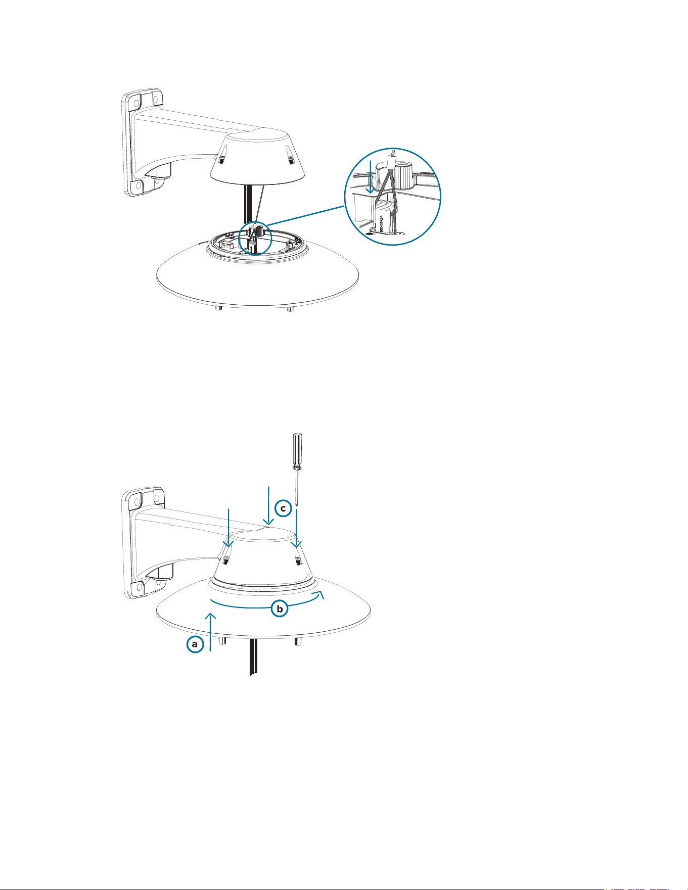
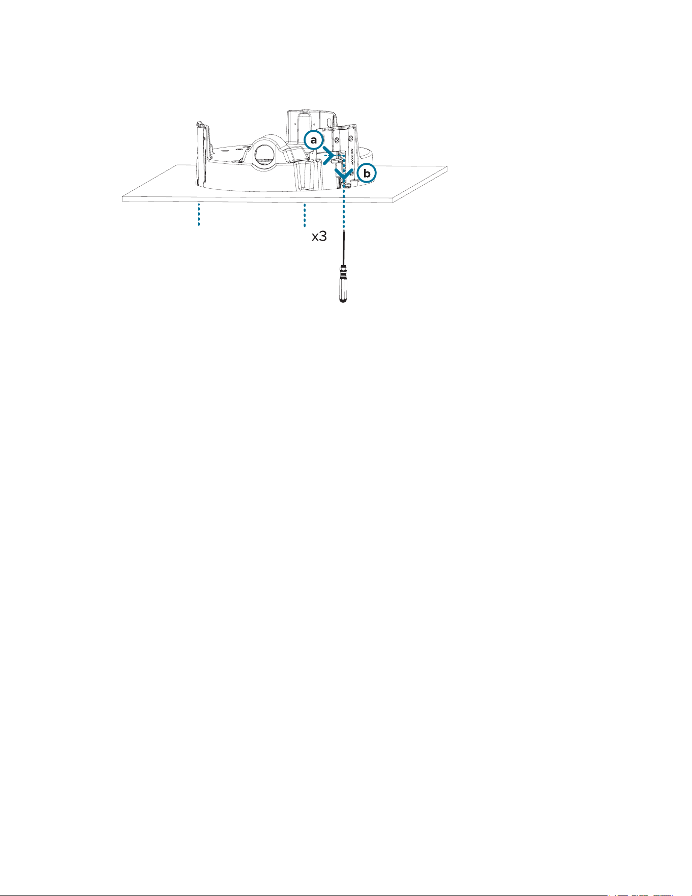
Installing the Pendant Mounting Adapter
Use the following procedure to mount the pendant adapter (IMD1-PMT) into a pendant wall mount (WLMT-
1001) or NPT mount (NPTA-1001).
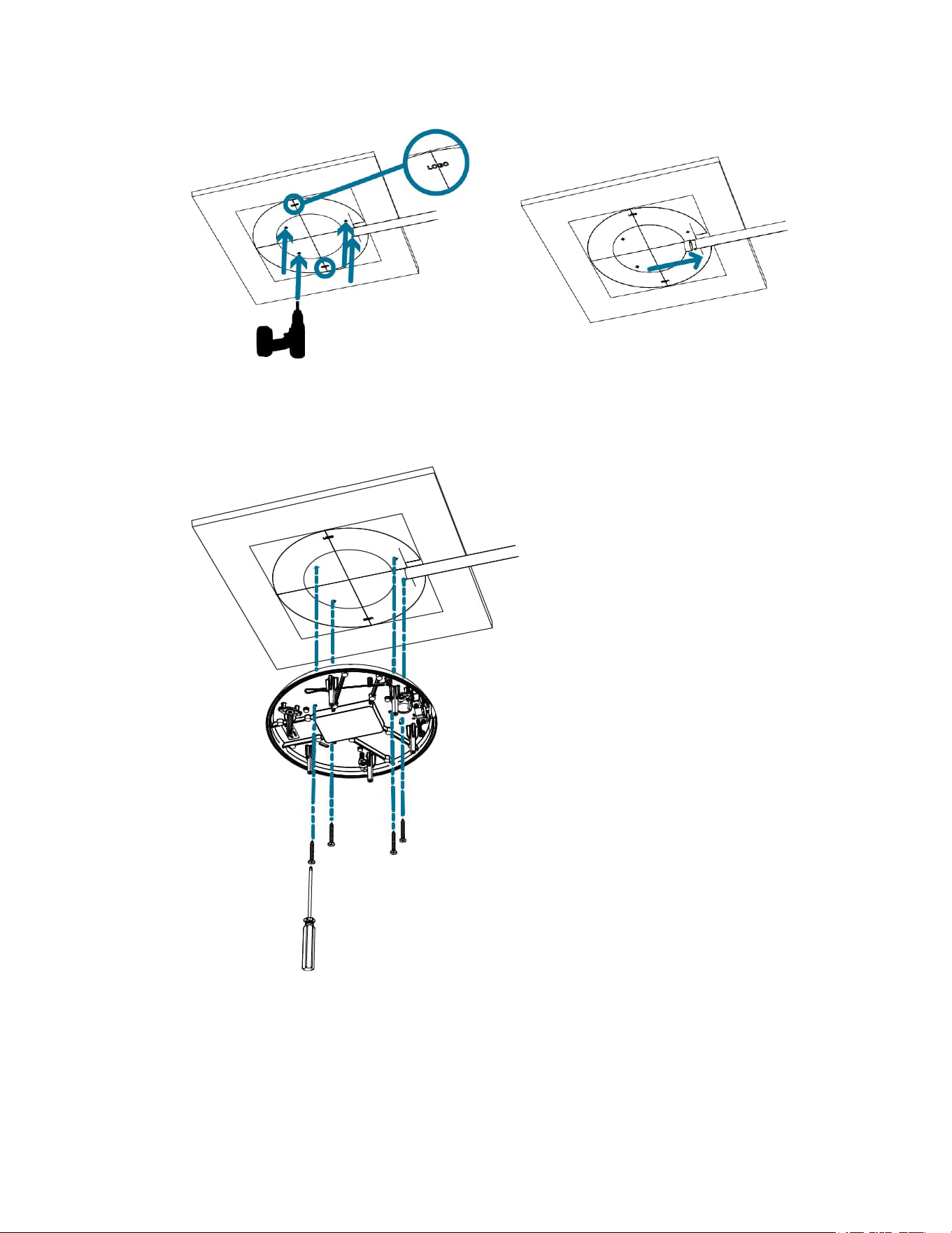
1. Connect the pendant adapter to the mount. In one smooth motion, raise the adapter into the mount
(a) and then turn clockwise to lock the adapter in place (b).
2. Use a screwdriver to tighten the 3 setscrews at the top of the mount to secure the pendant adapter
to the mount (c).
Sarix® Multi Pro Camera Installation Manual
C6715M | 01/24/22
21
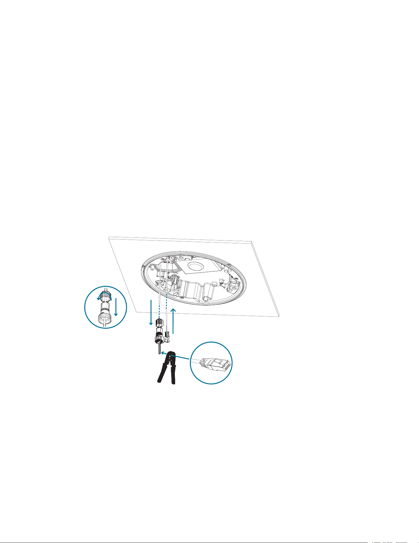
Connecting Cables
Refer to the diagrams in the Overview section for the location of the different connectors.
To connect the cables required for proper operation, complete the following:
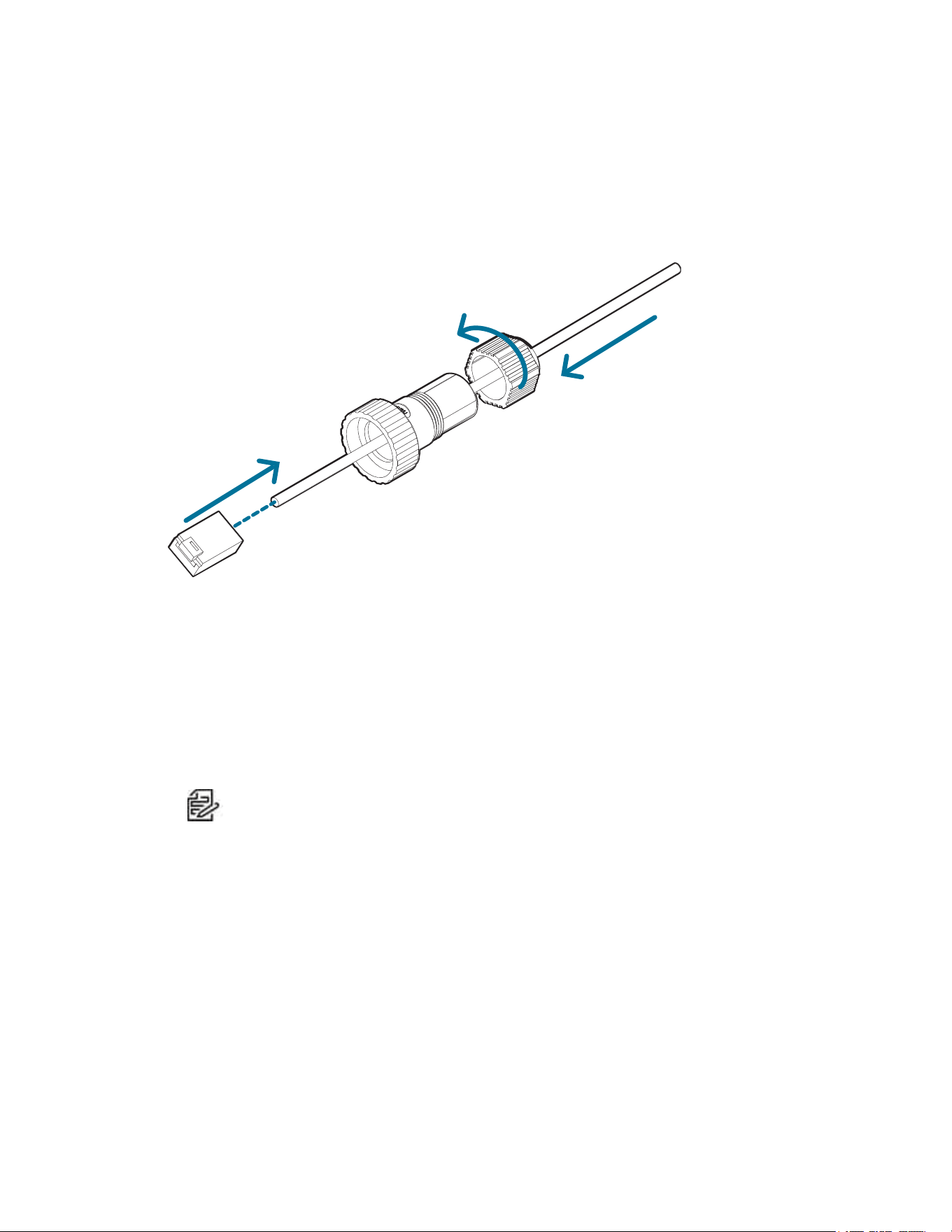
1. Feed the network cable through the gland cap and cable gland. Crimp the RJ-45 cable connector
(supplied) to the end of your network cable.
The network cable connection can also be used to supply power to the camera using Power over
Ethernet (PoE). If using PoE, connect a PoE compliant injector or switch to the Ethernet network
cable with the output rated:
l With IR Ring: 60W PoE mid-span injector (PD-9501GR/AC-NA-MSI and include POE190-BT).
Alternatively, connect to a Cisco® UPoE capable switch, supporting 60W over 4 pairs. Note
that the Cisco switch must be configured with the Force Four Pair option enabled.
l Without IR Ring: Power over Ethernet (PoE) Plus, PD-9001GR/AT/AC-MSI, IEEE 802.3at
Class 4 — Connect a PoE Plus compliant injector or switch (e.g. POE430-AT, POE1236-AT, or
POE2436-AT).
Note: When on UPoE and without an IR ring, the Sarix Multi Pro will continue to request
60W power on startup, as the IR ring is a hot-pluggable add-on accessory. If the IRring
accessory will never be used, the recommendation is to limit the available power to PoE
plus equivalent on the Cisco switch settings.
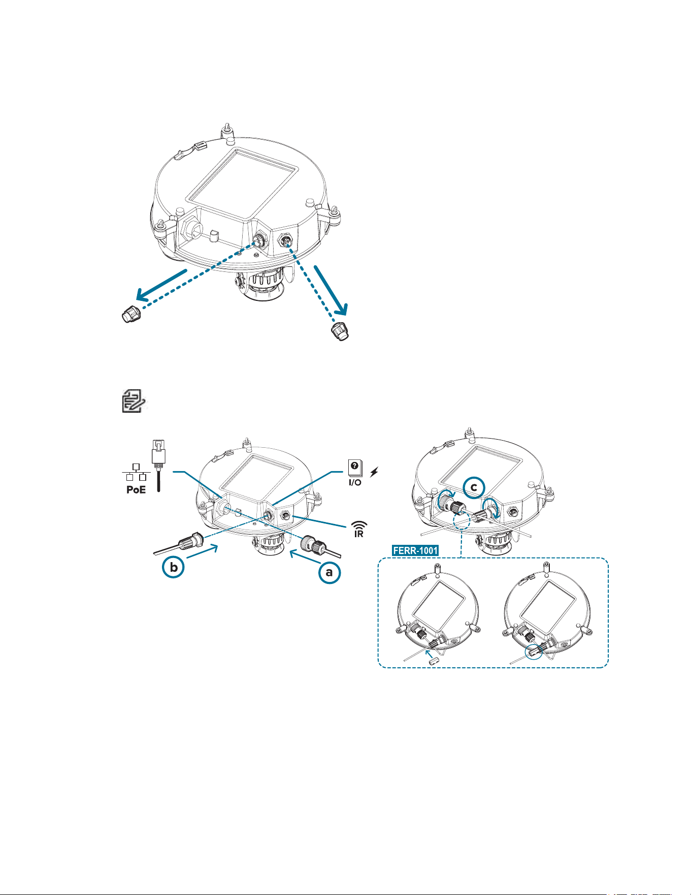
2. Connect the following optional connections to the supplied pigtail I/O connector. See Connecting to
Power, Audio, and External Devices for more information on the different connections.
a. If external input or output devices are part of the installation (for example: door contacts,
relays, etc.), wire those devices to the pigtail connector.
b. If an external microphone or speaker is required, connect the devices to the pigtail connector.
c. If external power is required, connect an external "Class 2" or "LPS" or "Limited Power Source"
to the pigtail connector with output rated:
Sarix® Multi Pro Camera Installation Manual
C6715M | 01/24/22
22
l With IR Ring: 24 VAC ± 10%, 74 VA minimum, or 24 VDC ± 10%, 52 W minimum.
l Without IR Ring: 24 VAC ± 10%, 37 VA minimum, or 24 VDC ± 10%, 26 W minimum.
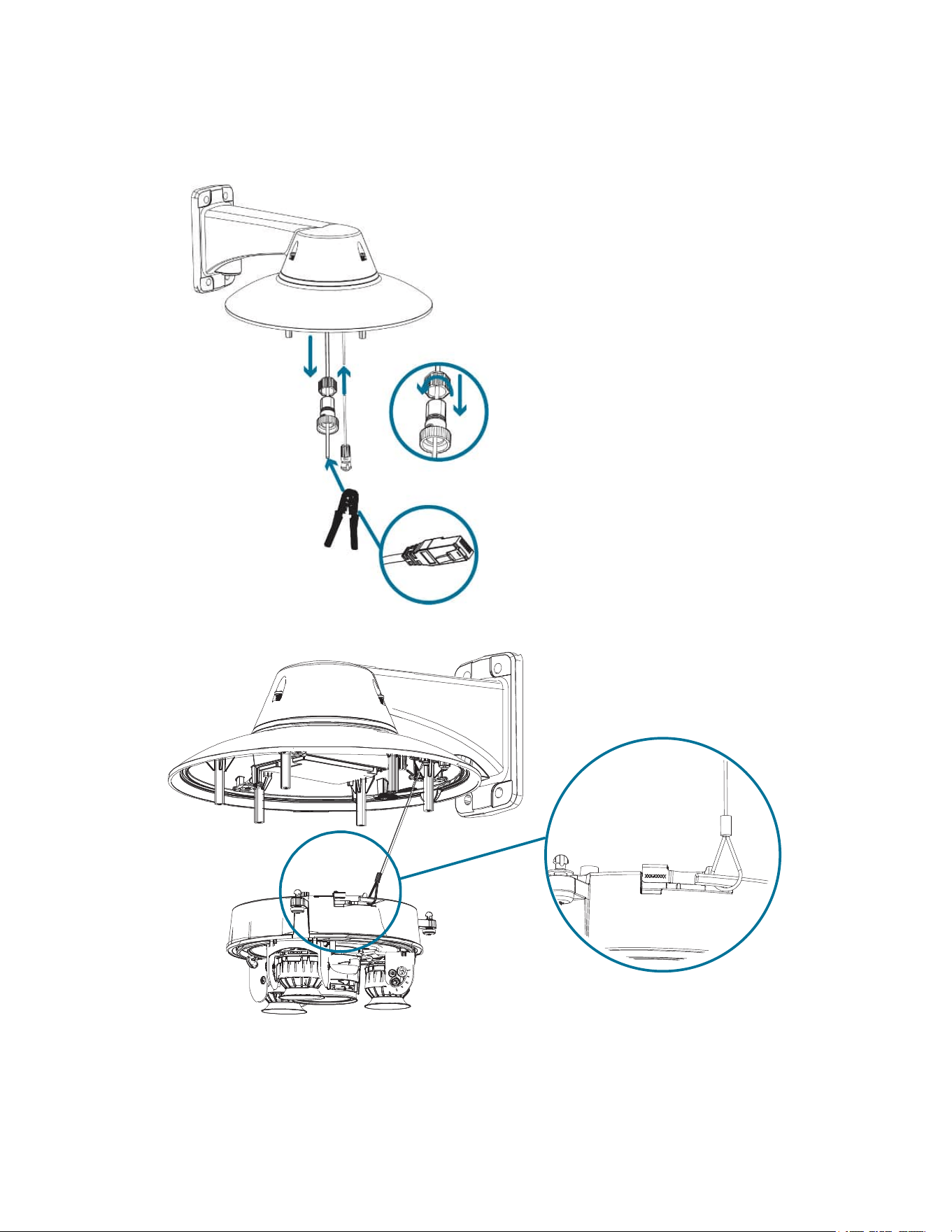
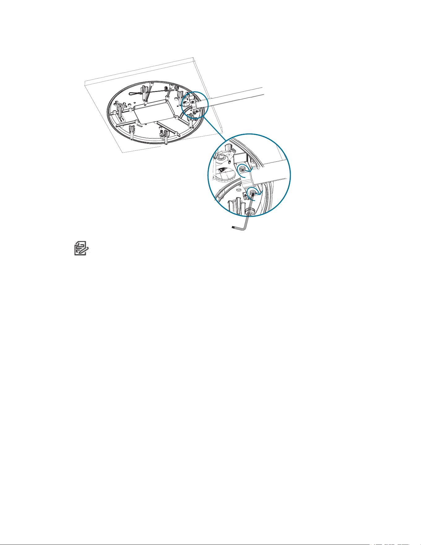
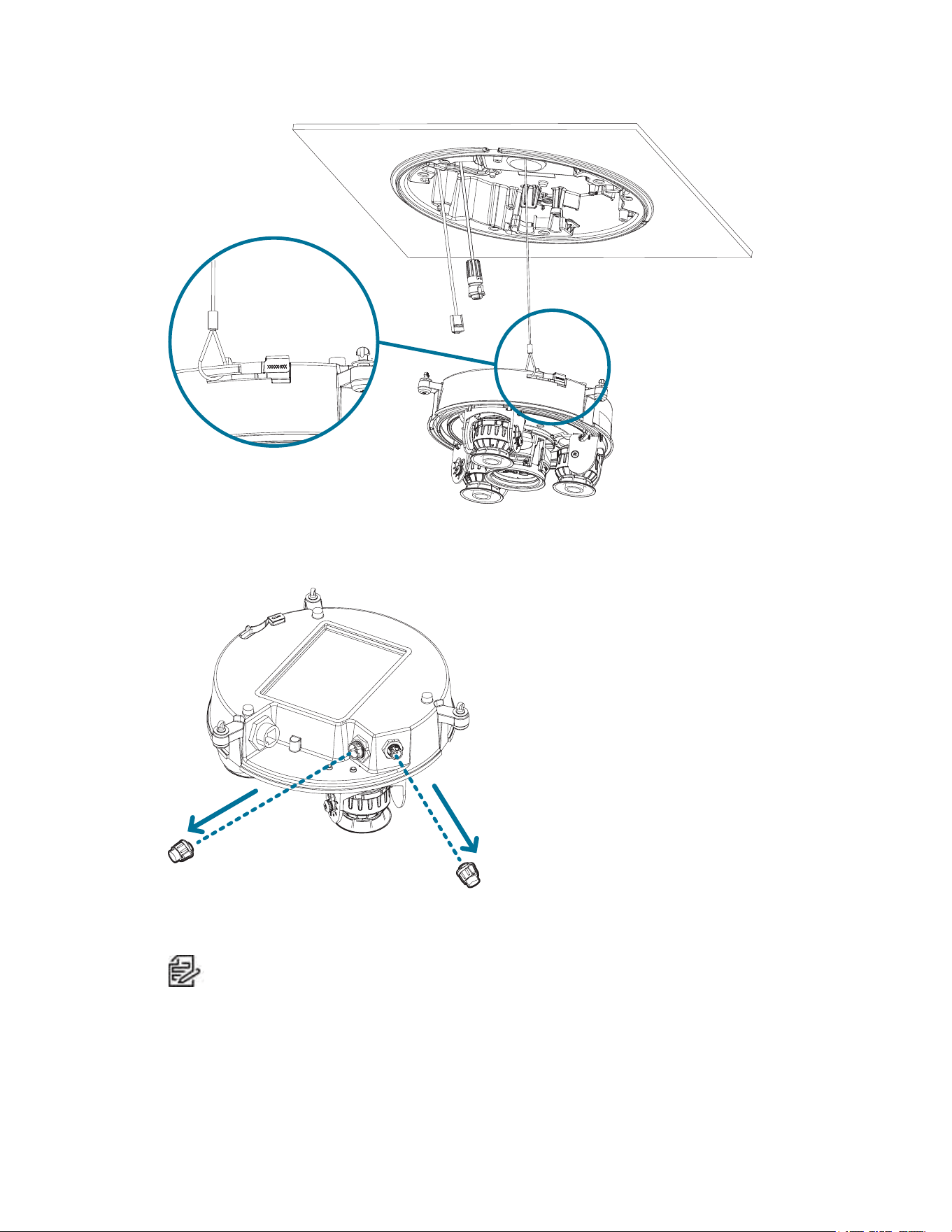
3. Connect the safety lanyard from the mounting adapter to the lanyard anchor on the camera base.
4. Tighten the cable glands around the cables.
Sarix® Multi Pro Camera Installation Manual
C6715M | 01/24/22
23
5. Remove the connector covers from the external power/audio/digital I/O connector and the optional
IR illuminator connector.
6. Connect the network cable to the Ethernet port (a) and the external power/audio/digital I/O cable to
its connector (b). Secure the connections by turning them clockwise (c).
Note: If installing the optional ferrite bead accessory, clamp it around the aux power cable
after connecting the cable.
The Link LED will turn on once a network link has been established.
7. Check that the Connection Status LED indicator indicates the correct state. For more information,
see Connection Status LED Indicator.
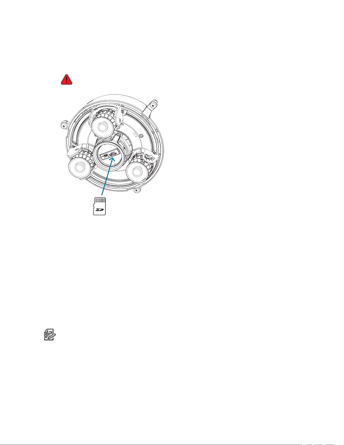
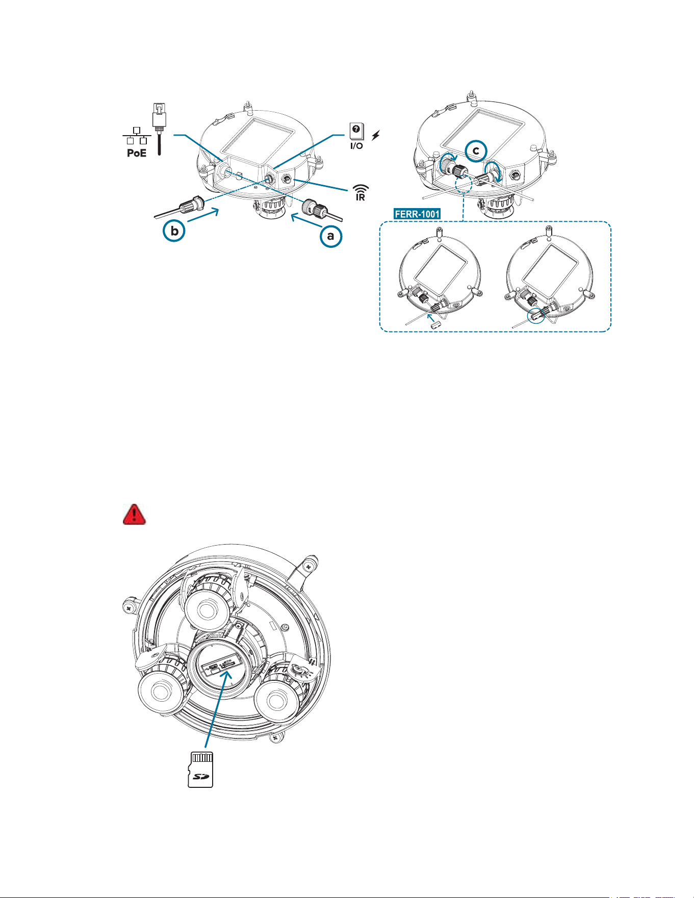
(Optional) Configuring microSD Card Storage
To use the camera's SD card storage feature, you must insert a microSD card into the card slot.

Sarix® Multi Pro Camera Installation Manual
C6715M | 01/24/22
24
It is recommended that the microSD card have a write speed of class 10 or better. If the microSD card does
not meet the recommended write speed, the recording performance may suffer and result in the loss of
frames or footage.
1. Insert a microSD card into the camera.
Insertion of the microSD card is spring loaded. Do not force the microSD card into the
camera or you may damage the card and the camera.
2. Access the camera’s web interface to enable the onboard storage feature. For more information, see
the Pelco Sarix Multi Pro Camera Operations Manual.
Initializing a Camera Username and Password
Important: You must create a user with administrator privileges before the camera is operational.
If the camera is in the factory default state, you will be redirected to the New User page to create an
administrator user:
1. Enter a new User Name or keep the default administrator name.
2. Enter a new Password for the user. It is recommended to use a secure and complex password.
3. Confirm the new password.
4. For the first user, Administrator must be selected in the Security Group drop-down menu.
5. Click Apply. After creating the user, you will be asked to login.
Tip: If you are connecting your Pelco camera to a 3rd party VMS, you will need to set up the first
user through the camera's Web Interface or Camera Configuration Tool before you connect to the 3rd
party VMS.
Assigning an IP Address
The device automatically obtains an IP address when it is connected to a network.
Sarix® Multi Pro Camera Installation Manual
C6715M | 01/24/22
25
Note: If the device cannot obtain an IP address from a DHCP server, it will use Zero Configuration
Networking (Zeroconf) to choose an IP address. When set using Zeroconf, the IP address is in the
169.254.0.0/16 subnet.
The IP address settings can be changed using one of the following methods:
l Device's web browser interface: http://<camera IP address>/.
l Network Video Management software application (for example, the Pelco VideoXpert software).
l ARP/Ping method. For more information, see Setting the IP Address Using the ARP/Ping Method.
Accessing the Live VideoStream
Live video stream can be viewed using one of the following methods:
l Web browser interface: http://< camera IP address>/.
l Network Video Management software application (for example, the Pelco VideoXpert software).
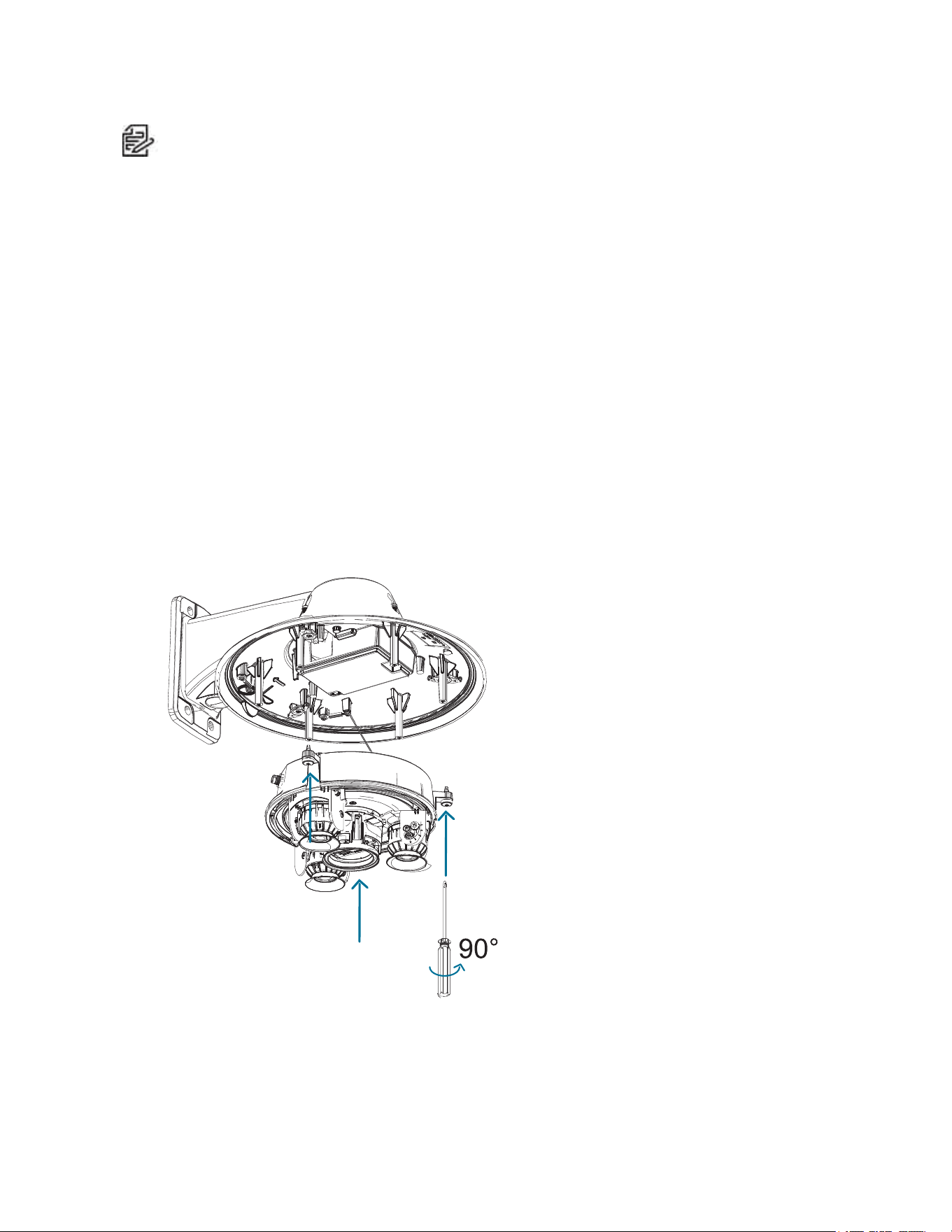
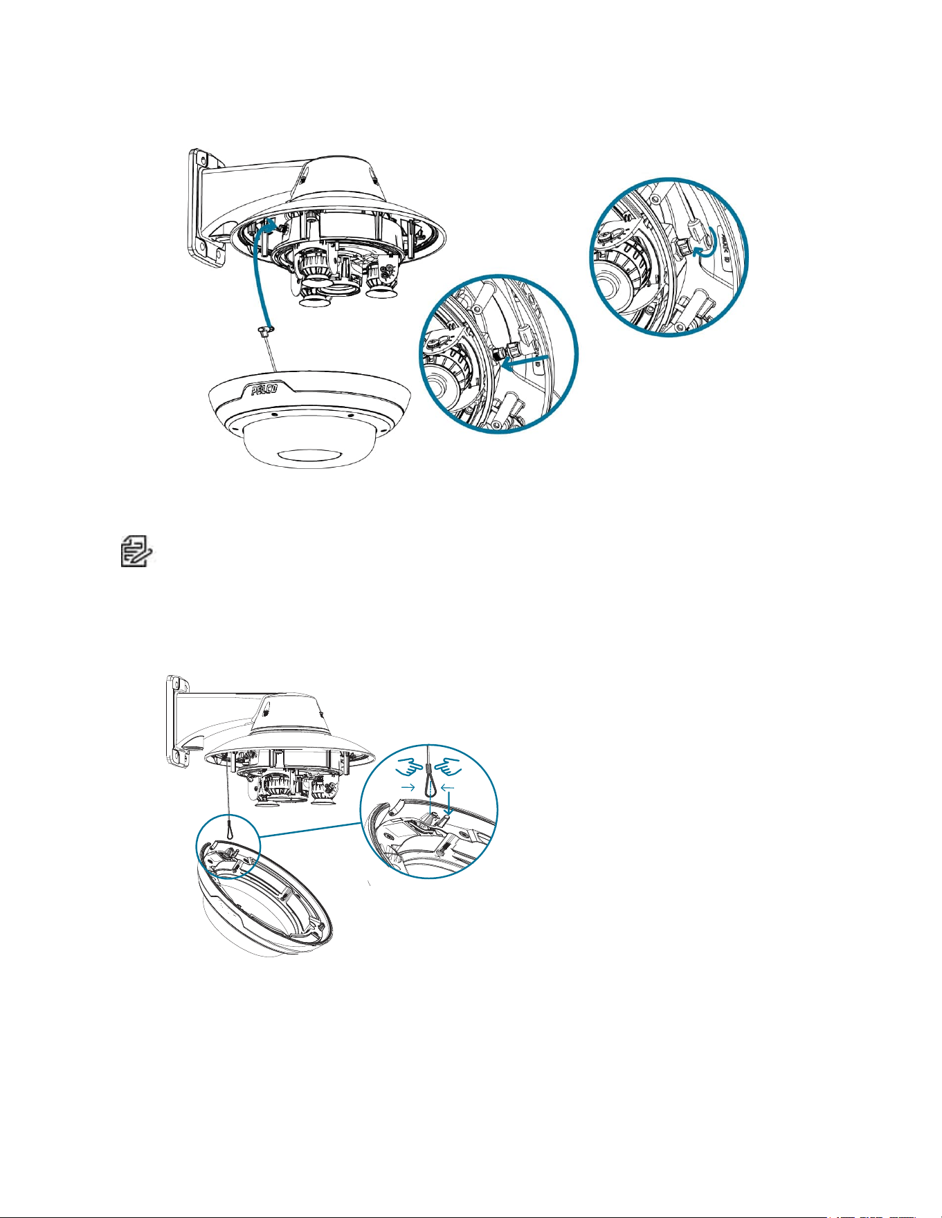
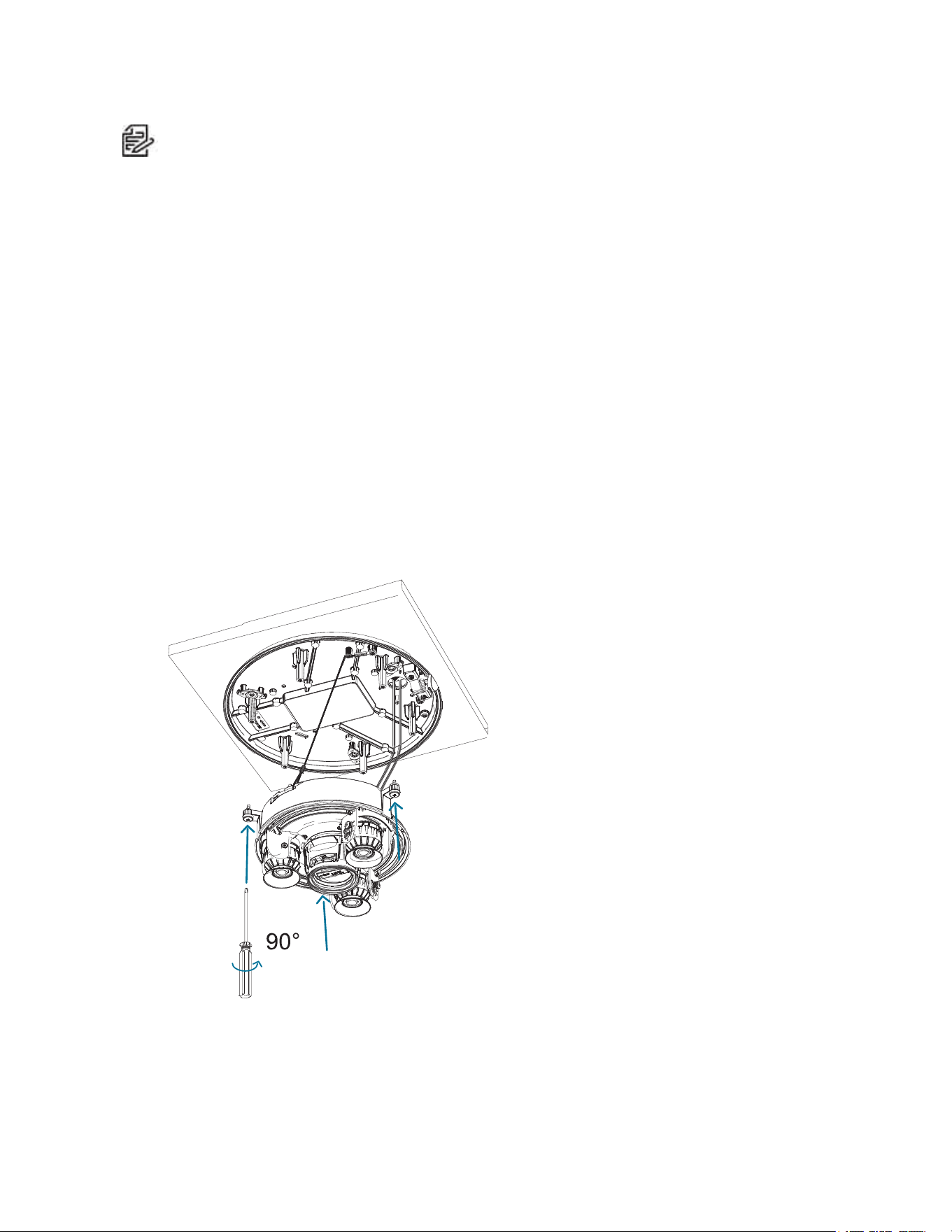
Installing the Sarix Multi Pro Camera Base to a Pendant Mount
After the cable connections have been made, mount the Sarix Multi Pro camera base into the pendant
mount adapter.
1. (Recommended) Attach a safety lanyard from the pendant mount adapter to the lanyard anchor on
the camera base to prevent the camera from falling. See Connecting Cables.
2. Push the camera base into the pendant adapter so that the quick install fasteners in the camera
base align with the screw holes in the pendant adapter.
3. Use a screwdriver to turn the 3 setscrews clockwise by 90° and secure the camera to the pendant
mount adapter.
Sarix® Multi Pro Camera Installation Manual
C6715M | 01/24/22
26
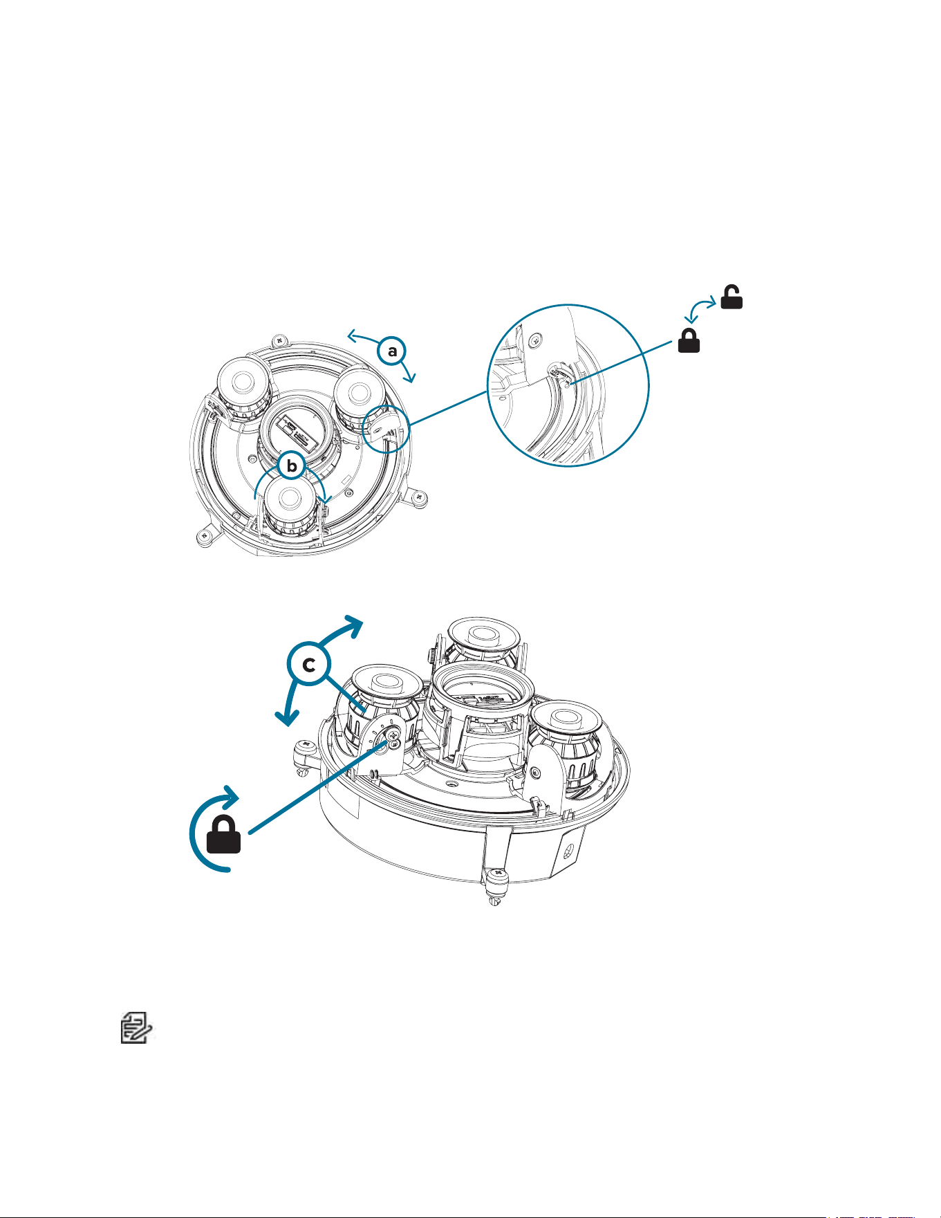
Aiming the Sarix Multi Pro Camera
Reference the camera's live stream as you aim the camera.
1. To aim the camera, adjust each of the available camera heads as required:
a. Unlock the rail release tab to move the camera head from side to side. Lock the rail release tab
when the camera head is in the desired position.
b. Rotate the azimuth control ring to set the image in the correct rotation.
c. Loosen the tilt lock screws to tilt each camera head up and down. Tighten the tilt lock screws
when the camera is tilted in the correct angle.
2. In the camera web browser interface, adjust the camera’s Image and Display settings to achieve the
desired image parameters and position.
(Optional) Installing the IR Illuminator Ring
Note: The optional IR illuminator ring (IMD1-IR) is compatible with the pendant and surface mount
installations of the Sarix Multi Pro camera. The hot-pluggable IR illuminator ring must be mounted in
an outdoor dome cover (IMD1-SPLD1 or IMD1-SPLD0).

Sarix® Multi Pro Camera Installation Manual
C6715M | 01/24/22
27
After the camera has been mounted into the mounting adapter, install the IR illuminator ring with the Sarix
Multi Pro camera base:
1. Mount the IR illuminator ring into the dome cover (IMD1-SPLD1 or IMD1-SPLD0):
a. Insert the IR ring into the dome cover so that the orange arrow on the IR ring aligns with the
orange tab on the dome cover.
b. Use a screwdriver to secure the IRring to the dome cover by tightening the 6 setscrews.
2. (Recommended) Attach a safety lanyard from the mounted camera to the lanyard anchor on the
dome cover to prevent the cover from falling. See Installing the Pendant Mount Dome Cover.
3. Push the IR ring cable onto IR connector on the camera base and turn the connector clockwise to
Sarix® Multi Pro Camera Installation Manual
C6715M | 01/24/22
28
secure the connection.
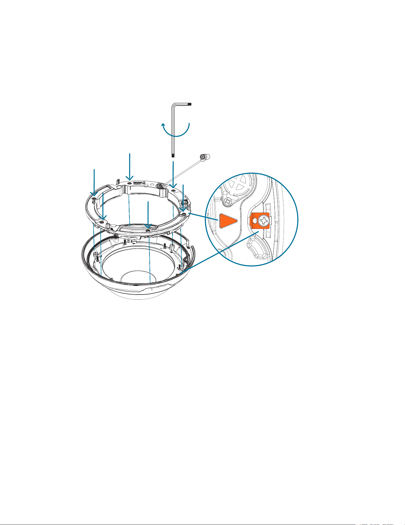
Installing the Pendant Mount Dome Cover
Note: Be careful not to scratch or touch the dome bubble. The resulting marks or fingerprints may
affect the overall image quality. Keep the protective covers on the outside of the dome bubble until
the installation is complete.
1. (Recommended) Attach a safety lanyard from the pendant mount adapter to the lanyard anchor on
the dome cover to prevent the dome cover from falling.
2. Align the notches on the dome cover with the release tab on the pendant mount adapter. The dome
cover should be flush against the pendant mount adapter.
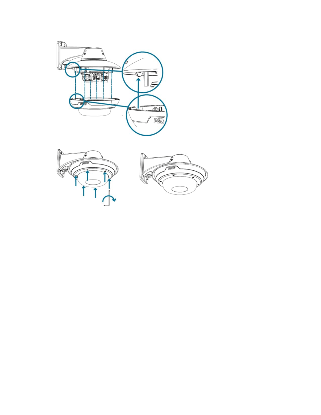
Sarix® Multi Pro Camera Installation Manual
C6715M | 01/24/22
29
3. Tighten the setscrews to secure the dome cover in place.

Sarix® Multi Pro Camera Installation Manual
C6715M | 01/24/22
30
Surface Mount Installation
Camera Package Contents
The Sarix Multi Pro camera has a variety of different mounting, dome cover, camera and accessory
options. The components for each Sarix Multi Pro camera will arrive in a camera package, a dome cover
package, a mounting adapter package, a mount package (for pendant mount cameras), and a metal ceiling
panel package (for in-ceiling cameras).
Ensure the camera package contains the following:
l Pelco Sarix Multi Pro Camera module. A 3- or 4-sensor camera module with 3 MP, 5 MP, or 4K (8
MP) resolution per sensor.
l Audio, external power, and I/O pigtail cable connector
l RJ45 CAT5E plugs (x2)
l RJ45 connector waterproof gland
Ensure the Surface mount adapter package contains the following:
l Surface mount adapter (IMD1-SMT)
l Installation instructions sheet
l Mounting template sticker
Ensure the dome cover package contains the following:
l Clear or smoked dome bubble and cover (IMD1-INCLD1 or IMD1-SPLD0)
If you are installing the camera with the optional IR illuminator, ensure the package includes the following:
l IR illuminator ring (IMD1-IR)
Surface Mount Installation Steps
Complete the following sections to install the device.
Installing the Surface Mount Adapter
Follow this procedure to route camera cables and install the surface mount adapter (IMD1-SMT) to the
mounting surface.
1. Determine where the cables will enter the camera. The surface mount adapter has two cable entry
holes: one on the side and one on the bottom of the mounting adapter.
l Use the supplied closure plug to fill the unused cable entry hole.
l When installing outdoors, wrap the threads of the closure plug with plumber's tape to create a
watertight seal.
Note:
Only use vandal-resistant conduits to route cables into the mounting adapter. Vandal-
resistant conduits will protect the cables and compliment the camera's vandal-resistant
design.
Note:
When installing the
Sarix Multi Pro
surface mount camera outdoors, ensure the conduit
and its fitting are designed for outdoor use and have a suitable IP rating. Always apply silicone
sealant to seal the cable entry hole and prevent excessive moisture from entering the camera.
2. If you are using the rear cable entry hole:
Sarix® Multi Pro Camera Installation Manual
C6715M | 01/24/22
31
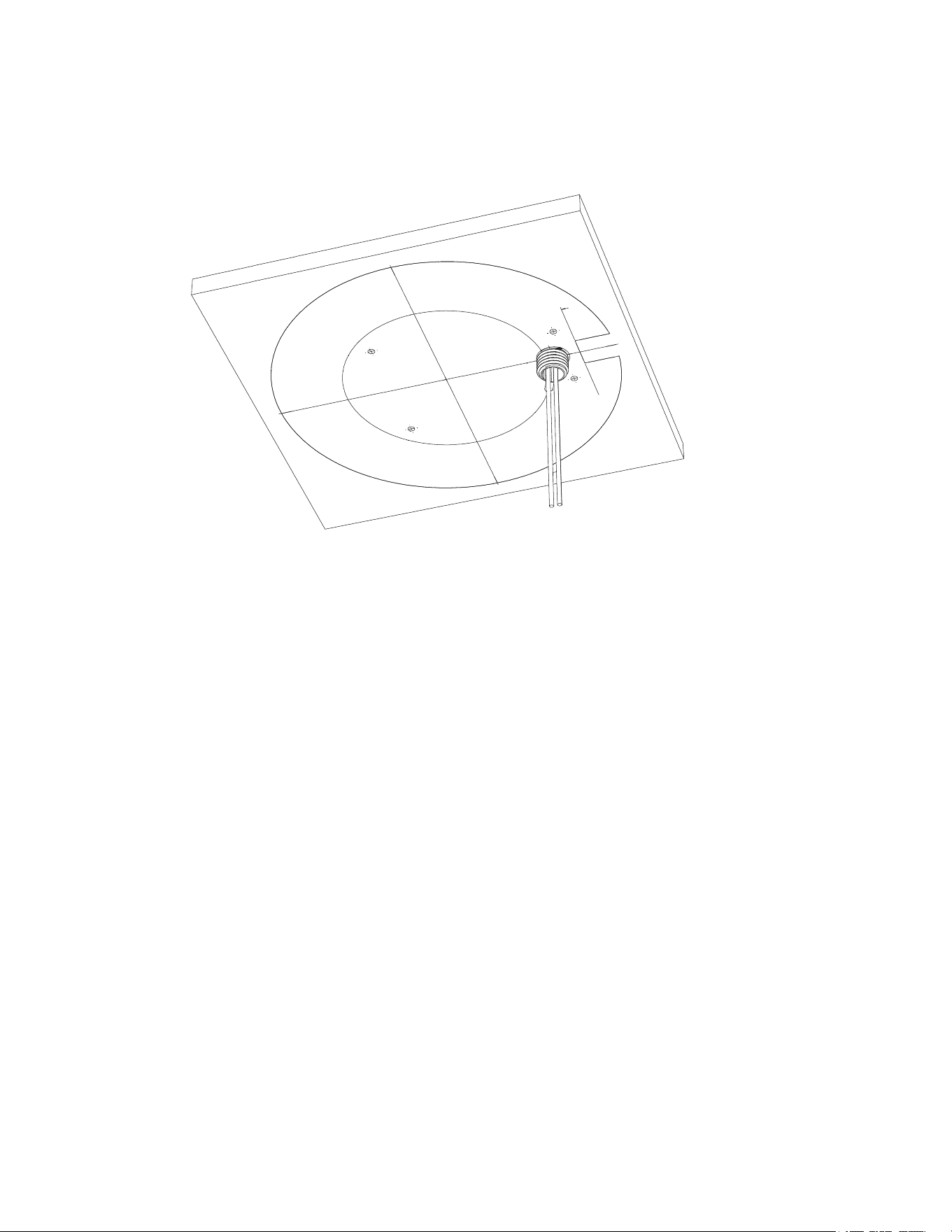
a. Use the supplied mounting template to determine the cable entry location. Drill a hole in the
mounting surface and route the conduit and cables through the hole. Install the conduit and its
fitting as instructed by the manufacturer.
b. Drill 4 mounting holes as marked on the mounting template.
c. Pull the cables through the rear cable entry hole on the surface mount adapter.
d. Use a screwdriver to secure the mounting adapter to the mounting surface with the 4 mounting
screws.
Sarix® Multi Pro Camera Installation Manual
C6715M | 01/24/22
32
e. Secure the conduit to the surface mount adapter with the lock nut.
Note:
If installing outdoors, apply silicone sealant around the edge of the surface mount
adapter that is connected to the mounting surface.
3. If you are using the side cable entry hole:
Note:
If you are installing the camera outdoors on a vertical surface, the side cable entry hole
and conduit connector must face downwards to prevent excessive moisture from entering the
camera.
a. Use the supplied mounting template to determine the cable entry location. Run the cables and
conduit to the side opening as marked on the mounting template. Install the conduit and its
fitting as instructed by the manufacturer.
Sarix® Multi Pro Camera Installation Manual
C6715M | 01/24/22
33
b. Drill 4 mounting holes as marked on the mounting template.
c. Pull the cables through the side cable entry hole on the surface mount adapter.
d. Use a screwdriver to secure the mounting adapter to the mounting surface with the 4 mounting
screws.
e. Secure the conduit to the surface mount adapter with the conduit clamp.
Sarix® Multi Pro Camera Installation Manual
C6715M | 01/24/22
34
Note:
If installing outdoors, apply silicone sealant around the edge of the surface mount
adapter that is connected to the mounting surface.

Sarix® Multi Pro Camera Installation Manual
C6715M | 01/24/22
35
Connecting Cables
Refer to the diagrams in the Overview section for the location of the different connectors.
To connect the cables required for proper operation, complete the following:
1. Feed the network cable through the gland cap and cable gland. Crimp the RJ-45 cable connector
(supplied) to the end of your network cable.
The network cable connection can also be used to supply power to the camera using Power over
Ethernet (PoE). If using PoE, connect a PoE compliant injector or switch to the Ethernet network
cable with the output rated:
l With IR Ring: 60W PoE mid-span injector (PD-9501GR/AC-NA-MSI and include POE190-BT).
Alternatively, connect to a Cisco® UPoE capable switch, supporting 60W over 4 pairs. Note
that the Cisco switch must be configured with the Force Four Pair option enabled.
l Without IR Ring: Power over Ethernet (PoE) Plus, PD-9001GR/AT/AC-MSI, IEEE 802.3at
Class 4 — Connect a PoE Plus compliant injector or switch (e.g. POE430-AT, POE1236-AT, or
POE2436-AT).
Note: When on UPoE and without an IR ring, the Sarix Multi Pro will continue to request
60W power on startup, as the IR ring is a hot-pluggable add-on accessory. If the IRring
accessory will never be used, the recommendation is to limit the available power to PoE
plus equivalent on the Cisco switch settings.
2. Connect the following optional connections to the supplied pigtail I/O connector. See Connecting to
Power, Audio, and External Devices for more information on the different connections.
a. If external input or output devices are part of the installation (for example: door contacts,
relays, etc.), wire those devices to the pigtail connector.
b. If an external microphone or speaker is required, connect the devices to the pigtail connector.
c. If external power is required, connect an external "Class 2" or "LPS" or "Limited Power Source"
to the pigtail connector with output rated:
Sarix® Multi Pro Camera Installation Manual
C6715M | 01/24/22
36
l With IR Ring: 24 VAC ± 10%, 74 VA minimum, or 24 VDC ± 10%, 52 W minimum.
l Without IR Ring: 24 VAC ± 10%, 37 VA minimum, or 24 VDC ± 10%, 26 W minimum.
3. Connect the safety lanyard from the mounting adapter to the lanyard anchor on the camera base.
4. Tighten the cable glands around the cables.

Sarix® Multi Pro Camera Installation Manual
C6715M | 01/24/22
37
5. Remove the connector covers from the external power/audio/digital I/O connector and the optional
IR illuminator connector.
6. Connect the network cable to the Ethernet port (a) and the external power/audio/digital I/O cable to
its connector (b). Secure the connections by turning them clockwise (c).
Note: If installing the optional ferrite bead accessory, clamp it around the aux power cable
after connecting the cable.
The Link LED will turn on once a network link has been established.
7. Check that the Connection Status LED indicator indicates the correct state. For more information,
see Connection Status LED Indicator.
(Optional) Configuring microSD Card Storage
To use the camera's SD card storage feature, you must insert a microSD card into the card slot.
Sarix® Multi Pro Camera Installation Manual
C6715M | 01/24/22
38
It is recommended that the microSD card have a write speed of class 10 or better. If the microSD card does
not meet the recommended write speed, the recording performance may suffer and result in the loss of
frames or footage.
1. Insert a microSD card into the camera.
Insertion of the microSD card is spring loaded. Do not force the microSD card into the
camera or you may damage the card and the camera.
2. Access the camera’s web interface to enable the onboard storage feature. For more information, see
the Pelco Sarix Multi Pro Camera Operations Manual.
Initializing a Camera Username and Password
Important: You must create a user with administrator privileges before the camera is operational.
If the camera is in the factory default state, you will be redirected to the New User page to create an
administrator user:
1. Enter a new User Name or keep the default administrator name.
2. Enter a new Password for the user. It is recommended to use a secure and complex password.
3. Confirm the new password.
4. For the first user, Administrator must be selected in the Security Group drop-down menu.
5. Click Apply. After creating the user, you will be asked to login.
Tip: If you are connecting your Pelco camera to a 3rd party VMS, you will need to set up the first
user through the camera's Web Interface or Camera Configuration Tool before you connect to the 3rd
party VMS.
Assigning an IP Address
The device automatically obtains an IP address when it is connected to a network.
Sarix® Multi Pro Camera Installation Manual
C6715M | 01/24/22
39
Note: If the device cannot obtain an IP address from a DHCP server, it will use Zero Configuration
Networking (Zeroconf) to choose an IP address. When set using Zeroconf, the IP address is in the
169.254.0.0/16 subnet.
The IP address settings can be changed using one of the following methods:
l Device's web browser interface: http://<camera IP address>/.
l Network Video Management software application (for example, the Pelco VideoXpert software).
l ARP/Ping method. For more information, see Setting the IP Address Using the ARP/Ping Method.
Accessing the Live VideoStream
Live video stream can be viewed using one of the following methods:
l Web browser interface: http://< camera IP address>/.
l Network Video Management software application (for example, the Pelco VideoXpert software).
Installing the Sarix Multi Pro Camera Base to a Surface Mount
After the cable connections have been made, mount the Sarix Multi Pro camera base into the surface
mount adapter.
1. (Recommended) Attach a safety lanyard from the surface mount adapter to the lanyard anchor on
the camera base to prevent the camera from falling. See Connecting Cables.
2. Push the camera base into the surface mount adapter so that the 3 setscrews in the camera base
align with the screw holes in the surface mount adapter.
3. Use a screwdriver to turn the 3 setscrews clockwise by 90° and secure the camera to the surface
mount adapter.

Sarix® Multi Pro Camera Installation Manual
C6715M | 01/24/22
40
Aiming the Sarix Multi Pro Camera
Reference the camera's live stream as you aim the camera.
1. To aim the camera, adjust each of the available camera heads as required:
a. Unlock the rail release tab to move the camera head from side to side. Lock the rail release tab
when the camera head is in the desired position.
b. Rotate the azimuth control ring to set the image in the correct rotation.
c. Loosen the tilt lock screws to tilt each camera head up and down. Tighten the tilt lock screws
when the camera is tilted in the correct angle.
2. In the camera web browser interface, adjust the camera’s Image and Display settings to achieve the
desired image parameters and position.
(Optional) Installing the IR Illuminator Ring
Note: The optional IR illuminator ring (IMD1-IR) is compatible with the pendant and surface mount
installations of the Sarix Multi Pro camera. The hot-pluggable IR illuminator ring must be mounted in
an outdoor dome cover (IMD1-SPLD1 or IMD1-SPLD0).
Sarix® Multi Pro Camera Installation Manual
C6715M | 01/24/22
41
After the camera has been mounted into the mounting adapter, install the IR illuminator ring with the Sarix
Multi Pro camera base:
1. Mount the IR illuminator ring into the dome cover (IMD1-SPLD1 or IMD1-SPLD0):
a. Insert the IR ring into the dome cover so that the orange arrow on the IR ring aligns with the
orange tab on the dome cover.
b. Use a screwdriver to secure the IRring to the dome cover by tightening the 6 setscrews.
2. (Recommended) Attach a safety lanyard from the mounted camera to the lanyard anchor on the
dome cover to prevent the cover from falling. See Installing the Surface Mount Dome Cover.
3. Push the IR ring cable onto IR connector on the camera base and turn the connector clockwise to
Sarix® Multi Pro Camera Installation Manual
C6715M | 01/24/22
42
secure the connection.
Installing the Surface Mount Dome Cover
Note: Be careful not to scratch or touch the dome bubble. The resulting marks or fingerprints may
affect the overall image quality. Keep the protective covers on the outside of the dome bubble until
the installation is complete.
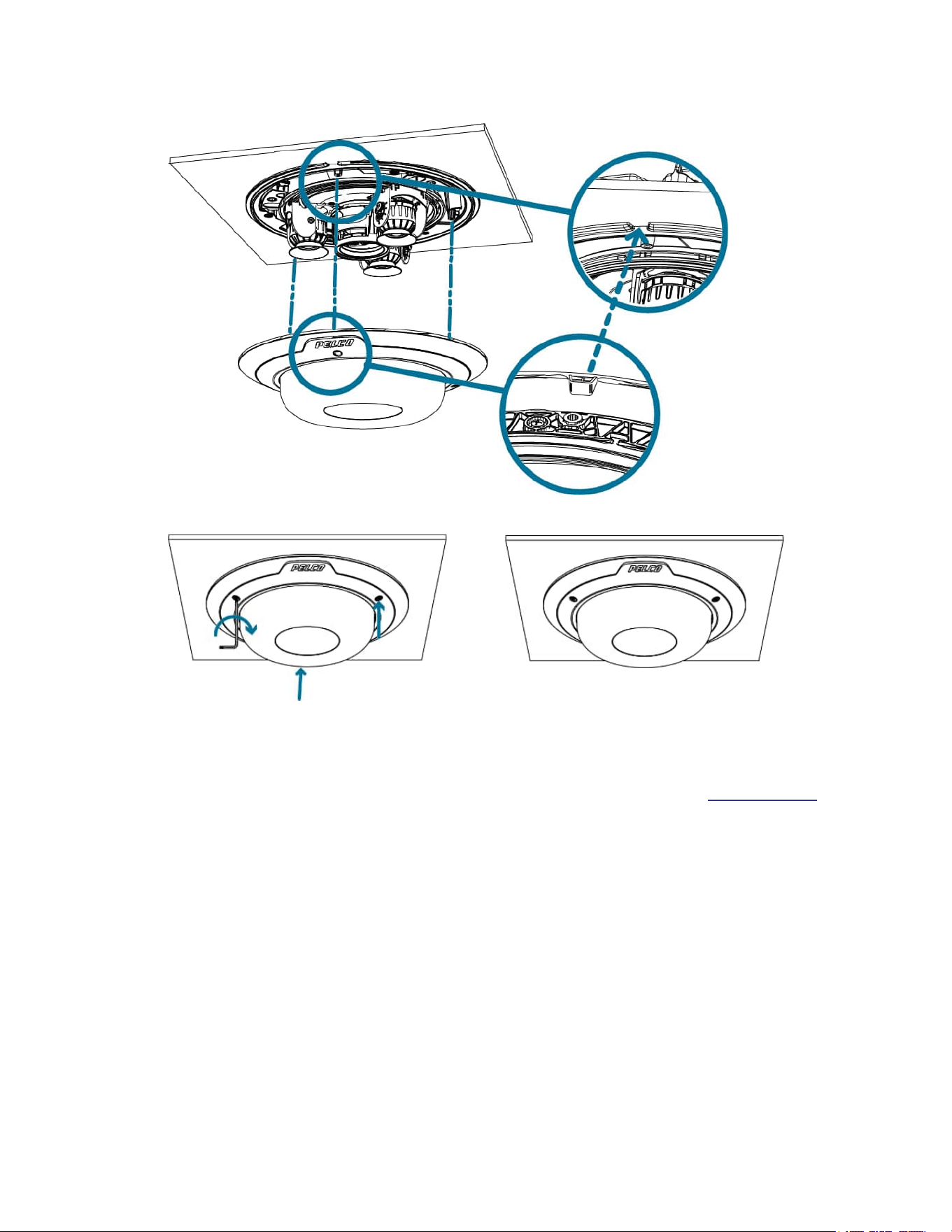
1. (Recommended) Attach a safety lanyard from the surface mount adapter to the lanyard anchor on
the dome cover to prevent the dome cover from falling.
2. Align the inverted tab on the dome cover with the tab on the surface mount adapter. The dome cover
should be flush against the surface mount adapter.
Sarix® Multi Pro Camera Installation Manual
C6715M | 01/24/22
43
3. Tighten the setscrews to secure the dome cover in place.

Sarix® Multi Pro Camera Installation Manual
C6715M | 01/24/22
44
In-Ceiling Mount Installation
Camera Package Contents
The Sarix Multi Pro camera has a variety of different mounting, dome cover, camera and accessory
options. The components for each Sarix Multi Pro camera will arrive in a camera package, a dome cover
package, a mounting adapter package, a mount package (for pendant mount cameras), and a metal ceiling
panel package (for in-ceiling cameras).
Ensure the camera package contains the following:
l Pelco Sarix Multi Pro Camera module. A 3- or 4-sensor camera module with 3 MP, 5 MP, or 4K (8
MP) resolution per sensor.
l Audio, external power, and I/O pigtail cable connector
l RJ45 CAT5E plugs (x2)
l RJ45 connector waterproof gland
Ensure the In-Ceiling mount adapter package contains the following:
l In-ceiling mount adapter (IMD1-INC)
l Cable entry cover
l Installation instructions sheet
l Mounting template sticker
Ensure the dome cover package contains the following:
l Clear or smoked dome bubble and cover (IMD1-INCLD1 or IMD1-INCLD0)
If you are installing the in-ceiling camera with the metal ceiling panel, ensure the package includes the
following:
l Metal ceiling panel (CLPNL-1001)
In-Ceiling Mount Installation Steps
Complete the following sections to install the device.
Preparing the Camera for In-Ceiling Installation
Before starting the installation, prepare the in-ceiling adapter for installation:
1. If you are planning to use onboard storage, insert a microSD card into the SD card slot on the Sarix
Multi Pro camera. For more information, see (Optional) Configuring microSD Card Storage.
2. Use a screwdriver to push each of the clamps into their top positions and ensure their springs are
fully compressed. In one smooth motion, push each clamp up (a), clockwise (b), up again (c), and
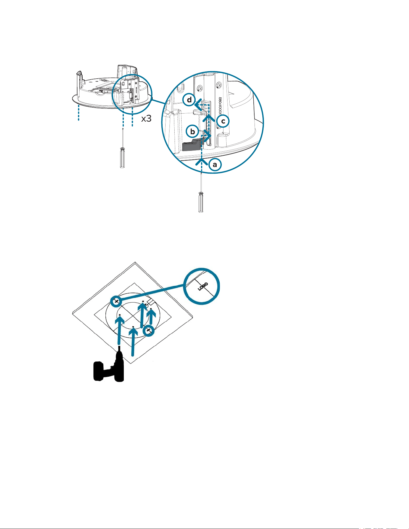
Sarix® Multi Pro Camera Installation Manual
C6715M | 01/24/22
45
then counter-clockwise (d).
(Optional) Cutting the Mounting Hole for the In-Ceiling Mount Adapter
This procedure is not required if you are planning to install the camera with a metal ceiling panel (CLPNL-
1001).
1. Use the mounting template to cut a hole in the mounting surface.
2. Remove the mounting template and pull the required cables through the mounting hole. If you are
using a conduit pipe to route the cables, see (Optional) Attaching the Conduit Cable Entry Cover for
Plenum Installations.
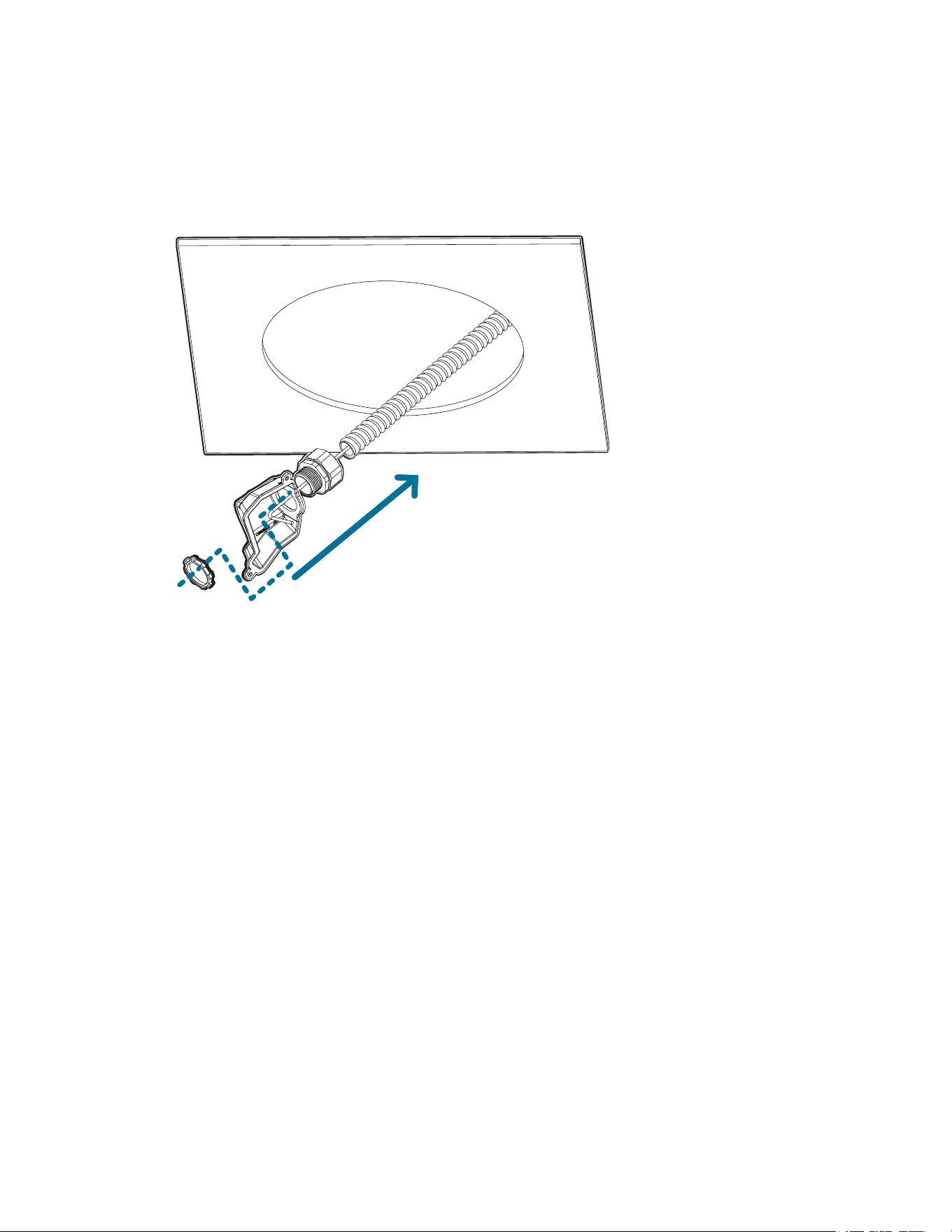
(Optional) Attaching the Conduit Cable Entry Cover for Plenum Installations
If you are installing the Sarix Multi Pro camera into a plenum space, use a conduit pipe and the cable entry
cover to route the cables through the in-ceiling adapter.
Sarix® Multi Pro Camera Installation Manual
C6715M | 01/24/22
46
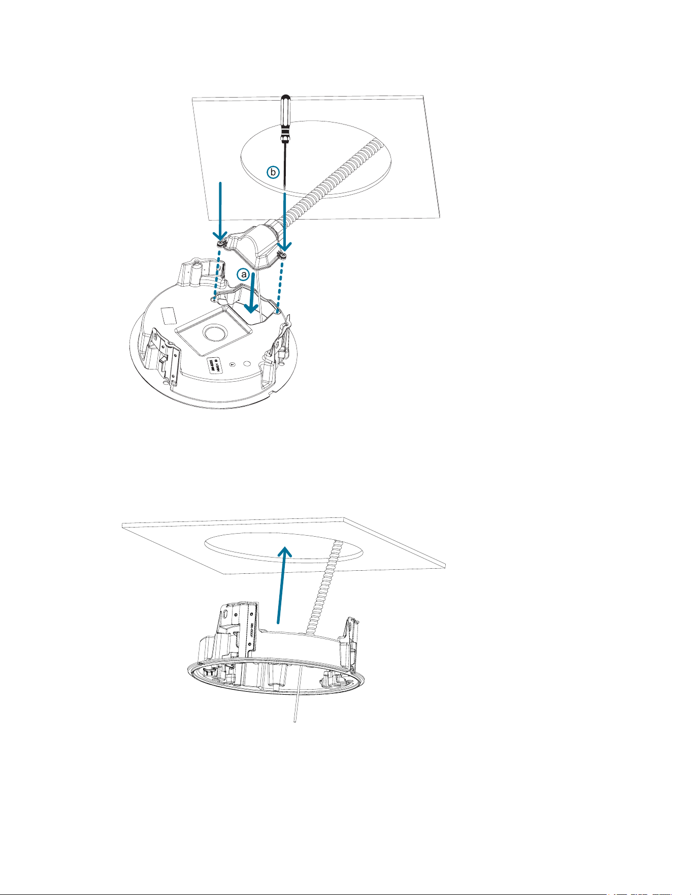
1. Route the required cables through a conduit pipe at the installation location.
2. Attach a conduit connector to the cable entry cover. Install the conduit and its fitting as instructed by
the manufacturer. Make sure the conduit is securely fastened to the cable entry cover.
3. Pull the required cables through the conduit and cable entry cover, then through the cable entry hole
in the in-ceiling adapter (a). Fasten the cable entry cover over the cable entry hole in the in-ceiling
adapter using the provided setscrews (b).
Sarix® Multi Pro Camera Installation Manual
C6715M | 01/24/22
47
Installing the In-Ceiling Mounting Adapter
Use the following procedure to mount the in-ceiling adapter into a plenum space or the metal ceiling panel
(CLPNL-1001).
1. After routing the cables through the in-ceiling adapter, push the adapter into the hole in the mounting
surface.
2. Use a screwdriver to lower each of the clamps from their top positions and secure the adapter to the
mounting surface. In one smooth motion, move each clamp clockwise (a), and then down to its
Sarix® Multi Pro Camera Installation Manual
C6715M | 01/24/22
48
secure position (b).
Sarix® Multi Pro Camera Installation Manual
C6715M | 01/24/22
49
Connecting Cables
Refer to the diagrams in the Overview section for the location of the different connectors.
To connect the cables required for proper operation, complete the following:
1. Crimp the RJ-45 cable connector (supplied) to the end of your network cable.
The network cable connection can also be used to supply power to the camera using Power over
Ethernet (PoE). If using PoE, connect a PoE compliant injector or switch to the Ethernet network
cable with the output rated:
l 25.5 W PoE+, IEEE802.3at Type 2 PoE+.
2. Connect the following optional connections to the supplied pigtail I/O connector. See Connecting to
Power, Audio, and External Devices for more information on the different connections.
a. If external input or output devices are part of the installation (for example: door contacts,
relays, etc.), wire those devices to the pigtail connector.
b. If an external microphone or speaker is required, connect the devices to the pigtail connector.
c. If external power is required, connect an external "Class 2" or "LPS" or "Limited Power Source"
to the pigtail connector with output rated:
l 24 VAC ± 10%, 37 VA minimum, or 24 VDC ± 10%, 26 W minimum.
3. Connect the safety lanyard from the mounting adapter to the lanyard anchor on the camera base.
Sarix® Multi Pro Camera Installation Manual
C6715M | 01/24/22
50
4. Tighten the cable glands around the cables.
5. Remove the connector covers from the external power/audio/digital I/O connector and the optional
IR illuminator connector.
6. Connect the network cable to the Ethernet port (a) and the external power/audio/digital I/O cable to
its connector (b). Secure the connections by turning them clockwise (c).
Note: If installing the optional ferrite bead accessory, clamp it around the aux power cable
after connecting the cable.
Sarix® Multi Pro Camera Installation Manual
C6715M | 01/24/22
51
The Link LED will turn on once a network link has been established.
7. Check that the Connection Status LED indicator indicates the correct state. For more information,
see Connection Status LED Indicator.
(Optional) Configuring microSD Card Storage
To use the camera's SD card storage feature, you must insert a microSD card into the card slot.
It is recommended that the microSD card have a write speed of class 10 or better. If the microSD card does
not meet the recommended write speed, the recording performance may suffer and result in the loss of
frames or footage.
1. Insert a microSD card into the camera.
Insertion of the microSD card is spring loaded. Do not force the microSD card into the
camera or you may damage the card and the camera.

Sarix® Multi Pro Camera Installation Manual
C6715M | 01/24/22
52
2. Access the camera’s web interface to enable the onboard storage feature. For more information, see
the Pelco Sarix Multi Pro Camera Operations Manual.
Initializing a Camera Username and Password
Important: You must create a user with administrator privileges before the camera is operational.
If the camera is in the factory default state, you will be redirected to the New User page to create an
administrator user:
1. Enter a new User Name or keep the default administrator name.
2. Enter a new Password for the user. It is recommended to use a secure and complex password.
3. Confirm the new password.
4. For the first user, Administrator must be selected in the Security Group drop-down menu.
5. Click Apply. After creating the user, you will be asked to login.
Tip: If you are connecting your Pelco camera to a 3rd party VMS, you will need to set up the first
user through the camera's Web Interface or Camera Configuration Tool before you connect to the 3rd
party VMS.
Assigning an IP Address
The device automatically obtains an IP address when it is connected to a network.
Note: If the device cannot obtain an IP address from a DHCP server, it will use Zero Configuration
Networking (Zeroconf) to choose an IP address. When set using Zeroconf, the IP address is in the
169.254.0.0/16 subnet.
The IP address settings can be changed using one of the following methods:
l Device's web browser interface: http://<camera IP address>/.
l Network Video Management software application (for example, the Pelco VideoXpert software).
l ARP/Ping method. For more information, see Setting the IP Address Using the ARP/Ping Method.
Accessing the Live VideoStream
Live video stream can be viewed using one of the following methods:
l Web browser interface: http://< camera IP address>/.
l Network Video Management software application (for example, the Pelco VideoXpert software).
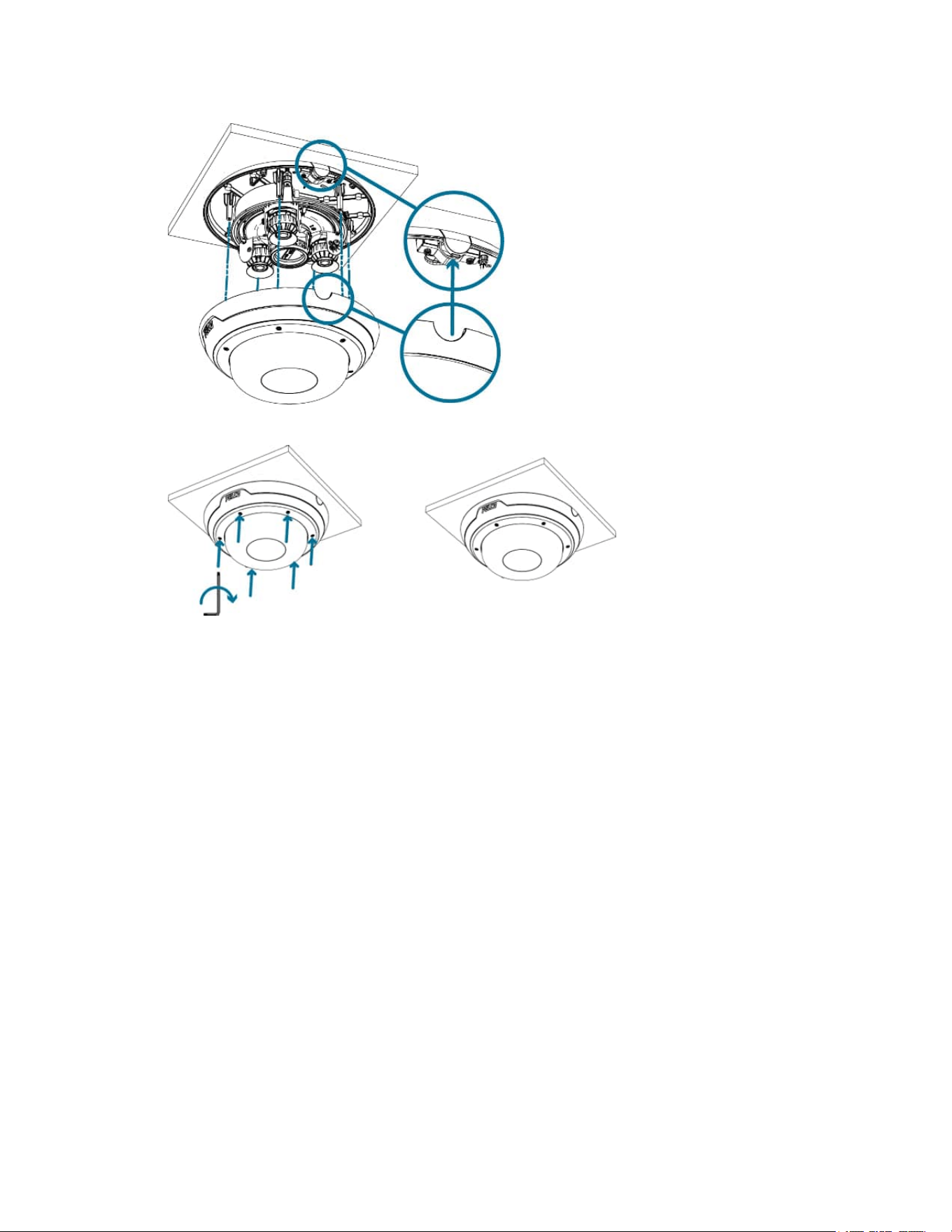
Installing the Sarix Multi Pro Camera Base to an In-Ceiling Mount
After the cable connections have been made, mount the Sarix Multi Pro camera base into the in-ceiling
mount adapter.
1. (Recommended) Attach a safety lanyard from the in-ceiling mount adapter to the lanyard anchor on
the camera base to prevent the camera from falling. See Connecting Cables.
2. Push the camera module into the in-ceiling mounting adapter so that the 3 setscrews pass through
the 3 slots (a). In one smooth motion, push the camera module up through the 3 slots (a), twist
clockwise (b), and push up again so the 3 setscrews are positioned at the 3 screw holes (c).
Sarix® Multi Pro Camera Installation Manual
C6715M | 01/24/22
53
3. Use a screwdriver to turn the 3 setscrews clockwise by 90° and secure the camera into the in-
ceiling mount adapter (d).
Aiming the Sarix Multi Pro Camera
Reference the camera's live stream as you aim the camera.
1. To aim the camera, adjust each of the available camera heads as required:
a. Unlock the rail release tab to move the camera head from side to side. Lock the rail release tab
when the camera head is in the desired position.
b. Rotate the azimuth control ring to set the image in the correct rotation.
c. Loosen the tilt lock screws to tilt each camera head up and down. Tighten the tilt lock screws
Sarix® Multi Pro Camera Installation Manual
C6715M | 01/24/22
54
when the camera is tilted in the correct angle.
2. In the camera web browser interface, adjust the camera’s Image and Display settings to achieve the
desired image parameters and position.
Installing the In-Ceiling Mount Dome Cover
Note: Be careful not to scratch or touch the dome bubble. The resulting marks or fingerprints may
affect the overall image quality. Keep the protective covers on the outside of the dome bubble until
the installation is complete.
1. (Recommended) Attach a safety lanyard from the in-ceiling mount adapter to the lanyard anchor on
the dome cover to prevent the cover from falling.
2. Align the notches on the dome cover with the release tab on the in-ceiling mount adapter. The dome
cover should be flush against the mounting surface.
Sarix® Multi Pro Camera Installation Manual
C6715M | 01/24/22
55
3. Tighten the setscrews to secure the dome cover in place.
For More Information
Additional information about setting up and using the device is available in the following guide:
l Pelco Sarix Multi Pro Camera Operations Manual available on the Pelco website: www.pelco.com.
Sarix® Multi Pro Camera Installation Manual
C6715M | 01/24/22
56
Cable Connections
Connecting to Power, Audio, and External Devices
If PoE is not available, the camera may be powered through the auxiliary power cable using either 24V DC
or 24V AC. The power consumption information is listed in the product specifications.
To power the camera, connect the two power wires to the brown and blue auxiliary power wires. The
connection can be made with either polarity.
This product is intended to be supplied by a UL Listed Power Unit marked “Class 2” or “LPS” or
“Limited Power Source” with output rated:
With IR LEDs: 24V AC ± 10%, 74 VA minimum, or 24 V DC ± 10%, 52 W minimum.
Without IR LEDs: 24V AC ± 10%, 37 VA minimum, or 24 V DC ± 10%, 26 W minimum.
For more information on using PoE to power the camera, see Connecting Cables.
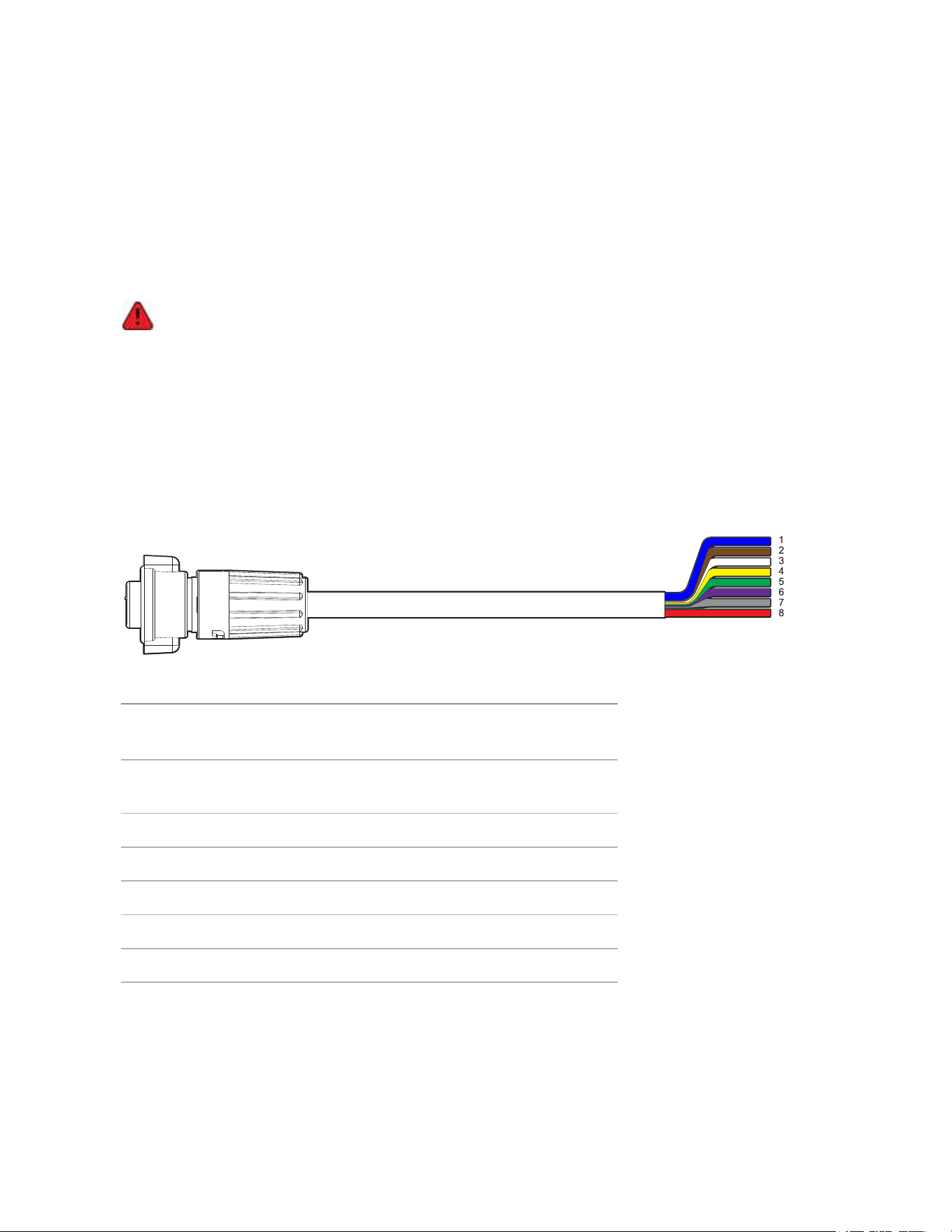
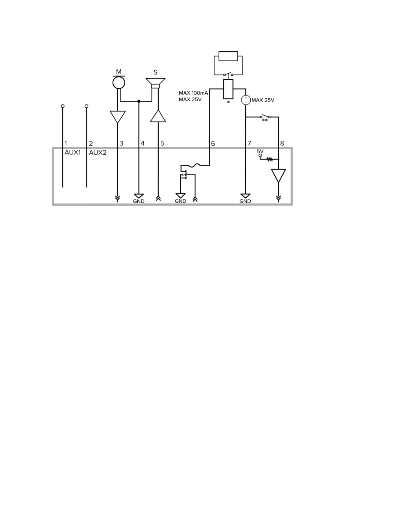
Pigtail Connector and Wires
Power supplies, audio devices, and external devices are connected to the camera through the power,
audio, and I/O pigtail. The following diagram and table shows the I/O, audio, and power pigtail connector
and wires:
Wire Color Description
1 Blue AUX1 Power, accepts either
polarity
2 Brown AUX2 Power, accepts either
polarity
3 White Audio IN
4 Yellow Audio GND
5 Green Audio OUT
6 Purple Relay OUT
7 Gray Relay GND
8 Red Relay IN
Wiring Audio, I/O, and AUX Power
The connections for the I/O, audio, and power wires is shown in the following diagram:
Sarix® Multi Pro Camera Installation Manual
C6715M | 01/24/22
57
1. Brown — AUX1 Auxiliary Power wire, accepts either polarity
2. Blue — AUX2 Auxiliary Power wire, accepts either polarity
3. White — Audio Input (line level)
An external power amplifier should be used when connecting speakers and microphones, as shown
in the diagram.
4. Yellow — Audio Ground return
5. Green — Audio Output (line level)
6. Purple — Relay Output: When active, Output is internally connected with the Ground. Circuit is
open when inactive. Maximum load is 25 V DC, 100 mA.
7. Gray — Relay Ground return
8. Red — Relay Input: To activate, connect the Input to the Ground wire. To deactivate, leave it
disconnected or apply between 3-15 V.
l * — Relay
l ** — Switch
l M — Microphone
l S — Speaker
l AUX1 — Brown Auxiliary Power wire
l AUX2 — Blue Auxiliary Power wire
Focusing the Sarix Multi Pro Camera
Ensure this procedure is performed after the dome cover is installed so you can accommodate for the focus
shift caused by the dome bubble.
Ensure you adjust the focus for each of the camera heads included with your Sarix Multi Pro camera.
In the camera web browser interface, use the camera’s Image and Display settings to focus the camera.

Sarix® Multi Pro Camera Installation Manual
C6715M | 01/24/22
58
1. Click Auto Focus to focus the lens.
2. Use the focus near and far buttons to manually adjust the focus.
Connection Status LED Indicator
Once connected to the network, the green Connection Status LED indicator will display the progress in
connecting to the Network Video Management software.
The following table describes what the LED indicator shows:
Connection State Connection
Status LED
Indicator
Description
Obtaining
IPAddress
One short flash
every second
Attempting to obtain an IP address.
Discoverable Two short flashes
every second
Obtained an IPaddress but not connected to the
NetworkVideo Management software.
Upgrading
Firmware
Two short flashes
and one long flash
every second
Updating the firmware.
Connected On Connected to the Network Video Management software. The
default connected setting can be changed to Off using the
camera's web user interface. For more information see the
Pelco Sarix Multi Pro Operations Guide.
Troubleshooting Network Connections and LED Behavior
For any of the below LED behaviors, ensure that the camera is getting power and is using a good network
cable before trying another solution.
LED Behavior Suggested Solution
Green LED is off and amber is on Perform a factory reset of the camera using the physical
firmware revert button. Resetting through the camera's web
interface will not produce the desired result.
Both LEDs are off and the camera is not
connected or streaming video
Check the General setup page in the camera's web interface
to ensure the LEDs are not disabled.
If the LEDs are not disabled, perform a factory reset of the
camera using the physical firmware revert button. Resetting
through the camera's web interface will not produce the
desired result.
Both LEDs are blinking several times at
the same time, then pause and repeat
the blinking
Perform a factory reset of the camera using the physical
firmware revert button. Resetting through the camera's web
interface will not produce the desired result.
A different LED blinking pattern than
those described above
Perform a factory reset of the camera using the physical
firmware revert button. Resetting through the camera's web
interface will not produce the desired result.
Sarix® Multi Pro Camera Installation Manual
C6715M | 01/24/22
59
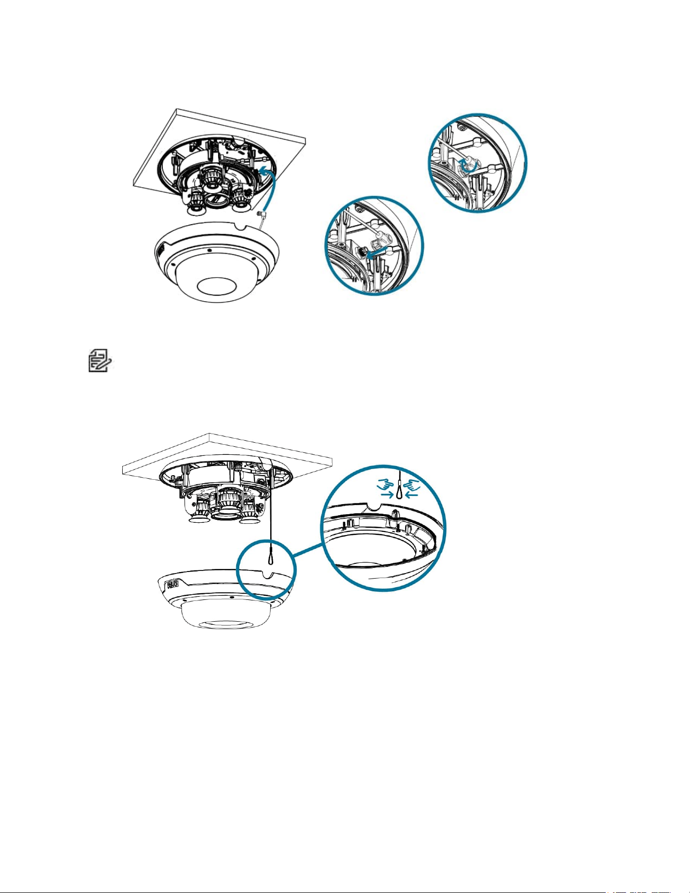
Resetting to Factory Default Settings
If the device no longer functions as expected, you can choose to reset the device to its factory default
settings.
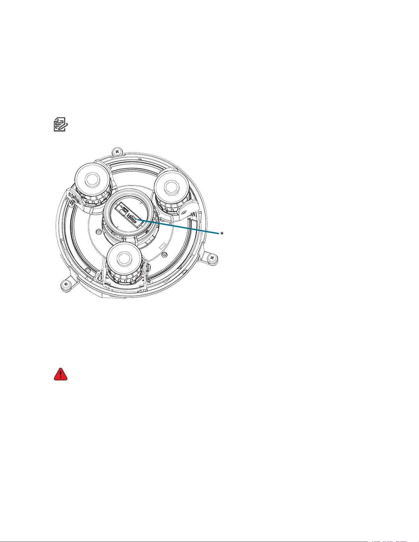
Use the firmware revert button to reset the device. The firmware revert button is shown in the following
diagram:
Note: Be careful not to scratch the dome bubble.
1. Ensure the camera is powered on.
2. Remove the dome cover.
3. Using a straightened paperclip or similar tool, gently press and hold the firmware revert button (*) for
two seconds.
4. Re-install the dome cover.
Do not apply excessive force. Inserting the tool too far may damage the camera.
Setting the IP Address Using the ARP/Ping Method
Complete the following steps to configure the camera to use a specific IP address:
The ARP/Ping Method will not work if the Disable setting static IP address through ARP/Ping method
checkbox is selected in the camera's web browser interface. For more information, see the Pelco Sarix
Multi Pro Camera.

Sarix® Multi Pro Camera Installation Manual
C6715M | 01/24/22
60
1. Locate and make note of the MAC Address (MAC) listed on the Serial Number Tag for reference.
2. Open a Command Prompt window and enter the following commands:
a. arp -s <New Camera IP Address> <Camera MAC Address>
For example: arp -s 192.168.1.10 00-18-85-12-45-78
b. ping -l 123 -t <New Camera IP Address>
For example: ping -l 123 -t 192.168.1.10
3. Reboot the camera.
4. Close the Command Prompt window when you see the following message:
Reply from <New Camera IP Address>: ...
Cleaning
Dome Bubble
If the video image becomes blurry or smudged in areas, it may be because the dome bubble requires
cleaning.
To clean the dome bubble:
l Use hand soap or a non-abrasive detergent to wash off dirt or fingerprints.
l Use a microfiber cloth or non-abrasive fabric to dry the dome bubble.
Important: Failure to use the recommended cleaning materials may result in a damaged or scratched dome
bubble. A damaged dome bubble may negatively impact image quality and cause unwanted IR light
reflecting into the lens.
Body
l Use a dry or lightly dampened cloth to clean the camera body.
l Do not use strong or abrasive detergents.


Sarix® Multi Pro Camera Installation Manual
Pelco, Inc.
625 W. Alluvial Ave., Fresno, California 93711 United States
(800) 289-9100 Tel
(800) 289-9150 Fax
+1 (559) 292-1981 International Tel
+1 (559) 348-1120 International Fax
www.pelco.com
Pelco, the Pelco logo, and other trademarks associated with Pelco products referred to in this publication are trademarks of Pelco, Inc.
or its affiliates. ONVIF and the ONVIF logo are trademarks of ONVIF Inc. All other product names and services are the property of their
respective companies. Product specifications and availability are subject to change without notice.
© Copyright 2022, Pelco, Inc. All rights reserved.