
Industrial Hi-PoE Switch
Quick Start Guide
UD36781B

i
Preface
Applicable Models
This manual is applicable to the models listed in the following table.
Model Description
DS-3T0306HP
Industrial 10/100 Mbps Hi-PoE switch
DS-3T0310HP
DS-3T0506HP
Industrial gigabit Hi-PoE switch
DS-3T0510HP
Symbol Conventions
The symbols that may be found in this document are defined as
follows.
Symbol Description
Provides additional information to emphasize
or supplement important points of the main
text.
Indicates a potentially hazardous situation,
which if not avoided, could result in equipment
damage, data loss, performance degradation,
or unexpected results.
Indicates a hazard with a high level of risk,
which if not avoided, will result in death or
serious injury.
1
1 Introduction
1.1 Product Introduction
0300HP and 0500HP series switches are industrial 10/100 Mbps
and gigabit Hi-PoE switches respectively, providing PoE power
supply technology and wider temperature range design on the
basis of network access to ensure stable data upload. In addition,
0300HP series switches support long-range transmission, port
isolation, and PoE watchdog functions.
1.2 Packing List
Please check if the package is damaged first. If the package is intact,
unpack it and check whether the accessories provided with the
product are available by referring to the packing list. Then, you can
continue to install the device.
Table 1-1 Packing List
Accessory Quantity
Switch × 1
DIN Rail Mount Clip × 2
Quick Start Guide × 1
Regulatory Compliance and Safety Information
× 1
1.3 Appearance
Device appearances vary with different models. The actual device
prevails.
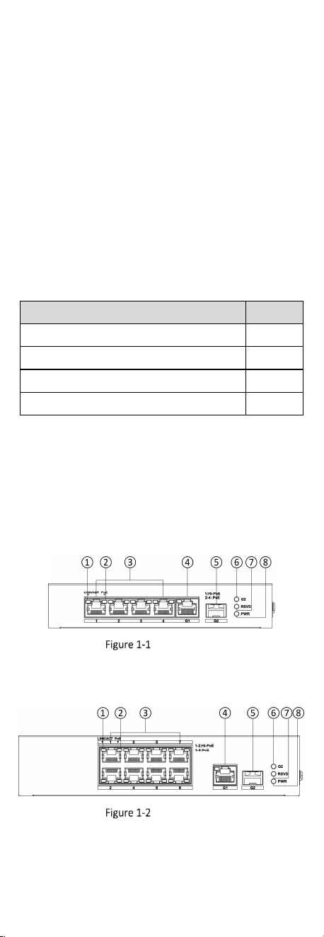
Front Panel
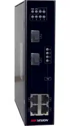
0306HP series switches feature one 10/100 Mbps Hi-PoE RJ45 port,
three 10/100 Mbps PoE RJ45 ports, one gigabit RJ45 port, and one
gigabit SFP fiber optical port.
0306HP Series
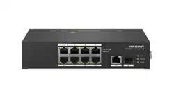
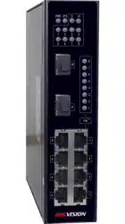
0310HP series switches feature two 10/100 Mbps Hi-PoE RJ45 ports,
six 10/100 Mbps PoE RJ45 ports, one gigabit RJ45 port, and one
gigabit SFP fiber optical port.
0310HP Series
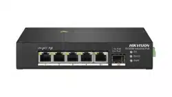
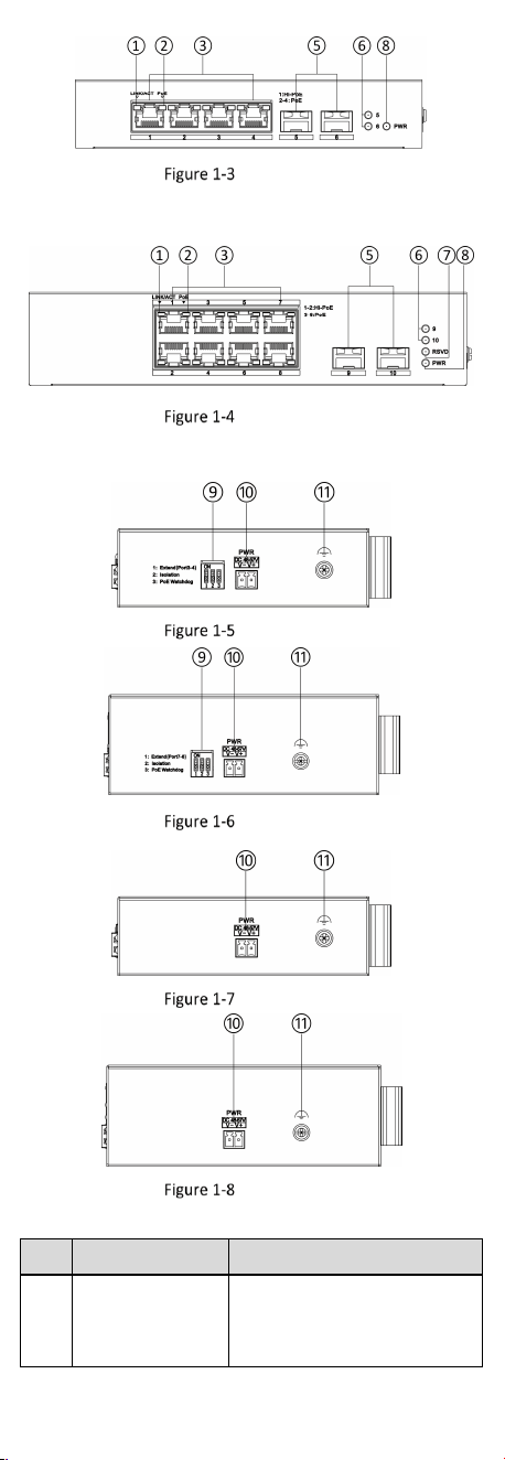
0506HP series switches feature one gigabit Hi-PoE RJ45 port, three
gigabit PoE RJ45 ports, and two gigabit SFP fiber optical ports.
2
0506HP Series
0510HP series switches feature two gigabit Hi-PoE RJ45 ports, six
gigabit PoE RJ45 ports, and two gigabit SFP fiber optical ports.
0510HP Series
Side Panel
0306HP Series
0310HP Series
0506HP Series
0510HP Series
Table 1-2 Port/Indicator Description
No.
Port/Indicator Description
①
LINK/ACT
Indicator
● Solid on: The port is
connected.
● Flashing: The port is
transmitting data.

3
No.
Port/Indicator Description
● Unlit: The port is
disconnected or connection
is abnormal.
②
PoE Indicator
● Solid on: The switch supplies
power to a powered device
(PD) normally.
● Unlit: The switch is
disconnected from a PD or
power supply is abnormal.
③
10/100 Mbps PoE
RJ45 Port
*0306HP&0310HP Series
Used for connection to a PD via
a network cable.
Gigabit PoE RJ45
Port
*0506HP&0510HP Series
④
Gigabit RJ45 Port
Used for connection to another
device via a network cable.
⑤
Gigabit SFP Fiber
Optical Port
Used for connection to another
device via an optical fiber when
plugged into with an optical
module.
⑥
G2 Port Indicator
*0306HP&0310HP Series
● Solid on: The gigabit SFP fiber
optical port is connected.
● Flashing: The gigabit SFP fiber
optical port is transmitting
data.
● Unlit: No gigabit SFP fiber
optical port connected or
connection is abnormal.
G5/G6 Port
Indicator
*0506HP Series
G9/G10 Port
Indicator
*0510HP Series
⑦
RSVD Indicator
Unlit: The indicator is reserved.
⑧
PWR Indicator
● Solid on: The switch is
powered on normally.
● Unlit: No power supply is
connected or power supply is
abnormal.
⑨
DIP Switch
Three modes are supported:
● Extend: Port 3 and 4 of
0306HP series switches and
ports 7 and 8 of 0310HP
series switches support
network transmission of up to
300 meters.
● Isolation: Data transmission
of each port is isolated from
each other to improve
network security.
● PoE Watchdog: Auto-detect
and restart cameras that do
not respond.
4
No.
Port/Indicator Description
⑩
Power Supply
Use a self-prepared AC power
cord or power adapter to
connect the switch to a socket.
⑪
Grounding
Terminal
Used for connection to the
grounding cable to protect the
switch from lightning.
Note
Port 1 of 0306HP and 0506HP series switches as well as ports 1 and
2 of 0310HP and 0510HP series switches are Hi-PoE RJ45 ports,
which can be connected to high-power devices.
2 Installation
Please select an appropriate installation method according to the
actual needs.
Note
The following figures are for illustration only. The actual device
prevails.
Before You Start
Ensure that the desktop or rail is stable and firm enough.
Keep the room well-ventilated. Leave at least 10 cm of heat
dissipation space around the device.
2.1 Desktop Placement
Place the device on the desk.
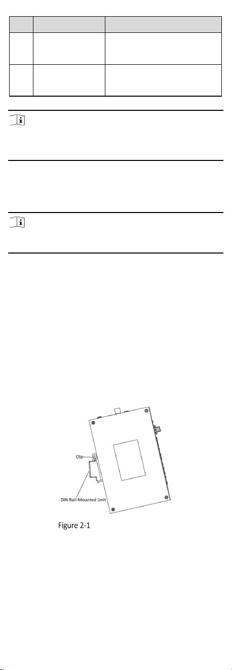
2.2 Rail-Mounted Installation
Steps
1. Fix the clip to the device.
2. Insert the end of the DIN rail-mounted unit into the notch under
the clip.
Rail-Mounted Installation
3. Press the DIN rail-mounted unit in quickly.
4. Optional: Use screws to fix the DIN rail-mounted unit onto the
device.
5
3 Wiring
3.1 Connect Grounding Cable
Grounding is used to quickly release overvoltage and overcurrent
induced by lightening on the device, and to protect personal safety.
Select an appropriate grounding method according to the
installation conditions.
Note
The following figures are for your reference only. The actual device
prevails.
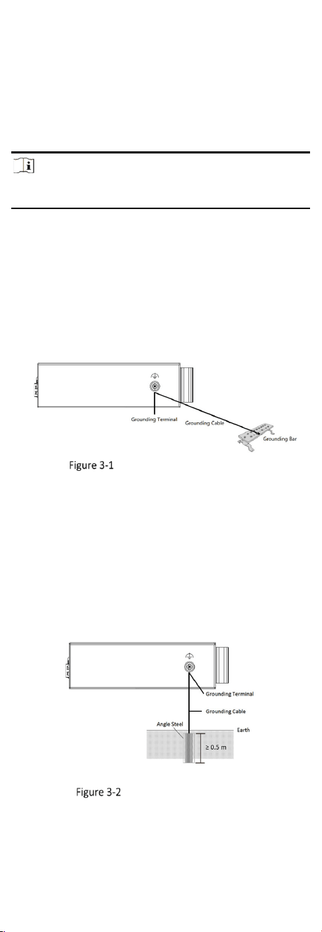
3.1.1 With Grounding Bar
If a grounding bar is available at the installation site, follow the
steps below.
Steps
1. Connect one end of the grounding cable to the binding post on
the grounding bar.
2. Connect the other end of the grounding cable to the grounding
terminal of the device and tighten the screw.
Grounding with Grounding Bar
3.1.2 Without Grounding Bar
If there is no grounding bar but the earth is nearby and the
grounding body is allowed to be buried, follow the steps below.
Steps
1. Bury an angle steel or steel pipe (≥ 0.5 m) into the earth.
2. Weld one end of the grounding cable to the angle steel or steel
pipe and embalm the welding point via electroplating or coating.
3. Connect the other end of the grounding cable to the grounding
terminal.
Grounding with Angle Steel
6
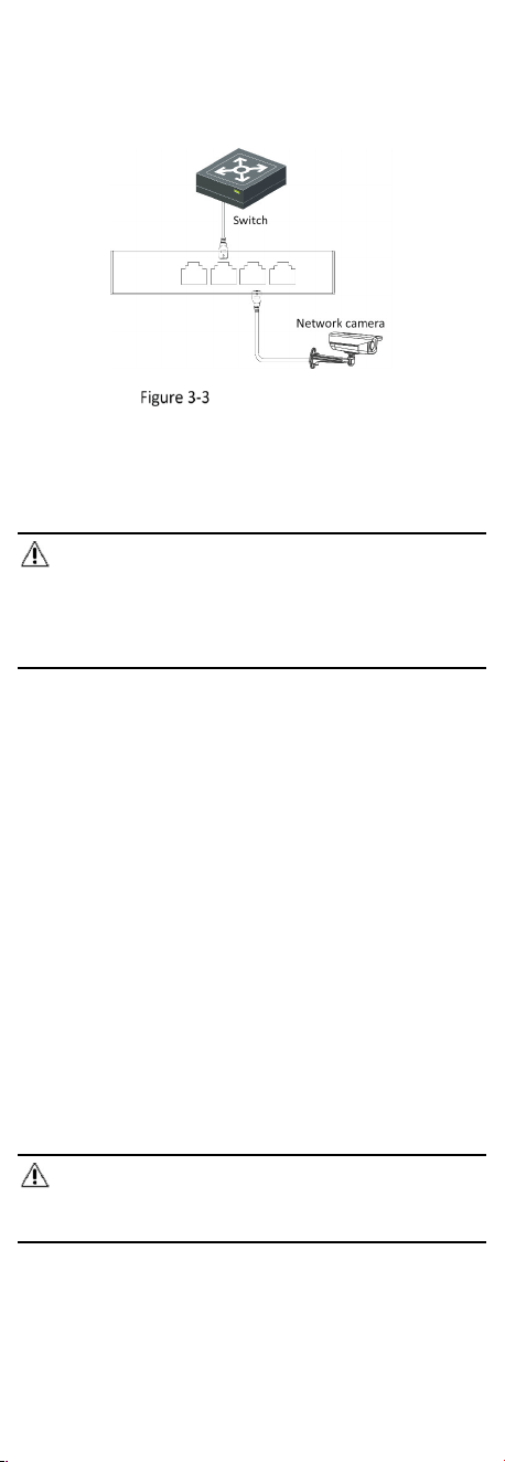
3.2 Connect RJ45 Port
Use a network cable to connect the device to the RJ45 port of a
peer device such as network camera (IPC), network video recorder
(NVR), switch, etc.
RJ45 Port Connection
3.3 Connect SFP Optical Module
Connecting an SFP optical module is supported when the device
has a fiber optical port.
Steps
Caution
●
Single-mode optical modules need to be paired for use.
●
Do not bend an optical fiber (curvature radius ≥ 10 cm) overly.
●
Do not look directly at an optical fiber connector because the
laser generated is harmful to eyes.
1. Connect the two paired SFP optical modules with an optical fiber.
2. Hold the SFP optical module from one side, and smoothly plug it
into the device along the SFP port slot until the optical module
and the device are closely attached.
3. After powering on the device, check the status of the optical port
indicator.
- If the indicator is lit, the link is connected.
- If the indicator is unlit, the link is disconnected. Check the line,
and make sure that the peer device has been enabled.
4 Device Powering-On
Please use a self-prepared AC power cord or power adapter to
power on the device.
Before powering on your device, make sure that:
• The operating power supply is compliant with rated input
standard.
• Port cables and grounding cables are correctly connected.
• If there is outdoor wiring, connect a lightning rod and a
lightening arrester to the cable.
Caution
Power cables and network cables cannot be wired together,
otherwise the PD or switch ports will be burnt.