
Video Intercom Villa Door Station
User Manual

Video Intercom Villa Door Station User Manual
i
Legal Information
© 2020 Hangzhou Hikvision Digital Technology Co., Ltd. All rights reserved.
About this Manual
The Manual includes instructions for using and managing the Product. Pictures, charts, images and
all other information hereinafter are for description and explanation only. The information
contained in the Manual is subject to change, without notice, due to firmware updates or other
reasons. Please find the latest version of this Manual at the Hikvision website
(https://www.hikvision.com/).
Please use this Manual with the guidance and assistance of professionals trained in supporting the
Product.
Trademarks
and other Hikvision's trademarks and logos are the properties of
Hikvision in various jurisdictions.
Other trademarks and logos mentioned are the properties of their respective owners.
Disclaimer
TO THE MAXIMUM EXTENT PERMITTED BY APPLICABLE LAW, THIS MANUAL AND THE PRODUCT
DESCRIBED, WITH ITS HARDWARE, SOFTWARE AND FIRMWARE, ARE PROVIDED “AS IS” AND
“WITH ALL FAULTS AND ERRORS”. HIKVISION MAKES NO WARRANTIES, EXPRESS OR IMPLIED,
INCLUDING WITHOUT LIMITATION, MERCHANTABILITY, SATISFACTORY QUALITY, OR FITNESS FOR
A PARTICULAR PURPOSE. THE USE OF THE PRODUCT BY YOU IS AT YOUR OWN RISK. IN NO EVENT
WILL HIKVISION BE LIABLE TO YOU FOR ANY SPECIAL, CONSEQUENTIAL, INCIDENTAL, OR INDIRECT
DAMAGES, INCLUDING, AMONG OTHERS, DAMAGES FOR LOSS OF BUSINESS PROFITS, BUSINESS
INTERRUPTION, OR LOSS OF DATA, CORRUPTION OF SYSTEMS, OR LOSS OF DOCUMENTATION,
WHETHER BASED ON BREACH OF CONTRACT, TORT (INCLUDING NEGLIGENCE), PRODUCT
LIABILITY, OR OTHERWISE, IN CONNECTION WITH THE USE OF THE PRODUCT, EVEN IF HIKVISION
HAS BEEN ADVISED OF THE POSSIBILITY OF SUCH DAMAGES OR LOSS.
YOU ACKNOWLEDGE THAT THE NATURE OF INTERNET PROVIDES FOR INHERENT SECURITY RISKS,
AND HIKVISION SHALL NOT TAKE ANY RESPONSIBILITIES FOR ABNORMAL OPERATION, PRIVACY
LEAKAGE OR OTHER DAMAGES RESULTING FROM CYBER-ATTACK, HACKER ATTACK, VIRUS
INSPECTION, OR OTHER INTERNET SECURITY RISKS; HOWEVER, HIKVISION WILL PROVIDE TIMELY
TECHNICAL SUPPORT IF REQUIRED.
YOU AGREE TO USE THIS PRODUCT IN COMPLIANCE WITH ALL APPLICABLE LAWS, AND YOU ARE
SOLELY RESPONSIBLE FOR ENSURING THAT YOUR USE CONFORMS TO THE APPLICABLE LAW.
ESPECIALLY, YOU ARE RESPONSIBLE, FOR USING THIS PRODUCT IN A MANNER THAT DOES NOT
INFRINGE ON THE RIGHTS OF THIRD PARTIES, INCLUDING WITHOUT LIMITATION, RIGHTS OF
PUBLICITY, INTELLECTUAL PROPERTY RIGHTS, OR DATA PROTECTION AND OTHER PRIVACY RIGHTS.
YOU SHALL NOT USE THIS PRODUCT FOR ANY PROHIBITED END-USES, INCLUDING THE
DEVELOPMENT OR PRODUCTION OF WEAPONS OF MASS DESTRUCTION, THE DEVELOPMENT OR

Video Intercom Villa Door Station User Manual
ii
PRODUCTION OF CHEMICAL OR BIOLOGICAL WEAPONS, ANY ACTIVITIES IN THE CONTEXT RELATED
TO ANY NUCLEAR EXPLOSIVE OR UNSAFE NUCLEAR FUEL-CYCLE, OR IN SUPPORT OF HUMAN
RIGHTS ABUSES.
IN THE EVENT OF ANY CONFLICTS BETWEEN THIS MANUAL AND THE APPLICABLE LAW, THE LATER
PREVAILS.
Video Intercom Villa Door Station User Manual
iii
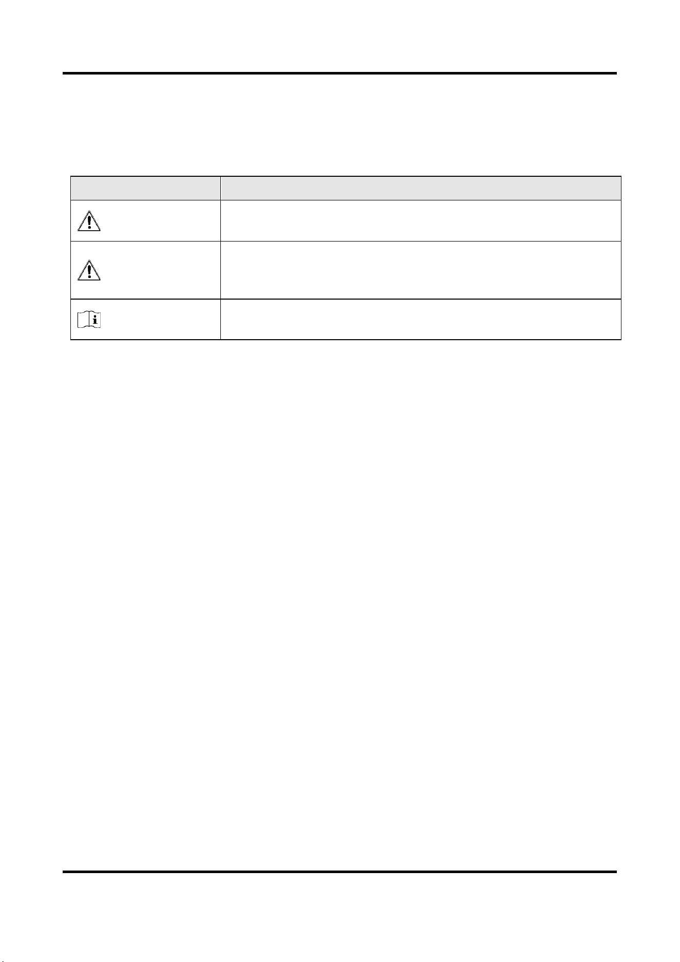
Symbol Conventions
The symbols that may be found in this document are defined as follows.
Symbol
Description
Danger
Indicates a hazardous situation which, if not avoided, will or could
result in death or serious injury.
Caution
Indicates a potentially hazardous situation which, if not avoided,
could result in equipment damage, data loss, performance
degradation, or unexpected results.
Note
Provides additional information to emphasize or supplement
important points of the main text.

Video Intercom Villa Door Station User Manual
iv
Safety Instruction
●
Warning
●
All the electronic operation should be strictly compliance with the electrical safety regulations,
fire prevention regulations and other related regulations in your local region.
●
Please use the power adapter, which is provided by normal company. The power consumption
cannot be less than the required value.
●
Do not connect several devices to one power adapter as adapter overload may cause over-heat
or fire hazard.
●
Please make sure that the power has been disconnected before you wire, install or dismantle
the device.
●
When the product is installed on wall or ceiling, the device shall be firmly fixed.
●
If smoke, odors or noise rise from the device, turn off the power at once and unplug the power
cable, and then please contact the service center.
●
If the product does not work properly, please contact your dealer or the nearest service
center. Never attempt to disassemble the device yourself. (We shall not assume any
responsibility for problems caused by unauthorized repair or maintenance.)
●
Caution
●
Do not drop the device or subject it to physical shock, and do not expose it to high
electromagnetism radiation. Avoid the equipment installation on vibrations surface or places
subject to shock (ignorance can cause equipment damage).
●
Do not place the device in extremely hot (refer to the specification of the device for the detailed
operating temperature), cold, dusty or damp locations, and do not expose it to high
electromagnetic radiation.
●
The device cover for indoor use shall be kept from rain and moisture.
●
Exposing the equipment to direct sun light, low ventilation or heat source such as heater or
radiator is forbidden (ignorance can cause fire danger).
●
Do not aim the device at the sun or extra bright places. A blooming or smear may occur
otherwise (which is not a malfunction however), and affecting the endurance of sensor at the
same time.
●
Please use the provided glove when open up the device cover, avoid direct contact with the
device cover, because the acidic sweat of the fingers may erode the surface coating of the
device cover.
●
Please use a soft and dry cloth when clean inside and outside surfaces of the device cover, do
not use alkaline detergents.
●
Please keep all wrappers after unpack them for future use. In case of any failure occurred, you
need to return the device to the factory with the original wrapper. Transportation without the
original wrapper may result in damage on the device and lead to additional costs.
●
Improper use or replacement of the battery may result in hazard of explosion. Replace with the
same or equivalent type only. Dispose of used batteries according to the instructions provided
Video Intercom Villa Door Station User Manual
v
by the battery manufacturer.
●
Input voltage should meet both the SELV and the Limited Power Source according to 60950-1
standard.
●
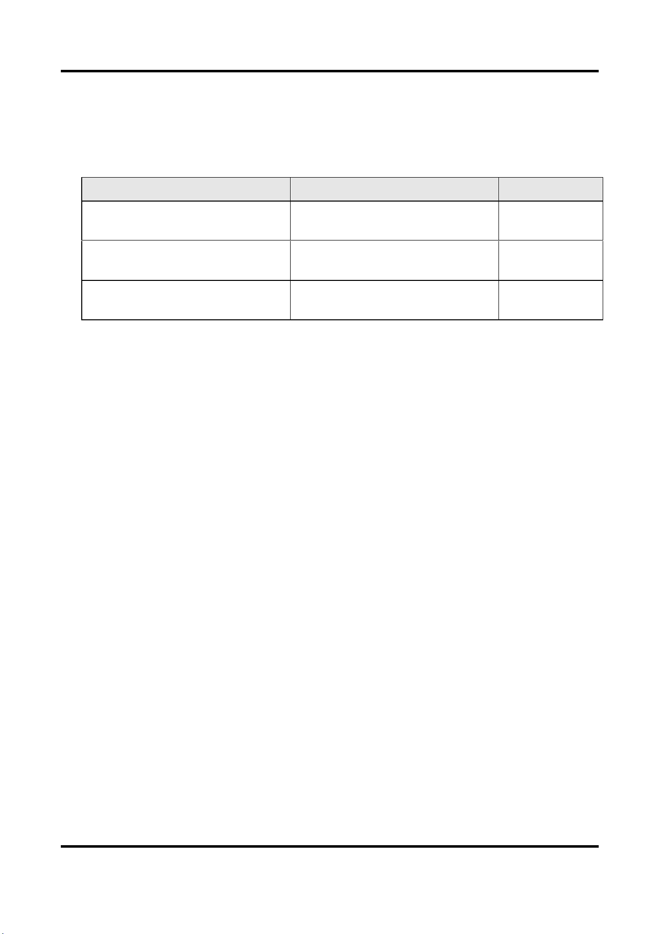
The power supply must conform to LPS. The recommended adaptor models and manufacturers
are shown as below. Use the attached adapter, and do not change the adaptor randomly.
Model
Manufacturer
Standard
ADS-24S-12 1224GPCN
SHENZHEN HONOR ELECTRONIC
CO.,LTD
CEE
G0549-240-050
SHENZHEN GOSPELL DIGITAL
TECHNOLOGY CO.,LTD
CEE
TS-A018-120015Ec
SHENZHEN TRANSIN
TECHNOLOGIES CO., LTD
CEE

Video Intercom Villa Door Station User Manual
vi
Regulatory Information
FCC Information
Please take attention that changes or modification not expressly approved by the party
responsible for compliance could void the user's authority to operate the equipment.
FCC compliance: This equipment has been tested and found to comply with the limits for a Class B
digital device, pursuant to part 15 of the FCC Rules. These limits are designed to provide
reasonable protection against harmful interference in a residential installation. This equipment
generates, uses and can radiate radio frequency energy and, if not installed and used in
accordance with the instructions, may cause harmful interference to radio communications.
However, there is no guarantee that interference will not occur in a particular installation. If this
equipment does cause harmful interference to radio or television reception, which can be
determined by turning the equipment off and on, the user is encouraged to try to correct the
interference by one or more of the following measures:
—Reorient or relocate the receiving antenna.
—Increase the separation between the equipment and receiver.
—Connect the equipment into an outlet on a circuit different from that to which the receiver is
connected.
—Consult the dealer or an experienced radio/TV technician for help
FCC Conditions
This device complies with part 15 of the FCC Rules. Operation is subject to the following two
conditions:
1. This device may not cause harmful interference.
2. This device must accept any interference received, including interference that may cause
undesired operation.
EU Conformity Statement
This product and - if applicable - the supplied accessories too are marked with
"CE" and comply therefore with the applicable harmonized European standards
listed under the EMC Directive 2014/30/EU, the RoHS Directive 2011/65/EU
2012/19/EU (WEEE directive): Products marked with this symbol cannot be
disposed of as unsorted municipal waste in the European Union. For proper
recycling, return this product to your local supplier upon the purchase of
equivalent new equipment, or dispose of it at designated collection points. For
more information see: www.recyclethis.info
2006/66/EC (battery directive): This product contains a battery that cannot be
disposed of as unsorted municipal waste in the European Union. See the product
documentation for specific battery information. The battery is marked with this
symbol, which may include lettering to indicate cadmium (Cd), lead (Pb), or
mercury (Hg). For proper recycling, return the battery to your supplier or to a

Video Intercom Villa Door Station User Manual
vii
designated collection point. For more information see:www.recyclethis.info
Industry Canada ICES-003 Compliance
This device meets the CAN ICES-3 (B)/NMB-3(B) standards requirements.

Video Intercom Villa Door Station User Manual
viii
Contents
Chapter 1 Appearance ......................................................................................................................... 1
Chapter 2 Terminal and Wiring Description ....................................................................................... 6
2.1 Terminal Description ............................................................................................................. 6
2.2 Wiring Description ................................................................................................................. 7
2.2.1 Door Lock Wiring ........................................................................................................ 7
2.2.2 Door Contact Wiring ................................................................................................... 8
2.2.3 Exit Button Wiring ...................................................................................................... 9
2.2.4 Alarm Input Device Wiring ......................................................................................... 9
Chapter 3 Installation ........................................................................................................................ 10
3.1 Accessory Introduction........................................................................................................ 10
3.2 Surface Mounting with Protective Shield........................................................................... 11
3.3 Surface Mounting without Protective Shield ..................................................................... 12
3.4 Flush Mounting with Protective Shield .............................................................................. 14
3.5 Flush Mounting without Protective Shield......................................................................... 16
Chapter 4 Activation .......................................................................................................................... 19
4.1 Activate Device via Web...................................................................................................... 19
4.2 Activate Device via Client Software .................................................................................... 19
4.3 Edit Network Parameters .................................................................................................... 20
Chapter 5 Remote Configuration via Web........................................................................................ 21
5.1 Live View .............................................................................................................................. 21
5.2 User Management ............................................................................................................... 21
5.3 Device Management ........................................................................................................... 22
5.4 Parameters Settings ............................................................................................................ 23
5.4.1 Local Parameters Settings ........................................................................................ 23
5.4.2 System Settings ........................................................................................................ 25
5.4.3 Network Settings ...................................................................................................... 27
5.4.4 Video & Audio Settings ............................................................................................ 32
5.4.5 Image Settings .......................................................................................................... 35
5.4.6 Event Settings ........................................................................................................... 37

Video Intercom Villa Door Station User Manual
ix
5.4.7 Schedule Settings ..................................................................................................... 40
5.4.8 Intercom Settings ..................................................................................................... 41
5.4.9 Access Control Settings ............................................................................................ 44
Chapter 6 Configuration via Client Software.................................................................................... 47
6.1 Device Management ........................................................................................................... 47
6.1.1 Add Online Device .................................................................................................... 47
6.1.2 Add Device by IP Address......................................................................................... 48
6.1.3 Add Device by IP Segment ....................................................................................... 49
6.2 Live View via Door Station .................................................................................................. 49
6.3 Organization Management ................................................................................................. 49
6.3.1 Add Organization...................................................................................................... 49
6.3.2 Modify and Delete Organization ............................................................................. 49
6.4 Person Management ........................................................................................................... 50
6.4.1 Add Person................................................................................................................ 50
6.4.2 Modify and Delete Person ....................................................................................... 51
6.4.3 Change Person to Other Organization ..................................................................... 51
6.4.4 Import and Export Person Information ................................................................... 52
6.4.5 Get Person Information from Device ...................................................................... 52
6.4.6 Issue Card in Batch ................................................................................................... 53
6.4.7 Permission Settings .................................................................................................. 54
6.5 Video Intercom Settings ...................................................................................................... 55
6.5.1 Receive Call from Door Station ................................................................................ 55
6.5.2 Release Notice .......................................................................................................... 56
6.5.3 Search Video Intercom Information ........................................................................ 56
6.5.4 Upload Armed Information...................................................................................... 58
A. Communication Matrix and Device Command ............................................................................ 59
Video Intercom Villa Door Station User Manual
1
Chapter 1 Appearance
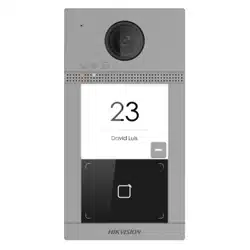
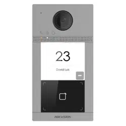
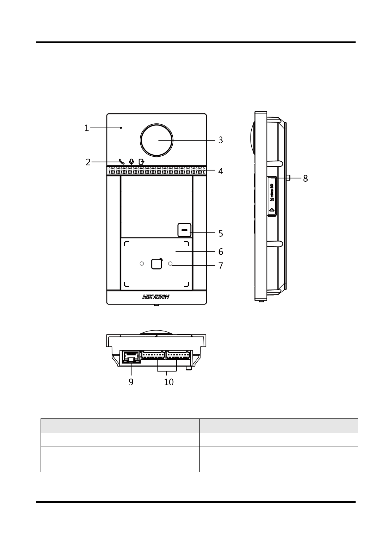
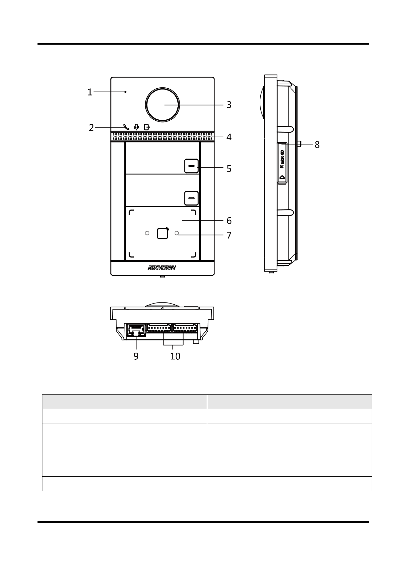
Single-Button Villa Door Station
Figure 1-1 Single-Button Villa Door Station Appearance
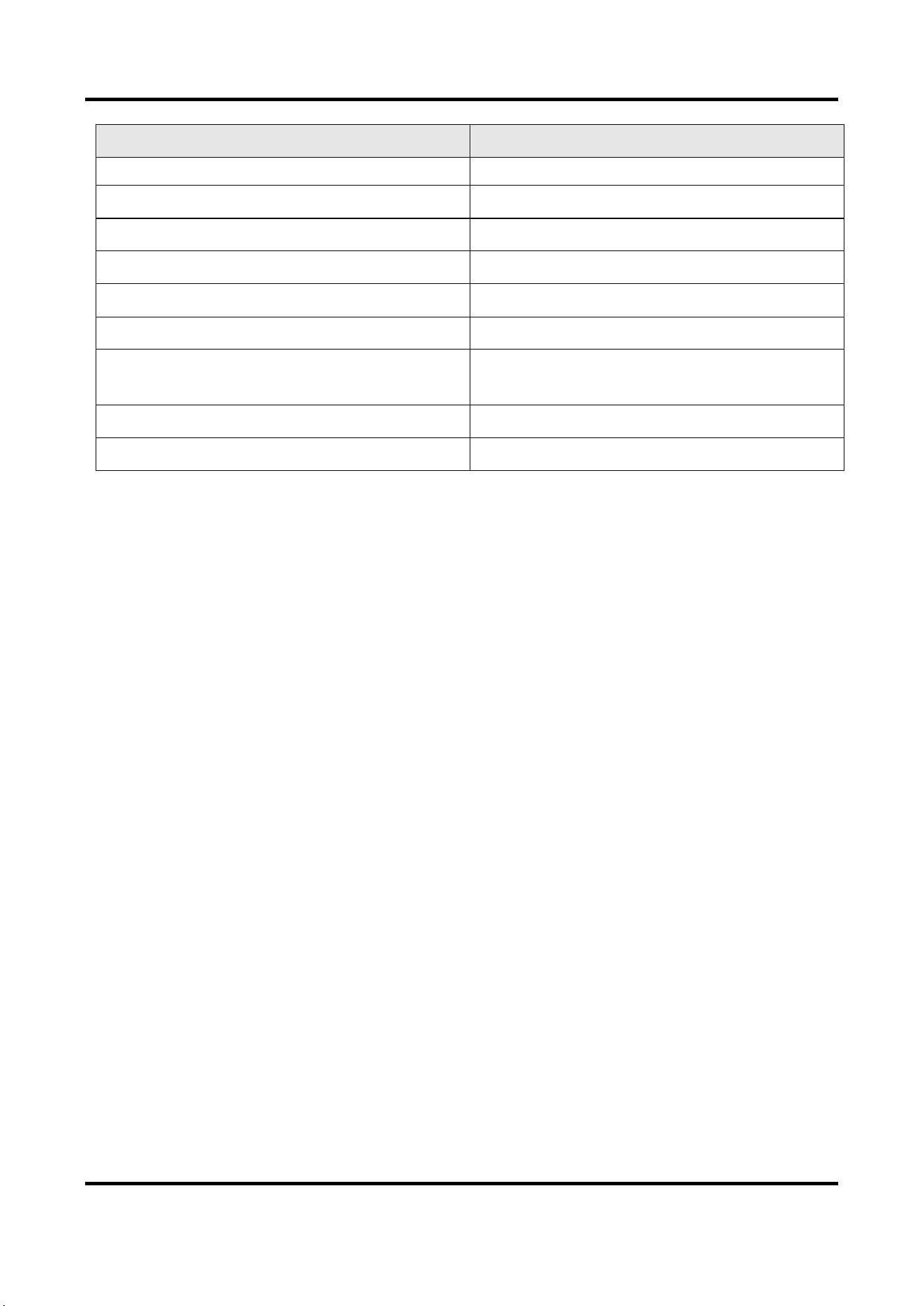
Table 1-1 Description
No.
Description
1
Microphone
2
Indicator
Unlock (Green)/ Call (Orange)/ Communicate
Video Intercom Villa Door Station User Manual
2
No.
Description
(White)
3
Camera
4
Loudspeaker
5
Button
6
Card Reading Area
7
IR Light
8
Micro SD Card Slot (Reserved) & Debugging
Port
9
LAN
10
Terminals
Video Intercom Villa Door Station User Manual
3
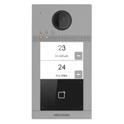
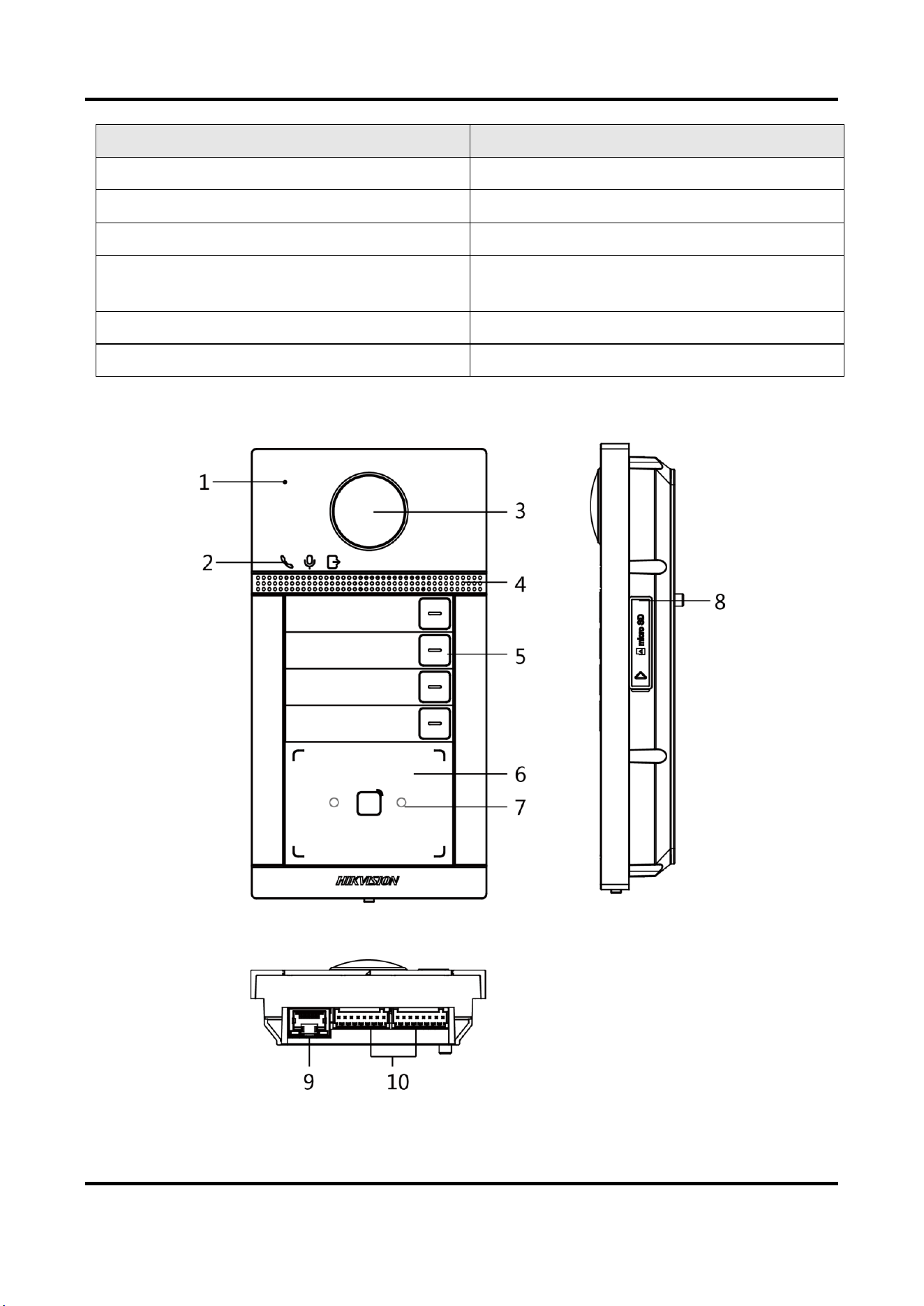
Two-Button Villa Door Station
Figure 1-2 Two-Button Villa Door Station Appearance
Table 1-2 Description
No.
Description
1
Microphone
2
Indicator
Unlock (Green)/ Call (Orange)/ Communicate
(White)
3
Camera
4
Loudspeaker
Video Intercom Villa Door Station User Manual
4
No.
Description
5
Button
6
Card Reading Area
7
IR Light
8
Micro SD Card Slot (Reserved) & Debugging
Port
9
LAN
10
Terminals
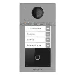
Four-Button Villa Door Station
Figure 1-3 Four-Button Villa Door Station Appearance
Video Intercom Villa Door Station User Manual
5
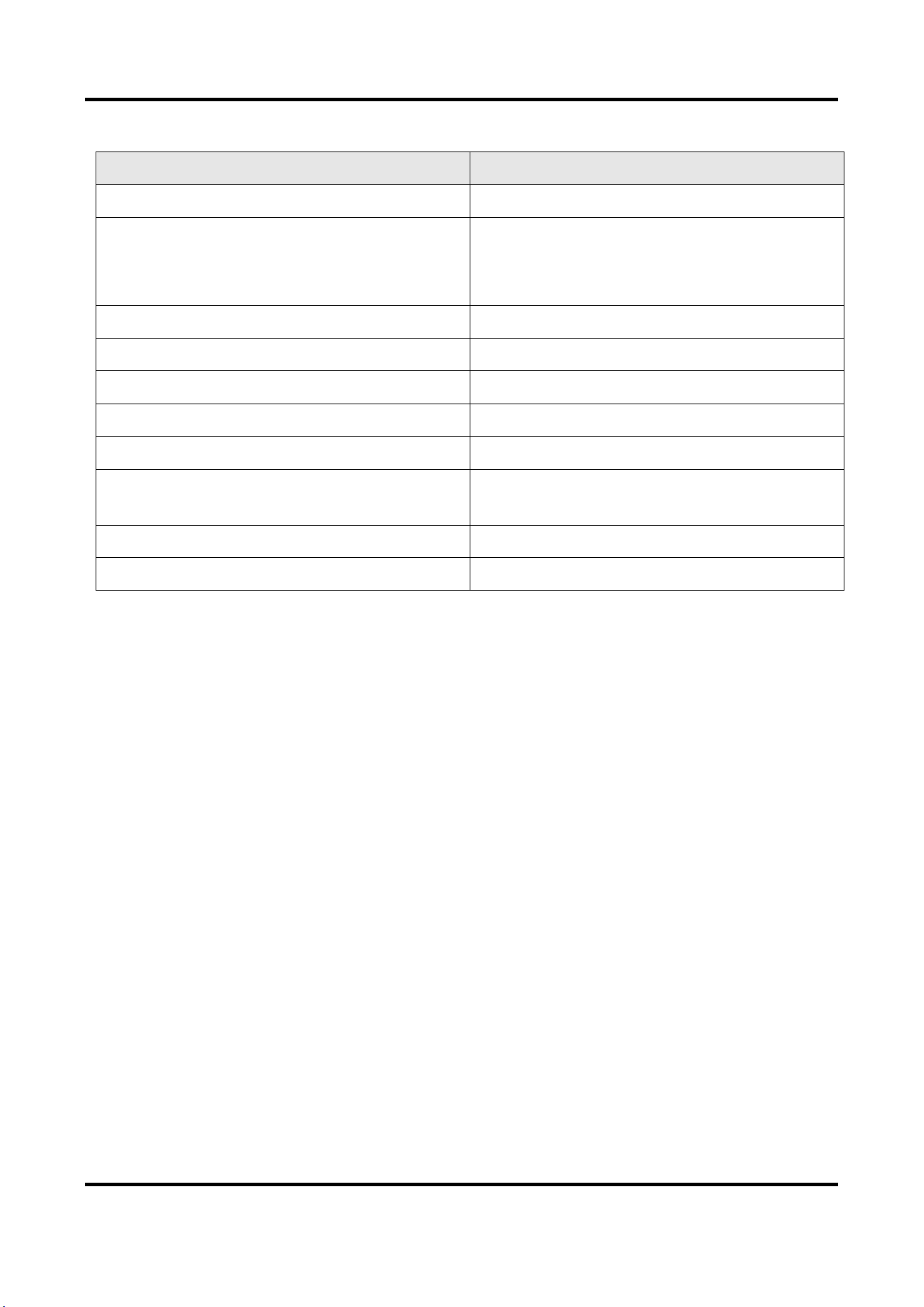
Table 1-3 Description
No.
Description
1
Microphone
2
Indicator
Unlock (Green)/ Call (Orange)/ Communicate
(White)
3
Camera
4
Loudspeaker
5
Button
6
Card Reading Area
7
IR Light
8
Micro SD Card Slot (Reserved) & Debugging
Port
9
LAN
10
Terminals
Video Intercom Villa Door Station User Manual
6
Chapter 2 Terminal and Wiring Description
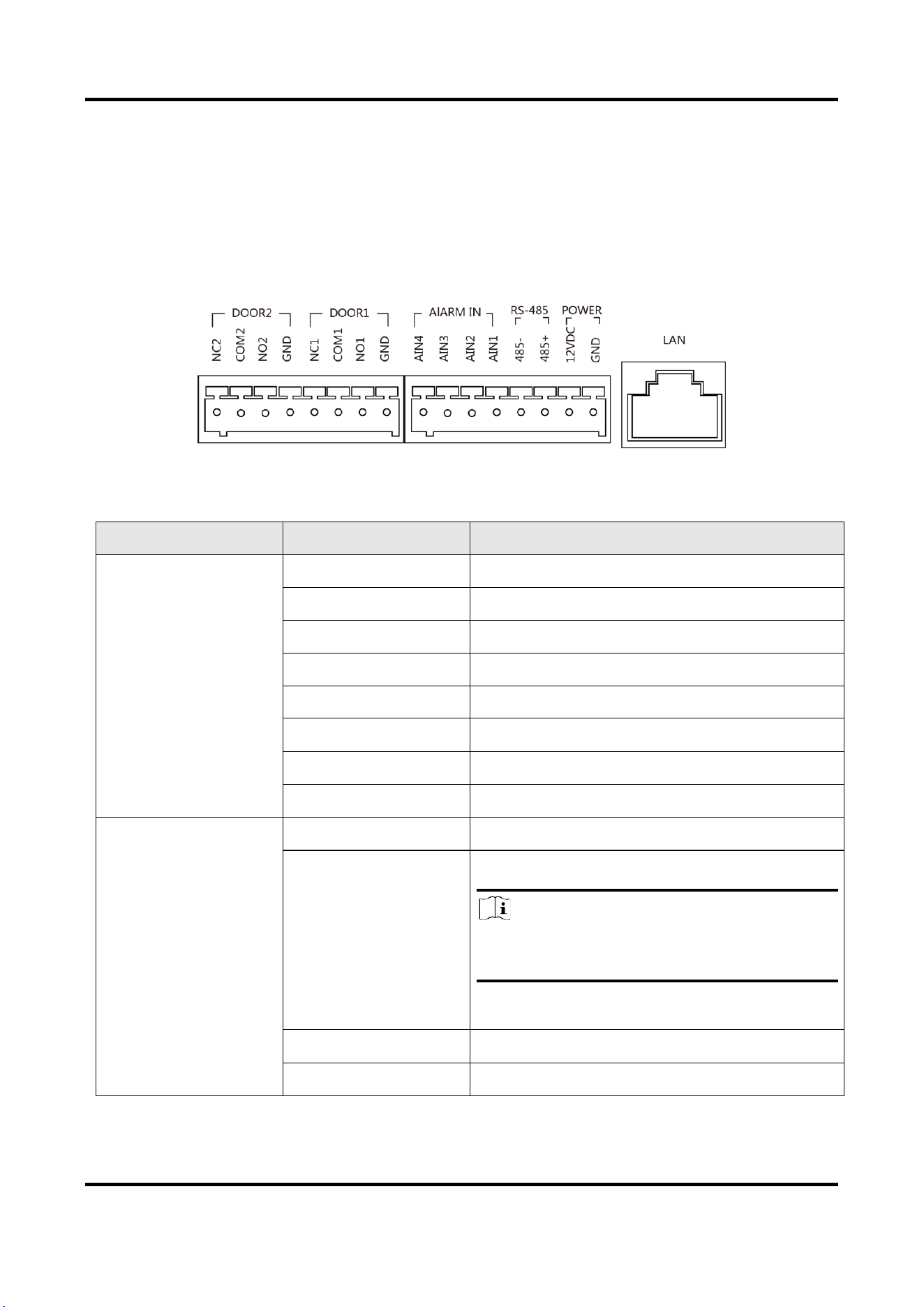
2.1 Terminal Description
Figure 2-1 Terminal Description
Table 2-1 Description of Terminal and Interfaces
Name
Interface
Description
DOOR
NC2
Door Lock Relay Output 2 (NC)
COM2
Common Interface
NO2
Door Lock Relay Output 2 (NO)
GND
Grounding
NC1
Door Lock Relay Output 1 (NO)
COM1
Common Interface
NO1
Door Lock Relay Output 1 (NO)
GND
Grounding
ALARM IN
AI1
Alarm Input 1 (For the access of Door Contact)
AI2
Alarm Input 2 (For the access of Door Contact)
Note
Before accessing to the Door Contact, select
Input as Door Status in I/O Settings page first.
AI3
Alarm Input 3 (For the access of Exit Button)
AI4
Alarm Input 4 (For the access of Exit Button)
Video Intercom Villa Door Station User Manual
7
Name
Interface
Description
Note
Before accessing to the Exit Button, select
Input as Exit Button in I/O Settings page first.
RS-485
485+
RS-485 Communication Interface
485-
Power Input
12 VDC
12 VDC Input
GND
Network
LAN
Network Interface
2.2 Wiring Description
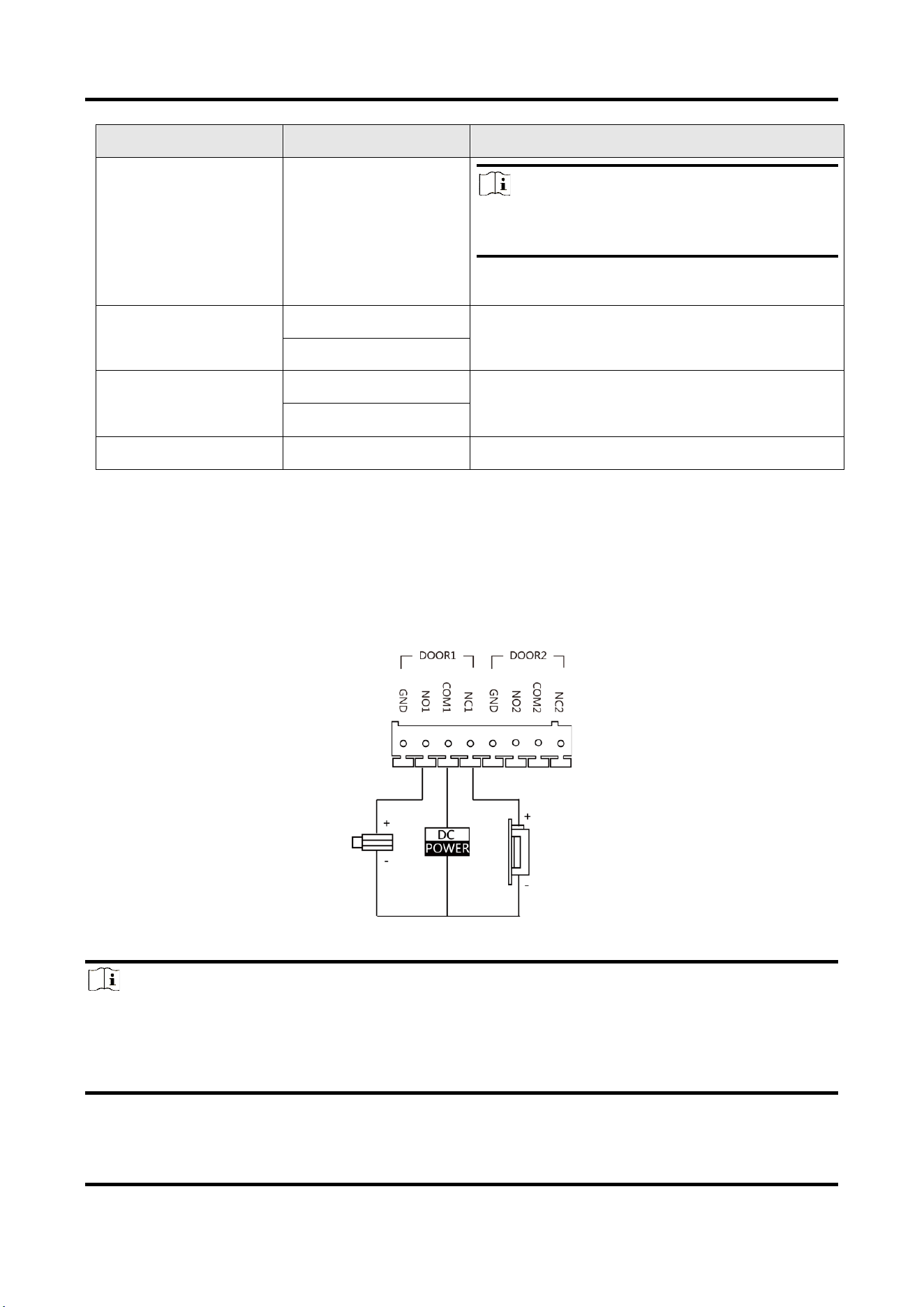
2.2.1 Door Lock Wiring
Figure 2-2 Door Lock Wiring
Note
●
Terminal NC1/COM1 is set as default for accessing magnetic lock/electric bolt; terminal
NO1/COM1 is set as default for accessing electric strike.
●
To connect electric lock in terminal NO2/COM2/NC2, it is required to set the output of terminal
NO2/COM2/NC2 to be electric lock with iVMS-4200 client software.
Video Intercom Villa Door Station User Manual
8
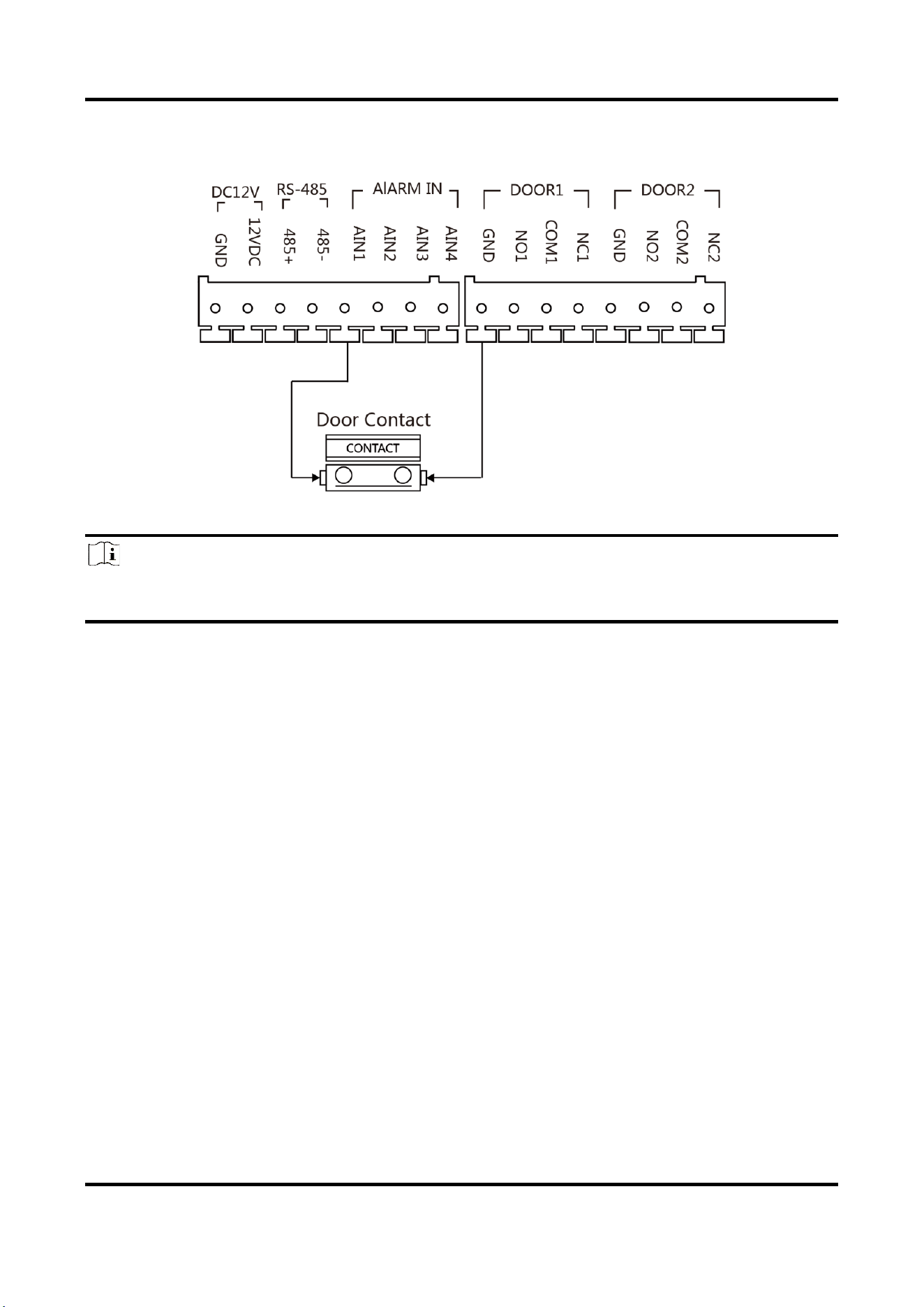
2.2.2 Door Contact Wiring
Figure 2-3 Door Contact Wiring
Note
If the door contact is not used, the corresponding input interface needs to be grounded.
Otherwise the door light will stay open.
Video Intercom Villa Door Station User Manual
9
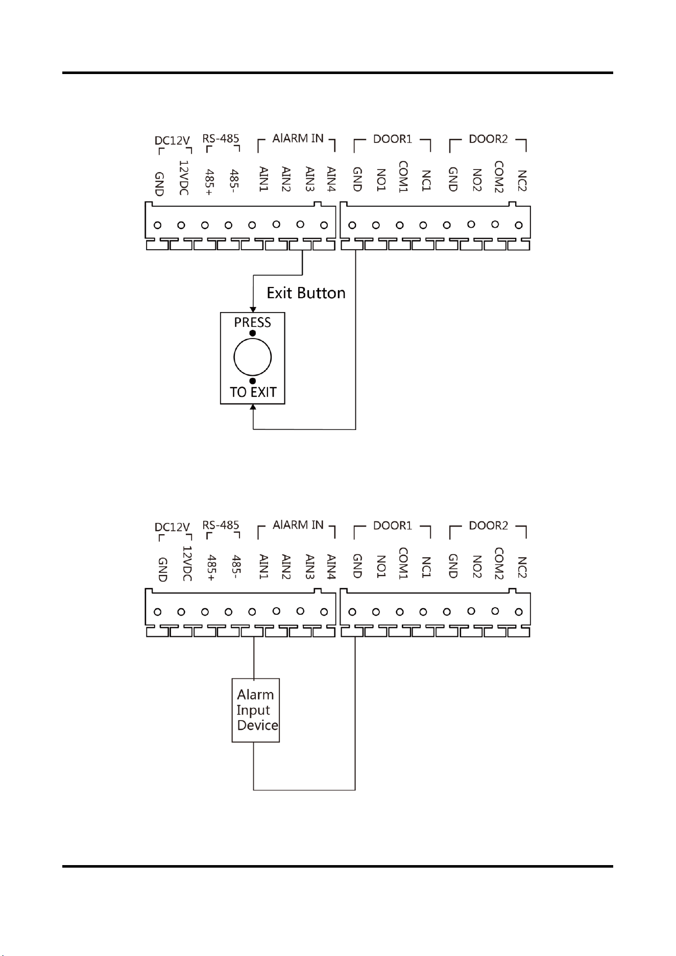
2.2.3 Exit Button Wiring
Figure 2-4 Exit Button Wiring
2.2.4 Alarm Input Device Wiring
Figure 2-5 Alarm Input Device Wiring
Video Intercom Villa Door Station User Manual
10
Chapter 3 Installation
Note
●
Make sure the device in the package is in good condition and all the assembly parts are
included.
●
Make sure your power supply matches your door station.
●
Make sure all the related equipment is power-off during the installation.
●
Check the product specification for the installation environment.
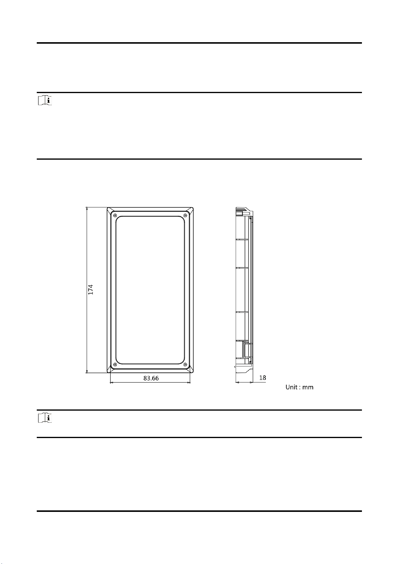
3.1 Accessory Introduction
Figure 3-1 Accessory Introduction
Note
The dimension of gang box for door station is: 174 (length) × 83.66 (width) × 18 (depth) mm.
Video Intercom Villa Door Station User Manual
11
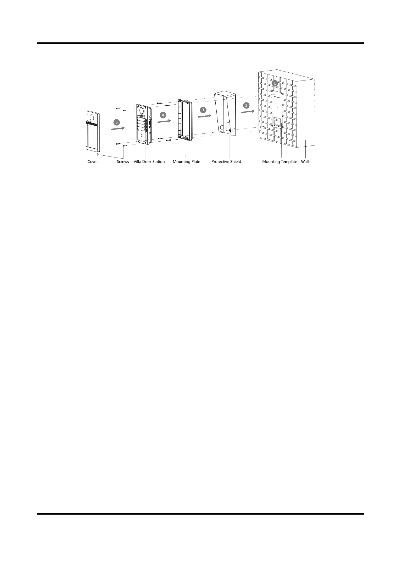
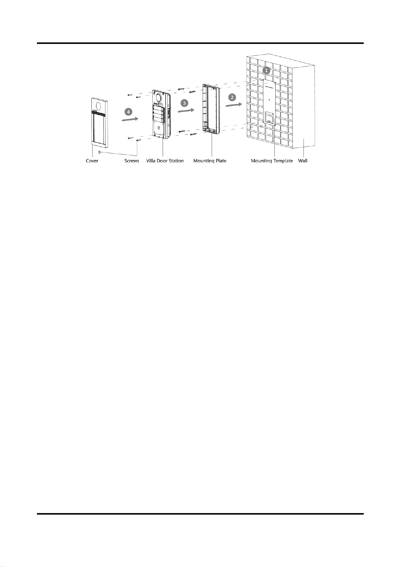
3.2 Surface Mounting with Protective Shield
Before You Start
●
Tools that you need to prepare for installation: Drill (ø2.846) and gradienter.
●
Purchase the protective shield before installation.
Steps
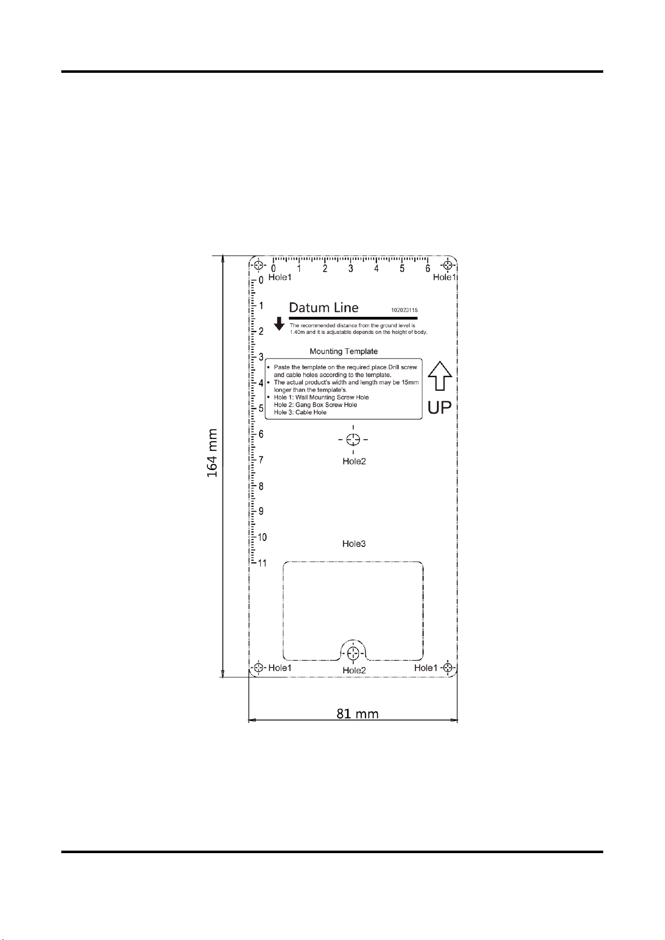
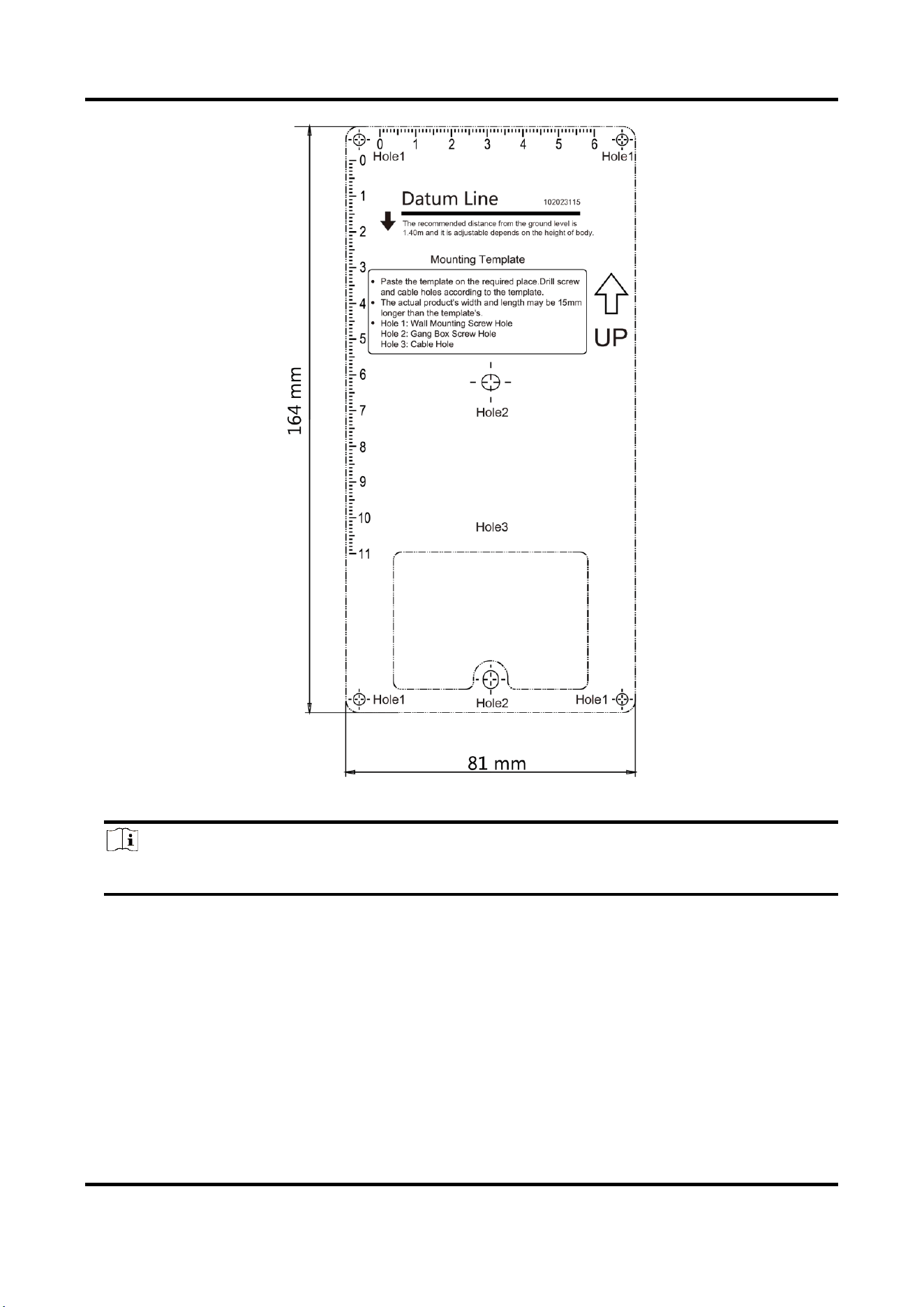
1. Stick the mounting template on the wall. Drill screw holes according to the mounting template.
Remove the template from the wall.
Figure 3-2 Mounting Template
2. Align the protective shield with mounting template.
3. Secure the mounting plate on the wall with 4 supplied screws according to the screw holes.
4. Secure the device on the mounting plate with 4 supplied set screws.
Video Intercom Villa Door Station User Manual
12
5. Fix the cover onto the device with the screw.
Figure 3-3 Surface Mounting with Protective Shield
3.3 Surface Mounting without Protective Shield
Before You Start
Tools that you need to prepare for installation: Drill (ø2.846) and gradienter.
Steps
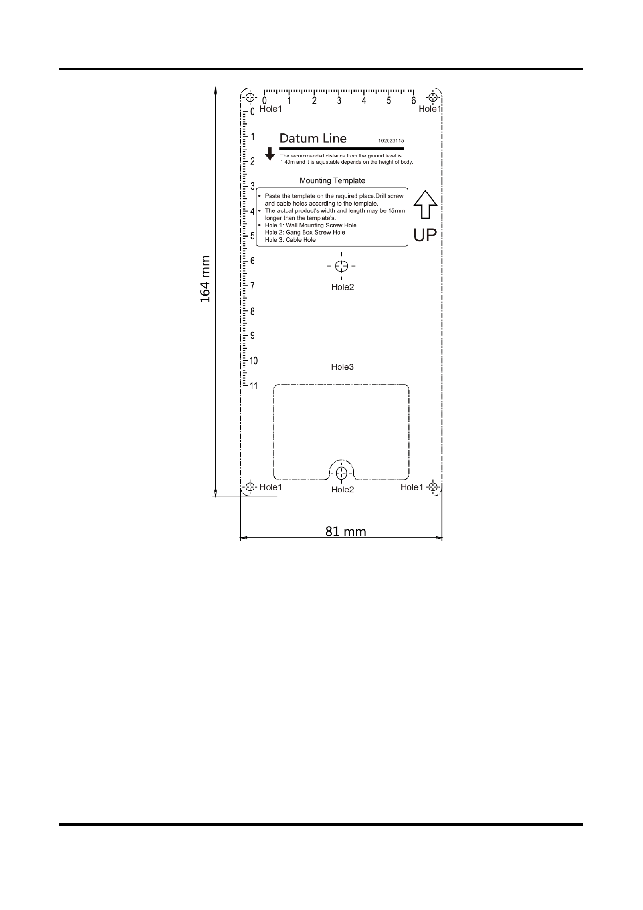
1. Stick the mounting template on the wall. Drill screw holes according to the mounting template.
Remove the template from the wall.
Video Intercom Villa Door Station User Manual
13
Figure 3-4 Mounting Template
2. Secure the mounting plate on the wall with 4 supplied screws according to the screw holes.
3. Secure the device on the mounting plate with 4 supplied set screws.
4. Fix the cover onto the device with the screw.
Video Intercom Villa Door Station User Manual
14
Figure 3-5 Surface Mounting without Protective Shield
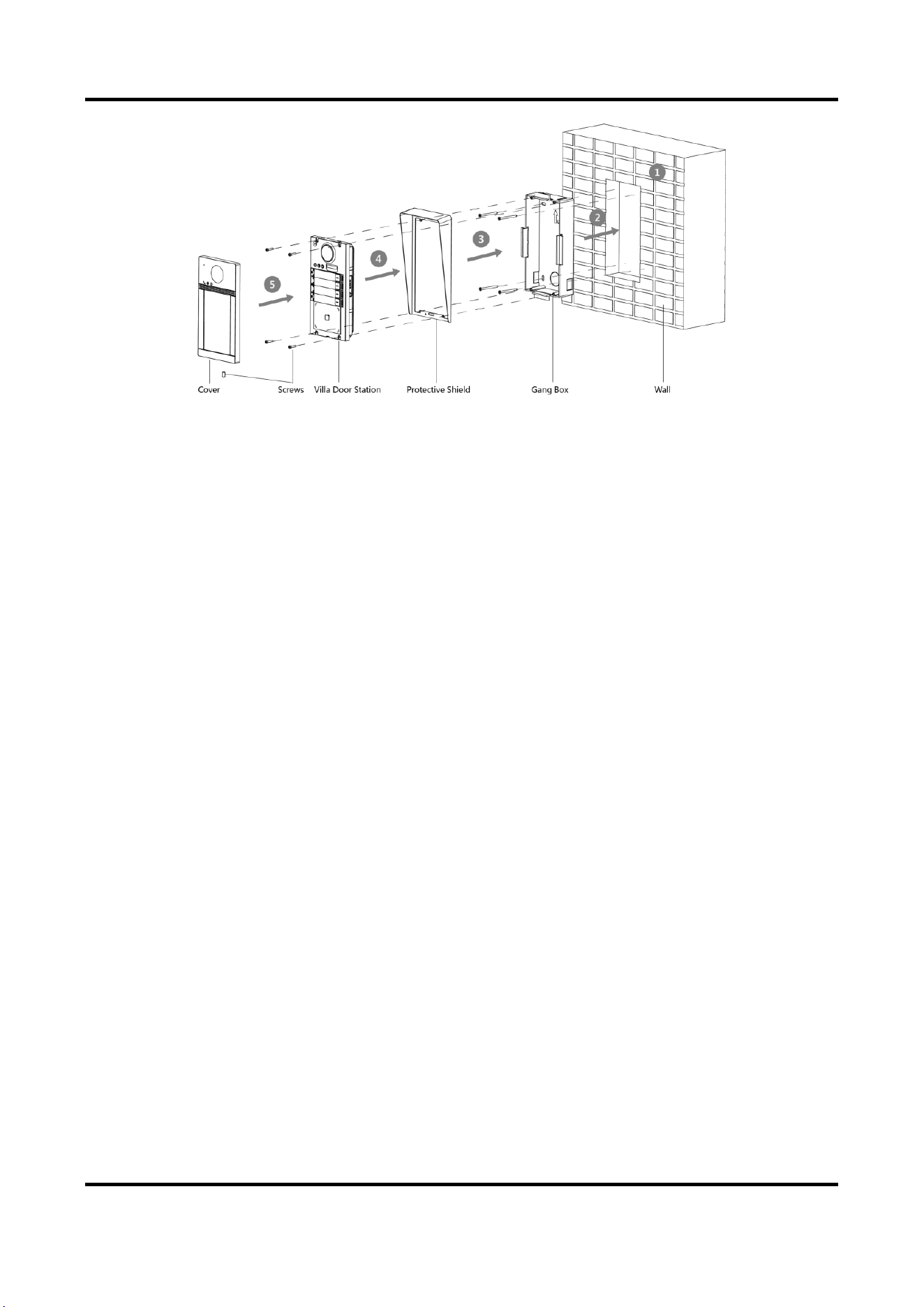
3.4 Flush Mounting with Protective Shield
Before You Start
●
Tools that you need to prepare for installation: Drill (ø2.846) and gradienter.
●
Purchase the protective shield before installation.
Steps
1. Stick the mounting template on the wall. Drill the hole according to the mounting template.
Remove the template from the wall.

Video Intercom Villa Door Station User Manual
15
Figure 3-6 Mounting Template
Note
The suggested size of hole is 175 mm × 84 mm × 19 mm.
2. Install the gang box into the hole with 4 screws.
3. Align the protective shield with the gang box.
4. Insert the device to the gang box. Secure the device with 4 supplied screws.
5. Fix the cover onto the device with the screw.
Video Intercom Villa Door Station User Manual
16
Figure 3-7 Flush Mounting with Protective Shield
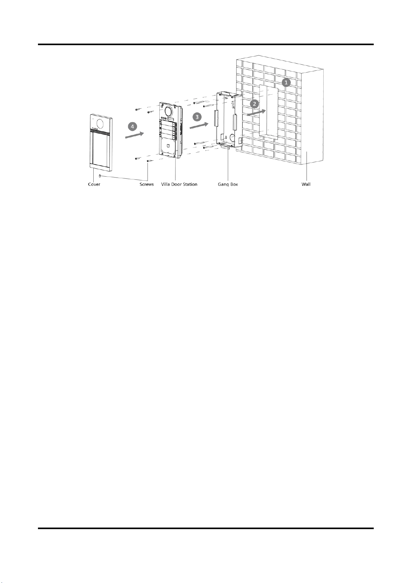
3.5 Flush Mounting without Protective Shield
Before You Start
Tools that you need to prepare for installation: Drill (ø2.846) and gradienter.
Steps
1. Stick the mounting template on the wall. Drill the hole according to the mounting template.
Remove the template from the wall.
Video Intercom Villa Door Station User Manual
17
Figure 3-8 Mounting Template
Note
The suggested size of hole is 175 mm × 84 mm × 19 mm.
2. Secure the gang box into the hole with 4 screws.
3. Insert the device to the gang box. Secure the device with 4 supplied screws.
4. Fix the cover onto the device with the screw.
Video Intercom Villa Door Station User Manual
18
Figure 3-9 Flush Mounting without Protective Shield

Video Intercom Villa Door Station User Manual
19
Chapter 4 Activation
4.1 Activate Device via Web
You are required to activate the device first by setting a strong password for it before you can use
the device.
Default parameters of the door station are as follows:
●
Default IP Address: 192.0.0.65.
●
Default Port No.: 8000.
●
Default User Name: admin
Steps
1. Power on the device, and connect the device to the network.
2. Enter the IP address into the address bar of the web browser, and click Enter to enter the
activation page.
Note
The computer and the device should belong to the same subnet.
3. Create and enter a password into the password field.
4. Confirm the password.
5. Click OK to activate the device.
4.2 Activate Device via Client Software
You can only configure and operate the door station after creating a password for the device
activation.
Default parameters of door station are as follows:
●
Default IP Address: 192.0.0.65.
●
Default Port No.: 8000.
●
Default User Name: admin.
Steps
1. Run the client software, click Maintenance and Management → Device Management → Device
to enter the page.
2. Click Online Device.
3. Select an inactivated device and click Activate.
4. Create a password, and confirm the password.
Video Intercom Villa Door Station User Manual
20
Note
We highly recommend you to create a strong password of your own choosing (using a minimum
of 8 characters, including at least three kinds of following categories: upper case letters, lower
case letters, numbers, and special characters) in order to increase the security of your product.
And we recommend you change your password regularly, especially in the high security system,
changing the password monthly or weekly can better protect your product.
5. Click OK to activate the device.
Note
●
When the device is not activated, the basic operation and remote operation of device cannot
be performed.
●
You can hold the Ctrl or Shift key to select multiple devices in the online devices, and click the
Activate button to activate devices in batch.
4.3 Edit Network Parameters
To operate and configure the device via LAN (Local Area Network), you need connect the device in
the same subnet with your PC. You can edit network parameters via iVMS-4200 client software.
Steps
1. Select an online activated device and click the Modify Netinfo.
2. Edit the device IP address and gateway address to the same subnet with your computer.
3. Enter the password and click OK to save the network parameters modification.
Note
●
The default port No. is 8000.
●
The default IP address of the door station is 192.0.0.65.
●
After editing the network parameters of device, you should add the devices to the device list
again.
Video Intercom Villa Door Station User Manual
21
Chapter 5 Remote Configuration via Web
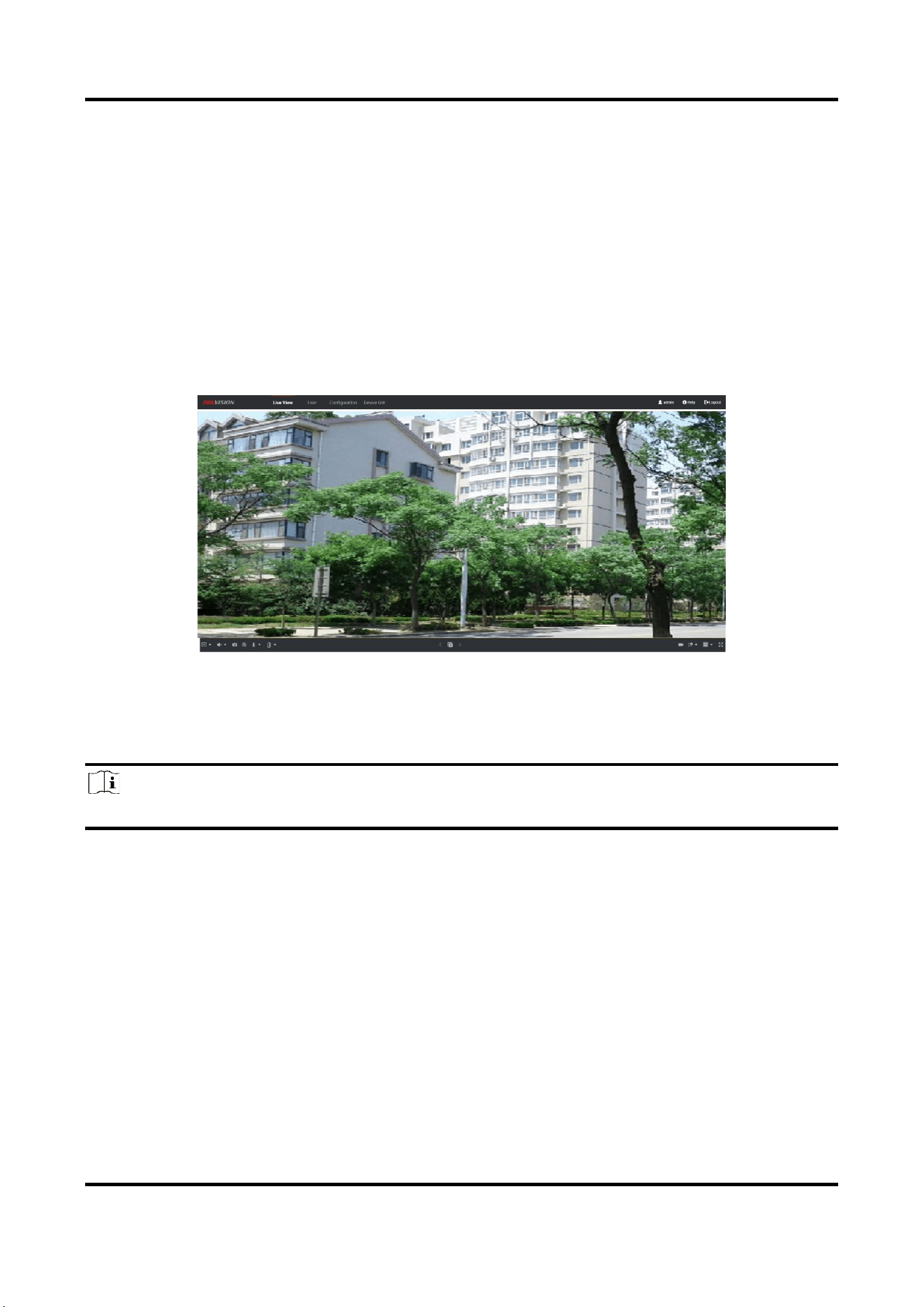
5.1 Live View
In the browser address bar, enter the IP address of the device, and press the Enter key to enter the
login page.
Enter the user name and password and click Login to enter the Live View page. Or you can click
Live View to enter the page.
Figure 5-1 Live View
●
You can start/stop live view, capture, record, audio on/off, two-way audio, etc.
●
The stream type can be set as main stream or sub stream.
●
For IE (Internet Explorer) or Google users, the device support two-way audio communication.
Note
Live View function may vary with different models. Please refer to the actual product.
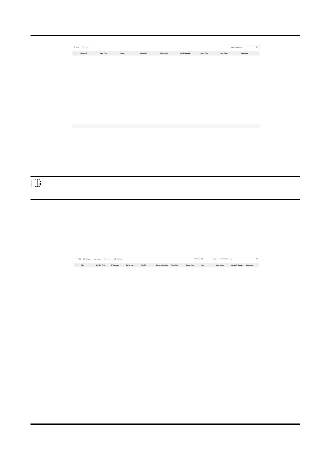
5.2 User Management
You can add, delete or search the information of the user.
Click User to enter the settings page.
Video Intercom Villa Door Station User Manual
22
Figure 5-2 User Management
●
Click Add and enter the Name, Floor No. and Room No. to add.
●
Click Edit to modify the information of the user.
●
Check the box of the user and click Delete to delete the selected user.
●
Enter the keyword and click search icon. The information will display in the list.
Note
User management function may vary with different models. Please refer to the actual product.
5.3 Device Management
You can manage the linked device on the page.
Click Device Management to enter the settings page.
Figure 5-3 Device Management
Add Device
●
Click Add to add the indoor station or sub door station. Enter the parameters and click OK to
add.
●
Click Import. Enter the information of the device in the template to import devices in batch.
Video Intercom Villa Door Station User Manual
23
Export
Click Export to export the information to the PC.
Delete
Select the device and click Delete to remove the selected device from the list.
Refresh
Click Refresh to get the device information.
Optional: Set Device Information.
●
Click to edit device information.
●
Click to delete device information from the list.
●
Select Status and Device Type to search devices.
5.4 Parameters Settings
Click Configuration to set the parameters of the device.
Remote configuration in iVMS-4200 and Batch Configuration Tool is the same as that in Web. Here
takes the configuration in web for example.
Note
Run the browser, click → Internet Options → Security to disable the Protected Mode.
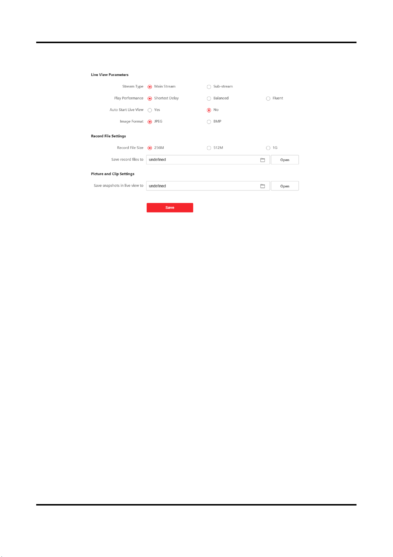
5.4.1 Local Parameters Settings
You can configure the parameters of the live view, record files and captured pictures. The record
files and captured pictures are the ones you record and capture by using the web browser. You
can also set and view the saving paths of the captured pictures and recorded videos on the PC that
Video Intercom Villa Door Station User Manual
24
running the web browser.
Figure 5-4 Local Parameters
Live View Parameters
Stream Type
Set the stream type as Main Stream or Sub-stream.
Play Performance
Set the live view performance to Shortest Delay, Balanced or Fluent.
Auto Start Live View
Check Yes to enable the function.
Image Format
Select the image format for picture capture.
Click Save to enable the settings.
Record File Parameters
Record File Size
Select the packed size of the manually recorded and downloaded video files to 256M, 512M or
1G. After the selection, the maximum record file size is the value you selected.
Save record files to
Set the saving path for the manually recorded video files.
Click Save to enable the settings.
Picture and Clip Settings
Save snapshots in live view to

Video Intercom Villa Door Station User Manual
25
Set the saving path of the manually captured pictures in live view mode.
Note
You can click Browse to change the directory for saving the clips and pictures, and click Open to
open the set folder of clips and picture saving.
Click Save to enable the settings.
5.4.2 System Settings
Follow the instructions below to configure the system settings, include System Settings,
Maintenance, Security, and User Management, etc.
Click System to enter the settings page.
Basic Information
Click System Settings → Basic Information to enter the settings page. On the page, you can edit
Device Name and Device No. Set the Language and System Type according to your needs.
Click Save to enable the settings.
Time Settings
Click System Settings → Time Settings to enter the settings page. Select the Time Zone of your
location from the drop-down list.
●
Enable NTP, set the Server Address, NTP Port and Interval.
●
Enable Manual Time Sync., set the time manually or check the Sync. with computer time.
Click Save to enable the settings.
DST
Click System Settings → DST to check Enable DST. Set the parameters according to your needs and
click Save to enable the settings.
About
Click System Settings → About and click Open Source Software Licenses to view the details.
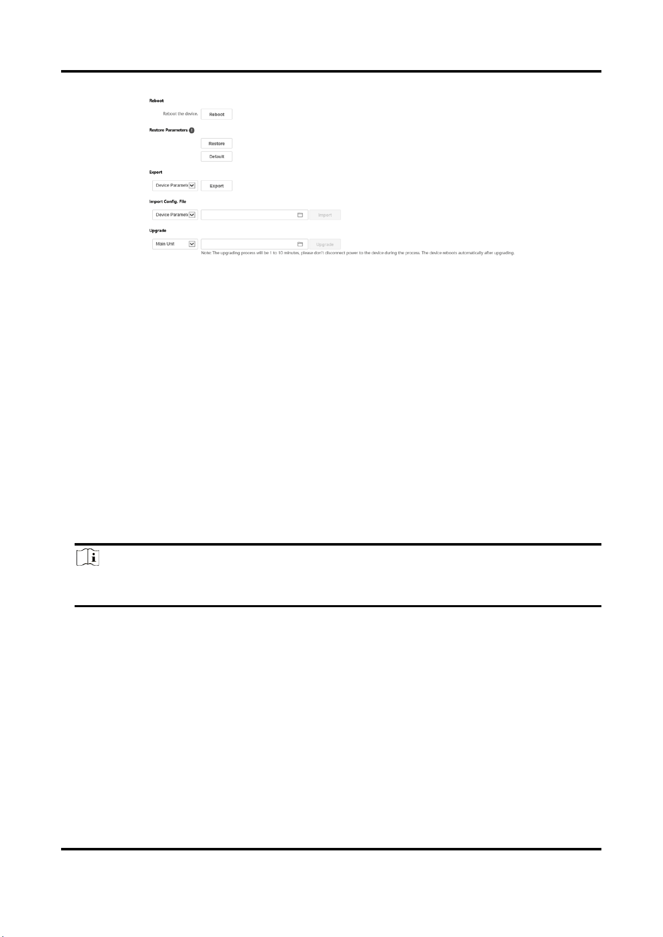
Maintenance
Click Maintenance → Upgrade & Maintenance to enter the settings page.
Video Intercom Villa Door Station User Manual
26
Figure 5-5 Maintenance
●
Reboot: Click Reboot to reboot the device.
Restore
Click Restore to reset all the parameters, except the IP parameters and user information, to
the default settings.
Default
Click Default to restore all parameters to default settings.
●
Export parameters:
1. Select Device Parameters, and click Export to pop up the dialog box.
2. Set and confirm the encryption password.
3. Click OK to export parameters.
●
Import Config. File:
1. Click browse icon to select the configuration file.
2. Click Import and enter the encryption password to import.
●
Upgrade: Click browse icon to select the upgrade file.
Note
The upgrading process will last 1 to 10 minutes, do not power off during the upgrading. The
device reboots automatically after upgrading.
Security Service
Click Security → Security Service to enter the settings page. On the page, you can enable SSH
according to your actual needs.
Click Save to enable the settings.
User Management
Click User Management to enter the settings page.
Administrator can edit the permission for the users.
Video Intercom Villa Door Station User Manual
27
Note
We highly recommend you to create a strong password of your own choosing (using a minimum of
8 characters, including at least three kinds of following categories: upper case letters, lower case
letters, numbers, and special characters) in order to increase the security of your product. And we
recommend you change your password regularly, especially in the high security system, changing
the password monthly or weekly can better protect your product.
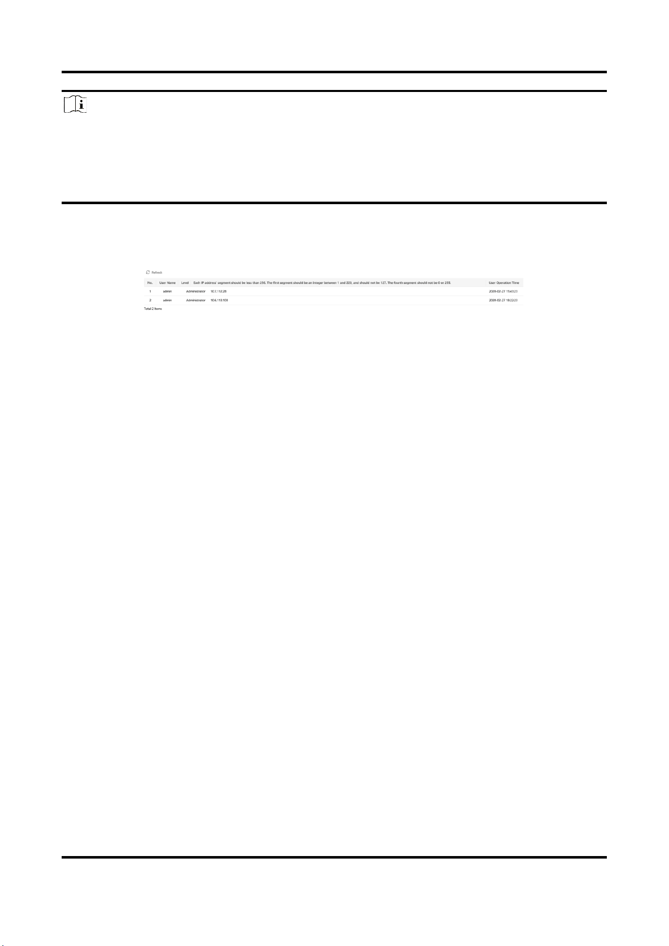
Online Users
Click User Management → Online Users to enter the page.
Figure 5-6 Online Users
Click Refresh to get the present information.
Arming/Disarming Information
Click User Management → Arming/Disarming Information to view the information. Click Refresh
to get the present information.
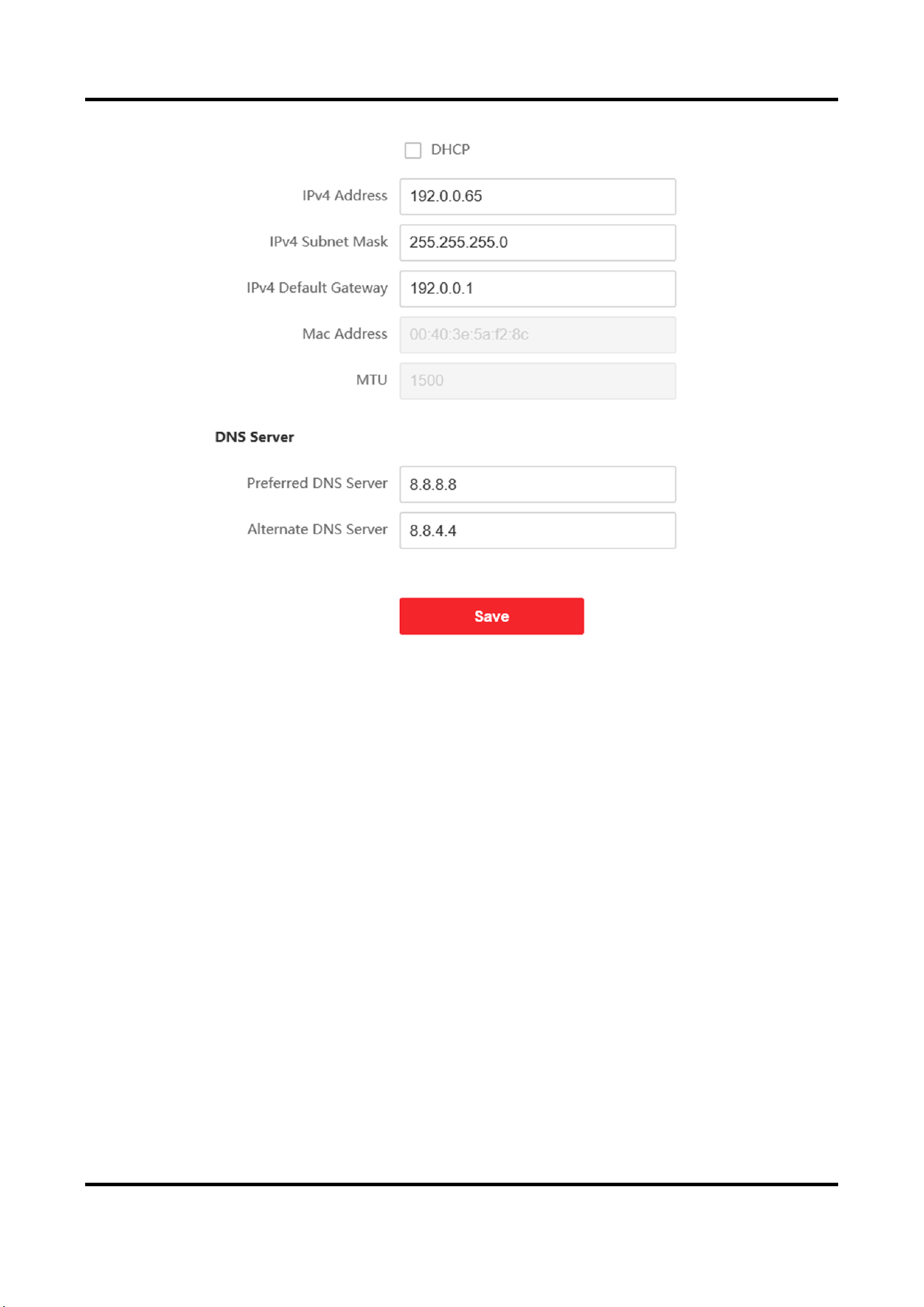
5.4.3 Network Settings
TCP/IP Settings
TCP/IP settings must be properly configured before you operate the device over network. The
device supports IPv4.
Steps
1. Click Network → Basic Settings → TCP/IP to enter the settings page.
Video Intercom Villa Door Station User Manual
28
Figure 5-7 TCP/IP Settings
2. Configure the network parameters.
–
Check DHCP, the device will get the parameters automatically.
–
Set the IPv4 Address, IPv4 Subnet Mask and IPv4 Default Gateway manually.
3. Configure the corresponding DNS server parameters.
4. Click Save to enable the settings.
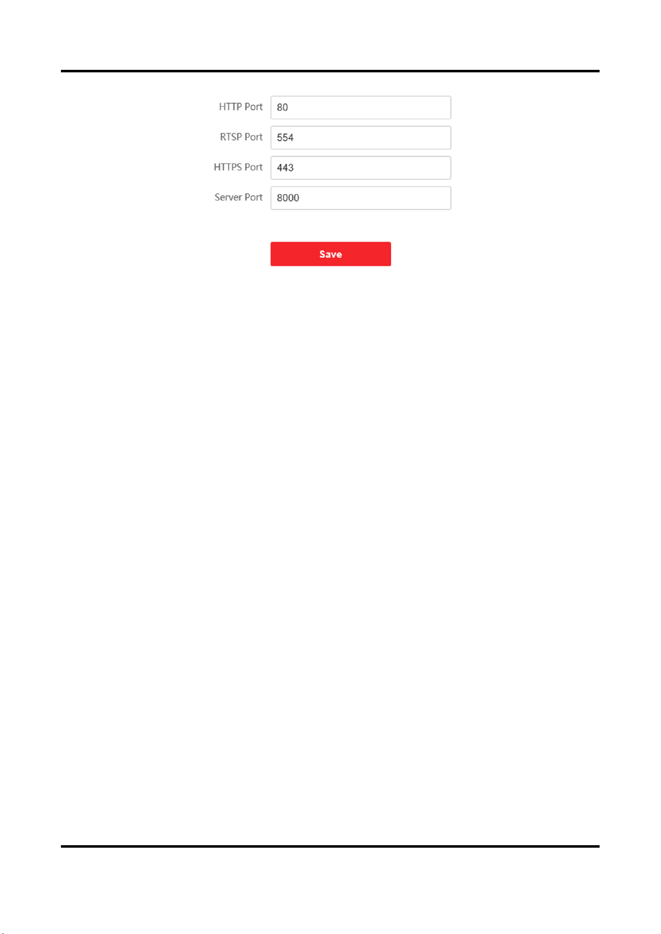
Port Settings
Steps
1. Click Network → Basic Settings → Port to enter the settings page.
Video Intercom Villa Door Station User Manual
29
Figure 5-8 Port Settings
2. Set the ports of the device.
HTTP Port
The default port number is 80, and it can be changed to any port No. which is not occupied.
HTTPS Port
The default port number is 443, and it can be changed to any port No. which is not occupied.
RTSP Port
The default port number is 554.
Server Port
The default server port number is 8000, and it can be changed to any port No. ranges from
2000 to 65535.
3. Click Save to enable the settings.
SIP Setting
Steps
1. Click Network → Basic Settings → SIP to enter the settings page.
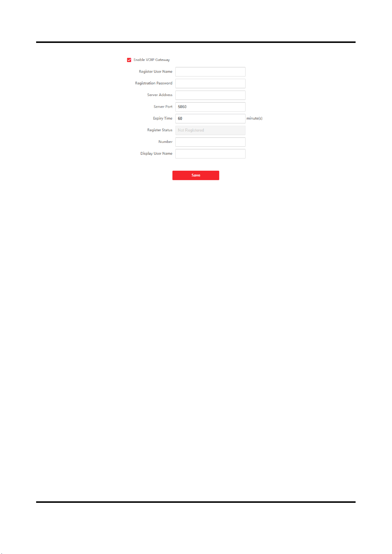
Video Intercom Villa Door Station User Manual
30
Figure 5-9 SIP Settings
2. Check Enable VOIP Gateway.
3. Configure the SIP parameters.
4. Click Save to enable the settings.
FTP Settings
Steps
1. Click Network → Advanced → FTP to enter the settings page.
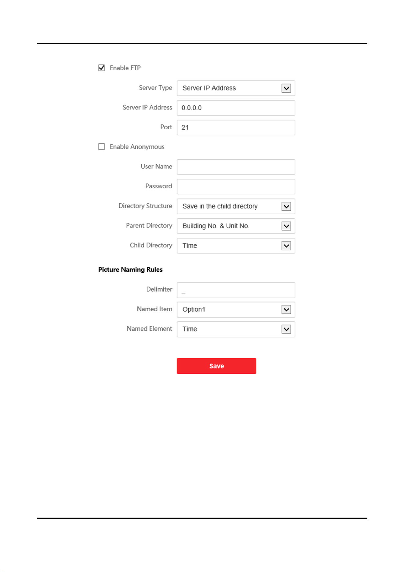
Video Intercom Villa Door Station User Manual
31
Figure 5-10 FTP Settings
2. Check Enable FTP.
3. Select Server Type.
4. Input the Server IP Address and Port.
5. Configure the FTP Settings, and the user name and password are required for the server login.
6. Set the Directory Structure, Parent Directory and Child Directory.
7. Set the picture naming rules.
8. Click Save to enable the settings.
Video Intercom Villa Door Station User Manual
32
Platform Access
Platform access provides you an option to manage the devices via platform.
Steps
1. Click Network → Advanced Settings → Platform Access to enter the settings page.
2. Check the checkbox of Enable to enable the function.
3. Select the Platform Access Mode.
Note
Hik-Connect is an application for mobile devices. With the App, you can view live image of the
device, receive alarm notification and so on.
4. Create a Stream Encryption/Encryption for the device.
Note
6 to 12 letters (a to z, A to Z) or numbers (0 to 9), case sensitive. You are recommended to use a
combination of no less than 8 letters or numbers.
5. Click Save to enable the settings.
5.4.4 Video & Audio Settings
Video Parameters
Steps
1. Click Video/Audio → Video to enter the settings page.
Video Intercom Villa Door Station User Manual
33
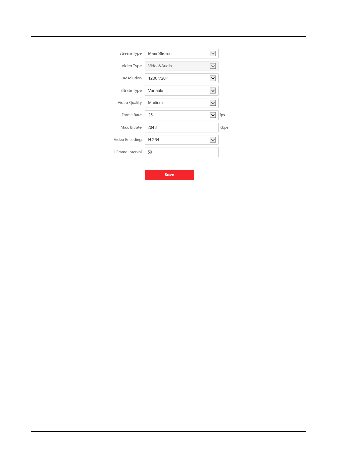
Figure 5-11 Video Parameters
2. Select the Stream Type.
3. Configure the video parameters.
Stream Type
Select the stream type to main stream or sub stream.
Video Type
Select the stream type to video stream, or video & audio composite stream. The audio signal
will be recorded only when the Video Type is Video & Audio.
Resolution
Select the resolution of the video output.
Bitrate Type
Select the bitrate type to constant or variable.
Video Quality
When bitrate type is selected as Variable, 6 levels of video quality are selectable.
Frame Rate
Set the frame rate. The frame rate is to describe the frequency at which the video stream is
updated and it is measured by frames per second (fps). A higher frame rate is advantageous
when there is movement in the video stream, as it maintains image quality throughout.
Max. Bitrate
Set the max. bitrate from 32 to 16384 Kbps. The higher value corresponds to the higher video
quality, but the better bandwidth is required.
Video Encoding
Video Intercom Villa Door Station User Manual
34
The device supports H.264.
I Frame Interval
Set I Frame Interval from 1 to 400.
4. Click Save to save the settings.
Audio Parameters
Steps
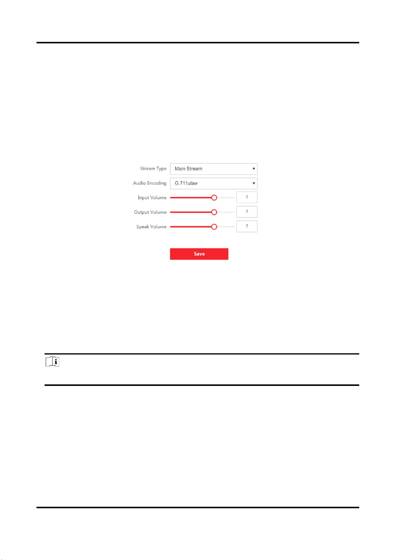
1. Click Video/Audio → Audio to enter the settings page.
Figure 5-12 Audio Settings
2. Configure the stream type and the audio encoding type.
Stream Type
Select the stream type to main stream or sub stream.
Audio Encoding
The device support G.711ulaw and G.711 alaw.
3. Adjust the Input Volume, Output Volume and Speak Volume.
Note
Available range of volume: 0 to 10.
4. Click Save to save the settings.
Video Intercom Villa Door Station User Manual
35
5.4.5 Image Settings
Display Settings
Configure the image adjustment, backlight settings and other parameters in display settings.
Steps
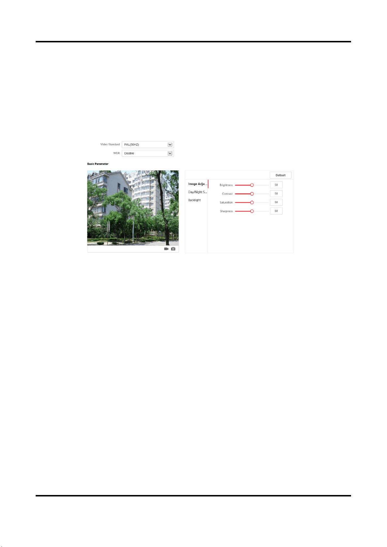
1. Click Image → Display Settings to enter the display settings page.
Figure 5-13 Display Settings
2. Select the Format.
3. Set the display parameters.
WDR
Wide Dynamic Range can be used when there is a high contrast of the bright area and the
dark area of the scene.
Brightness
Brightness describes bright of the image, which ranges from 1 to 100.
Contrast
Contrast describes the contrast of the image, which ranges from 1 to 100.
Saturation
Saturation describes the colorfulness of the image color, which ranges from 1 to 100.
Sharpness
Sharpness describes the edge contrast of the image, which ranges from 1 to 100.
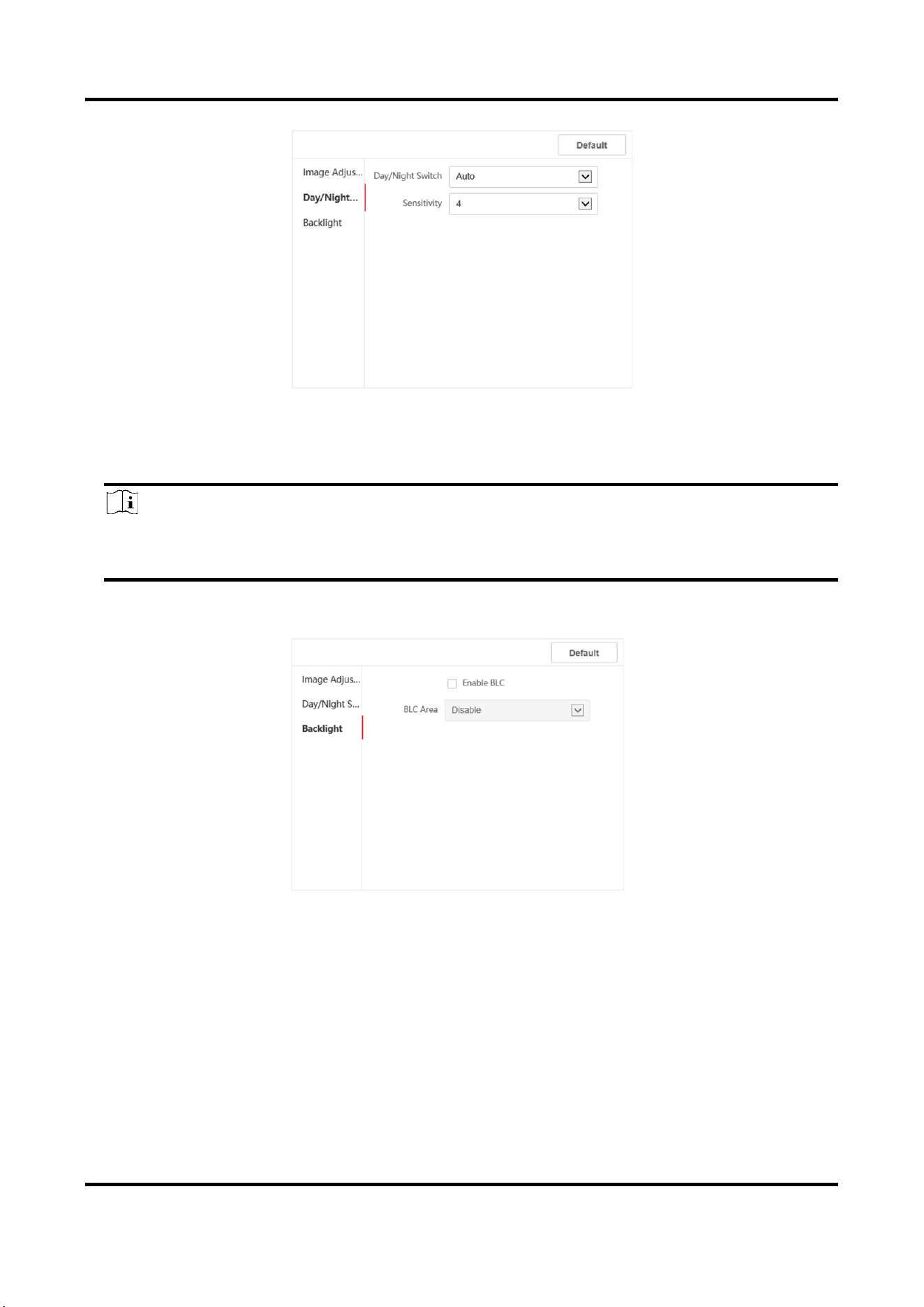
4. Set the Day/Night Mode.
Video Intercom Villa Door Station User Manual
36
Figure 5-14 Day/Night Mode
Set Day Mode or Night Mode manually.Set the mode as Auto and edit the sensitivity according to
your needs.Set the mode as Scheduled-Switch. Set the start time and end time.
Note
Daytime is from configured start time to configured time. The rest of the time is set as night by
default.
5. Set the backlight parameters.
Figure 5-15 Backlight
1) Check the checkbox to enable BLC.
2) Select BLC Area.
6. Click Save to enable the settings.
OSD Settings
You can customize the camera name, time/date format, display mode, and OSD size displayed on
Video Intercom Villa Door Station User Manual
37
the live view.
Steps
1. Click Image → OSD Settings to enter the settings page.
2. Check the corresponding checkbox to select the display of camera name, date or week if
required.
3. Edit the Camera Name.
4. Select from the drop-down list to set the Time Format and Date Format.
5. Adjust the OSD position.
6. Click Save to enable the settings.
Target Cropping
Steps
1. Click Image → Crop to enter the page.
2. Check Enable Target Cropping to enable the function.
3. Click to crop photo.
4. Click to crop video.
5. Select Cropping Resolution.
6. Click Save.
Note
●
You can select Cropping Resolution as 704*576, 1280*720, or 1920*1080.
●
You can zoom in or zoom out the image by selecting Cropping Resolutionafter clicking Save.
5.4.6 Event Settings
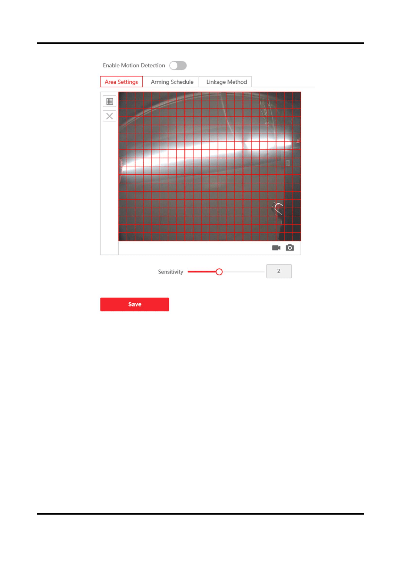
Motion Detection
Motion detection detects the moving objects in the configured security area, and a series of actions
can be taken when the alarm is triggered.
Steps
1. Click Event → Motion to enter the settings page.
Video Intercom Villa Door Station User Manual
38
Figure 5-16 Motion Detection
2. Slide Enable Motion Detection to enable the function.
3. Click Draw Area. Click and drag the mouse on the live video to draw a motion detection area.
Click Save to save the settings.
Clear Area
Click X to clear all of the areas.
Adjust Sensitivity
Move the slider to set the sensitivity of the detection.
4. Click Arming Schedule to edit the arming schedule.
5. Click on the time bar and drag the mouse to select the time period. Click Save to save the
settings.
Delete Schedule
Click Delete to delete the current arming schedule.
6. Click Linkage Method to enable the linkages.
Notify Security Center
Send an exception or alarm signal to the remote management software when an event
Video Intercom Villa Door Station User Manual
39
occurs.
7. Click Save to enable the settings.
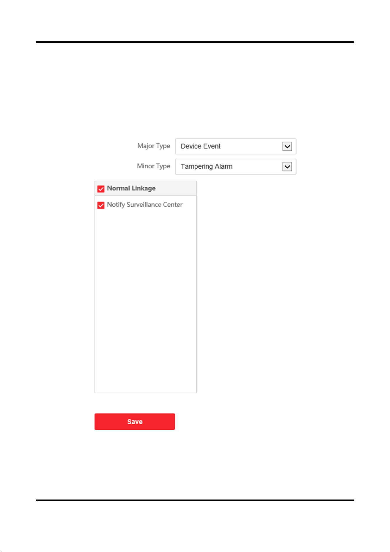
Event Linkage
Steps
1. Click Event → Basic Event → Event Linkage to enter the settings page.
Figure 5-17 Event Linkage
2. Select the Major Type as Device Event or Door Event.
3. Select the type of the Normal Linkage for the event.
Video Intercom Villa Door Station User Manual
40
4. Click Save to enable the settings.
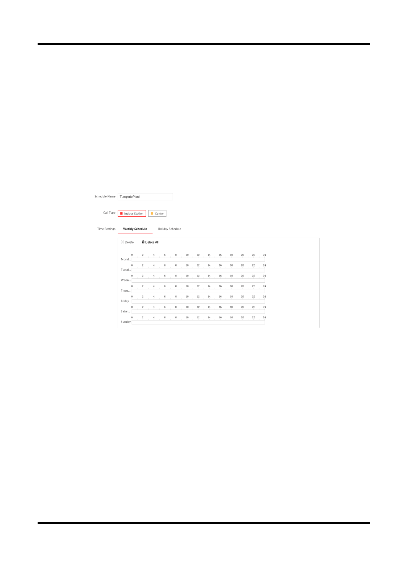
5.4.7 Schedule Settings
You can create call schedule, or else the device will call indoor station all day by default.
Steps
1. Click Schedule → Video Intercom → Call Schedule.
2. Click the next row below Enable Indoor Station All Day by Default.
3. Enter Schedule Name.
4. Select Call Type.
5. Set Weekly Schedule.
1) Click Weekly Schedule.
Figure 5-18 Weekly Schedule
2) Drag mouse to set the schedule according to the actual needs.
3) Optional: Click the copy icon to copy the schedule to other days according to the actual
needs.
4) Click Save.
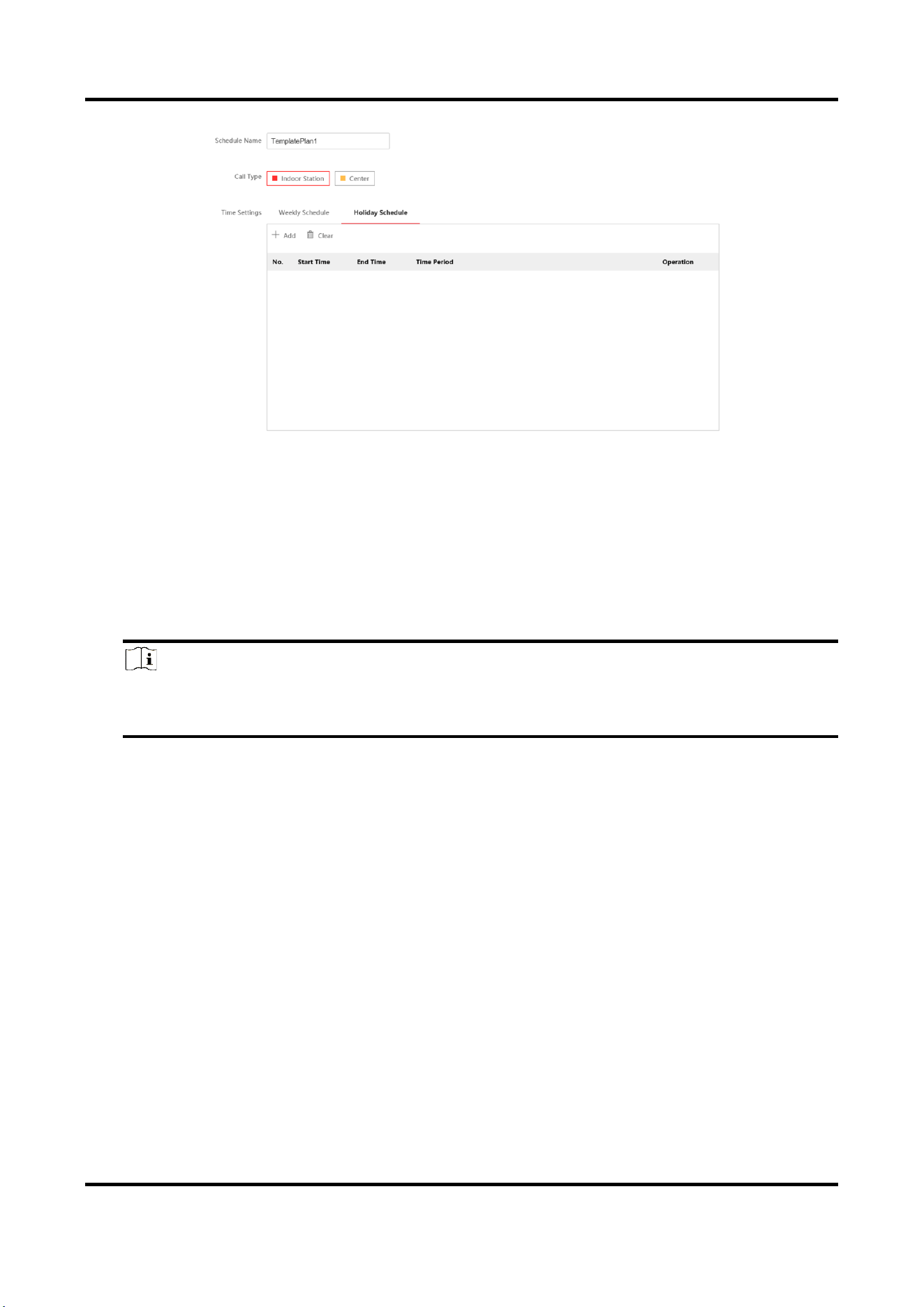
6. Set Holiday Schedule.
1) Click Holiday Schedule.
Video Intercom Villa Door Station User Manual
41
Figure 5-19 Holiday Schedule
2) Click Add.
3) Set Start Time and End Time.
4) Select Call Type.
5) Drag mouse to set the schedule according to the actual needs.
6) Click OK.
7) You can edit or delete the schedule according to the actual needs.
8) Click Save.
Note
The holiday schedule have higher priority than weekly schedule when you set the two
schedule at the same time.
5.4.8 Intercom Settings
Device No. Settings
Steps
1. Click Device No. to enter the page.
Video Intercom Villa Door Station User Manual
42
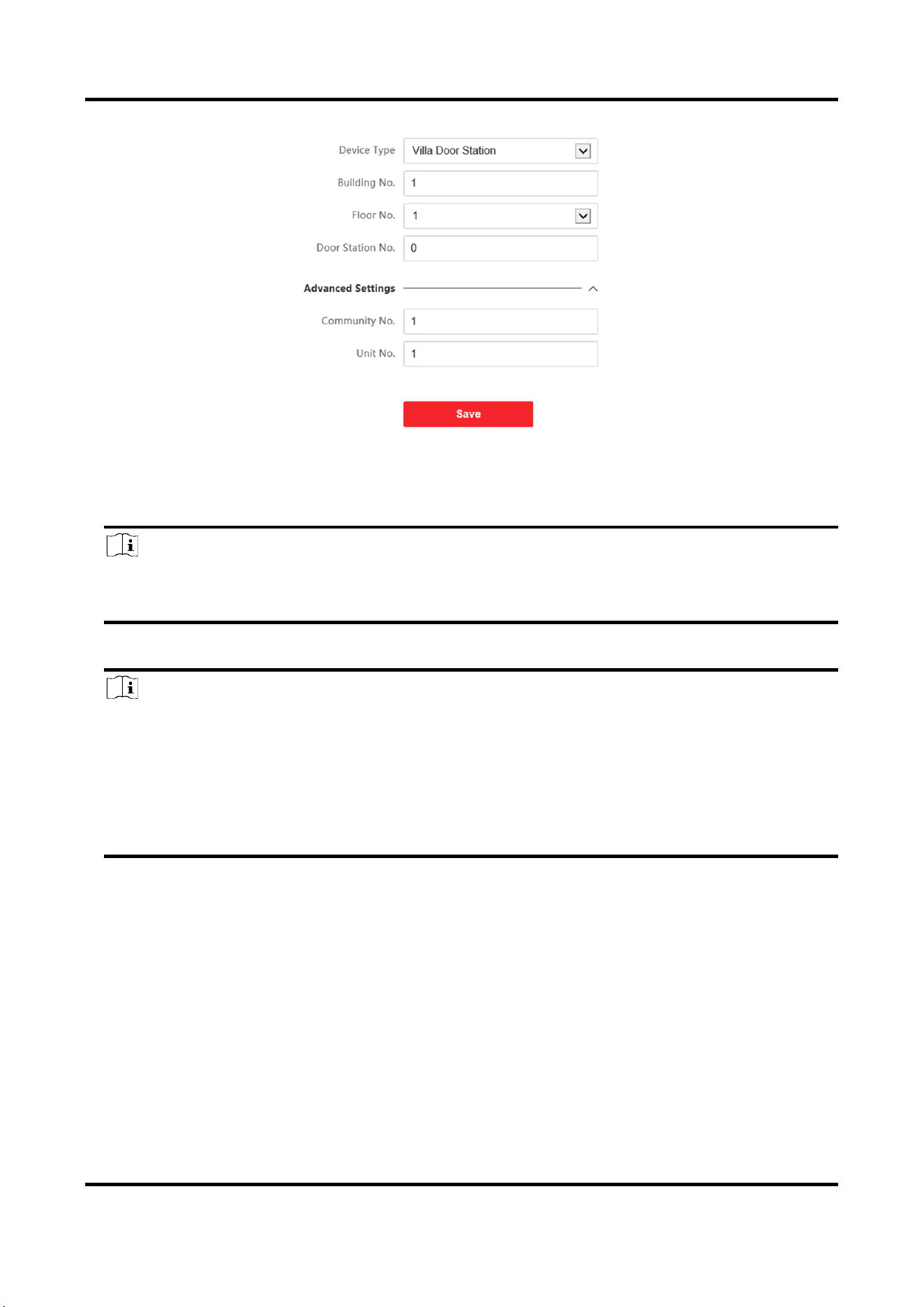
Figure 5-20 Villa Door Station No. Settings
2. Select the device type from the drop-down list, and set the corresponding information including
Building No., Floor No., Door Station No., Community No. and Unit No.
Note
When you select Doorphone as Device Type, only Community No., Building No. and Unit No.
can be set.
3. Click Save to enable the device number configuration.
Note
●
For main door station (D series or V series), the No. is 0.
●
For sub door station (D series or V series), the No. cannot be 0. The No.of sub door station
ranges from 1 to 99.
●
For each villa or building, at least one main door station (D series or V series) should be
configured, and one sub door stations (D series or V series) can be customized.
●
For one main door station (D series or V series), up to 8 sub door stations can be configured.
Linked Network Settings
Steps
1. Go to Intercom → Session Settings to enter the settings page.
2. Set Register Number and Registration Password.
3. Set Main Station IP and VideoIntercom Server IP.
4. Enable Protocol 1.0.
5. Click Save to enable the settings.
Video Intercom Villa Door Station User Manual
43
Time Parameters
Go to Intercom → Time Parameters to enter the page.
Configure Max. Call Duration, Max. Message Duration, Max. Ring Duration, and click Save.
Note
●
Max. call duration between the module indoor station and client ranges from 90 s to 120 s. The
call will end automatically when the actual calling duration is longer than the configured one.
●
Max. message duration ranges from 30 s to 60 s. The message will end automatically when the
actual message duration is longer than the configured one.
●
Max. ring duration refers to the maximum duration of the module indoor station when it is
called without being accepted. Max. ring duration ranges from 65 s to 255 s.
Ring-Back Tone Settings
Click Intercom → Ringbacktone Settings to enter the settings page.
Click Add to select the ring tone from PC.
Note
Available Audio Format: WAV、AAC, Size: Less than 600 KB, Sample Rate: 8000Hz, Mono.
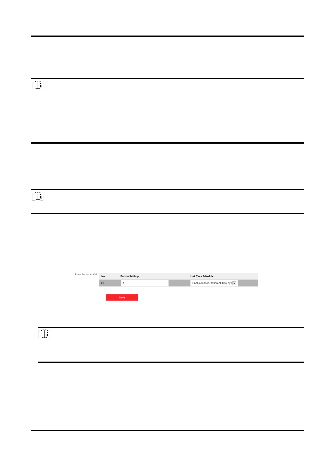
Press Button to Call
Steps
1. Go to Intercom → Press Button to Call to enter the settings page.
Figure 5-21 Press Button to Call
2. Edit room No. in the button settings and select Link Time Schedule.
Note
●
The number of buttons may vary with different models. Please refer to the actual product.
●
The schedule settings refers to Schedule Settings for details.
3. Click Save to enable the settings.
Video Intercom Villa Door Station User Manual
44
Number Settings
Link the room No. and SIP numbers.
Click Number Settings to enter the page.
Figure 5-22 Number Settings
Click Add, set the Room No. and SIP numbers in the pop-up dialog box.
5.4.9 Access Control Settings
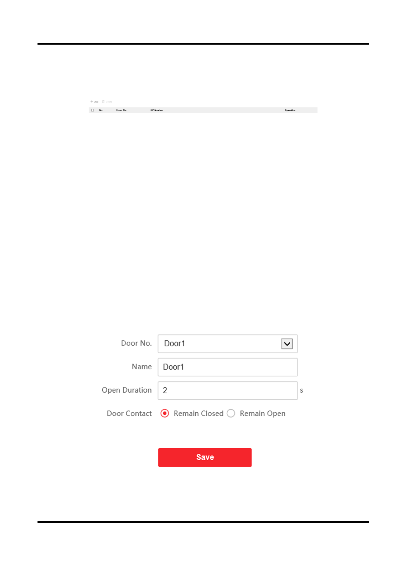
Door Parameters
Steps
1. Click Access Control → Door Parameters to enter the settings page.
Figure 5-23 Door Parameters
Video Intercom Villa Door Station User Manual
45
2. Select the door and edit the door name.
3. Edit Open Duration.
4. Set door contact status.
5. Click Save to enable the settings.
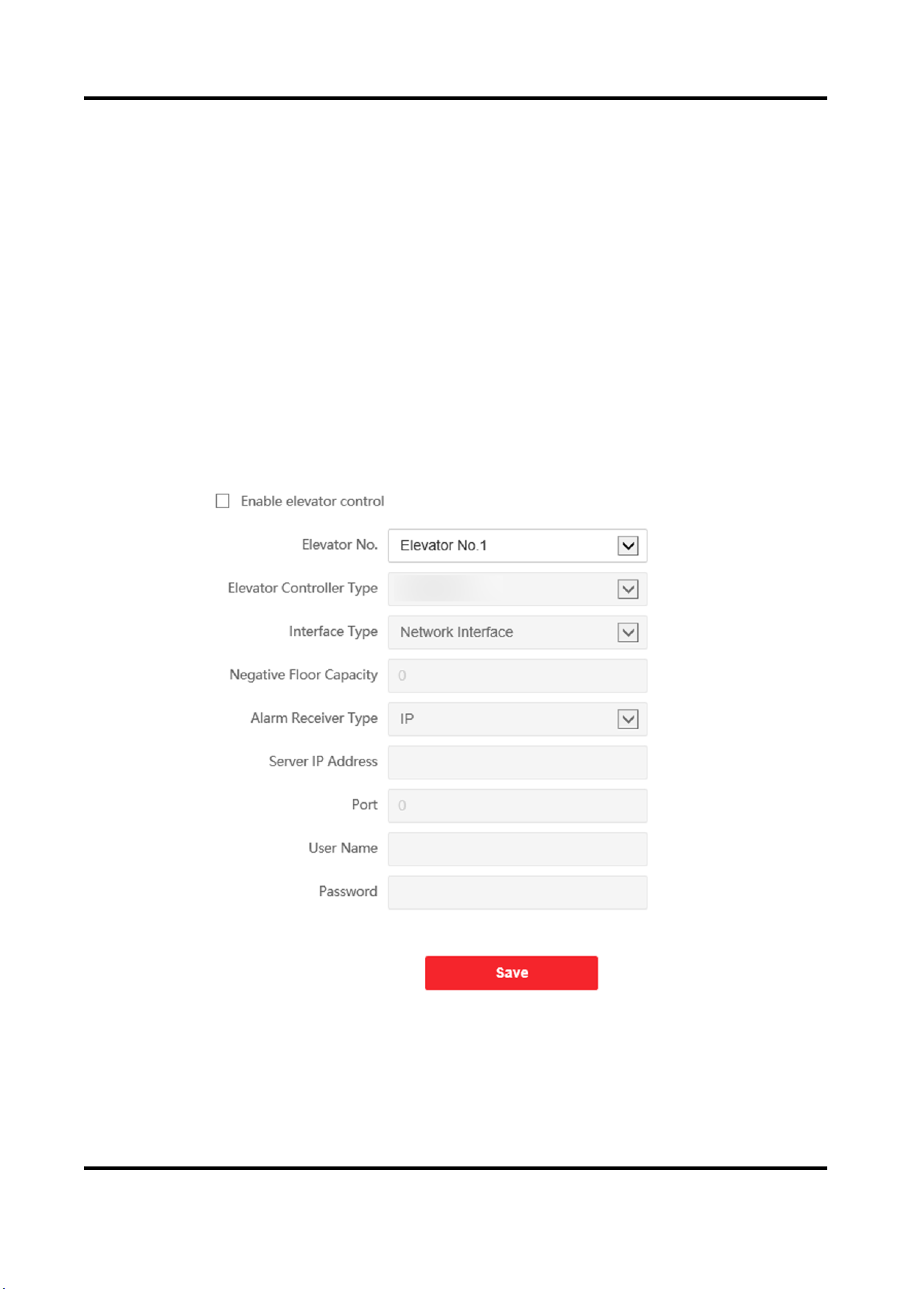
Elevator Control
Before You Start
●
Make sure your door station is in the mode of main door station. Only the main door station
support elevator control function.
●
Make sure your door station has been connected to the elevator controller via RS-485 wire if
you want to use RS-485 interface.
Steps
1. Click Access Control → Elevator Control to enter the corresponding configuration page.
Figure 5-24 Elevator Control
2. Check to enable elevator control function.
3. Select an Elevator No., and select an elevator controller type for the elevator.
4. Set the Negative Floor.

Video Intercom Villa Door Station User Manual
46
5. Select the Interface Type as RS-485 or Network Interface. And enable the elevator control.
–
If you select RS-485, make sure you have connected the door station to the elevator
controller with RS-485 wire.
–
If you select Network interface, enter the elevator controller's IP address, port No., user
name, and password.
6. Click Save to enable the settings.
Note
●
Up to 4 elevator controllers can be connected to one door station.
●
Up to 10 negative floors can be added.
●
Make sure the interface types of elevator controllers, which are connected to the same door
station are consistent.

Video Intercom Villa Door Station User Manual
47
Chapter 6 Configuration via Client Software
6.1 Device Management
Device management includes device activation, adding device, editing device, and deleting device,
and so on.
After running the iVMS-4200, video intercom devices should be added to the client software for
remote configuration and management.
6.1.1 Add Online Device
Before You Start
Make sure the device to be added is in the same subnet with your computer. Otherwise, please
edit network parameters first.
Steps
1. Click Online Device to select an active online device.
2. Click Add.
3. Enter corresponding information, and click Add.
Video Intercom Villa Door Station User Manual
48
Figure 6-1 Add to the Client
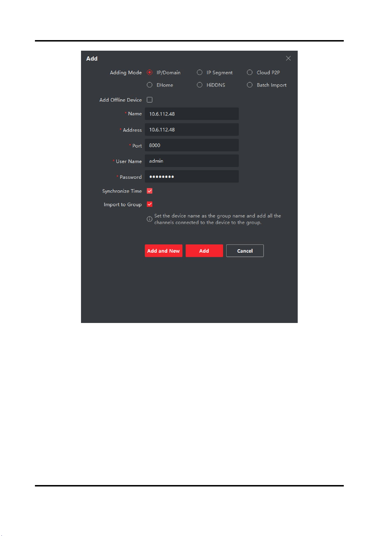
6.1.2 Add Device by IP Address
Steps
1. Click +Add to pop up the adding devices dialog box.
2. Select IP/Domain as Adding Mode.
3. Enter corresponding information.
4. Click Add.

Video Intercom Villa Door Station User Manual
49
6.1.3 Add Device by IP Segment
You can add many devices at once whose IP addresses are among the IP segment.
Steps
1. Click +Add to pop up the dialog box.
2. Select IP Segment as Adding Mode.
3. Enter corresponding information, and click Add.
6.2 Live View via Door Station
Steps
1. On the main page of the client software, click Main View to enter the Live View page.
2. In the left list of the window, double-click the device IP or click the play icon to live view.
3. Optional: On the Live View page, control-click and select Capture to get the picture of the live
view.
6.3 Organization Management
On the main page of the Client Software, click PersonalManagement to enter the
configuration page.
6.3.1 Add Organization
Steps
1. In the organization list on the left, click +Add.
2. Enter the Organization Name as desired.
3. Click OK to save the adding.
4. Optional: You can add multiple levels of organizations according to the actual needs.
1) You can add multiple levels of organizations according to the actual needs.
2) Then the added organization will be the sub-organization of the upper-level organization.
Note
Up to 10 levels of organizations can be created.
6.3.2 Modify and Delete Organization
You can select the added organization and click to modify its name.
You can select an organization, and click X button to delete it.
Video Intercom Villa Door Station User Manual
50
Note
●
The lower-level organizations will be deleted as well if you delete an organization.
●
Make sure there is no person added under the organization, or the organization cannot be
deleted.
6.4 Person Management
After adding the organization, you can add person to the organization and manage the added
person such as issuing cards in batch, importing and exporting person's information in batch, etc.
Note
●
Up to 2,000 persons can be added.
●
Up to 5 cards can be added to each person.
6.4.1 Add Person
Person information is necessary for the video intercom system. And when you set linked device for
the person, the intercom between intercom devices can be realized.
Steps
1. Select an organization in the organization list and click Add on the Person panel to pop up the
adding person dialog.
Note
The Person No. will be generated automatically and is editable.
2. Set basic person information.
1) Enter basic information: name, tel, birthday details, effective period and email address.
Note
The length of person name should be less than 15 characters.
2) Click Add face to upload the photo.
Note
The picture should be in *.jpg format.
Click Upload
Select the person picture from the local PC to upload it to the client.
Click Take Phone
Take the person's photo with the PC camera.
Video Intercom Villa Door Station User Manual
51
Click Remote
Collection
Take the person's photo with the collection device.
3. Issue the card for the person.
1) Click Credential → Card.
2) Click + to pop up the Add Card dialog.
3) Select Normal Card as Card Type.
4) Enter the Card No.
5) Click Read and the card(s) will be issued to the person.
4. Link the device to the person.
1) Set the linked devices.
Linked Device
You can bind the indoor station to the person.
Note
If you select Analog Indoor Station in the Linked Device, the Door Station field will display
and you are required to select the door station to communicate with the analog indoor
station.
Room No.
You can enter the room No. of the person.
2) Click OK to save the settings.
5. Click Add to save the settings.
6.4.2 Modify and Delete Person
Select the person and click Edit to open the editing person dialog.
To delete the person, select a person and click Delete to delete it.
Note
If a card is issued to the current person, the linkage will be invalid after the person is deleted.
6.4.3 Change Person to Other Organization
You can move the person to another organization if needed.
Steps
1. Select the person in the list and click Change Organization.
2. Select the organization to move the person to.
3. Click OK to save the settings.

Video Intercom Villa Door Station User Manual
52
6.4.4 Import and Export Person Information
The person information can be imported and exported in batch.
Steps
1. Exporting Person: You can export the added persons' information in Excel format to the local
PC.
1) After adding the person, you can click Export Person to pop up the following dialog.
2) Click ... to select the path of saving the exported Excel file.
3) Check the checkboxes to select the person information to export.
4) Click OK to start exporting.
2. Importing Person: You can import the Excel file with persons information in batch from the local
PC.
1) Click Import Person.
2) You can click Download Template for Importing Person to download the template first.
3) Input the person information to the downloaded template.
4) Click ... to select the Excel file with person information.
5) Click OK to start importing.
6.4.5 Get Person Information from Device
If the added device has been configured with person information (including person details,
fingerprint, issued card information), you can get the person information from the device and
import to the client for further operation.
Steps
Note
This function is only supported by the device the connection mothod of which is TCP/IP when
adding the device.
1. In the organization list on the left, click to select an organization to import the persons.
2. Click Get from Device to pop up the dialog box.
3. The added device will be displayed.
4. Click to select the device and then click Get to start getting the person information from the
device.
Note
●
The person information, including person details, person's fingerprint information (if
configured), and the linked card (if configured), will be imported to the selected organization.
●
If the person name stored in the device is empty, the person name will be filled with the
issued card No. after importing to the client.
Video Intercom Villa Door Station User Manual
53
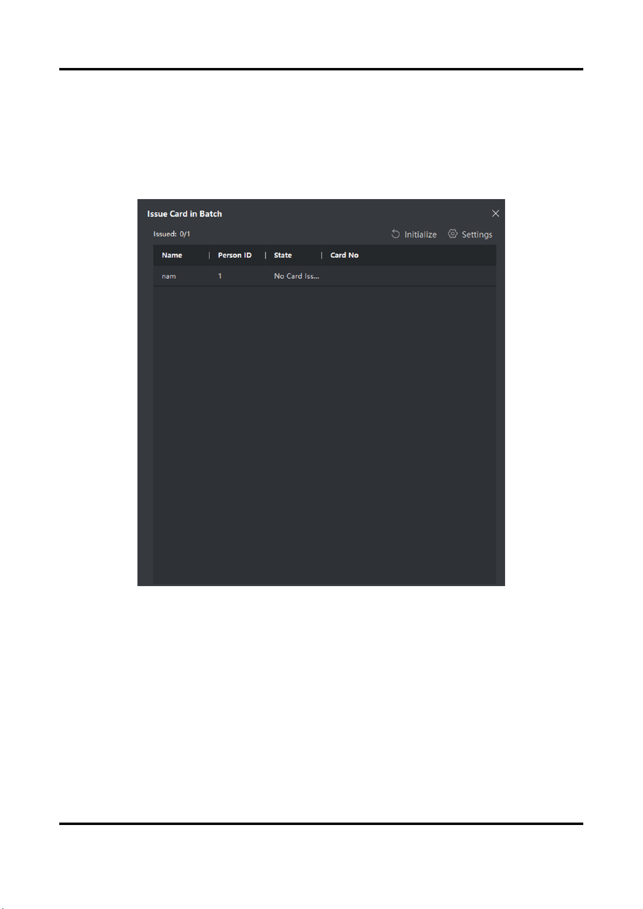
6.4.6 Issue Card in Batch
You can issue multiple cards for the person with no card issued in batch.
Steps
1. Click Batch Issue Cards to enter the dialog page. All the added person with no card issued will
display in the Person(s) with No Card Issued list.
Figure 6-2 Issue Card in Batch
2. Click Settings.
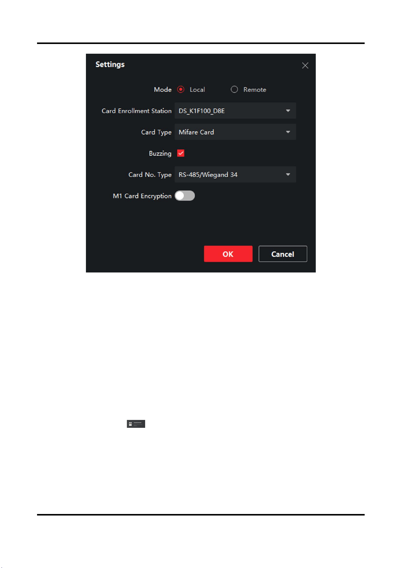
Video Intercom Villa Door Station User Manual
54
Figure 6-3 Card Settings
3. Select Card Type and Card No. Type.
4. Click OK to save the settings.
Result
After issuing the card to the person, the person and card information will display in the Person(s)
with Card Issued list.
6.4.7 Permission Settings
Add Permissions
Steps
1. On the main page, click AccessControlInfo → Access Group to enter the page.
2. Click +Add to pop up the adding dialog box.
3. Configure the parameters.
1) Enter the Name of the permission.
2) Select the Template of the schedule.
3) Check the person to Selected according to your needs.
4) Check the device to Selected according to your needs.
Video Intercom Villa Door Station User Manual
55
4. Click Save.
5. Check the permission and click Apply All to Device.
The status of the permission displays as Applied.
6. Optional: Click Applying Status to check the details.
Modify/Delete Permissions
On the page of the permission settings, click to edit the parameters of the permission.
Select one or more permissions, click Delete to remove the permissions.
6.5 Video Intercom Settings
The Video Intercom Management module provides the function of video intercom, checking call
logs and managing notice via the iVMS-4200 Client Software.
Note
For the user with access control module permissions, the user can enter the Access Control
module and manage video intercom and search information.
You should add the device to the software and configure the person to link the device in Access
Control module before your configuration remotely.
On the main page, click AccessControlInfo → Video Intercom → Video Intercom on the left
bar to enter the Video Intercom page.
6.5.1 Receive Call from Door Station
Steps
1. Select the client software in the page to start calling the client and an incoming call dialog will
pop up in the client software.
2. Click Answer to answer the call. Or click Hang Up to decline the call.
3. After you answer the call, you will enter the In Call page.
Adjust the Volume of
Loudspeaker
Click to adjust the volume of loudspeaker.
Hang Up
Click Hang Up to hang up.
Adjust the Volume of
Microphone
Click to adjust the volume of microphone.
Unlock Remotely
For door station, you can click to open the door remotely.
Video Intercom Villa Door Station User Manual
56
Note
●
One video intercom device can only connect with one client software.
●
The maximum ring duration can be set from 15s to 60s via the Remote Configuration of the
video intercom device.
●
The maximum speaking duration between indoor station and iVMS-4200 can be set from
120s to 600s via the Remote Configuration of indoor station.
●
The maximum speaking duration between door station and iVMS-4200 can be set from 90s to
120s via the Remote Configuration of door station.
6.5.2 Release Notice
You can create different types of notices and send them to the residents. Four notice types are
available, including Advertising, Property, Alarm and Notice Information.
Before You Start
Make sure the person has been added to the client.
Steps
1. On the video intercom settings page, click Notice to enter the page.
2. Click +Add to pop up the adding dialog box.
3. Select the person according to your needs.
4. Edit the Subject, Type and Information.
5. Click View to select the picture.
6. Click Send.
Note
●
Up to 63 characters are allowed in the Subject field.
●
Up to 6 pictures in the JPGE format can be added to one notice. And the maximum size of one
picture is 512KB.
●
Up to 1023 characters are allowed in the Information field.
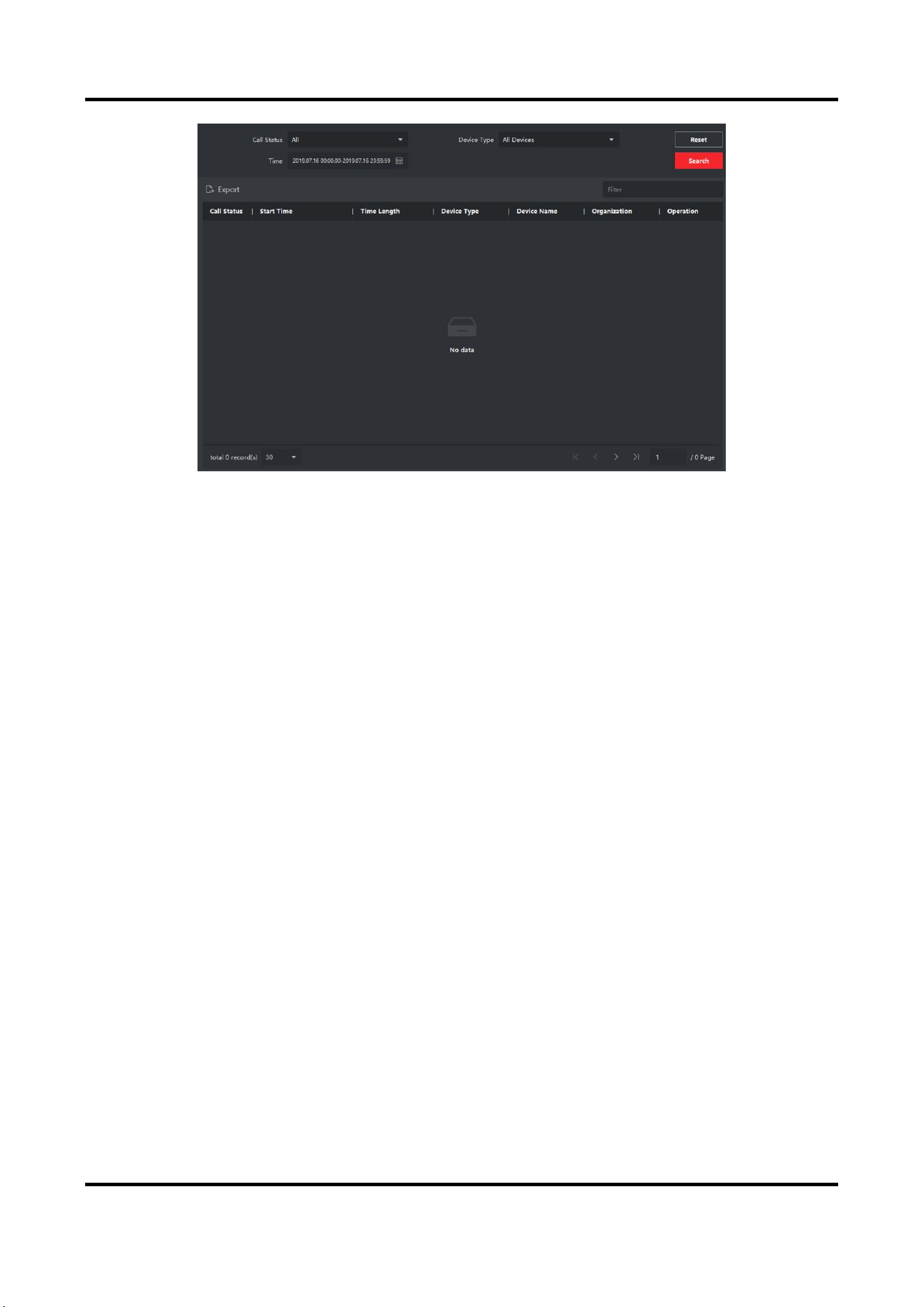
6.5.3 Search Video Intercom Information
Search Call Logs
Steps
1. On the Video Intercom page, click Call Log to enter the page.
Video Intercom Villa Door Station User Manual
57
Figure 6-4 Search Call Logs
2. Set the search conditions, including call status, device type, start time and end time.
Call Status
Click ˅ to unfold the drop-down list and select the call status as Dialed, Received or Missed.
Or select All to search logs with all statuses.
Device Type
Click ˅ to unfold the drop-down list and select the device type as Indoor Station, Door
Station, Outer Door Station or Analog Indoor Station. Or select All Devices to search logs
with all device types.
Start Time/End Time
Click the time icon to specify the start time and end time of a time period to search the logs.
Reset the Settings
Click Reset to reset all the configured search conditions.
3. Click Search and all the matched call logs will display on this page.
4. Optional: Check the detailed information of searched call logs, such as call status, ring/speaking
duration, device name, resident organization, etc.
5. Optional: Input keywords in the Search field to filter the desired log.
6. Optional: Click Export to export the call logs to your PC.
Search Notice
Steps
1. On the Video Intercom page, click Notice to enter the page.
2. Set the search conditions, including notice type, start time and end time.
Type
Video Intercom Villa Door Station User Manual
58
Select Advertising Information, Property Information, Alarm Information or Notice
Information as Type according to your needs.
Start Time/End Time
Click the time icon to specify the start time and end time of a time period to search the logs.
Reset the Settings
Click Reset to reset all the configured search conditiions.
3. Click Search and the matched notice will display on this page.
4. Optional: Click Export to export the notices to your PC.
6.5.4 Upload Armed Information
Steps
1. On the main page, click upper right → Tool → DeviceGuard to enter the page.
2. Enable to arm or disarm the device.
Note
●
While device has been added to the client software, the device armed by default.
●
When the device is armed, the alarm logs upload to the client software automatically.
●
Click Alarm Application → Event Search to search the alarm logs.
3. Optional: Click Arm All or Disarm All to arm or disarm all the device.
Video Intercom Villa Door Station User Manual
59
A. Communication Matrix and Device Command
Communication Matrix
Scan the following QR code to get the device communication matrix.
Note that the matrix contains all communication ports of Hikvision access control and video
intercom devices.
Figure A-1 QR Code of Communication Matrix
Device Command
Scan the following QR code to get the device common serial port commands.
Note that the command list contains all commonly used serial ports commands for all Hikvision
access control and video intercom devices.
Figure A-2 Device Command

UD20207B