Loading ...
Loading ...
Loading ...

5
NOTE: This procedure will not show proper lower
guard operation if the tool is not on its side.
3. Grasp the lower guard by the sides and push it all
the way back into the blade housing.
4. Release the lower guard.
• If the guard immediately springs back into place,
it is working correctly and you may continue with
use.
• If the guard does not immediate spring back into
place, clean the upper and lower guards to remove
all chips and debris. Then, check
the operation again by starting with step 1.
• If the guard still does not immediately spring back
into place, contact a MILWAUKEE service facility
for repairs.
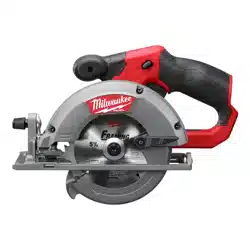
Installing and Removing Blades
1. Remove battery pack before installing or remov-
ing blades.
2. Place the saw on a at surface with the blade fac-
ing upwards. To remove the bolt from the spindle,
push in the spindle lock button. While holding in the
spindle lock button, use the wrench provided with
the tool to turn the bolt clockwise. Remove the bolt
and blade ange.
3. Slide the lower guard lever up to raise the lower
guard. Remove the blade from the spindle. Always
clean the spindle, upper guard and lower guard to
remove any dirt and sawdust.
NOTE: Do not remove inner blade ange. Larger
diameter of inner ange should face the blade.
Bolt
Outer ange
Inner ange
Spindle
4. To install a blade, place the blade on the spindle with
the teeth pointing in the same direction as the arrow
on the lower guard. Release the lower guard lever.
5.
Place the blade ange on the spindle and hand
tighten the bolt.
6. While holding in the spindle lock button, use the
wrench to turn the bolt counterclockwise and tighten.
Adjusting Depth
1. Remove battery pack.
2. To adjust the depth of
the cut, hold the saw
by the handle and
loosen the depth ad-
justing lever by
pushing it up to-
wards the motor
housing.
3. Raise or lower the
shoe to the desired position. Markings in 1/4" incre-
ments are located on the inner side of the upper
guard for depth setting. For the proper depth setting,
the blade should extend no more than 1/8" to 1/4"
below the material being cut.
1/4” 6mm
4. Press down on the depth adjusting lever to secure
the shoe position.
Adjusting Bevel Angle
1. Remove battery pack.
2. To adjust the angle of the cut, hold the saw by the
handle and loosen the bevel adjusting knob.
3. Hold the front of the shoe and rotate the saw by
the handle to the desired angle as indicated by the
markings on the bevel scale.
4. Tighten the bevel adjusting knob securely.
Adjusting the Blade to Shoe
The shoe has been adjusted at the factory to a 90° set-
ting. Inspect the saw regularly to make sure the blade
is 90° to the shoe.
1. Remove battery pack.
2. Set the bevel pointer to zero.
3. To make sure the blade is 90° to the shoe, place saw
on the blade side and retract lower guard. Place a
square against the blade and shoe to inspect the
degree setting.
Bevel
adjustment
screw
4. To adjust the degree setting, loosen the bevel ad-
justing knob. Turn the bevel adjustment screw in or
out until the blade is at a 90° angle with the shoe.
5. Tighten the bevel adjusting knob securely.
OPERATION
WARNING
To reduce the risk of injury, always
wear proper eye protection marked
to comply with ANSI Z87.1.
When working in dusty situations, wear appro-
priate respiratory protection or use an OSHA
compliant dust extraction solution.
Keep hands away from the blade and other mov-
ing parts.
Always remove battery pack before changing
or removing accessories. Only use accessories
specically recommended for this tool. Others
may be hazardous.
Kickback causes and related warnings
– Kickback is a sudden reaction to a pinched, bound
or misaligned saw blade, causing an uncontrolled
saw to lift up and out of the workpiece toward the
operator;
Loading ...
Loading ...
Loading ...