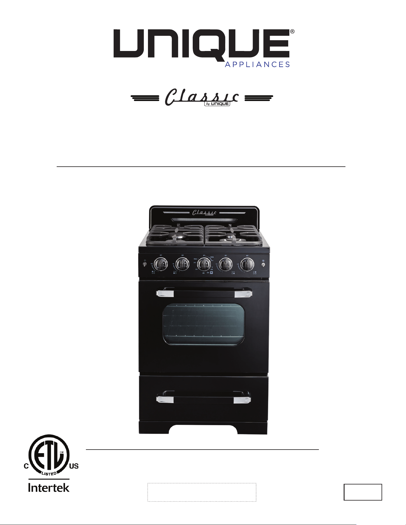
OWNER’S GUIDE
CLASSIC RETRO BY UNIQUE
24” CONVECTION GAS RANGE
serial number:
MODEL NUMBERS: UGP-24CR W, UGP-24CR B, UGP-24CR R,
UGP-24CR LB, UGP-24CR LG, UGP-24CR T
5010059
JAN23V3
CLASSIC RETRO BY UNIQUE 24” CONVECTION GAS RANGE
GAS RANGE - NG & LPG CONVERTIBLE
READ AND SAVE THESE INSTRUCTIONS
Have the dealer where you purchase your new range install it or have him recommend
a qualied installer. Installation must conform with local codes. In the absence of local
codes, the installation must conform with the National Fuel Gas Code, ANSI Z223.
1-Latest Edition in the U.S.A. or the CAN/CGA B149.1 or .2 Installation Codes in Canada.
Installation & Owner’s Manual
This manual contains information for:
Important Safeguards
Installation
Use and Care
Certain ranges come equipped with special features. Determine from a study of
your range which of the instructions given in this booklet pertain to your range.
This booklet gives valuable instructions covering the installation, adjustment
and use of your range.
How to Obtain Service and/or Parts
When your range does not operate in accordance with the instructions in the manual,
you should contact the dealer in your immediate vicinity for service. Or, the purchaser
may contact the service organization noted on the warranty.
Important
TO THE OWNER OF THE RANGE: Retain this owner’s manual for future reference.
TO THE INSTALLER: Leave this owner’s manual with the range.
Read and Save These Instructions
2245 Wyecroft Road #5
Oakville, Ontario, Canada L6L 5L7
Ph: 905-827-6154 Toll Free: 1-877-427-2266 Email: [email protected]
www.UniqueAppliances.com
MANUFACTURED & CERTIFIED BY
Unique Gas Products Ltd
X2

4
05 Important safety instructions
14 Energy saving ideas
15 Installation instructions
16 How to install the backsplash
17 Gas connections
20 Wall clearances
23 Gas range conversion
28 Adjustingthetopburnerandovename
29 Operation of range
35 Alignments and adjustments
36 Cleaning the range
38 Care and maintenance
43 Troubleshooting
45 Wiring diagram
46 Parts diagram - 24” Model
50 Appliance information
51 Warranty
52 Notes
52 Contact us
UNIQUE GAS RANGE
Table of Contents
5
BEFORE USING YOUR GAS RANGE
WARNING
HAVE THIS RANGE INSTALLED BY A QUALIFIED INSTALLER.
Improper installation, adjustment, alteration, services, or maintenance can cause injury or prop-
ertydamage.Consultaqualiedinstaller,serviceagency,orthegassupplier.
BEFORE USING YOUR GAS RANGE:
• Remove the exterior and interior packing.
• Removetheprotectivelmonsteelandaluminumparts.
• Check to be sure you have all of the parts listed below.
• 1 backsplash
• LP gas conversion packet (injectors for LP gas, 6pcs)
• 2 anti-tip brackets
• 2 pan supports
• 2 oven racks
• 4 caps and bases in the burner assembly
• 1 regulator (pre-installed)
• 2 screws for backsplash
• 1 instruction/installation manual
• Clean the interior surface with lukewarm water using a soft cloth
• Have the installer show you the location of the range’s gas shut-off valve and how to shut it
off if necessary.
• Haveyourrangeinstalledandproperlygroundedbyaqualiedinstallerinaccordancewith
the installation instructions.
• Donotattempttorepairorreplaceanypartofyourrangeunlessitisspecicallyrecommend-
ed in this manual.
• Besureyourrangeiscorrectlyadjustedbyaqualiedservicetechnicianorinstallerforthe
type of gas (natural or LP) that is being used.
• Donotremovepermanentlyafxedlabels,warnings,orplatesfromtheunit.Thismayvoid
the warranty.
• The installer should leave these instructions with the consumer who should retain for local
inspector’s use and for future reference.
• Please observe all local and national codes and ordinances.

6
Welcome & Congratulations
Congratulations on your purchase of a UNIQUE range! We are very proud of our product – and
are completely committed to providing you with the best service possible. Your satisfaction is
our #1 priority. Please read this manual very carefully. It contains valuable information on how to
properly maintain your new Unique gas range.
We know you will enjoy your new range and Thank You for choosing one of our Unique
Appliances! We hope you will consider us for future purchases.
IMPORTANT PRECAUTIONS AND RECOMMENDATIONS
This appliance is designed and manufactured solely for the cooking of domestic (household)
food and is not suitable for any non-domestic application and therefore CANNOT be used in a
commercial environment.
The appliance guarantee will be void if the appliance is used within a non-domestic environment
i.e. a semi commercial, commercial or communal environment..
PLEASE READ AND SAVE THESE INSTRUCTIONS
Thismanualprovidesspecicoperationinstructionsforyourmodel.Useyourrangeonlyas
instructed in this manual. These instructions are not meant to cover every possible condition
and situation that may occur. Common sense and caution must be practiced when installing,
operating and maintaining the appliance
Record in the space provided below the Model No. and Serial No. of this appliance.
These numbers are found on the serial plate located at the back of the range.
Model No. ________________________
Serial No. ________________________
Purchase Date________________________
Record these numbers for future use.
IMPORTANT:
Keep a copy of your bill of sale. The date on the bill establishes the warranty
period should service be required. If service is performed, it is in your best interest to obtain and
keep all receipts.
PLEASE DO THIS NOW!
Please visit our website at https://UniqueAppliances.com/product-registration/ to register your
product.
7
READ ALL IMPORTANT SAFEGUARDS AND
ALL INSTRUCTIONS BEFORE USING THE APPLIANCE.
IF YOU SMELL GAS:
• Open windows
• Don’t touch electrical switches
• Extinguishanyopename
• Immediately call your gas supplier
FOR YOUR SAFETY:
• Keepapplianceareaclearandfreefromcombustiblematerialsgasolineandotherammable
vapors and liquids.
WARNINGS
Destroy the carton and plastic bags after the range is unpacked. Children should not use
packaging material for play. Cartons covered with rugs, bedspreads, or plastic sheets can
become airtight chambers. Remove all staples from the carton. Staples can cause severe cuts
anddestroynishesiftheycomeincontactwithotherappliancesorfurniture.
Be safety conscious. The preparation of food in an oven requires temperatures that could
cause severe burns. Before using this new appliance, carefully read and follow all instructions.
The California Safe Drinking Water and Toxic Enforcement Act of 1986 (Proposition 65) requires
the Governor of California to publish a list of substances known to the State of California to
cause cancer or reproductive harm. In addition, businesses must warn customers of potential
exposure to such substances.
Users of this appliance are hereby warned that the burning of gas can result in low-level
exposure to some of the listed substances, including formaldehyde, benzene, soot and carbon
monoxide. This is caused primarily from the incomplete combustion of natural gas or LP fuel.
Properly adjusted burners will minimize incomplete combustion. Exposure to these substances
can also be minimized by properly venting the burners by opening a window or using a
ventilating hood or fan.
WARNING

8
Notice: Never keep pet birds in the kitchen. Birds have a very sensitive
respiratory system. Fumes released from cooking oil, fat, margarine or
overheated non-stick cookware may be harmful or fatal to birds.
PROPER INSTALLATION: Besureaqualiedtechnicianinaccordancewiththe
National Fuel Gas Code ANSI Z223.1/NFPA54 properly installs your appliance.
Install only per installation instructions provided in the literature package for this
range. Be sure leveling legs are in place at the bottom corners of the range. If
necessary, raise or lower the leveling legs at the base of the range by turning
clockwise or counter clockwise to insure a level range.
Askyourdealertorecommendaqualiedtechnicianandanauthorizedrepair
service. Have the technician familiarize you with the locations of the manual gas
shut off valve and gas meter in the event it is necessary to shut off gas supply to
the unit during an emergency.
The following situations may cause serious bodily harm, death or property
damage.
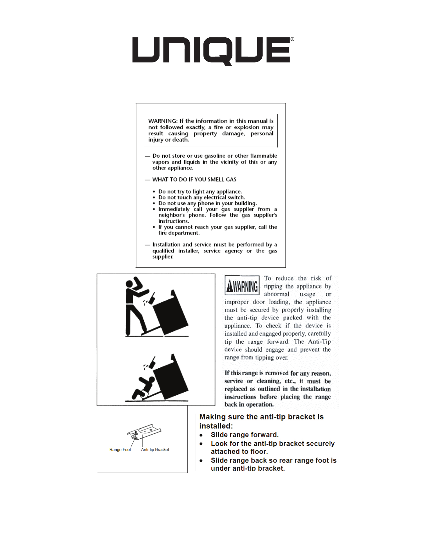
TO REDUCE THE RISK OF TIPPING OF THE RANGE, THE RANGE MUST
BE SECURED BY A PROPERLY INSTALLED ANTI-TIP BRACKET PROVIDED
WITH THE RANGE. TO CHECK IF THE DEVICE IS INSTALLED AND ENGAGED
PROPERLY, CAREFULLY TIP THE RANGE FORWARD. THE ANTI-TIP DEVICE
SHOULD ENGAGE AND PREVENT THE RANGE FROM TIPPING OVER.
REFER TO THE INSTALLATION INSTRUCTIONS PACKAGED WITH THE ANTI-
TIP BRACKET FOR PROPER ANTI-TIP BRACKET INSTALLATION.
• Never leave children alone or unattended in the area where an appliance is
in use. They should never be allowed to sit or stand on any part of the appliance.
Never leave the oven door open when the range is unattended.
• Do not store items of interest to children in the cabinets above a range or
on the backguard of a range. Children climbing on the range to reach the items
could be seriously injured.
Do not allow children to climb or play around the range. The weight of a child
on an open oven door may cause the range to tip, resulting in serious burns or
other injury.
IMPORTANT: Observeallgoverningcodesandordinances.Donotobstructowof
combustion and ventilation air.
9
USER SERVICING: Do not repair or replace any part of the appliance unless
specicallyrecommendedinthisowner’sguide.Onlyaqualiedtechnicianshould
do all other servicing. This will reduce the risk of personal injury and damage to the
range.
Storage in or on appliance: Flammable materials should not be stored in an
oven, near surface burners or in the broiler section. This includes paper, plastic
andclothitems,suchascookbooks,plasticwareandtowels,aswellasammable
liquids. Do not use the oven for storage. Do not store explosives, such as aerosol
cans, on or near the range.
Remove the oven door from any unused range if it is to be stored or discarded.
Stepping, leaning or sitting on the doors or broiler section of this range can
result in serious injuries and cause damage to the range.
The following situations could cause bodily injury or
property damage.
DO NOT TOUCH SURFACE BURNERS, AREAS NEAR THESE BURNERS,
OVEN BURNERS OR INTERIOR SURFACES OF THE OVEN. Both surface
burnersandovenburnersmaybehoteventhoughtheameisnotvisible.Areas
near surface burners may become hot enough to cause burns. During and after
use,donottouch,orletclothingorotherammablematerialstouchtheseareas
untiltheyhavehadsufcienttimetocool.Amongtheseareasaretherange,
surfaces facing the range, the oven vent openings and surfaces near these
openings, oven door and windows.
NEVER use this appliance as a space heater to heat or warm the room.
Doing so may result in carbon monoxide poisoning and overheating of the
oven.
Wear proper apparel. Loosettingorhanginggarmentsshouldneverbeworn
whileusingtheappliance.Donotletclothingorotherammablematerialscontact
surfaceburnersorinteriorsurfacesoftheovenuntiltheyhavehadsufcienttime
to cool.
Never modify or alter the construction of the range. Do not remove leveling
legs, panels, wire covers, anti-tip brackets or any other permanent part of the
product.
When heating fat or grease, watch it closely. Fatorgreasemaycatchreif
allowed to become too hot.
10
Do not use water or our on grease res. Smothertherewithapanlid,baking
soda or use a dry chemical or foam-type extinguisher.
Operation of the Surface Burners. When the burners are operated for the
rsttime,asmallamountofsmokemaybegeneratedduetotaperesidueor
manufacturing lubrication, this is not dangerous. Operate the burners for about
veminutestoridtheburnersofthismaterialbeforecooking.
Use only dry potholders. Wet or damp potholders on hot surfaces could result in
burns from steam. Do not let the potholder touch hot heating areas. Do not use a
towel or other bulky cloth instead of a potholder.
Use proper ame size. Adjustamesizesoitdoesnotextendbeyondthe
edge of the cookware. The use of undersized cookware will expose a portion of
theburnerameandmayresultinsevereburnsordirectcontactandignitionof
clothing.Also,properrelationshipofcookwaretoburnerwillimproveefciency.
NEVER cover any slots, holes or passages in the oven bottom or cover
an entire rack with materials such as aluminum foil. Doing so blocks air
owthroughtheovenandmaycausecarbonmonoxidepoisoning.Aluminumfoil
liningsmayalsotrapheat,causingarehazard.Refertothecleaningsectionof
this manual for more information on the use of aluminum foil.
Placement of oven racks: Always place an oven rack in the desired location while
the oven is cool. If a rack must be moved when the oven is hot, use potholders
and grasp the rack with both hands to reposition. Do not let potholders contact hot
oven walls. Remove all cookware from the rack before moving.
Do not heat unopened food containers. Build-up of pressure may cause the
container to burst and result in injury.
Keep the oven vent duct unobstructed. The oven vent is located along the
bottom of the back guard. Touching the surfaces in the vent area when the oven
is being operated may cause severe burns. Also, do not place plastic or heat-
sensitive items on or near the oven vents. These items could melt or ignite. The
rangerequiresfreshairforproperburnercombustion.Donotblocktheowofair
around the base or beneath the lower front panel of the range.
Use care when opening oven door: Stand to the side of the oven when
opening the oven door. Slowly open the door to allow hot air or steam to escape
before removing or replacing food.
Know which knob controls each burner. Place a pan of food on the burner
before turning it on, and turn the burner off before removing the pan. Always turn to
thefullpositionwhenignitingtopburners.Thenadjusttheamesizesoitdoesnot
extend beyond the edge of the cookware.

11
Cookware handles should be turned inward and not extend over adjacent
surface burners. Toreducetheriskofburns,ignitionofammablematerials,and
spillage due to unintentional contact with the cookware, the handle of a cookware
should be positioned so that it is turned inward, and does not extend over adjacent
surface burners.
Never leave the surface burners unattended. Boilovers may cause smoking,
greasyspill-oversmaycatchreorapanwhichhasboileddrymaymelt.
Do not place hands between the spring tension hinge and the oven door
frame when you are removing the oven door. Youcouldpinchyourngers.
Allow parts to cool to room temperature before touching or removing them
from the range. Whenasurfaceburnerisrstturnedoff,theburnerandgrateare
hot enough to cause burns.
Clean the range regularly to keep all parts free of fat or grease, which could
catch re. Pay particular attention to the area underneath each surface burner.
Exhaustfanventilatinghoodsandgreaseltersshouldbeclean.Donotallowfat
orgreasetoaccumulate.Greasydepositsinthefancouldcatchre.Refertothe
hood manufacturer’s instructions for cleaning.
Do not use a “cyclonic” range hood with this product. Some range hoods
circulate air by blowing downward toward the range top then drawing the air back
up into the hood. This creates a “cyclonic” air wash that is designed for electric
ranges only. A “cyclonic” hood may cause the burners of a gas range to operate
improperly.
Glazed cookware: Only certain types of glass, glass/ceramic, ceramic,
earthenware, or other glazed cookware are suitable for rangetop service without
breaking, due to the sudden change in temperature. Check the manufacturer’s
recommendations for rangetop use.
Do not place plastic salt and pepper shakers, spoon holders or plastic
wrappings on top of the range. These items could melt or ignite. Potholders,
towelsorwoodenspoonscouldcatchreifplacedtooclosetotheame.
Do not use a wok equipped with a metal ring that extends beyond the burner.
Because this ring traps heat, the burner and grate could be damaged. Also, the
burner may not work properly, creating a carbon monoxide level above current
health standards.
Do not clean the oven door gasket. The door gasket is essential for a good seal.
Care should be taken not to rub, damage or move the gasket.
12
Flexible Connectors: If the gas range/oven is connected to a gas supply with a
metalexibleconnector,movetherange/ovenwithCAUTIONforserviceorcleaning.
Flexible connectors are not intended for repeated bending. Do not allow
cleaners to make contact with exible connectors.
The connector and its ttings are designed for use only on the original in-
stallation and are not to be reused for another appliance or at another loca-
tion. Connectors must comply with ANSI Z21.24.
It’s good practice for each household to have an appropriate re extinguish-
er for use in the event of a house re.
NOTE: The instructions appearing in this owner’s guide are not meant to cover
every possible condition and situation that may occur. Common sense and caution
must be practiced when operating and maintaining any appliance.
On sealed burner models never attempt to operate the surface burners with-
outthecooktop,burnercapsandignitionwiresrmlyinplace.Thereisariskofre
and/or explosion which could result in personal injury or property loss.
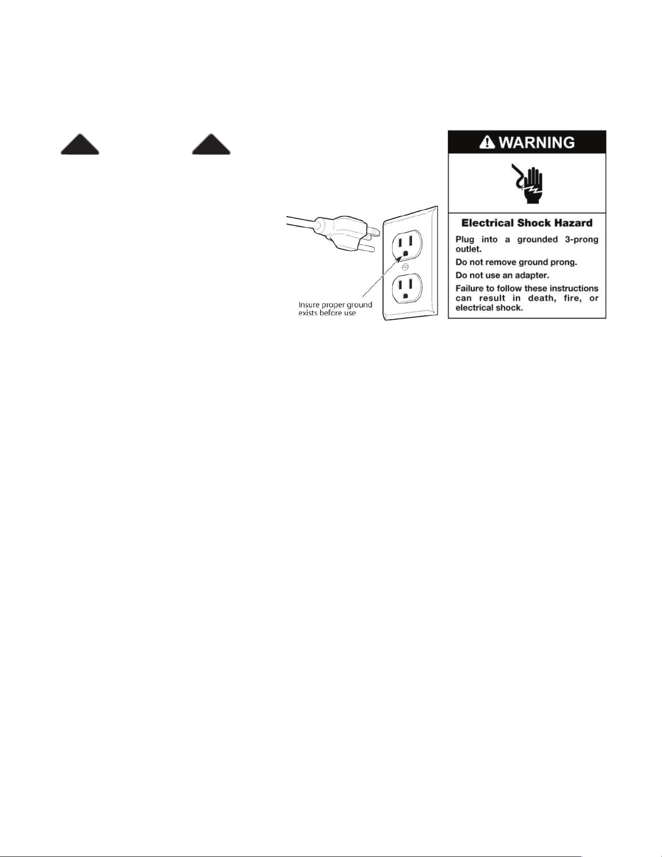
ELECTRICAL GROUNDING INSTRUCTIONS
FOR PERSONAL SAFETY, THIS APPLIANCE MUST BE PROPERLY GROUNDED.
This appliance is equipped with a three-prong grounding plug for your protection
against shock hazard and should be plugged directly into a properly grounded
socket. Do not cut or remove the grounding prong from the plug.
• The gas range must be installed with all electrical connections in accordance with
state and local codes. A standard electrical supply (115 V AC only, 60 Hz), prop-
erly grounded in accordance with the National Electrical Code and local codes
and ordinances is required.
Do not under any circumstances cut or remove the third (ground) prong from the
power plug. Electrical installation should comply with national and local codes.
REPLACEMENT PARTS
Only authorized replacement parts may be used in performing service on the
range. Replacement parts are available from factory authorized parts distributors.
Contact the nearest Unique parts distributor in your area.

13
CARBON MONOXIDE WARNING:
Carbon Monoxide is a possible danger when using any gas powered appli-
ance.
All gas appliances MUST be installed by a licensed professional who is famil-
iar with the Carbon Monoxide levels appropriate for each appliance.
The American Gas Association publishes CO emissions for appliances and
heating equipment through the ANSI Std. Z21.1
The EPA reports that a maximum CO (Carbon Monoxide) level of 9 PPM over
a 24 hour period is the residential interior ambient level standard.
( A properly ventilated home will have a normal CO level of less than 5 PPM.)
NON-VENTED GAS COOKING APPLIANCES:
Non-vented gas cooking appliances in a residential application are normally
used for a short period of time. The CO generated during the operation will
disperse to the air in the home and be purged to the outside through the nor-
mal air exchange.

14
Surface Cooking
Use lids when surface cooking. A lid traps steam and uses it to speed up the
cooking process. If you have a pressure cooker or vegetable steamer, use it. You’ll
waste fewer vitamins, save time and cut energy costs.
Usemedium-weight,atbottomedpansthatmatchtheamesize.Choosepans
made of metals that conduct heat well.
When cooking on a surface burner, use as little water as possible to reduce
cooking time.
Oven Cooking
Preheat the oven only when a recipe tells you. Put roasts and casseroles into a
cold oven; then turn on the oven.
Opening the oven door often to check on foods wastes energy.
Use the oven to prepare complete meals. For instance, start a roast, add
vegetables when the meat is half-cooked, and then warm rolls or dessert after the
main dishes are cooked.
Thaw frozen foods before cooking. Thawed food requires less cooking energy than
frozen food.
Make it a habit to turn the oven off before removing the cooked food.
ENERGY-SAVING IDEAS
15
Be sure appliance is properly installed and grounded by a quali ed technician.
It is the responsibility of the technician to make certain that your range is properly
installed. Situations caused by improper installation are not covered under the
warranty. Any expenses incurred due to such situations will not be paid by the
manufacturer of the appliance.
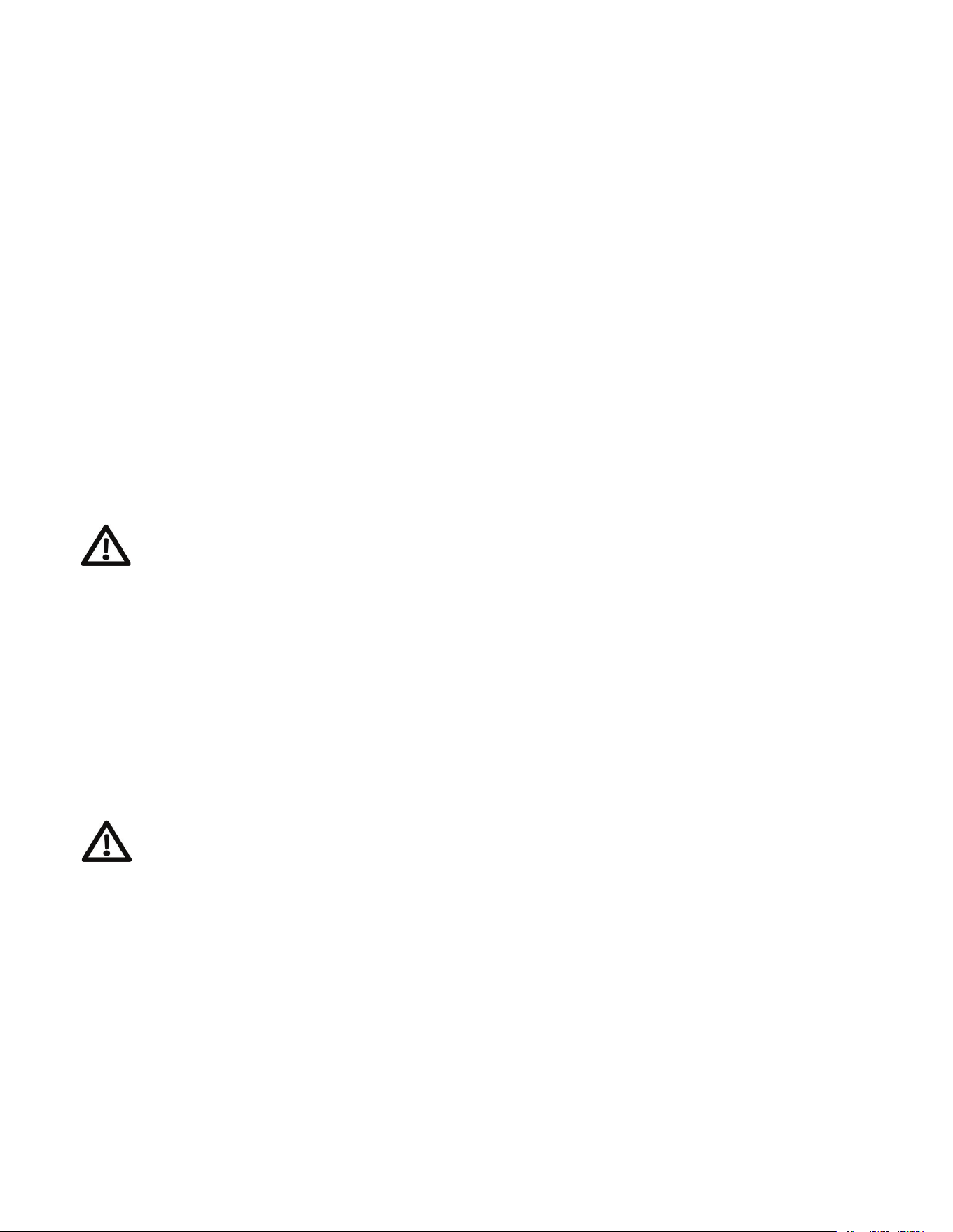
A child or adult can tip the range and be killed.
Install the anti-tip device to the structure and/or the
range. Verify the anti-tip device has been properly
installed and engaged. Engage the range to the
anti-tip device by ensuring the anti-tip device is re-
engaged when the range is moved. Re-engage the
anti-tip device if the range is moved. Do not operate
the range without the anti-tip device in place and
engaged. See installation instructions for details.
Failure to do so can result in death or serious burns
to children or adults.
If this range is removed for any reason, (eg. service
or cleaning), it must be replaced as outlined before
placing the range back in operation.
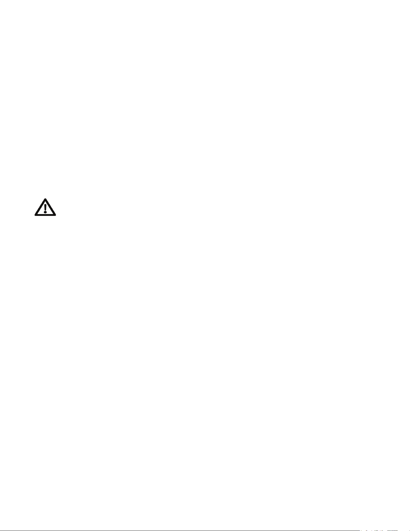
Levelling a Free-Standing Range
All free-standing ranges must be level to obtain
proper cooking results. The leveling legs should
be screwed into the corner brackets. Place pan or
measuringcuppartiallylledwithwateroralevel
on the oven rack. Adjust the leveling legs until the
range is level. The top of the side panels should be
level with the counter top.
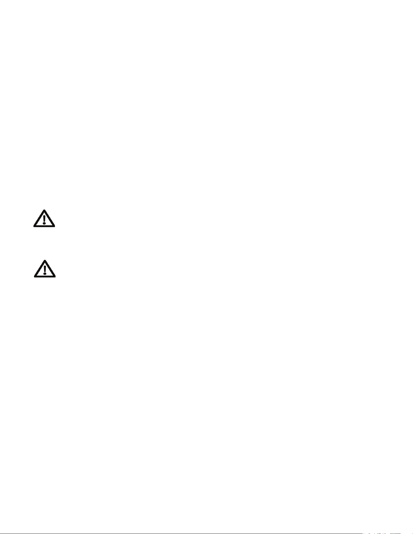
Making sure the anti-tip brackets are installed:
• Slide range forward.
• Look for the anti-tip bracket securely attached to
oor.
• Slide range back so rear range foot is under anti-
tip bracket.
INSTALLATION INSTRUCTIONS
16
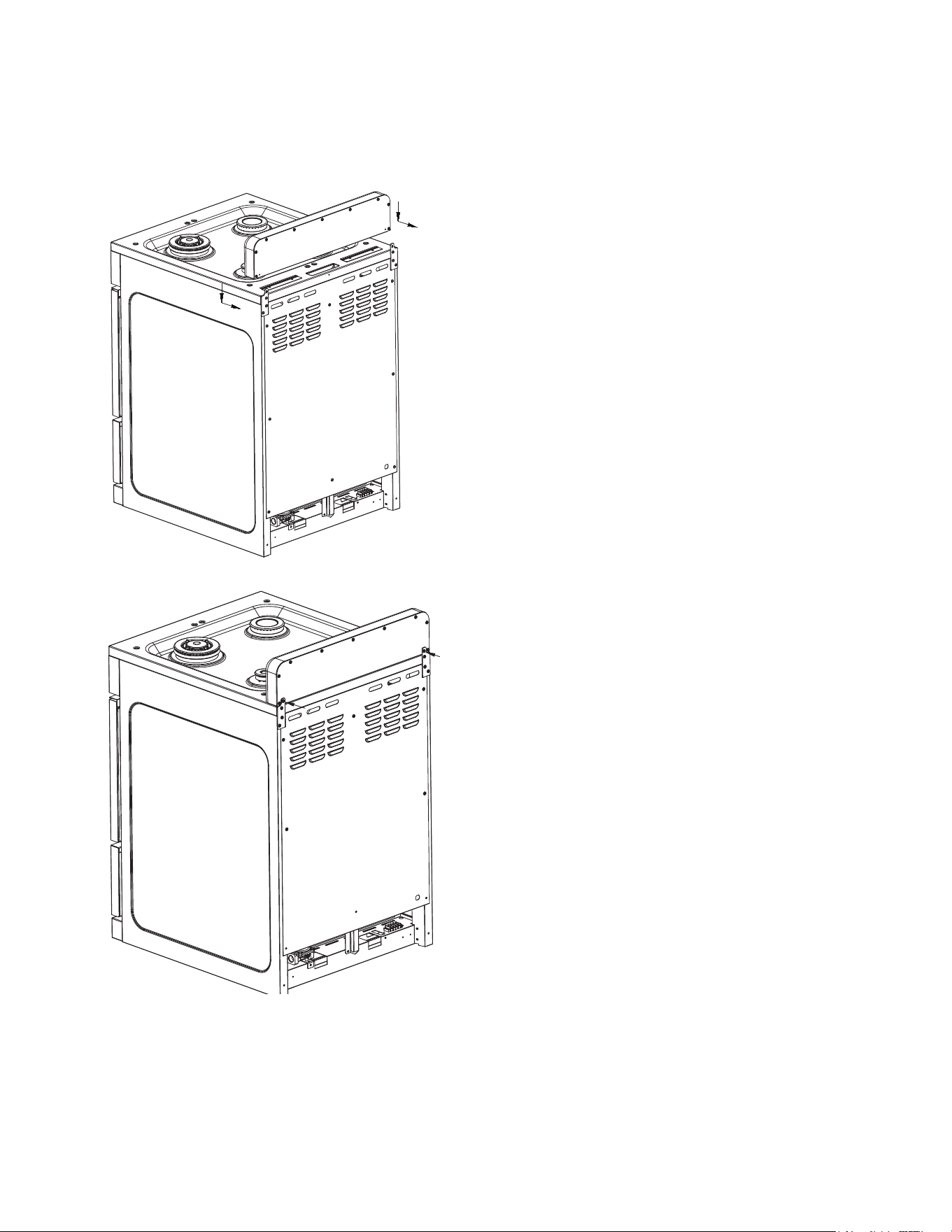
1. Align the backsplash to the rear
part of the cooktop as shown in
the diagram.
2. Secure the backsplash to the
cooktop from the back using the 2
Phillips head screws provided as
shown in the diagram.
HOW TO INSTALL THE BACKSPLASH
17
NOTICE TO MASSACHUSETTS APPLIANCE DEALERS:
Be sure this document is included in all gas range appliances sold to consumers in
the State of Massachusetts.
NOTICE: Massachusetts law requires the following:
• Appliancesmustbeinstalledbyalicensedplumberorgastter.
• Appliancesmustbeconnectedwithathree(3)foot(36”maximumlength)exible
gas connector and
• A “T” handle type manual gas valve in the gas supply line to the appliance.
Have the dealer where you purchase your new range install it or have him rec-
ommendaqualiedinstaller.Installationmustconformwithlocalcodes.Inthe
absence of local codes, the installation must conform with the National Fuel Gas
Code, ANSI Z223.1-Latest Edition in the U.S.A. or the CAN/CGA B149.1 or .2 In-
stallation Codes in Canada.
The range should be connected to the supply line with
1
/
2
inch black iron pipe or
acertiedexibletyperangeconnector.Topreventgasleaks,putanapproved
sealingcompound,whichisresistanttoliqueedpetroleumgases,onallthreaded
connections.
Important: Do not apply pressure directly to the range manifold pipe when tighten-
ing supply connections. The manifold pipe should be held securely at the pressure
regulator to prevent twisting. Hold the pressure regulator with a wrench during the
tightening of the connection, or the manifold pipe may be twisted and split, and
cause a dangerous leak.
The installation of ranges designed for manufactured (mobile) home installation
must conform with the Manufactured Construction and Safety, Title 24 CFR, Part
3280, [formerly the Federal standard for Mobile Home Construction and Safety,
Title 24, HUD (Part 280)] in the U.S.A. or C.S.A. Standard CAN/CGA Z240.4.2 in
Canada or, when such standards are not applicable with local codes.
The installation of ranges designed for recreational vehicle installation must con-
form to state or other codes and in the absence of such codes with the standard
for recreational vehicles ANSI A119.2.2–1982 in the U.S.A. or CAN/CGA Z240.4.2
in Canada. The installation of appliances designed for recreational park trailers
must conform to recreational park trailers, ANSI A119.5.
Note: Checkallpipingconnectionsintheunitforleaks.Neveruseanopename
to check for gas leaks. Use a soap solution with a recommended ratio of 75%
water and 25% dish washing soap. It’s possible for connections made at the fac-
tory to leak, due to vibration encountered in transportation. Make certain you have
checked them all, and repair any connections that leak.
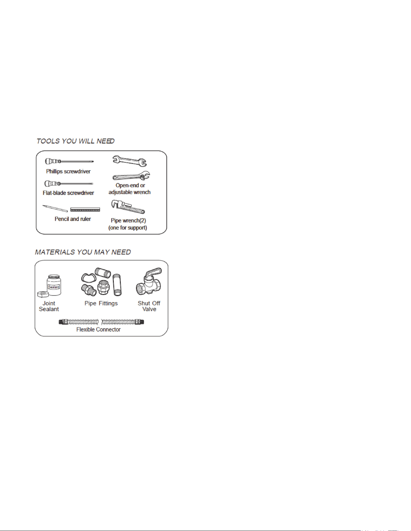
GAS CONNECTIONS (All Units)
18
The appliance and its individual shut-off valve must be disconnected from the gas
supply piping system during any pressure testing of that system at test pressures
in excess of
1
/
2
psig.
The appliance must be isolated from the gas supply piping system by closing its
individual manual shut-off valve during any pressure testing of the gas supply
piping system at test pressures equal to or less than
1
/
2
psig.
• Gas line shut-off valve
• To reduce the possibility of gas leaks, apply
Teontapeorathreadcompoundapproved
for use with LP or Natural gases to all threaded
connections.
• Useaexibleapplianceconnectortoconnect
your gas supply to the appliance. A 3 foot length
is recommended for ease of installation but
other lengths are acceptable. Never use an old
connector when installing a new range.
• Check for leaks using a leak detector or soapy
water with a recommended ratio of 75% water,
25% dish washing soap.
Installation
It is the responsibility of the installer to make
certain that the range is properly adjusted at
the time of installation. Situations caused by
improper adjustments or improper installation
are not covered under the warranty. Any expenses incurred due to such situations
will not be paid by the manufacturer of the appliance.
Connecting gas to range
This range is designed to operate at a pressure of 4” of water column on natural
gas (NG) or 10” of water column on propane gas (LPG).
Make sure you are supplying your range with the type of gas for which it is
designed. This range comes equipped from the factory equipped for use
with NG (natural gas). This range is convertible for use on propane (LPG) also
(propaneoricesincludedinthepackaging).
GAS CONNECTIONS (continued)

19
WhenusingthisonLPGgas,conversionmustbemadebyaqualiedLPG
installer before attempting to operate the range on that gas.
For correct operation, the pressure of natural gas supplied to the regulator should
be between 4” and 5” of water column. For LP gas, the pressure supplied must be
between 10” and 12” of water column.
When checking for correct operation of the regulator, the inlet pressure must be at
least 1” more than the operating -manifold- pressure as given above. The pressure
regulator located at the back of the range manifold must remain in the supply line
regardless of whether natural or LP gas is being used.
Regulator is only good for psi (14” w.c.) so test pressure must not exceed
1
/
2
” psi.
Shut off the main gas supply valve before removing the old range and leave it off
until the new hook-up has been completed.
Because hard piping restricts movement of the range, the use of a CSA/ETL
certiedexiblemetalapplianceconnectorisrecommendedunlesslocalcodes
require a hardpiped connection. Never reuse an old connector when installing a
new range. If the hard piping method is used, you must carefully align the pipe; the
range cannot be moved after the connection is made.
To prevent gas leaks, use pipe joint compound resistant to LP or NG gases
(depending on set up) on all male -external- pipe threads.
1. In an easily accessible location, install a service manual gas shut off valve. Be
sure everyone operating the range knows where and how to shut off the gas
supply to the range.
2. When all connections have been made, be sure all range controls are in the off
position and turn on the main gas supply valve. Check for gas leaks by using
a soap and water solution. If a gas leak is present, shut off gas immediately,
tighten all connections, and retest for leaks.
3. Anyopeninginthewallbehindtheapplianceandintheoorunderthe
appliance must be sealed.
After installation:
1. Check ignition of cooktop burners.
2. Check ignition of oven burner.
3. Check ignition of broiler burner.
4. Checkforgasleaksatallgasconnections(usingagasdetector,neveraame)
GAS CONNECTIONS (All Units)
20
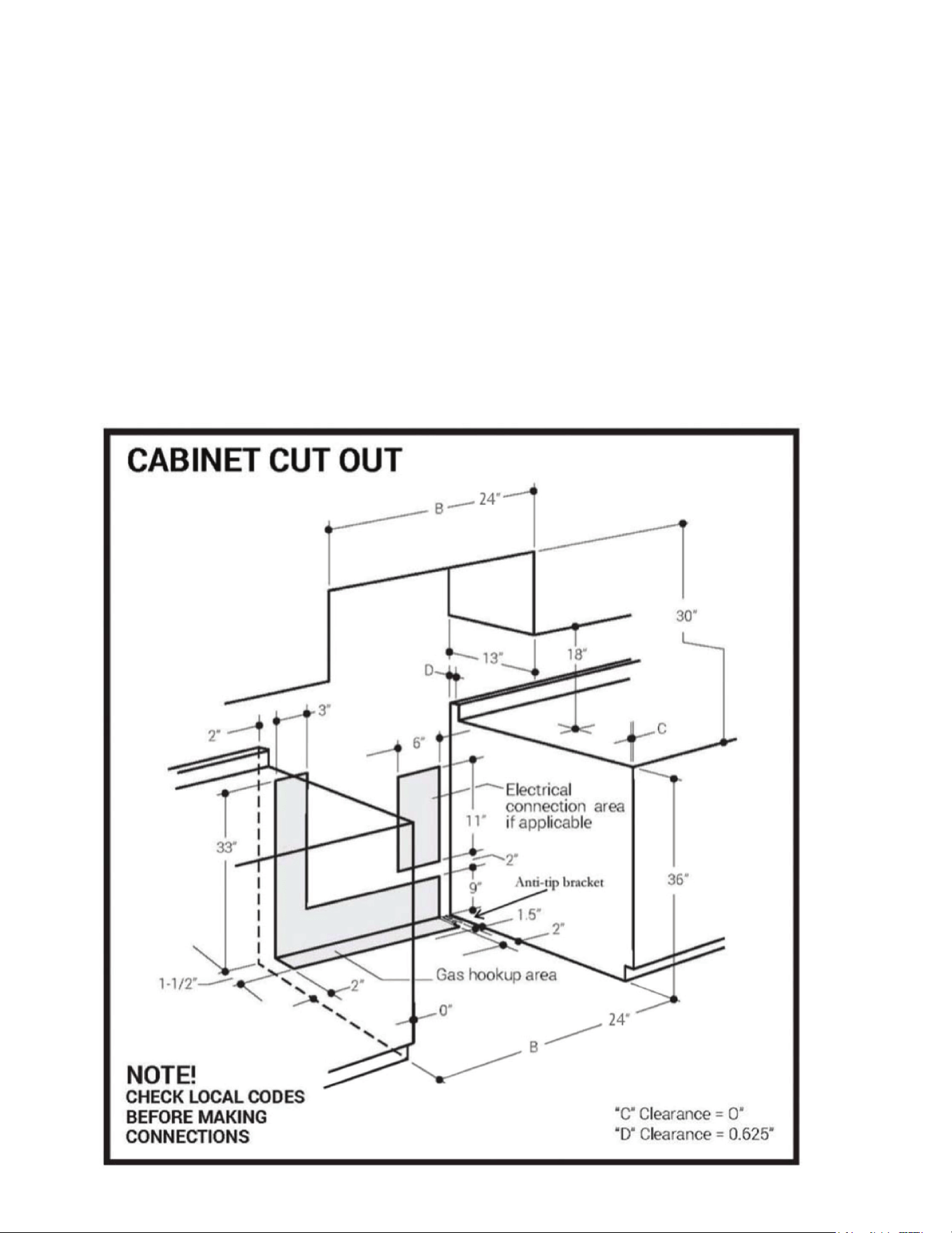
All units must be installed in accordance to minimum rear and side wall clearance
and clearances extended vertically above cooking top which are stated on the
serial plate located at the back of the range.
ANY OPENINGS IN THE WALL BEHIND THE UNIT AND IN THE FLOOR UNDER
THE UNIT MUST BE SEALED.
Note. Due to potential hazards it is recommended that storage cabinets NOT be
installed above the cooking surface.
IN THE EVENT OVERHEAD CABINETS ARE INSTALLED, THE MAXIMUM
DEPTH OF CABINETS INSTALLED ABOVE COOKING TOPS SHOULD BE 13”.
WALL CLEARANCES
24”
21
WALL CLEARANCES (continued)
22
To convert application and/or adjust from NG to LPG
The range is set for use with Natural Gas (NG). The factory setting is indicated on
the serial plate. When set for Natural Gas operation, the pressure regulator will
regulate the gas to 4 inches water column pressure. When set for Liquid Propane
Gas (LPG) operation, the pressure regulator will regulate the pressure to 10 inches
water column.
Natural Gas to Liquid Propane Gas Conversion
Theconversionkitmustbeinstalledbyqualiedserviceagency.
WARNING: Please ensure before beginning converting the appliance that the gas
supply is shut off and the electrical connection is disconnected. Failure to do can
result in injury or property damage.
GAS RANGE CONVERSION
“Thisconversionkitshallbeinstalledbyaqualiedserviceagencyin
accordance with the manufacturer’s instructions and all applicable codes and require-
ments of the authority having jurisdiction. If the information in these instructions is not
followedexactly,are,explosionorproductionofcarbonmonoxidemayresultinprop-
ertydamage,personalinjuryorlossoflife.Thequaliedserviceagencyisresponsible
for the proper installation of this kit. The installation is not proper and complete until the
operationoftheconvertedappliancesischeckedasspeciedinthemanufacturer’s
instructions supplied with the kit.”
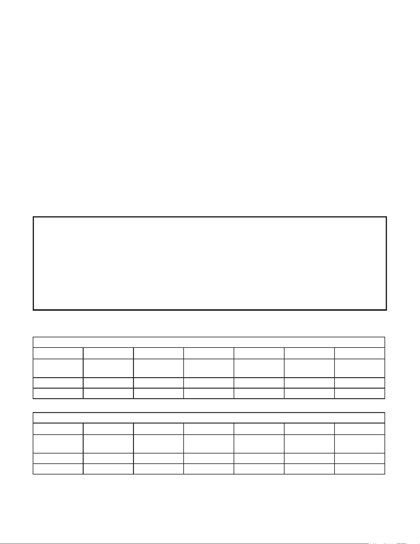
Natural Gas Orifices
BTU 11,000 10,000 3,200 10,000 8,000 12,800
BURNER Auxiliary
Burner
Semi-Rapid
Burner
Triple Burner Rapid Burner Broil Burner Oven Burner
POSITION Front Right Rear Left Rear Right Front Left
ORIFICE 1.62 1.50 0.90 1.50 1.41 1.85
Liquid Propane Gas Orifices
BTU 10,500 9,000 3,200 9,000 9,000 12,800
BURNER Auxiliary
Burner
Semi-Rapid
Burner
Triple Burner Rapid Burner Broil Burner Oven Burner
POSITION Front Right Rear Left Rear Right Front Left
ORIFICE 1.00 0.93 0.57 0.93 0.93 1.07
24” Model
23
24” MODEL
GAS RANGE CONVERSION
ATTENTION: YOUR PRODUCT IS PRE-INSTALLED WITH NATURAL GAS
INJECTORS AND REGULATOR.
IF YOU ARE USING LP GAS, PLEASE REFER TO THE INSTALLATION
INSTRUCTIONS INCLUDED WITH THE CONVERSION KIT.
Convertible Pressure Regulator
TherangeisshippedtooperateonNG.LPGorices
foradjustingtheminimumameareshippedwiththe
unit in a separate envelope with the manual. The inlet
pressure of the gas supply shall be in accordance with
the nominal inlet pressure of the regulator used on the
range or
1
/
2
psig maximum. The range should be tested
by pressurizing the regulator with an inlet pressure at
least 1 inch water column above the manufacturer’s
speciedmanifoldpressureshownontheserialplate.
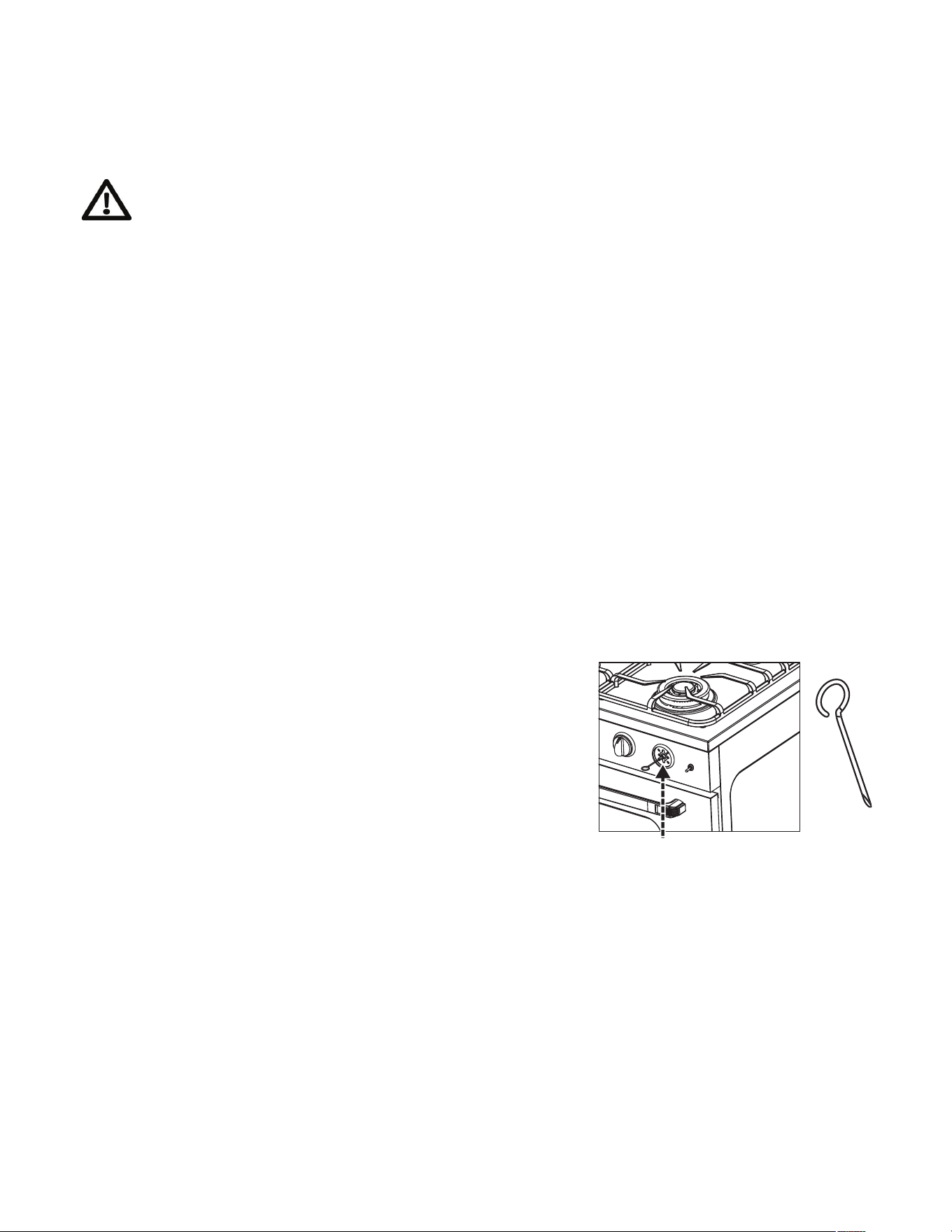
1. Orices
Parts List:
1. CAUTION: Before proceeding with
the conversion, shut off the gas
supply to the appliance prior to
disconnecting the electrical power
2. Locate convertible regulator at the
back of the range, left side facing
back of appliance. Unscrew cap to
locate pin.
3. On the side of the pin you will see the respective marking for LPG and NG.
4. UnscrewpinandipittotheLPGposition(arrowfacingcapindicating
correct setting)
5. Replace the cap back on the regulator
Top Burner Orices
6. Remove the grates, burners and
burner caps from the range to
accesstheorices.
24
7. Usea7mmwrenchtoremovetheorices.Eachoricecanbeaccessedeasily
- thelargerburneroriceislocatedontheburnerwall.
8. RemoveallNGorices,placeinthebagandstoreinasafeplace.
9. TaketheLPGoricesprovidedandinstallthemasshownbelow.
See below for rating of orice for each model
24” Model
Smallest Medium x 2 Largest Oven Broil
LPG 0.57 mm 0.93 mm 1.00 mm 1.07 mm 0.93 mm
10. Oncealltheoricesareinstalled,replaceallburnersandburnercaps,then
reuptheburnerstochecktheminimumameheight.
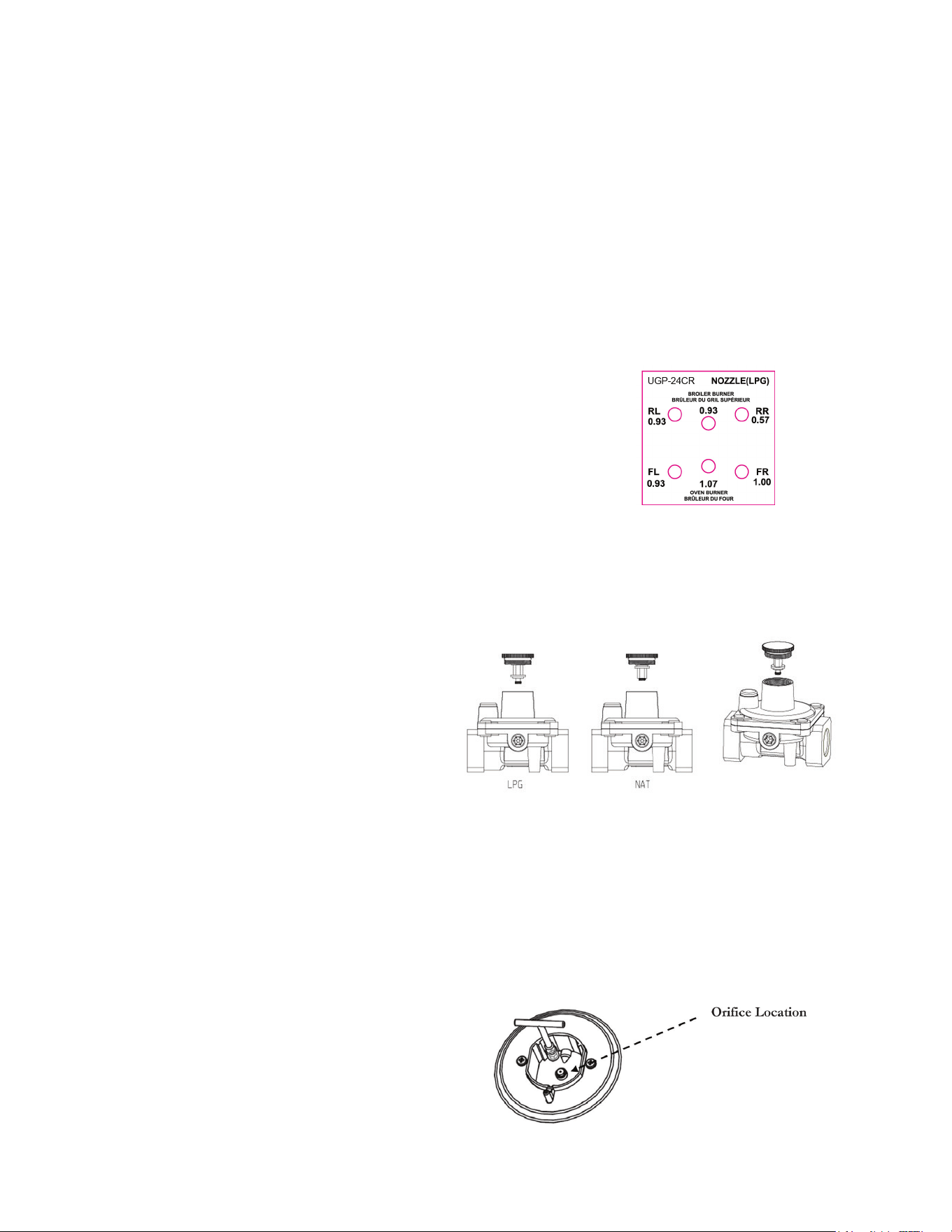
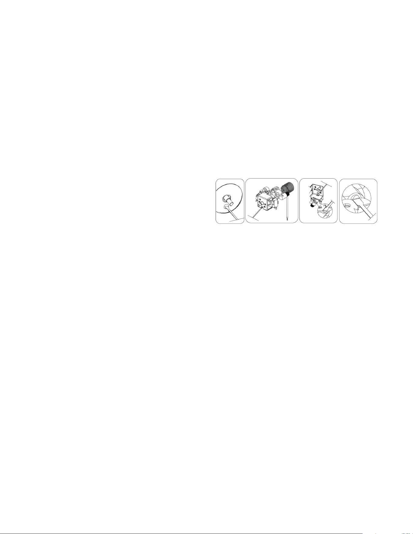
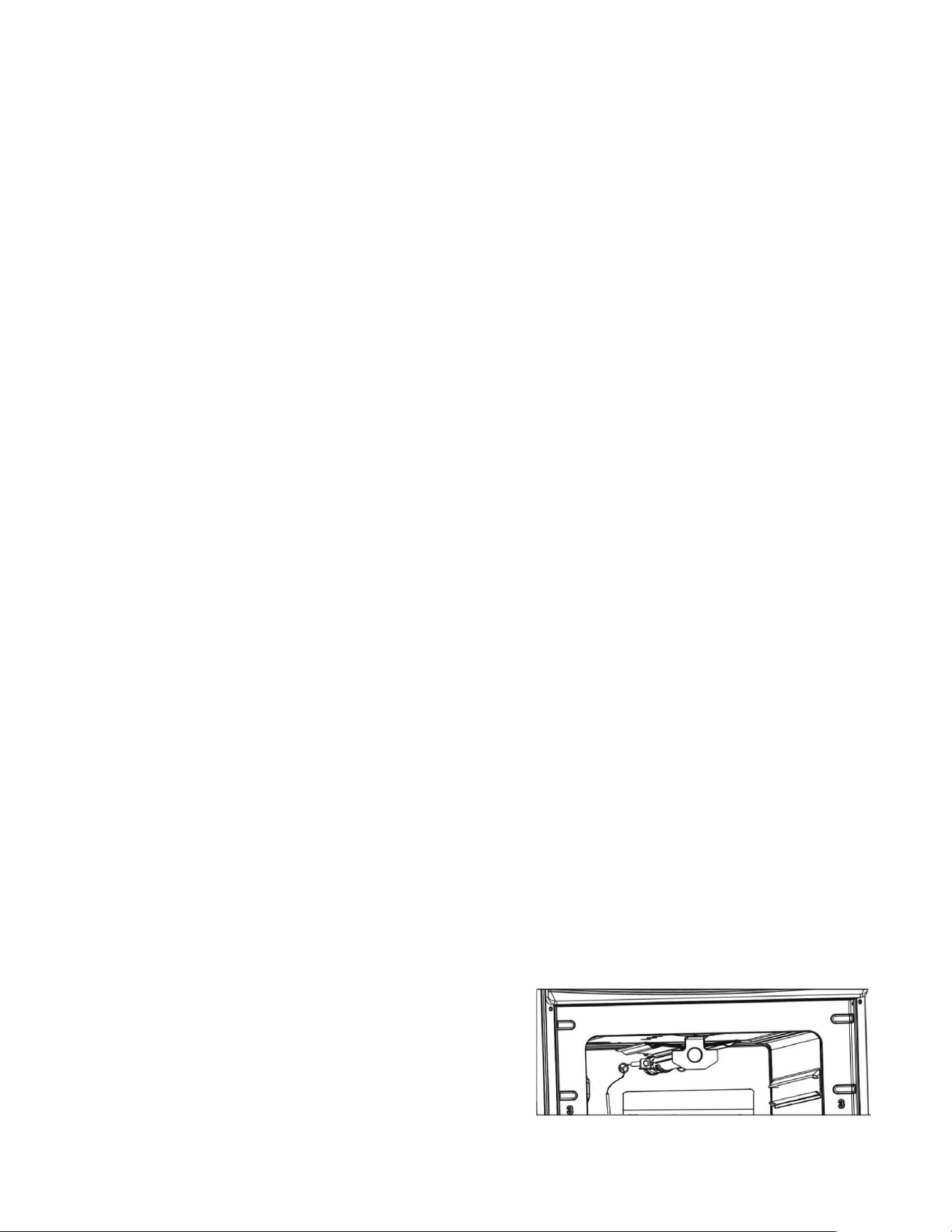
To replace the oven burner orice
1. Open oven door.
2. Remove all racks, then the bottom pan by lifting up
thebackrsttoreleasethefrontthenpullpanout.
3. Locate the burner tube and locate the retaining
screw at the front of the tube. Once this screw has
been removed, lift up the burner and pull away
slightlytoexposetheovenorice.
4. Witha7mmwrenchremovetheoriceandreplacewithLPGorices.
5. Replacetheburnertube,thenstartuptheoventocheckovename,making
sure it’s tight and blue. Adjust the air shutter at the back of the burner tube to
achieve this. Once you have the bottom pan and oven door closed, you will be
abletoseehowtheameshouldlookbyviewingtheamethroughthedoor.
To replace the broiler burner orice
1. Open oven door.
2. Locate the burner tube on the top of the oven cavity and locate the retaining
screw at the front of the tube. Once this screw has been removed, lift up the
burner and pull away slightlytoexposethebroilerorice.
3. Witha7mmwrenchremovetheoriceandreplacewithLPGorices.
4. Replacetheburnertube,thenstartupthebroilertocheckovename,making
sure it’s tight and blue. Adjust the air shutter at the back of the burner tube to
achieve this.
GAS RANGE CONVERSION (continued)
Orifice
Wrench
25
CHECKING FOR MANIFOLD GAS PRESSURE
To check the manifold gas pressure, remove the burner cap and connect a
manometer(watergauge)orotherpressuretestdevicetotheburnerorice.Usea
rubber hose with inside diameter of approximately ¼” hold the end of the hose tight
overtheorice.Turnthegasvalveon.Foramoreaccuratepressurecheck,haveat
least two (2) other top burners burning. Be sure that the gas supply (inlet) pressure
isatleastoneinchabovethespeciedmanifoldpressure.Maximumgassupply
pressure must not exceed 14” inch water column, minimum gas supply pressure
must be 1” inch water column above recommended pressure, 12” for propane gas,
and 5” water column for natural gas. When properly adjusted the manifold water
column pressure is 11” for LP/propane gas or 5” for natural gas.
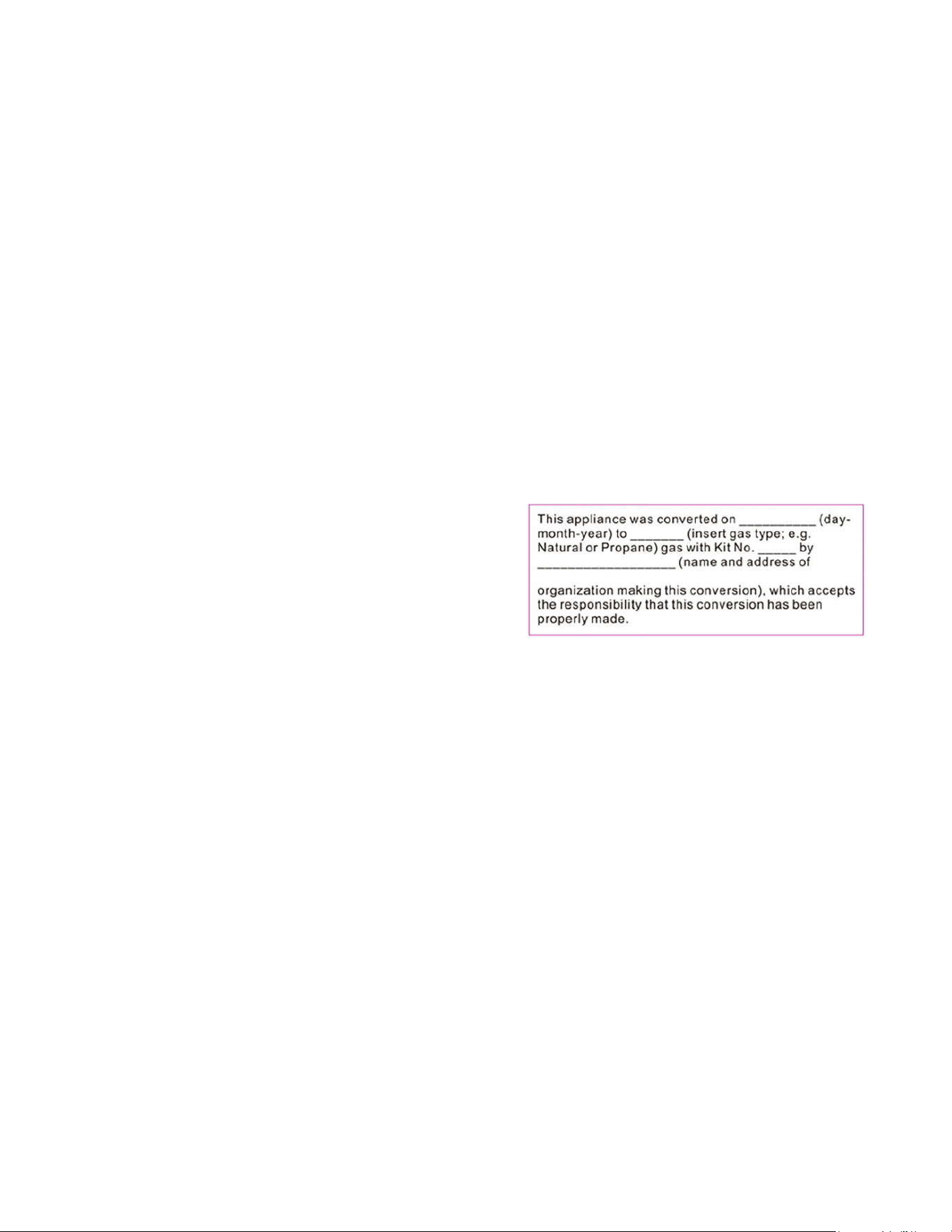
Note:Oncetheunithasbeenconvertedllouttheincludedstickerandplaceiton
the back of the range
Once you have completed the conversion,
check the operations of ignition making sure
eachofthe4burners,pilotameandoven
burneramearefunctioningcorrectly.Please
refer to pages 30 thrgugh 35 – Operation of
Range.
High Altitude Applications above 2000 feet:
At elevations above 2,000 feet, the range must be derated 4% for each 1,000 foot
above sea level. It is the installer’s responsibility to see that the range’s input rate is
adjusted properly.
GAS RANGE CONVERSION (continued)
25
26
ADJUSTING THE TOP BURNER AND OVEN FLAME
Keep appliance area clear and free from combustible materials,
gasoline, and other ammable vapors and liquids. Do not obstruct the
ow of air that is necessary for combustion and ventilation.
Top Burner Valves
Thetopburnershaveoricesthatarededicatedtothetypeoffueltobeused.
Theseoricesarenotadjustable.Theymustbechangedcompletelytoconvert
from one gas to the other. DO NOT DISCARD THE UNUSED ORIFICES. They
should be saved in order to convert the range back to its original fuel.
Whenconvertingthegasvalves,theminimumameadjustmentscrewmustbe
adjusted.
Pleaseseethesuppliedscrewdriverintheconversionkitalongwiththeorices.
Theproperamesizeisapproximately¼”obtained.–seeadjustmentprocedure
below.
Theproperlyadjustedmaximumameisapproximately¾”highandhasthree
distinct cones; the kindling point, the dark blue center cone, and the outer mantel.
ADJUSTING THE TOP BURNER FLAME
1. Ensure the range has gas supply and power
2. Light the burner
3. Set the top burner valve to the minimum position
4. Remove the knob by pulling straight out
5. Turn the valve fully counter clockwise.
Then proceed to adjust the adjustment screw
clockwiseforasmallerflameand
counter clockwiseforalargerflame.Adjustment:
Minimumflameshouldbeapprox:¼”tall.
OrificeLocationAdjustmentlocationisinsidethevalvestem.
6. Replace the knob
7. Repeat for each of the other burners
26
FLAME HEIGHT ADJUSTMENT
Adjustment location is inside
the valve stem
27
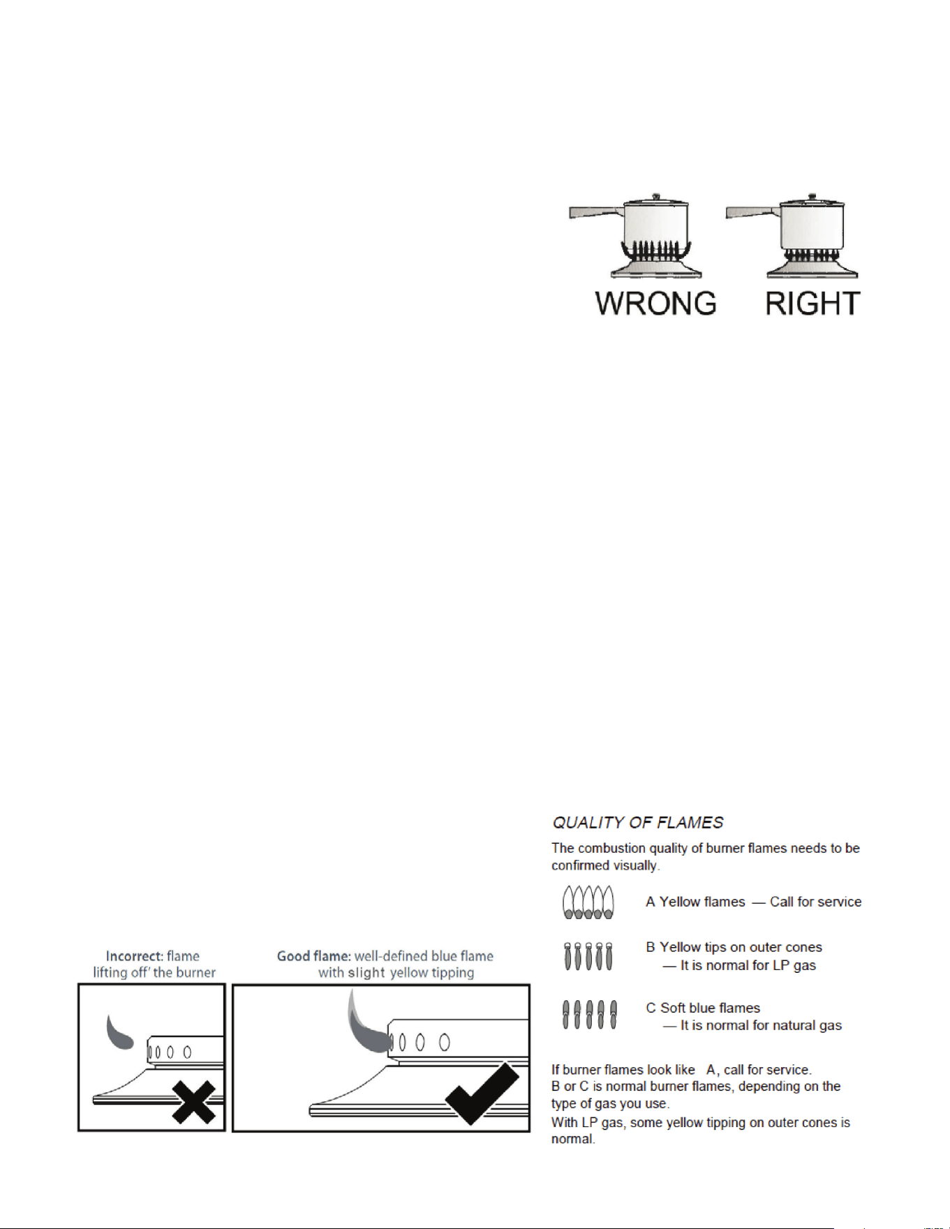
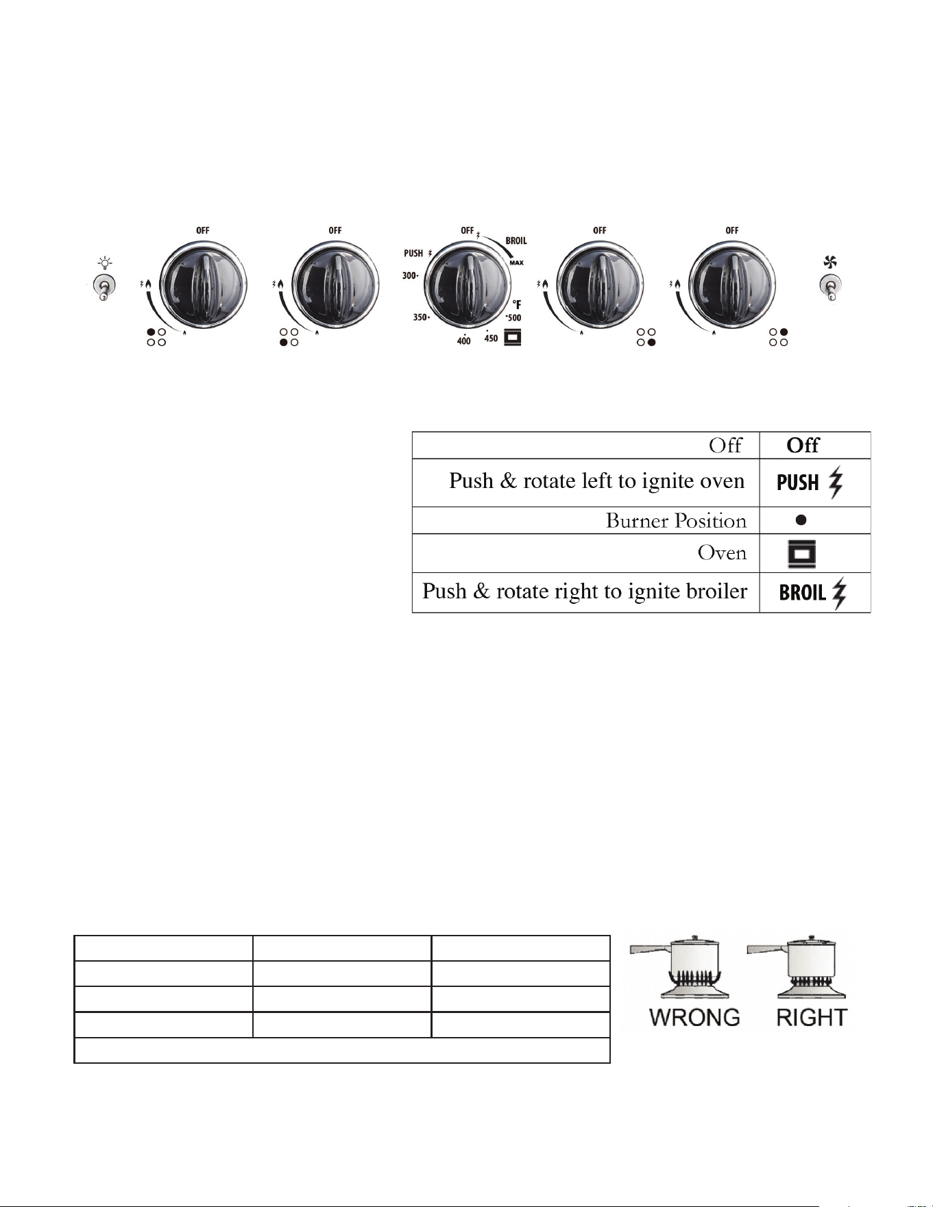
Cooktop Burner Operation
Thetopburneramesizeshouldbeadjustedso
that is does not extend beyond the edge of the
cookware. As a matter of safety, it’s recommended
that you comply with these instructions.
Ahighameonasurfaceburnerisbothinefcientandunsafe.Theameshould
always be adjusted so that it is no larger than the bottom of the pan. Fluctuations in
amesizecouldbecausedbypressurevariations,improperlypositionedburners,
damage or debris.
To light a burner, press the burner knob in and turn counter clockwise to high
ame/ignitionposition.Youwillheartheelectronicignitionclickingasyoucontinue
toholdtheknobdownuntiltheamelights.ALLelectrodeswillsparkatarate
of approximately 2 ½ pulses (sparks) per second. Continue to hold the knob
depressed until gas ignites at the burner. Adjust the intensity of top burner heat in
the same manner described above.
Note: In the event the electronic ignition system fails, the top burners and oven
pilot can be lit by holding a lighted match near the burner head and turning the
appropriate top burner knob to the “9 o’clock position”.
TOP BURNER HEIGHT
ADJUSTING THE TOP BURNER AND OVEN FLAME
(continued)
incorrect and good flame patterns
27
28
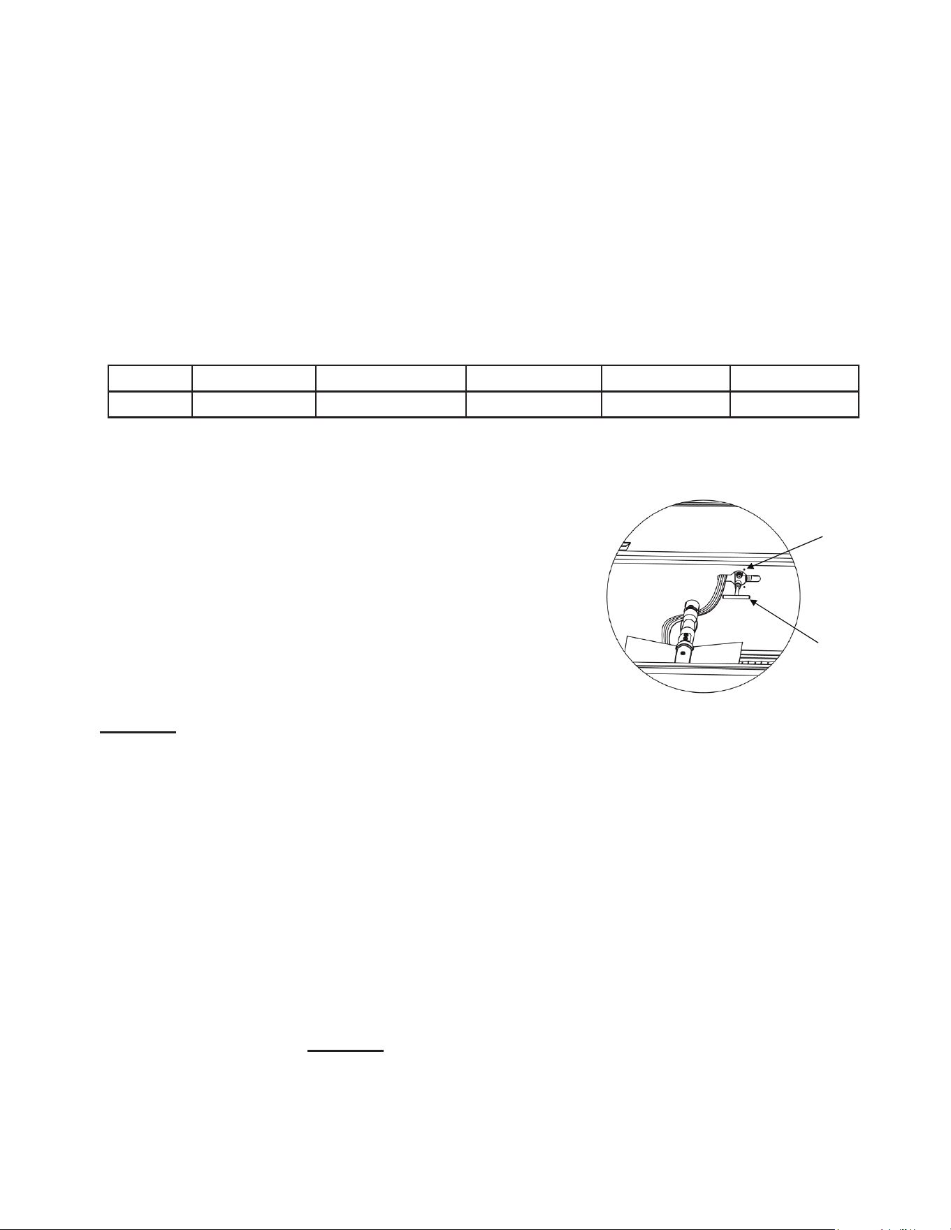
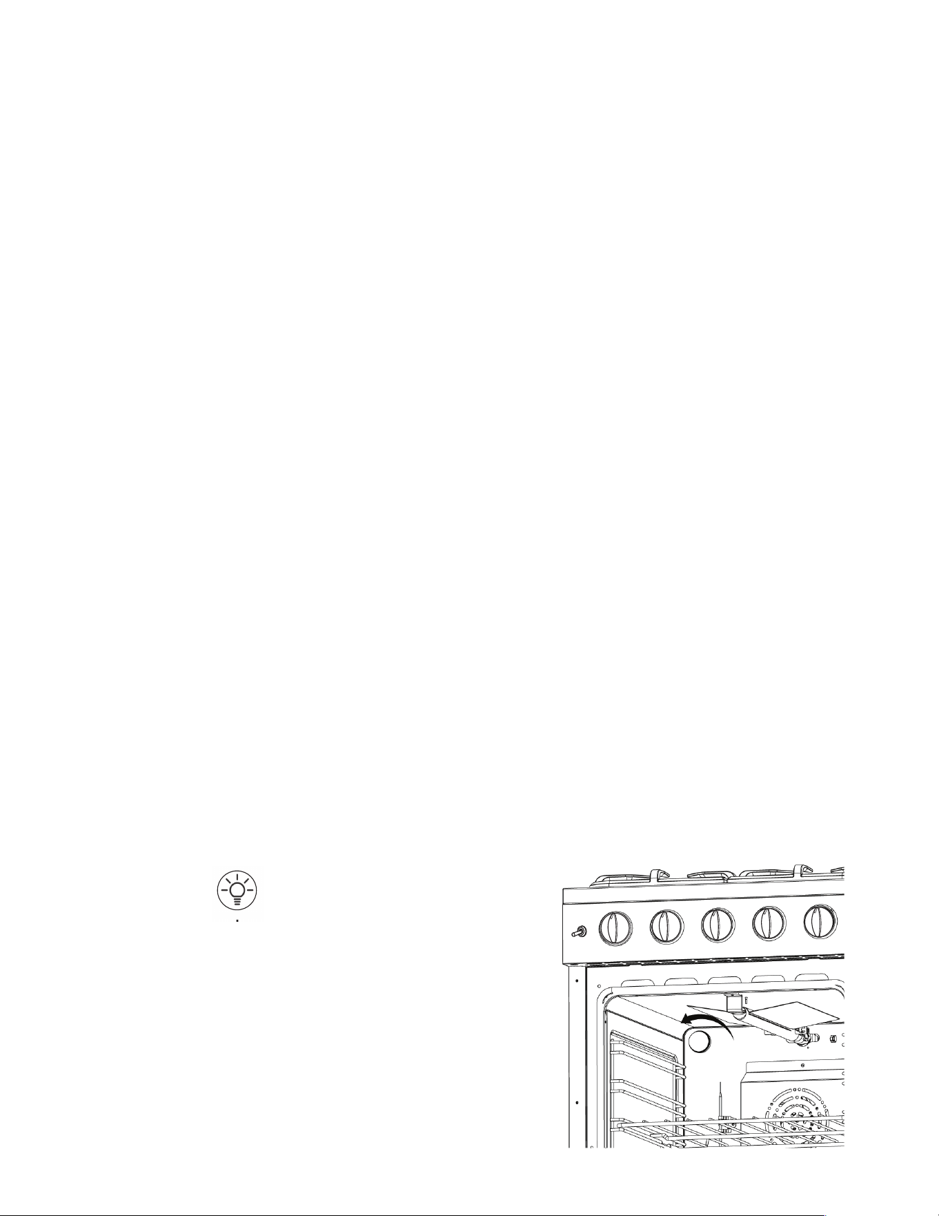
ADJUSTING THE OVEN BURNER FLAME
1) Light the burner by turning the thermostat to the 500ºF position,
2) Remove the knob by pulling straight out.
3) Remove the two (2) Phillips head screws that secure the bezel to the control
panel.
4) Carefully lift the bezel away from the control panel to allow access to the access
hole below the valve stem. (see illustration).
5)Inserttheatheadscrewdriver(2.5mmx75mm)intothescrewholeandturn
the bypass screw clockwise to adjust the
ame.
DO NOT OVERTIGHTEN.
6) Mount the knob to the valve stem.
7) Allow the oven to heat up for approximately 10 minutes then rotate the knob to
the 300ºF position to operate the thermostat by-pass. Slowly screw the by-pass
screwuntilyouobtainaameofapproximately3–4mminheight.
8) Carefully replace the bezel and knob ensuring not to damage wires.
OVEN VALVE
Theovencontrolhasaamesafetydevicebuiltintothebodyofthethermostat.
Presenceofagasignitionsource(pilot)isveriedbyaamesafetyprobe.This
amesafetyprobeactuatestheinternalsafetydevicetoallowgasintotheoven
burner when the oven is turned on. If there is a loss of gas ignition during operation,
theamesafetydevicewillcloseoffgasowtotheovenburnerandpilot.
Theovenburneroriceislocatedonabrassinjectorstudattherearoftheoven
undertheovenoor.Thisoriceisdedicatedtothegasforwhichtheovenistobe
used.Theoriceisnotadjustable.Itmustbechangedcompletelytoconvertfrom
one gas to the other. DO NOT DISCARD THE UNUSED ORIFICE. It should be
saved in order to convert the range back to its original fuel
ADJUSTING THE TOP BURNER AND OVEN FLAME
(continued)
28
29
Lighting the Top Burners
1.Toobtainaamemoreeasily,
light the burner before placing
a cooking utensil on the burner
grate.
2. Decide which burner you’re
ignitingrstusingthescreened
diagram below the burner knob. The black dot indicates the position of the
burner you’re igniting.
3. To light a burner, press the burner knob in and turn counter clockwise to high
ame/ignitionposition.Youwillheartheelectronicignitionclickingasyou
continuetoholdtheknobdownuntiltheamelights.
4.Afterlightingtheame,turnthecontrolknobtoadjusttheamesizeas
required.
Choice of Burner
DIAMETERS OF PANS WHICH MAY BE USED ON THE TOP BURNERS
BURNER MINIMUM MAXIMUM
Auxiliary 4.72”(12 cm) 5.5” (14 cm)
Semi-rapid 6.29” (16 cm) 9.44 (24 cm)
Rapid 9.44” (24 cm) 10.23” (26 cm)
Do not use pans with concave or convex bases
OPERATION OF RANGE
29
24” Model
30
OPERATION OF RANGE
(continued)
HOW TO USE THE GAS OVEN
General features
The gas oven is provided with two burners:
The Oven burner, mounted on the lower part of the oven
The Broil burner, mounted on the upper part of the oven
Using the oven for the rst time
It is advised to follow these instructions:
-Turntheovenontothemaximumtemperatureposition(500˚F)toeliminate
possible traces of grease from the oven burner. The same operation should be
followed for the Broil burner (knob on position BROIL).
- Unplug the power cord, let the oven cool down, then clean the interior of the oven
with cloth soaked in water and detergent (neutral) then dry carefully.
OVEN BURNER
Performs the normal “oven cooking” function.
-Thegasowtotheburnerisregulatedbyathermostatwhichmaintainsthe
desired oven temperature.
- The control of the temperature is determined by a thermostatic probe positioned
inside the oven.
- The probe must be always kept in its housing, in a clean condition, as an incorrect
position or a dirty probe may cause improper control of the temperature.
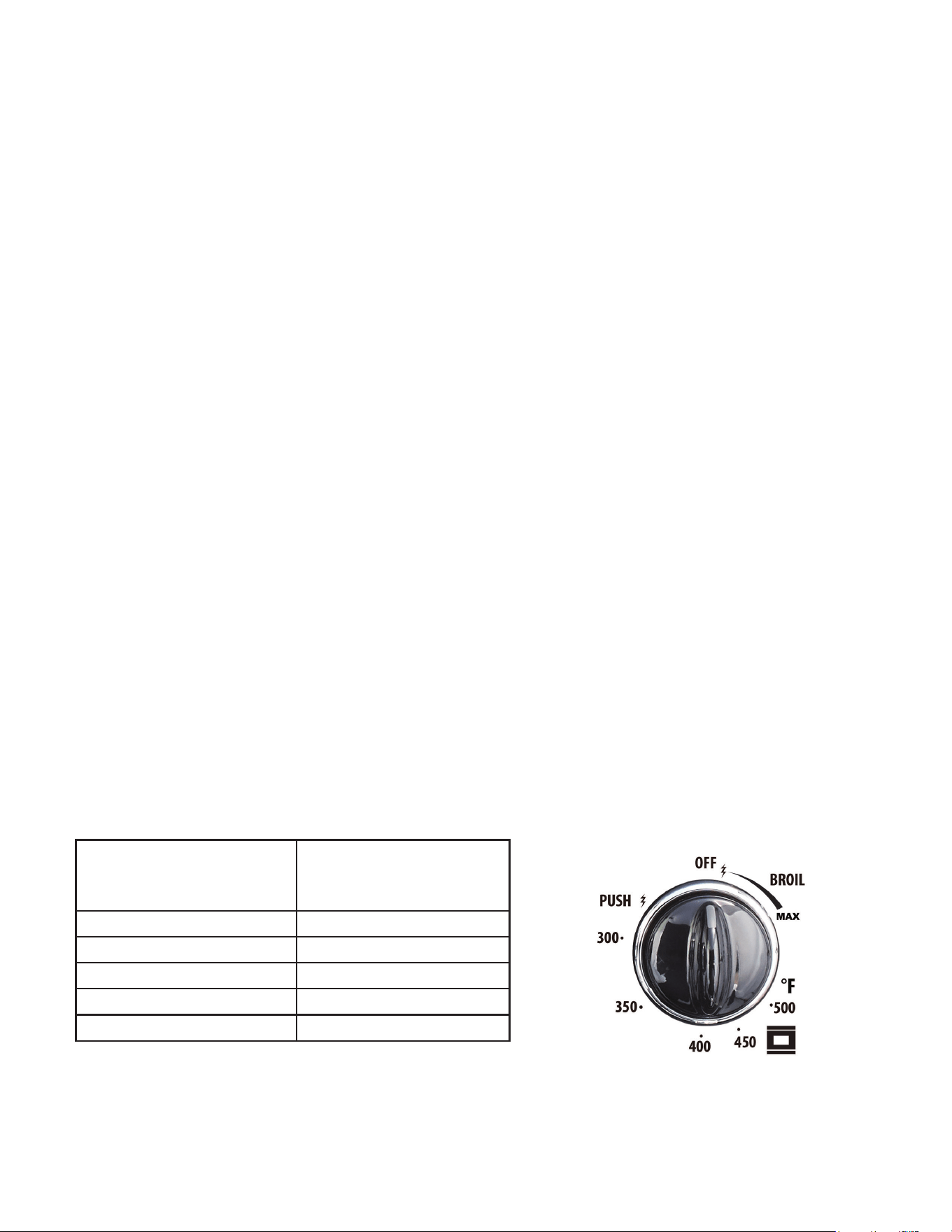
GAS OVEN SETTING
Number printed
on the knob
(temperature in ˚F)
Corresponding
temperature in ˚C
300 149
350 177
400 204
450 232
500 260
30
31
OPERATION OF RANGE
(continued)
OVEN THERMOSTAT
- The numbers printed on the control panel indicate the increasing oven
temperature value (°F).
- To regulate the temperature, set the chosen number onto the control knob
indicator.
- The position BROIL serves only to turn on the broil burner.
NOTE: When the range will not be used for long periods of time, set the gas knobs
to their OFF positions and also close the gas shut-off valve placed on the main gas
supply line.
VERY IMPORTANT: The oven/broil shall be used always with the door
closed.
VERY IMPORTANT: Never obstruct the oven vent slots on the backsplash.
- Important: Use always suitable protective gloves when inserting / removing the
broiling pan, shelves, pans on other cooking utensils from the oven.
- Attention: the range becomes very hot during operation
- Attention: the oven door becomes very hot during operation; be sure to use the
handle to open/close.
- Keep children away from the stove/oven when it is in use.
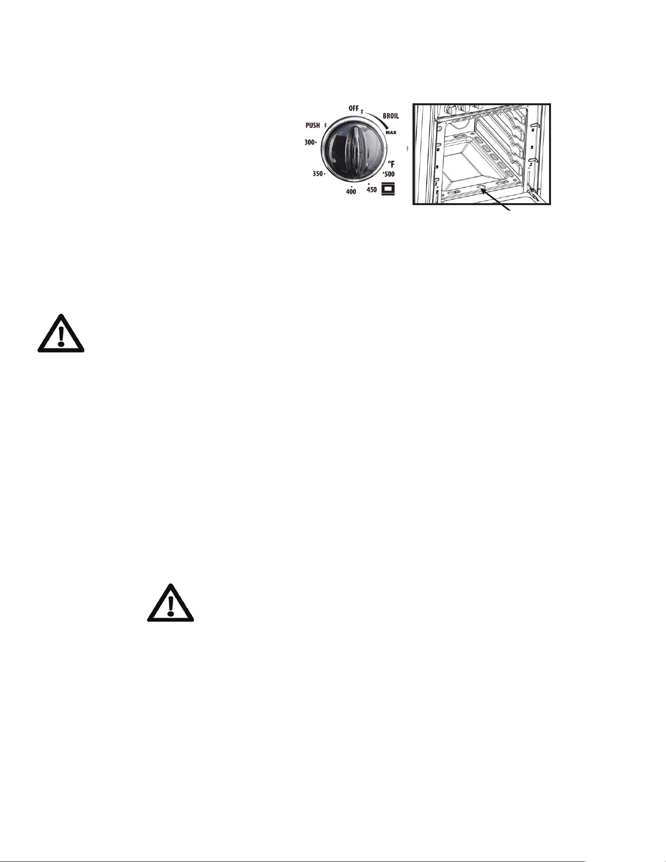
IGNITION OF THE OVEN BURNER
The thermostat allows the automatic control of the temperature.
The gas delivery to the oven burner is controlled by a two way thermostatic tap
(ovenandbroilburners)withame-failuredevice.
To light the oven burner operate as follows:
1. Open the oven door to its full extent.
WARNING: Risk of explosion! The oven door must be open during this
operation.
2. Lightly press and turn the thermostat knob counter-clockwise to max position or
5 0 0 º F.
31
32
3. Press the knob inward and hold
to activate the electronic ignition.
Note that you will hear a “clicking”
noise. Hold the knob pressed
inward until the oven burner is lit.
Once the oven burner is lit, release
the knob.
In case of power outage, you can manually light the burner by pressing the knob
inward and immediately approach a lighted match to the opening “A” (see the
diagram above).
Never continue this operation for more than 15 seconds. If the
burner has still not ignited, wait for about 1 minute prior to
repeating the ignition.
4.Whenusingtherangeforthersttimeorafterlongperiodofnon-usage,keep
pressing the knob inward for approximately 10 – 15 seconds after the burner has lit
to ensure the gas valve has been accurately primed.
5. Close the oven door slowly and adjust the burner accordingly to the desired
temperature.Iftheameextinguishesforanyreason,thesafetyvalvewill
automatically shut off the gas supply to the burner.
Tore-lighttheburner,rstturntheovencontrolknobtotheOFFposition,waitforat
least 1 minute and then repeat the lighting procedure.
Attention: the oven door becomes very hot during operation. Keep
children away.
MOISTURE IMPORTANT
If sparking does not occur when the oven thermostat knob is turned on during the
initial attempt to use, or after several days of non-use, it COULD BE the result of
moisture build-up in the ceramic sleeve of the oven electrode. This may happen
in areas with high humidity, or if food having high water content is cooked. This
moisture can be driven out of the ignitor by lighting the pilot and operating the oven
for a few minutes.
OPERATION OF RANGE
(continued)
A
32

33
OPERATION OF RANGE
(continued)
CONVECTION MODE
Heat is transferred from the bake burners in the bottom of the oven cavity to the
oven cavity itself. The convection fan in the rear of the oven then circulates the
hot air, providing even heat distribution throughout the oven. Convection cooking
generally provides a more even temperature with faster baking times than the
standard oven baking setting. This mode is controlled by a switch on the right hand
sideofthecontrolpanel.Simplyicktheswitchintoactivateit.
• Position the oven’s bottom cover and the oven shelf/shelves before using the
oven. Use more than one oven shelf for larger baking loads. Remove any unused
shelves and baking utensils from the oven.
• Preheat the oven to the temperature stated in the recipe before baking. Depending
on the temperature needed and the size of the oven, preheating will take 15 - 20
minutes.
• Arrange pans and food items evenly on the shelves. Make sure pans do not touch
each other or the sides of the oven. When baking a single item, always center the
item on the oven shelf, preferably in the center of the oven. If baking on multiple
shelves, make sure to stagger items on the shelves so that one is never directly
above another.
NOTES ABOUT CONVECTION COOKING
Convection cooking generally provides a more even temperature with faster
baking times than the standard oven baking setting. When baking in Convection
Mode, either reduce the temperature stated in the recipe and leave the baking
time unchanged, or reduce the baking time by several minutes and leave the
temperature unchanged. For foods with a baking time of over an hour, reducing
both the temperature and the time slightly may give the best results.
•Darkmetalbakingpansorthosewithadullnishabsorbheatfasterthanshiny
pans, and are excellent for pies, breads and anything that needs browning or a
crisper crust.
•Shinynishorlightcolouredpansmayworkbestforfoodsthatrequirelighter,
moredelicatebrowningoracrispercrustastheyreectsomeheat,creatinga
less intense baking surface.
• Avoid opening the oven door frequently during baking as this affects temperature
andefciency.
33
34
OPERATION OF RANGE
(continued)
CONVECTION ROASTING
When convection roasting, it is important that you use a broiler pan for best
convection roasting results. A broil/roast pan (with a rack) elevates the roast to allow
the hot air to circulate around the meat, sealing in juices for a moist and tender
roast with a richly browned exterior (similar to a rotisserie effect.) The pan is also
used to catch any drippings from the roast, keeping the oven clean and reducing
thechanceofsmokingorare-ups.Theconvectionfancirculatesheatedairevenly
over and around the food, sealing in juices for a moist and tender roast with a richly
browned exterior.
CONVECTION DEFROST
With the temperature control off, a motorized fan in the rear of the oven circulates
air. The fan accelerates natural defrosting of the food without heat. To avoid
bacteria growth, food-borne illness and food waste, do not allow defrosted food to
remain in the oven for more than 2 hours without being cooked.
CONVECTION DEHYDRATE
Withthetemperaturecontrolat175˚F,warmairisradiatedfromthebakeburnersin
the bottom of the oven cavity and is circulated by a motorized fan in the rear of the
oven. Over time, this constant circulating heat evaporates moisture from food, which
inhibits bacteria growth and halts enzyme activity
NEVER LEAVE THE CONTROL KNOBS IN ANY POSITION OTHER THAN
“OFF” IF THE IGNITORS OR BURNERS AREN’T WORKING PROPERLY.
IGNITION OF THE BROIL BURNER
To light the broil burner operate as follow:
1. Open the oven door to its full extent.
WARNING: Risk of explosion! The oven
door must be open during this operation.
2. Lightly press and turn the thermostat knob
clockwise to the broil position.
34
35
3. Press the knob inward and hold to activate the electronic ignition. Note that you
will hear a “clicking” noise. Hold the knob pressed inward until the oven burner
is lit. Once the oven burner is lit, release the knob. In case of power outage,
you can manually light the burner by pressing the knob inward and immediately
approach a lighted match to the area noted in the diagram above. Never
continue this operation for more than 15 seconds. If the burner has still not
ignited, wait for about 1 minute prior to repeating the ignition.
4. Whenusingtherangeforthersttimeorafterlongperiodofnon-usage,keep
pressing the knob inward for approximately 10 – 15 seconds after the burner has
lit to ensure the gas valve has been accurately primed.
5. Slowlyclosetheovendoor.Iftheameextinguishesforanyreason,thesafety
valve will automatically shut off the gas supply to the burner.
Tore-lighttheburner,rstturntheovencontrolknobtotheposition,waitforat
least 1 minute and then repeat the lighting procedure.
Always broil with oven door closed. Attention: the oven door becomes
very hot during operation. Keep children away.
BROILING
Very important: the broil burner must always be used with the oven door
closed.
Position the oven rack on the second level from the top
1. Turn on the broil burner, as explained in the preceding paragraphs and let the
broil burner preheat for about 5 minutes with the door closed.
2. Place the food to be cooked below the broiler.
OVEN LIGHT
The range is equipped with a light that illuminates
the oven to enable visually controlling the food that
is cooking. This light is controlled by a switch on
thelefthandsideofthecontrolpanel.Simplyick
the switch to activate the light.
CHANGING OVEN LIGHT BULB
Remove light bulb cover and unscrew light bulb
counter clockwise. Replace with an E14 120V
25W 300°C bulb.
OPERATION OF RANGE
(continued)
The range is equipped with a light that illuminates
35
36
GENERAL RECOMMENDATION
Electrical Shock Hazard
• Plug into a grounded 3-prong
outlet. Insure proper ground
exists before
using the range.
• Do not remove ground prong.
• Do not use an adapter or
extension cord.
• Failure to follow these instructions can result in death, re, or electrical
shock.
Important: Before any operation of cleaning and maintenance disconnect the
appliance from the electrical supply.
It is advisable to clean when the appliance is cold and especially for cleaning the
enameled parts.
Avoid leaving alkaline or acidic substances (lemon juice, vinegar, etc.) on the
surfaces. Avoid using cleaning products with a chlorine or acidic base.
The oven must always be cleaned after every use, using suitable products and
keeping in mind that its operation for 30 minutes on the highest temperature
eliminates most grime reducing it to ashes.
Always keep cleaning materials and chemicals in a safe place and away from
children. Know what you are using. Make sure all parts of the range are COOL
before cleaning. Be sure to replace the parts correctly.
Knobs
Pull forward on the knobs to remove them. Wash in a water solution with a mild
detergent mix. Do not use an abrasive cleaner or any abrasive action. Abrasive
action will scratch the knobs.
If the knobs become loose on the valve stem, spread the valve stem slightly with a
small screwdriver.
CLEANING THE RANGE
! !
WARNING
36

37
Using Commercial Oven Cleaners
Commercial oven cleaners may be used on porcelain lined ovens; however, many
cleaners are very strong, and it’s essential to follow instructions carefully. Be sure to
wear rubber gloves to protect your hands.
After using such cleaners, thoroughly rinse the oven with a solution of 1 tablespoon
vinegar to 1 cup of water. Oven cleaners can coat or damage the thermostat sensing
device (the long tube in the oven) so that it will not respond to temperature accurately.
If you use an oven cleaner, do not let it contact the sensing bulb, or any chrome,
aluminum, or plastic part of the range.
Do not apply or allow the cleaner to come in contact with any parts or surfaces
other than the oven interior.
Grates, Main Tops, Surface Burners
The grates are made of porcelain coated steel. These materials can be cleaned at the
sinkwithdetergentorsoap-lledscouringpads.Donotbealarmedwhenthegrate
losesitsshinynish.Theheatfromtheburnerswillcausethegratestolosetheir
shinynish.
Clean the burner with soap and water, rinse thoroughly and dry completely before
reassembling. Burner heads can be dried in the oven at about 350 degrees Fahrenheit
or in the dishwasher on the dry cycle. After adjustment or cleaning, replace all parts to
their original position.
Stainless Steel Elements
Thestainlesssteelnishtopcanbecleanedwithdetergentandwarmwater.
Stainless steel parts must be rinsed with water and dried with a soft and clean cloth or
with a chamois leather.
Fordifcultgrime,useacommerciallyavailable,non-abrasiveproductforcleaning
stainless steel surfaces, or a little hot vinegar.
Note: regular use could cause discoloring around the burners, because of the high
ametemperature.
Products of combustion from the top pilots as well as certain atmospheric conditions
can create an oxidation reaction on the underside of the top. This will appear as rust
or in the form of a reddish brown deposit. This will NOT AFFECT THE LIFE OF THE
TOP in comparison to the general life expectancy of the range itself.
It is very important that the burner be dry before replacing it in the range. A wet burner
will not allow the gas to ignite properly. This could result in a build-up of gas which
couldresultinanexplosionorre.
CLEANING THE RANGE (continued)
37

38
Aluminum Foil in Oven
NEVER cover any slots, holes or passages in the oven bottom or
cover an entire rack with materials such as aluminum foil. Doing so
blocks air ow through the oven and may cause carbon monoxide
poisoning. Aluminum foil linings may also trap heat, causing a re
hazard.
Aluminiumfoilwhenusedimproperlyisacauseofmanyrangeres.
Make certain that vents or air openings aren’t covered by the foil. If
the vents located along the sides of the oven bottom are blocked, poor
cooking will result.
Never cover a rack completely. A piece of foil slightly larger than the
cookware can be placed on the rack beneath the cookware.
Remove and discard aluminum foil after each use. This will help prevent
greaseandspilledfoodfromaccumulatingandbecomingarehazard.
Cleaners and Cleaning Materials
Do not use harsh cleaners or degreasers on or around functional parts
(valves, controls, etc., or aluminum tubing). This will damage or drastically
reduce the life of the part.
Use only a mild solution of soap and water on backguards, aluminum
control panels and painted surfaces. Never use harsh abrasives or
cleaning powders that may scratch or mar the surface. Make sure the
cleaners and cleaning materials are suitable for use on the area to be
cleaned. Always keep cleaning materials in a safe place. Never use a
sharp metal scraper to clean glass, porcelain, or painted surfaces.
CARE AND MAINTENANCE
!
!
WARNING

39
CARE AND MAINTENANCE
(continued)
Repair Parts
When repair parts are needed, contact the dealer from whom the range
was purchased. In case your range was purchased from a source other
than an appliance dealer, you may prefer to contact the manufacturer at
the address shown in this manual.
Moisture
During the initial heat-up of your range, the heat mixing with the cooler air
in the oven cavity may produce fogging of the door glass or a collection
ofwateronthedoor.Topreventthis,opentheovendoorfortherstfew
seconds of initial oven heat-up. This will allow the moist air within the
oven to escape, without the forming of visible moisture on the range. The
amount of moisture will depend upon the humidity of the air and water
content of the food being cooked. Fogging and even dripping water will
usually occur in geographic locations of high humidity.
BURNERS AND CAST-IRON GRIDS
• These parts can be removed and cleaned with appropriate products.
• Aftercleaning,theburnersandtheiramedistributorsmustbewelldriedand
correctly replaced.
• Itisveryimportanttocheckthattheburneramedistributorandthecaphas
been correctly positioned - failure to do so can cause serious problems.
• In appliances with electric ignition keep the electrode clean so that the sparks
always strike.
Note: To avoid damage to the electric ignition do not use it when the
burners are not in place.
40
CORRECT REPLACEMENT OF THE BURNERS
Itisveryimportanttocheckthattheburnerame
spreader “F” and the cap “C” have been correctly
positioned. Failure to do so can cause serious
problems. In appliances with electric ignition, check
that the electrode “S” is always clean to ensure
trouble-free sparking.
The ignition plug must be cleaned very carefully.
OVEN RACK INSTALLATION AND REMOVAL
• The oven racks are provided with a safety catch to prevent accidental removal.
• They must be inserted as shown.
• To pull them out remove the rack in the reverse order.
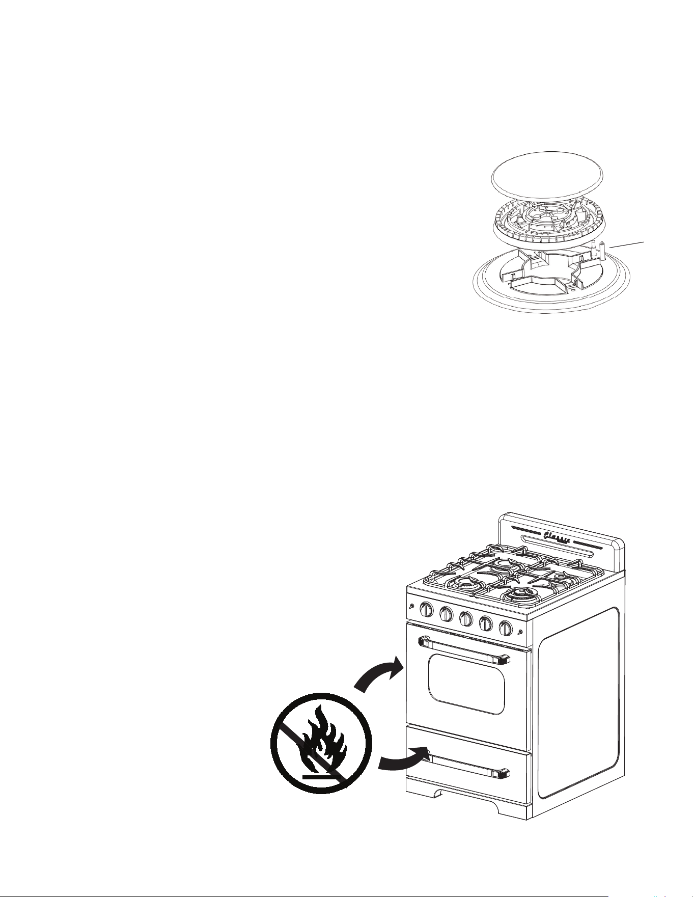
DO NOT STORE FLAMMABLE MATERIAL IN THE OVEN OR IN THE BOTTOM
DRAWER.
Only store heat resistance
pots, pans, and trays in the
drawer as it gets very hot
when the oven is on.
Do not store plastic items (or
pots and pans with plastic
handles) in your drawer.
CARE AND MAINTENANCE
(continued)
C
F
S
41
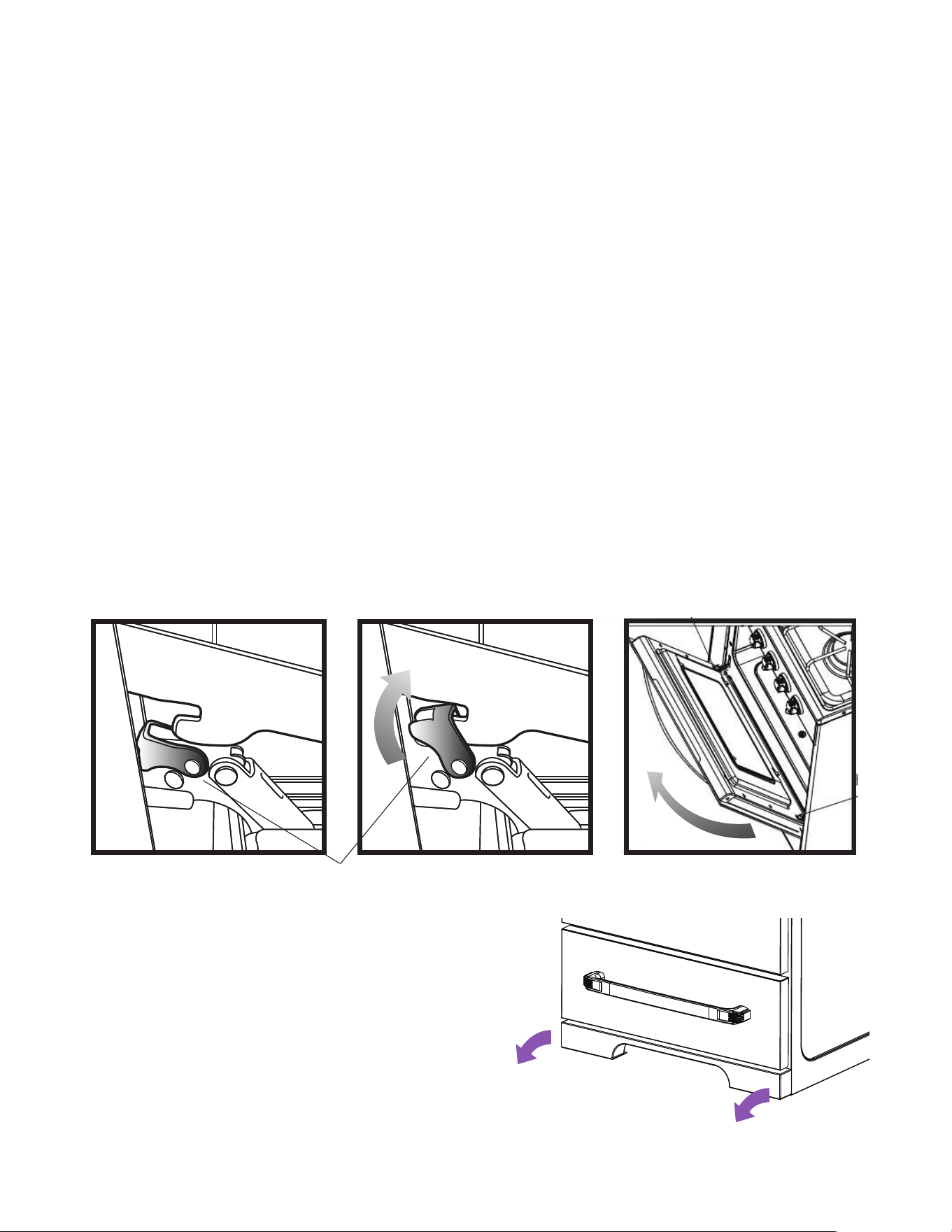
REMOVING THE OVEN DOOR FOR CLEANING
To facilitate oven cleaning, it is possible to remove the door. Please follow the
instructions carefully:
The oven door can easily be removed as follows:
• Open the door to fully.
•Lifttheleftandrighthooksonthehingegure(A,B).
•Holdthedoorasshowningure(C)ona45degreeangle.
• Gently close the door until the hooks touch the door, then lift at a 45 degree angle
•Setthedooronasoftatsurface.
• To replace the door, repeat the above steps in reverse order.
REMOVING THE KICKPLATE
FOR CLEANING
It is possible to remove the magnetic
kickplate at the bottom of the range to aid
in cleaning underneath the range.
CARE AND MAINTENANCE
(continued)
hook
(C)(B)(A)
42
CARE AND MAINTENANCE
(continued)
REPLACING THE OVEN LIGHT
• Let the oven cavity and broil burner cool down.
• Switch off the electric supply.
• Remove the protective cover.
• Unscrew and replace the bulb with a new one suitable for high temperature
(200°~500°F)havingthesamespecications:E14120V25W300°C.
• Replace the protective cover.
NOTE: Oven bulb replacement is not covered by your guarantee.
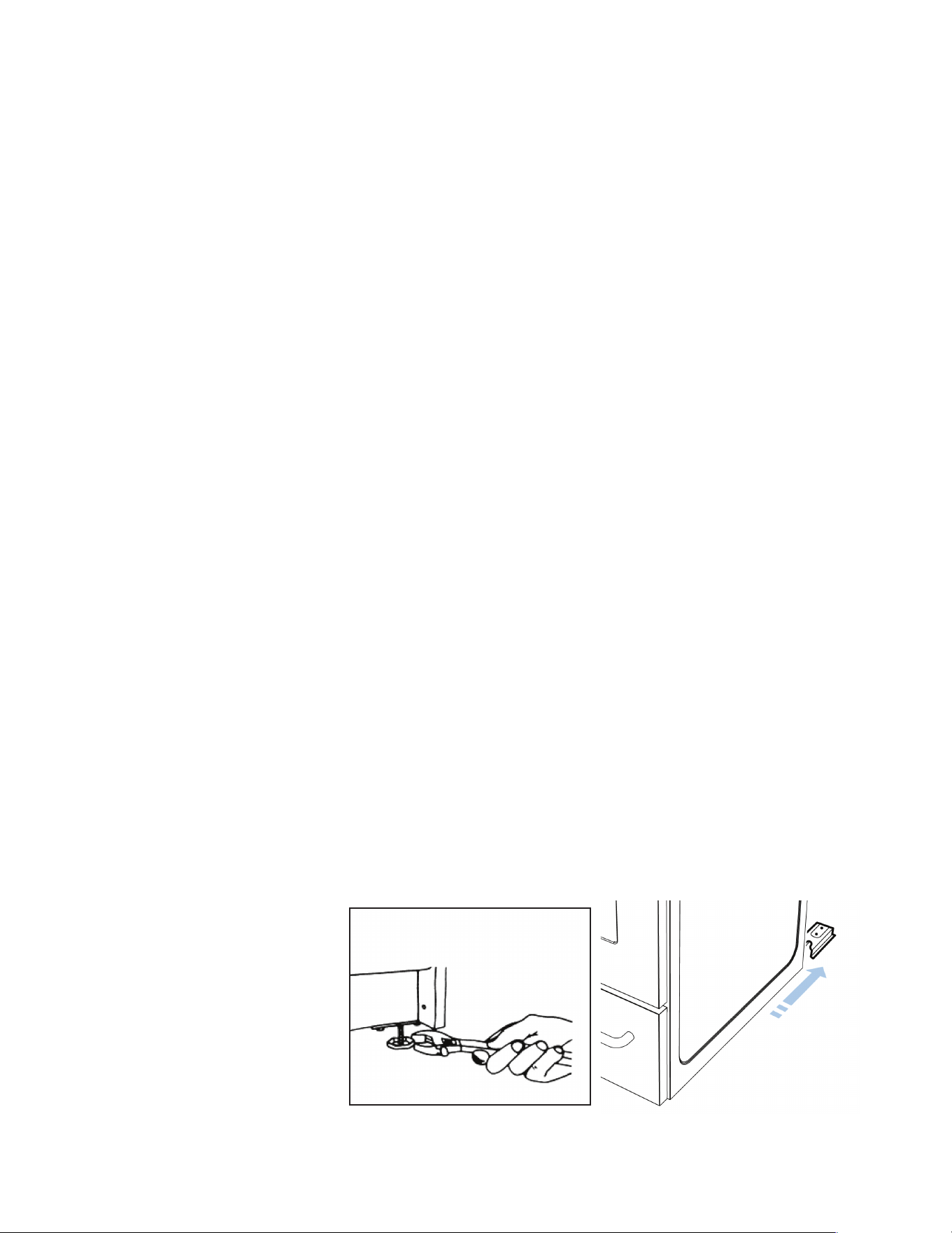
LEVELING THE RANGE
The range must be level to obtain proper operating. The four screws type
leveling legs located on the corners at the bottom of range should be adjusted
by turning them clockwise to make the range higher or counter-clockwise to
lower the range until the range is level. Use a level on surface units to check
the leveling of the range.
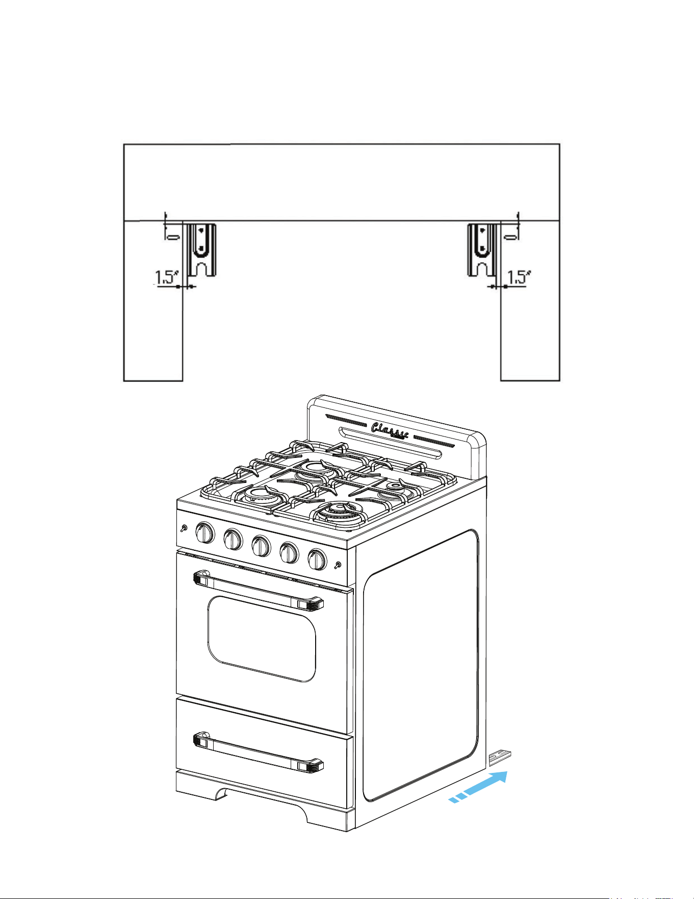
ANTI-TIP BRACKET INSTALLATION
To reduce the risk of tipping the range by abnormal usage or improper door
loading, the range must be secured by properly installing the anti-tip device
packed with the appliance.
•Placetheanti-tipbracketontheoorasshowngure.Anti-tipbracketcanbe
installed on the right and left side.
•Makethelocationsof2(x2)holesofant-tipbracketontheoor.
• Use a drill bit
•Securebrackettooorusingscrewssupplied.
• Slide appliance into position.
NOTE: If range is
relocated, the bracket
must be removed and
installed in new location.
43
TROUBLESHOOTING
PROBLEM POSSIBLE CAUSE POSSIBLE FIX
Surface burners
do not light.
Surface control has not been com-
pletely turned to the ON position.
Push in and turn control to the ON position
until burner ignites, then turn control to de-
siredamesetting.
Burner ports are clogged. Use a small gauge wire or needle to open
ports.
Burners not positioned properly. Verify that the burners are positioned prop-
erlyontheoricehoodsandtheburnersare
sittingatontheburnersupportwithtabs
engaged in slots.
Range not set for appropriate gas
input.
See range conversion section of installation
manual.
Burners won’t light due to power
failure.
Light burners manually.
Range power cord is disconnected
from the outlet.
Be sure power cord is plugged into grounded
outlet.
Flame burns half-
way round.
Burner ports are clogged. Use a small gauge wire or needle to open
ports.
Moisture is present after cleaning. Lightlyfantheameandallowburnertooper-
ateuntilameisfull.ORdryburnersthor-
oughly following instructions in range “Clean-
ing” section.
Range is not set for appropriate gas
input.
See range conversion section of installation
manual.
Flame is orange.
Dust particles in main line. Allow burner to operate for a few minutes until
ameturnsblue.
Range is not set for appropriate gas
input.
See range conversion section of installation
manual.
Oven light does
not work.
Burned out or loose bulb Tighten or replace oven light bulb.
Oven or broiler
does not heat.
Range is not set for appropriate gas
input.
See range conversion section of installation
manual
Temperature control not set properly. Make sure temperature control is set at de-
sired temperature.
Burners will not light due to power
failure.
Light burners manually.
House fuse has blown or circuit
breaker has tripped.
Check/reset circuit breaker and/or replace
fuse. Do not increase fuse capacity. If the
problem is a circuit overload, have it corrected
byaqualiedelectrician.
Range cord is disconnected from
outlet.
Be sure the power cord is plugged into a
grounded outlet.
44
PROBLEM POSSIBLE CAUSE POSSIBLE FIX
Oven temperature is
inaccurate.
Oven capillary bulb not positioned
properly.
Verify that capillary bulb is snapped in clips
straight and not touching sides or coated
with oven cleaner or food.
Temperature control not set properly. Make sure the temperature control knob is
set at the desired temperature.
Improper use of foil. Keep foil clear of holes in oven bottom and
off of oven sides.
Vent blocked. Keep vent on backguard clear.
Range not set for appropriate gas
input.
See range conversion section of
installation manual.
Smoke/odor on initial
oven operation
This is normal.
Range is not level Poor installation. Place oven rack in centre of oven. Place a
level on the rack. Adjust leveling legs.
Weakorunstableoor. Besureoorislevelandcanadequately
support range. Contact carpenter to
correctsaggingorslopingoor.
Kitchen cabinet misalignment may
make range appear to be unlevel.
Be sure cabinets are square and have
sufcientroomforrangeclearance.
Contact cabinet maker to correct problem.
Oven smokes
excessively
Meat too close to broiler burner. Reposition the broiler pan to provide more
clearance between the meat and the
broiler burner.
Meat not prepared properly. Remove excess fat from meat.
TROUBLESHOOTING
(continued)
45
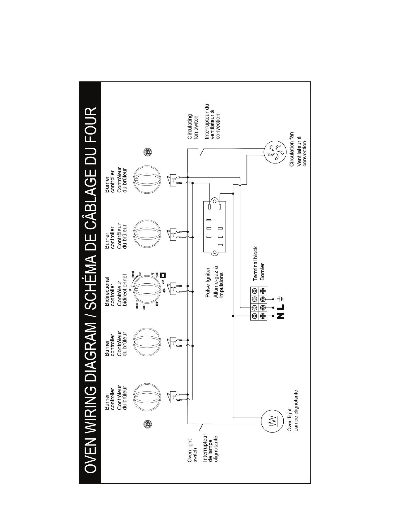
24”
WIRING DIAGRAM
46
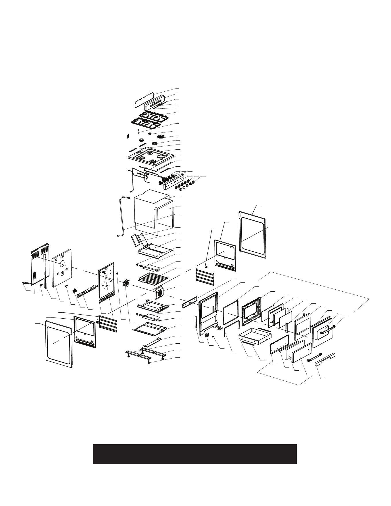
24” PARTS DIAGRAM AND LIST
Please visit our website www.uniqueappliances.com to view a PDF
version of the schematics which will allow you to zoom in & out
1
3
4
6
7
8
10
11
2
5
9
12
13
14
15
16 17 18
19 20 21
22
23
24
25
26
27
28
29
30
31
32
33
34
35
36
37
39
40
67
69
70
71
72
73
74
75
50
49
48
47
45
44
43
41
52
53
55
56
57
58
59
60
62
54
76
77
78
80
81
66
65
38
46
51
61
63
64
79
68
42
82
83
47
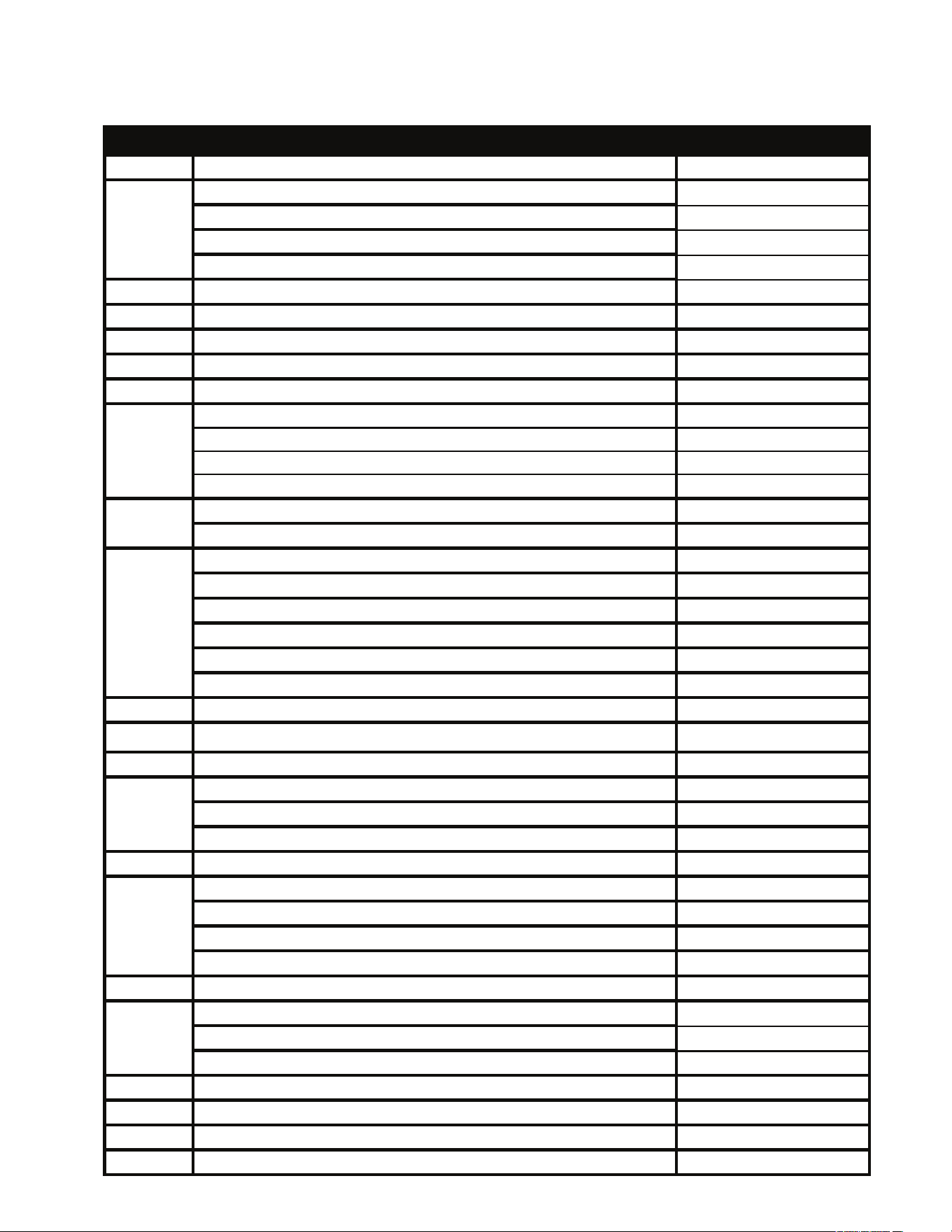
24” PARTS DIAGRAM AND LIST
I
I
T
T
E
E
M
M
#
#
DDEESSCCRRIIPPTTIIOONN MMOODDEELL ##
1
Backsplash Back Cover Plate for UGP-24CR all colours UGP-CY99101
Backsplash + Logo Black for UGP-24CR B UGP-QJG05009
Backsplash + Logo White for UGP-24CR W UGP-QJG05008
Backsplash + Logo Light Green for UGP-24CR LG UGP-QJG05007
Backsplash + Logo Turquoise for UGP-24CR T UGP-QJG05010
3 Left Logo Wing for UGP-24CR all colours UGP-CY99110
4 Classic Retro Logo for UGP-24CR all colours UGP-CY99109
5 Right Logo Wing for UGP-24CR all colours UGP-CY99111
6 Cast Iron Grate Set (with Dimplets) for UGP-24G/24/24CR UGP-DWWJ01019-1
7 Backsplash Fixed Plate for UGP-24G/24/24CR UGP-CY14516
8 Small Burner UGP-24CR all colours UGP-QJG05020
9 Dual Burner UGP-24CR all colours UGP-QJG05022
10 Medium Burner UGP-24 all colours UGP-QJG05021
11 Backsplash Mount Plate UGP-24CR UGP-CY14515-1
Cooking panel (Stove Top) White for UGP-24CR W UGP-WSJ07027-W
Cooking panel (Stove Top) Black for UGP-24CR B/LG/T UGP-WSJ07027-B
right rear gas pipe UGP-DWWJ01312
right front gas pipe UGP-DWWJ01313
left rear gas pipe UGP-DWWJ01314
left front gas pipe UGP-DWWJ01315
oven bottom gas pipe UGP-DWWJ01316
oven top gas pipe UGP-DWWJ01334
14 main gas pipe UGP-DWWJ01311
15 Cooking Panel (Stove Top) Stop Plate for 20/24/24CR ON1 UGP-CY14226
16 Thermostat Valve for 24/24CR ON1 UGP-DWWJ01114-6
gas valve 0.45 UGP-DPJ99170
gas valve 0.55 UGP-DPJ99171
gas valve 0.68 UGP-DPJ99172
18 Toggle Switch UGP-24CR all colours UGP-KG9923
Control Panel Black for UGP-24CR B UGP-WSJ13340-5SY-01
Control Panel White for UGP-24CR W UGP-WSJ13340-4SY-01
Control Panel Light Green for UGP-24CR LG UGP-WSJ13340-6SY-01
Control Panel Turquoise for UGP-24CR T UGP-WSJ13340-7SY-01
20 Knob Bezel for UGP-24CR all colours UGP-CY07050
Knob White for UGP-24CR W UGP-QJG05018
Knob Black for UGP-24CR B and LG UGP-QJG05019
knob embedded block UGP-DWWS07023-1
22 inner liner heat-resistance board UGP-WSJ13347
23 inner liner heat-resistance cotton UGP-DPJ99004-1
24 Bellow for UGP-30G/20/24/24CR ON1 Ranges UGP-DWWJ01002
25 Chimney A for 20/24/24CR ON1 UGP-CY14536
21
2
12
13
17
19
48
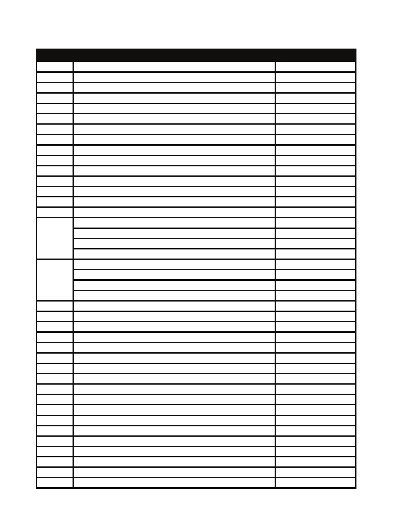
24” PARTS DIAGRAM AND LIST
I
I
T
T
E
E
M
M
#
#
DDEESSCCRRIIPPTTIIOONN MMOODDEELL ##
26 Chimney B for 20/24/24CR ON1 UGP-CY14537
27 inner liner top board UGP-WSJ13342-1
28 Nozzle Seat for UGP-30G/20 & 24/24CR ON1 UGP-DPJ24070
29 Oven/Broiler Flame Spreader UGP-24CR UGP-CY04248
30 Oven Upper Burner for 24/24CR ON1 UGP-DWWJ01335
31 Cooking Grid (Oven Rack) for 24/24CR ON1 UGP-DWWJ01012-3
32 Fan Cover for 20/24/24CR ON1 UGP-WSJ13348
33 Oven Floor for 24/24CR ON1 UGP-WSJ13343
34 Ignition Needle Bracket for 20/24/24CR ON1 UGP-CY14543
35 Bottom Burner for UGP-24G/20 & 24/24CR ON1 UGP-DWWJ01317
36 Middle Heat-Insulated Panel for 24/24CR ON1 UGP-WSJ13347
37 Bottom Fixed Board for 24/24CR ON1 UGP-CY14544
38 Feet Fasten Beam (Left) for 20/24/24CR ON1 UGP-CY14237
39 Feet Fasten Beam (Right) for 20/24/24CR ON1 UGP-CY14238
40 Adjustable Feet for UGP-24G/24CR/30G/20 & 24 ON1 UGP-DWWJ01010
Bottom Decorative (Kick Plate) Panel For UGP-24CR White UGP-WSJ07031-W
Bottom Decorative (Kick Plate) Panel For UGP-24CR Light Green UGP-WSJ07031-LG
Bottom Decorative (Kick Plate) Panel For UGP-24CR Black UGP-WSJ07031-B
Bottom Decorative (Kick Plate) Panel For UGP-24CR Turquoise UGP-WSJ07031-T
Drawer Outer Panel for 24CR Black UGP-WSJ07028-B
Drawer Outer Panel for 24CR White UGP-WSJ07028-W
Drawer Outer Panel for 24CR Light Green UGP-WSJ07028-LG
Drawer Outer Panel for 24CR Turquoise UGP-WSJ07028-T
43 Drawer Heat-Insulated Fiber for 24/24CR ON1 UGP-DPJ99004-4
44 Drawer Decorative Plate for UGP-24CR all colours UGP-CY99106
45 Drawer Inner Panel for UGP-24CR all colours UGP-WSJ13345-2
46 Slider for 20/24/24CR UGP-DWJ10100
47 Drawer for 24/24CR ON1 UGP-WSJ13346
48 Broiler Seal (Gasket) for UGP-24G/24/24CR UGP-DWWJ01018-1
49 Magnet for UGP-24CR UGP-DWJ9945-4
50 Kick Plate Panel Support for UGP-20G/24CR UGP-CY14266
51 Hinge Base for UGP-24CR UGP-DWWJ01345-1
52 Convection Fan for 20/24/24CR ON1 UGP-DQT01367
53 Thermostat Clip for 20/24/24CR ON1 UGP-CY14249
54 Light for 20/24/24CR ON1 UGP-DPJ99188
55 Liner Back Panel for 24/24CR ON1 UGP-WSJ13341
56 Liner Fasten Beam for 24/24CR ON1 UGP-CY14538
57 Gas Regulator for UGP-20G/24G/30G OF & 24/24CR ON1 UGP-DPJ24060
58 Gas Regulator Fixed part for 20/24/24CR UGP-CY14271
59 Liner Heat-Insulated Fiber (Back) for 24/24CR UGP-DPJ99004-3
60 Back Panel Fixed Support for 20 & 24/24CR UGP-DCY14250
41
42
49
24” PARTS DIAGRAM AND LIST
I
I
T
T
E
E
M
M
#
#
DDEESSCCRRIIPPTTIIOONN MMOODDEELL ##
61 Terminal Block for 20/24/24CR ON1 UGP-JXZ0200
62 Pulse Ignition for 20/24/24CR ON1 UGP-DXQJ9977-2
63 Power Cord for 20/24/24CR ON1 UGP-DX0231
Oven/Drawer Handle ASSY Black for UGP-24CR B UGP-QJG05012
Oven/Drawer Handle ASSY White for UGP-24CR W UGP-QJG05013
Oven/Drawer Handle ASSY Light Green for UGP-24CR LG UGP-QJG05011
Oven/Drawer Handle ASSY Turquoise for UGP-24CR T UGP-QJG05014
65 Oven/Drawer Handle Base(Left&Right) for UGP-24CR UGP-CY99112
Oven Door Outer Panel Black for UGP-24CR B UGP-WSJ07024-B
Oven Door Outer Panel White for UGP-24CR W UGP-WSJ07024-W
Oven Door Outer Panel Light Green for UGP-24CR LG UGP-WSJ07024-LG
Oven Door Outer Panel Turquoise for UGP-24CR T UGP-WSJ07024-T
67 Oven Door Heat-Insulated Fiber for 24/24CR UGP-DPJ99006-1
68 Oven Door Hinge Assembly for UGP-24CR UGP-DWWJ01016-2
69 Middle Glass Fixed Plate for UGP-24CR UGP-CY99122
70 Inner Glass Fixed Plate for UGP-24CR UGP-CY99121
71 Oven Door Glass for UGP-24G OF1/24/24CR ON1 UGP-DQT01003-1
72 Oven Door Inner Panel for UGP-24CR UGP-WSJ13262-1
73 Oven Seal (Gasket) for UGP-24G/24/24CR ON1 UGP-DWWJ01014-1
74 Liner Front Panel for UGP-24CR UGP-DWSJ07022
75 Burner Fixed Board for 24/24CR ON1 UGP-CY14531
Right Side Panel Black for UGP-24CR B UGP-WSJ07026-B
Right Side Panel White for UGP-24CR W UGP-WSJ07026-W
Right Side Panel Light Green for UGP-24CR LG UGP-WSJ07026-LG
Right Side Panel Turquoise for UGP-24CR T UGP-WSJ07026-T
77 Liner Right Panel for 20/24/24CR ON1 UGP-WSJ13350
78 Oven Rack Fixed Part for 20/24/24CR ON1 UGP-CY14270
79 Oven Rack Support for UGP-20G/24G/20 & 24/24CR ON1 UGP-DWWJ01011-1
80 Liner Left Panel for 20/24/24CR ON1 UGP-WSJ3349
Left Side Panel Black for UGP-24CR B UGP-WSJ07025-B
Left Side Panel White for UGP-24CR W UGP-WSJ07025-W
Left Side Panel Light Green for UGP-24CR LG UGP-WSJ07025-LG
Left Side Panel Turquoise for UGP-24CR T UGP-WSJ07025-T
Oven Door ASSY White For UGP-24CR W UGP-DQJG06020-2
Oven Door ASSY Black For UGP-24CR B UGP-DQJG06020-3
Oven Door ASSY Light Green For UGP-24CR LG UGP-DQJG06020-6
Oven Door ASSY Turquoise For UGP-24CR T UGP-DQJG06020-7
Drawer Door ASSY White For UGP-24CR W UGP-QJG05023
Drawer Door ASSY Black For UGP-24CR B UGP-QJG05017
Drawer Door ASSY Light Green For UGP-24CR LG UGP-QJG05015
Drawer Door ASSY Turquoise For UGP-24CR T UGP-QJG05016
82
83
64
66
76
81
50
APPLIANCE INFORMATION
(manual copy - keep with your records)
APPLIANCE INFORMATION
(remote copy - keep with your appliance)
detatch along dotted line detatch along dotted line
detatch along dotted line detatch along dotted line
T
omakecareandservicingofyourrangeeasyandefcient,pleaserecordthefollowing
information for future reference:
Model:
Serial Number:
Purchased From:
Date Purchased:
Installed By:
Tomakecareandservicingofyourrangeeasyandefcient,pleaserecordthefollowing
information for future reference:
Model:
Serial Number:
Purchased From:
Date Purchased:
Installed By:

51
detatch along dotted line detatch along dotted line
CLASSIC RETRO BY UNIQUE 24” CONVECTION GAS RANGE
1 YEAR LIMITED WARRANTY
Unique Appliances (hereafter “Unique”) warrants that this UNIQUE gas range is free from manufacturer’s defects in
material and workmanship under normal usage and service under the following terms.
Parts Warranty
This appliance has been designed for domestic household use. If properly installed, adjusted and operated under normal conditions in
accordance with printed instructions, it will satisfactorily perform the functions that are generally expected of this type of appliance.
If the appliance fails to do so because of a defect in material or workmanship within one year from the original date of purchase: Unique
will at our option, repair, exchange, or correct by other means Unique consider appropriate, any part(s) Unique finds to be defective
except for the surface finish.
Ownership
This Warranty is made only to the first purchaser (”original purchaser”) who acquires this range for his/her own use and will be honored
by Unique Appliances and by the Seller. Purchaser must retain their receipt as proof of purchase date.
Warranty Conditions
This warranty does not apply to any appliance that has been subjected to alterations, misuse, abuse (including damage by foreign
agents or chemicals), accident, improper installation or service, delivery damage, or other than normal household use and service. This
UNIQUE appliance must be serviced regularly as outlined in the Owner’s Manual. In case of damage, the owner must provide proof
of purchase, Model, and Serial Number to the selling dealer or Unique Appliances. This warranty is LIMITED STRICTLY to the terms
indicated herein, and no other expressed warranties or remedies thereunder shall be binding on Unique.
Purchaser’s Responsibilities
The purchaser will be responsible for the costs of any service calls requested to demonstrate or confirm the proper operation of the
appliance, the installation, or to correct malfunctions in the appearance created by the operation of the appliance in a manner not
prescribed by or cautioned against in the use and care instructions.
Model and Serial Number
The appliance model number and serial number can be found on a rating plate on the appliance. The purchaser should always refer to
the model and serial number when talking to or contacting the dealer from whom the appliance was purchased.
EXCLUSIONS
Save as herein provided, by Unique, there are no other warranties, conditions, representations or guarantees, express or implied, made
or intended by Unique or its authorized distributors and all other warranties, conditions, representations or guarantees, including any
warranties, conditions, representations or guarantees under any Sale of Goods Act or like legislation or statute is hereby expressly
excluded. Save as herein provided, Unique shall not be responsible for any damages to persons or property, including the unit itself,
howsoever caused or any consequential damages arising from the malfunction of the unit and by the purchase of the unit, the
purchaser does hereby agree to indemnify and hold harmless Unique from any claim for damages to persons or property caused by the
unit
Removal or disfigurement of the rating plate will void the warranty. The purchaser will be responsible for any expenses involved in
making the gas range readily accessible for servicing. The purchaser will be responsible for any extra charges where the installation is in
a remote location such as un-assumed roads, islands, areas known as cottage country, more than 20 Km outside a Metropolitan area, or
where a technician is not available. Freight damage is not covered by this warranty.
GENERAL PROVISIONS
No warranty or insurance herein contained or set out shall apply when damage or repair is caused by any of the following:
1) Power failure.
2) Damage in transit or when moving the appliance.
3) Improper power supply such as low voltage, defective house wiring or inadequate fuses.
4) Accident, alteration, abuse or misuse of the appliance such as inadequate air circulation in the room or abnormal operating
conditions (ie. extremely high or low room temperature).
5) Use for commercial or industrial purposes (ie. If the appliance is not installed in a domestic residence).
6) Fire, water damage, theft, war, riot, hostility, acts of God such as hurricanes, floods etc.
7) Service calls resulting in customer education.
8) Improper Installation (ie. Building-in of a free standing appliance or using an appliance outdoors that is not approved for outdoor
application, including but not limited to: garages, patios, porches or anywhere that is not properly insulated or climate controlled).
Proof of purchase date will be required for warranty claims; retain bills of sale. In the event that warranty service is required, present the
proof of purchase to our authorized service depot.
Nothing within this warranty shall imply that Unique will be responsible or liable for any direct or indirect loss of foods caused by
failure in operation.
Factory Assistance
If the purchaser is unable to locate an authorized dealer/service agent, or if the purchaser does not receive satisfaction from the dealer,
they may contact Unique Appliances Customer Service directly at Toll Free 1-877-427-2266 or 905-827-6154

52
NOTES
PRODUCT REGISTRATION
Please visit our website at https://UniqueAppliances.com/product-registration/
to register your product.
53
Toll-free
1-877-427-2266 or 1-905-827-6154
available during regular business hours,
8:30 am to 4:30 pm, EST
Website
www.UniqueAppliances.com
Email
info@UniqueAppliances.com
CONTACT US
For general information or questions related to the operation, safety or the
purchase of your range, please contact our customer service department:
Please visit our website for more quality Unique products:
www.UniqueAppliances.com
Unique Appliances Ltd., 2245 Wyecroft Road #5,
Oakville, Ontario, Canada, L6L 5L7

©2020 Unique Appliances, 2245 Wyecroft Road #5,
Oakville, Ontario, Canada, L6L 5L7
www.uniqueappliances.com