
SMFT-1000
Multifunction PV Analyzer
Users Manual
11/2022 (English)
©2022 Fluke Corporation. All rights reserved.
Specifications are subject to change without notice.
All product names are trademarks of their respective companies.
1.888.610.7664 sales@GlobalTestSupply.com
Fluke-Direct.com

LIMITED WARRANTY AND LIMITATION OF LIABILITY
Each Fluke product is warranted to be free from defects in material and workmanship under normal use
and service. The warranty period is 3 years and begins on the date of shipment. Parts, product repairs,
and services are warranted for 90 days. This warranty extends only to the original buyer or end-user
customer of a Fluke authorized reseller, and does not apply to fuses, disposable batteries, or to any
product which, in Fluke's opinion, has been misused, altered, neglected, contaminated, or damaged by
accident or abnormal conditions of operation or handling. Fluke warrants that software will operate
substantially in accordance with its functional specifications for 90 days and that it has been properly
recorded on non-defective media. Fluke does not warrant that software will be error free or operate
without interruption.
Fluke authorized resellers shall extend this warranty on new and unused products to end-user customers
only but have no authority to extend a greater or different warranty on behalf of Fluke. Warranty support is
available only if product is purchased through a Fluke authorized sales outlet or Buyer has paid the
applicable international price. Fluke reserves the right to invoice Buyer for importation costs of repair/
replacement parts when product purchased in one country is submitted for repair in another country.
Fluke's warranty obligation is limited, at Fluke's option, to refund of the purchase price, free of charge
repair, or replacement of a defective product which is returned to a Fluke authorized service center within
the warranty period.
To obtain warranty service, contact your nearest Fluke authorized service center to obtain return
authorization information, then send the product to that service center, with a description of the difficulty,
postage and insurance prepaid (FOB Destination). Fluke assumes no risk for damage in transit. Following
warranty repair, the product will be returned to Buyer, transportation prepaid (FOB Destination). If Fluke
determines that failure was caused by neglect, misuse, contamination, alteration, accident, or abnormal
condition of operation or handling, including overvoltage failures caused by use outside the product’s
specified rating, or normal wear and tear of mechanical components, Fluke will provide an estimate of
repair costs and obtain authorization before commencing the work. Following repair, the product will be
returned to the Buyer transportation prepaid and the Buyer will be billed for the repair and return
transportation charges (FOB Shipping Point).
THIS WARRANTY IS BUYER'S SOLE AND EXCLUSIVE REMEDY AND IS IN LIEU OF ALL OTHER
WARRANTIES, EXPRESS OR IMPLIED, INCLUDING BUT NOT LIMITED TO ANY IMPLIED WARRANTY OF
MERCHANTABILITY OR FITNESS FOR A PARTICULAR PURPOSE. FLUKE SHALL NOT BE LIABLE FOR ANY
SPECIAL, INDIRECT, INCIDENTAL OR CONSEQUENTIAL DAMAGES OR LOSSES, INCLUDING LOSS OF
DATA, ARISING FROM ANY CAUSE OR THEORY.
Since some countries or states do not allow limitation of the term of an implied warranty, or exclusion or
limitation of incidental or consequential damages, the limitations and exclusions of this warranty may not
apply to every buyer. If any provision of this Warranty is held invalid or unenforceable by a court or other
decision-maker of competent jurisdiction, such holding will not affect the validity or enforceability of any
other provision.
11/99
1.888.610.7664 sales@GlobalTestSupply.com
Fluke-Direct.com

i
Table of Contents
Title Page
Introduction................................................................................................................................... 1
Safety Information...................................................................................................................... 2
Specifications .............................................................................................................................. 2
Before you Start .......................................................................................................................... 7
Kit Contents ......................................................................................................................... 7
Accessories ......................................................................................................................... 8
How to Use the Rotary Dial............................................................................................. 9
Buttons................................................................................................................................... 10
Info Button ............................................................................................................................ 11
Display.................................................................................................................................... 11
Terminals/Test Leads....................................................................................................... 12
Error Messages................................................................................................................... 13
How to Zero the Test Leads........................................................................................... 14
Test Setup ..................................................................................................................................... 15
Pair PV Analyzer to the Irradiance Meter .................................................................. 15
IEC 62446-1 Category 1 Tests ..................................................................................... 16
Visual Inspection ....................................................................................................... 16
Continuity of Protective Earthing and Equipotential
Bonding Conductors................................................................................................ 17
Set Limits......................................................................................................................17
Resistance Test (R
LO
) ....................................................................................................... 18
Resistance of Earthing and Equipotential Bonding Conductors............. 18
Lightning Protection Conductor Wiring............................................................ 18
Grounding System .................................................................................................... 19
Polarity Test ......................................................................................................................... 19
PV String Combiner Box ......................................................................................... 19
PV String.......................................................................................................................20
Voltage/Current Test (V
OC
/I
SC
)..................................................................................... 21
Select PV Model......................................................................................................... 22
Paired with Irradiance Meter Only....................................................................... 22
Quick V
OC
/I
SC
Measurement ................................................................................ 23
V
OC
/Operational Current Measurement........................................................... 23
1.888.610.7664 sales@GlobalTestSupply.com
Fluke-Direct.com

ii
SMFT-1000
Table of Contents
Power AC/DC and Function Tests ............................................................................... 24
Single Phase Inverter Performance Check...................................................... 24
3-Phase Inverter Performance Check............................................................... 25
AC/DC Voltage Measurement .............................................................................. 26
AC/DC Current Measurement............................................................................... 26
Functional Tests......................................................................................................... 27
Insulation Resistance Test (R
INS
).................................................................................. 28
Test Method 1 (Keep the Leads).......................................................................... 28
Test Method 2 (Default)........................................................................................... 29
Continuous Measurement...................................................................................... 30
Wet Insulation Resistance Test............................................................................ 31
I-V Curve Test...................................................................................................................... 32
Additional Tests .................................................................................................................. 33
Bypass Diode Test .................................................................................................... 33
Blocking Diode Test.................................................................................................. 35
Continuous Diode Test............................................................................................ 36
Surge Protection Device (SPD) Test .................................................................. 38
Auto Test Sequence.......................................................................................................... 39
Menu................................................................................................................................................. 40
Download Test Results .................................................................................................... 40
Download PV Model Data................................................................................................ 41
Maintenance.................................................................................................................................. 41
Fuse Replacement ............................................................................................................. 42
Battery Replacement ........................................................................................................ 43
Product Disposal ................................................................................................................44
1.888.610.7664 sales@GlobalTestSupply.com
Fluke-Direct.com

1
Introduction
The Fluke SMFT-1000 Multifunction PV Analyzer (the PV Analyzer or the Product) is a battery-
operated analyzer for installation testing and periodic inspection of mains-coupled
photovoltaic (PV) systems. Ta b le 1 is a list of the main functions.
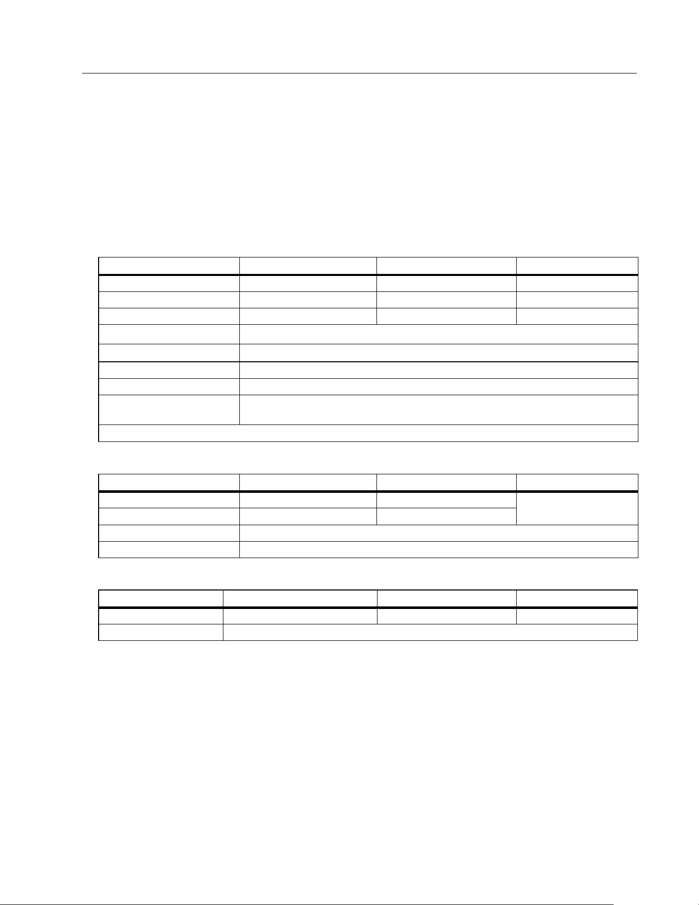
Tab le 1 . Func tions
Function Includes
Category 1 test
regime
Visual inspection checklist
Protective conductor resistance (R
LO
) measurement with a testing
current ≥200 mA (@2 Ω)
Polarity check with automatic display of the voltage polarity and
acoustic/visual warning for wrong polarity
Open-circuit voltage (V
OC
) measurement at the PV model/string with
up to 1000 V dc
Short-circuit (I
SC
) current measurement at the PV model/string with up
to 20 A dc
Insulating resistance (R
INS
) measurement with a testing voltage of
50 V, 100 V, 250 V, 500 V, 1000 V
Blocking diode measurement (V
BD
) with Method 1 and Method 2
(IEC 62446-1)
Bypass diode measurement of panel when covered or in darkness
Surge protection device (SPD)
Functional test
Power measurements on DC and AC side to check efficiency
Voltage DC/AC measurement
Current DC/AC measurement with clamp adapter i100
Functional test checklist
Category 2 test
regime
Solar panel string I-V curve test that includes Solar PV I-V curve
tracing and associated software for analysis, reporting, and
certification and includes I-V curve analysis and reporting features
Long-term monitoring of insulation errors (non-direct wet insulation test) and 24-hour
periodical measurement of R
INS
(adjustable time period)
Computer software - download, upload, review, analyze, and print test results
Communication with remote sensor (solar irradiation, inclination, temperature)
Communication with computer
1.888.610.7664 sales@GlobalTestSupply.com
Fluke-Direct.com

SMFT-1000
Users Manual
2
Safety Information
A Warning
identifies hazardous conditions and procedures that are dangerous to the user. A
Caution identifies conditions and procedures that can cause damage to the Product or the
equipment under test.
Specifications
Maximum voltage between any Terminal
and Earth Ground............................................ 1000 V dc
Maximum differential voltage between Red
and Blue terminals.......................................... 700 V ac
Size (L x W x H) ................................................. 10.0 cm x 25.0 cm x 12.5 cm (3.8 in x 9.8 in x 4.9 in)
Weight with batteries.................................... 1.4 kg (3.09 lb)
Battery................................................................. 6 x AA Alkaline IEC LR6
Battery Life........................................................ up to 1000 measurements
Fuse ...................................................................... F2: FF 630 mA, 1000 V, IR 30 kA
6.3 x 32 mm
F1: gPV DC 1000 V, 20 A, IR 30 kA (L/R= 2 ms), 10 mm x 38 mm
Te m p e r a t u re
Operating ......................................................... 0 °C to 50 °C (32 °F to 122 °F)
Storage ............................................................. -30 °C to 60 °C (-22 °F to 140 °F)
batteries removed
Relative Humidity............................................ up to 80 %
Altitude
Operating ......................................................... 2000 m
Storage ............................................................. 12 000 m
1.888.610.7664 sales@GlobalTestSupply.com
Fluke-Direct.com
Multifunction PV Analyzer
Specifications
3
Vibration ............................................................. MIL-PRF-28800F: Class 2
Ingress Protection .......................................... IEC 60529:IP40
Computer Interface........................................ IR (serial) and Bluetooth
Wireless connection compatibility.......... IRR2-BT
Accuracy
The accuracy specification is defined as ± (% reading + digit counts) at 23
o
C ± 5
o
C, ≤80 % RH.
The accuracy specification for 0
o
C to 18
o
C and 28
o
C to 50
o
C: 0.1 x (accuracy specification)
for each °C.
Protective Conductor Resistance R
LO
PV Model/PV String, Open-Circuit Voltage, (V
OC
)
PV Model/PV String, Short-Circuit Current, (I
S/C
)
Display Range Measurement Range Resolution Accuracy
0.00 Ω to 19.99 Ω 0.20 Ω to 19.99 Ω 0.01 Ω ± (2 % + 2 Digit)
20.0 Ω to 199.9 Ω 20.0 Ω to 199.9 Ω 0.1 Ω ± (2 % + 2 Digit)
200 Ω to 2000 Ω 200 Ω to 2000 Ω 1 Ω ± (5 % + 2 Digit)
Test current
≥200 mA (≤2 Ω + R
COMP
)
[1]
Te s t v o l t a g e
4 V
DC
to 10 V
DC
Polarity reversing Yes
Test lead zero (Rcomp) up to 3 Ω
Live circuit detection
Inhibits test if terminal voltage >50 V ac/dc (typical) detected prior to initiation
of test.
[1] The number of 200 mA @ 0.1 Ω continuity tests with a set of new batteries is >1000.
Display Range Measurement Range Resolution Accuracy
0.0 V to 99.9 V 5.0 V to 99.9 V 0.1 V
± (0.5 % + 2 Digit)
100 V to 1000 V 100 V to 1000 V 1 V
Polarity test Yes
Live circuit detection Inhibits test if terminal voltage >5 V ac detected prior to initiation of test.
Display Range Measurement Range Resolution Accuracy
0.0 A to 20.0 A 0.2 A to 20.0 A 0.1 A ± (1 % + 2 Digit)
Live circuit detection Inhibits test if terminal voltage >5 V ac (typical) detected prior to initiation of test.
1.888.610.7664 sales@GlobalTestSupply.com
Fluke-Direct.com
SMFT-1000
Users Manual
4
Insulation Resistance R
INS
Blocking Diode Check (V
BD
)
Surge Protection Devices (SPD)
True-rms AC V, DC V, AC A, DC A
The PV Analyzer measures both ac and dc signal components (voltage or current) and displays AC+DC
(rms) value combined. The display of ac or dc unit is dependent on if there is zero crossing of the signal.
AC/DC Voltage Measurement with 4 mm Test Sockets
Display Range Measurement Range Resolution Accuracy
0.00 MΩ to 99.99 MΩ 0.20 MΩ to 99.99 MΩ 0.01 MΩ ± (5 % + 5 Digit)
100.0 MΩ to 199.9 MΩ 100.0 MΩ to 199.9 MΩ 0.1 MΩ ± (10 % + 5 Digit)
200 MΩ to 999 MΩ 200 MΩ to 999 MΩ 1 MΩ ± (20 % + 5 Digit)
Test voltage @ no load
50 V / 100 V / 250 V up to 199.9 MΩ
1 V 0 % to + 20 %
500 V / 1000 V up to 999 MΩ
Te s t v o l t a g e @ ≥1 mA
250 V @ 250 kΩ
1 V 0 % to + 10 %500 V @ 500 kΩ
1000 V @ 1 MΩ
Te s t i n g c u rr e nt
Min. 1 mA (@ 250 kΩ / 500 kΩ / 1 MΩ)
Max. 1.5 mA (short circuit)
Live circuit detection
Inhibits test if terminal voltage >15 V ac (typical) detected prior to initiation of
test.
Maximum capacitive
load
Operable with up to 2 μF at 1MΩ
Note
The number of insulation tests with a new set of batteries is >900 at 1000V / 1 MΩ.
Display Range Measurement Range Resolution Accuracy
0.00 V dc to 6.00 V dc 0.50 V dc to 6.00 V dc 0.01 V dc ± (5 % + 10 Digit)
Live circuit detection
Inhibits test if terminal voltage >50 V ac/dc (typical) detected prior to initiation
of test.
Display Range Measurement Range Resolution Accuracy
0 V dc to 1000 V dc 50 V dc to 1000 V dc 1 V dc ± (10 % + 5 Digit)
Live circuit detection
Inhibits test if terminal voltage >50 V ac/dc (typical) detected prior to initiation
of test.
Display Range Measurement Range Resolution
Accuracy
(DC, AC 50 Hz/60 Hz)
0.0 V ac to 99.9 V ac 5.0 V ac to 99.9 V ac 0.1 V
± (2.5 % + 2 Digit)
100 V ac to 700 V ac 100 V ac to 700 V ac 1 V
0.0 V dc to 99.9 V dc 5.0 V dc to 99.9 V dc 0.1 V
100 V dc to 1000 V dc 100 V dc to 1000 V dc 1 V
Detection ac/dc Yes (Automatic)
Positive / negative polarity check Yes
1.888.610.7664 sales@GlobalTestSupply.com
Fluke-Direct.com

Multifunction PV Analyzer
Specifications
5
AC/DC Current with i100 Clamp
i100 Clamp Tolerances
AC/DC Power Measurement (with i100 Clamp)
Safety
SMFT-1000 ...................................................... IEC 61010-1 Pollution Degree 2
IEC 61010-2-034 CAT III 1000 V dc, CAT III 700 V ac
i100 Current Clamp....................................... IEC 61010-2-032, Type D (for insulated conductors), 1000 V
Accessories..................................................... IEC 61010-031
TL1000-MC4................................................ CAT III 1500 V, 20 A
TP1000 Remote Probe
with cap....................................................... CAT IV 600 V, CAT III 1000 V, 10 A
without cap ................................................ CAT II 1000 V, 10 A
TL1000 Test Leads..................................... CAT III 1000 V, 10 A
TL1000/30M Test Lead............................. CAT III 1000 V, CAT IV 600 V,
5 A (on reel) 10 A (fully extended)
TP74 Test Probes
with cap....................................................... CAT IV 600 V, CAT III 1000 V, 10 A
without cap ................................................ CAT II 1000 V, 10 A
AC285 Alligator Clips ................................ CAT III 1000 V, 10 A
Display Range Measurement Range Resolution
Accuracy
(DC, AC 50 Hz/60 Hz)
0.0 A dc to 100 A dc 1.0 A dc to 100 A dc
0.1 A
± (5 % + 2 Digit)
[1]
0.0 A ac to 100 A ac TRMS 1.0 A ac to 100 A ac TRMS
[1] i100 clamp tolerance not inclusive. See i100 Clamp Tolerances.
Measurement Range Output Signal
Accuracy
(DC, AC 50 Hz/60 Hz)
Maximum Hysteresis
1 A to 100 dc or ac <1 kHz 10 mV/A ac/dc ± (1.5 % + 0.5 A) ±0.4 A
Display Range Measurement Range Resolution
Accuracy
(DC, AC 50 Hz/60 Hz)
0.0 V ac to 700 V ac 5.0 V ac to 700 V ac
0.1 V ± (2.5 % + 2 Digit)
0.0 V dc to 1000 V dc 5.0 V dc to 1000 V dc
0.0 A ac/dc to 100 A ac/dc 1.0 A ac/dc to 100 A ac/dc 0.1 A ± (5 % + 6 Digit)
0 W/VA to 100 kW/kVA 5 W/VA to 100 kW/kVA 1 W / VA; 1 kW / kVA ± (7.5 % VI + 0.6 V + 0.2 I)
1.888.610.7664 sales@GlobalTestSupply.com
Fluke-Direct.com

SMFT-1000
Users Manual
6
Performance ..................................................... IEC 61557-1, IEC 61557-2, IEC 61557-4, IEC 61557-10
Electromagnetic Compatibility (EMC)
International .................................................... IEC 61326-1: Portable Electromagnetic Environment,
CISPR 11: Group 1, Class A
Group 1: Equipment has intentionally generated and/or uses conductively-coupled radio
frequency energy that is necessary for the internal function of the equipment itself.
Class A: Equipment is suitable for use in all establishments other than domestic and those directly
connected to a low-voltage power supply network that supplies buildings used for domestic
purposes. There may be potential difficulties in ensuring electromagnetic compatibility in other
environments due to conducted and radiated disturbances.
Caution: This equipment is not intended for use in residential environments and may not provide
adequate protection to radio reception in such environments.
Korea (KCC) ..................................................... Class A Equipment (Industrial Broadcasting & Communication
Equipment)
Class A: Equipment meets requirements for industrial electromagnetic wave equipment and the
seller or user should take notice of it. This equipment is intended for use in business
environments and not to be used in homes.
USA (FCC)......................................................... 47 CFR 15 subpart B.
Intentional Radiators: This device complies with part 15 of the FCC Rules. Operation is subject to
the following two conditions: (1) This device may not cause harmful interference, and (2) this
device must accept any interference received, including interference that may cause undesired
operation. (15.19). Changes or modifications not expressly approved by Fluke could void the
user's authority to operate the equipment. (15.21)
Wireless Radio Module
Frequency Range .......................................... 2.402 GHz to 2.480 GHz
Output Power.................................................. 8 dBm
SIMPLIFIED EU DECLARATION OF CONFORMITY
Hereby, Fluke declares that the radio equipment contained in this Product is in compliance with Directive
2014/53/EU. The full text of the EU declaration is available
1.888.610.7664 sales@GlobalTestSupply.com
Fluke-Direct.com
Multifunction PV Analyzer
Before you Start
7
Before you Start
This section is general information about the contents of the kit and how to familiarize yourself
with the controls and display of the PV Analyzer.
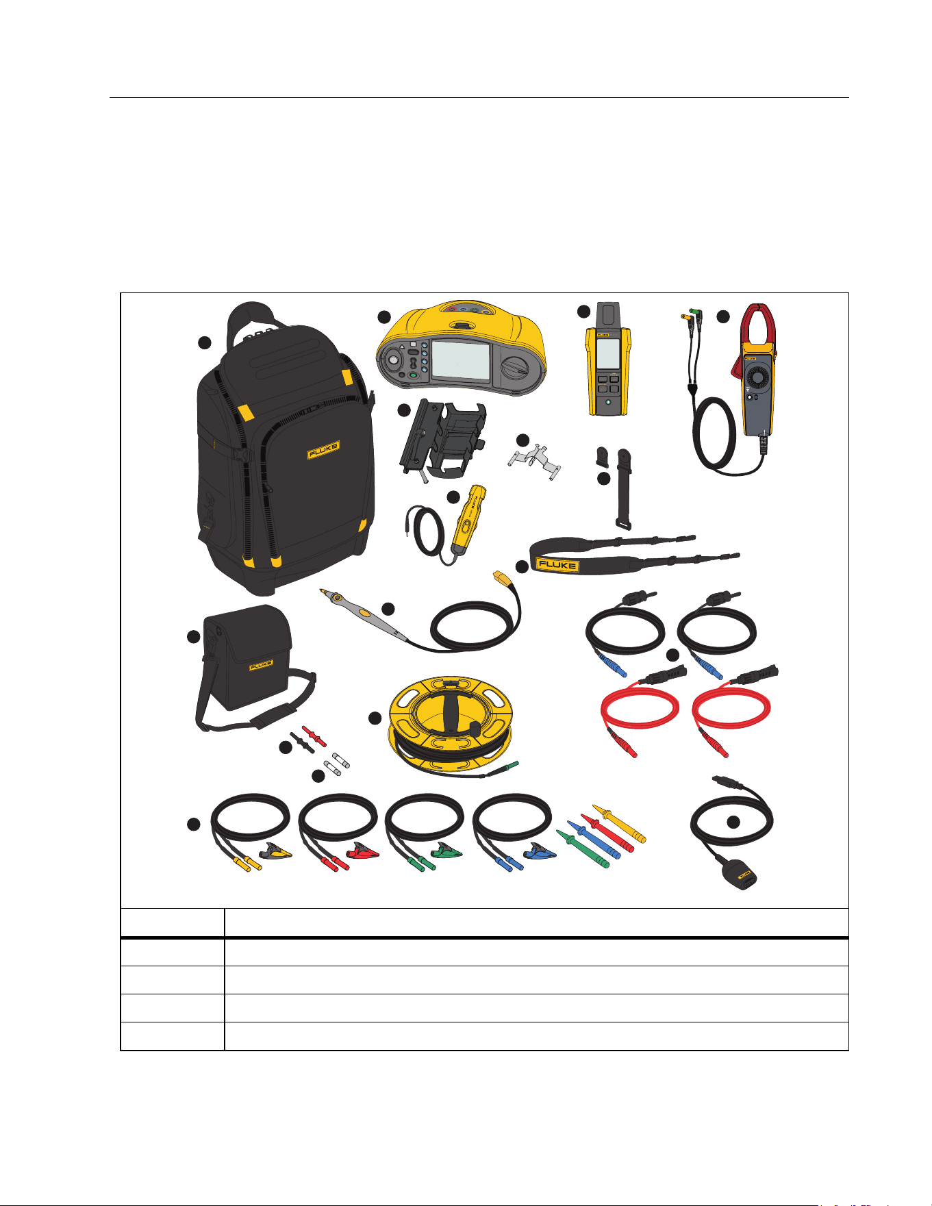
Kit Contents
Ta b l e 2 is a list of the contents in your kit.
Table 2. Kit Contents
Item Description
FlukePack30 Professional Tool Backpack
SMFT-1000 Multifunction PV Analyzer
IRR2-BT Wireless Solar Irradiance Meter
i100 AC/DC Current Clamp 100 A
1
2
3
5
6
4
7
9
8
10
11
12
13
14
15
16
17
i100
AC/DC SOLAR
CURRENT CLAMP
OUTPUT: 10mV/A
1.888.610.7664 sales@GlobalTestSupply.com
Fluke-Direct.com

SMFT-1000
Users Manual
8
It
em Des
cription
MB1-IRR Panel Mounting Bracket (for Irradiance Meter)
Zero Adapter
80PR-IRR External Temperature Probe
TPAK Magnet Set
Carry Strap (for SMFT-1000)
Carry Case (for Irradiance Meter)
TP1000 Test Probe with Remote Test Button
TL1000-MC4 Test Lead Set (Male and Female)
Coupler Set
Fuse Pack
TL1000/30M 30 m Test Lead on Reel
TL1000-KIT Test Lead Kit
IR Optical-to-USB Adapter Cable
not shown
6 x AA Alkaline IEC LR6 (for SMFT-1000, not installed)
4 x AA Alkaline IEC LR6 (for IRR2-BT, not installed)
2 x AA Alkaline IEC LR6 (for i100, not installed)
Table 2. Kit Contents (cont.)
1.888.610.7664 sales@GlobalTestSupply.com
Fluke-Direct.com
Multifunction PV Analyzer
Before you Start
9
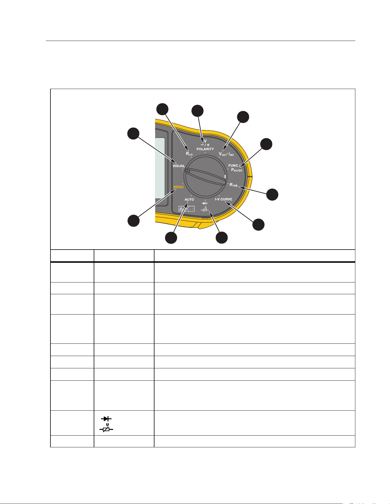
How to Use the Rotary Dial
Use the rotary dial to select the test type. See Ta b le 3 .
Table 3. Rotary Dial
Item Position Description
MENU
Memory for saved measurements, device settings, and Help
information
VISUAL Checklist for pre-inspection tests
R
LO
Continuity of equipotential bonding conductors and
lightning protection conductor wiring
V
-/+
POLARITY
Polarity test
V
OC
/I
SC
Open circuit voltage/short circuit current
FUNC./P
AC/DC
Power, voltage, current and functional checklist
R
INS
Insulation resistance
I-V CURVE
Graph of V
OC
tests for the maximum voltage and I
SC
tests for
the maximum current that a solar panel produces with
standard test conditions
Blocking/bypass Diode and Surge Protection Device (SPD)
AUTO Automated Testing Sequence
7
7
10
1
6
7
8
9
2
3
4
5
1.888.610.7664 sales@GlobalTestSupply.com
Fluke-Direct.com
SMFT-1000
Users Manual
10
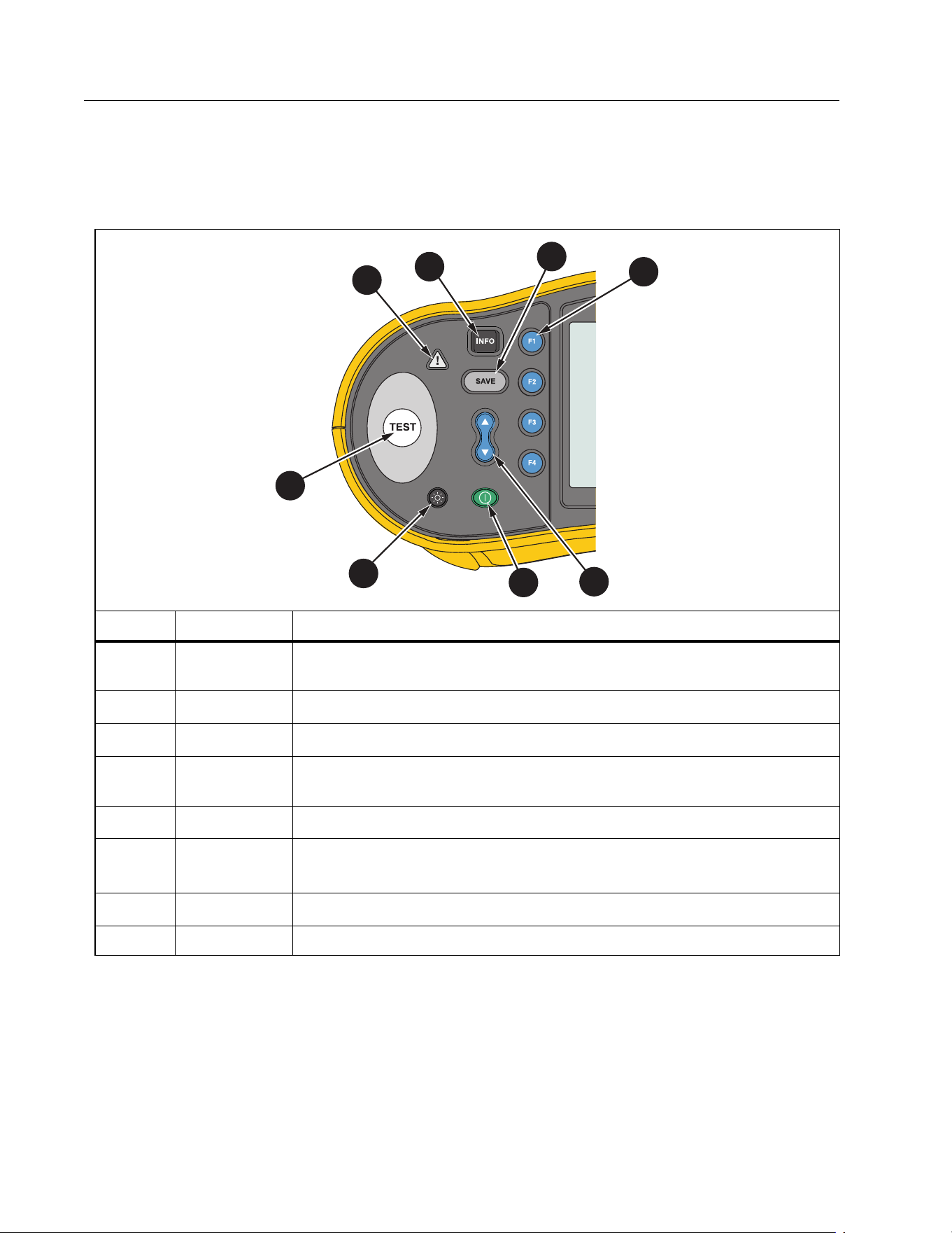
Buttons
Use the buttons to control operation of the PV Analyzer, select test results to view, and scroll
through selected test results. See Ta b l e 4 .
Tab le 4 . Push But to ns
Item Button Description
Shows illustrations and instructions for setup and test function
based on rotary dial position.
Save
Function selection
Use the up/down button to select features on the display. See
specific test instructions for more information.
Power on/off
Backlight on/off and intensity. Continuously push to cycle
through the intensity levels.
Start the selected test
W
Voltage warning
2
1
3
4
8
5
6
7
1.888.610.7664 sales@GlobalTestSupply.com
Fluke-Direct.com
Multifunction PV Analyzer
Before you Start
11
Info Button
The INFO button shows information about how to use each function of the PV Analyzer. As
the rotary dial moves to a function, push
to see connection drawings and tips about the
test function on the display. If a scroll bar shows on the right side of the display, use
to show
more information about the test function.
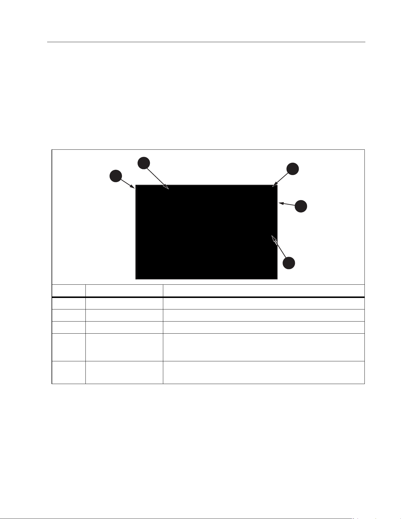
Display
Ta b l e 5 is an example of the display and components.
Tab le 5 . Di spl ay
Item Component Description
Navigation Shows the options for
Date/Time Stamp Date and time.
Battery Status Shows the status of battery power
Menu
Selected function is highlighted. Use
to change the
selection. Push
to open the options for the selection.
Menu Options
Shows the options available to setup or adjust. Push
to
exit the Menu Options.
1
2
3
4
5
1.888.610.7664 sales@GlobalTestSupply.com
Fluke-Direct.com
SMFT-1000
Users Manual
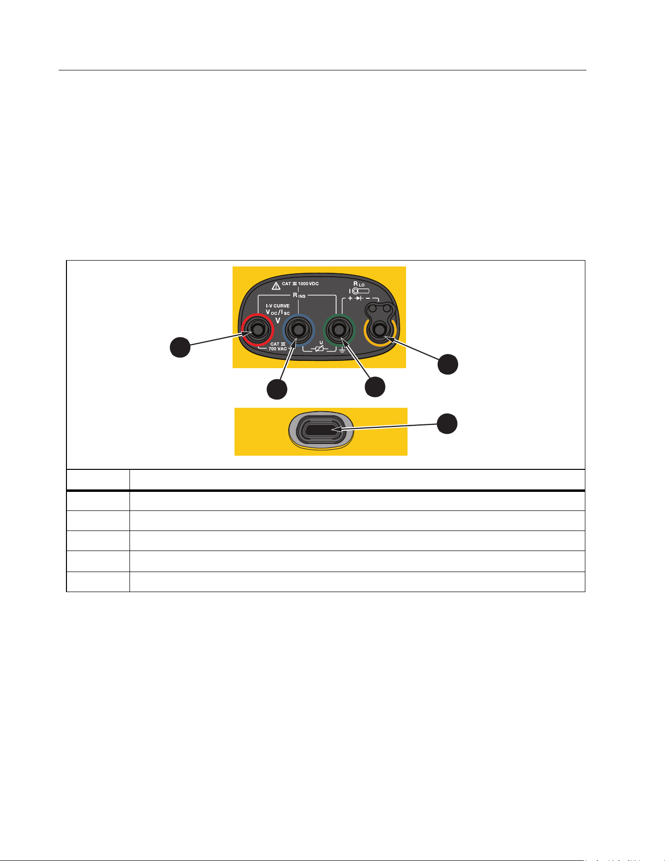
12
Terminals/Test Leads
Test leads are connected and stay in place (Keep the Leads) throughout the test. Ta b l e 6
shows the input terminals.
XW Warning
To prevent possible electrical shock, fire, or personal injury, do not use test leads
in CAT III or CAT IV environments without the protective cap installed. The
protective cap decreases the exposed probe metal to <4 mm. This decreases the
possibility of arc flash from short circuits.
The IR (infrared) port allows you to connect the Tester to a computer and download the test
data with TruTest™ Data Management Software documentation. With this software, you can
collect, organize, and display the test data. See Download Test Results for additional
information on using the IR port.
Tab le 6 . Term ina ls
Item Description
Red Socket (PV [+] V input)
Blue Socket (PV [-] COM input)
Green Socket (Earth)
Yellow Socket (R
PE
, Clamp input common)
IR Data Port
2
1
5
1
2
3
4
1.888.610.7664 sales@GlobalTestSupply.com
Fluke-Direct.com

Multifunction PV Analyzer
Before you Start
13
Error Messages
When the Analyzer detects error conditions, the display shows W and an error code. See
Ta b l e 7 . These error conditions disable or stop the test.
Tip: Push INFO for instructions about the error message.
Tab le 7 . Erro r Code s
Error
Code
Test Type Description
1.1
Pre-test
Automatic
Irregular voltage detected between inputs green and yellow
V ≥50.0 V
1.2
Pre-test
Automatic
Irregular voltage detected between inputs red and blue
V ≥1020 V, V
AB
Polarity: MINUS or AC (when V ≥5.0 V)
1.3
Pre-test
Automatic
Irregular voltage detected between inputs blue and yellow
V ≥30.0 V
1.4
Pre-test
Automatic
Short circuit current overload
I
SC
≥20.5 A
1.5
Pre-test
Automatic
Irregular voltage detected between inputs red and green (or blue and
green)
V ≥50.0 V
1.6
Pre-test
Automatic
Irregular voltage detected between inputs red and blue
V ≥1020 V DC, ≥720 V AC, MINUS (when V ≥5.0 V)
1.7
Pre-test
Automatic
Irregular voltage detected between inputs green and yellow
V ≥720.0 V
2.1
Automatic
Te s t
Overheating (over-temperature)
3.1
Automatic
Te s t
Memory overload
4.1
Te s t
Post-test
Fuse F1 Failed
Internal test indicates that the safety fuse (20 A) is open. F1 fuse
replacement must be done by a qualified technician.
4.2
Te s t
Post-test
Fuse F2 Failed
Internal test indicates that the safety fuse (0.63 A) is open and needs
to be replaced to do this measurement. See Fuse Replacement.
4.3
Te s t
Post-test
Fuse F1 and F2 Failed
Internal test indicates that both safety fuses (20 A and 0.63 A) are
open and need to be replaced to do this measurement. F1 fuse
replacement must be done by a qualified technician.
1.888.610.7664 sales@GlobalTestSupply.com
Fluke-Direct.com
SMFT-1000
Users Manual
14
How to Zero the Test Leads
XW Warning
To prevent possible electrical shock, fire, or personal injury, do not use in CAT III
or CAT IV environments without the protective cap installed. The protective cap
decreases the exposed probe metal to <4 mm. This decreases the possibility of
arc flash from short circuits.
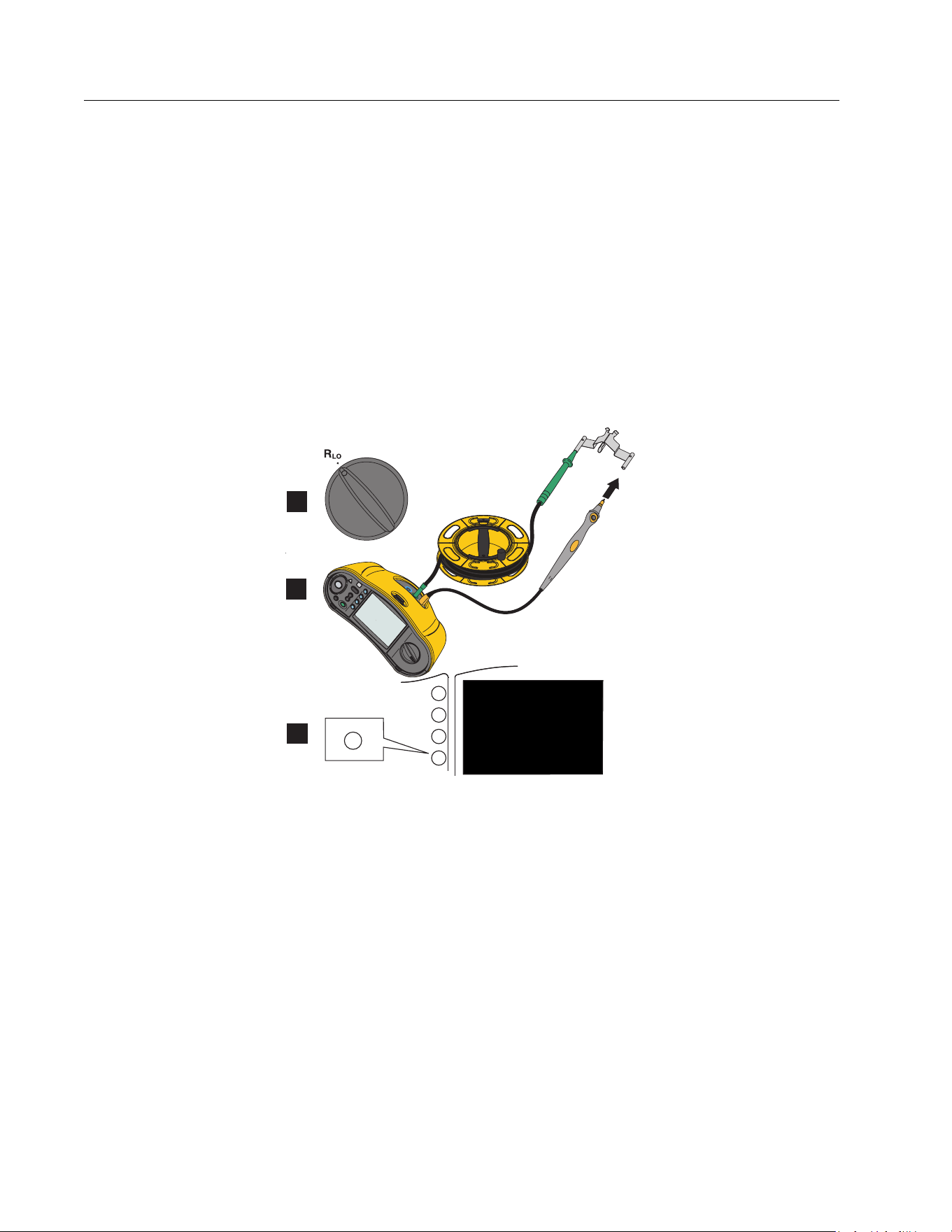
When you measure the Continuity (R
LO
) of equipotential bonding conductors and lightning
protection conductor wiring, the test leads have a small amount of inherent resistance that can
affect a measurement. Before you do a continuity test, use the zero adapter to compensate
for, or zero, the test leads. See Figure 1.
Figure 1. Zero Adapter Configuration
F2
F3
F4
F1
F4
1
2
3
1.888.610.7664 sales@GlobalTestSupply.com
Fluke-Direct.com

Multifunction PV Analyzer
Te s t S e tu p
15
Te s t S e t u p
Use this kit for safety and performance analysis of solar systems according to IEC 62446-1.
The kit contains the SMFT-1000 PV Analyzer (PV Analyzer) and the IRR2-BT Irradiance Meter
(Irradiance Meter).
The PV Analyzer provides safety and performance measurements of the solar system.
The Irradiance Meter provides auxiliary data of sun irradiance and solar panel temperature.
This data complements the IV Curve Solar Panel performance measurements on the PV
Analyzer. The IRR2-BT sends the data to the PV Analyzer wirelessly. If wireless connection is
interrupted for any reason, the Irradiance Meter automatically records the data that is later
transferred when the connection is reestablished. Both devices have synchronized clocks to
properly match the data.
Note
Before taking IV Curve performance measurements, synchronize the PV Analyzer and
Irradiance Meter via wireless connection. See Pair PV Analyzer to the Irradiance Meter.
To power on the PV Analyzer:
1. Push
for 1 s. to turn on the PV Analyzer.
The displays shows a startup screen with the firmware version.
2. Push
for 2 s. to turn off the PV Analyzer.
Pair PV Analyzer to the Irradiance Meter
For first time use, you must pair the PV Analyzer Analyzer with the Irradiance Meter:
1. Turn on the PV Analyzer and the Irradiance Meter.
2. Make sure the PV Analyzer and the Irradiance Meter are within the wireless range (<50 m) of
each other.
3. Turn the rotary dial to MENU.
4. Use
to highlight Device Settings.
5. Push
to open the Device Settings menu.
6. Use
to highlight Irradiance Meter Pairing.
7. Push
.
8. Follow the on-screen directions on the PV Analyzer to pair the devices.
shows on the PV Analyzer display to indicate that the PV Analyzer and Irradiance Meter
are connected.
After the initial setup, the PV Analyzer pairs with the IRR2-BT when you turn on both
devices and are within the wireless range (<50 m).
1.888.610.7664 sales@GlobalTestSupply.com
Fluke-Direct.com

SMFT-1000
Users Manual
16
For IV Curve measurements, synchronize the PV Analyzer with the IRR2-BT at the start of the
work day:
1. Turn on the PV Analyzer and the Irradiance Meter.
2. Make sure the PV Analyzer and the Irradiance Meter are within the wireless range (<50 m) of
each other.
3. On the PV Analyzer, turn the rotary switch to I-V CURVE.
4. Press
.
5. Follow the on-screen directions on the PV Analyzer to synchronize both devices.
shows on the PV Analyzer display to indicate that the PV Analyzer and the Irradiance
Meter are connected.
During synchronization, the PV Analyzer matches all the data from the Irradiance Meter to the
recordings on the PV Analyzer from the previous sessions. The real-time clocks on both
devices synchronize and the Irradiance Meter clears its memory. The Irradiance Meter
continuously records data for up to 17 hours.
An option to manually enter irradiance and temperature measurements is available. For more
information, see I-V Curve Test.
Note
If the Irradiance Meter is installed on the panel, move the PV Analyzer within the
wireless range.
IEC 62446-1 Category 1 Tests
Visual Inspection
IEC regulations require a visual inspection of the Solar System. The PV Analyzer provides a
checklist with each task and then records and saves the results of the visual inspection to the
internal memory. All results can be downloaded to the PC software and used for final reports.
To d o a vi su a l i n s p e c t io n :
1. Turn on the PV Analyzer.
2. Turn the rotary switch to VISUAL and follow the on-screen prompts.
3. If a scroll bar shows on the right side of the display, use
to show more information about
the checklist.
4. Use
or to select a result.
5. Push
to store results to memory.
A confirmation message shows on the display.
1.888.610.7664 sales@GlobalTestSupply.com
Fluke-Direct.com

Multifunction PV Analyzer
Te s t S e tu p
17
Continuity of Protective Earthing and Equipotential Bonding Conductors
For accurate measurements, always compensate the resistance of the test leads before you
make measurements:
1. Turn on the PV Analyzer.
2. Turn the rotary switch to
.
3. Zero (short) the green lead and yellow lead.
4. Push
.
For more information, see Figure 1.
5. Follow the on-screen prompts.
6. To assign Pass or Failed status, set the regulatory limits for the measurements.
Note
You cannot change the limits after the measurement is taken. If you change the limit,
you must repeat the measurement.
Set Limits
The regulatory limit is based on the length of the cable used in the test.
To s et :
1. Turn on the PV Analyzer.
2. Turn the rotary switch to
.
3. Use
or to highlight an option.
4. Push
to edit the option.
The Manual Entry screen shows on the display.
5. Push
to open the Adjustment menu.
6. Use
to change the value.
7. Adjust the Cross Section and Material options as required.
8. Push
to toggle between the Manual Entry screen and Auto Calculate limit.
9. Push
to save the calculation and return to the Measurement screen.
1.888.610.7664 sales@GlobalTestSupply.com
Fluke-Direct.com

SMFT-1000
Users Manual
18
Resistance Test (R
LO
)
The PV Analyzer measures protective conductor resistance () with a test current ≥200 mA
(@2 Ω) for:
Earthing and Equipotential Bonding Conductors to IEC 62446-1 Clause 6.1
Lightning Protection System (LPS)
Grounding System
Resistance of Earthing and Equipotential Bonding Conductors
To measure the resistance of earthing and equipotential bonding conductors:
1. Turn the rotary switch to
.
2. Use
to select Equipotential Bonding.
3. Push
to select One Shot (default mode) and follow the on-screen prompts.
4. Connect the green test lead to the central PE connector / ground.
5. Connect the yellow test lead to the measurement point.
This could be the metal frame of the module or the rails of the solar mounting system.
6. Push
ether on the PV Analyzer or on the Remote Probe.
In this mode the PV Analyzer does a short measurement (R
LO
+) followed by a second short
measurement (R
LO
-) with reversed polarity.
The PV Analyzer shows both results when the measurement is complete and selects the
highest measurement (worst) as the main result. Based on the chosen limit, all three results
are determined as PASS or FAIL.
The PV Analyzer also shows the value of the test current applied during the resistance test
(I
RLO
).
Lightning Protection Conductor Wiring
To measure resistance in Lightning Protection System (LPS):
1. Turn the rotary switch to the R
LO
position.
2. Use
to select Lightning Protection Conductor.
3. Push
to select One Shot (default mode) and follow the on-screen prompts.
In this mode the PV Analyzer does a short measurement (R
LO+
) followed by a second short
measurement (R
LO-
) with reversed polarity. The PV Analyzer shows both results when the
measurement is complete and selects the highest measurement (worst) as the main result.
Based on the chosen limit, all three results are determined as PASS or FAIL.
1.888.610.7664 sales@GlobalTestSupply.com
Fluke-Direct.com

Multifunction PV Analyzer
Te s t S e tu p
19
Grounding System
To troubleshoot the grounding system with the R
LO
Continuous Measurement method:
1. Push
for R+ Positive or for R- Negative and follow the on-screen prompts.
Polarity Test
The polarity test verifies to IEC 62446-1 Clause 6.2 that the positive and negative wires are
correctly connected to the solar system combiner box, inverter, or switch gear.
XW Warning
To prevent personal injury or damage to the system, all connections must use the
correct polarity.
To t es t p o l a ri t y :
1. Turn the rotary switch to -/+ POLARITY.
2. Connect the red test lead to the positive connector of the PV string and the blue test lead
to the negative connector of the PV string.
Tip: Push
to see the connection diagram.
3. Follow the on-screen prompts.
The upper display shows the actual voltage connected to the test leads. For voltages >5 V
the PV Analyzer determines the measurements as
or . All positive voltage show as
PASS and all negative voltages as FAIL.
If ac voltage is detected, a warning shows on the display.
PV String Combiner Box
This test procedure verifies to IEC 62446-1 Clause 6.3. Do this test before any string fuses or
connectors are connected for the first time:
Connect all negative fuses or connectors so strings share a common negative bus.
Do not connect any positive fuses or connectors.
Measure the open circuit voltage of the first string, positive (red test lead) to negative (blue
test lead), and assure that it is an expected value.
Continue with subsequent strings, positive to negative, and assure that it is the expected
value and do not differ more than ±15 V from the strings previously measured.
To test string fuses:
1. Turn the rotary switch to -/+ POLARITY.
2. Push
to see the connection diagram.
3. Follow the on-screen prompts.
1.888.610.7664 sales@GlobalTestSupply.com
Fluke-Direct.com

SMFT-1000
Users Manual
20
PV String
Open circuit voltage measurement and circuit current test (short circuit test or operational).
Open circuit voltage measurement (V
OC
)
Open circuit voltage (V
OC
) measurement to IEC 62446-1 Clause 6.4. This test checks that
module strings are correctly wired and that the expected number of modules are connected in
series within the string. For strings connected in series, the measured voltage should be a sum
of the voltages of individual solar panels in the string. This test can also be also used to verify
open voltage of the individual panel.
Circuit current test - short circuit test (I
SC
)
The PV string circuit current test to IEC 62446-1 Clause 6.5.2 is a short-current measurement
test to verify the correct operational characteristics of the system and that no major faults are
within the PV array wiring. These tests are not to be taken as a measure of module / array
performance. Compare the results of the short-current measurement with solar panel
specifications. The PV Analyzer does all calculations automatically if solar panel specifications
are linked and Irradiance/Temperature measurements are transferred from the Irradiance
Meter.
Operational test method
Alternative test method for I
SC
(see IEC 62446-1 Clause 6.5.3).
To t es t:
1. Download the panel specifications.
2. Select PV model.
3. Enter the number of modules for each string.
4. Install Irradiance Meter at the solar panel to test.
5. Turn the rotary switch to V
OC
/I
SC
.
6. Connect the red test lead to positive connector of string and the blue test lead to negative
connector of string.
Tip: Push
to see connection diagram.
7. Follow the on-screen prompts.
The PV Analyzer determines the results for open circuit voltage measurement and short
circuit test as PASS or FAIL based on the chosen PV model panel data and number of
modules.
1.888.610.7664 sales@GlobalTestSupply.com
Fluke-Direct.com

Multifunction PV Analyzer
Te s t S e tu p
21
Voltage/Current Test (V
OC
/I
SC
)
The V
OC
is a test to IEC 62446-1 Clause 6.4 for the maximum voltage that the solar panel
produces in standard test conditions. The I
SC
is a test to IEC 62446-1 Clause 6.5.2 for the
maximum current that the solar panel produces in standard test conditions.
To t es t :
1. Install the Irradiance Meter at the solar panel to test.
2. Turn the rotary switch on the PV Analyzer to the V
OC
/I
SC
position.
3. Set the limit for V
OC
based on data from Irradiance Meter and PV model.
STC calculation limits: calculated from irradiance and nominal values.
4. Set the limit for I
SC
based on data from Irradiance Meter and PV model.
STC calculation limits: calculated from irradiance and nominal values.
Irr & Tcell data from the Irradiance Meter shows on the display.
5. Connect the red test lead to positive connector of string and the blue test lead to negative
connector of string.
Tip: Push
to see a connection diagram.
The V
OC
measurement shows on the display after you connect the test leads.
Note
If the PV Analyzer detects reverse polarity, you will hear an audible beep and the
display shows a warning for a failed test due to a negative measurement.
6. Push
to start the I
SC
measurement.
The V
OC
and I
SC
results show on the display with a Pass/Fail icon based on the limit from the
Irradiance Meter.
7. Push
to save the results to memory.
A confirmation message with ID number shows on the display and then returns to the test
screen.
1.888.610.7664 sales@GlobalTestSupply.com
Fluke-Direct.com

SMFT-1000
Users Manual
22
Select PV Model
When the Irradiance Meter is not connected, no limits are available and no irradiance or
temperature data shows on the display.
To take a measurement:
1. Connect the test leads from the PV Analyzer to the solar panel.
Tip: Push
to see a connection diagram.
The V
OC
measurement shows on the display after you connect the test leads. The Pass/Fail
icons do not show in this configuration.
2. Push
to start the I
SC
measurement.
The V
OC
and I
SC
results show on the display.
3. Push
to save the results to memory.
A confirmation message with ID number shows on the display and then returns to the test
screen.
Paired with Irradiance Meter Only
When the Irradiance Meter is connected and a PV model is not selected, no limits are available.
The irradiance and temperature data from the Irradiance Meter shows on the display.
To take a measurement:
1. Connect the test leads from the PV Analyzer to the solar panel. The V
OC
measurement
automatically shows on the display.
Tip: Push
to see a connection diagram.
The V
OC
measurement shows on the display after you connect the test leads. Irr & Tcell
data from the Irradiance Meter shows on the display. The Pass/Fail icons do not show in
this configuration.
2. Push
to start the I
SC
measurement.
The V
OC
and I
SC
results show on the display.
3. Push
to save the results to memory.
A confirmation message with ID number shows on the display and then returns to the test
screen.
1.888.610.7664 sales@GlobalTestSupply.com
Fluke-Direct.com

Multifunction PV Analyzer
Te s t S e tu p
23
Quick V
OC
/I
SC
Measurement
Yo u c a n ta ke a q u ic k V
OC
/I
SC
measurement without connecting the Irradiance Meter or
PV model. Pass/Fail limits or Irradiance data do not show with this type of measurement.
To take a measurement:
1. Turn the rotary switch on the PV Analyzer to V
OC
/I
SC
.
2. Connect the test leads to the solar panel. The V
OC
measurement automatically shows on
the display.
Tip: Push
to see a connection diagram.
Voltage symbol is on when voltage is ≥50 V.
3. Push
to start the I
SC
measurement.
The V
OC
and I
SC
results show on the display. The Pass/Fail icons do not show in this
configuration.
4. Push
to save the results to memory.
A confirmation message with ID number shows on the display and then returns to the test
screen.
V
OC
/Operational Current Measurement
Operational current as alternative method for I
SC
as required by IEC 62446-1 Clause 6.5.3.
To take a measurement:
1. Connect the PV string to the inverter and switch the system to on and normal operation
mode (inverter must be at maximum power point).
It is useful to connect two Y-connectors in between so you can measure the string voltage
in parallel.
2. Turn the rotary switch to V
OC
/I
SC
.
3. Connect the test leads to the solar panel.
The V
OC
measurement automatically shows on the display.
Tip: Push
to see a connection diagram.
1.888.610.7664 sales@GlobalTestSupply.com
Fluke-Direct.com

SMFT-1000
Users Manual
24
4. Push
to start the V
OC
measurement.
The V
OC
measurement shows on the display. If the PV model is selected and the Irradiance
Meter is connected, the Pass/Fail icons show on the display. The Measure V
OC
instructions
are grayed-out with a checkmark to indicate that the measurement is done. The Measure
Operational Current instructions become enabled/brighter.
5. Connect the Clamp and make sure the current flow/polarity matches with the arrow on the
Clamp.
Tip: Push
to see a connection diagram.
6. Push
to start the Operational Current measurement.
Power AC/DC and Function Tests
Tests the power output from the PV system to make sure that the dc power produced by the
panels is inverted properly into ac power as required by IEC 62446-1 Clause 6.6.
Single Phase Inverter Performance Check
Measure the dc power, then ac power, then compare efficiency.
To make a dc measurement:
1. Turn the rotary switch on the PV Analyzer to FUNC./P
AC/DC
.
The display shows power in the blank state and is ready to compare the dc and ac
measurements.
2. Push
to set the Efficiency Factor Limit.
3. Connect the PV string to the inverter and switch the system to on and normal operation
mode (the inverter has to be at maximum power point).
4. Connect the red test lead in parallel to the positive connector of the PV string and the blue
test lead in parallel to the negative connector of the PV string to the solar panel.
5. Connect the Clamp and make sure the current flow/polarity matches with the arrow on the
Clamp.
Tip: Push
to see a connection diagram.
6. Push
.
7. Push
to hold the dc measurements.
The blue column header indicates that the dc measurements are on hold.
1.888.610.7664 sales@GlobalTestSupply.com
Fluke-Direct.com

Multifunction PV Analyzer
Te s t S e tu p
25
8. Push
to clear or cancel the dc measurement column and return to the blank state.
To make an ac measurement:
1. Connect the test leads to the ac output of the inverter.
2. Connect the Clamp.
Tip: Push
to see a connection diagram.
3. Push
.
4. Push
to hold the ac measurements.
The blue column header indicates that the ac measurements are on hold.
The display shows the Efficiency Factor ratio with a Pass or Fail icon.
5. Push
to save the results to memory.
A confirmation message with ID number shows on the display and then returns to the test
screen.
3-Phase Inverter Performance Check
Measure the dc power, then ac power (L1 + L2 + L3), then compare efficiency.
To m a ke a m e a s u re me nt :
1. Turn the rotary switch on the PV Analyzer to FUNC./P
AC/DC
.
The display shows power in the blank state and is ready to check the 3-phase power.
2. Push
to toggle between Single Phase and 3 Phase power.
3. Push
to set the Efficiency Factor Limit.
4. Push
.
5. Push
to hold the dc measurements.
The blue column header indicates that the dc measurements are on hold.
6. Push
.
7. Push
to hold the ac-L1 measurements.
The blue column header indicates that the ac-L1 measurements are on hold.
8. Push
.
9. Push
to hold the ac-L2 measurements.
The blue column header indicates that the ac-L2 measurements are on hold.
1.888.610.7664 sales@GlobalTestSupply.com
Fluke-Direct.com

SMFT-1000
Users Manual
26
10. Push
.
11. Push
to hold the ac-L3 measurements.
The blue column header indicates that the ac-L3 measurements are on hold.
The display shows the Efficiency Factor ratio with a Pass or Fail icon.
12. Push
to save the results to memory.
A confirmation message with ID number shows on the display and then returns to the test
screen.
AC/DC Voltage Measurement
Single-shot voltage measurement that automatically detects ac or dc power.
To make a measurement:
1. Turn the rotary switch on the PV Analyzer to FUNC./P
AC/DC
.
2. Push
to measure the voltage.
The dashes on the display indicate that no leads are connected to the PV Analyzer.
3. Connect the test leads to the circuit under test.
Tip: Push
to see a connection diagram.
The PV Analyzer automatically detects if the measurement is ac or dc voltage.
4. Push
to hold the measurement.
The measurement is on hold.
5. Push
to save the results to memory.
A confirmation message with ID number shows on the display and then returns to the test
screen.
AC/DC Current Measurement
Single-shot current measurement that automatically detects ac or dc power.
To make a measurement:
1. Turn the rotary switch on the PV Analyzer to FUNC./P
AC/DC
.
2. Toggle
to measure the current.
The
button toggles the selection between a voltage or current measurement. The
dashes on the display indicate that no leads are connected to the PV Analyzer.
1.888.610.7664 sales@GlobalTestSupply.com
Fluke-Direct.com

Multifunction PV Analyzer
Te s t S e tu p
27
3. Connect the clamp to the circuit under test.
Tip: Push
to see a connection diagram.
The PV Analyzer automatically detects if the measurement is ac or dc current.
4. Push
to hold the measurement.
The measurement is on hold.
5. Push
to save the results to memory.
A confirmation message with ID number shows on the display and then returns to the test
screen.
Functional Tests
Checklist of functional tests.
To t es t :
1. Turn the rotary switch on the PV Analyzer to FUNC./P
AC/DC
.
2. Push
to start to record the results of the functional tests.
3. Use
to highlight the different checklist items.
4. Push
and to select pass, fail, or N/A for the highlighted row.
5. Push
(Back) to return to the Power test.
If any check boxes are filled in, then
is available. All results show on the display until you
clear for a new session regardless of power on/off or different day.
6. Push
to save the results to memory.
A confirmation message with ID number shows on the display and then returns to the test
screen.
1.888.610.7664 sales@GlobalTestSupply.com
Fluke-Direct.com

SMFT-1000
Users Manual
28
Insulation Resistance Test (R
INS
)
The R
INS
Mode is a test for the resistance of the insulation between the ground and the PV
Array as required by IEC 62446-1 Clause 6.7. Repeat this test, as a minimum, for each PV array
or sub-array. You can also test individual strings if required.
Test Method 1 (Keep the Leads)
This test is between the PV Array negative and earth followed by a test between the PV Array
positive and earth. For this test, the connections do not change (Keep the Leads option).
To t es t:
1. Turn the rotary switch on the PV Analyzer to R
INS
.
2. Connect the test leads to the solar panel.
Tip: Push
to see a connection diagram.
If ground-point and frames are bonded to earth point on site:
a. Connect the green test lead to ground.
b. Connect the red test lead to positive terminal on the PV Array.
c. Connect the blue test lead to negative terminal on the PV Array.
OR
If ground-point and frames are not bonded to earth point on site (protection class II of
installation):
a. Connect the green test lead to PV Array frame.
b. Connect the red test lead to positive terminal on the PV Array.
c. Connect the blue test lead to negative terminal on the PV Array.
3. Use the
to select the nominal test voltage (V
N
selection=50/100/250/500/1000 V).
This value will trigger the limit values.
4. After leads are configured, push
>1 s. to start the R
INS
(1) measurement.
The dashes blink during the measurement calculation and then the test results show on the
display:
R
INS
: lowest number of R
INS
+ or R
INS
-
R
INS
+: insulation resistance PV+ to ground
R
INS
-: insulation resistance PV- to ground
V
INS
+: applied test voltage during the insulation test (PV+ to ground)
V
INS
-: applied test voltage during the insulation test (PV- to ground)
1.888.610.7664 sales@GlobalTestSupply.com
Fluke-Direct.com

Multifunction PV Analyzer
Te s t S e tu p
29
Passed:
and a short beep noise indicates the test passed when the results are greater
than the preset limits.
Failed:
and multiple beeps indicates the test failed when the results are less than the
preset limits.
5. Push
to save the results to memory.
A confirmation message with ID number shows on the display and then returns to the test
screen.
Note
If the resistance is outside an acceptable threshold from the R
INS
test (1 or 2), use the
Continuous test to find the exact location on the insulation where the resistance is
failing. See Continuous Measurement.
Test Method 2 (Default)
The default Test Method 2 is a test between earth and the short-circuited array for a positive
and then negative measurement. This method also uses the Keep the Leads option.
1. Turn the rotary switch on the PV Analyzer to R
INS
.
2. Use
to select the nominal test voltage (V
N
selection=50/100/250/500/1000 V).
This value will trigger the limit setting.
3. Connect the test leads to the PV Array.
Tip: Push
to see a connection diagram.
If ground-point and frames are bonded to earth point on site:
a. Connect the green test lead from green socket to ground.
b. Connect the red test lead from red socket to positive terminal on the PV Array.
c. Connect the blue test lead from blue socket to negative terminal on the PV Array.
OR
If ground-point and frames are not bonded to earth point on site (protection class II of
installation):
a. Connect the green test lead from green socket to PV Array frame.
b. Connect the red test lead from red socket to positive terminal on the PV Array.
c. Connect the blue test lead from blue socket to negative terminal on the PV Array.
1.888.610.7664 sales@GlobalTestSupply.com
Fluke-Direct.com

SMFT-1000
Users Manual
30
4. After leads are configured, push
to start the R
INS
(2) measurement.
Note
The high voltage icon and dashes show during the measurement.
When complete the test results show on the display:
R
INS
(2): measured insulation resistance
V
INS
: applied test voltage during the insulation test
Passed:
and a short beep noise indicates the test passed when the results are greater
than the preset limits.
Failed:
and multiple beeps indicates the test failed when the results are less than the
preset limits.
5. Push
to save the results to memory.
A confirmation message with ID number shows on the display and then returns to the test
screen.
Note
If the resistance is outside an acceptable threshold from the R
INS
test (1 or 2), use the
Continuous test to find the exact location on the insulation where the resistance is
failing. See Continuous Measurement.
Continuous Measurement
You can measure R
INS
between any two measurement points in the PV system. This
measurement helps to troubleshoot insulation faults on the wiring cables. Fluke recommends
that you remove the solar modules for this test as they can influence the result.
To m e a s u re :
1. Turn the rotary switch on the PV Analyzer to R
INS
.
2. Push
to enter the R
INS
Continuous mode.
3. Use
to select the nominal test voltage (V
N
selection=50/100/250/500/1000 V).
This value will trigger the limit values.
Tip: Push
to see a connection diagram.
4. After you connect the leads, push
>1 s. to start the R
INS
Continuous measurement.
1.888.610.7664 sales@GlobalTestSupply.com
Fluke-Direct.com

Multifunction PV Analyzer
Te s t S e tu p
31
The dashes show during the measurement calculation and then the test results show on
the display:
Live Results: measurement results refresh every second.
Green check mark appears when result is under the limit.
5. Push
>1 s. at any time to pause and hold the measurement on the screen.
6. Push
>1 s. again to resume measurement.
7. Move test leads up and down the cable until you find the resistance issue:
shows on the display next to measured resistance that is below the limit.
multiple beeps indicate the test failed.
8. Push
to save the results to memory.
A confirmation message with ID number shows on the display and then returns to the test
screen.
OR
9. Connect to the next test point (not necessary to clear if you do not save) or proceed to the
next test.
Wet Insulation Resistance Test
The wet insulation resistance test meets IEC 62446-1 Clause 8.3 requirements and is best
used as a fault-finding exercise. This resistance test evaluates the PV Array electrical
insulation in wet operating conditions. The test simulates rain or dew on the array and wiring
and then verifies that moisture will not enter active portions of the array electrical circuitry
where it may enhance corrosion, cause ground faults, or pose an electrical safety hazard to
personnel or equipment. This test is especially effective for finding above ground defects such
as wiring damage, inadequately secured junction box covers, and other similar installation
issues. It also may be used to detect manufacturing and design flaws including polymer
substrate punctures, cracked junction boxes, inadequately sealed diode cases, and improper
(indoor rated) connectors.
A wet insulation test would be implemented when the results of a dry test are questionable or
where insulation faults due to installation or manufacturing defects are suspected.
The test is applied to a whole array or on larger systems to select parts such as components or
sub-sections of the array. Where only parts of the array are being tested, these are selected
due to a known or suspected problem identified during other tests. In some circumstances, the
wet insulation test may be requested on a sample portion of the array.
Use the same test sequence in Test Method 1 (Keep the Leads) or Te s t M e th o d 2 ( De fa ul t ) .
1.888.610.7664 sales@GlobalTestSupply.com
Fluke-Direct.com

SMFT-1000
Users Manual
32
I-V Curve Test
V
OC
is a test for the maximum voltage that the solar panel can produce under standard test
conditions as required by IEC 62446-1 Clause 7.2. I
SC
is a test for the maximum current that
the solar panels can produce under standard test conditions.
To m e a s u re :
1. Turn the rotary switch on the PV Analyzer to I-V Curve.
The I-V Curve Table shows on the display and indicates if the PV Analyzer is connected to
the Irradiance Meter or PV model.
If not connected:
a. Push
IRR Meter to pair the Irradiance Meter with the PV Analyzer. For more
information, see Pair PV Analyzer to the Irradiance Meter.
b. Push
PV Model to select the PV model from the database.
When connected, the I-V Curve Table shows:
Irradiance live reading from the Irradiance Meter
Cell Temperature live reading from the Irradiance Meter
Nominal Values based on the PV model
2. Push
to view the I-V Curve Graph.
The I-V Curve Graph shows:
Nominal Curve based on data from the PV model
Area Curve shows the range of the min-to-max values of the Nominal Curve based on
the Nominal values
±5 % (Pass Criteria = 5 %)
3. Connect the red test lead to the positive connector of the PV Array and the blue test lead
to the negative connector of the PV Array.
Tip: Push
to see a connection diagram.
4. Attach the Irradiance Meter to the panel with the bracket.
5. Push
to start the measurement and create an I-V curve.
The display shows a progress bar.
6. Push
to cancel the test.
1.888.610.7664 sales@GlobalTestSupply.com
Fluke-Direct.com

Multifunction PV Analyzer
Te s t S e tu p
33
Note
A warning shows on the display if the PV Analyzer detects reverse polarity at the start
of the test. Push
to see a connection diagram.
When the test is complete, the test results show in the I-V Curve Table:
STC column shows values
Pass/Fail indicators show for each row
MEAS (measured) column shows values
7. Push
to view a Graph display the of measured curve and STC curve on top of the NOM
area curve.
8. Use
to toggle between the two table and graph views:
Advanced Table View with an additional column that shows the measured values
Advanced Graph View shows the measured values as the black line
9. Push
to save the results to memory.
A confirmation message with ID number shows on the display and then returns to the test
screen with blank STC and MEAS data.
Note
A question-mark shows on the PV model tab as a reminder to update the PV model
data if necessary.
Additional Tests
Diode tests are available to meet IEC 62446-1 Clause 8.2 requirements.
Bypass Diode Test
Bypass Diodes prevent the current flowing from good, well-exposed-to-sunlight solar cells
overheating and burning out weaker or partially shaded solar cells by providing a current path
around the bad cell.
To s et :
1. Turn the rotary switch on the PV Analyzer to .
The display shows the Bypass Diode test mode. Push
if the Bypass Diode test mode
does not show.
2. Use
to set the pass/fail limit for the bypass diode voltage measurement.
1.888.610.7664 sales@GlobalTestSupply.com
Fluke-Direct.com

SMFT-1000
Users Manual
34
To set limit:
a. Use to highlight the options.
b. Push
to select the highlighted option and edit on new screen.
c. Push
to save the limit and return to the previous Diode Test.
d. Push
to manually enter a bypass diode limit.
e. Use
and to select the digit to edit.
f. Use
to change the value.
g. Push
(Back) to return to the Set Limit display.
3. Connect the test leads from the PV Analyzer to the bypass diode.
Tip: Push
to see a connection diagram.
a. Connect green test lead from the green socket to the positive anode.
b. Connect yellow test lead from the yellow socket to the negative cathode.
W Caution
For this test the modules should not generate any voltage or power. The solar
panel (DUT) must be completely shaded or in darkness.
4. Push
to start the measurement.
When the measurement is complete, the display shows:
measured voltage of bypass diode
measured current of bypass diode
Passed:
and a short beep indicates the test passed when greater than the preset limits.
Failed:
and multiple beeps (at a lower frequency) indicates the test failed according to
preset limits.
Note
This test checks that the voltage drop of the diode is within the expected range (limit).
If the voltage drop is too low the diode is shorted, if the voltage is “OL” then the diode
is open.
1.888.610.7664 sales@GlobalTestSupply.com
Fluke-Direct.com

Multifunction PV Analyzer
Te s t S e tu p
35
5. Push
to save the results to memory.
A confirmation message with ID number shows on the display and then returns to the test
screen.
Troub le sh oo t: If the voltage is not within an acceptable range, use the continuous test to
find the diode that fails. See Continuous Diode Test.
Blocking Diode Test
Blocking diodes ensure that the electrical current only flows in one direction “OUT” of the
series array to the inverter, external load, controller, or batteries to prevent the current
generated by the other parallel connected PV panels in the same array flowing back through a
weaker (shaded) network and also to prevent the fully charged batteries from discharging or
draining back through the array at night.
Blocking diodes can fail in both open and short circuit states. This test is important for
installations where blocking diodes are fitted.
To s et :
1. Turn the rotary switch on the PV Analyzer to .
The display shows the default Bypass Diode test mode.
2. Push
for the Blocking Diode test mode.
3. Connect the test leads from the PV Analyzer to the blocking diode.
Tip: Push
to see a connection diagram.
a. Connect green test lead to positive anode.
b. Connect yellow test lead to negative cathode.
Note
Blocking diodes can be measured in operational systems. There is no need to
disconnect the modules or switch off the voltage/power.
4. Use
to set the pass/fail limit for the blocking diode voltage measurement.
To s et l i m i t :
a. Use
and to select the digit to edit.
b. Use
to change the value.
c. Push
(Back) to return to the blocking diode test screen.
1.888.610.7664 sales@GlobalTestSupply.com
Fluke-Direct.com

SMFT-1000
Users Manual
36
5. Push
to start the measurement.
When the measurement is complete, the display shows:
measured voltage of blocking diode
measured current of blocking diode
Passed:
and a short beep noise indicate the test passed when the results are greater
than the preset limits.
Failed:
and multiple beeps indicate the test failed when the results are less than the
preset limits.
Note
This test checks that the voltage drop of the diode is within the expected range (limit).
If the voltage drop is too low the diode is shorted, if the voltage is “OL” then the diode
is open.
6. Push
to save the results to memory.
A confirmation message with ID number shows on the display and then returns to the test
screen.
Troub le sh oo t: If the voltage is not within an acceptable range, use the continuous test to
find the diode that fails. See Continuous Diode Test.
Continuous Diode Test
Use the continuous diode test to test each diode of a PV cell and find the diode that fails.
To s et :
1. Turn the rotary switch on the PV Analyzer to .
The display shows the default Bypass Diode test mode.
2. Push
for the Diode test mode.
3. Connect the test leads from the PV Analyzer to a diode inside the panel junction box or
disconnected diode.
Tip: Push
to see a connection diagram.
4. Connect green test lead to positive anode.
5. Connect yellow test lead to negative cathode.
W Caution
For this test the diodes must not be powered or operational.
1.888.610.7664 sales@GlobalTestSupply.com
Fluke-Direct.com

Multifunction PV Analyzer
Te s t S e tu p
37
6. Use
to set the pass/fail limit for the diode voltage measurement.
To s et l i m i t :
a. Use
and to select the digit to edit.
b. Use
to change the value.
c. Push
(Back) to return to the blocking diode test screen.
7. Push
to start the measurement.
When the measurement is complete, the display shows:
measured voltage of diode
measured current of diode
Passed:
and a short beep noise indicate the test passed when the results are greater
than the preset limits.
Failed:
and multiple beeps indicate the test failed when the results are less than the
preset limits.
Measurement results refresh every second.
Note
This test is a test that the voltage drop of the diode is within the expected range (limit).
If the voltage drop is too low the diode is shorted, if the voltage is “OL” then the diode
is open.
Tip: Fluke recommends that you repeat the test with reversed polarity (connect yellow test
lead to positive anode and connect green test lead to negative cathode. The reading
should be always “OL”.
8. Push
to pause on-screen measurement.
9. Push
again to resume on-screen measurement.
10. Push
to save the results to memory.
A confirmation message with ID number shows on the display and then returns to the test
screen.
1.888.610.7664 sales@GlobalTestSupply.com
Fluke-Direct.com

SMFT-1000
Users Manual
38
Surge Protection Device (SPD) Test
The SPD test is a check that the device under test (DUT) works as expected.
To s et :
1. Turn the rotary switch on the PV Analyzer to .
The display shows the default Bypass Diode test mode.
2. Push
for the SPD test mode.
The display shows blank measurements.
3. Use
to open the Set Limit menu and set the pass/fail limit for the diode voltage
measurement.
To set limit:
a. Use
and to select the digit to edit.
b. Use
to change the value.
c. Push
(Back) to return to the SPD test mode.
4. Connect the test leads from the PV Analyzer to the PV Array.
Tip: Push
to see a connection diagram.
a. Connect the blue test lead to one side of the surge protection device.
b. Connect green test lead to the other side of the surge protection device.
5. Push
>1 s. to start the measurement.
Note
While the test results load,
X shows on the display until the test results settle.
When the measurement is complete, the display shows the measured voltage.
6. Push
to save the results to memory.
A confirmation message with ID number shows on the display and then returns to the test
screen.
1.888.610.7664 sales@GlobalTestSupply.com
Fluke-Direct.com

Multifunction PV Analyzer
Te s t S e tu p
39
Auto Test Sequence
The PV Analyzer has an Auto Test mode that automatically does a test sequence based on
these different combinations:
With Insulation Test compared to Without Insulation Test
Category 1 compared to Category 1 + 2
Protection Class I compared to Protection Class II
To s et :
1. Turn the rotary switch on the PV Analyzer to AUTO.
The display shows the default Auto test mode.
2. Use the
to scroll through the available blank-states of AUTO tests.
The display updates to show the details of the AUTO test.
3. Push
to change AUTO test setup.
indicates that the PV model is not selected or the Irradiance Meter is not connected.
If not connected after you push
:
a. Change the Test Type.
b. Enter PV model information.
c. Pair with Irradiance Meter. See Pair PV Analyzer to the Irradiance Meter.
d. Use
to scroll until you see the Set V
N
option.
e. Select V
N
(only available for AUTO tests that include the R
INS
measurement).
f. Select R
LO
limit.
g. Follow the on-screen prompts to zero the test leads.
Tip: The display shows a connection diagram for how to setup the PV Analyzer to the
PV Array system based on the AUTO test selection.
indicates that the PV model is selected and the Irradiance Meter is connected.
4. Push
to start the AUTO test.
The display shows the sequence of tests. When the sequence is complete, the display
shows the Auto Test Complete message.
1.888.610.7664 sales@GlobalTestSupply.com
Fluke-Direct.com

SMFT-1000
Users Manual
40
5. Use the
to scroll through the tests.
The display shows Auto Test Complete message and shows the results.
6. Use
to scroll through the results.
7. Push
to clear the test results and not save.
8. Push
to save the results to memory.
A confirmation message with ID number shows on the display and then returns to the test
screen.
Menu
The Menu function has the options for:
Memory
Device Settings
Help
To open the Menu function:
1. Turn the rotary dial to MENU.
2. Use
to highlight a menu item.
3. Push
to select the menu item.
Follow the instructions on the display.
Download Test Results
You can download test measurements from the PV Analyzer to a PC for data management
through the IR port.
To download test measurements with the IR port:
1. Turn off the PV Analyzer.
2. Connect the IR serial cable to the serial port on the PC and the IR port on the PV Analyzer.
See Figure 2.
1.888.610.7664 sales@GlobalTestSupply.com
Fluke-Direct.com

Multifunction PV Analyzer
Maintenance
41
Figure 2. IR Serial Cable Attachment
3. At the PC, open the TruTest software program.
4. Turn on the PV Analyzer.
5. See the TruTest™ Data Management Software documentation for complete instructions
on how to set the date/time stamp and upload data from the PV Analyzer.
Download PV Model Data
See the TruTest™ Data Management Software documentation for complete instructions on
how to download the PV Model data.
Maintenance
XW Warnings
To prevent possible electrical shock, fire, or personal injury:
Be sure that the battery polarity is correct to prevent battery leakage.
Repair the Product before use if the battery leaks.
Have an approved technician repair the Product.
Use only specified replacement parts.
Replace a blown fuse with exact replacement only for continued protection
against arc flash.
Do not operate the Product with covers removed or the case open. Hazardous
voltage exposure is possible.
Remove the input signals before you clean the Product.
IR Serial Cable
IR Port
IR Port
IR Serial Cable
1.888.610.7664 sales@GlobalTestSupply.com
Fluke-Direct.com
SMFT-1000
Users Manual
42
Periodically wipe the case with a damp cloth and mild detergent. Do not use abrasives or
solvents. Dirt or moisture in the terminals can affect readings.
To clean the terminals:
1. Turn off the PV Analyzer and remove all test leads.
2. Shake out any dirt that may be in the terminals.
3. Moisten a clean cotton swab with alcohol and clean the inside of each terminal.
Ta b l e 8 is a list of replaceable parts for the Tester.
Fuse Replacement
To replace the fuse (see Figure 3):
1. Push
to turn off the PV Analyzer.
2. Remove the test leads from the terminals.
3. To remove the battery door, use a standard-blade screwdriver to turn the battery door
screws (x3) one-quarter turn counterclockwise.
4. Replace the fuse.
5. Replace the battery door.
6. Turn the battery door screws one-quarter turn clockwise to fasten the door.
7. The battery voltage shows in the secondary display.
XW Warning
To prevent possible electric shock or personal injury due to false readings:
Replace the batteries as soon as the empty battery icon appears.
Be sure that the battery polarity is correct. A reversed battery can cause leakage.
Table 8. Replacement Parts
Description Part Number
W Fuse, FF 630 mA 1000 V IR 30 kA for PV Analyzer 5335526
Battery Holder 1676850
Battery Access Door 5330087
1.888.610.7664 sales@GlobalTestSupply.com
Fluke-Direct.com
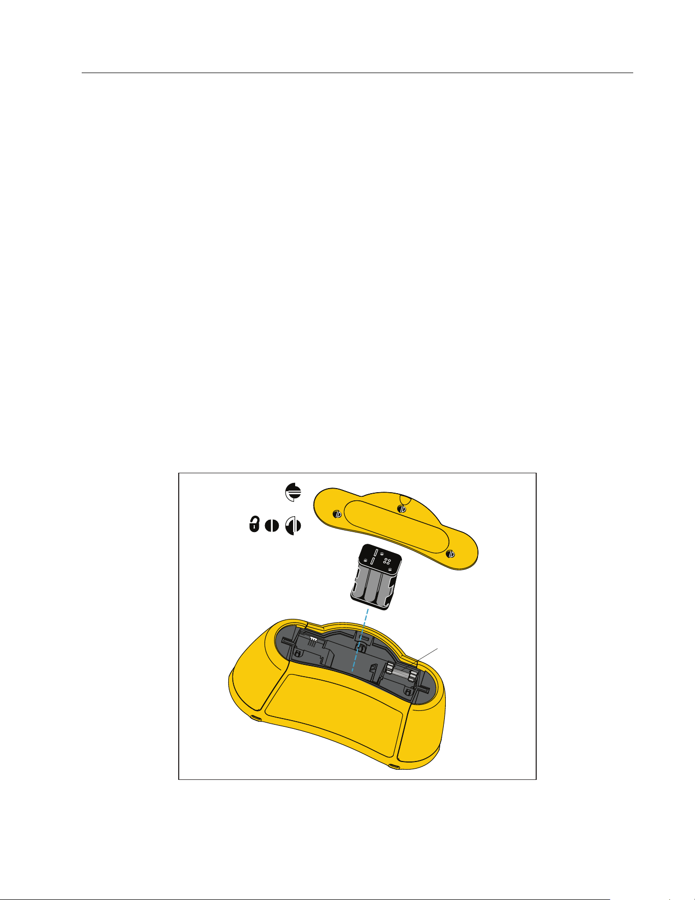
Multifunction PV Analyzer
Maintenance
43
Battery Replacement
Replace the batteries with six AA batteries. Alkaline batteries are supplied with the Tester.
XW Warning
To prevent possible electrical shock, fire, or personal injury:
Remove the test leads and any input signals before you replace the battery.
Install ONLY specified replacement fuses with the amperage, voltage, and
interrupt ratings shown in the Specifications section of this manual.
To replace the batteries (see Figure 3):
1. Push
to turn off the PV Analyzer.
2. Remove the test leads from the terminals.
3. To remove the battery door, use a standard-blade screwdriver to turn the battery door
screws (x3) one-quarter turn counterclockwise.
4. Push the release latch and slide the battery holder out of the Tester.
5. Replace the batteries.
6. Replace the battery holder and the battery door.
7. Turn the battery door screws one-quarter turn clockwise to fasten the door.
Figure 3. Battery Replacement
W FF 630 mA
1000 V IR 30 kA
1.888.610.7664 sales@GlobalTestSupply.com
Fluke-Direct.com

SMFT-1000
Users Manual
44
Product Disposal
Dispose of the Product in a professional and environmentally appropriate manner:
Delete personal data on the Product before disposal.
Remove batteries that are not integrated into the electrical system before disposal and
dispose of batteries separately.
If this Product has an integral battery, put the entire Product in the electrical waste.
1.888.610.7664 sales@GlobalTestSupply.com
Fluke-Direct.com


