HELIX Series
Operations Manual
532509-5EN_B
Thank You!
Thank you for choosing Humminbird®, the #1 name in marine electronics. Humminbird has built its reputation by designing and
manufacturing top quality, thoroughly reliable marine equipment. Your Humminbird is designed for trouble-free use in even the
harshest marine environment. We encourage you to read this manual carefully in order to get the full benefit from all the features
and applications of your Humminbird product.
Contact Humminbird Technical Support at humminbird.com or call 1-800-633-1468.
WARNING! This device should not be used as a navigational aid
to prevent collision, grounding, boat damage, or personal injury.
When the boat is moving, water depth may change too quickly
to allow time for you to react. Always operate the boat at very
slow speeds if you suspect shallow water or submerged objects.
WARNING! The electronic chart in your Humminbird unit is an
aid to navigation designed to facilitate the use of authorized
government charts, not to replace them. Only official
government charts and notices to mariners contain all of the
current information needed for the safety of navigation, and the
captain is responsible for their prudent use.
WARNING! Humminbird is not responsible for the loss of
data files (waypoints, routes, tracks, groups, recordings,
etc.) that may occur due to direct or indirect damage to the
unit’s hardware or software. It is important to back up your
control head’s data files periodically. Data files should also
be saved to your computer before restoring the control head
defaults or updating the software. See the following sections
of your Humminbird manual: Manage Screen Snapshots and
Recordings and Manage your Navigation Data: Import/Export
Navigation Data.
WARNING! Disassembly and repair of this electronic unit
should only be performed by authorized service personnel. Any
modification of the serial number or attempt to repair the original
equipment or accessories by unauthorized individuals will void the
warranty.
WARNING! Do NOT leave the control head microSD or SD card
slot cover open. The slot cover should always be closed to
prevent water damage to the unit.
WARNING! Do not travel at high speed with the unit cover
installed on the control head. Remove the unit cover before
traveling at speeds above 20 mph.
WARNING! The user shall maintain 20 cm separation from the
RF device to ensure compliance with RF exposure.
NOTE: Some features discussed in this manual require a
separate purchase, and some features are only available on
international models. Every effort has been made to clearly
identify those features. Please read the manual carefully in
order to understand the full capabilities of your model.
NOTE: The illustrations in this manual may not look the same as
your product, but your unit will function in a similar way.
NOTE: To purchase accessories for your control head, visit our
Web site at humminbird.com or contact Humminbird Technical
Support at 1-800-633-1468.
NOTE: The procedures and features described in this manual
are subject to change without notice. This manual was written
in English and may have been translated to another language.
Humminbird is not responsible for incorrect translations or
discrepancies between documents.
NOTE: Product specifications and features are subject to change
without notice.
NOTE: Humminbird verifies maximum stated depth in saltwater
conditions, however actual depth performance may vary due
to transducer installation, water type, thermal layers, bottom
composition, and slope.
ROHS STATEMENT: Product designed and intended as a fixed
installation or part of a system in a vessel may be considered beyond
the scope of Directive 2002/95/EC of the European Parliament and of
the Council of 27 January 2003 on the restriction of the use of certain
hazardous substances in electrical and electronic equipment.
ATTENTION INTERNATIONAL CUSTOMERS: Products sold in the U.S.
are not intended for use in the international market. Humminbird
international units provide international features and are designed
to meet country and regional regulations. Languages, maps, time
zones, units of measurement, and warranty are examples of
features that are customized for Humminbird international units
purchased through our authorized international distributors.
To obtain a list of authorized international distributors, please visit
our Web site at humminbird.com or contact Humminbird Technical
Support at (334) 687-6613.
2

360 Imaging®, AUTOCHART®, AUTOCHART® LIVE, ChartSelect®, CoastMaster™, Contour XD™, Down Imaging®, DualBeam PLUS™, Fish ID+™, FishSmart™, HELIX®,
Humminbird®, HumminbirdPC™, ICE HELIX® CHIRP Series, i-Pilot® Link™, LakeMaster®, MEGA Down Imaging™, MEGA Down Imaging+™, MEGA Imaging™, MEGA Side
Imaging™, MEGA Side Imaging+™, Real Time Sonar™, RTS™, RTS Window™, Side Imaging®, SI™, Structure ID™, SwitchFire®, UniMap™, WhiteLine™, X-Press™ Menu,
are trademarked by or registered trademarks of Johnson Outdoors Marine Electronics, Inc.
Adobe, Acrobat, Adobe PDF, and Reader are either registered trademarks or trademarks of Adobe Systems Incorporated in the United States and/or other countries.
Baekmuk Batang, Baekmuk Dotum, Baekmuk Gulim, and Baekmuk Headline are registered trademarks owned by Kim Jeong-Hwan.
The Bluetooth® word mark and logos are registered trademarks owned by the Bluetooth SIG, Inc. and any use of such marks by Johnson Outdoors, Inc. is under license.
Other trademarks and trade names are those of their respective owners.
microSD and SD are trademarks or registered trademarks of SD-3C, LLC in the United States, other countries or both.
Navionics® Gold, HotMaps™, and HotMaps™ Premium, Navionics® Classic Charts, Navionics+™, and Platinum™ Cartography are trademarked by or registered trademarks
of Navionics S.p.A.
NMEA 2000® is a registered trademark of the National Marine Electronics Association.
© 2021 Johnson Outdoors Marine Electronics, Inc. All rights reserved.
3

4
Warnings 2
Introduction 7
Using Humminbird Manuals on your Mobile Device or PC 10
Getting Started 11
HELIX Control Head 20
Update Software 27
Menu System Overview 28
Open an X-Press Menu. . . . . . . . . . . . . . . . . . . . . . . . . . . . . . . . . . . 28
Open the Main Menu .....................................28
Select a Menu ..........................................29
Change a Menu Setting ..................................29
Tips for Using the Menu System ..........................30
Change the User Mode (Angler or Custom). . . . . . . . . . . . . . . . . 31
Close the Menu System ..................................31
Views 32
Display a View. . . . . . . . . . . . . . . . . . . . . . . . . . . . . . . . . . . . . . . . . . . 32
Show your Favorite Views ................................33
Save a View to the VIEW SHORTCUT Key ...................33
Display Digital Readouts .................................34
Combo Views ...........................................38
Set up Sonar 39
Display a Sonar View On-Screen 52
Understand the Sonar Views ............................. 54
Customize the Sonar View ............................... 55
Adjust Sonar Display Settings ............................ 60
Adjust Settings While you Fish ............................64
Compare Sonar Beams (Split Sonar View) ................. 69
Review Sonar History .................................... 70
Zoom In/Zoom Out ......................................71
Navigation in Sonar Views ................................ 75
Display a Down Imaging View On-Screen 78
Understand the Down Imaging View .......................80
Customize the Down Imaging View ........................ 81
Adjust Settings While you Fish ............................84
Review Down Imaging History and Zoom In/Out ............ 89
Navigation in Down Imaging Views ........................91
Display a Side Imaging View On-Screen 93
Understand the Side Imaging View ........................ 95
Customize the Side Imaging View ......................... 97
Adjust Settings While you Fish ...........................100
Review Side Imaging History and Zoom In/Out ............107
Navigation in Side Imaging Views ........................109
Ice Fishing Overview 111
Understand the Flasher View ............................112
Adjust Settings While you Fish ...........................113
Move the Depth Cursor .................................117
Zoom In/Out in Flasher View .............................118
Using Sonar Zoom View in Ice Fishing Mode. . . . . . . . . . . . . . . 120
Charge Glow-in-the-Dark Lures ......................... 122
Manage Screen Snapshots and Recordings 123
Chart Overview 131
Display a Chart View On-Screen .........................132
Select a Map Source ....................................134
Customize the Bird’s Eye View ...........................140
Customize the Chart Instrument View ....................141
Customize the Chart View ...............................142
Display Chart Overlays ..................................146
Display Humminbird LakeMaster
Contour Lines and Depth Ranges ......................148
Display Humminbird CoastMaster
Contour Lines and Depth Ranges ......................150
Change the Chart Orientation and Motion Mode ...........152
Navigation Overview 154
Navigation Alarms Overview .............................156
Man Overboard (MOB) Navigation ........................157
Waypoints 159
Routes 168
Tracks 173
Search 176
Table of Contents

5
Manage your Navigation Data 178
Manage Waypoints .....................................181
Manage Routes ........................................185
Manage Tracks .........................................192
Manage Groups ........................................194
Search and Organize ...................................198
Import/Export Navigation Data ..........................200
Delete All Navigation Data and Reset .....................200
AutoChart Live Overview 201
Plan your Map .........................................201
Prepare the Control Head for Mapping ....................202
Record your Custom Map ...............................205
Stop Recording ........................................206
Correct Data ...........................................206
Using AutoChart Live in Ice Fishing Mode .................207
Open the AutoChart Live Menu ...........................208
Display the AutoChart Live Map ..........................208
Customize the AutoChart Live Map Display Settings .......210
Customize the Bottom Hardness Display Settings .........215
Customize the Vegetation Display Settings ...............219
Set Up a NMEA 2000 Network 223
Understand the NMEA 2000 Instrument View .............227
Manage your Control Head 228
Maintenance 234
Troubleshooting 235
Specifications 237
Statements and Acknowledgements 346
Contact Humminbird 348
Table of Contents

6
7
Introduction
Introduction
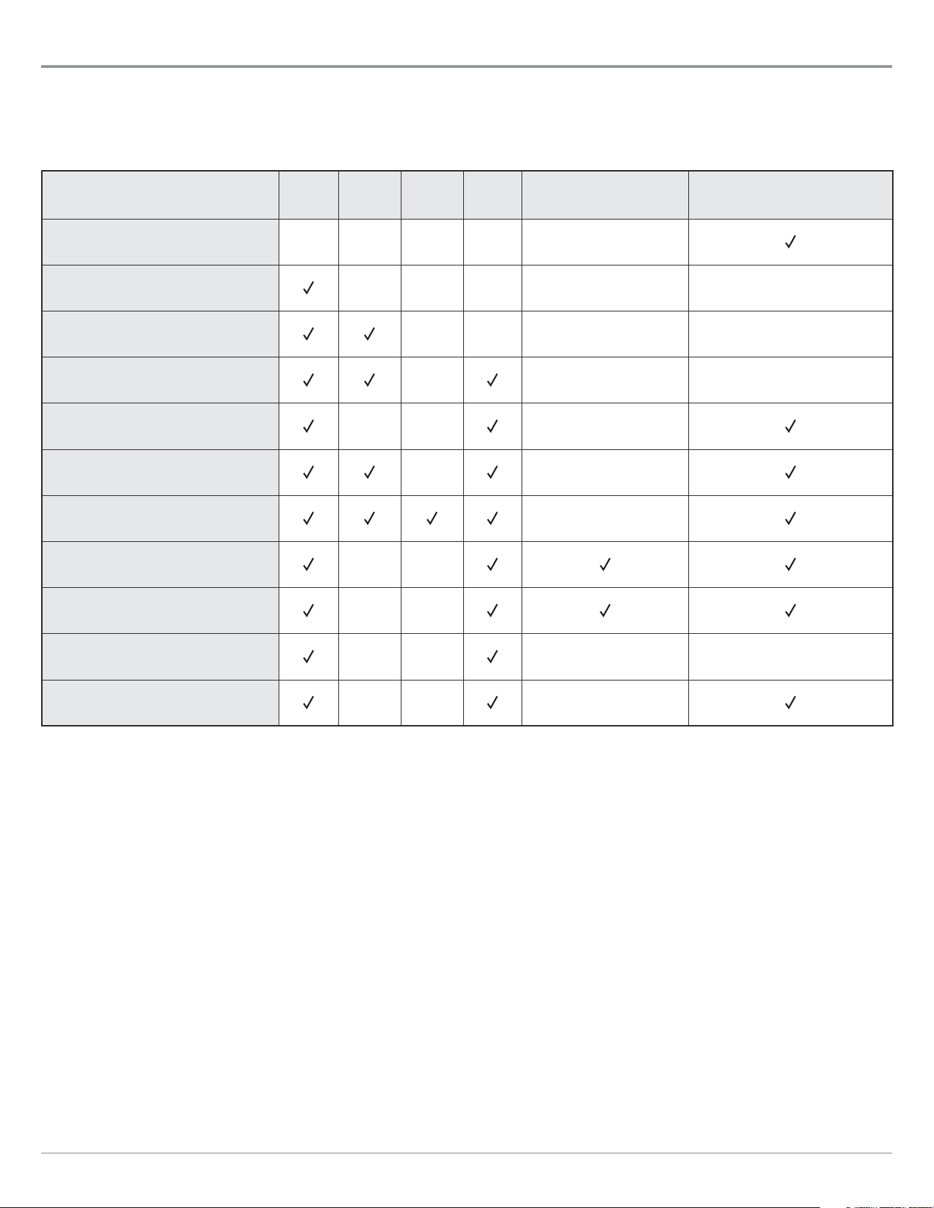
The instructions in this manual describe the HELIX control head operations. Review the following tables to understand the features
that apply to your control head.
HELIX G2/G2N Series
Model
Sonar
(2D)
Down
Imaging
Side
Imaging
CHIRP
Ethernet
(optional)
GPS
(Charts and Navigation)
HELIX GPS G2
HELIX SONAR G2
External GPS, trackplotting
(separate purchase required)
HELIX DI G2
External GPS, trackplotting
(separate purchase required)
HELIX CHIRP DI G2
External GPS, trackplotting
(separate purchase required)
HELIX CHIRP GPS G2/G2N G2N models only
HELIX CHIRP DI GPS G2/G2N G2N models only
HELIX CHIRP SI GPS G2/G2N G2N models only
HELIX CHIRP MEGA SI GPS G2N MEGA MEGA
HELIX CHIRP MEGA DI GPS G2N MEGA
ICE HELIX CHIRP G2
External GPS, trackplotting
(separate purchase required)
ICE HELIX CHIRP GPS G2/G2N
G2N models
(in Open Water Mode only)
8
Introduction
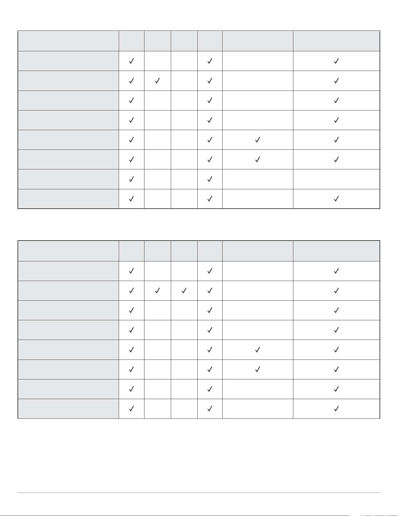
HELIX G3/G3N Series
Model
Sonar
(2D)
Down
Imaging
Side
Imaging
CHIRP
Ethernet
(optional)
GPS
(Charts and Navigation)
HELIX CHIRP GPS G3/G3N
G3N models only
HELIX CHIRP DI GPS G3
HELIX CHIRP MEGA DI GPS G3/G3N
MEGA G3N models only
HELIX CHIRP MEGA SI GPS G3/G3N
MEGA MEGA G3N models only
HELIX CHIRP MEGA DI+ GPS G3N
MEGA+
HELIX CHIRP MEGA SI+ GPS G3N
MEGA+ MEGA+
ICE HELIX CHIRP G3
External GPS, trackplotting
(separate purchase required)
ICE HELIX CHIRP GPS G3/G3N
G3N models
(in Open Water Mode only)
HELIX G4/G4N Series
Model
Sonar
(2D)
Down
Imaging
Side
Imaging
CHIRP
Ethernet
(optional)
GPS
(Charts and Navigation)
HELIX CHIRP GPS G4/G4N
G4N models only
HELIX CHIRP SI GPS G4
HELIX CHIRP MEGA DI GPS G4/G4N
MEGA G4N models only
HELIX CHIRP MEGA SI GPS G4/G4N
MEGA MEGA G4N models only
HELIX CHIRP MEGA DI+ GPS G4N
MEGA+
HELIX CHIRP MEGA SI+ GPS G4N
MEGA+ MEGA+
ICE HELIX CHIRP GPS G4
ICE HELIX CHIRP MEGA SI+ GPS G4N
MEGA+ MEGA+
In Open Water Mode only

Operations Summary Guide: For an overview of functions, see the Operations Summary Guide (or Quick Start Guide) included with
your product.
Accessories: Some of the features shown in this manual require a separate purchase. Radar, AIS, Compass/Heading Sensor,
Ethernet, i-Pilot Link, etc. require a separate purchase. For the list of accessories that are compatible with your control head, visit
our Web site at humminbird.com. To install each accessory, use the installation guide provided with it, or download the guide from
our Web site.
Ethernet Models: Visit our Web site at humminbird.com to purchase Ethernet cables and switches, and to download the Ethernet
Networking Installation and Operations Manual.
Register and Update: Visit our Web site at humminbird.com to register your product(s), update control head and accessory
software, and purchase additional equipment. Also, see Update Software in this manual for more information.
9
Introduction
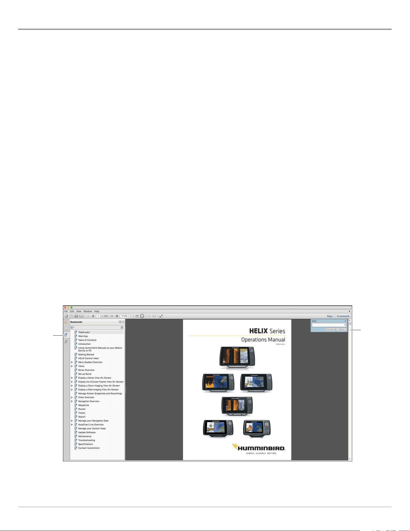
Using Humminbird Manuals on your Mobile Device or PC
The Humminbird manuals for your control head and accessories can be downloaded to your mobile device or PC. If you prefer to
use a hard copy for reference, this manual may be printed.
Download the Manual to your Mobile Device
1. Download the free Adobe Acrobat Reader app to your mobile device.
2. Go to our Web site at humminbird.com, and click Support > Manuals.
3. Select the PDF for your control head model or accessory, and save it to your device.
4. Open the Adobe Acrobat Reader app.
5. Open the Humminbird manual.
Download the Manual to your PC
1. Download the free Adobe Acrobat Reader software from http://get.adobe.com/reader/, and install it on your PC.
2. Go to our Web site at humminbird.com, and click Support > Manuals.
3. Select the PDF for your control head model or accessory, and save it to your device.
4. Open Adobe Acrobat Reader.
5. Open the Humminbird manual.
Jump to a Section: Click a section name in the Bookmarks panel. Bookmarks can be expanded and collapsed by clicking on
the plus (+) or minus (-) icons.
Search for Words or Phrases: Press and hold the Ctrl F keys on your PC keyboard. Type the word(s) into the text box.
Print: If you prefer to use a hard copy for reference, this manual may be printed.
Using the Manual
search for
key words
(Ctrl + F)
bookmarks
panel
10
Introduction
Getting Started
The procedures in this section describe how to get started with your control head. Some of the settings in this section are a one-time
set up, and other settings (such as checking the GPS reception) you will use each time you hit the water.
Power On
Follow the instructions below to power on your Humminbird control head.
1. Press the
POWER key.
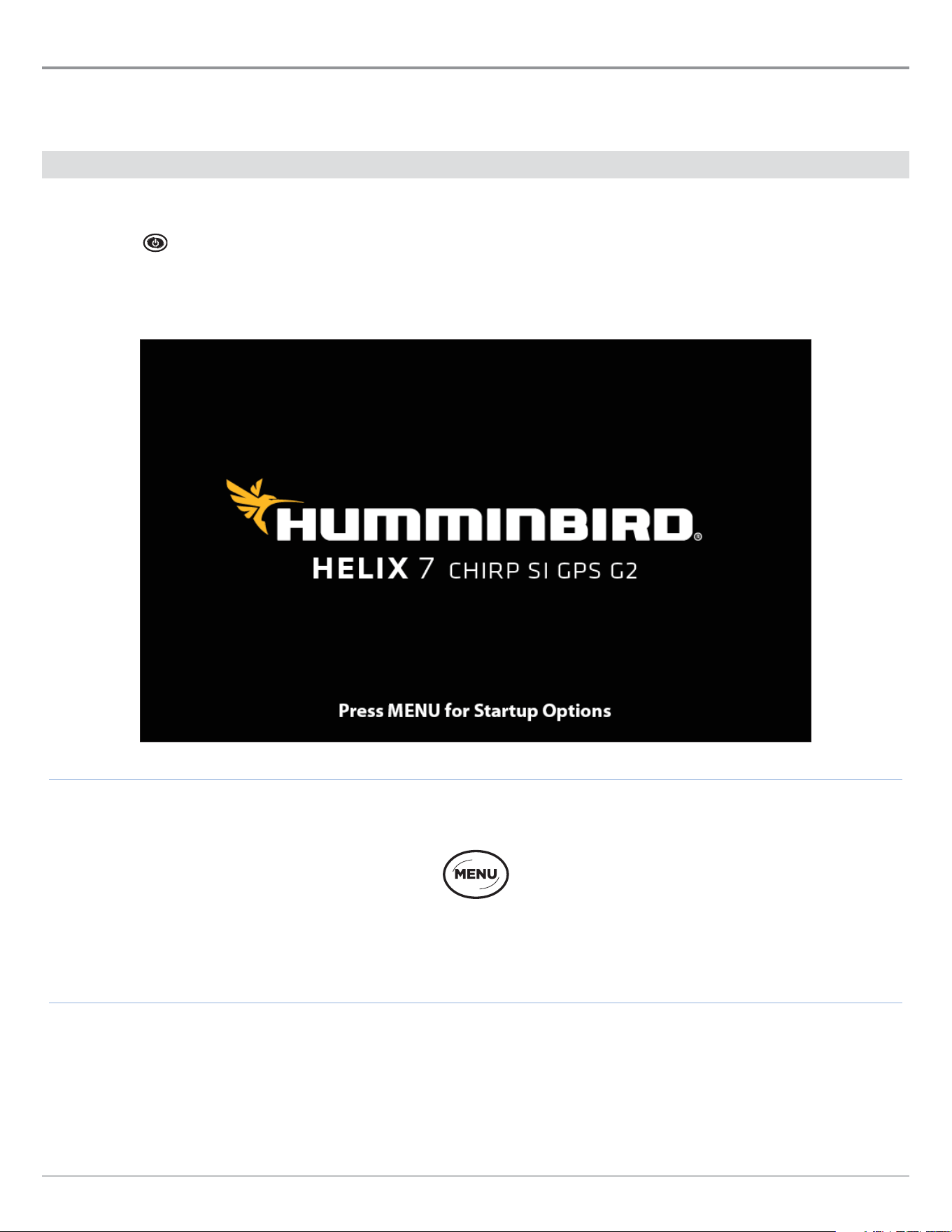
2. When the Title screen is displayed, press the MENU key.
Press the MENU key
Title Screen
3. Select Normal. Press the RIGHT Cursor key.
11
Getting Started
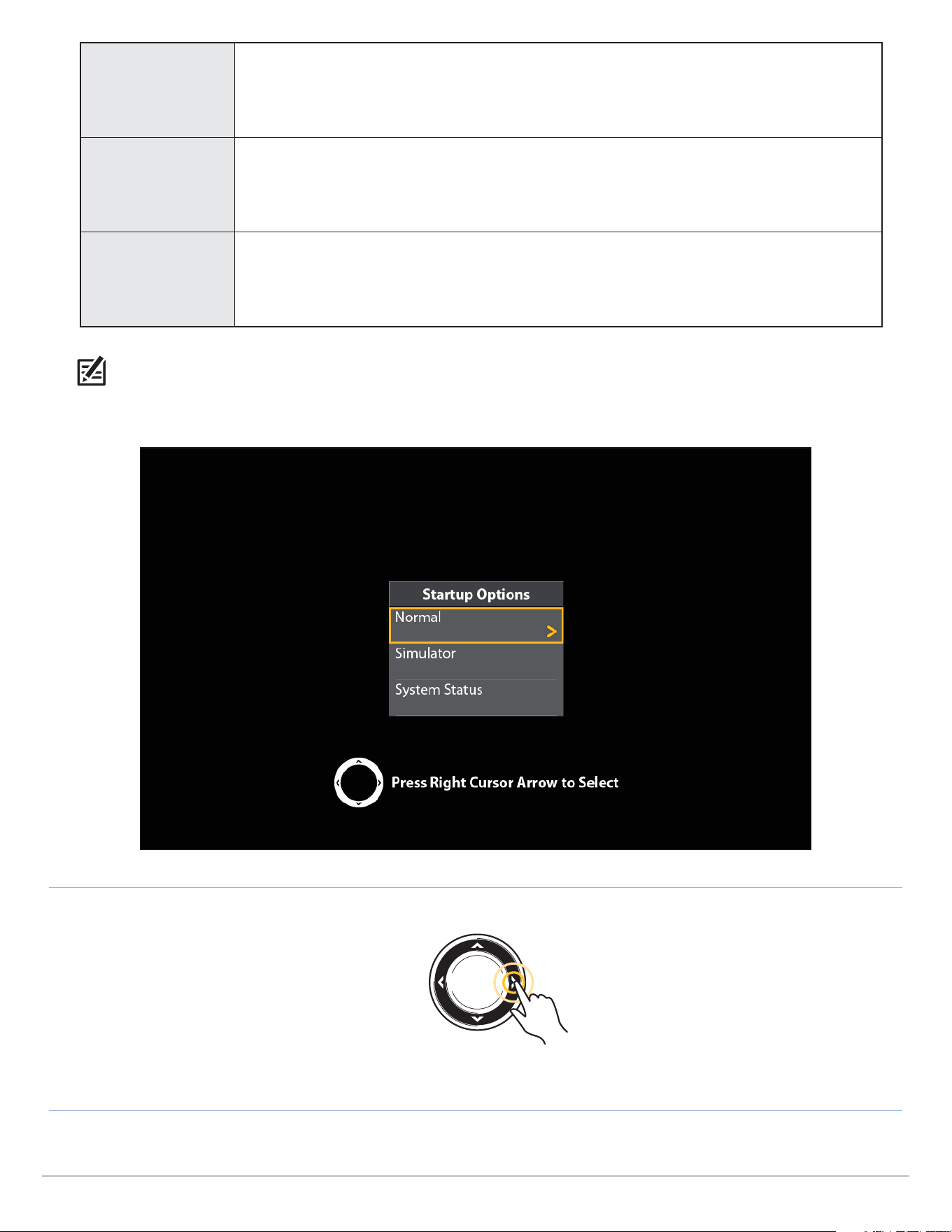
Normal
Normal mode is required for on-the-water operation. If a functioning transducer is connected
to the control head, Normal will be selected automatically, and your control head can be used
on the water.
Simulator
To learn how to use your control head, select Simulator. You can save menu settings and
navigation data in Simulator mode (see Chart Overview and Navigation Overview for more
information).
System Status
To view system information for software version, GPS reception, and accessory connections,
select System Status. See Check Accessory Connections and Check GPS Reception for more
information.
NOTE: If you wait too long to select a start-up option, the system will start the mode that is already highlighted. If your control head
goes into Demonstration mode, please note that menu settings cannot be saved in this mode (see Manage your Control Head).
Starting Normal Mode for on-the-water Operations
Press the
RIGHT Cursor key
12
Getting Started
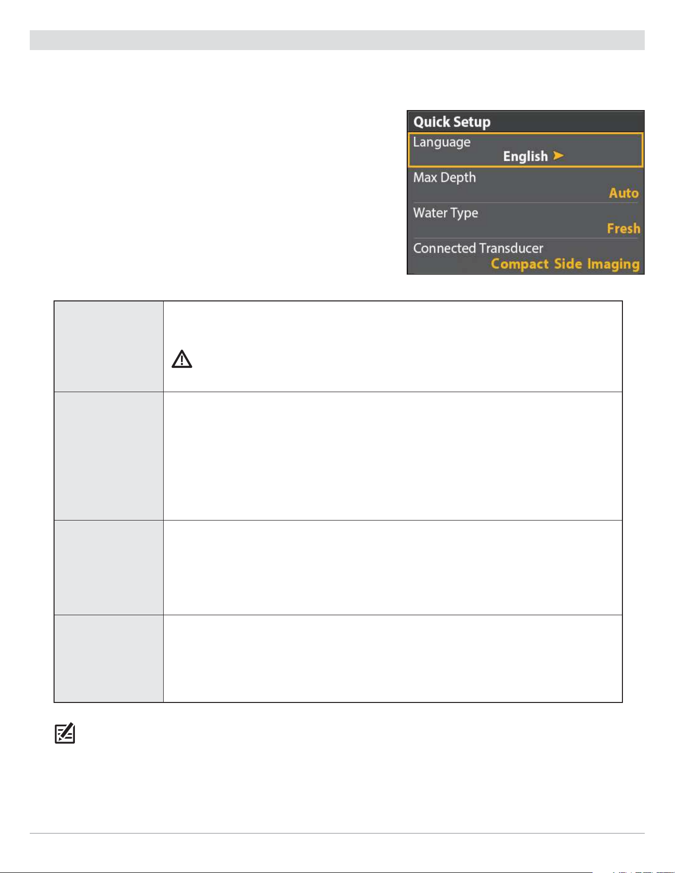
Quick Setup
If this is the first time the unit has been powered on (after installation or after restoring defaults), the Quick Setup menu will display.
Set up the Control Head
1. Use the Cursor Control key to change the settings.
2. Close: Press the EXIT key.
Language
The available languages are determined by your Humminbird model.
WARNING! Do NOT enable Asian Mode if you do not require Asian languages. Before you select
Asian Mode, contact Technical Support for important information.
Max Depth
Set the maximum depth of the body of water. When Max Depth is set to Auto, the control head
will acquire bottom readings as needed (within the capabilities of the unit). When Max Depth
is set to match your water maximum depth, the control head will not attempt to acquire sonar
data below that depth, so more detail will be shown on the display.
Side Imaging units default to the Side Imaging range setting if the SI Range is set deeper than
the Max Depth. See the Side Imaging section for more information.
Water Type
Water Type affects the accuracy of deep water depth readings and configures the control head
for operation in fresh or salt water.
In salt water, you can also choose the shallow or deep setting. If the depth is more than 330 ft
(100 m), select Salt (deep).
Connected
Transducer
The control head will automatically select the transducer that was included with your control
head. If your model is compatible with an accessory transducer, and it is connected to the
control head, select the transducer in the system so the beams are activated and the related
views are added to the control head.
NOTE: To change the Max Depth, Water Type, and the Connected Transducer after the initial Setup, see Set up Sonar.
Quick Setup Menu
13
Getting Started
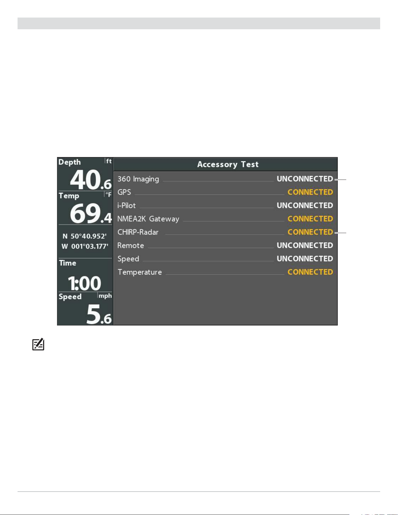
Check Accessory Connections
If you’ve connected other separate-purchase equipment to the control head, such as AIS, Compass/Heading Sensor, and more, use
these instructions to confirm the equipment is detected and communicating with the control head. You can also check Ethernet
accessory connections from this view.
1. Press and hold the VIEW key.
2. Select System > Accessory Test.
Confirm all accessories are listed as Connected. If you have a temp/speed wheel, the wheel must move for it to be detected.
Unconnected: If an accessory is listed as Unconnected, check the cable and power connections to confirm they are secure
and powered on. Review the installation guide that was included with your accessory to confirm it is installed correctly.
To change the NMEA 2000 network, see Set Up a NMEA 2000 Network.
Confirming Accessories are Detected (HELIX 9 CHIRP SI GPS G2N)
connected
unconnected
(not detected
by the control
head)
NOTE: The menus for installed accessories are typically included in the Accessory tab in the Main Menu. See your accessory guide
for details. For the latest list of accessories that are compatible with your control head, visit our Web site at humminbird.com.
14
Getting Started
15
Getting Started
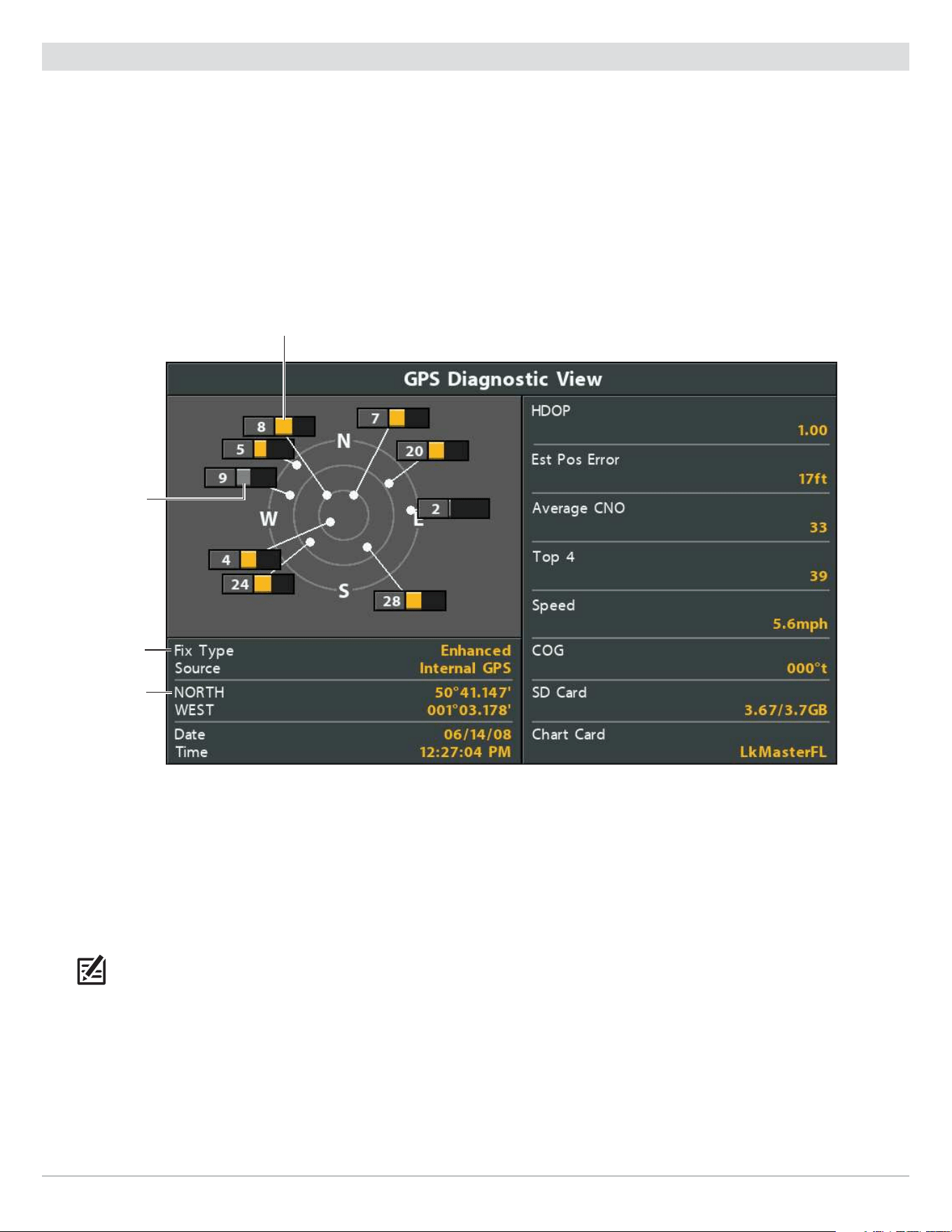
Check GPS Reception
If your control head includes internal GPS, or if it is connected to an External GPS receiver, use the instructions in this section to
confirm the control head has GPS reception.
1. Press and hold the VIEW key.
2. Select System > GPS Diagnostic View.
Confirm GPS Fix Type is shown as Enhanced or 3D.
Confirm that the latitude/longitude position readout is displayed.
Reviewing GPS Reception
active satellite signal strength (yellow)
fix type shown as
enhanced
latitude/longitude
position
monitored satellite
signal strength
(gray)
GPS Reception: The sky chart displays the satellite number and signal strength bar.
GPS Fix Type: reported as No Fix, 2D Fix, 3D Fix, or Enhanced. An Enhanced Fix has been augmented using information from
WAAS, EGNOS, or MSAS.
HDOP (the Horizontal Dilution of Precision): a GPS system parameter which depends on the current satellite configuration.
HDOP is used to calculate the Estimated Position Error.
NOTE: To manually change your GPS source, change the output frequency, or turn on GLONASS, see Manage your Control Head.

16
Getting Started
Set Alarms
When an alarm is turned on, an alert will sound or display on the control head to indicate the threshold has been exceeded.
Turn on Alarms and Adjust Settings
1. Main Menu: Press the MENU key twice.
OR
To open the Main Menu from a System View, press the MENU key once.
2. Select the Alarms tab.
3. Select an alarm menu. Press the RIGHT or LEFT Cursor keys to adjust the threshold.
Depth Alarm
The alarm will be triggered when the depth becomes equal to or less than the menu setting.
Transducer required.
Fish ID Alarm
The alarm will be triggered when a fish is detected based on the menu setting. See Adjust
Sonar Display Settings for more information.
Low Battery Alarm
The alarm will be triggered when the input battery voltage is equal to or less than the menu
setting. The battery must be connected to the control head. Set the alarm to a level that will
alert you when the battery is low but at a level that is high enough to start the engine and run
essential electronics. See your control head installation guide for more information.
Temp. Alarm
The alarm will be triggered when the water temperature detected by the control head is
equal to the temp alarm setting. Input from the built-in transducer temperature sensor or a
temperature accessory is required.
Off Course Alarm
Sets how far the boat can move off course during navigation before an alarm will be triggered.
GPS required. See Navigation Overview for more information.
Arrival Alarm
Sets how close the boat must be to the destination waypoint before the alarm will be triggered.
GPS required. See Navigation Overview for more information.
Drift Alarm
Sets how far the boat can move from its anchored position outside the drift alarm perimeter
before an alarm will be triggered. GPS required. See Navigation Overview for more information.
NOTE: The available alarms are determined by the connected equipment, so your control head may provide more or less options than
the information shown here. If there are accessories installed, review the accessory guide for alarm information.
4. Close: Press the EXIT key twice.
Exit an Alarm
If an alarm is triggered during control head operation, you can close it or silence it using these instructions.
1. Press any key on the control head.

17
Getting Started
Change Units of Measurement
Use the instructions in this section to change the units of measurement format.
HELIX G3/G3N and older HELIX G4N
1. Main Menu: Press the MENU key twice.
2. Select the Setup tab.
3. Select Units - Depth, Units - Distance, etc., and adjust
each
unit
setting
as needed.
4. Close: Press the EXIT key.
NOTE: You can also change the time and date format,
language, and installation offsets from this menu. See
Manage your Control Head for more information.
1. Main Menu: Press the MENU key twice.
2. Select the Data Sources tab.
3. Select Units and press the RIGHT Cursor key to open the
Units menu.
4. Select each
unit
as needed and use the RIGHT or LEFT Cursor
keys to adjust the setting.
5. Close: Press the EXIT key.
Reset the Triplog
The Triplog includes the timer for elapsed time, distance traveled since last reset, and average speed. Use the following instructions
to reset the triplog. To display the Triplog as a digital readout, see Views: Display Digital Readouts.
HELIX G3/G3N and older HELIX G4N
1. Main Menu: Press the MENU key twice.
2. Select the Setup tab.
3. Select Triplog Reset.
4. Press the RIGHT Cursor key.
5. Follow the on-screen prompts.
1. Main Menu: Press the MENU key twice.
2. Select the Data Sources tab.
3. Select Reset Trip Log.
4. Press the RIGHT Cursor key.
5. Follow the on-screen prompts.
Turn on/o Sounds
Use the instructions in this section to choose the category of sounds you want to hear from your control head.
1. Main Menu: Press the MENU key twice.
2. Select the Setup tab.
3. Select Sound Control.
4. Select All Sounds or Alarms Only.
To receive a sound alert from an alarm, Sound Control must be set to All Sounds or Alarms Only.
Change the Alarm Tone: Select the Alarms tab > Alarm Tone.
Change the User Mode
The User Mode determines how many menu options are displayed in the menu system. Select Angler to see fewer menu options
that are used more often. Select Custom to see all the menu options available in the menu system.
Instructions in this manual marked with Main Menu (Custom User Mode) indicate that the menu system User Mode must be set
to Custom for the selected menu to be shown. If you do not see the menu in the system, change the User Mode to Custom. See
Menu System Overview for details.
1. Main Menu: Press the MENU key twice.
2. Select the Setup tab.
3. Select User Mode.
4. Select Angler or Custom.

18
Getting Started
Set up Sonar
If you’ve installed an accessory transducer, or to refine your sonar settings or turn on/off Ice Fishing Mode, see Set up Sonar for
details.
Set up Chart Preferences
If you’ve installed a microSD or SD map card, see Chart Overview to set up the map source.
Pair a Phone with the Control Head (HELIX G2N/G3N/G4N Series only)
If you have a HELIX G2N, G3N or G4N Series control head, you can pair a phone with it using Bluetooth wireless technology.
Pair a Phone with the Control Head
HELIX G2N and G3N HELIX G4N
1. Main Menu: On the HELIX control head, press the MENU
key twice.
2. Open the Phone Bluetooth Menu: Select the Accessories
tab.
Select Phone Bluetooth. Press the RIGHT Cursor key.
3. Select Bluetooth.
4. Select On.
5. Select Connect New Phone. Press the RIGHT Cursor key.
It will take a moment for this option to appear in the
menu.
6. Follow the on-screen prompts to start the pairing process.
If the phone is not found, select Search for Phone. Press
the RIGHT Cursor key.
7. When the phone name displays in the menu, select it.
Press the RIGHT Cursor key.
8. Check your phone. When prompted, tap Pair on your
phone.
9. In your phone Settings menu, turn on Show Notifications.
1. Main Menu: On the HELIX control head, press the MENU
key twice.
2. Open the Phone Bluetooth Menu: Select the Accessories
tab.
Select Phone Bluetooth. Press the RIGHT Cursor key.
3. Select Connect Phone. Press the RIGHT Cursor key.
4. Follow the on-screen prompts to start the pairing process
through your phone.
5. When prompted, tap Pair on your phone.
6. In your phone Settings menu, turn on Show Notifications.
Change the Phone Bluetooth Alert Format
Use the following instructions to select an alert format on the control head or turn off alerts.
1. On the HELIX control head, open the Phone Bluetooth menu.
NOTE: In your phone Settings menu, confirm that Bluetooth is turned on and Show Notifications is turned on.
2. Select Text Message Alerts or Phone Call Alerts.
Press the RIGHT or LEFT Cursor keys to select an alert format. To turn off notifications, select off.
3. Select Sounds. Select On or Off.

19
Getting Started
Review Phone Bluetooth Notifications
Use the Views X-Press Menu to review notifications.
1. Press and hold the VIEW key.
Reviewing Phone Bluetooth Information
text
notifications
call
notifications
phone battery
power percentage
phone carrier
signal strength
Adjust the Backlight
1. Press the POWER key.
2. Select Light.
3. Adjust the Backlight setting from Dim to 10 (brightest).
Start Standby Mode
To conserve power while the control head is not in-use, start Standby mode.
1. Press the POWER key.
2. Select Standby.
3. Press the RIGHT Cursor key.
4. Turn off: Press the POWER key.
Power O
Use the following instructions to power off your control head. Your control head should always be turned off using the POWER key.
If you are currently navigating, you should save the current track before powering off.
Save the Current Track
1. Chart X-Press Menu: With a Chart View displayed on-screen, press the MENU key once.
2. Select Save Current Track.
3. Press the RIGHT Cursor key.
Power Off
1. Press and hold the POWER key.
20
The Control Head
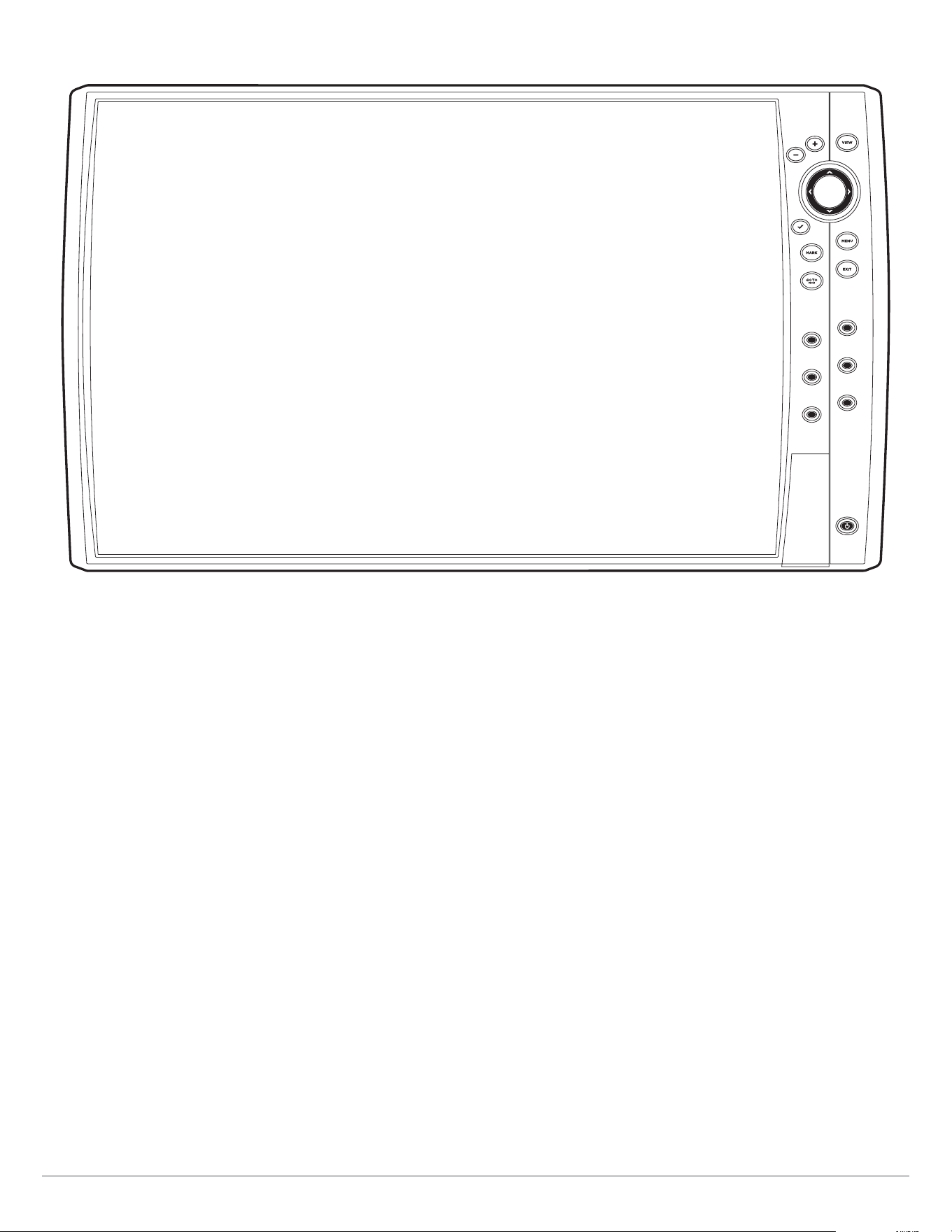
HELIX Control Head
VIEW
MENU
EXIT
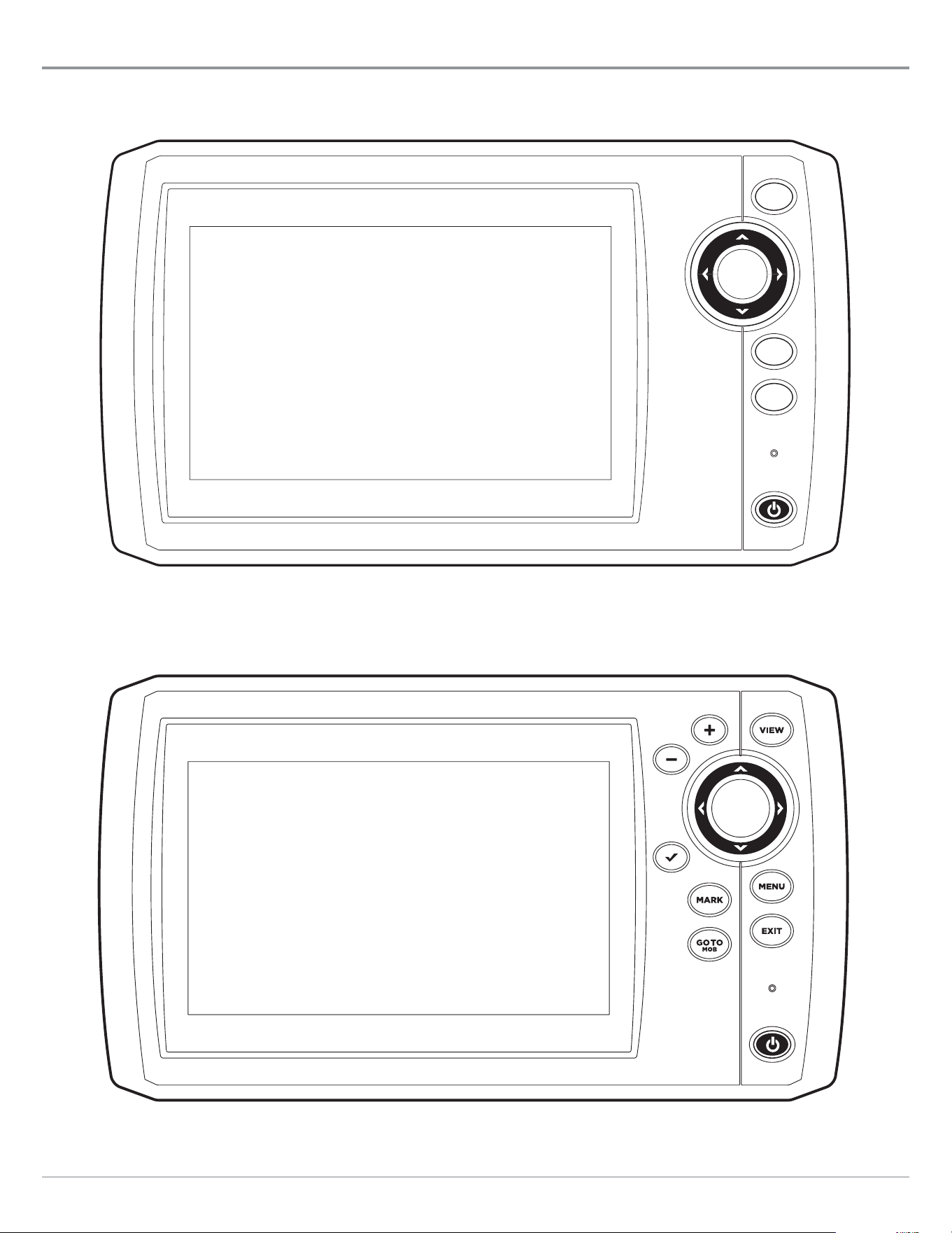
HELIX 5 SONAR G2, HELIX 5 DI G2, ICE HELIX 5 CHIRP G2
HELIX 5 G3 Series, ICE HELIX 5 CHIRP GPS G2, ICE HELIX 5 G3 Series
HELIX 7 SONAR G2, HELIX 7 CHIRP DI G2
HELIX 7 G2/G2N, G3/G3N, and G4 Series Models (with Internal GPS), ICE HELIX 7 CHIRP GPS G3/G3N and G4
21
The Control Head
22
The Control Head
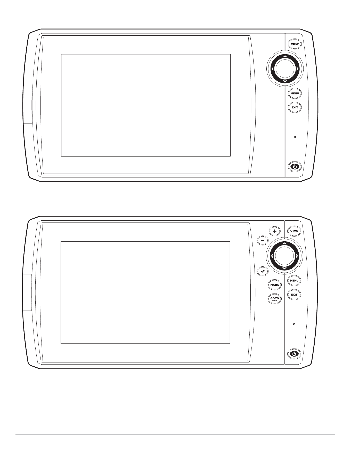
HELIX 7 G4N Series
HELIX 8, 9, 10, 12 G2N/G3N/G4N Series
23
The Control Head
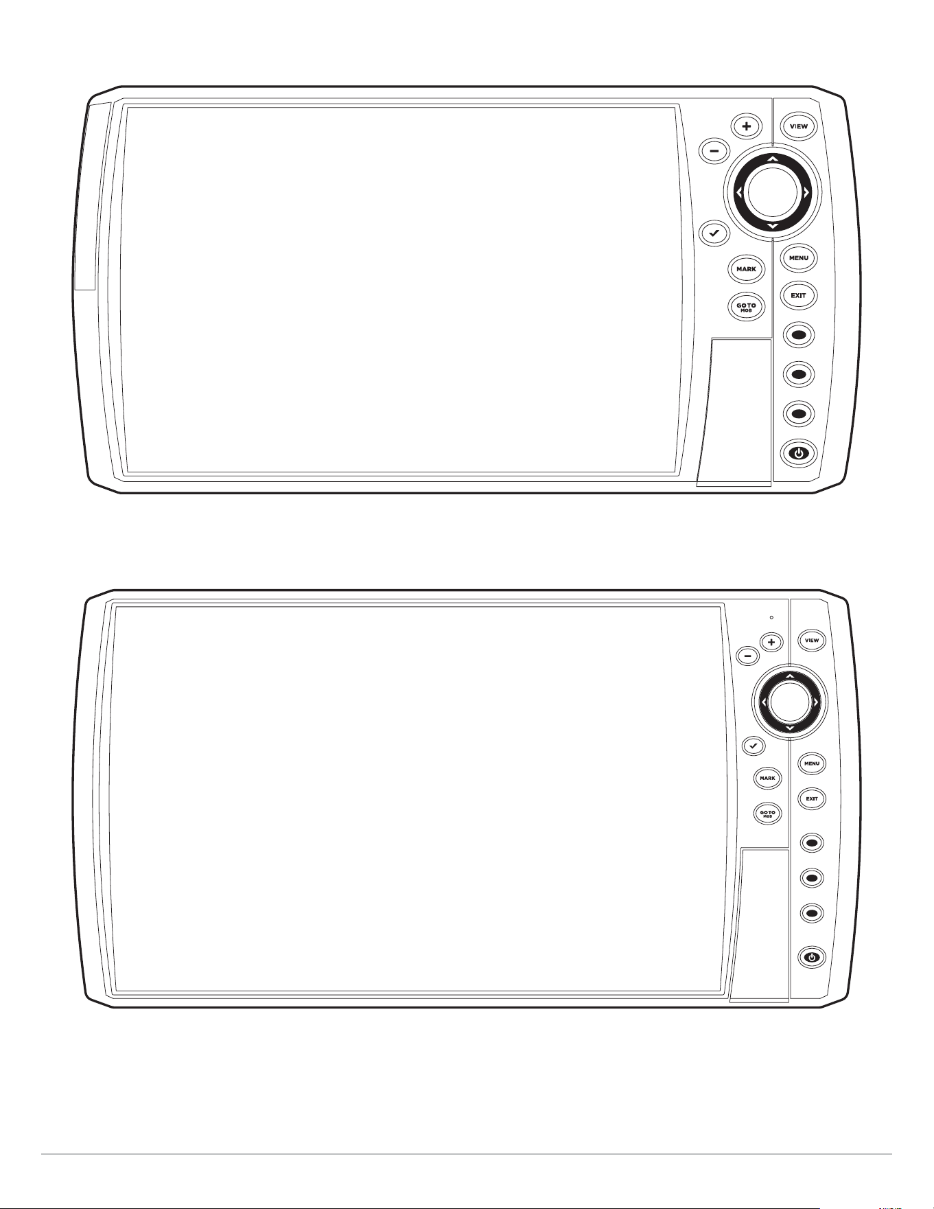
HELIX 15 G4N
24
The Control Head
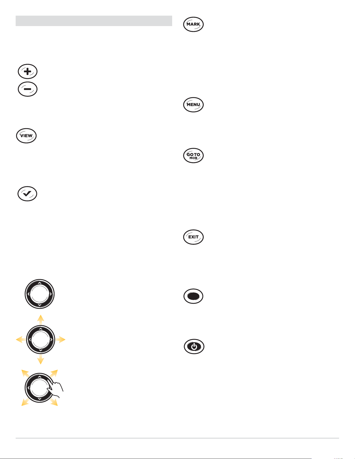
Control Head Keys
The available keys are determined by your control head model.
Your control head might not include all the keys shown in this
section.
ZOOM In (+)/ZOOM Out (–) keys
Press the ZOOM keys to change the scale of the
view. For a closer view, press the ZOOM IN (+) key.
For a wider view, press the ZOOM OUT (-) key. You
can also magnify the cursor selection. You can also
press these keys to adjust the sensitivity in sonar
views (Sonar, DI, SI).
VIEW key
Press and hold the VIEW key to open the Views
X-Press menu, or press the VIEW key repeatedly until
the view you want to use is displayed on the screen.
Press the EXIT key to display the previous view. See
Views for details.
CHECK/INFO key
In the Chart View, press the CHECK/INFO key to
see information about the cursor position or about
objects located near the cursor position. If the cursor
is not active, the Chart Info submenu will open. See
Navigation Overview for details.
In Sonar Views, press this key once to switch
frequencies (if available). See each sonar section
(Sonar, DI, SI) for details.
Cursor Control key
(LEFT, RIGHT, UP, or DOWN Cursor keys)
Press the arrows on the Cursor Control key
to move through the menu system, select
menus, and change or activate menu
settings. See Menu System Overview for
details.
Also, press any arrow on the Cursor Control
key to move the cursor on the view.
To move the cursor diagonally, press in
between the arrows.
MARK key
Press the MARK key to save a waypoint at the boat
position. If the cursor is active, press the MARK key
twice to save a waypoint at the cursor position. See
Navigation Overview for details.
If a microSD or SD card is installed, press and hold
this key to save a Screen Snapshot. See Manage
Screen Snapshots and Recordings for details.
MENU key
To open the X-Press Menu for the on-screen view and
operation mode, press the MENU key once. To open
the Main Menu, press the MENU key twice. See Menu
System Overview for details.
GO TO/Man Overboard (MOB) key
With an active cursor, press the GOTO key twice to
create a waypoint and start navigation towards that
waypoint. If the cursor is not
active,
press the GOTO
key, and choose
from the saved navigation data.
To start Man Overboard navigation, press and hold
the GOTO key. See Navigation Overview and Man
Overboard (MOB) Navigation for details.
EXIT key
Press the EXIT key to close a menu, close a dialog
box, turn off an alarm, or exit Cursor mode.
Also, press the EXIT key to scroll through the View
Rotation in reverse order. See Views for details.
VIEW SHORTCUT key
Press and hold a VIEW SHORTCUT key to save a
shortcut to the on-screen view. You can save one
view on each VIEW SHORTCUT key. See Views for
details.
POWER key
Press the POWER key to power on the control head.
To power off, press and hold the
POWER
key.
During operation, press the POWER key. The backlight
can be adjusted from this menu. You can also turn
on/off Sonar, change the view background color, and
start Standby mode.
25
The Control Head
SD Card or microSD Card Slot
Your control head may be compatible with an SD or microSD card (separate purchase required). Use it to update software, add
detailed charts to your control head, import/export navigation data, and save sonar recordings and screen snapshots. Use the
instructions in this section to install the card.
Add Maps: see Chart Overview.
Import/Export Navigation data: See Manage your Navigation Data.
Sonar Recordings and Screen Snapshots: See Manage Screen Snapshots and Recordings.
Software Updates: For details, see Update Software.
CAUTION! Before the control head software is updated or restored to system defaults, export your navigation
data (see
Update
Software
).
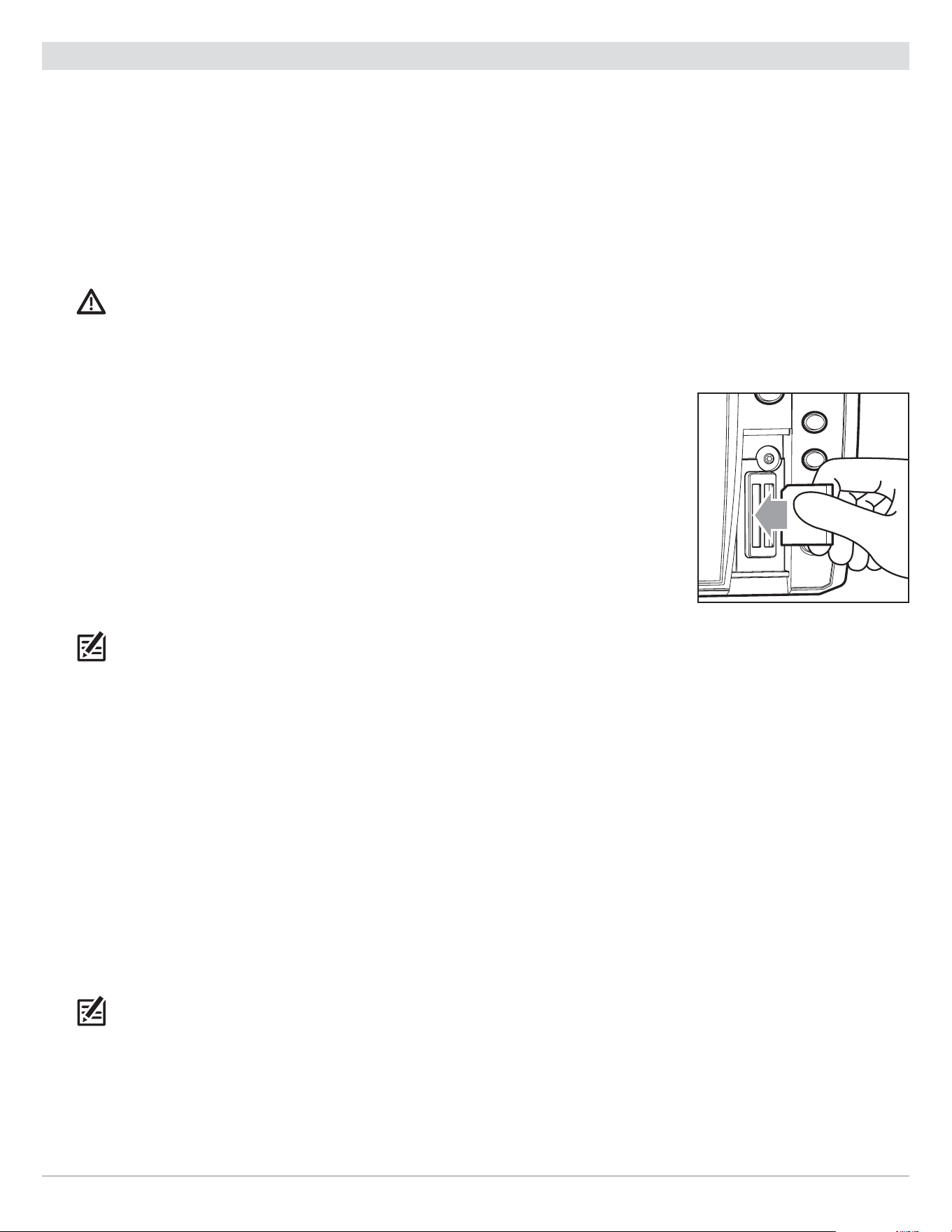
Insert an SD Card
Follow these steps if your control head is compatible with SD cards.
1. Remove the SD card slot cover.
2. Position the SD card so that the label faces to the left.
3. Insert the card into the slot until it clicks into place.
4. Replace the slot cover so it is secure.
5. Remove: Press the card into the slot and then release it. The card will eject. Pull the card
carefully from the slot.
NOTE: Do not leave the SD card slot cover open. The slot cover should always be closed to
prevent water damage to the unit.
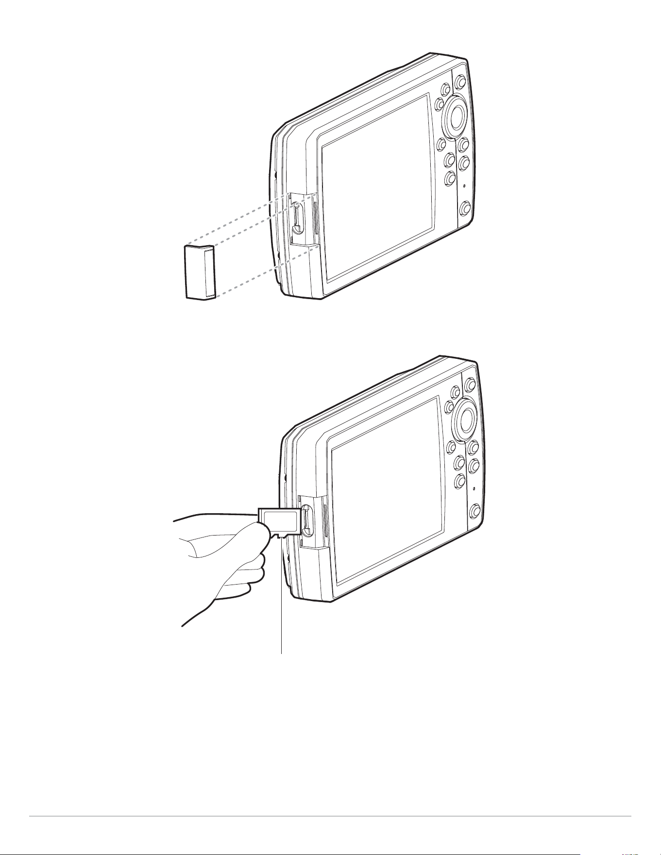
Insert a microSD Card
Follow these steps if your control head is compatible with microSD cards.
1. Remove the microSD card slot cover.
2. Side Card Slot: Position the microSD card so that the label faces the front of the control head and the card notches face
down.
Front Card Slot: Position the microSD card so that the label faces to the left and the card notches face up.
3. Insert the card into the slot until it clicks into place.
4. Replace the slot cover so it is secure.
5. To Remove: Press the card into the slot and then release it. The card will eject. Pull the card carefully from the slot.
NOTE: Do not leave the card slot cover open. The slot cover should always be closed to prevent water damage to the unit.
Insert the SD card with the
label facing to the left
26
The Control Head
Removing the microSD Card Slot Cover (HELIX 5, HELIX 7)
Installing a microSD Card (magnified view)
(HELIX 5, HELIX 7)
notch facing down

27
Update Software
Update Software
Register your product at humminbird.com so that you will receive the latest Humminbird news and software updates for your
Humminbird model. You can also download HumminbirdPC, which allows you to manage your waypoints, routes, and tracks on your
personal computer.
If your control head model does not include a microSD or SD card slot, you can use HumminbirdPC to update the control head
software. Visit humminbird.com for details.
NOTE: It is important to back up your control head’s data files (waypoints, routes, tracks, groups, recordings, etc.) periodically.
Data files should also be saved to your PC before restoring the unit’s defaults or updating the software. See Manage your
Navigation Data:
Import/Export Navigation Data
and Manage Screen Snapshots and Recordings for more information. Also,
contact Humminbird Technical Support with any questions.
Required Equipment: Personal computer with Internet access, and a formatted microSD or SD card. See HELIX Control Head for
compatibility details.
Register your Humminbird Products
Register your Humminbird product and sign up to receive the latest Humminbird news, including software updates and new product
announcements.
1. Go to our Web site at humminbird.com and click Support > Register your Product.
2. Follow the on-screen instructions to register your product.
Update the Control Head Software
Use the following instructions to download software updates from humminbird.com.
1. Install a formatted microSD or SD card into the slot on your PC.
2. Download: Click Support > Software Updates. The available software updates are listed as Downloads under each product.
• Under Downloads, click the file name. Confirm the file name is for your control head model.
• Read the instructions in the dialog box and select Download.
• Follow the on-screen prompts to save the software file to the microSD or SD card.
3. Install the microSD or SD card with the updated software file into the control head card slot.
4. Power On: The control head will recognize the new software and run through a series of prompts to confirm the software
installation.
28
Menu System Overview
Menu System Overview
The menu system provides menu options that are determined by the operations mode, on-screen view, and connected accessories.
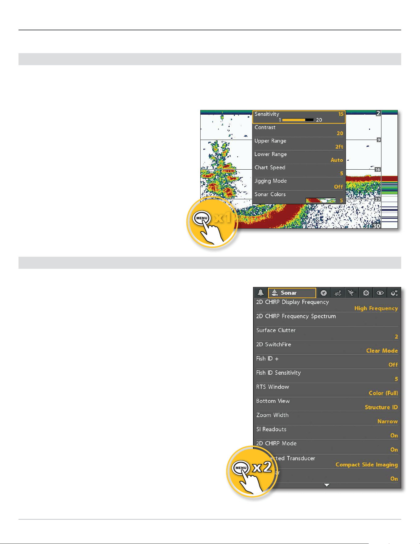
Open an X-Press Menu
The X-Press Menu displays menus that are related to the on-screen view and the operations mode (such as navigation). In this
illustration, the Sonar X-Press Menu is displayed because the Sonar View is displayed on the screen.
Open the X-Press Menu
1. Press the VIEW key repeatedly until the view you
want is displayed on-screen.
2. Press the MENU key once.
Open the Main Menu
The main menu is divided into tabbed categories (Alarms, Sonar, Navigation,
Chart, Humminbird Chart, Setup, Views, and Accessories). The available tabs
and menus are determined by your model and the connected accessories.
Open the Main Menu
1. Press the MENU key twice.
Opening the Sonar X-Press Menu
xx11
Opening the Main Menu
29
Menu System Overview
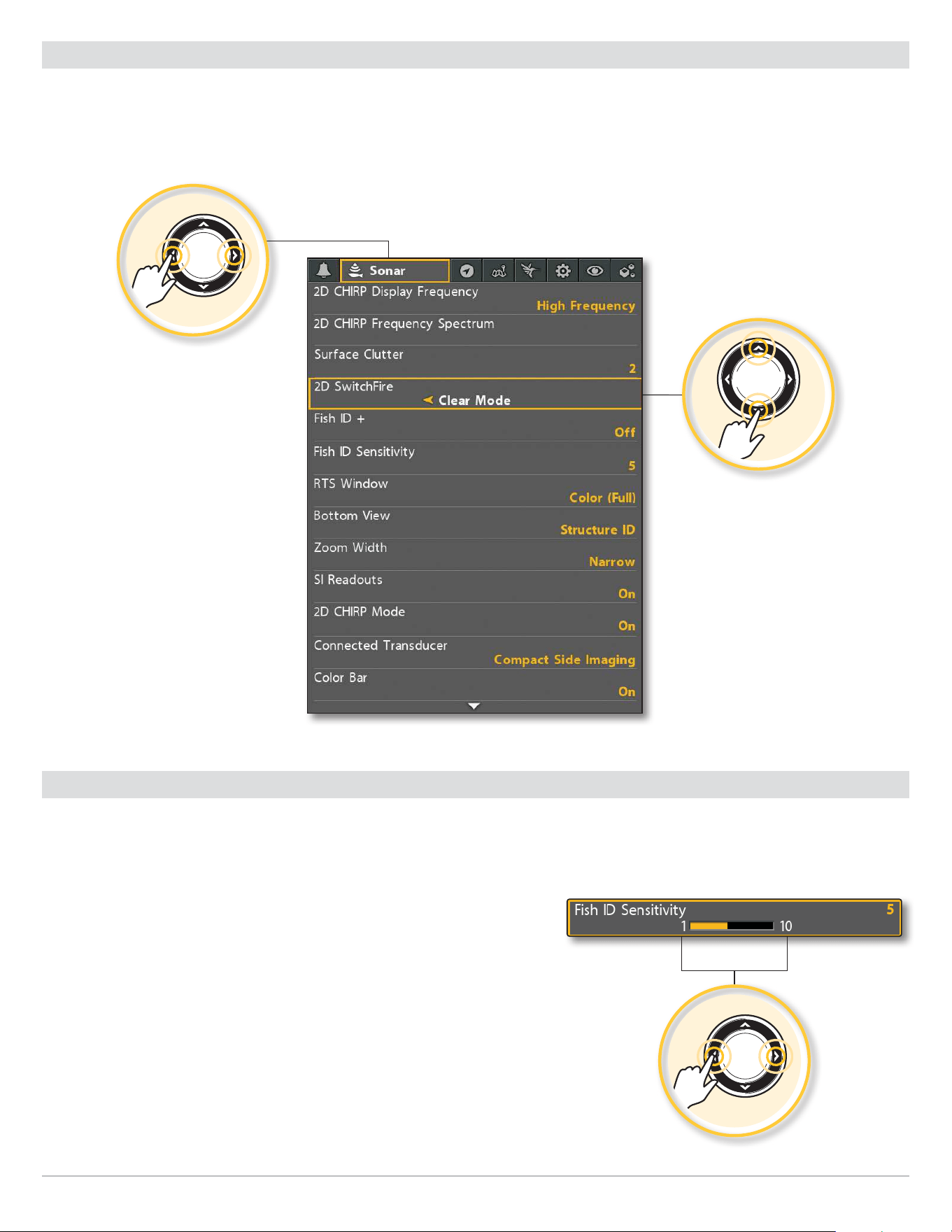
Select a Menu
Use the Cursor Control key to select a menu in the Main Menu or X-Press Menu.
Select a Tab (Main Menu) Select a Menu
1. Press the RIGHT or LEFT Cursor keys. 1. Press the DOWN or UP Cursor keys.
Select a Menu
Select a Tab
Change a Menu Setting
Use the Cursor Control key to change menu settings or start an action. When you change a menu setting, the view will update immediately.
Adjust a Menu Setting
1. Press the RIGHT or LEFT Cursor keys.
Change a Menu Setting
30
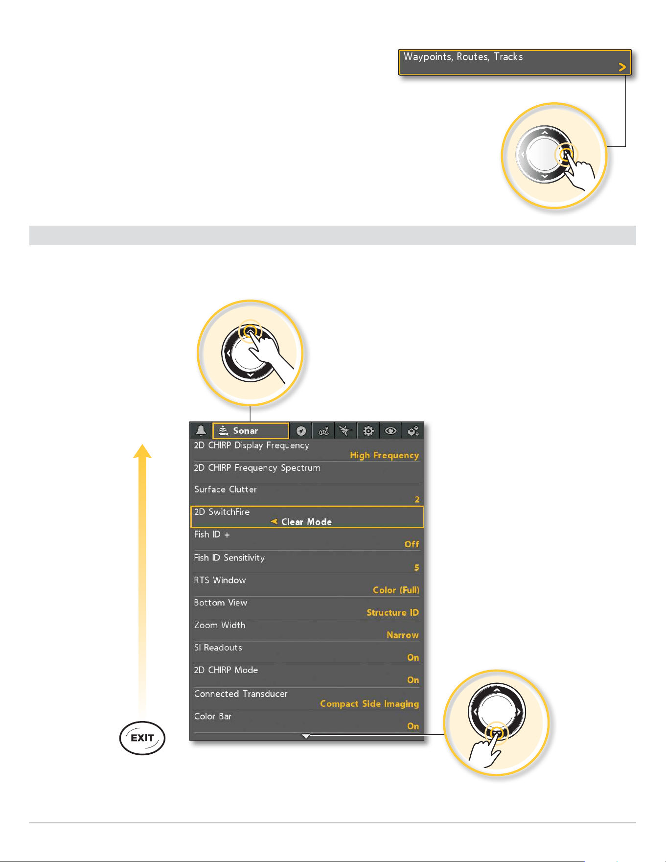
Menu System Overview
Start an Action/Open a Submenu
1. If a menu has a right arrow on it, press the RIGHT Cursor key to start the
action or open the submenu.
Tips for Using the Menu System
You can move through the menu system quickly using the following tips.
Jump to the Bottom of the Tab
Jump to the Top of the Tab
See More Menus
Start an Action or Open a Submenu
31
Menu System Overview
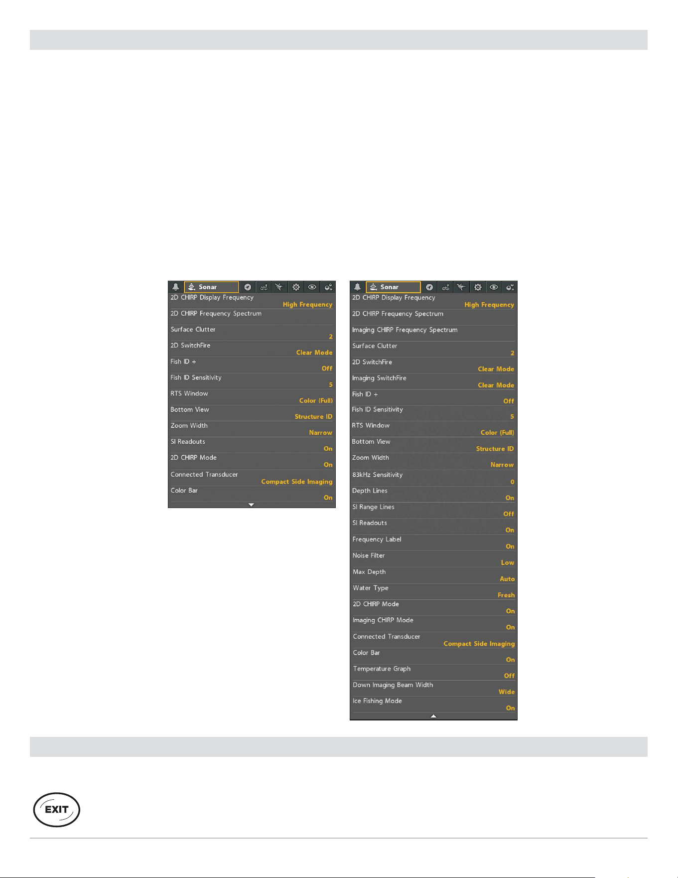
Change the User Mode (Angler or Custom)
The User Mode determines how many menus are shown in the menu system. Select Angler to see fewer menus that are used more
often. Select Custom to see all the menus available in the menu system.
Main Menu (Custom User Mode): Instructions in this manual marked with Main Menu (Custom User Mode) indicate that the menu
system User Mode must be set to Custom for the selected menu to be shown. If you do not see the menu in the system, change
the User Mode to Custom.
Change the User Mode
1. Main Menu: Press the MENU key twice.
2. Select the Setup tab.
3. Select User Mode.
4. Select Angler or Custom.
Main Menu: Sonar Tab
(User Mode set to Angler)
Main Menu: Sonar Tab
(User Mode set to Custom)
Close the Menu System
Use the EXIT key to go back through the menu system or close the menu system.
Back: Press the EXIT key to close the current menu and go back one level in the menu system.
Close: Press the EXIT key repeatedly until the menu system is closed.
32
Views
Views
The HELIX control head has many options to display data on-screen, and the data can be displayed in a variety of ways. There are
also several ways to quickly display a view on-screen. To see the list of views available on your control head, see Show your Favorite
Views.
Display a View
The available views are determined by the control head model, installed transducer, and connected accessories.
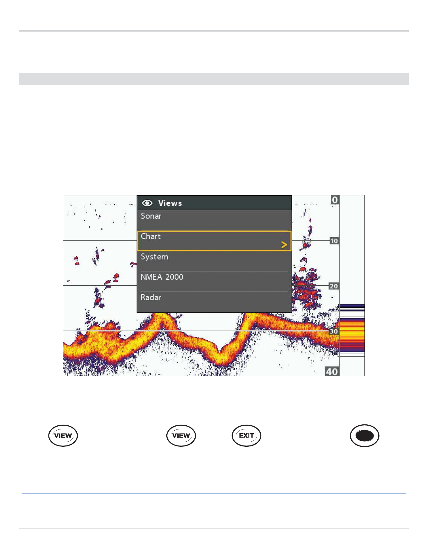
Display a View from the Views X-Press Menu
1. Press and hold the VIEW key.
2. Select a view category. Press the RIGHT Cursor key.
3. Select a view. Press the RIGHT Cursor key.
Selecting a View to Display on the Screen
Forward: Press to go
to the Next View
Back: Press to go to
the Previous View
Press to Display
a Saved View
Press and Hold to Open
the Views X-Press Menu
OR OR
33
Views
Display the Next/Previous View
Next View: Press the VIEW key repeatedly until the view you want is displayed on-screen.
Previous View: Press the EXIT key repeatedly until the view you want is displayed on-screen.
Display a Saved View
1. Press a VIEW SHORTCUT key.
You can save one view on each VIEW SHORTCUT key. See Save a View to a VIEW SHORTCUT key for more information.
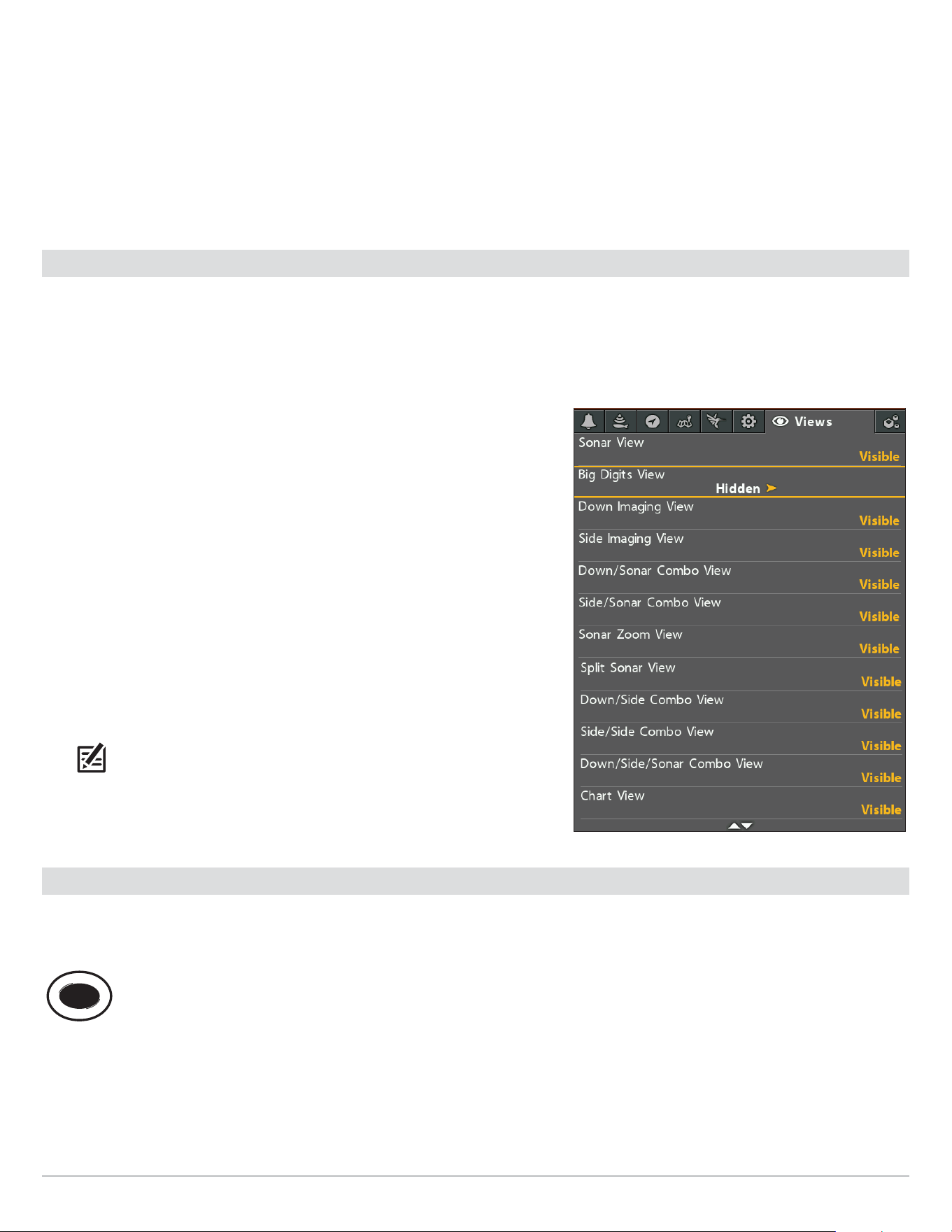
Show your Favorite Views
You can display or hide any view so that each time you press the VIEW key, only your favorite views are displayed on the screen. You
can also use the Views tab to see the list of views available on your control head. The available views are determined by your control
head model, installed transducer, and connected accessories.
Show/Hide a View
1. Main Menu: Press the MENU key twice.
2. Select the Views tab.
3. Select a view.
4. Select Hidden or Visible.
Hide Sonar Views
If you’re using your control head for GPS/Navigation functions only, use these
instructions to hide all sonar views from the view rotation. This setting also
deactivates sonar.
1. Press the POWER key.
2. Select Sonar.
3. Select Off.
NOTE: You can also turn on/off Sonar from the Main Menu > Setup tab > Sonar.
Save a View to a VIEW SHORTCUT key (HELIX 8, 9, 10, 12 only)
Another way to display your favorite views quickly is to save them on the VIEW SHORTCUT keys. You can program the VIEW SHORTCUT
keys to display a saved view immediately. You can save one view on each key.
With the view you want to save displayed on-screen, press and hold one of the VIEW SHORTCUT keys for several seconds.
Main Menu: Views Tab
34
Views
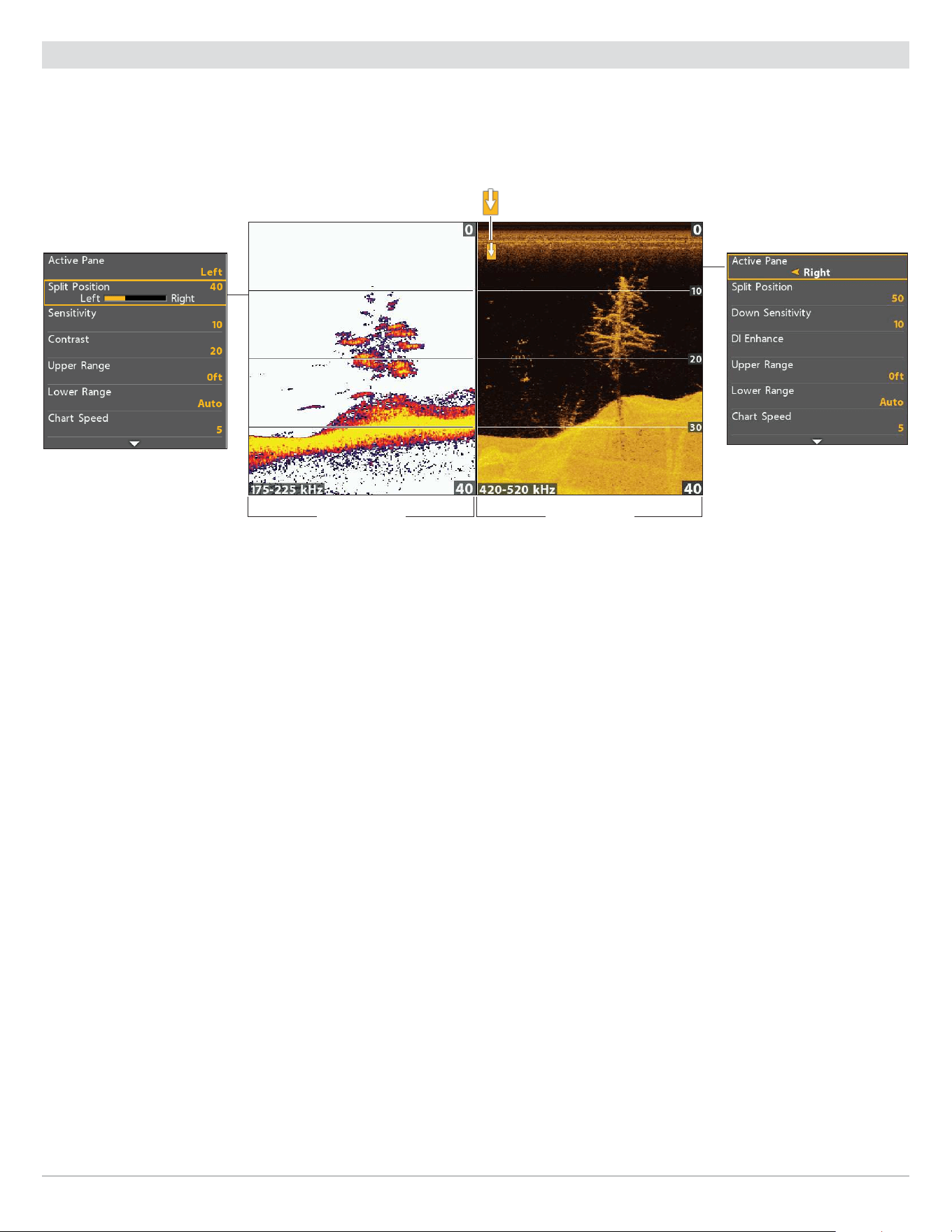
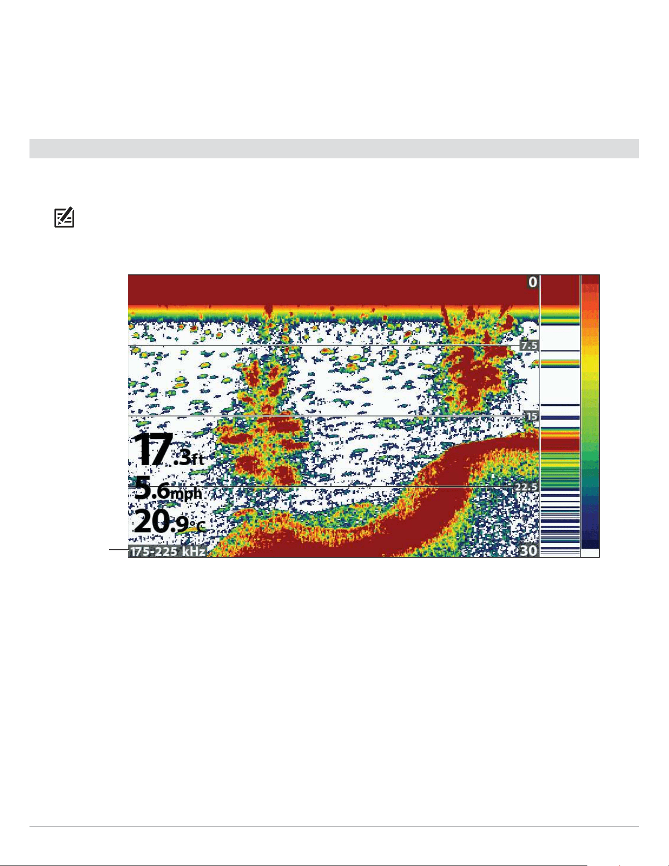
Display Digital Readouts
Digital Readout data can be displayed as an overlay, or it can be displayed in data boxes on the views. You can also choose which
digital readouts you want to display. The format and readouts you choose will be applied to all views.
Accessories: The available digital readouts are determined by the installed equipment, so if you connect accessories, additional
readouts will be available.
Format: You can change the digital readout format from the Setup Tab. See Manage your Control Head: Change Digital Readout
Formats for details.
Select the Digital Readout Type
Use the instructions in this section to display digital readouts in boxes or as overlays. You can also choose to hide the digital
readouts completely.
1. Main Menu: Press the MENU key twice. Select the Setup tab.
2. Select Digital Readouts.
3. Select one of the following options:
Boxes
Digital Readouts are displayed in boxes on the view. See the illustration Digital Readouts
with Boxes Selected. You can customize which digital readouts are displayed (see Customize
Digital Readouts).
Overlay
The digital readouts are displayed as an overlay on the view. See the illustrations Digital
Readouts with Overlay Selected. These digital readouts are fixed and cannot be changed.
Off
The digital readouts will be hidden completely. To hide individual digital readouts instead of
all, see Customize Digital Readouts.
Show/Hide Digital Readouts on the Side Imaging View (Side Imaging models only)
If you have Digital Readouts set to Boxes on all views, you can hide the digital readout boxes on the Side Imaging View
exclusively.
1. Main Menu: Press the MENU key twice. Select the Sonar tab.
2. Select SI Readouts.
3. Select On (show) or Off (hide).
35
Views
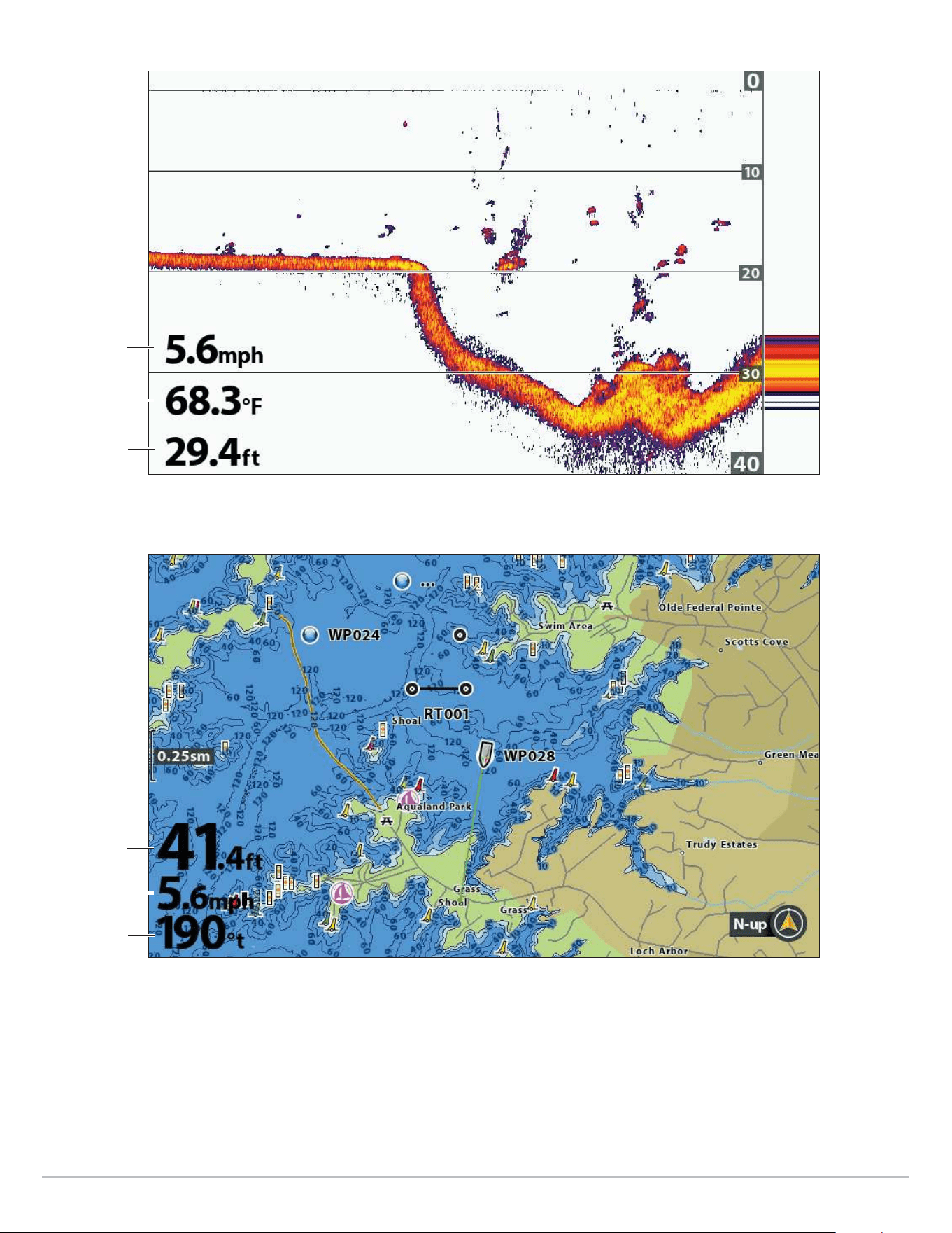
Digital Readouts with Overlay Selected (Sonar View)
temperature
depth
speed
Digital Readouts with Overlay Selected (Chart View [Map Source: Humminbird Basemap])
speed
course over
ground
depth
36
Views
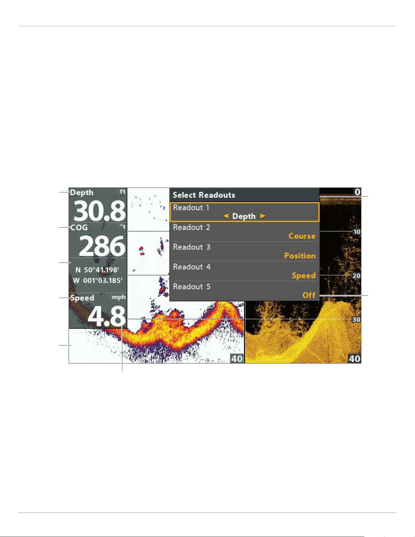
Customize Digital Readouts
If you have Digital Readouts set to Boxes, you can select the data that will be displayed in each box. Use the Select Readouts or
Edit Data Boxes menu to set your standard digital readouts. Use the Select Nav Readouts or Edit Navigation Data Boxes menu to
set the digital readouts that will be displayed during navigation.
HELIX G3/G3N and older HELIX G4N
1. Main Menu (Custom User Mode): Press the MENU key
twice. Select the Setup tab.
2. Select Select Readouts or Select Nav Readouts. Press the
RIGHT Cursor key.
3. Select a readout window (Readout 1, 2, 3, etc.).
4. Select a digital readout.
Hide: To hide a readout window, select Off.
1. Main Menu (Custom User Mode): Press the MENU key
twice. Select the Setup tab.
2. Select Edit Data Boxes or Edit Navigation Data Boxes.
Press the RIGHT Cursor key.
3. Select a Data Box (Data Box 1, 2, 3, etc.).
4. Select a digital readout.
Hide: To hide a data box, select Hide Data Box.
digits format set
to large tenths
Digital Readouts with Boxes Selected (Down/Sonar Combo View)
readout/data
box 2
readout/data
box 1
readout/data
box 5
(o = blank)
readout/data
box 4
readout/data
box 3
readout 5
turned o
select
readouts
menu
37
Views
Understand Digital Readouts
The following table displays the digital readouts that are available in the Select Readouts menu or the Select Nav Readouts menu.
The available digital readouts are determined by the installed equipment.
Label Name Description
Navigation
Readout
Bearing Bearing The direction to a destination waypoint measured in degrees from north.
COG
Course Over Ground
(Course)
The direction the boat is traveling measured in degrees from North.
When the COG is equal to Bearing, the boat is said to be on course and
will arrive at the destination in the most efficient manner.
Depth Depth
The depth of the water from the transducer or digital depth sensor
to the bottom. This measurement includes the depth offset setting.
If the depth number is flashing, it means the unit is having trouble
locating the bottom. This usually happens if the water is too deep, the
transducer is out of the water, the boat is moving too fast, etc.
DTG
Distance to Go
(Distance)
The distance between the boat position and the next waypoint on the
route.
ETA
Estimated Time
of Arrival
The estimated time of arrival to the next waypoint on the route.
Position (#) GPS
The latitude and longitude coordinates of the boat position based on the
GPS receiver installation location.
Speed Speed
Speed is the measurement of the boat’s progress across a given
distance based on the speed measurement provided by the GPS.
Temp (#) Temperature
The detected water temperature by the transducer’s internal
temperature probe or an accessory temperature sensor.
Time Time The current time.
Time + Date Time + Date The current time and date.
Timer Timer
The digital readout for the timer set in the Alarms tab (see Manage your
Control Head: Start the Timer).
Triplog Triplog
The elapsed time since the triplog was last reset, the distance traveled
since last reset, and the average speed during timed interval. To reset the
triplog, see Getting Started: Reset the Triplog.
TTG Time to Go
The estimated time required to reach the next waypoint on the route. TTG
is calculated using the SOG (Speed Over Ground) and DTG (Distance to Go).
VLT Voltage Power supplied to the control head.
XTE Cross Track Error
The straight-line distance of the boat from the intended route. XTE
measures how far the boat is off course.
38
Views
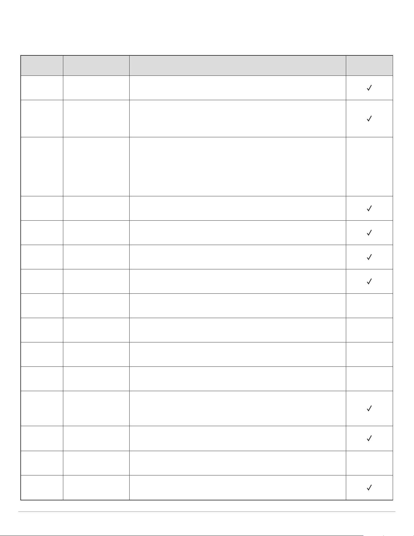
Combo Views
Combo views display two views (or more) on the screen at the same time. To change the settings, select menus or actions, or
change the size of either view, you must select the view as the Active Pane from the X-Press menu. The available combo views are
determined by your Humminbird model.
Selecting an Active Pane of the Down/Sonar Combo View
Sonar X-Press Menu
indicates the selected
pane (Active Pane)
split position
adjusts pane size
split position
adjusts pane size
Down X-Press Menu
Select an Active Pane
To change the settings in a combo view, or to use the cursor on a view, the individual view must be selected as the active pane.
1. X-Press Menu: With a Combo View displayed on-screen, press the MENU key once.
2. Select Active Pane.
3. Select a pane.
X-Press Menu: The X-Press Menu updates with the menus available for the active pane of the view.
Cursor: Press any arrow on the Cursor Control key to use the cursor on the active pane of the view.
Adjust the View Pane Size
Split Position allows you to adjust the size of the selected pane in a Combo View.
1. X-Press Menu: With a Combo View displayed on-screen, press the MENU key once.
2. Select Split Position.
3. Press the RIGHT or LEFT Cursor keys to adjust the pane size.

39
Set up Sonar
Set up Sonar
The available sonar views and menus on the control head are determined by the connected transducer and the selected transducer
source.
Most of the settings in this section were set up when you first powered on the unit using the Quick Setup Menu. Use
the instructions in this section to adjust those settings, set up an accessory transducer, or refine the information
shown on-screen.
Set up an Accessory Transducer
(Optional)
The control head will automatically select the transducer that was included with your control head. If your model is compatible with
an accessory transducer, and it is connected to the control head, select the transducer in the system so the beams are activated
and the related views are added to the control head. See Getting Started: Quick Setup for more information.
NOTE: For more information about accessory transducers, download the Transducer Compatability Guide and the Transducer
Resource Guide from our Web site at humminbird.com.
1. Main Menu: Press the MENU key twice. Select the Sonar tab.
2. Select Connected Transducer.
3. Select the transducer connected to the unit.
To reselect your control head’s default transducer, press and hold the LEFT Cursor key to select the first transducer listed.
To adjust the depth offset, see Manage your Control Head.
Adjust the Noise Filter (Optional)
If interference appears on the sonar views from sources such as your boat engine, turbulence, or other sonar devices, use Noise
Filter to limit the interference.
1. Main Menu (Custom User Mode): Press the MENU key twice. Select the Sonar tab.
2. Select Noise Filter.
3. Select a filter setting, where 1 is the lightest filter and 4 filters the most interference.
Off: removes all filtering.
Higher settings are useful when there is excessive trolling motor noise. However, in some deep water situations, higher settings
may hinder the control head’s ability to find the bottom.
Change the Max Depth (Optional)
The Max Depth was set when you first configured the unit with the Quick Setup dialog box (see Getting Started: Quick Setup). Use
the instructions in this section to adjust the maximum depth setting.
1. Main Menu (Custom User Mode): Press the MENU key twice. Select the Sonar tab.
2. Select Max Depth.
3. Select one of the following:
Auto: the control head will acquire bottom readings as needed (within the capabilities of the unit).
Set to match the body of water depth: the control head will not attempt to acquire sonar data below that depth, so more detail
will be shown on the display.
NOTE: Side Imaging units default to the Side Imaging range setting if the SI Range is set deeper than the Max Depth. See the Side
Imaging section for more information.

40
Set up Sonar
Select the Digital Depth Source
Depending on the depth, the control head will automatically choose the 2D conical beams or the Down Imaging beams to display
the depth digital readout. If the depth is deeper than 350 ft, or if you connect an ice transducer to the control head, set the Digital
Depth Source to 2D Element.
NOTE: Selecting the Digital Depth Source is available on the following models: DI, CHIRP DI, CHIRP MEGA DI, CHIRP MEGA DI+,
CHIRP MEGA SI, and CHIRP MEGA SI+.
1. Main Menu (Custom User Mode): Press the MENU key twice. Select the Sonar tab.
2. Select Digital Depth Source.
3. Select Auto or 2D Element.
Auto: The control head will acquire the digital depth as needed.
2D Element: Select 2D Element if the depth is deeper than 350 feet. Down Imaging is not available with this setting.
Turn on Max DI (CHIRP MEGA SI models only)
Max DI (On) is typically used for deep water to provide the maximum strength for the Down Imaging signal. Max DI (Off) typically
provides the best resolution in shallow water.
1. Main Menu (Custom User Mode): Press the MENU key twice. Select the Sonar tab.
2. Select Max DI.
3. Select On or Off.
Change DI Frequency Presets (CHIRP MEGA DI+ and CHIRP MEGA SI+ models only)
Increased Range is typically used for deep water to provide the maximum strength for the Down Imaging signal. Increased Detail
typically provides the best resolution in shallow water.
1. Main Menu (Custom User Mode): Press the MENU key twice. Select the Sonar tab.
2. Select DI Frequency.
3. Select Increased Detail (default) or Increased Range.
Change the Water Type
The Water Type was set when you first configured the unit with the Quick Setup dialog box (see Getting Started: Quick Setup). Water
Type affects the accuracy of deep water depth readings and configures the control head for operation in fresh or salt water. Use
the instructions in this section to change the Water Type setting.
1. Main Menu (Custom User Mode): Press the MENU key twice. Select the Sonar tab.
2. Select Water Type.
3. Select one of the following for your water type and depth conditions:
Fresh
Salt (shallow)
Salt (deep): If the depth is more than 330 ft (100 m), select Salt (deep).

41
Set up Sonar
Change the Side Imaging Orientation (CHIRP MEGA SI, CHIRP MEGA SI+ models only)
Use SI Orientation to switch how the Side Imaging beams are displayed in the Side Imaging View. This menu option can be used if
the port and starboard beams are reversed during installation, which might be the case if a transducer is installed incorrectly. For
further assistance, contact Humminbird Technical Support.
1. Main Menu (Custom User Mode): Press the MENU key twice. Select the Sonar tab.
2. Select SI Orientation
3. Select Normal or Reverse.
Set up Ice Fishing
(ICE HELIX CHIRP, HELIX 5 and 7 G2/G2N, HELIX 7 G3 and HELIX 7, 8, 9 and 10 G3N models only)
If you have a compatible CHIRP model and want to use it for ice fishing, Ice Fishing mode must be turned on. See Ice Fishing
Overview: Turn on Ice Fishing Mode for more information.
Turn o Sonar
If you’re using your control head for GPS/Navigation functions only, use these instructions to hide all sonar views from the view
rotation. When it is set to Off, this setting also stops the unit from pinging, so all sonar operation is deactivated.
1. Press the POWER key.
2. Select Sonar.
3. Select Off.
NOTE: You can also turn on/off Sonar from the Main Menu > Setup tab > Sonar.
Turn on/o CHIRP (optional, CHIRP models only)
To use CHIRP sonar, CHIRP mode must be turned on. The menu options are determined by the installed transducer and control
head model.
NOTE: Humminbird has provided the best settings for your unit. You can use the settings included with your control head, or you
can adjust these advanced options.
Turn on/off 2D CHIRP
1. Main Menu (Custom User Mode): Press the MENU key twice. Select the Setup tab.
2. Select CHIRP Configuration. Press the RIGHT Cursor key.
If the menu is not shown in the Setup tab, select the Sonar tab.
3. Select 2D CHIRP Mode.
4. Select On or Off. (Default = On)
Turn on/off Down Imaging CHIRP
1. Main Menu (Custom User Mode): Press the MENU key twice. Select the Setup tab.
2. Select CHIRP Configuration.
3. Select DI CHIRP Mode or Imaging CHIRP Mode. Press the RIGHT Cursor key.
4. Select On or Off. (Default = On)
42
Set up Sonar
Turn on/off Side Imaging CHIRP
1. Main Menu (Custom User Mode): Press the MENU key twice. Select the Setup tab.
2. Select CHIRP Configuration. Press the RIGHT Cursor key.
3. Select SI CHIRP Mode or Imaging CHIRP Mode.
4. Select On or Off. (Default = On)
Select Frequencies for the 2D Sonar View (optional)
Use the instructions in this section to select the frequencies that will be used for the 2D Sonar views. The menu options are
determined by the installed transducer and control head model.
NOTE: You can also change the frequency in the 2D Sonar View while you fish by pressing the CHECK key (see the 2D Sonar View
section: Adjust Settings While you Fish).
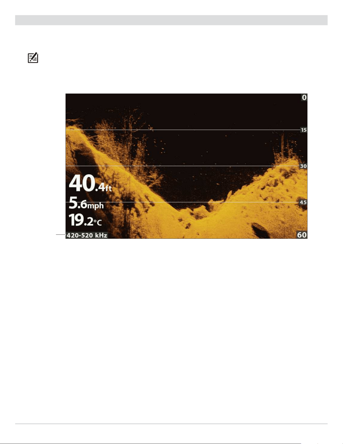
Display Frequency for the 2D Sonar View (HELIX 7 CHIRP GPS G2)
frequency
label
Select Frequencies for the (2D) Sonar View
1. Main Menu: Press the MENU key twice. Select the Sonar tab.
2. Select 2D Display Frequency.
Dual Beam CHIRP Models: Select 2D CHIRP Display Frequency.
Dual Spectrum CHIRP Models: Select Display Spectrum.
3. Select a frequency.
For details, see the tables in Understand Transducer Frequencies and refer to your transducer model.
43
Set up Sonar
Select a Frequency for the Down Imaging View (optional)
Use the instructions in this section to choose a frequency that will be used for the Down Imaging View. The menu options are
determined by the installed transducer and control head model.
NOTE: You can also change the frequency in the Down Imaging View while you fish by pressing the CHECK key (see the Down
Imaging section: Adjust Settings While you Fish).
Display Frequency for the Down Imaging View (HELIX 9 CHIRP DI GPS G2N)
frequency
label
Select a Frequency for the Down Imaging View
1. Main Menu: Press the MENU key twice. Select the Sonar tab.
2. DI Models: Select Imaging Display Frequency.
CHIRP DI, CHIRP MEGA, CHIRP MEGA+ Models: Select DI CHIRP Display Frequency.
3. Select a frequency.
For details, see the tables in Understand Transducer Frequencies and refer to your transducer model.
44
Set up Sonar
Set the Down Imaging Beam Width (optional, XNT 9 SI 180 T only)
If the XNT 9 SI 180 T (Compact Side Imaging transducer) is installed, you can set the width of the beam (side to side) used for the
Down Imaging View. To see only the data directly under your boat, select Narrow. Medium reveals more information, while Wide
displays the maximum information available from the Down Imaging beam width. See Understand the Down Imaging View for more
information.
1. Main Menu (Custom User Mode): Press the MENU key twice. Select the Sonar tab.
2. Select Down Imaging Beam Width.
3. Press the RIGHT or LEFT Cursor keys to select a width.
Select a Frequency for the Side Imaging View (optional, CHIRP MEGA SI, CHIRP MEGA SI+ models only)
Use the instructions in this section to choose a frequency that will be used for the Side Imaging View.
NOTE: You can also change the frequency in the Side Imaging View while you fish by pressing the CHECK key (see the Side Imaging
section: Adjust Settings While you Fish).
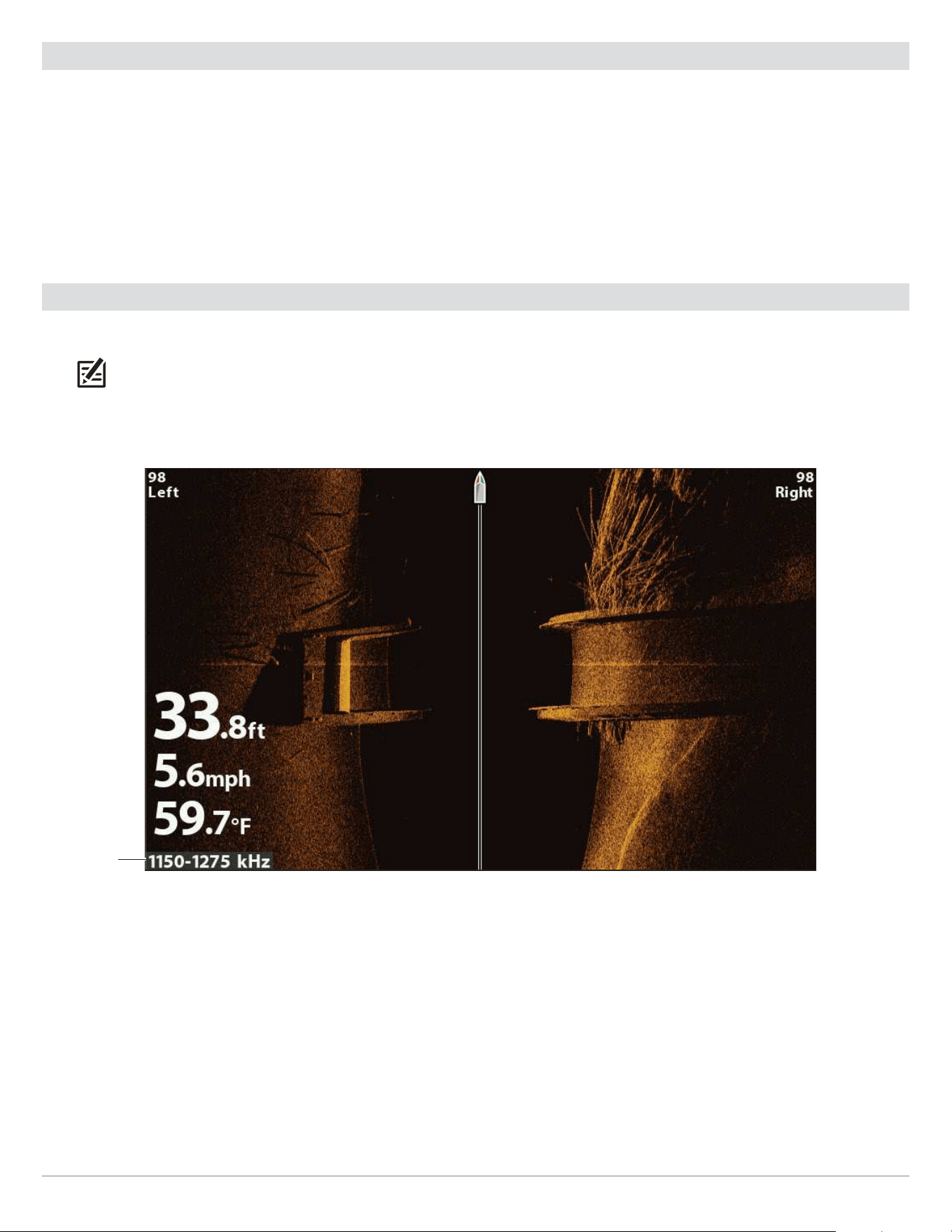
Display Frequency for the Side Imaging View (CHIRP MEGA SI)
(HELIX 9 CHIRP SI GPS G2N)
frequency
label
Select a Frequency for the Side Imaging View
1. Main Menu: Press the MENU key twice. Select the Sonar tab.
2. Select SI CHIRP Display Frequency.
3. Select a frequency.
For details, see the tables in Understand Transducer Frequencies and refer to your transducer model.
45
Set up Sonar
Understand Transducer Frequencies
High Wide Transducers
2D Models
XNT 9 HW T
XNT 9 HW
XP 9 HW T
XP 9 HW
XTM 9 HW T
XPTH 9 HW T
XPT 9 HW T
DI Models
XNT 9 HW DI T
MEGA DI Models
XNT 9 MDI T
XNT 9 HW MDI 75 T
XNM 9 HW MDI 75 T
MEGA DI+ Models
XM 9 HW MDI T
XTM 9 HW MDI T
SI Models
XNT 9 HW SI T
MEGA SI Models
XNT 9 HW MSI 150 T
XTM 9 HW MSI 150 T
MEGA SI+ Models
XM 9 HW MSI T
XT M 9 HW MSI T
XPTH 9 HW MSI T
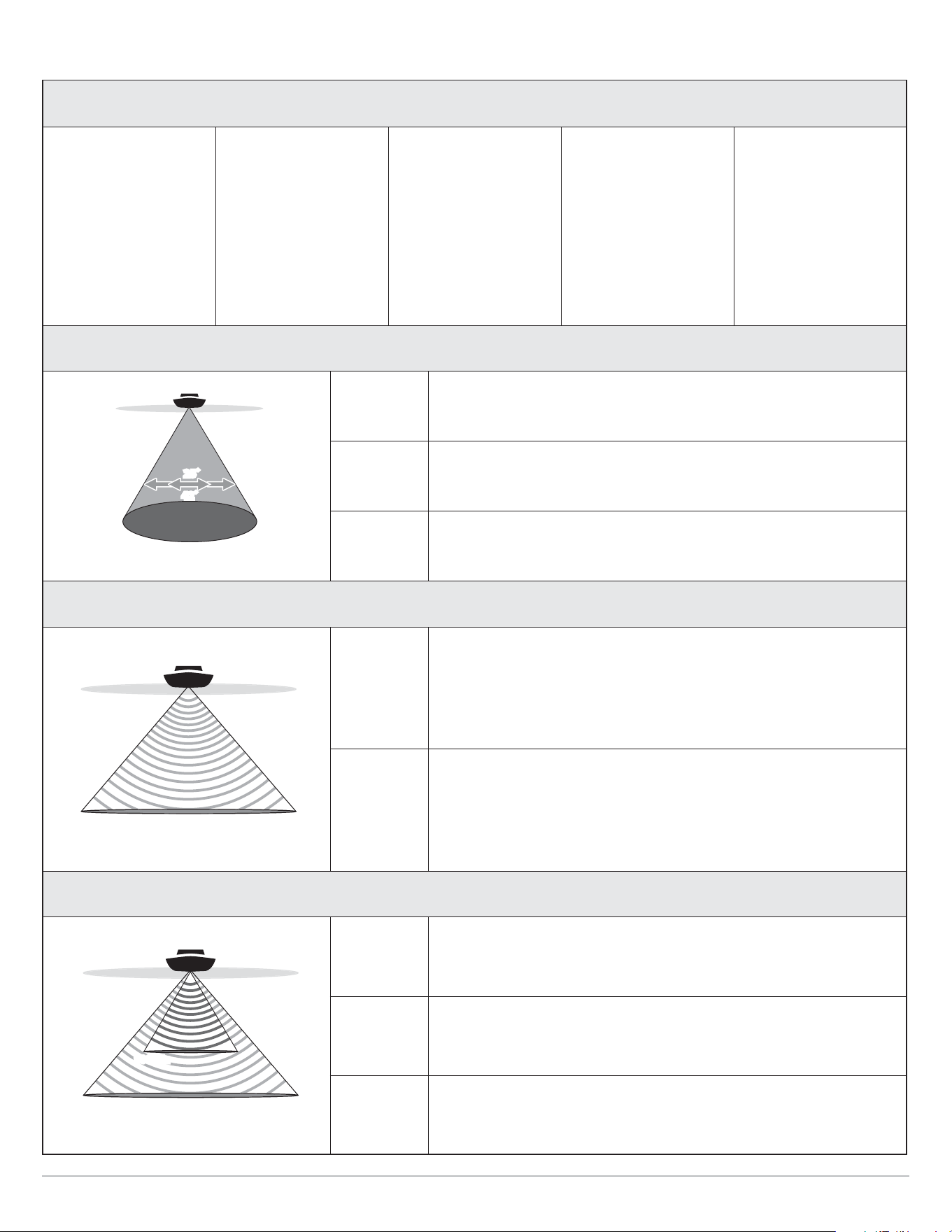
2D Display
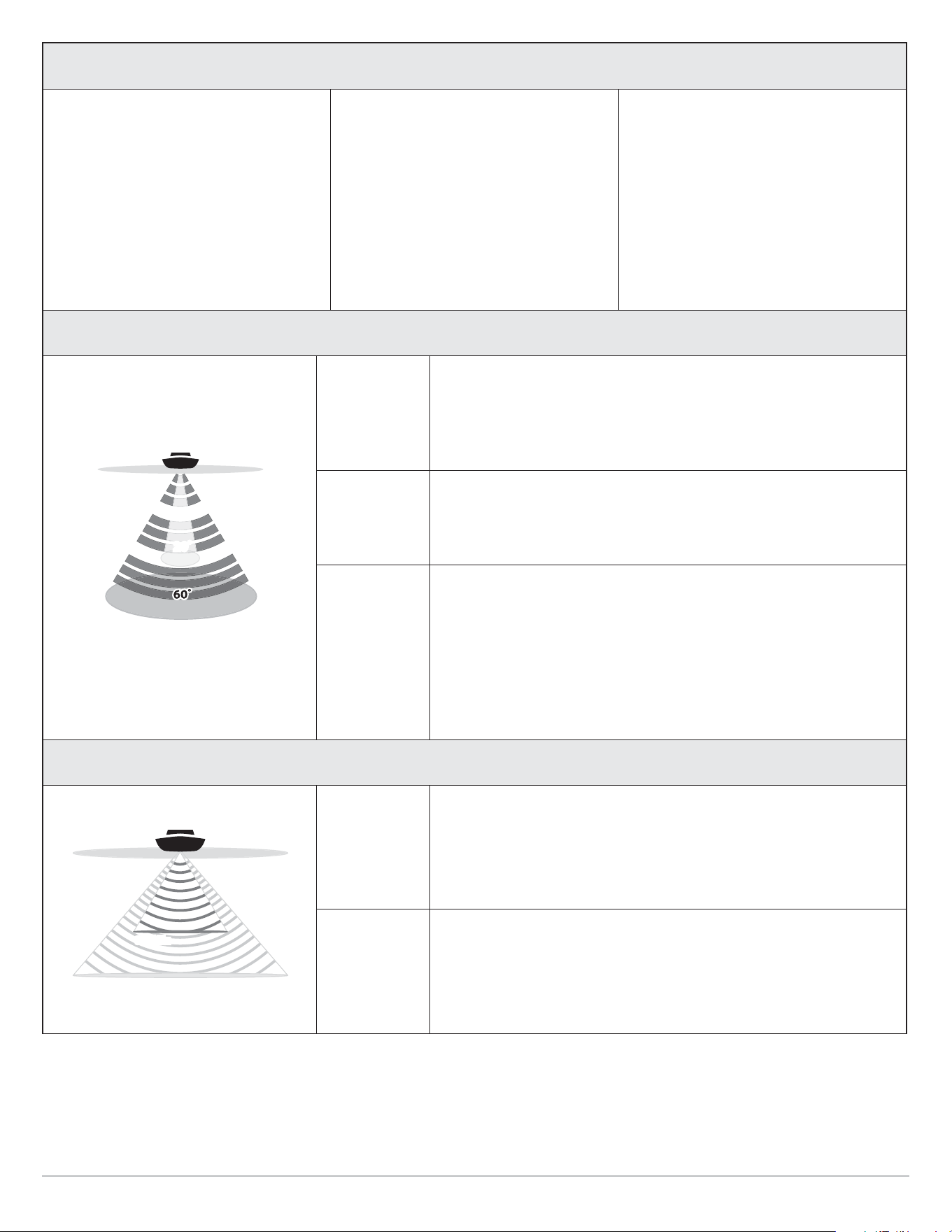
Full Select Full Beam (default) to use the complete frequency range.
Narrow
Select Narrow Beam for increased bottom detail and better target
separation.
Wide
Select Wide Beam to maximize coverage and show big, clearly
defined fish arches.
DI Display
MEGA
(MDI
models
only)
Select MEGA for the highest resolution, sharpness, and depth (up
to 125 ft).
*For MEGA SI models, the range is up to 75 ft.
455 kHz
Select 455 kHz for deep water and overall coverage (up to 400 ft
for DI models and MDI models).
DI+ Display
MEGA+
Select MEGA for the highest resolution, sharpness, and depth (up
to 200 ft).
800 kHz
Select 800 kHz as an alternative frequency with sharp returns (up
to 125 ft).
455 kHz Select 455 kHz for deep water and overall coverage (up to 400 ft).
25˚
42˚
Dual Spectrum Cone Angles
75°
75°
455kHz/
MEGA
75°
DI and MEGA DI Cone Angles
75°
75°
455kHz/
MEGA+
75°
800kHz
45°
45°
45°
MEGA DI+ Cone Angles
46
Set up Sonar
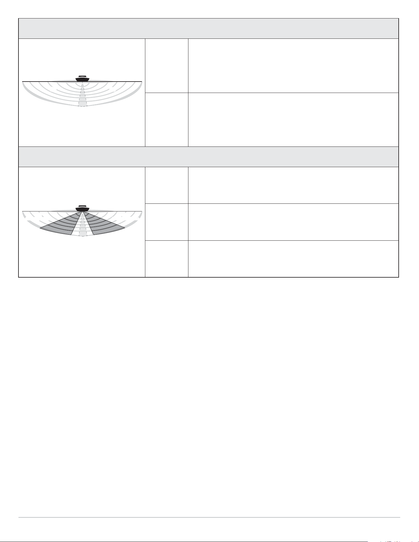
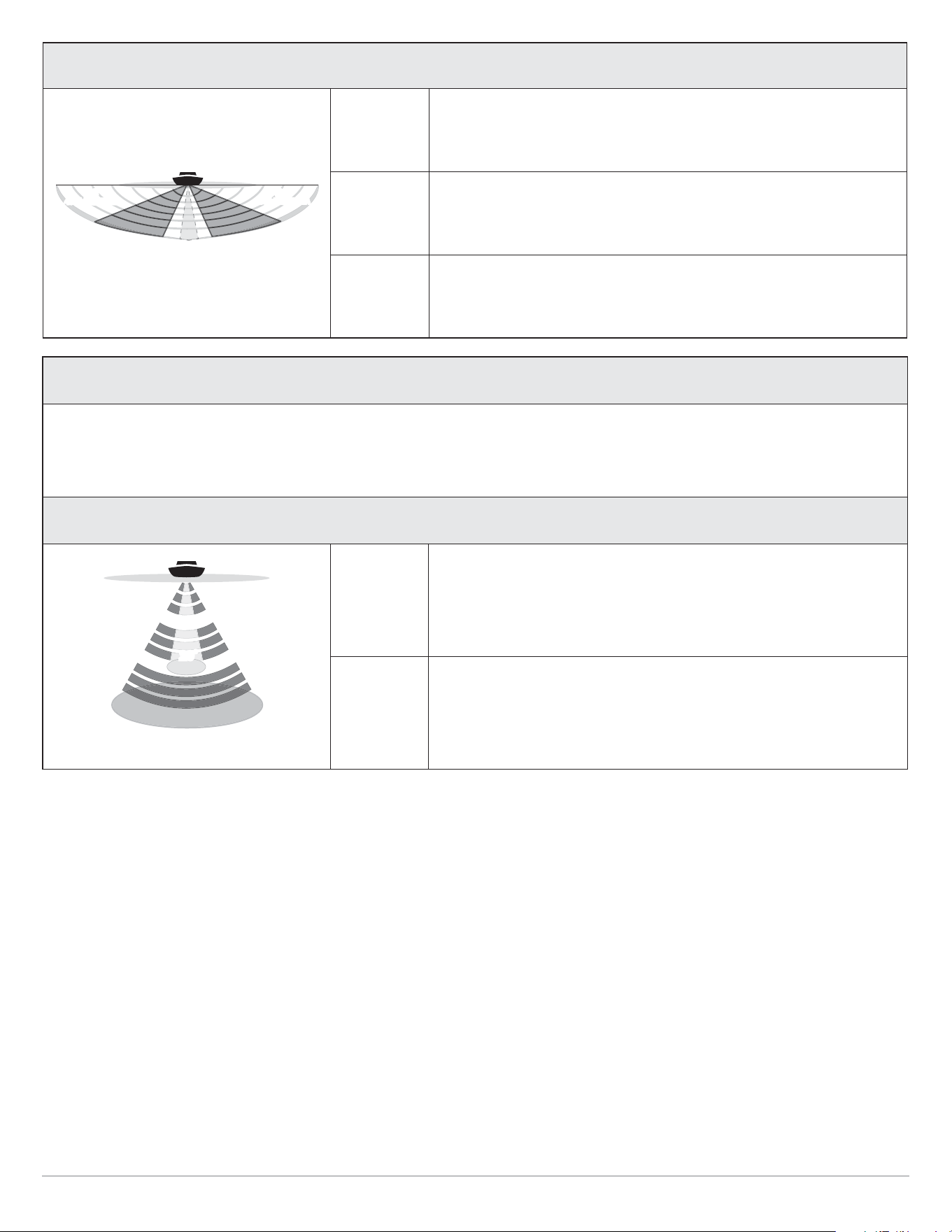
SI Display
MEGA
(MSI
models
only)
Select MEGA for the highest resolution, sharpness, and range (up
to 250 ft side to side).
455 kHz
Select 455 kHz for deep water and overall coverage (up to 250
ft side to side for SI models and up to 800 ft side to side for MSI
models).
SI+ Display
MEGA+
Select MEGA for the highest resolution, sharpness, and range (up
to 400 ft side to side).
800 kHz
Select 800 kHz as an alternative frequency with sharp returns (up
to 250 ft side to side).
455 kHz
Select 455 kHz for deep water and overall coverage (up to 800 ft
side to side).
455kHz/MEGA
455kHz/MEGA
455kHz/MEGA
455kHz/MEGA
86
˚8
6˚
455kHz/MEGA455kHz/MEGA
SI and MEGA SI Cone Angles
86˚
86˚
455kHz/MEGA+
455kHz/MEGA+
455kHz/MEGA+
455kHz/MEGA+
800kHz
800kHz
45˚
45
˚
45˚
45
˚
800kHz
800kHz
800kHz
45˚
800kHz
45˚
MEGA SI+ Cone Angles
47
Set up Sonar
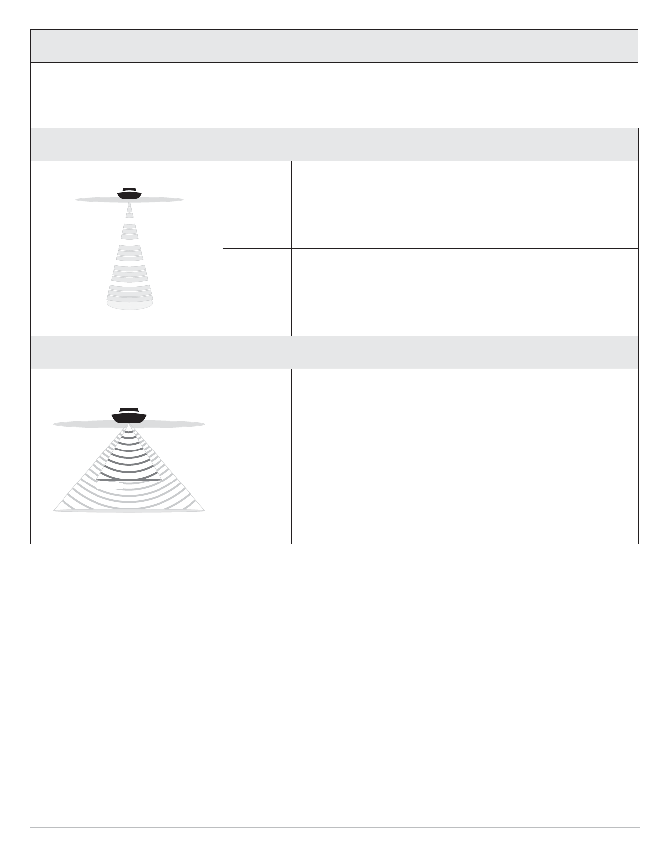
83/200 kHz Transducers
2D Models
XNT 9 20 T
XNT 9 20
XP 9 20 T
XP 9 20
XTM 9 20 T
XPTH 9 20 T
XPT 9 20 T
XAP 9 20
DI Models
XTM 9 WIDE DI 20 T
SI Models
XNT 9 SI 180 T
XTM 9 SI 180 T
XHS 9 HDSI 180 T
XTM 9 HDSI 180 T
XPTH 9 HDSI 180 T
XM 9 20 MSI T
XTM 9 20 MSI T
XPTH 9 20 MSI T
2D Display
Medium
(83 kHz)
Frequency
Select Medium Frequency for deep water (more than 800 feet).
Medium Frequency can be used for deep returns at high speed. If
Medium Frequency is selected, the high frequency beam pings in the
background but is not displayed.
High
(200 kHz)
Frequency
Select High Frequency for more detail at shallower depths (less than
800 feet). If High Frequency is selected, the medium frequency beam
is not available.
Medium/
High
(83/200 kHz)
Frequency
Select Medium/High Frequency to ensure both beams ping
continuously, so the sonar history is not interrupted if the Sonar
View is closed.
The returns from both beams are blended by starting with the wide
beam return, dimming it, and then overlaying it with the narrow
beam return. The narrow beam sonar returns will stand out from
the wide beam sonar returns.
DI Display
455 kHz
(CHIRP)
Select 455 kHz CHIRP for greater bottom coverage in deep water (up
to 350 feet).
800 kHz
(CHIRP)
Select 800 kHz CHIRP for shallow water and the sharpest image.
83kHz
83kHz
83kHz
200kHz
20˚
DualBeam Cone Angles
75°
75°
455kHz
75°
800kHz
45°
45°
45°
DI Cone Angles
48
Set up Sonar
SI Display
MEGA
(CHIRP)
Select MEGA CHIRP for the highest resolution, sharpness, and
range (up to 250 ft side to side).
800 kHz
(CHIRP)
Select 800 kHz CHIRP as an alternative frequency with sharp
returns (up to 250 ft side to side).
455 kHz
(CHIRP)
Select 455 kHz CHIRP for deep water and overall coverage (up to
800 ft side to side).
86˚
86˚
455kHz/MEGA
455kHz/MEGA
455kHz/MEGA
455kHz/MEGA
800kHz
800kHz
45
˚
45
˚
45
˚
45
˚
800kHz
800kHz
800kHz
45
˚
800kHz
45
˚
SI Cone Angles
50/200 kHz Transducers
Models
XNT 9 DB 74 T
XTH 9 DB 74 P
2D Display
50 kHz
(Low)
Select 50 kHz for deep water (more than 1500 feet). 50 kHz can be
used for deep returns at high speed. If 50 kHz is selected, the 200
kHz beam pings in the background but is not displayed.
200 kHz
(High)
Select 200 kHz for faster pinging and shallower water (less than
800 feet).
200kHz
74˚
74˚
50kHz
50kHz
50kHz
20˚
74˚
50/200 kHz Cone Angle
49
Set up Sonar
200/455 kHz Transducers
Models
XNT 9 DI T
XTM 9 SI 25 T
2D Display
High
(200 kHz)
Select High Frequency for greater bottom coverage in deep water
(up to 600 feet).
High
(455 kHz)
Select High (455 kHz) Frequency for shallow water (up to 350 feet).
DI Display
455 kHz
Select 455 kHz for greater bottom coverage in deep water (up to 350
feet).
800 kHz Select 800 kHz for shallow water and the sharpest image.
200kHz
28°
2D Cone Angles
75°
75°
455kHz
75°
800kHz
45°
45°
45°
DI Cone Angles

50
Set up Sonar
Adjust the CHIRP Frequency Spectrum (optional, CHIRP models only)
Your control head has been configured with the best settings for a wide range of fishing conditions, and we recommend using the
default start and end CHIRP frequency spectrum included with your unit. However, you can adjust the CHIRP Frequency Spectrum
to limit the interferences on the display or refine the settings to your preference. The menu options are determined by the installed
transducer and control head model.
Requirements: CHIRP mode must be turned on. The menus are also determined by the display frequency you have selected for
each view.
WARNING! If an accessory transducer is installed, confirm it is configured in the control head. See Set up an Accessory Transducer
for details. For information about accessory transducers, visit our Web site at humminbird.com.
Adjust the 2D CHIRP Frequency Spectrum
1. Main Menu (Custom User Mode): Press the MENU key twice. Select the Setup tab.
2. Select CHIRP Configuration. Press the RIGHT Cursor key.
If the menu is not shown in the Setup tab, select the Sonar tab.
3. Select 2D CHIRP Frequency Spectrum. Press the RIGHT Cursor key.
4. Select a frequency menu.
5. Press the RIGHT or LEFT Cursor keys to select a setting.
6. Repeat: Repeat steps 4 and 5 to adjust the Start Frequency and End Frequency for each beam.
7. Close: Press the EXIT key.
Adjust the Down Imaging CHIRP Frequency Spectrum
1. Main Menu (Custom User Mode): Press the MENU key twice. Select the Setup tab.
2. Select CHIRP Configuration. Press the RIGHT Cursor key.
If the menu is not shown in the Setup tab, select the Sonar tab.
3. Select DI CHIRP Frequency Spectrum or Imaging CHIRP Frequency Spectrum. Press the RIGHT Cursor key.
4. Select a frequency menu.
5. Press the RIGHT or LEFT Cursor keys to select a setting.
6. Repeat: Repeat steps 4 and 5 to adjust the Start Frequency and End Frequency for each beam.
7. Close the Submenu: Press the EXIT key.
Adjust the Side Imaging CHIRP Frequency Spectrum
1. Main Menu (Custom User Mode): Press the MENU key twice. Select the Setup tab.
2. Select CHIRP Configuration. Press the RIGHT Cursor key.
If the menu is not shown in the Setup tab, select the Sonar tab.
3. Select SI CHIRP Frequency Spectrum. Press the RIGHT Cursor key.
4. Select a frequency menu.
5. Press the RIGHT or LEFT Cursor keys to select a setting.
6. Repeat: Repeat steps 4 and 5 to adjust the Start Frequency and End Frequency for each beam.
7. Close the Submenu: Press the EXIT key.

51
Set up Sonar
Reset CHIRP Configuration Settings
Use the following instructions to reset the CHIRP menu settings to the factory defaults.
1. Main Menu (Custom User Mode): Press the MENU key twice. Select the Setup tab.
2. Select CHIRP Configuration. Press the RIGHT Cursor key.
3. Select Local CHIRP Configuration Reset. Press the RIGHT Cursor key.
52
Sonar (2D)
Display a Sonar View On-Screen
There are a variety of views available to display sonar data. You can customize the view by showing or hiding information (see
Customize the Sonar View), and you can adjust the sonar settings to refine the information displayed on-screen (see Adjust Sonar
Display Settings and Adjust Settings While you Fish). The changes you make are applied to all traditional 2D sonar views.
Display a Sonar View
1. Press and hold the VIEW key.
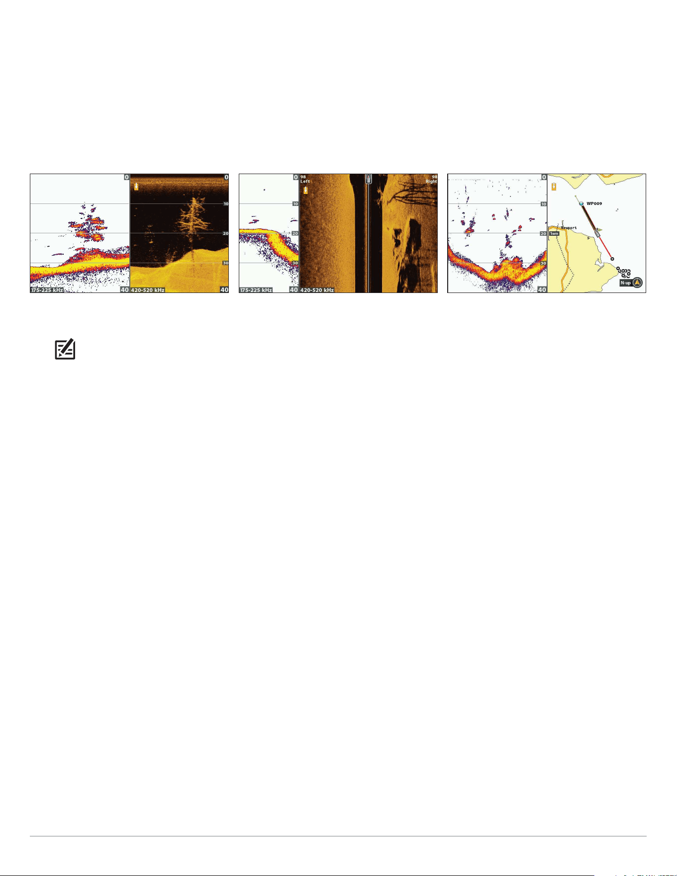
2. Select Sonar > Sonar View, Sonar Zoom View, Split Sonar View, etc.
Split Sonar View
For more information, see
Compare Sonar Beams.
Sonar Zoom View
For more information, see
Review Sonar History and Zoom In/Zoom Out.
Sonar View
Flasher View (ICE HELIX CHIRP)
For more information, see
Display the Flasher View On-Screen.
Big Digits View
NOTE: The available views are determined by your control head model and the installed transducer. For a complete list of the
views available on your control head, press the MENU key twice, and select the Views tab. See each related section of the manual
(Views, Down Imaging, Side Imaging, Navigation Overview, etc.) for more information.
53
Sonar (2D)
Display a Sonar Combo View
1. Press and hold the VIEW key.
2. To open a Sonar Combo View, select Sonar.
To open a Chart Combo View (Sonar and Chart together), select Chart.
3. Select a view to display on-screen.
Chart > Chart/Sonar Combo View
(Map Source: Contour XD)
For more information, see Navigation Overview.
Sonar > Side/Sonar Combo View
For more information, see the Side Imaging section.
Sonar > Down/Sonar Combo View
For more information, see the Down Imaging section.
NOTE: The available views are determined by your control head model and the installed transducer. For a complete list of the
views available on your control head, press the MENU key twice, and select the Views tab. See each related section of the manual
(Views, Down Imaging, Side Imaging, Navigation Overview, etc.) for more information.
54
Sonar (2D)
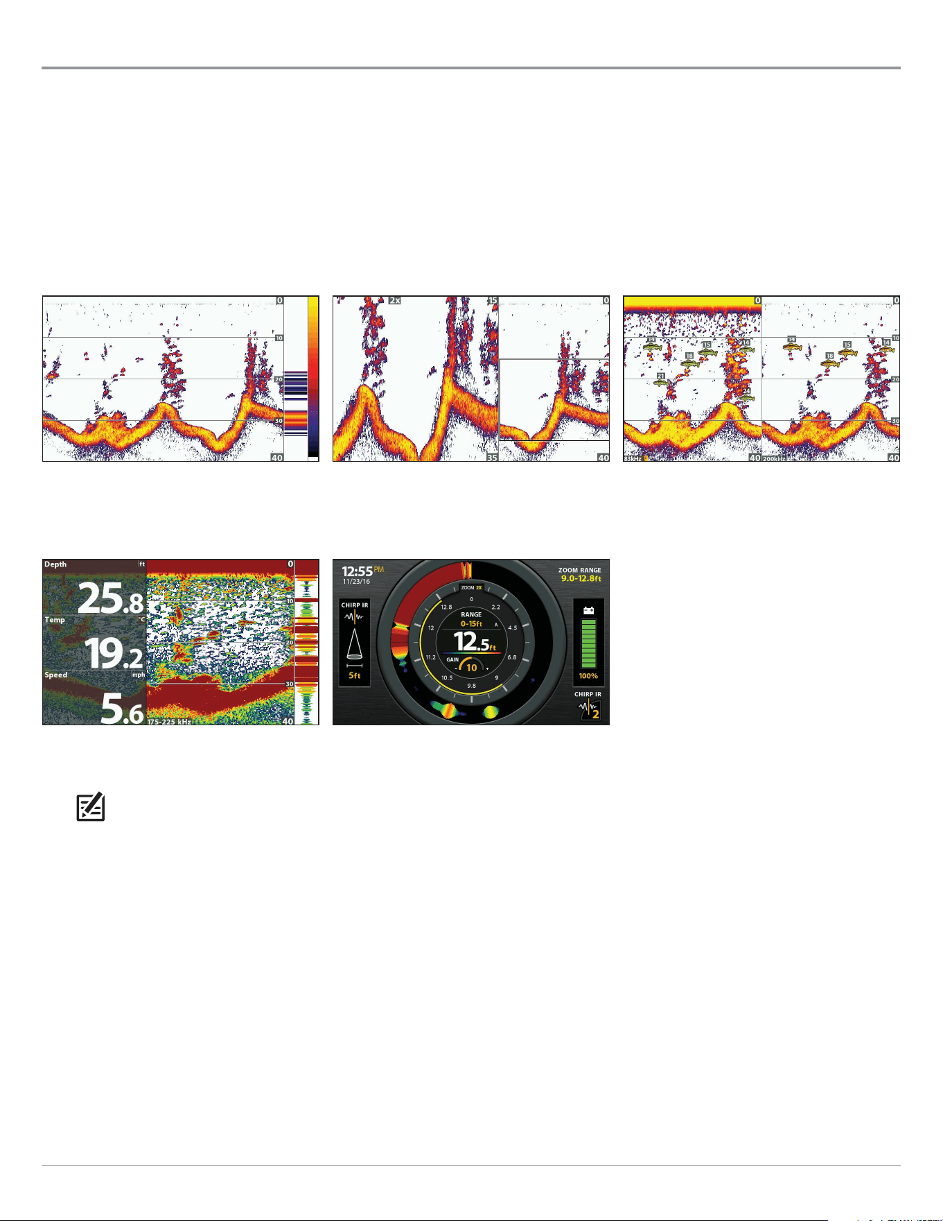
Understand the Sonar Views
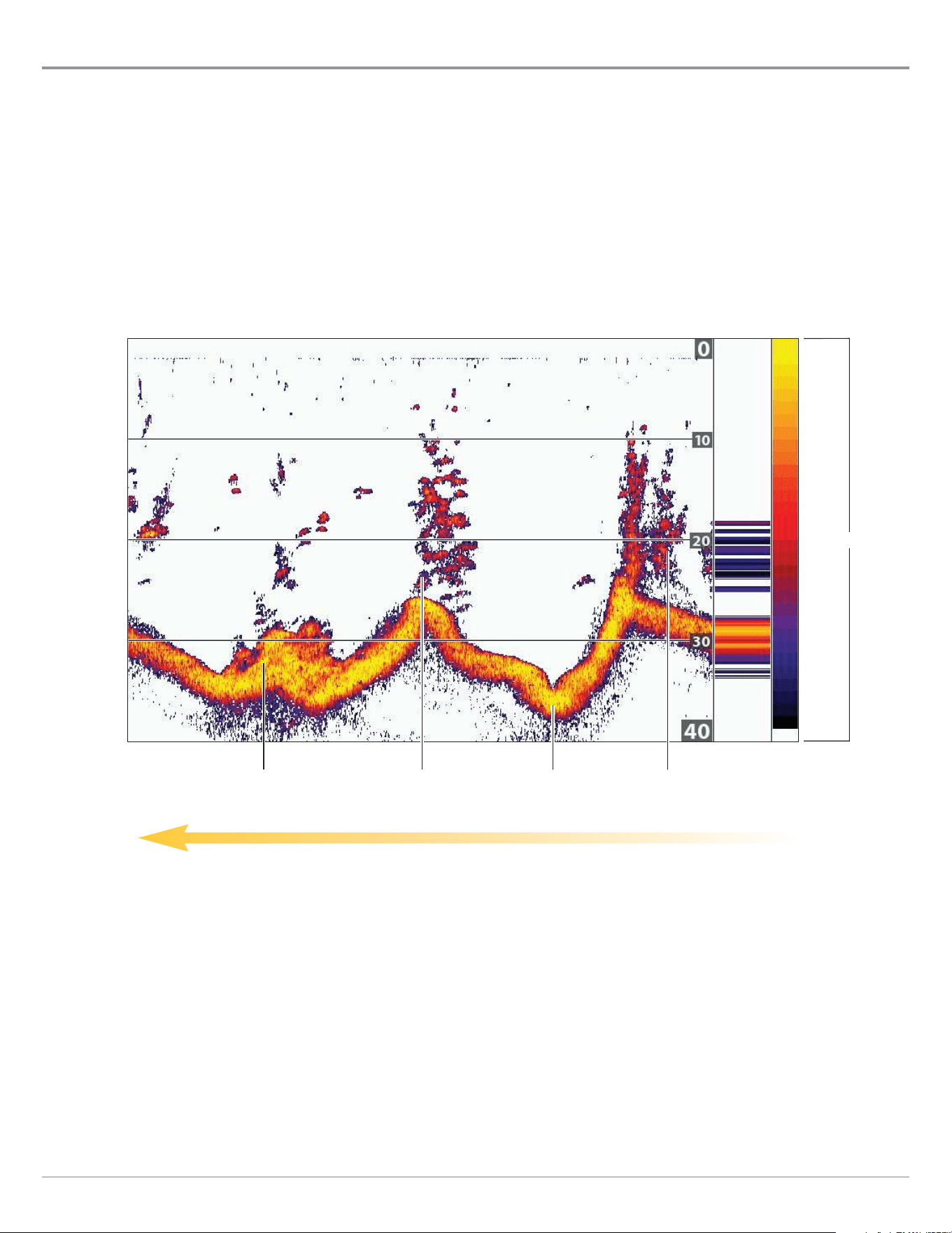
As the boat moves, the unit charts the changes in depth on the display to create a profile of the bottom contour. The Sonar View
displays the sonar return intensity with different colors.
Strong returns often result from rocky or hard bottoms (compacted sediment, rocks, fallen trees), while weaker returns often result
from soft bottoms (sand, mud), vegetation, and small fish.
The colors used to represent high, medium, to low intensity returns are determined by the palette you choose in the Sonar Colors
menu (see Customize the Sonar View).
The control head displays the return intensity based on the Sonar Colors and Bottom View menu settings. You can display the RTS
Window (Real Time Sonar), turn on/off fish symbols (Fish ID+), change the SwitchFire mode, adjust sensitivity, and more.
Sonar History — Historical returns scroll left across the view.
2D Sonar View: Sonar Colors Palette 1
strong returns
(possibly rocks, tree limbs,
or other structure)
weak returns
(possibly vegetation
or small fish)
strong returns
(possibly compacted
sediment or rocks)
medium returns
weak
strong
Color Bar
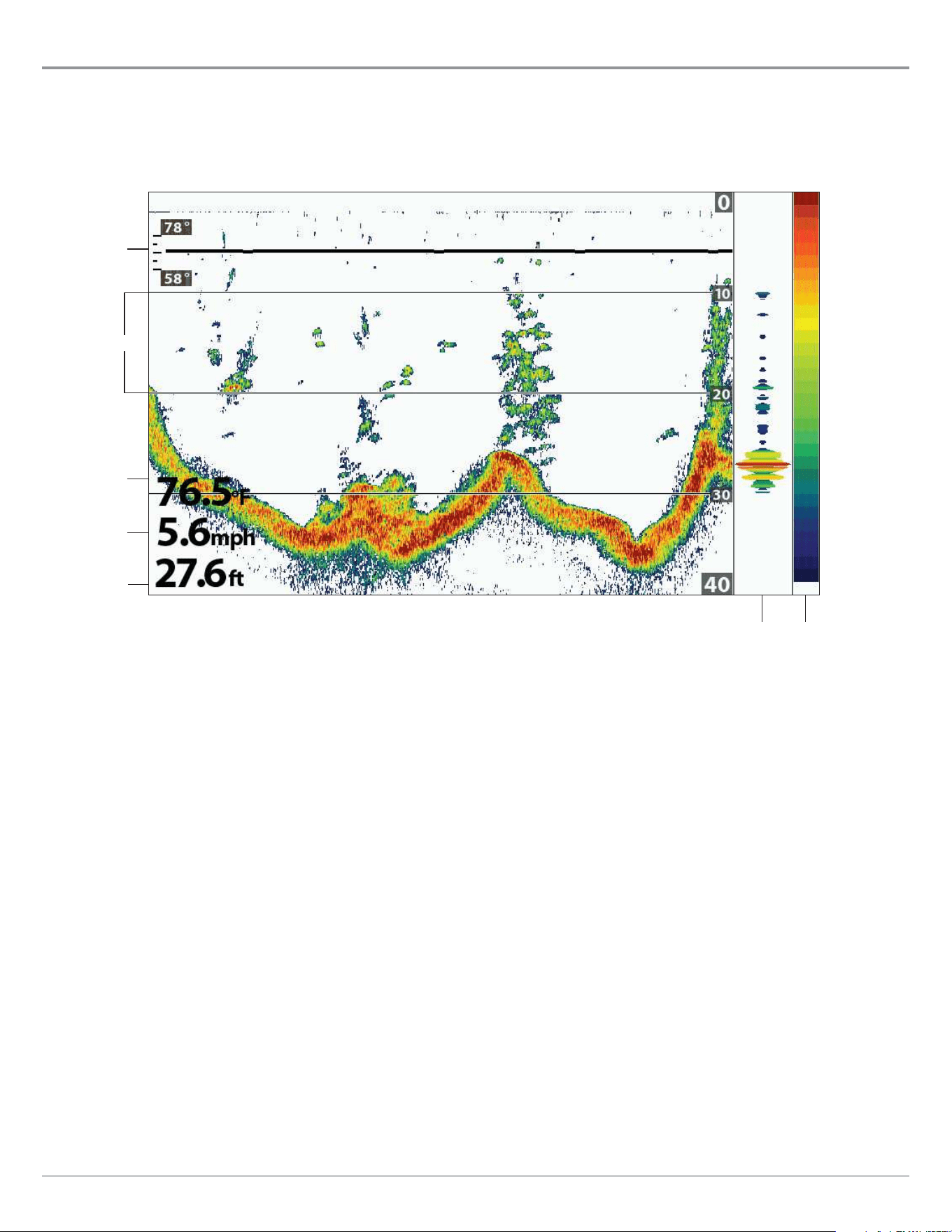
55
Sonar (2D)
Customize the Sonar View
You can customize the sonar views by showing or hiding information, such as the temperature graph, depth lines, color bar, and
RTS Window. You can also change the color palette.
Customizing the Sonar View
temperature
(digital readout
overlay)
depth
(digital readout
overlay)
speed
(digital readout
overlay)
temperature
graph
RTS Window
(A-Scope)
color
bar
depth lines
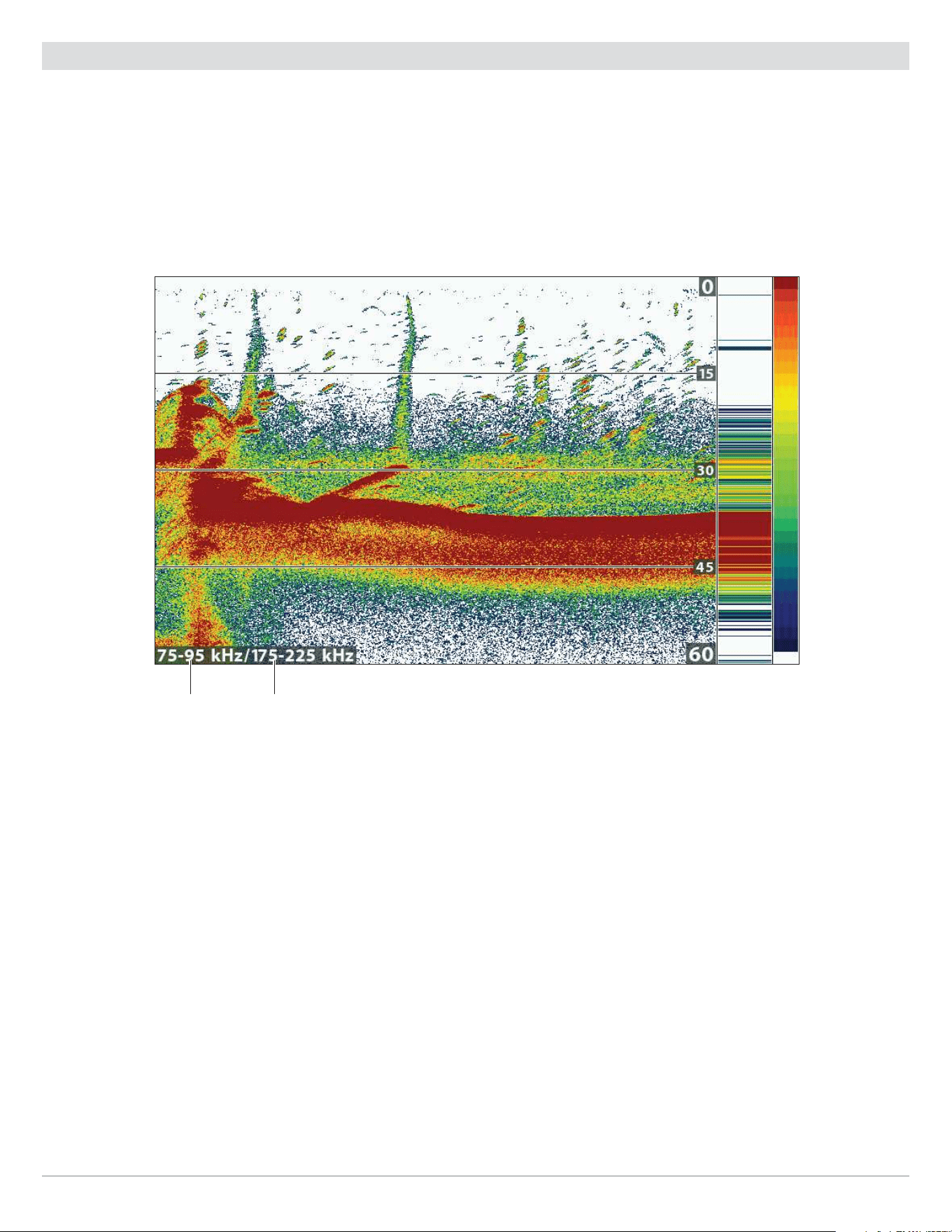
56
Sonar (2D)
Show/Hide the Frequency Label
The Frequency Label displays the currently selected frequencies. See Set up Sonar.
1. Main Menu: Press the MENU key twice. Select the Sonar tab.
2. Select Frequency Label.
3. Select On (show) or Off (hide).
2D Sonar View with Frequency Label Turned On (HELIX 9 CHIRP SI GPS G2N)
selected
display
frequency
selected
frequency
spectrum
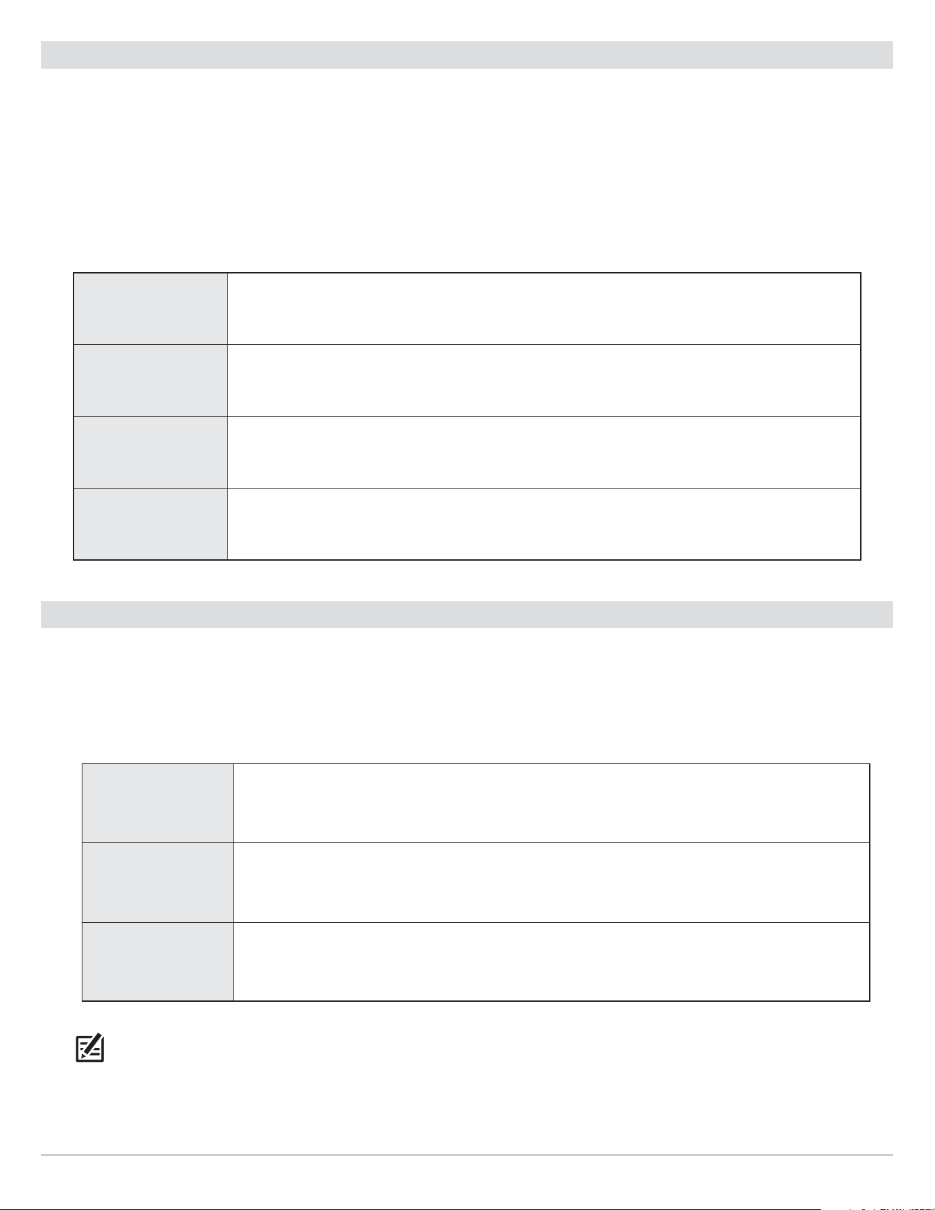
57
Sonar (2D)
Customize the RTS Window
The RTS Window plots the depth and intensity of a sonar return. It updates at the fastest rate possible for depth conditions and
shows only the returns from the bottom, structure, and fish that are within the transducer beam. When you use the cursor to review
sonar history, the sonar history will freeze, but the RTS Window will continue to display sonar returns in real time. See Review Sonar
History and Zoom In/Zoom Out.
1. Main Menu: Press the MENU key twice. Select the Sonar tab.
2. Select RTS Window.
3. Select the type of RTS Window to display.
Mono Sonar returns are displayed in black.
Color (Full) Sonar returns are displayed in color, and they fill the width of the RTS Window.
Color (A-Scope)
Sonar returns are displayed in color. The size of the displayed lines correspond with the
intensity of the sonar returns from the transducer beam(s).
Off The RTS Window is hidden.
Show/Hide Data on the Sonar View
The settings in this section are shared with the Down Imaging View, so turning them on or off will change what is shown on the
Sonar Views and the Down Imaging Views.
1. Main Menu (Custom User Mode): Press the MENU key twice. Select the Sonar tab.
2. Select a menu and change it to On (show) or Off (hide).
Depth Lines
The depth lines show incremental marks between the upper and lower depth range. See Adjust
Sonar Display Settings for details.
Color Bar
The Color Bar shows the palette selected on the Sonar View (see Change the View Colors) from
weak to strong returns.
Temperature
Graph
The temperature graph displays the temperature changes over the recent sonar history. A
temperature input from the installed transducer or temp/speed accessory is required to enable
this feature.
NOTE: Digital readouts can be displayed as an overlay, or they can be displayed in data boxes (see Views: Display Digital
Readouts).
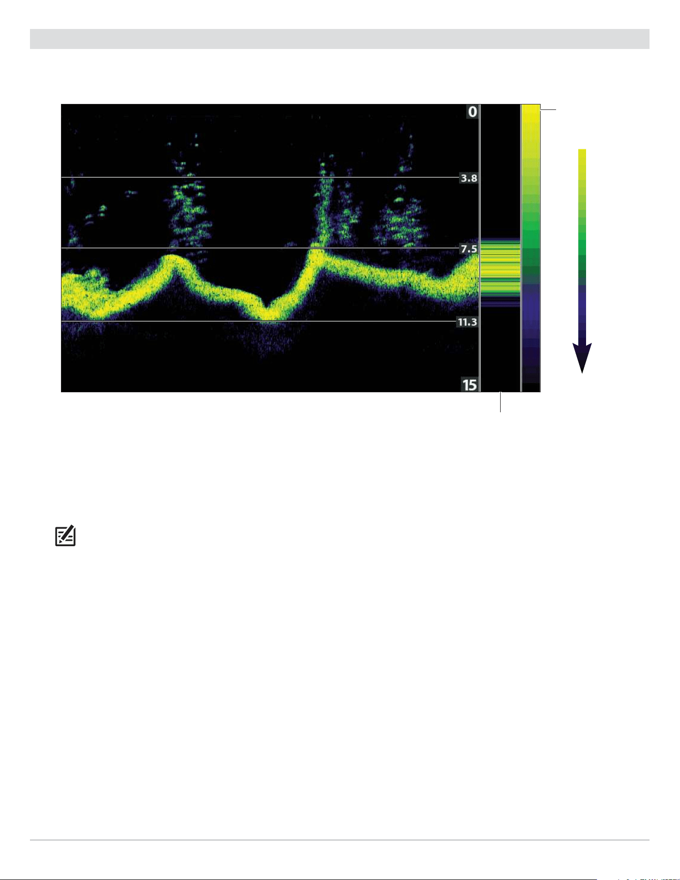
58
Sonar (2D)
Change the View Colors
The Sonar Colors menu changes the colors used to display sonar returns on the view.
RTS Window
Sonar View with Customized Sonar Colors
color bar with
sonar colors set
to palette 4
Weak
Strong
Change the Sonar Colors Palette
1. Sonar X-Press Menu: With a Sonar View displayed on-screen, press the MENU key once.
2. Select Sonar Colors.
3. Select a palette.
NOTE: To display or hide the Color Bar, see
Show/Hide Data on the Sonar View
.
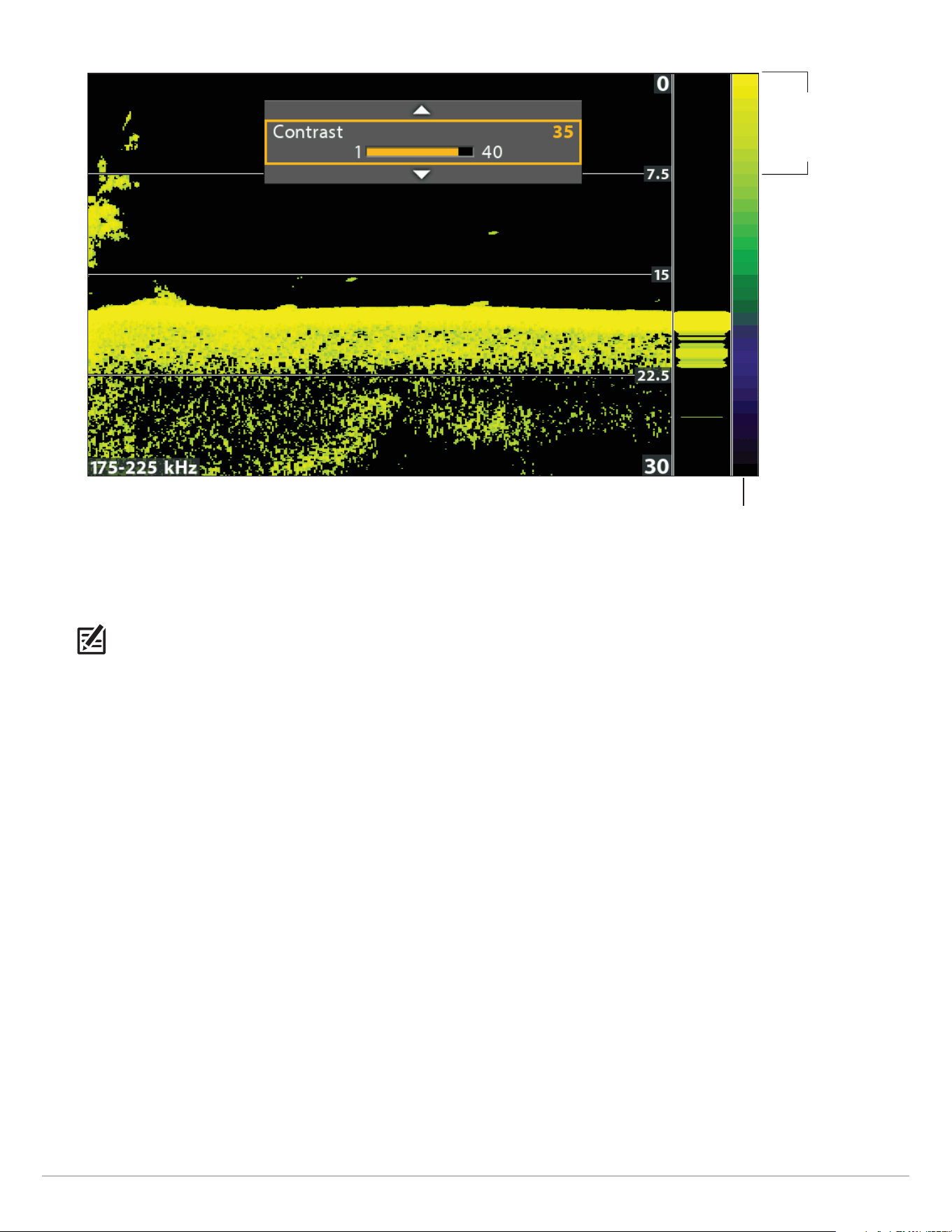
59
Sonar (2D)
color bar
Adjusting the Contrast
The high Contrast
setting uses the
top portion of
palette.
Select a Range of the Palette (Contrast)
Contrast allows you to choose a range of the Sonar Colors palette to display sonar returns. To see the current palette, display the
Color Bar on the Sonar View.
NOTE: To display or hide the Color Bar, see
Show/Hide Data on the Sonar View
.
When Contrast is set to 20 (default), the entire Sonar Colors palette (represented by the Color Bar) is used to display weak and
strong sonar returns. As you increase the Contrast, the top range of the Color Bar is used to display all sonar returns (whether weak
or strong). As you decrease the Contrast, the bottom range of the Color Bar is used to display all sonar returns (whether weak or
strong).
1. Sonar X-Press Menu: With a Sonar View displayed on-screen, press the MENU key once.
2. Select Contrast.
3. Press the RIGHT or LEFT Cursor keys to move the selection higher or lower on the color bar.
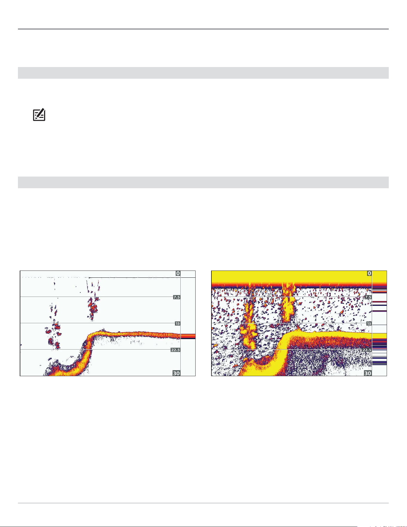
60
Sonar (2D)
Adjust Sonar Display Settings
Use the instructions in this section to adjust how the sonar returns are shown on the Sonar View, so you can tune into what you
want to see in the display. The settings in this section are optional. You can use the default display settings for the Sonar View, or
you can customize it with your preferences.
Filter Surface Clutter
Use Surface Clutter to reduce the noise that may appear at the top of the view caused by algae and aeration. The lower the setting,
the less surface clutter will be displayed. A higher setting allows more surface clutter to be displayed.
NOTE: You can also adjust the Noise Filter (see Set up Sonar: Adjust the Noise Filter).
1. Main Menu: Press the MENU key twice. Select the Sonar tab.
2. Select Surface Clutter.
3. Press the RIGHT or LEFT Cursor keys to adjust the setting.
Change the 2D SwitchFire Mode
SwitchFire controls how the sonar returns are displayed in the Sonar Views.
1. Main Menu: Press the MENU key twice. Select the Sonar tab.
2. Select 2D SwitchFire.
3. Select Clear Mode or Max Mode.
2D SwitchFire: Clear Mode 2D SwitchFire: Max Mode
Choose Clear Mode to see less clutter and more fish size accuracy on the
display. When Clear Mode is selected, the clutter is filtered, and sonar returns
are interpreted to provide more details about the objects within the transducer
beam, regardless of their location. In other words, a large arch on the display
means a large fish has been detected.
Choose Max Mode to see only raw sonar returns on the display. When Max Mode
is selected, you will see the maximum sonar information available within the
transducer beam, so more fish arches and better jig tracking are shown.
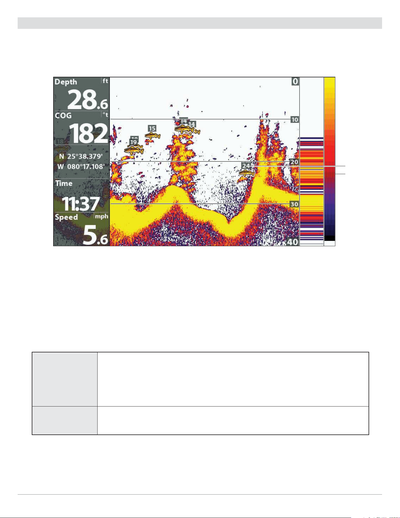
61
Sonar (2D)
Turn on/o Fish ID+ Settings
Fish ID+ uses advanced signal processing to interpret sonar returns and will display a fish symbol on the Sonar View when very
selective requirements are met. Also, if Fish ID+ is turned on, you can adjust the sensitivity used for detection and receive alerts
with the Fish ID Alarm turned on.
Fish ID+ Turned On
Fish ID+ symbol
(200 kHz beam)
depth
Turn on/off Fish ID+
When Fish ID+ is turned on, fish symbols will be shown on the Sonar View. The color of the fish symbols indicates the sonar beam
location, and the fish depth is shown above the symbol.
When Fish ID+ is turned off, the control head shows only the raw sonar returns on the display.
1. Main Menu: Press the MENU key twice. Select the Sonar tab.
2. Select Fish ID+.
3. Select On or Off.
On
Fish Symbols will display in the Sonar View when a fish is detected.
Orange Fish Symbols = targets detected in the 200 kHz narrow beam and Dual Spectrum.
Green Fish Symbols = targets detected in the 83 kHz wide beam or 455 kHz beam (DI, CHIRP
DI only).
Off
Raw sonar returns are shown on the Sonar View. If a fish is detected, the returns appear as
arches on the display to indicate potential targets.

62
Sonar (2D)
Adjust the Fish ID Sensitivity
Use Fish ID Sensitivity to adjust the threshold used for detecting a fish with Fish ID+. To display only larger species of fish as fish
symbols, select a low setting. To see smaller fish species or baitfish, select a high setting. Fish ID+ must be turned on to enable
this menu.
1. Turn on Fish ID+.
2. Main Menu: Press the MENU key twice. Select the Sonar tab.
3. Select Fish ID Sensitivity.
4. Press the RIGHT or LEFT Cursor keys to adjust the setting.
1 = low sensitivity (large fish only)
10 = high sensitivity (All: small fish up to large fish)
Turn on the Fish ID Alarm
To receive an on-screen alert when a fish is detected, turn on the Fish ID Alarm. Fish ID+ must be turned on to enable this alarm.
1. Turn on Fish ID+.
2. Main Menu: Press the MENU key twice. Select the Alarms tab.
3. Select Fish ID Alarm.
4. Select one of the following icons:
Off
All
Large/Medium
Large
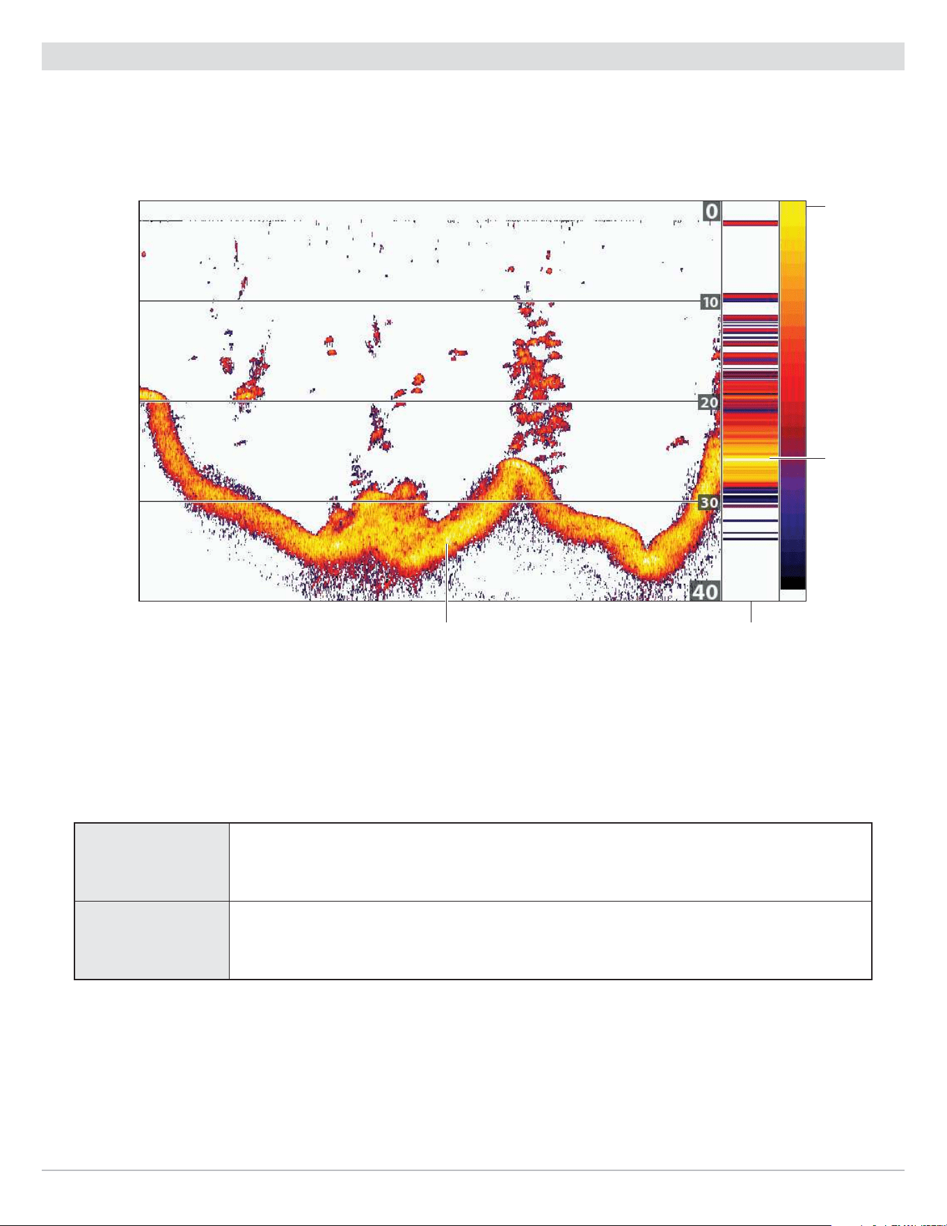
63
Sonar (2D)
Set the Bottom View Display
Bottom View selects the method used to represent bottom and structure on the display. Bottom View is also affected by the palette
selected in Sonar Colors (see Customize the Sonar View: Change the View Colors).
Bottom View set to WhiteLine
color bar with
sonar colors
set to palette 1
RTS Windowwhite shows strongest returns
white shows
strongest
returns
Change the Bottom View Setting
1. Main Menu: Press the MENU key twice. Select the Sonar tab.
2. Select Bottom View.
3. Select one of the following modes:
Structure ID
Structure ID will display the strongest return as specified by the palette selected in the Sonar
Colors menu.
WhiteLine
WhiteLine highlights the strongest sonar returns in white. This has the benefit of clearly
defining the bottom on the display.
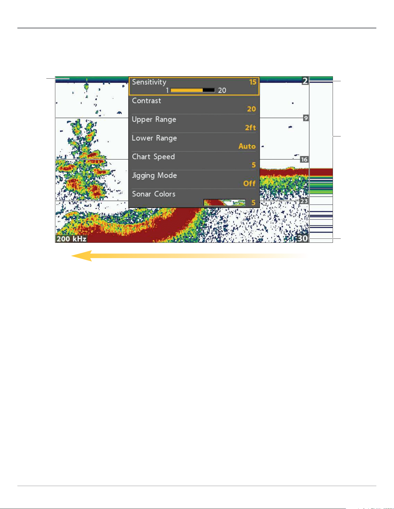
64
Sonar (2D)
Adjust Settings while you Fish
(Sonar X-Press Menu)
The X-Press Menu provides menu options to adjust the sensitivity and range as you fish. You can also control how fast the sonar
history scrolls across the screen. The menus allow you to see more or less of the sonar returns from the transducer beams as you
adjust each setting. Also, you can use key shortcuts on the view.
Adjusting Settings from the Sonar X-Press Menu (HELIX 7 CHIRP SI GPS G2)
upper range
chart speed
RTS Window
lower range
surface
clutter
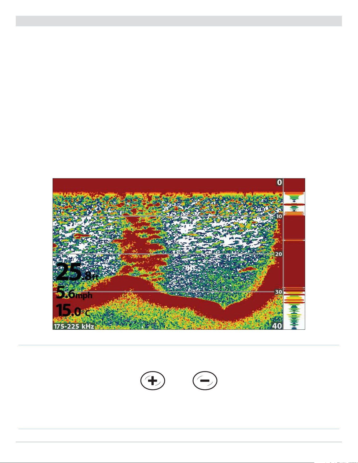
65
Sonar (2D)
Adjust the Sensitivity
Sensitivity controls how much detail is shown on the view. To eliminate the clutter from the display that is sometimes present in
murky or muddy water, decrease the sensitivity. When operating in very clear water or greater depths, increase the sensitivity to
see weaker returns.
Adjust the Sensitivity using the X-Press Menu
Use the following instructions to adjust the sensitivity.
1. Sonar X-Press Menu: With a Sonar View displayed on-screen, press the MENU key once.
2. Select Sensitivity.
3. Press the RIGHT or LEFT Cursor keys to increase or decrease the sensitivity.
Adjust the Sensitivity using the ZOOM Keys
If your control head includes +/-ZOOM keys, you can use them to adjust the sensitivity.
1. With a Sonar View displayed on-screen, press the +ZOOM key or −ZOOM key.
Adjusting the Sensitivity using the +/−ZOOM Keys
Decrease SensitivityIncrease Sensitivity
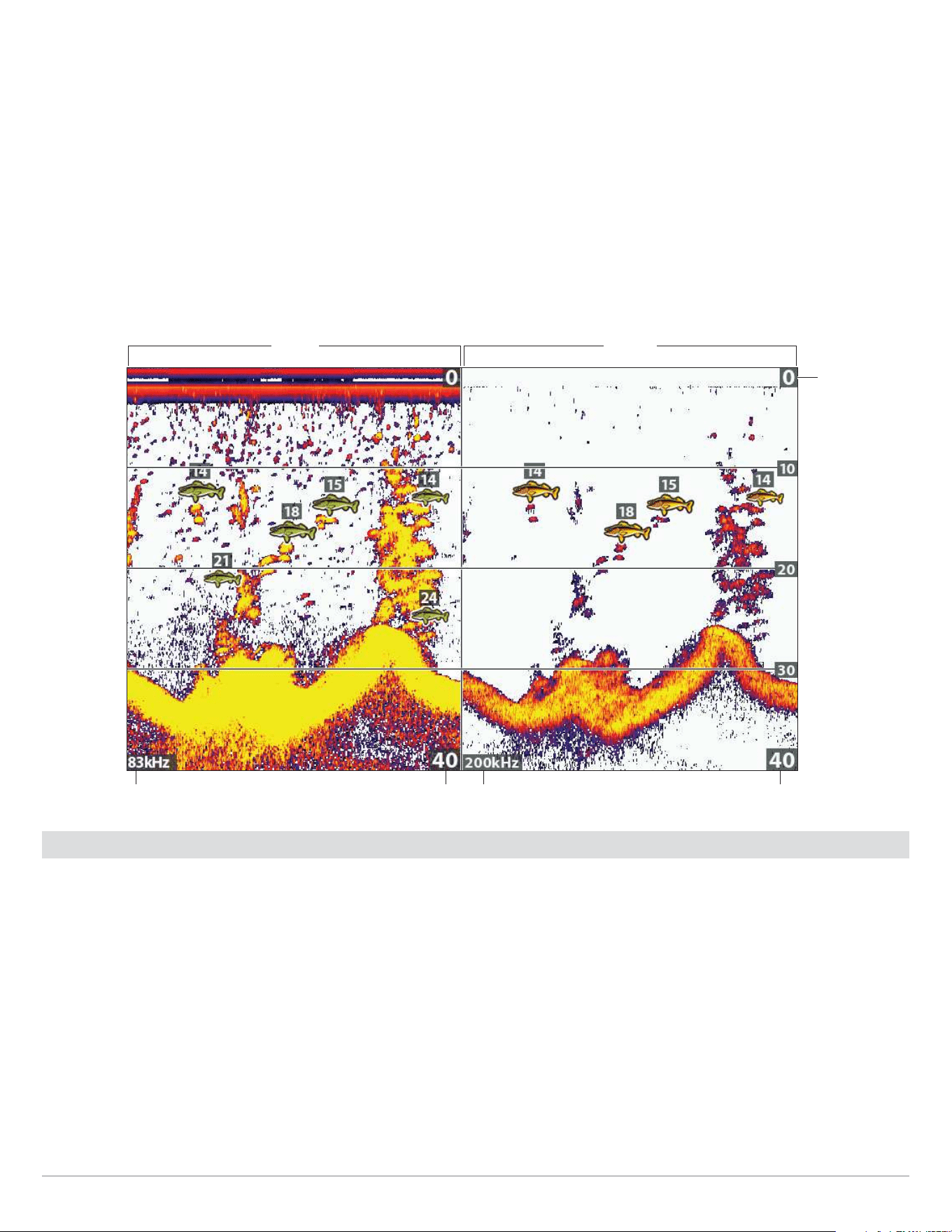
66
Sonar (2D)
Adjust Beam Sensitivity
Your control head model may allow you to adjust the sensitivity of individual frequencies. The available frequencies are determined
by your control head model and the installed transducer. Use the following instructions to adjust a single beam.
1. Main Menu (Custom User Mode): Press the MENU key twice. Select the Sonar tab.
2. Select 83 kHz Sensitivity or 455 kHz Sensitivity.
CHIRP Models: Select Medium Sensitivity Offset or High (455 kHz) Sensitivity Offset (DI, CHIRP DI models only).
3. Press the RIGHT or LEFT Cursor keys to increase or decrease the sensitivity.
For example, in the illustration shown below, the sensitivity of the 83 kHz beam in the Split Sonar View can be adjusted without
affecting the sensitivity of the 200 kHz sonar returns. For more information about this view, see Compare Sonar Beams.
Increasing the Sensitivity of the 83 kHz Beam (83 kHz/200 kHz)
lower range
83 kHz
lower rangefrequency frequency
200 kHz
upper range
Select a Range of the Palette
(Contrast)
Contrast allows you to choose a range of the Sonar Colors palette to display sonar returns. To see the current palette, display
the Color Bar on the Sonar View. For details, see Customize the Sonar View: Change the View Colors and Show/Hide Data on the
Sonar View.
When Contrast is set to 20 (default), the entire Sonar Colors palette (represented by the Color Bar) is used to display weak and
strong sonar returns. As you increase the Contrast, the top range of the Color Bar is used to display all sonar returns (whether weak
or strong). As you decrease the Contrast, the bottom range of the Color Bar is used to display all sonar returns (whether weak or
strong).
1. Sonar X-Press Menu: With a Sonar View displayed on-screen, press the MENU key once.
2. Select Contrast.
3. Press the RIGHT or LEFT Cursor keys to move the selection higher or lower on the color bar.
67
Sonar (2D)
Set the Upper/Lower Range
Upper Range and Lower Range control how much of the water column is displayed on the view. For example, if you are only
interested in the area between 20 and 50 feet deep, set the Upper Range to 20 and the Lower Range to 50. The view will not display
sonar returns outside of the set ranges, and greater detail for the selected range will be displayed.
1. Sonar X-Press Menu (Custom User Mode): With a Sonar View displayed on-screen, press the MENU key once.
2. Select Upper Range. Press the RIGHT or LEFT Cursor keys to adjust the setting.
3. Select Lower Range. Select Auto or set a specific depth (manual).
Auto: The Lower Range will be adjusted by the control head to follow the bottom automatically.
Manual: The control head locks onto the depth you select.
NOTE: There must be a difference of 10 feet between the upper and lower range settings.
Change the Chart Speed
Chart Speed controls how fast the sonar history moves across the view and how much detail is shown. A faster speed is preferred
by most anglers, and the sonar history moves quickly across the view. To slow down the sonar history display, select a lower setting.
Regardless of the Chart Speed setting, the RTS Window will update at the maximum rate possible for depth conditions.
1. Sonar X-Press Menu: With a Sonar View displayed on-screen, press the MENU key once.
2. Select Chart Speed.
3. Press the RIGHT or LEFT Cursor keys to adjust the setting.
Turn on/o Jigging Mode (CHIRP SI, CHIRP MEGA SI, CHIRP MEGA SI+ models only)
If you have a CHIRP SI, CHIRP MEGA SI or CHIRP MEGA SI+ model and a Dual Beam SI transducer, you can use Jigging Mode to refine
the sonar returns shown in the Sonar View.
NOTE: This feature is only available when a Dual Beam SI transducer is connected. Jigging Mode is not needed with High Wide
Dual Spectrum CHIRP transducers.
1. Sonar X-Press Menu: With a Sonar View displayed on-screen, press the MENU key once.
2. Select Jigging Mode.
3. Select On or Off.
On
Turn on Jigging Mode if you’ve selected Medium or Medium/High Frequency in the 2D CHIRP
Display Frequency menu (with 2D CHIRP Mode turned on), or if you’ve selected 83 kHz or 83/200
kHz in the 2D Display Frequency menu (with 2D CHIRP Mode turned off). When Jigging Mode is
turned on, the sonar returns are refined on the view, and the chart speed slows down to show
more detail.
Off
Turn off Jigging Mode if you’ve selected Low Frequency in the 2D CHIRP Display Frequency
menu (with 2D CHIRP Mode turned on), or if you’ve selected 200 kHz in the 2D Display
Frequency menu (with 2D CHIRP Mode turned off). Turn off Jigging Mode to display the sonar
history at the selected chart speed and see coarser returns on the display.
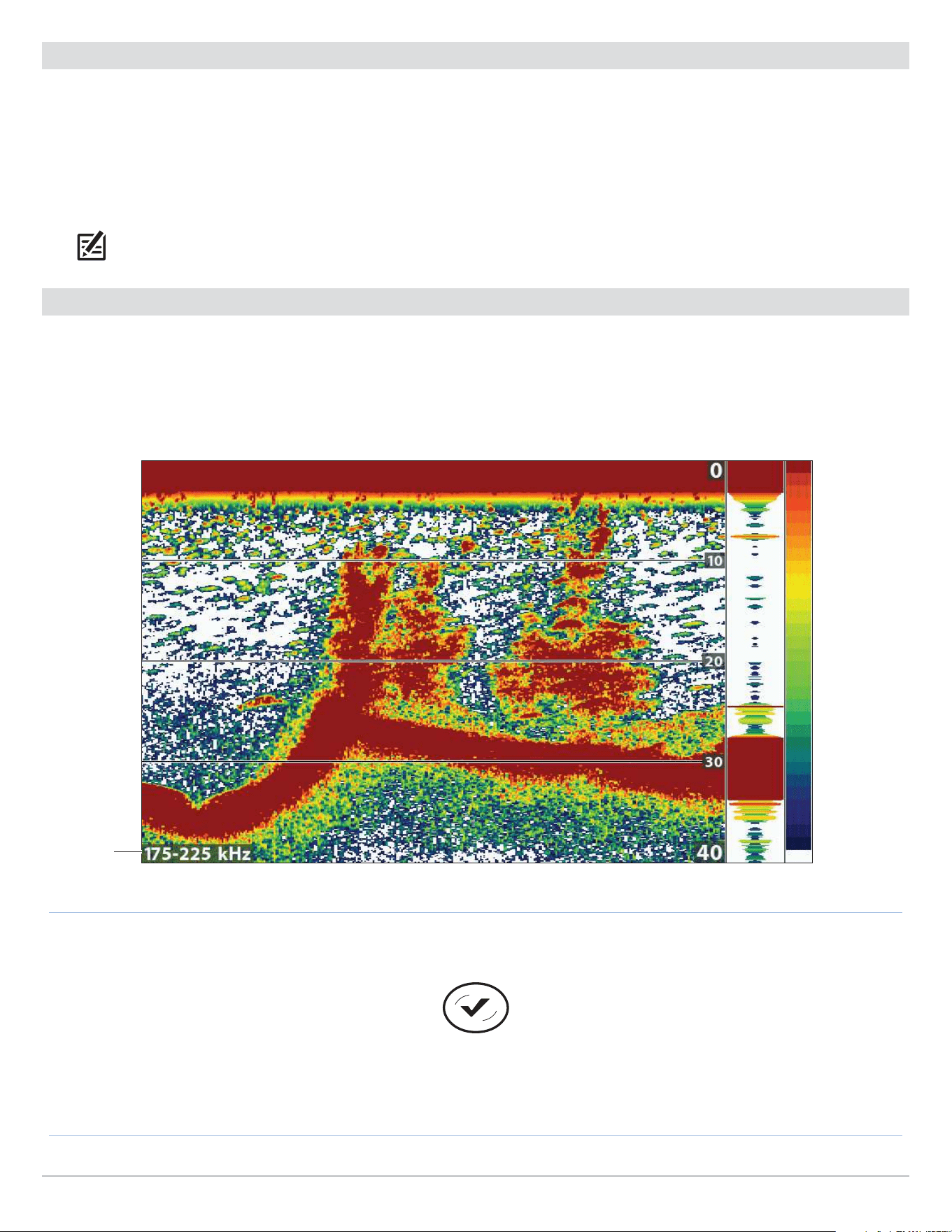
68
Sonar (2D)
Change the Sonar Colors Palette
The Sonar X-Press Menu allows you to quickly change the display palette while you fish. See Customize the Sonar View: Change
the View Colors for more information.
1. Sonar X-Press Menu: With a Sonar View displayed on-screen, press the MENU key once.
2. Select Sonar Colors.
3. Select a palette.
NOTE: To display or hide the Color Bar, see Customize the Sonar View.
Switch Frequencies
If the transducer includes more than one downbeam frequency, use the CHECK/INFO key to quickly change the frequency used in
the 2D Sonar View. For more information see Sonar Overview and Set up Sonar.
1. With a Sonar View displayed on-screen, press the CHECK/INFO key.
Using the CHECK key to Switch Frequencies
frequency
label
Switch Frequencies
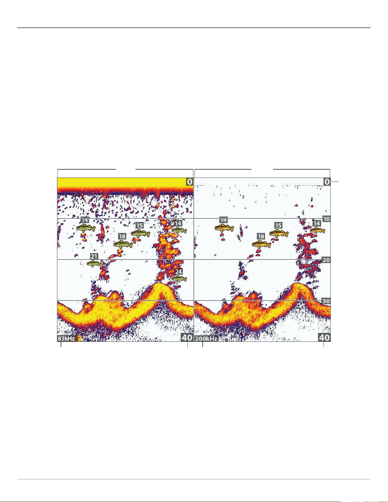
69
Sonar (2D)
Compare Sonar Beams
(Split Sonar View)
Split Sonar View displays sonar returns from each down beam frequency on separate sides of the view. You can use this view to
make side by side comparisons between the sonar returns from both beams. The beams are determined by your Humminbird model
and the installed transducer.
Frequencies: Use this view to compare the 83 kHz and 200 kHz beams. If you have a DI or CHIRP DI model, 455 kHz and 200
kHz will be displayed side by side in this view. When 2D CHIRP Mode is turned on, you can also compare beams.
Fish ID+: It is also helpful to turn on Fish ID+ in Split Sonar View so you can see where the fish are located within each
transducer beam (see Adjust Sonar Display Settings:
Turn on/off Fish ID+ Settings
).
Display the Split Sonar View
1. Press and hold the VIEW key.
2. Select Sonar > Split Sonar View.
Reviewing Beams Separately in Split Sonar View (83 kHz/200 kHz)
lower range
83 kHz
lower rangefrequency frequency
200 kHz
upper range
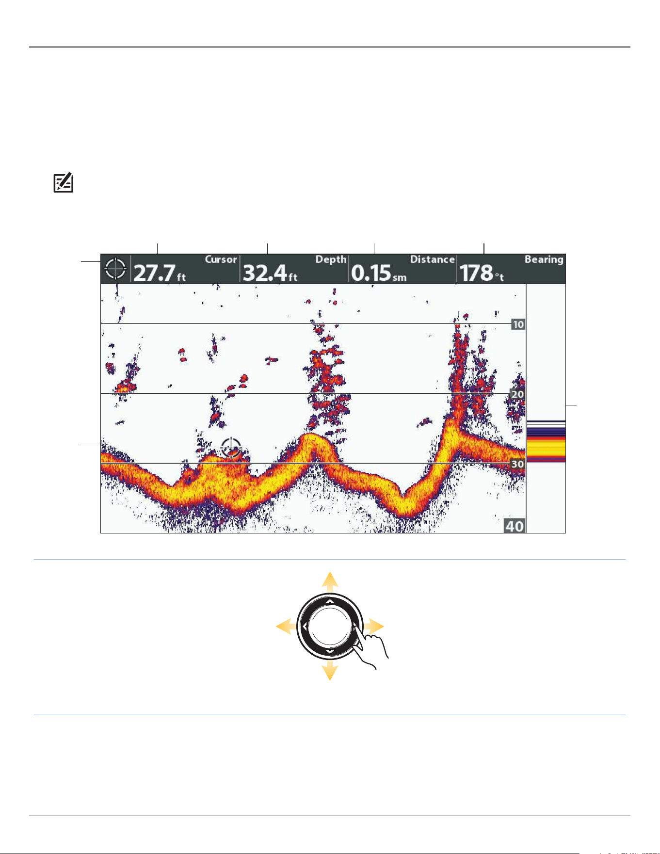
70
Sonar (2D)
Review Sonar History
Press any arrow on the Cursor Control key, and the sonar history will freeze and the cursor will display on-screen. If you move the
cursor over a sonar return, digital readouts for the cursor position are displayed on the view. The RTS Window continues to update
at the fastest rate possible for depth conditions (see Customize the Sonar View).
Freeze the Sonar History
1. Press any arrow on the Cursor Control key.
2. Move the cursor over a sonar return.
NOTE: To mark a waypoint or start navigation to the cursor position, see Navigation in Sonar Views.
Move the Cursor
Reviewing the Depth of the Cursor Position
cursor
digital
readouts
RTS Window
cursor
cursor depth depth below cursor distance to cursor position bearing to cursor position

71
Sonar (2D)
Zoom In/Zoom Out
Use the Sonar Zoom View to see a magnified view of the bottom and structure. For example, if there are fish close to the bottom or
near structure (tree, vegetation, etc.), Sonar Zoom View makes it easier to see the separate sonar returns that might be displayed
close together.
Display the Sonar Zoom View
1. Press and hold the VIEW key.
2. Select Sonar > Sonar Zoom View.
Zoom In/Zoom Out using the ZOOM Keys
If your control head includes +/− ZOOM keys, use the instructions in this section to use the ZOOM feature.
Magnify Bottom Structure (Zoom In/Out)
1. Display the Sonar Zoom View on-screen.
2. Zoom In: Press the +ZOOM key.
Zoom Out: Press the –Zoom key.
Magnify the Cursor Position (Zoom In/Out)
1. Display the Sonar Zoom View on-screen.
2. Use the Cursor Control key to move the cursor to a position on the view.
3. Zoom In: Press the +ZOOM key.
Zoom Out: Press the -Zoom key.
4. Close: Press the EXIT key.
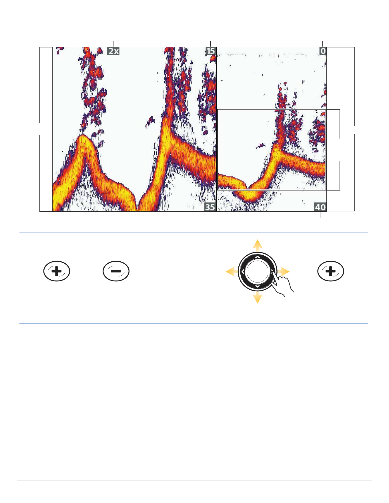
72
Sonar (2D)
ZOOM Out ZOOM InZOOM In
OR
Move the Cursor
zoom
preview
range
full range
zoomed
view
Magnifying Sonar Returns in Sonar Zoom View (Bottom Lock Off)
zoom level upper range, zoom view upper range, full range view
lower range, zoom view lower range, full range view

73
Sonar (2D)
Zoom In/Zoom Out using the X-Press Menu
If your control head does not include ZOOM keys, you will use the Zoom Level menu to use the ZOOM feature.
Magnify Bottom Structure (Zoom In/Out)
1. Display the Sonar Zoom View on-screen.
2. Press the MENU key once.
3. Select Zoom Level.
4. Press the RIGHT or LEFT Cursor keys to adjust the setting.
Magnify the Cursor Position (Zoom In/Out)
1. Display the Sonar Zoom View on-screen.
2. Use the Cursor Control key to move the cursor to a position on the view.
3. Press the MENU key once.
4. Select Zoom Level.
5. Press the RIGHT or LEFT Cursor keys to adjust the setting.
6. Close: Press the EXIT key.
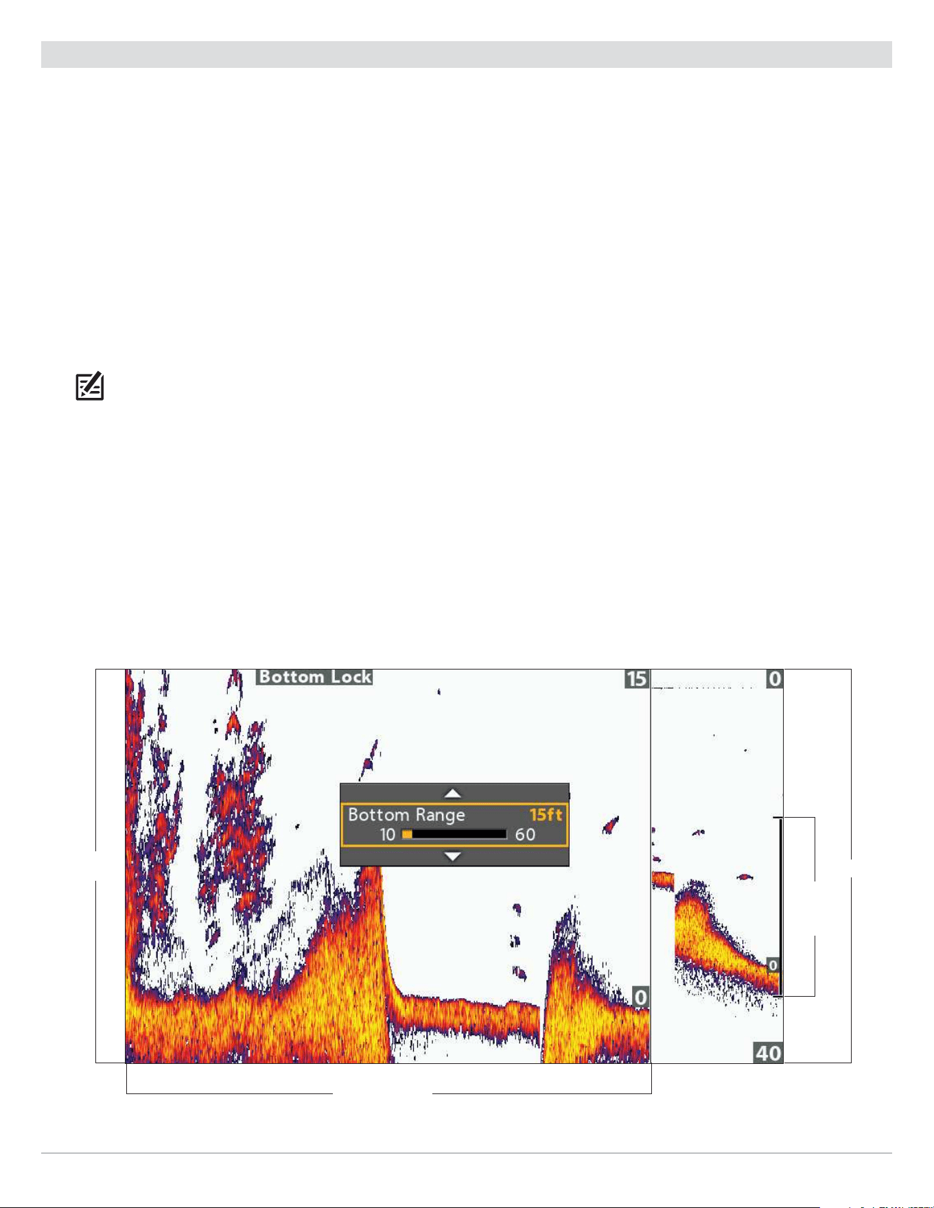
74
Sonar (2D)
Adjust Sonar Zoom View Display Settings
Turn on/off Bottom Lock
Use Bottom Lock and Bottom Range to focus on the bottom and control how much of the water column is shown in Sonar Zoom
View. Bottom Lock continuously graphs the bottom at a constant point on the display regardless of changes in depth. This “flattens”
out the bottom contour but is effective at showing fish on or near the bottom.
1. Sonar X-Press Menu: With a Sonar Zoom View displayed on-screen, press the MENU key once.
2. Select Bottom Lock. Press the RIGHT Cursor key to select On.
3. Press the UP Cursor key. Select Bottom Range.
4. Press the RIGHT or LEFT Cursor keys to adjust the range. The range is measured up from the bottom.
Low Setting: useful for seeing low-lying bottom structure or details of the bottom return.
High Setting: useful for seeing large structure in deeper water.
NOTE: If you see a wavy band on the view that mirrors the change in depth, the Bottom Range might be set deeper than the actual
water depth. In this case, decrease the Bottom Range setting.
Change the Width of the Zoomed View
Use the instructions in this section to change the width of the zoomed view in Sonar Zoom View.
1. Main Menu: Press the MENU key twice. Select the Sonar tab.
2. Select Zoom Width.
3. Press the RIGHT or LEFT Cursor keys to adjust the setting.
Setting the Bottom Range and Zoom Width (Bottom Lock On)
zoom width (wide)
zoomed
view
zoom
preview,
bottom
range
full range
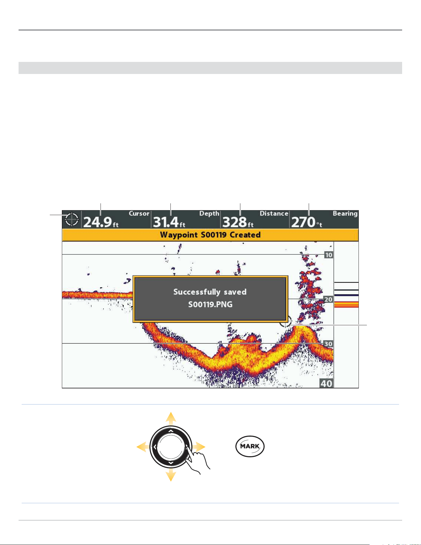
75
Sonar (2D)
Navigation in Sonar Views
To mark waypoints and start navigation, the control head must have a GPS Fix from a connected or internal GPS receiver. See
Getting Started for more information.
Mark a Waypoint
You can mark a waypoint at the boat position or the cursor position. Waypoints are saved to the Waypoint Management dialog box
(see Manage your Navigation Data).
Mark a Waypoint at the Boat Position
1. Press the MARK key.
Mark a Waypoint at the Cursor Position
1. Use the Cursor Control key to move the cursor to a position on the view.
2. Press the MARK key twice.
Press Twice to
Mark a Waypoint
Move the Cursor
cursor
digital
readouts
cursor
cursor depth
Marking a Waypoint at the Cursor Position
depth below cursor
distance to cursor position bearing to cursor position

76
Sonar (2D)
Navigate to a Position
Use the instructions in this section to start navigation to a position in the view. See Navigation Overview for more information
about these features.
Navigate to the Cursor Position
1. Use the Cursor Control key to move the cursor to a position on the view.
2. Press the GOTO key twice.
When you press the GOTO key, a waypoint will be marked at the cursor position.
Navigate to a Saved Position
If you press the GOTO key, you can choose to start navigation from a list of saved waypoints and routes.
1. Press the GOTO key.
2. Select Nav Data. Press the RIGHT Cursor key.
3. Use the Cursor Control key to select a saved waypoint or route.
4. Press the RIGHT Cursor key to start navigation.
Cancel Navigation
1. Press the MENU key once.
2. Select Cancel Navigation. Press the RIGHT Cursor key.
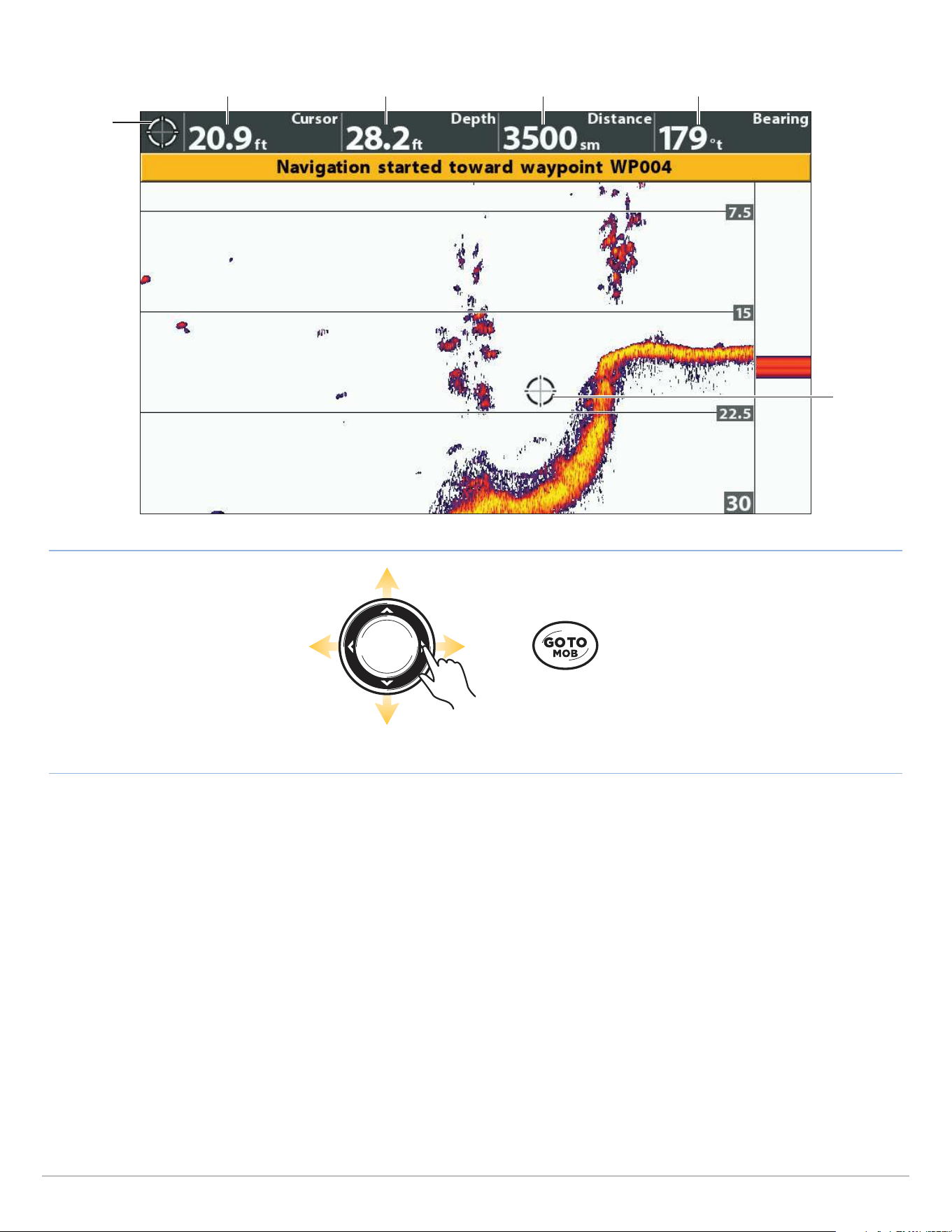
77
Sonar (2D)
Press Twice to
Start Navigation
Move the Cursor
cursor
digital
readouts
cursor depth
Starting Navigation to the Cursor Position
cursor
depth below cursor
distance to cursor position bearing to cursor position
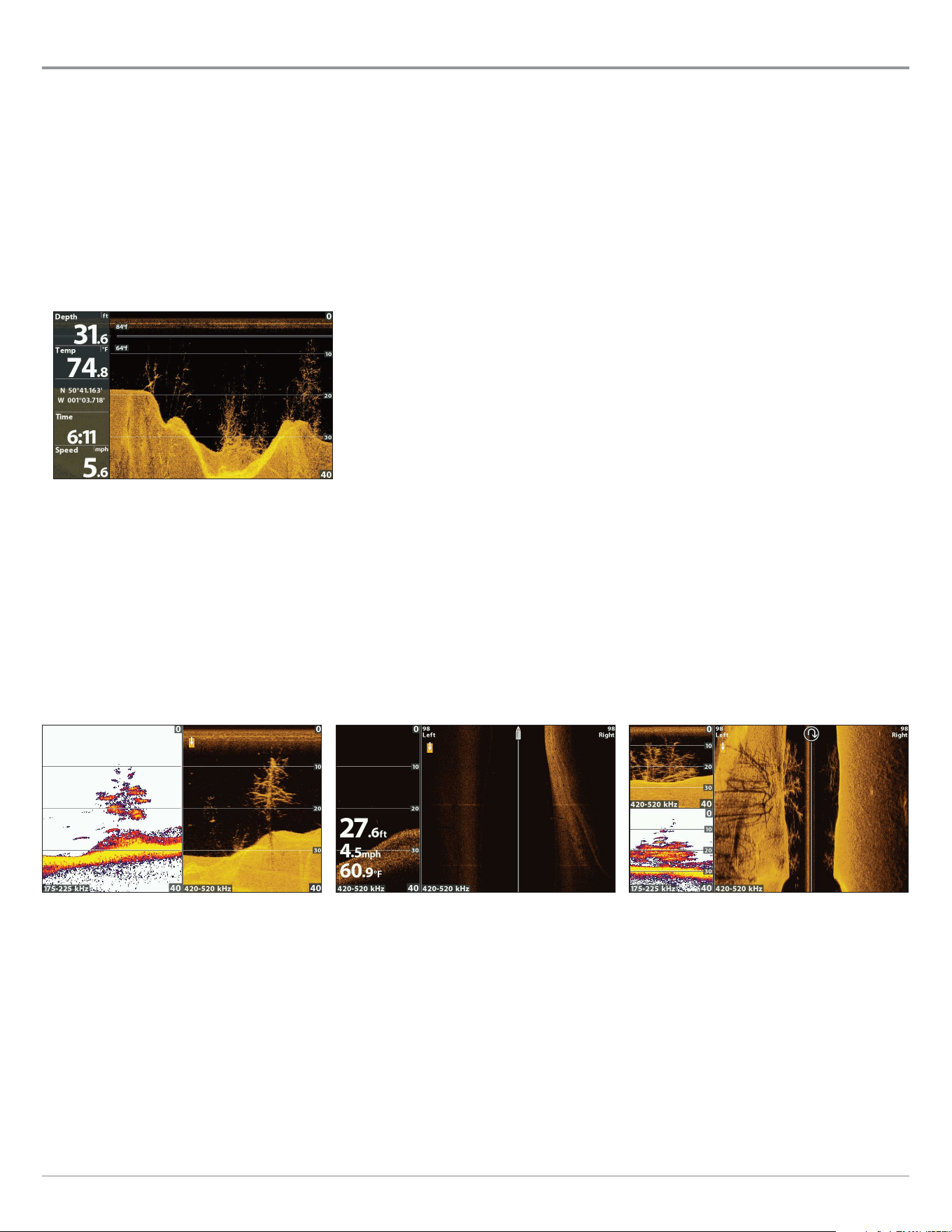
78
Down Imaging Sonar
Display a Down Imaging View On-Screen
(Down Imaging and Side Imaging models only)
There are a variety of views available to display Down Imaging data. You can also customize the view by showing or hiding information
(see Customize the Down Imaging View), and you can adjust the sonar settings to refine the information displayed on-screen (see
Adjust Settings While you Fish). The changes you make are applied to all Down Imaging views.
Display a Down Imaging View
1. Press and hold the VIEW key.
2. Select Sonar > Down Imaging View.
Down Imaging View
Display a Down Imaging Combo View
1. Press and hold the VIEW key.
2. To open a Down Imaging Combo View, select Sonar.
To open a Chart Combo View (Down Imaging and Chart together), select Chart.
3. Select a view to display on-screen. Press the RIGHT Cursor key.
Sonar > Down/Side/Sonar Combo View
For more information, see
the Sonar and Side Imaging sections.
Sonar > Down/Side Combo View
For more information, see
the Side Imaging section.
Sonar > Down/Sonar Combo View
For more information, see
the Sonar section.
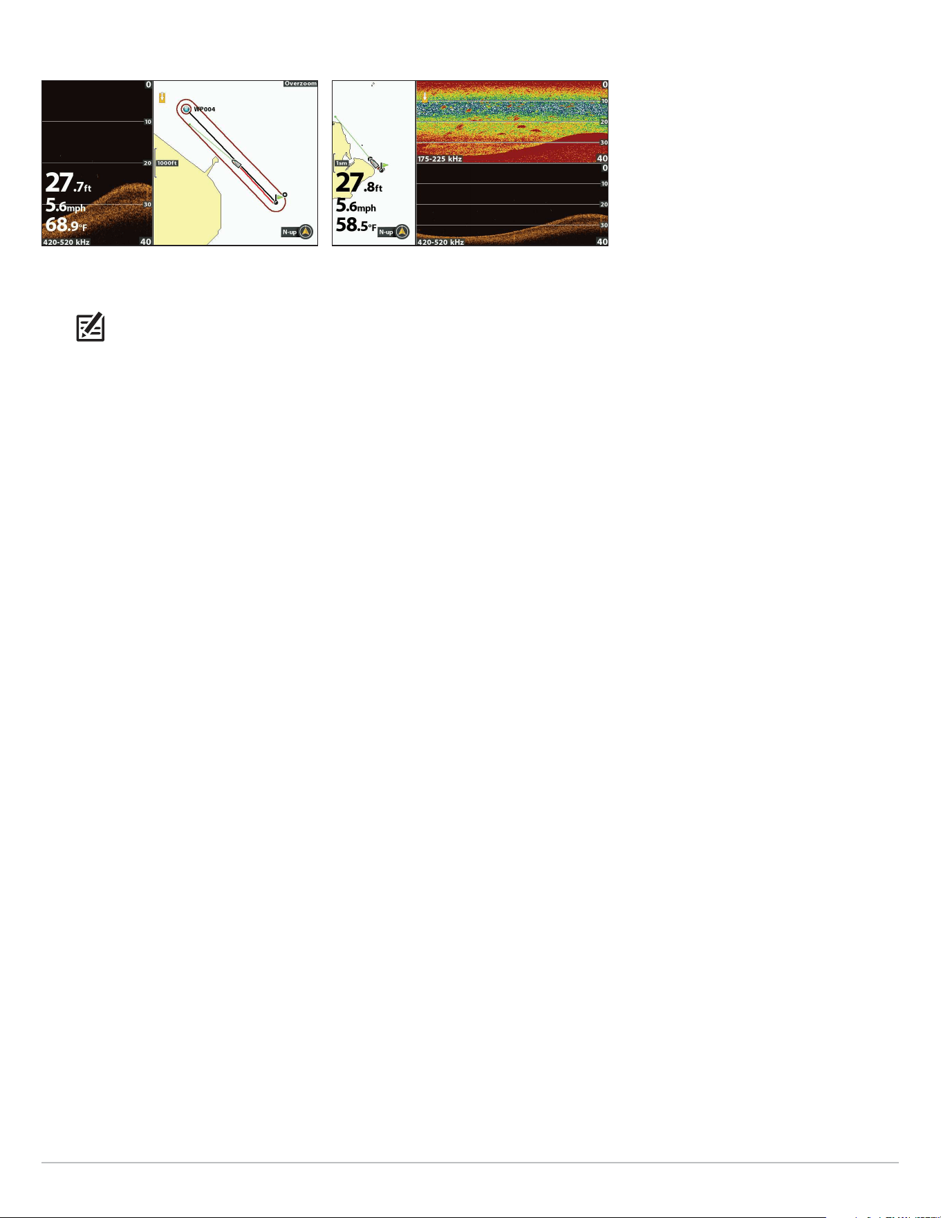
79
Down Imaging Sonar
For more information, see
the Sonar and Navigation sections.
Chart > Chart/Sonar/Down Combo View
(Map Source: Contour XD)
For more information, see
Navigation Overview.
Chart > Chart/Down Combo View
(Map Source: Contour XD)
NOTE: The available views are determined by your control head model and the installed transducer. For a complete list of the
views available on your control head, press the MENU key twice, and select the Views tab. See each related section of the manual
(Views, Sonar, Side Imaging, Navigation Overview, etc.) for more information.
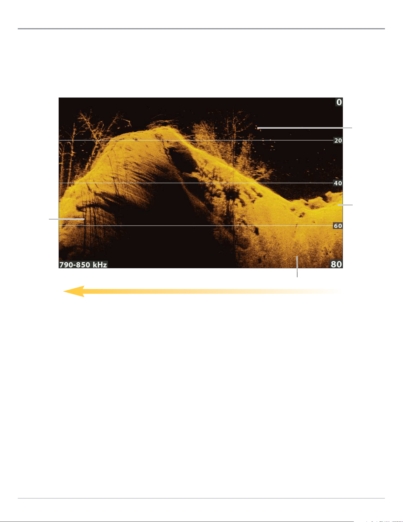
80
Down Imaging Sonar
Understand the Down Imaging View
The images you see on the Down Imaging display are produced using sonar technology. Each time the unit pings, a strip of data
representing all the echoes received by the transducer are put together on the display to form the image that you see. Like
traditional 2D Sonar, the sonar history scrolls left across the screen.
Down Imaging beams “illuminate” the bottom contour, structure, and fish. The beams are wide (side to side) but very thin from
front to back.
Sonar History — Historical returns scroll left across the view.
Down Imaging View (HELIX 9 CHIRP DI GPS G2N)
dark shades
shadow
light shades
white
streaks/clouds
Use the light and dark parts of the display to interpret the objects under your boat as follows:
Dark shades represent soft returns (mud, sand) or descending terrain.
Light shades represent denser terrain (timber, rocks) or rising terrain. A very hard bottom may appear as white on the display.
White Streaks or Clouds may represent fish on the display.
Shadows are not caused by light but by the lack of a sonar return. Objects standing on the bottom cause a sonar shadow to
appear on the display. The longer the shadow, the taller the object. Fish may also cast shadows. You can use the shadow to
interpret where the fish or object is located in relation to the bottom.
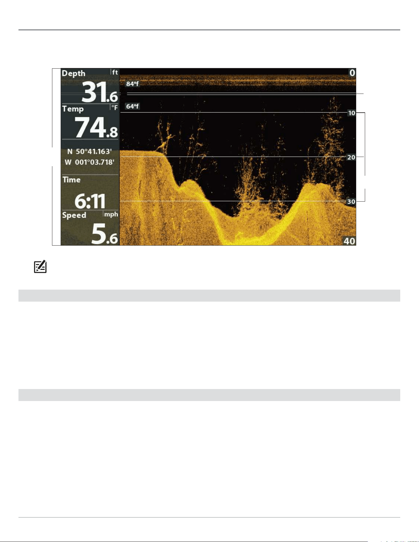
81
Down Imaging Sonar
Customize the Down Imaging View
You can customize the Down Imaging views by showing or hiding information, such as depth lines, temperature graph, and digital
readouts. You can also change the color palette.
temperature
graph
Customizing the Down Imaging View
digital
readouts set
to boxes
depth
lines
NOTE: Digital readouts can be displayed as an overlay, or they can be displayed in data boxes (see Views: Display Digital
Readouts).
Show/Hide Depth Lines
The depth lines show incremental marks between the upper and lower depth range. See Adjust Settings While you Fish for details.
The Depth Lines menu is shared with the Sonar View, so turning them on or off will affect the Sonar Views and the Down Imaging
Views.
1. Main Menu (Custom User Mode): Press the MENU key twice. Select the Sonar tab.
2. Select Depth Lines.
3. Select On (show) or Off (hide).
Show/Hide the Temperature Graph
The temperature graph displays the temperature changes over the recent sonar history. A temperature input from the installed
transducer or temp/speed accessory is required to enable this feature. The Temperature Graph menu is shared with the Sonar
View, so turning it on or off will affect the Sonar Views and the Down Imaging Views.
1. Main Menu: Press the MENU key twice. Select the Sonar tab.
2. Select Temperature Graph.
3. Select On (show) or Off (hide).
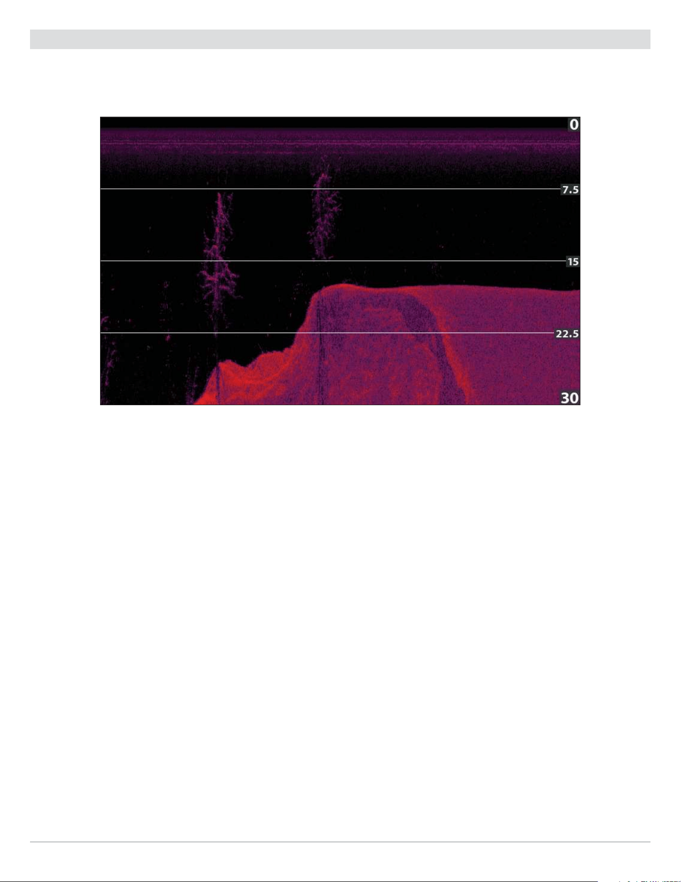
82
Down Imaging Sonar
Change the View Colors
The DI Colors menu changes the palette used to display sonar returns on the view.
Down Imaging View with Palette 10 Selected (DI Colors)
Change the Down Imaging Colors Palette
1. Down Imaging X-Press Menu: With a Down Imaging View displayed on-screen, press the MENU key once.
2. Select DI Colors.
3. Select a palette.
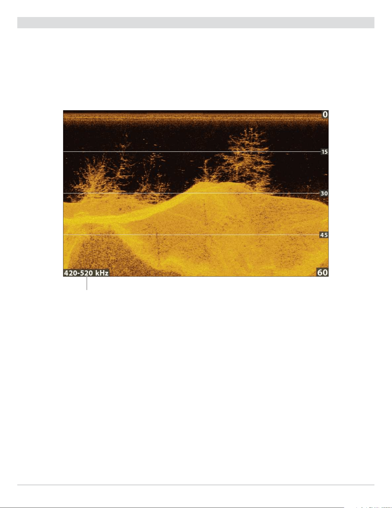
83
Down Imaging Sonar
Show/Hide the Frequency Label
The Frequency Label displays the currently selected frequencies. See Set up Sonar.
1. Main Menu: Press the MENU key twice. Select the Sonar tab.
2. Select Frequency Label.
3. Select On (show) or Off (hide).
Down Imaging View with the Frequency Label Turned On
selected display
frequency
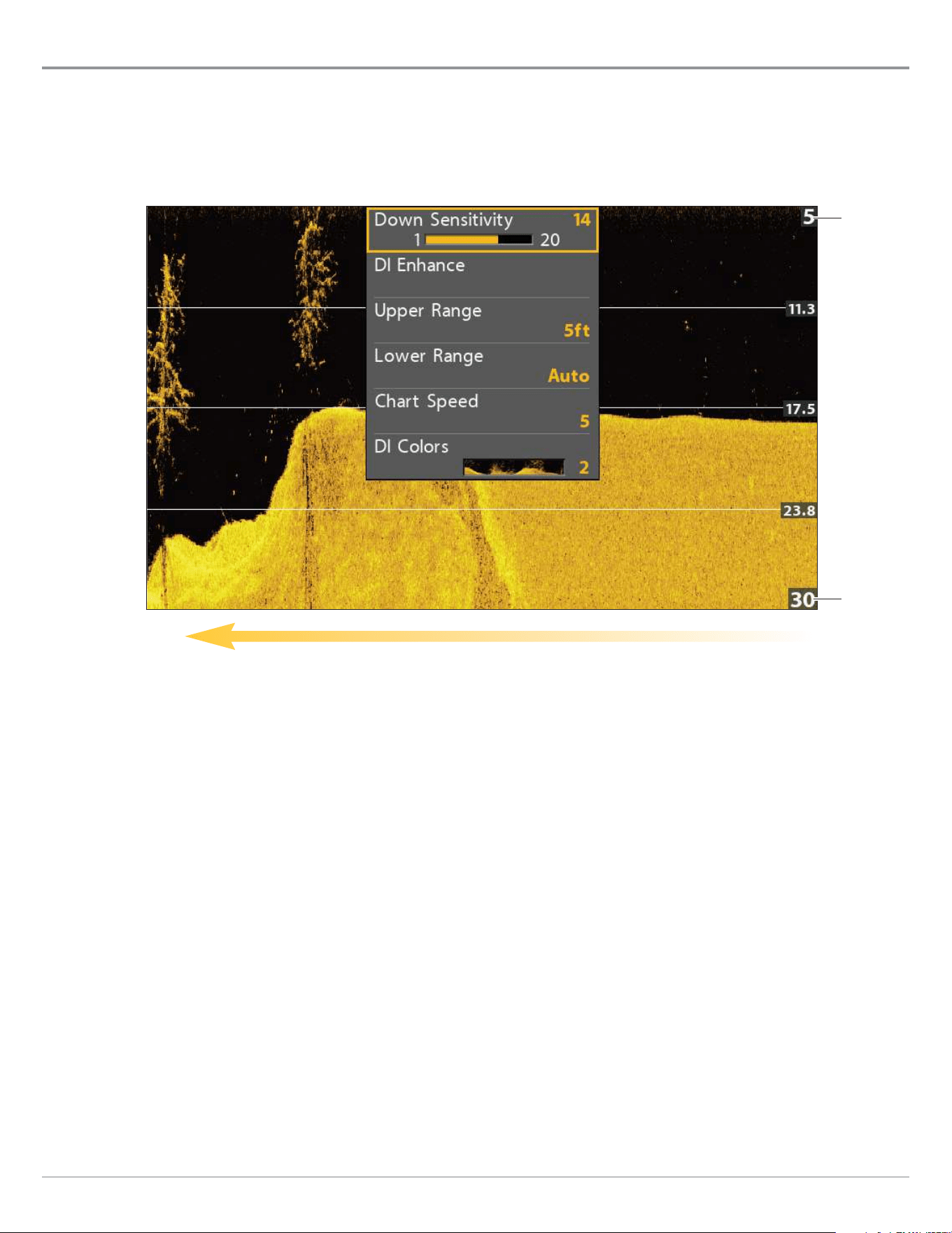
84
Down Imaging Sonar
Adjust Settings while you Fish
(Down Imaging X-Press Menu)
The X-Press Menu provides menu options to adjust the sensitivity and range as you fish. You can also control how fast the sonar
history scrolls across the screen. The menus allow you to see more or less of the sonar returns from the transducer beams as you
adjust each setting. Also, you can use key shortcuts on the view.
Adjusting Settings from the Down Imaging X-Press Menu
chart speed
lower range
upper range
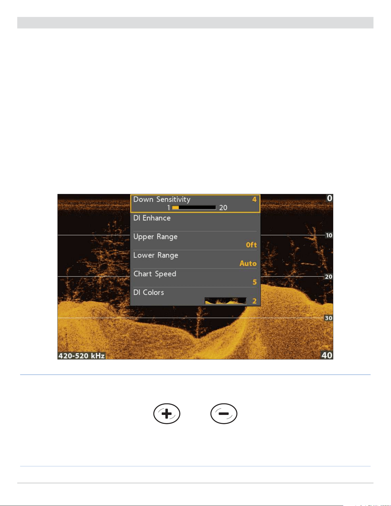
85
Down Imaging Sonar
Adjust Sensitivity
Sensitivity controls how much detail is shown on the view. You can adjust sensitivity from the X-Press Menu or the DI Enhance menu
(see Enhance the Down Imaging View). The sensitivity can also be adjusted using the +/− ZOOM keys.
Decrease the sensitivity to eliminate the clutter from the display that is sometimes present in murky or muddy water. When
operating in very clear water or greater depths, increase the sensitivity to see weaker returns.
Adjust the Sensitivity using the X-Press Menu
1. Down Imaging X-Press Menu: With a Down Imaging View displayed on-screen, press the MENU key once.
2. Select Down Sensitivity.
3. Press the RIGHT or LEFT Cursor keys to increase or decrease the sensitivity.
Adjust the Sensitivity using the ZOOM Keys
If your control head includes +/-ZOOM keys, you can use them to adjust the sensitivity.
1. With a Sonar View displayed on-screen, press the +ZOOM key or −ZOOM key.
Decrease SensitivityIncrease Sensitivity
Adjusting the Sensitivity using the +/−ZOOM Keys
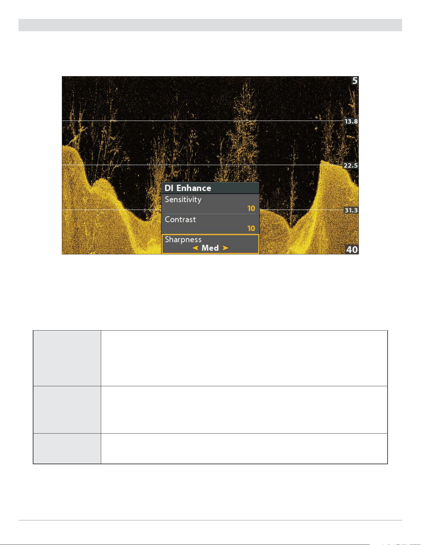
86
Down Imaging Sonar
Enhance the Down Imaging View
The DI Enhance menu allows you to adjust the sensitivity, contrast, and sharpness on the Down Imaging View. As you adjust each
setting, the changes are displayed immediately on the view.
Enhancing the Down Imaging View
Enhance the Down Imaging View
1. Down Imaging X-Press Menu: With a Down Imaging View displayed on-screen, press the MENU key once.
2. Select DI Enhance. Press the RIGHT Cursor key.
3. Use the Cursor Control key to select each menu and adjust the setting.
Sensitivity
Sensitivity controls how much detail is shown on the view. Decrease the sensitivity to
eliminate the clutter from the display that is sometimes present in murky or muddy water.
When operating in very clear water or greater depths, increase the sensitivity to see weaker
returns that may be of interest. This menu can also be adjusted from the Down Imaging
X-Press Menu (DI Sensitivity).
Contrast
Adjust the Contrast setting to accent the light and dark parts of the Down Imaging data to
provide greater definition. To intensify the strong returns, increase the contrast. To intensify
the weak returns, decrease the contrast.
Sharpness Turn on sharpness and select a filter level to sharpen the edges of the Down Imaging data.

87
Down Imaging Sonar
Set the Upper/Lower Range
Upper Range and Lower Range control how much of the water column is displayed on the view. For example, if you are only
interested in the area between 20 and 50 feet deep, set the Upper Range to 20 and the Lower Range to 50. The view will not display
sonar returns outside of the set ranges, and greater detail for the selected range will be displayed.
1. Down Imaging X-Press Menu (Custom User Mode): With a Down Imaging View displayed on-screen, press the MENU key once.
2. Select Upper Range. Press the RIGHT or LEFT Cursor keys to adjust the setting.
3. Select Lower Range. Select Auto or set a specific depth (manual).
Auto: The Lower Range will be adjusted by the control head to follow the bottom automatically.
Manual : The control head locks onto the depth you select.
NOTE: There must be a difference of 10 feet between the upper and lower range settings.
Change the Chart Speed
Chart Speed controls how fast the sonar history moves across the view and how much detail is shown.
1. Down Imaging X-Press Menu: With a Down Imaging View displayed on-screen, press the MENU key once.
2. Select Chart Speed.
3. Press the RIGHT or LEFT Cursor keys to adjust the setting.
Change the DI Colors
The Down Imaging X-Press Menu allows you to quickly change the display palette while you fish. See Customize the Down Imaging
View: Change the View Colors for more information.
1. Down Imaging X-Press Menu: With a Down Imaging View displayed on-screen, press the MENU key once.
2. Select DI Colors.
3. Select a palette.

88
Down Imaging Sonar
Switch Frequencies
If the transducer includes more than one frequency for Down Imaging, use the CHECK/INFO key to quickly change the frequency
used in the Down Imaging View. For more information see Sonar Overview and Set up Sonar.
1. With a Down Imaging View displayed on-screen, press the CHECK/INFO key.
Switch Frequencies
Using the CHECK key to Switch Frequencies (HELIX 9 CHIRP DI GPS G2N)
frequency
label

89
Down Imaging Sonar
Review Down Imaging History and Zoom In/Out
In addition to adjusting the sonar settings while you fish, you can freeze the sonar history, magnify sonar returns, and review
position information.
Freeze the Down Imaging View
Press any arrow on the Cursor Control key, and the sonar history will freeze and the cursor will display on-screen. If you move the
cursor over a sonar return, digital readouts for the cursor position are displayed on the view.
1. Press any arrow on the Cursor Control key.
2. Move the cursor over a sonar return.
3. Review the cursor position and depth information in the digital readouts.
NOTE: To mark a waypoint or start navigation to the cursor position, see Navigation in Down Imaging Views.
Zoom In/Zoom Out using the X-Press Menu
If your control head does not include ZOOM keys, you will use the X-Press menu to magnify a selected part of the view.
1. Use the Cursor Control key to move the cursor to a position on the view.
2. Press the MENU key once.
3. Select DI Zoom.
4. Press the RIGHT or LEFT Cursor keys to adjust the setting.
5. Close: Turn off DI Zoom.
Zoom In/Zoom Out using the ZOOM Keys
If your control head includes +/−ZOOM keys, use the instructions in this section to magnify the selected part of the view.
1. Use the Cursor Control key to move the cursor to a position on the view.
2. Zoom In: Press the +ZOOM key.
Zoom Out: Press the −ZOOM key.
3. Close: Press the EXIT key.
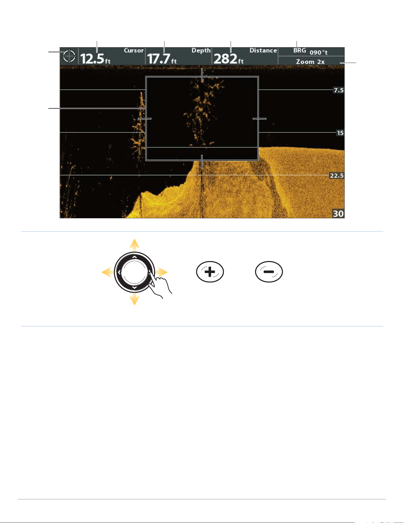
90
Down Imaging Sonar
ZOOM In ZOOM Out
Move the Cursor
cursor
digital
readouts
cursor depth distance to cursor position bearing to cursor position
Zooming into the Down Imaging History
zoom box
can be
moved with
the Cursor
Control key
depth below cursor
zoom level
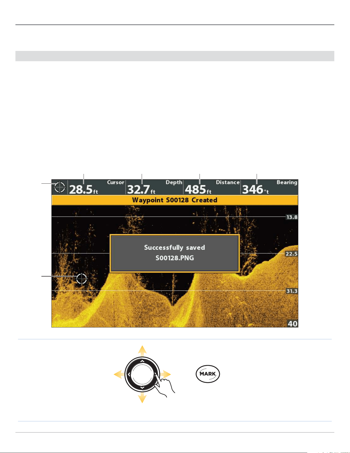
91
Down Imaging Sonar
Navigation in Down Imaging Views
To mark waypoints and start navigation, the control head must have a GPS Fix from a connected or internal GPS receiver. See
Getting Started for more information.
Mark a Waypoint
You can mark a waypoint at the boat position or the cursor position. Waypoints are saved to the Waypoint Management dialog box
(see Manage your Navigation Data).
Mark a Waypoint at the Boat Position
1. Press the MARK key.
Mark a Waypoint at the Cursor Position
1. Use the Cursor Control key to move the cursor to a position on the view.
2. Press the MARK key twice.
Press Twice to
Mark a Waypoint
Move the Cursor
cursor
digital
readouts
cursor depth
Marking a Waypoint at the Cursor Position
cursor
depth below cursor
distance to cursor position bearing to cursor position

92
Down Imaging Sonar
Navigate to a Position
Use the instructions in this section to start navigation to a position in the view. See Navigation Overview for more information
about these features.
Navigate to the Cursor Position
1. Use the Cursor Control key to move the cursor to a position on the view.
2. Press the GOTO key twice.
When you press the GOTO key, a waypoint will be marked at the cursor position.
Navigate to a Saved Position
If you press the GOTO key, you can choose to start navigation from a list of saved waypoints and routes.
1. Press the GOTO key.
2. Select Nav Data. Press the RIGHT Cursor key.
3. Use the Cursor Control key to select a saved waypoint or route.
4. Press the RIGHT Cursor key to start navigation.
Cancel Navigation
1. Press the MENU key once.
2. Select Cancel Navigation. Press the RIGHT Cursor key.
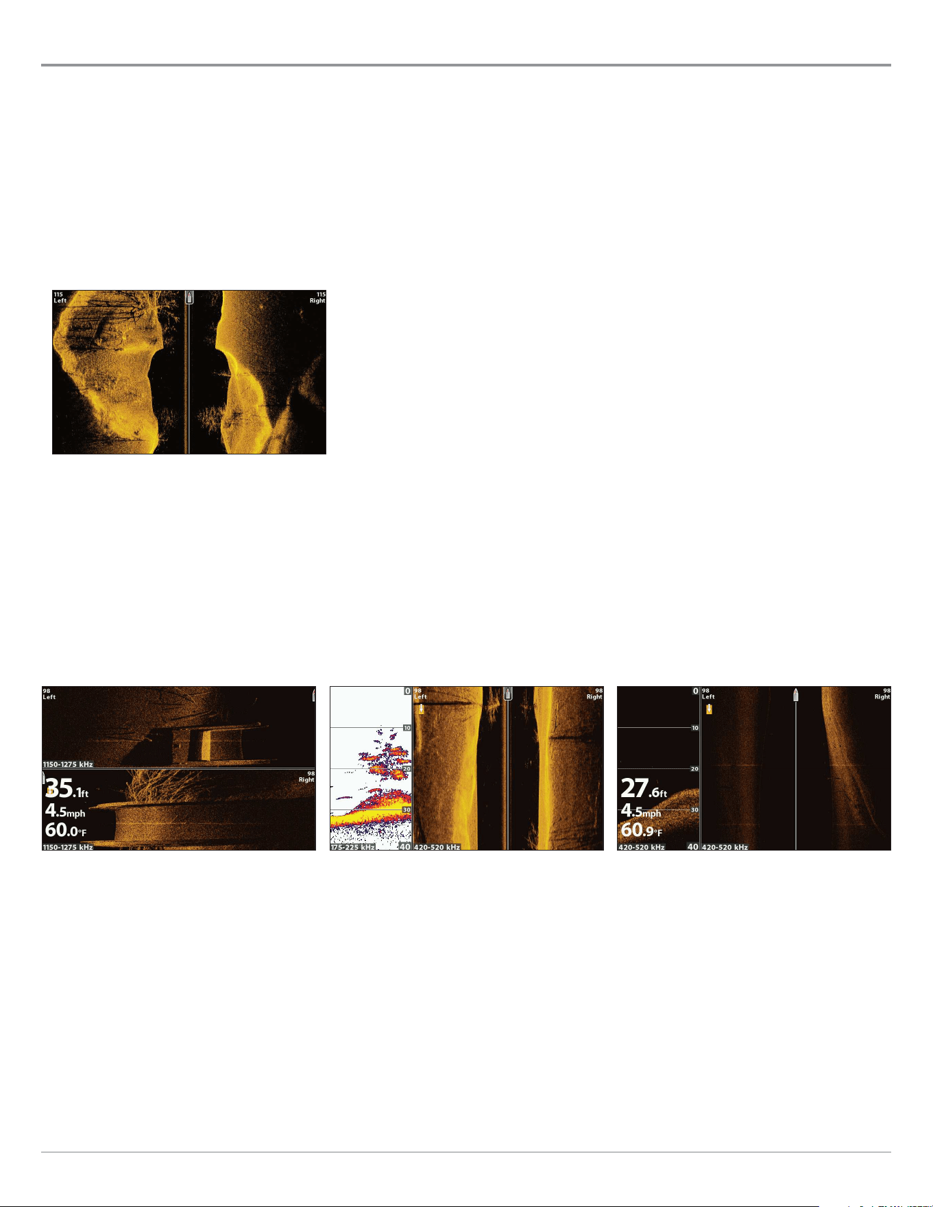
93
Side Imaging Sonar
Display a Side Imaging View On-Screen
(CHIRP SI, CHIRP MEGA SI, CHIRP MEGA SI+ only)
There are a variety of views available to display
Side
Imaging data. You can also customize the view by showing or hiding information
(see Customize the Side Imaging View), and you can adjust the sonar settings to maximize the information displayed on-screen
(see Adjust Settings While you Fish). The changes you make are applied to all Side Imaging views.
Display a Side Imaging View
1. Press and hold the VIEW key.
2. Select Sonar > Side Imaging View.
Side Imaging View
Display a Side Imaging Combo View
1. Press and hold the VIEW key.
2. To open a Side Imaging Combo View, select Sonar.
To open a Chart Combo View (Side Imaging and Chart together), select Chart.
3. Select a view to display on-screen. Press the RIGHT Cursor key.
Sonar > Down/Side Combo View
For more information, see
the Down Imaging section.
Sonar > Side/Sonar Combo View
For more information, see
the Sonar section.
Sonar > Side/Side Combo View
For more information, see
Adjust Settings While you Fish: Display Beams.
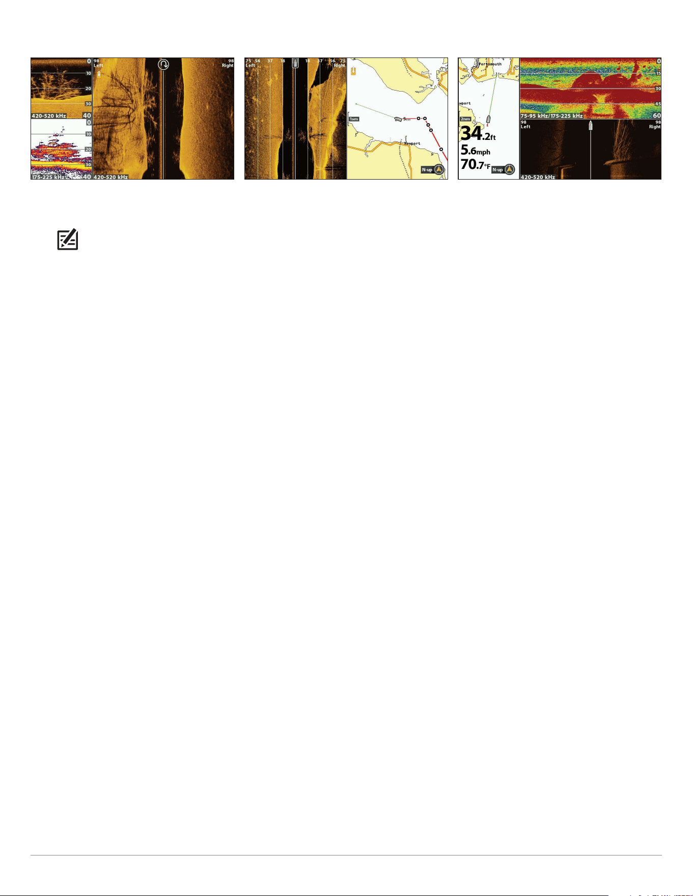
94
Side Imaging Sonar
For more information, see
the Sonar and Navigation sections.
Chart > Chart/Sonar/Side Combo View
(Map Source: Contour XD)
Chart > Chart/Side Combo View
(Map Source: Contour XD)
For more information, see
Navigation Overview.
Sonar > Down/Side/Sonar Combo View
For more information, see
the Sonar and Down Imaging sections.
NOTE: The available views are determined by your control head model and the installed transducer. For a complete list of the
views available on your control head, press the MENU key twice, and select the Views tab. See each related section of the manual
(Views, Sonar, Down Imaging, Navigation Overview, etc.) for more information.
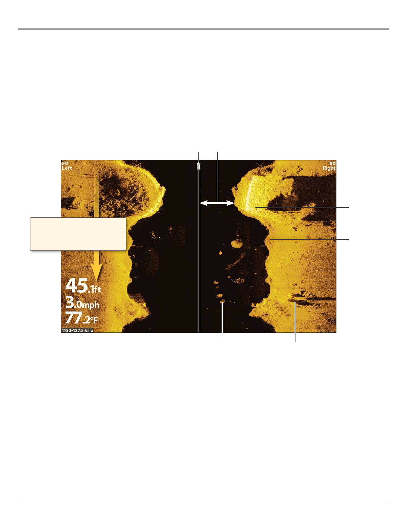
95
Side Imaging Sonar
Understand the Side Imaging View
Side Imaging beams “illuminate” the bottom contour, structure, and fish. The side beam coverage is very thin from front to back,
yet very wide from top to bottom. The bottom composition determines the intensity of the sonar return, and upward slopes that
face the transducer reflect sonar better than downward slopes that face away from the transducer.
For Best Side Imaging Performance
• Boat Speed: trolling
• Straight line navigation
• Minimum turning time and wave turbulence
Side Imaging View (CHIRP MEGA SI)
(HELIX 9 CHIRP SI GPS G2N)
boat icon
shadowswhite streaks
water column
dark shades
light shades
Side Imaging sonar returns are first
displayed at the top of the screen, and
historical data scrolls down the display
as new information is received.
Use the light and dark parts of the display to interpret the objects on the view as follows:
Shadows: The longer the shadow, the taller the object. Fish also cast shadows, and their distance from the bottom can be
interpreted by their shadow.
Light Shades represent denser terrain (possibly compacted sediment, timber, rocks) or rising terrain.
Water Column: shows the relative depth of the water under the boat at any given time. Variations in the width of the water
column show variations in the distance to the bottom as the boat passes over. See the illustration Interpreting the Side
Imaging View.
White Streaks or Clouds may represent fish on the display.
Dark Shades represent soft returns (possibly sand or mud) or descending terrain.
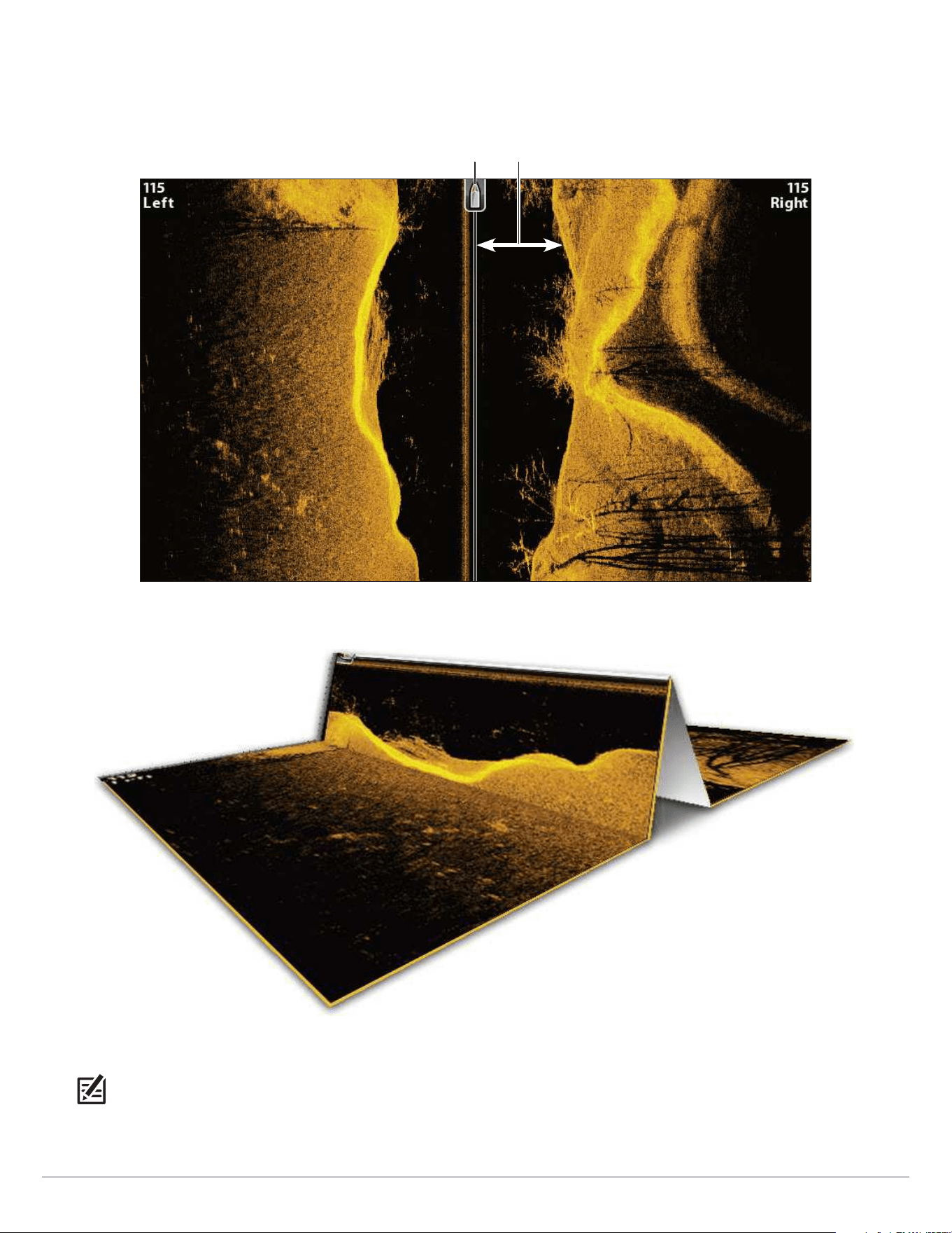
96
Side Imaging Sonar
To visualize how Side Imaging works, the Side Imaging View illustration can be folded down the middle and then folded again at the
lowest point of the water column. The raised area reveals the water column with its relative depth of the water under the boat. In the
Side Imaging View, variations in the width of the water column show variations in the distance to the bottom as the boat passes over.
Side Imaging View
boat icon water column
Interpreting the Side Imaging View
NOTE: See humminbird.com for tutorials and Side Imaging videos.
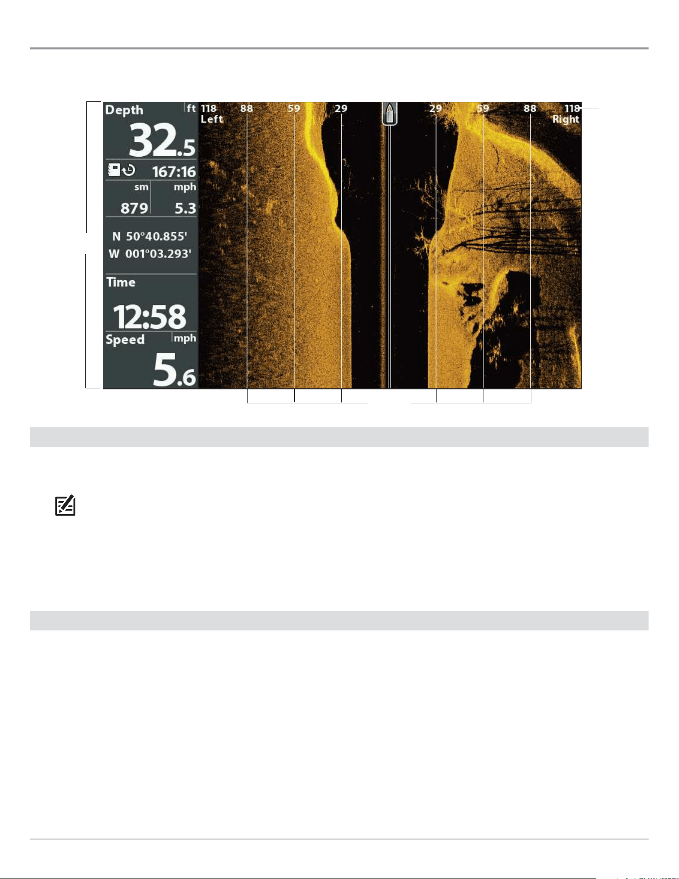
97
Side Imaging Sonar
Customize the Side Imaging View
The settings in this section are optional. You can use the default settings for the view, or you can customize it with your preferences.
range lines
Showing Digital Readouts and SI Range Lines
digital readouts
set to boxes
range
numbers
Show/Hide SI Range Lines
SI Range Lines divide each side beam range into equal sections on the Side Imaging View. Use the range lines to estimate the
location of objects. You can show or hide range lines on the view.
NOTE: The range numbers are estimated and should not be used for measurement. If SI Range Lines and Contour Mode are turned
on, the SI Range Lines will remain on the display, but the individual range numbers will not be available.
1. Main Menu: Press the MENU key twice. Select the Sonar tab.
2. Select SI Range Lines.
3. Select On (show) or Off (hide).
Show/Hide Digital Readouts on the Side Imaging View
If you have Digital Readouts set to Boxes on all views, you can hide the digital readout boxes on the Side Imaging View exclusively.
For details, see Views: Display Digital Readouts.
1. Main Menu: Press the MENU key twice. Select the Sonar tab.
2. Select SI Readouts.
3. Select On (show) or Off (hide).

98
Side Imaging Sonar
Change the View Colors
The SI Colors menu changes the colors used to display sonar returns on the view.
1. Side Imaging X-Press Menu: With a Side Imaging View displayed on-screen, press the MENU key once.
2. Select SI Colors.
3. Select a palette.
Side Imaging View with Palette 1 Displayed
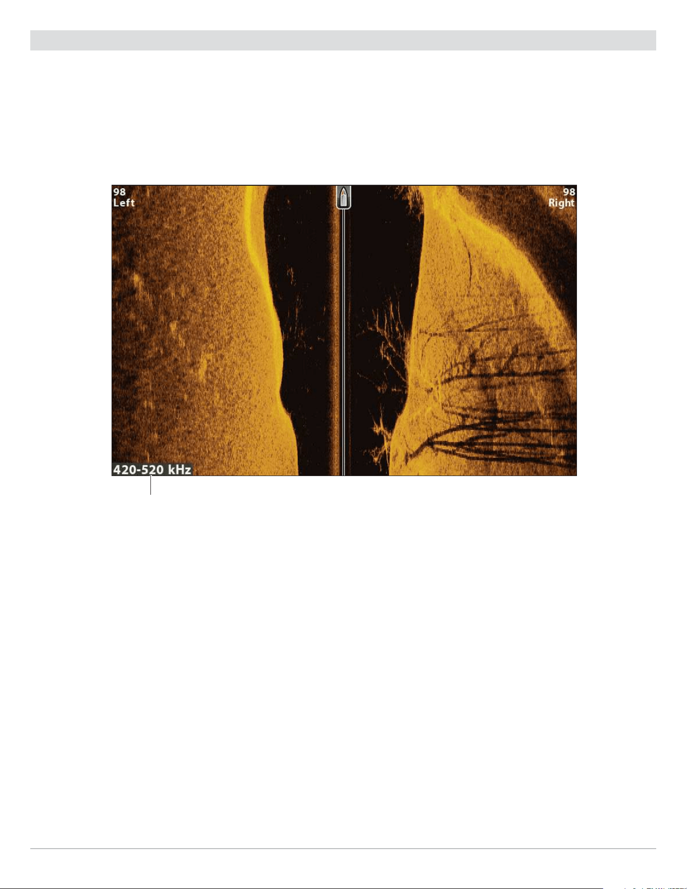
99
Side Imaging Sonar
Show/Hide the Frequency Label
The Frequency Label displays the currently selected frequencies. See Set up Sonar.
1. Main Menu: Press the MENU key twice. Select the Sonar tab.
2. Select Frequency Label.
3. Select On (show) or Off (hide).
Side Imaging View with the Frequency Label Turned On
selected display
frequency

100
Side Imaging Sonar
Adjust Settings while you Fish
(Side Imaging X-Press Menu)
The X-Press Menu provides menu options to adjust the sensitivity and range as you fish. You can also control how fast the sonar
history scrolls down the screen. The menu options allow you to see more or less of the sonar returns from the transducer beams
as you adjust each setting. Also, you can use key shortcuts on the view.
Adjust Sensitivity
Sensitivity controls how much detail is shown on the view. You can adjust sensitivity from the X-Press Menu or the Enhance menu
(see Enhance the Side Imaging View). The sensitivity can also be adjusted using the +/− ZOOM keys.
Decrease the sensitivity to eliminate the clutter from the display that is sometimes present in murky or muddy water. When
operating in very clear water or greater depths, increase the sensitivity to see weaker returns.
Adjust the Sensitivity using the X-Press Menu
1. Side Imaging X-Press Menu: With a Side Imaging View displayed on-screen, press the MENU key once.
2. Select SI Sensitivity.
3. Press the RIGHT or LEFT Cursor keys to increase or decrease the sensitivity.
Adjust the Sensitivity using the ZOOM Keys
If your control head includes +/−ZOOM keys, you can use them to adjust the sensitivity.
1. With a Sonar View displayed on-screen, press the +ZOOM key or −ZOOM key.
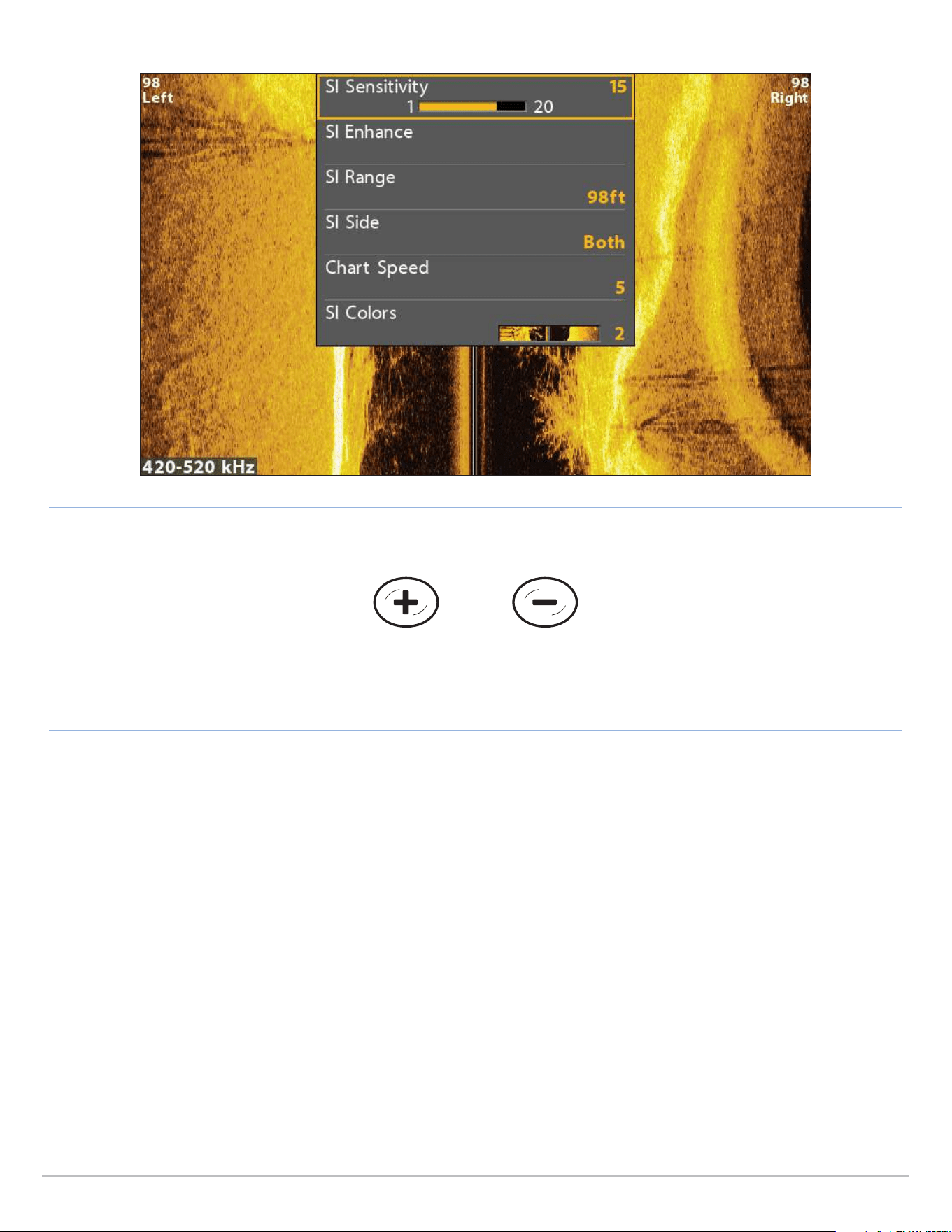
101
Side Imaging Sonar
Decrease SensitivityIncrease Sensitivity
Adjusting the Sensitivity using the +/−ZOOM Keys
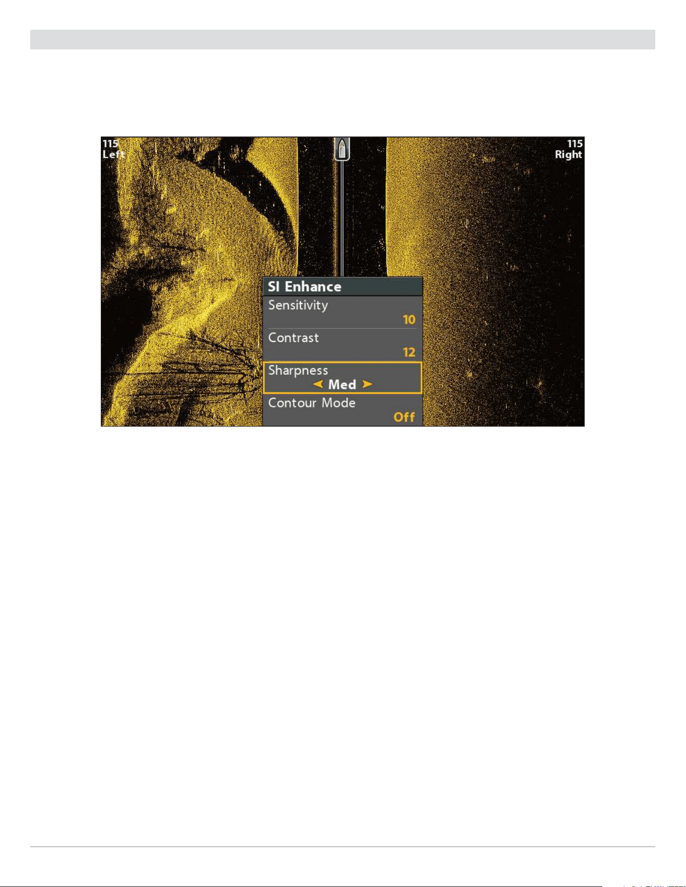
102
Side Imaging Sonar
Enhance the Side Imaging View
The SI Enhance menu allows you to adjust the sensitivity, contrast, and sharpness on the Side Imaging View. As you adjust each
setting, the changes are displayed immediately on the view, so you can fine tune the display. You can also turn on/off the Contour
Mode from this menu so the water column is displayed or hidden on the view.
Enhancing the Side Imaging View
Enhance the Side Imaging View
1. Side Imaging X-Press Menu: With a Side Imaging View displayed on-screen, press the MENU key once.
2. Select SI Enhance. Press the RIGHT Cursor key.
3. Use the Cursor Control key to select each menu and adjust the setting.
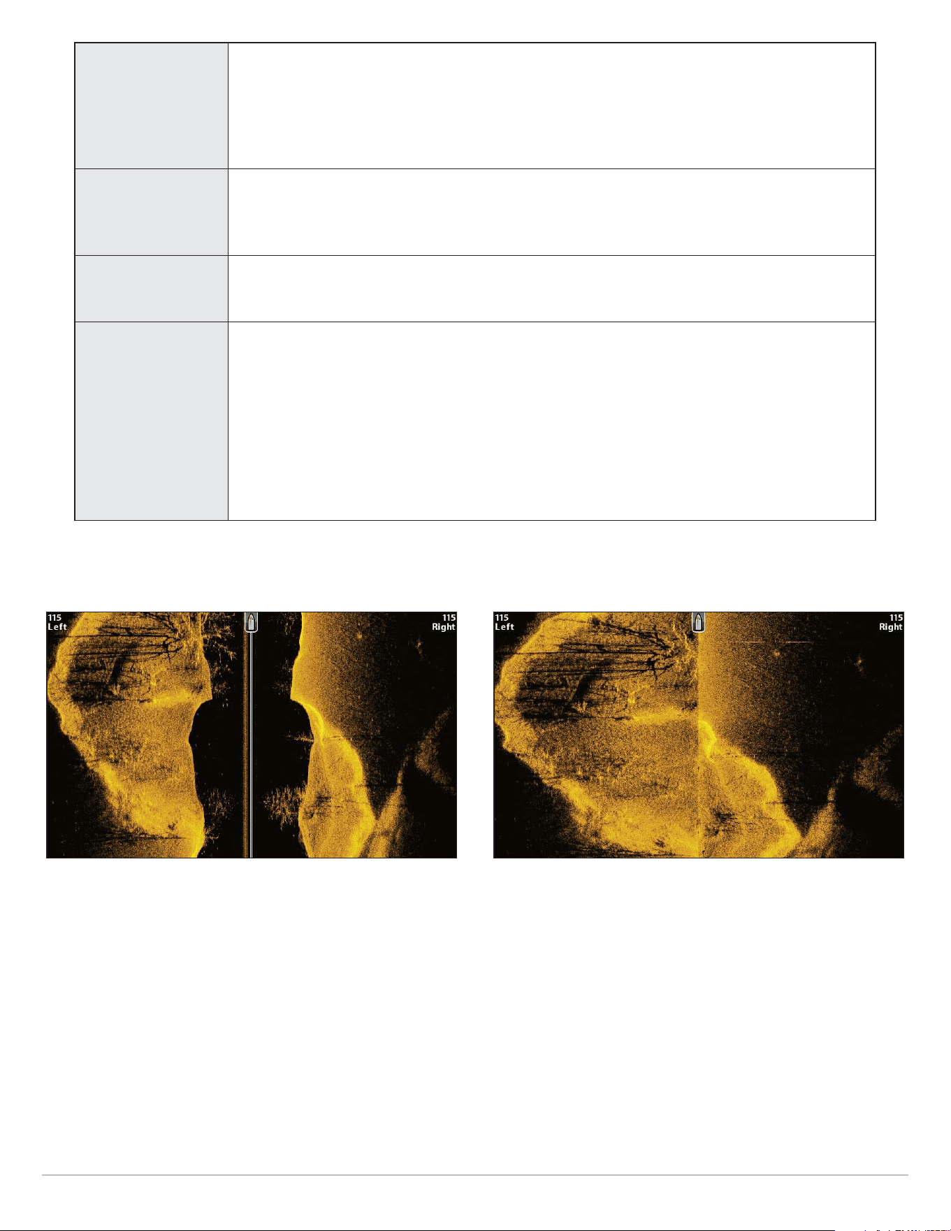
103
Side Imaging Sonar
Sensitivity
Sensitivity controls how much detail is shown on the view. Decrease the sensitivity to
eliminate the clutter from the display that is sometimes present in murky or muddy water.
When operating in very clear water or greater depths, increase the sensitivity to see weaker
returns that may be of interest. This menu can also be adjusted from the Side Imaging X-Press
Menu (SI Sensitivity).
Contrast
Adjust the Contrast setting to accent the light and dark parts of the Side Imaging data to
provide greater definition. To intensify the strong returns, increase the contrast. To intensify
the weak returns, decrease the contrast.
Sharpness Turn on sharpness and select a filter level to sharpen the edges of the Side Imaging data.
Contour Mode
Contour Mode controls how the water column is displayed in the Side Imaging Views. When
Contour Mode is turned off, the water column is displayed on the view. The location of a target
on the display is based on the slant range to the target.
When Contour Mode is turned on, the bottom is graphed at a constant point on the display,
regardless of changes in depth. The Side Imaging beams are divided by a vertical line. The
water column is removed from the view, which allows the display to show targets at their
linear horizontal distance. The location of a target may be easier to interpret when the water
column is removed.
Contour Mode Off Contour Mode On
The water column is displayed on the Side Imaging View. The water column is removed from the Side Imaging View.
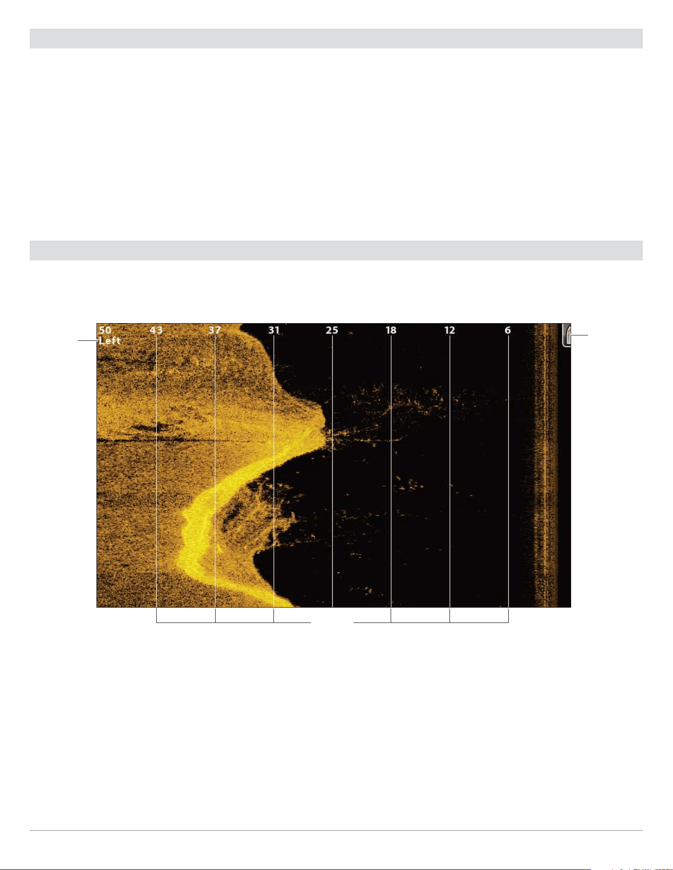
104
Side Imaging Sonar
Adjust the Side Imaging Range
SI Range sets the deepest range that will be displayed on the Side Imaging views.
Choose
a low range number to focus on a shorter
distance of the water column and see greater detail on the view. Choose a higher range number to see farther into the water and
see an overview of details on the screen.
1. Side Imaging X-Press Menu: With a Side Imaging View displayed on-screen, press the MENU key once.
2. Select SI Range.
Auto: The Range will be adjusted by the control head to follow the bottom automatically.
Manual: The control head locks onto the depth you select.
Side Imaging units default to the Side Imaging range setting if the SI Range is set deeper than the Max Depth. See Set up Sonar
for more information.
Display Beams
Use SI Side to select which Side Imaging beam will be shown on the display.
Side Imaging View with the Left Beam Displayed
range lines
boat icon
left beam
label
Select Beams to Display on the View
1. Side Imaging X-Press Menu: With a Side Imaging View displayed on-screen, press the MENU key once.
2. Select SI Side.
3. Select a beam or both beams to display.
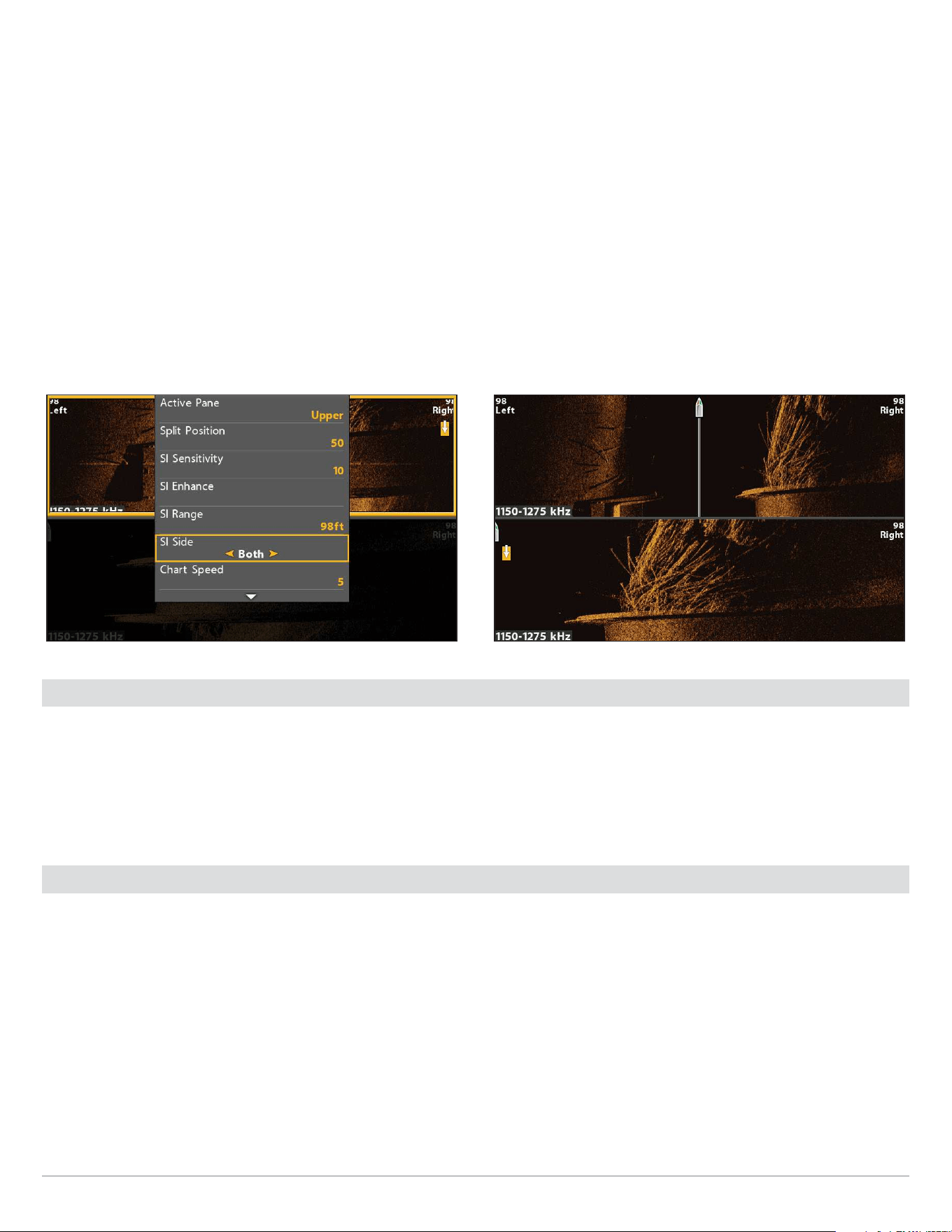
105
Side Imaging Sonar
Select Beams to Display on the Side/Side Combo View
Use the Side/Side Combo View to focus on each side or one side.
1. Press and hold the VIEW key.
2. Select Sonar > Side/Side Combo View.
3. Press the RIGHT Cursor key.
4. X-Press Menu: Press the MENU key once.
5. Select Active Pane.
6. Select Upper or Lower.
7. Select SI Side.
8. Select a beam or both beams to display.
Selecting Both Beams for the Upper Active Pane Side/Side Combo View (CHIRP MEGA SI)
Change the Chart Speed
Chart Speed controls how fast the sonar history moves down the view and how much detail is shown.
1. Side Imaging X-Press Menu: With a Side Imaging View displayed on-screen, press the MENU key once.
2. Select Chart Speed.
3. Press the RIGHT or LEFT Cursor keys to adjust the setting.
Change the View Colors
The Side Imaging X-Press Menu allows you to quickly change the display palette while you fish. See Customize the Side Imaging
View: Change the View Colors for more information.
1. Side Imaging X-Press Menu: With a Side Imaging View displayed on-screen, press the MENU key once.
2. Select SI Colors.
3. Select a palette.
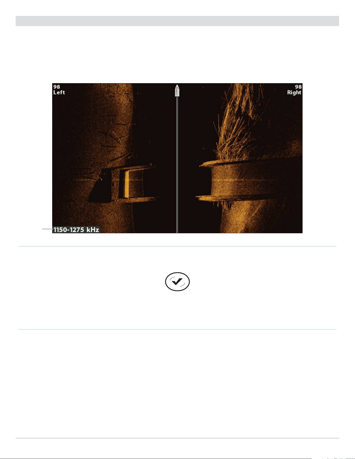
106
Side Imaging Sonar
Switch Frequencies (CHIRP MEGA SI, CHIRP MEGA SI+ models only)
If the transducer includes more than one Side Imaging frequency, use the CHECK/INFO key to quickly change the frequency used
in the Side Imaging View. For more information see Sonar Overview and Set up Sonar.
1. With a Side Imaging View displayed on-screen, press the CHECK/INFO key.
Switch Frequencies
Using the CHECK key to Switch Frequencies (CHIRP MEGA SI)
(HELIX 9 CHIRP SI GPS G2N)
frequency
label

107
Side Imaging Sonar
Review Side Imaging History and Zoom In/Out
In addition to adjusting the sonar settings while you fish, you can freeze the sonar history, magnify sonar returns, and review
position information.
Freeze the Side Imaging View
Press any arrow on the Cursor Control key, and the sonar history will freeze and the cursor will display on-screen. If you move the
cursor over a sonar return, digital readouts for the cursor position are displayed on the view.
1. Press any arrow on the Cursor Control key.
2. Move the cursor over a sonar return.
3. Review the cursor position and depth information in the digital readouts.
NOTE: To mark a waypoint or start navigation to the cursor position, see Navigation in Side Imaging Views.
Zoom In/Zoom Out
To take a closer look, use the ZOOM keys to magnify the selected part of the view.
1. Use the Cursor Control key to move the cursor to a position on the view.
2. Zoom In: Press the +ZOOM key.
Zoom Out: Press the -ZOOM key.
3. Close: Press the EXIT key.
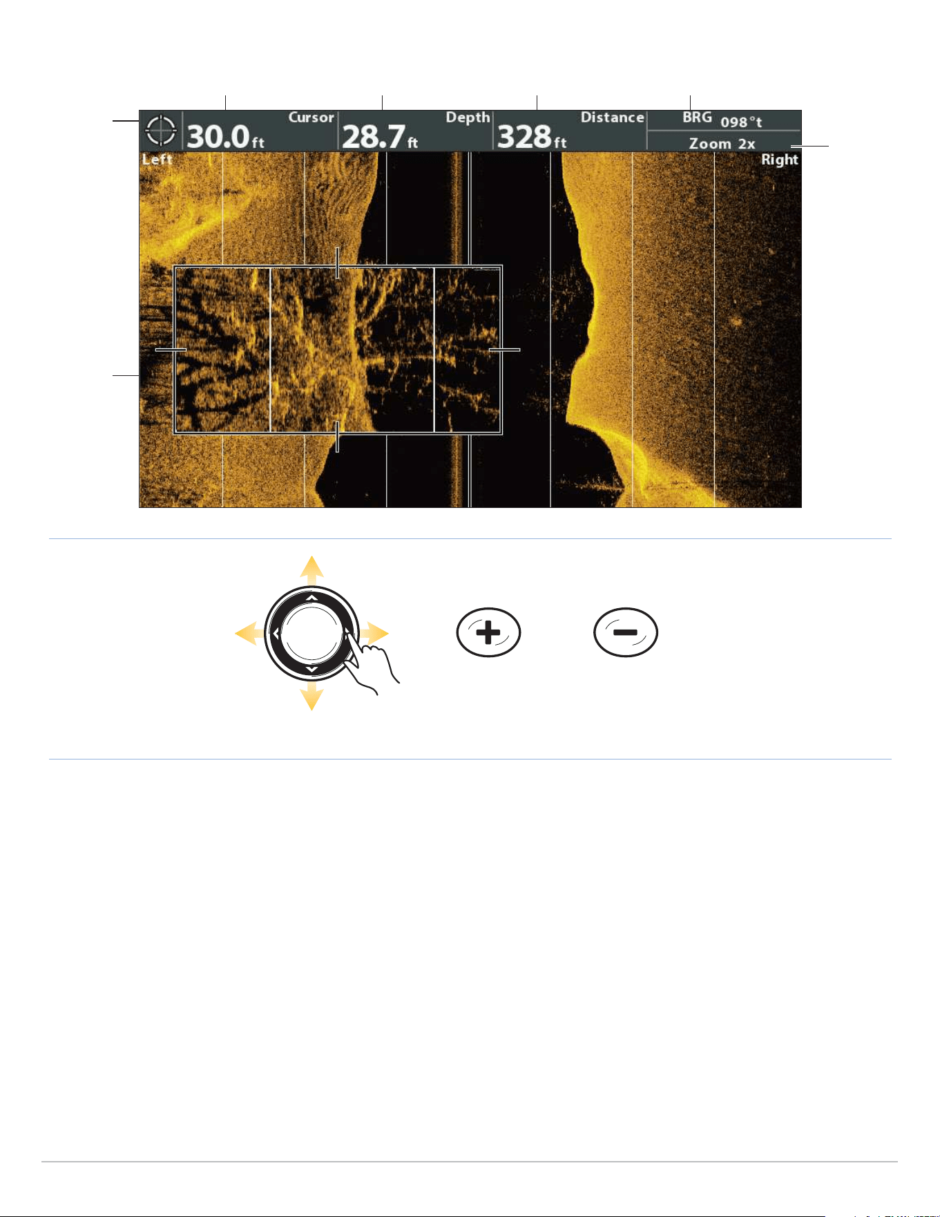
108
Side Imaging Sonar
ZOOM In ZOOM Out
Move the Cursor
cursor
digital
readouts
cursor depth distance to cursor position bearing to cursor position
Zooming In/Out
zoom box
can be
moved with
the Cursor
Control key
depth below cursor
zoom level

109
Side Imaging Sonar
Navigation in Side Imaging Views
To mark waypoints and start navigation, the control head must have a GPS Fix from a connected or internal GPS receiver. See
Getting Started for more information.
Turn on/o SI Navigation
SI Navigation controls how the boat icon is displayed in Side Imaging Views. See Navigate to a Position for more information.
If SI Navigation is turned on, an arrow icon indicates the direction the boat needs to turn to reach the next waypoint during
navigation.
If SI Navigation is turned off, the boat icon will not change during navigation although you can still mark waypoints and start
navigation from a Side Imaging View.
1. Main Menu: Press the MENU key twice. Select the Nav tab.
2. Select SI Navigation.
3. Select On or Off.
Mark a Waypoint
You can mark a waypoint at the boat position or the cursor position. Waypoints are saved to the Waypoint Management dialog box
(see Manage your Navigation Data).
Mark a Waypoint at the Boat Position
1. Press the MARK key.
Mark a Waypoint at the Cursor Position
1. Use the Cursor Control key to move the cursor to a position on the view.
2. Press the MARK key twice.
Navigate to a Position
Use the instructions in this section to start navigation to a position in the view. See Navigation Overview for more information
about these features.
Navigate to the Cursor Position
1. Use the Cursor Control key to move the cursor to a position on the view.
2. Press the GOTO key twice.
When you press the GOTO key, a waypoint will be marked at the cursor position.
Navigate to a Saved Position
If you press the GOTO key, you can choose to start navigation from a list of saved waypoints and routes.
1. Press the GOTO key.
2. Select Nav Data. Press the RIGHT Cursor key.
3. Use the Cursor Control key to select a saved waypoint or route.
4. Press the RIGHT Cursor key to start navigation.
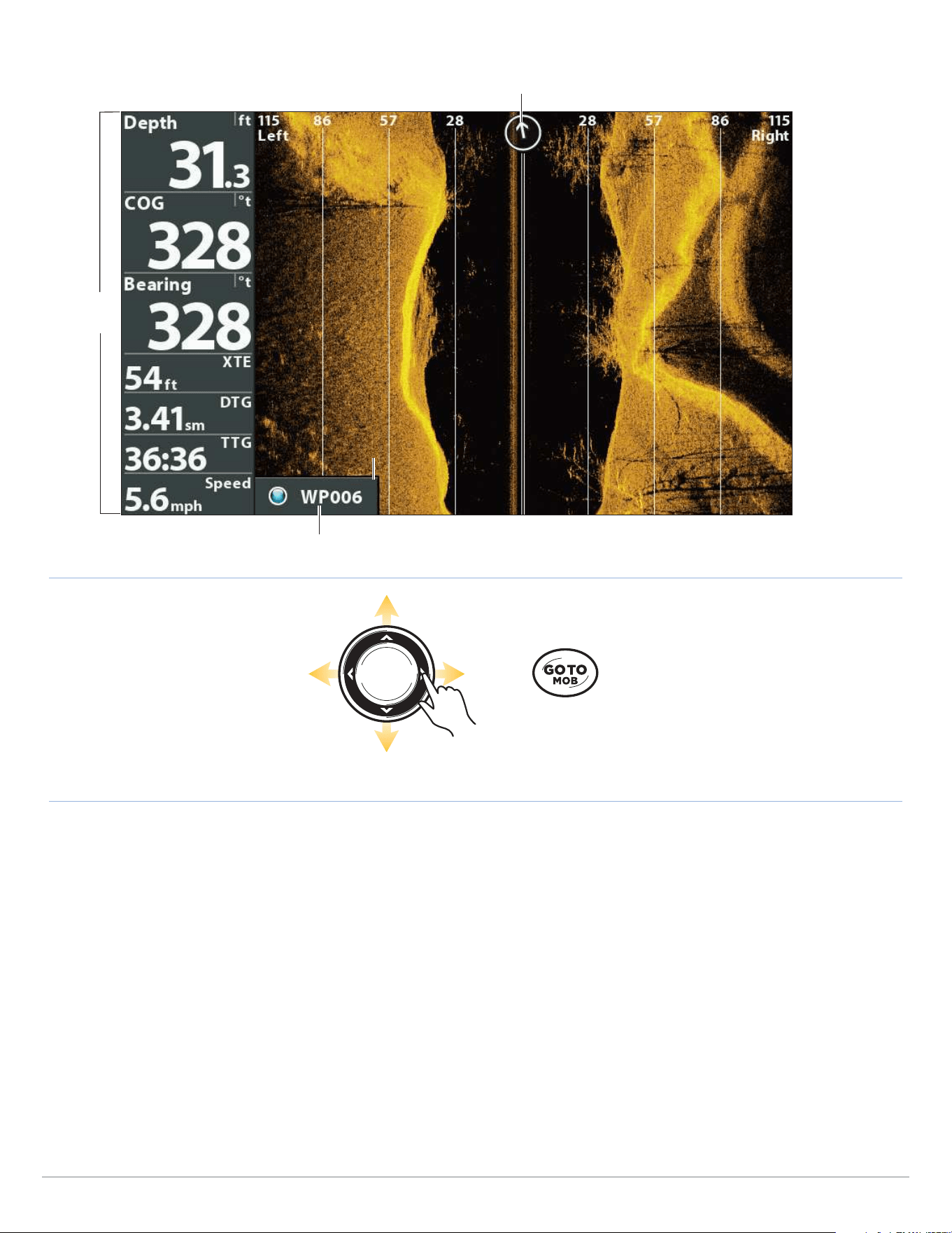
110
Side Imaging Sonar
Navigating to a Waypoint
direction to turn the boat to reach the next waypoint (SI Navigation On)
navigation
digital
readouts
next waypoint
Press Twice to
Start Navigation
Move the Cursor
Cancel Navigation
1. Press the MENU key once.
2. Select Cancel Navigation. Press the RIGHT Cursor key.
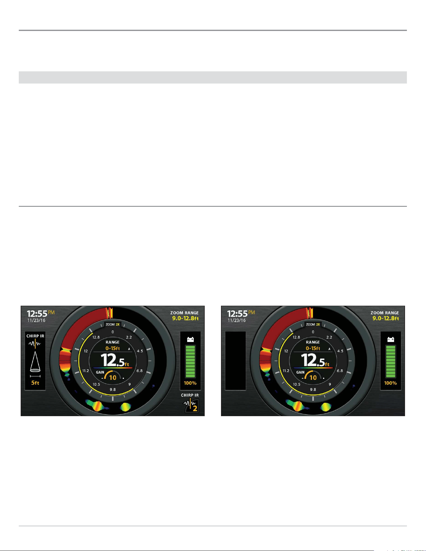
111
Ice Fishing
Ice Fishing Overview
Ice Fishing mode is available on ICE HELIX models and any HELIX 5, 7, 8, 9 or 10 model with the latest software update. If you have
a compatible model and want to use it for ice fishing, Ice Fishing mode must be turned on. To enable Ice Fishing mode, see the
instructions below.
Turn on Ice Fishing Mode
If you have an ICE HELIX CHIRP model, proceed to Display the Flasher View On-Screen.
1. Preparation: Confirm your control head software is up to date. See Update Software.
2. Main Menu: Press the MENU key twice. Select the Sonar tab.
3 Select Ice Fishing.
4. Press the RIGHT Cursor key.
The control head will automatically restart.
To return to Open Water mode, repeat step 2 and select Open Water.
Display the Flasher View On-Screen
Flasher View provides two ways to view sonar data in traditional flasher format. The view is available on compatible models with Ice
Fishing mode turned on.
Display the Flasher View
1. Press and hold the VIEW key.
2. Select Sonar > Flasher View.
Flasher View with CHIRP IR Turned On
(CHIRP models only)
Flasher View
(HELIX models without CHIRP)
Select the Digital Depth Source (DI, CHIRP DI models only)
If you connect an ice transducer to the HELIX DI G2, HELIX CHIRP DI G2, or HELIX CHIRP DI GPS G2/G2N control head, set the Digital
Depth Source to 2D Element. See Set up Sonar for details.
1. Main Menu (Custom User Mode): Press the MENU key twice. Select the Sonar tab.
2. Select Digital Depth Source.
3. Select 2D Element.
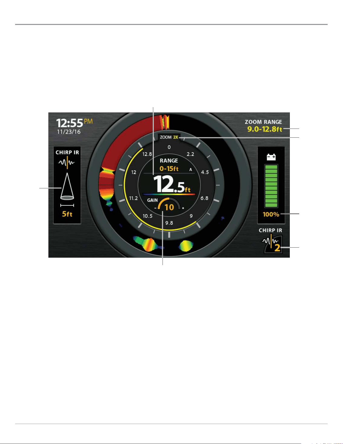
112
Ice Fishing
Understand the Flasher View
Like a traditional sonar view, the Flasher View displays the sonar return intensity with different colors. The view is maximized with
information you need for ice fishing, including the current depth, connected battery power percentage, and related menu settings.
Strong returns often result from rocky or hard bottoms (compacted sediment, rocks, fallen trees), while weaker returns often result
from soft bottoms (sand, mud), vegetation, and small fish.
The colors used to represent high, medium, to low intensity returns are determined by the palette you choose (see Adjust Settings
While you Fish: Change the Sonar Colors Palette).
Flasher View (ICE HELIX 7 CHIRP)
zoom level
Related menu settings are displayed in the center of the flasher view and include the current depth range and lower
range mode indicator (Auto [A] or Manual [M]), sonar color palette, and gain.
percentage
of power for
connected
battery
cone angle
zoom range
current depth reading
CHIRP IR
setting
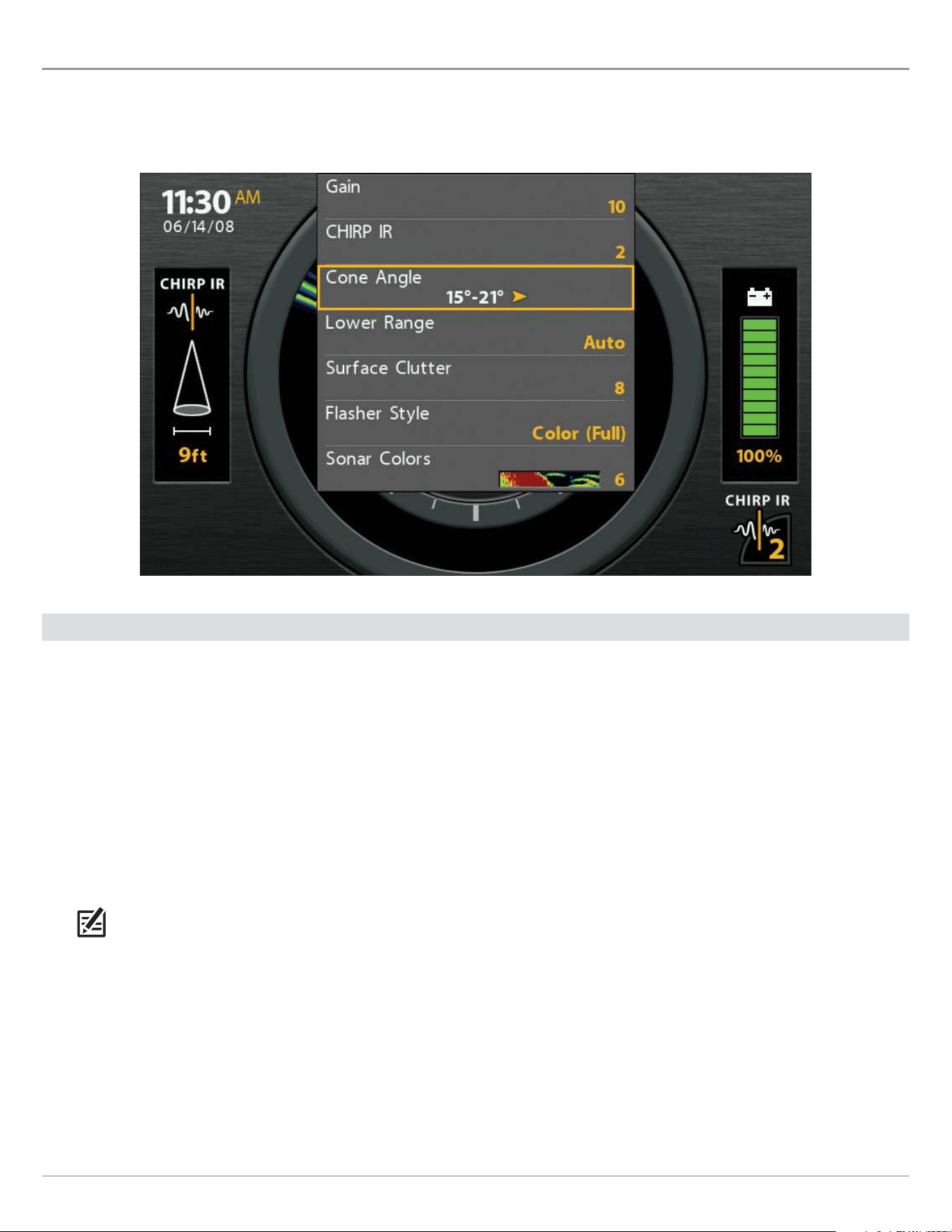
113
Ice Fishing
Adjust Settings while you Fish
The X-Press Menu provides menu options to adjust the sensitivity and range as you fish. The menus allow you to see more or less
of the sonar returns from the transducer beams as you adjust each setting. Also, you can use key shortcuts on the views.
Adjusting Settings from the X-Press Menu (ICE HELIX 7 CHIRP)
Adjust the Gain (Sensitivity)
Gain (or Sensitivity, depending on your control head model) controls how much detail is shown on the view. To eliminate the clutter
from the display that is sometimes present in murky or muddy water, decrease the gain. When operating in very clear water or
greater depths, increase the gain to see weaker returns.
Adjust the Gain using the X-Press Menu
Use the following instructions to adjust the gain.
1. Flasher X-Press Menu: With the Flasher View displayed on-screen, press the MENU key once.
2. Select Gain.
3. Press the RIGHT or LEFT Cursor keys to increase or decrease the gain.
KEY SHORTCUT: In Sonar View, press the +ZOOM key to increase the gain and the -ZOOM key to decrease the gain (GPS models
only).
114
Ice Fishing
Adjust for Interference (CHIRP models only)
If you are fishing near other ICE flashers or transducers, use CHIRP IR (Interference Rejection) to reduce interference or noise on
the sonar display.
Set the CHIRP Interference Rejection (CHIRP IR) using the X-Press Menu
1. Flasher X-Press Menu: With the Flasher View displayed on-screen, press the MENU key once.
2. Select CHIRP IR.
3. Press the RIGHT or LEFT Cursor keys to adjust the setting.
KEY SHORTCUT: With the Flasher View displayed on-screen, press the CHECK/INFO key to adjust the CHIRP IR setting (GPS models
only).
Set the Cone Angle (CHIRP models only)
Use the following instructions to set the angle of the sonar beam. CHIRP IR must be turned off to set the Cone Angle.
1. Flasher X-Press Menu: With the Flasher View displayed on-screen, press the MENU key once.
2. Select Cone Angle.
3. Press the RIGHT or LEFT Cursor keys to adjust the setting.
15° Select 15° for a narrowly focused down beam.
21° Select 21° for a wide down beam and larger coverage area.
15°-21° Select 15°-21° to use the full frequency range for your transducer.
Set the Upper/Lower Range
Upper Range and Lower Range control how much of the water column is displayed on the view. For example, if you are only
interested in the area between 20 and 50 feet deep, set the Upper Range to 20 and the Lower Range to 50. The view will not display
sonar returns outside of the set ranges, and greater detail for the selected range will be displayed.
1. Flasher X-Press Menu: With the Flasher View displayed on-screen, press the MENU key once.
2. Select Upper Range. Press the RIGHT or LEFT Cursor keys to adjust the setting.
3. Select Lower Range. Select Auto or set a specific depth (manual).
Auto: The Lower Range will be adjusted by the control head to follow the bottom automatically.
Manual : The control head locks onto the depth you select.
NOTE: There must be a difference of 10 feet between the upper and lower range settings.
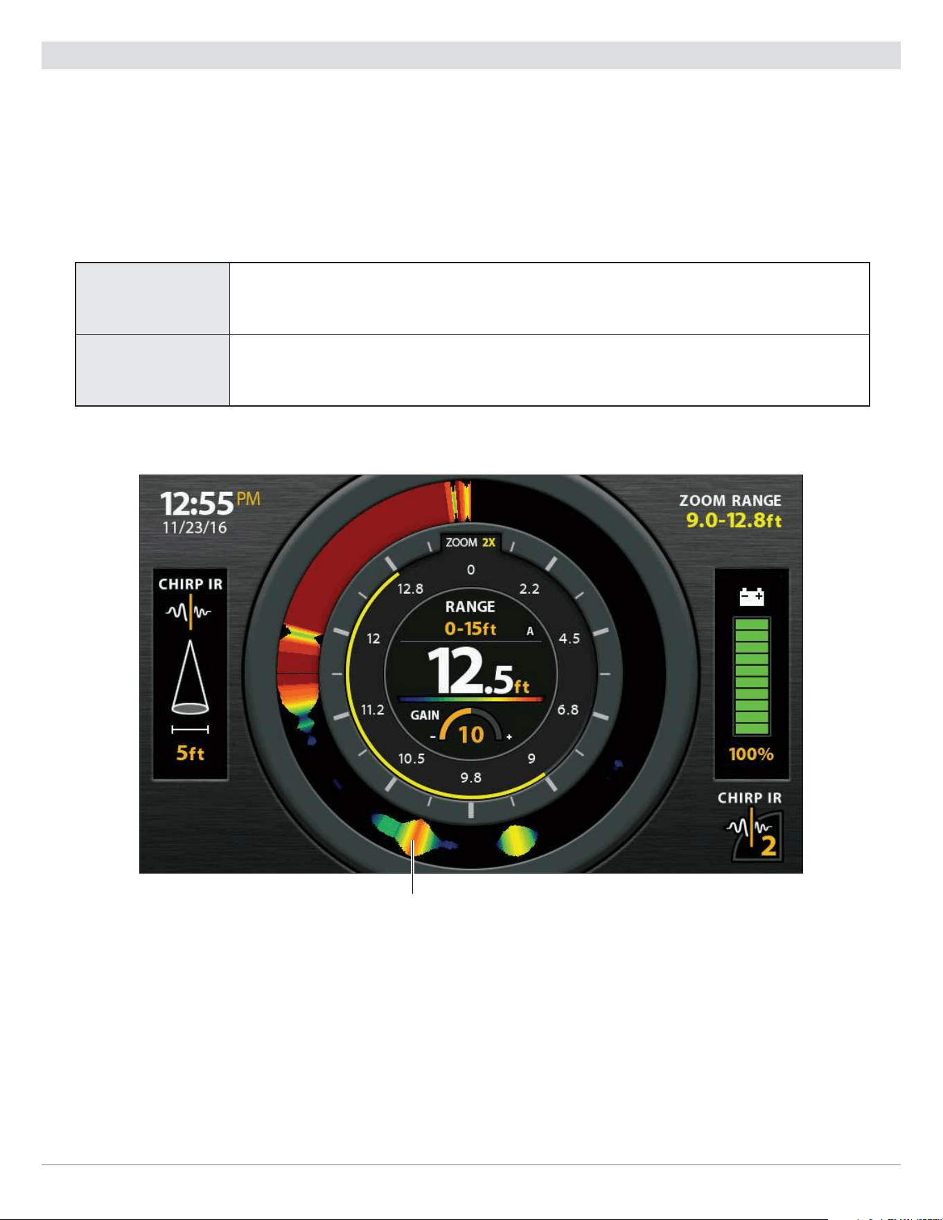
115
Ice Fishing
Change the Flasher Window Style
The Flasher Window displays the depth and intensity of the sonar returns. You can change the display style for the sonar returns
using the instructions below. You can also change the sonar colors used for sonar returns. For details, see Change the Sonar Colors
Palette.
1. Flasher X-Press Menu: With the Flasher View displayed on-screen, press the MENU key once.
2. Select Flasher Style.
3. Select the type of Flasher Style to display.
Color (Full) Sonar returns are displayed in color, and they fill the width of the Flasher Window.
Color (A-Scope)
Sonar returns are displayed in color. The size of the displayed lines correspond with the intensity
of the sonar returns from the transducer beam(s).
Flasher Style Set to Color (A-Scope)
The size of the sonar returns correspond with the intensity of the sonar returns from the transducer beam(s).

116
Ice Fishing
Select a Range of the Palette (Contrast)
Contrast allows you to choose a range of the Color Palette to display sonar returns. For details, see Change the Sonar Colors
Palette.
When Contrast is set to 20 (default), the entire palette is used to display weak and strong sonar returns. As you increase the
Contrast, fewer colors within the selected palette are used to display the sonar returns (whether weak or strong).
1. Main Menu (Custom User Mode): Press the MENU key twice. Select the Sonar tab.
2. Select Contrast.
3. Press the RIGHT or LEFT Cursor keys to increase or decrease the contrast.
Change the Sonar Colors Palette
The X-Press Menu allows you to quickly change the display palette while you fish. The Color Palette menu shows a preview of the
palette, and the weak to strong sonar return range is displayed from left to right.
1. Flasher X-Press Menu: With the Flasher View displayed on-screen, press the MENU key once.
2. Select Sonar Colors.
3. Select a palette.
Switch Frequencies
(key shortcut for GPS models only)
If the transducer includes more than one down beam frequency, use the CHECK/INFO key to quickly change the frequency used in
the Flasher View. For more information see Set up Sonar.
1. Press the CHECK/INFO key.
Change Battery Type
Your control head will automatically select the battery type that was included with your ICE HELIX control head. If you have purchased
a battery separately, select the connected battery type in the system so that your battery level reading is accurate.
1. Main Menu: Press the MENU key twice. Select the Setup tab.
2. Select Battery Type.
3. Press the RIGHT or LEFT Cursor keys to change battery types.
12V Lead Acid Default battery type for ICE HELIX 5 models.
11.1V Lithium NMC Default battery type for ICE HELIX 7 models.
14.8V Lithium NMC Default battery type for ICE HELIX 8, 9 and 10 models.
12V Lithium LFP Not a default battery type.
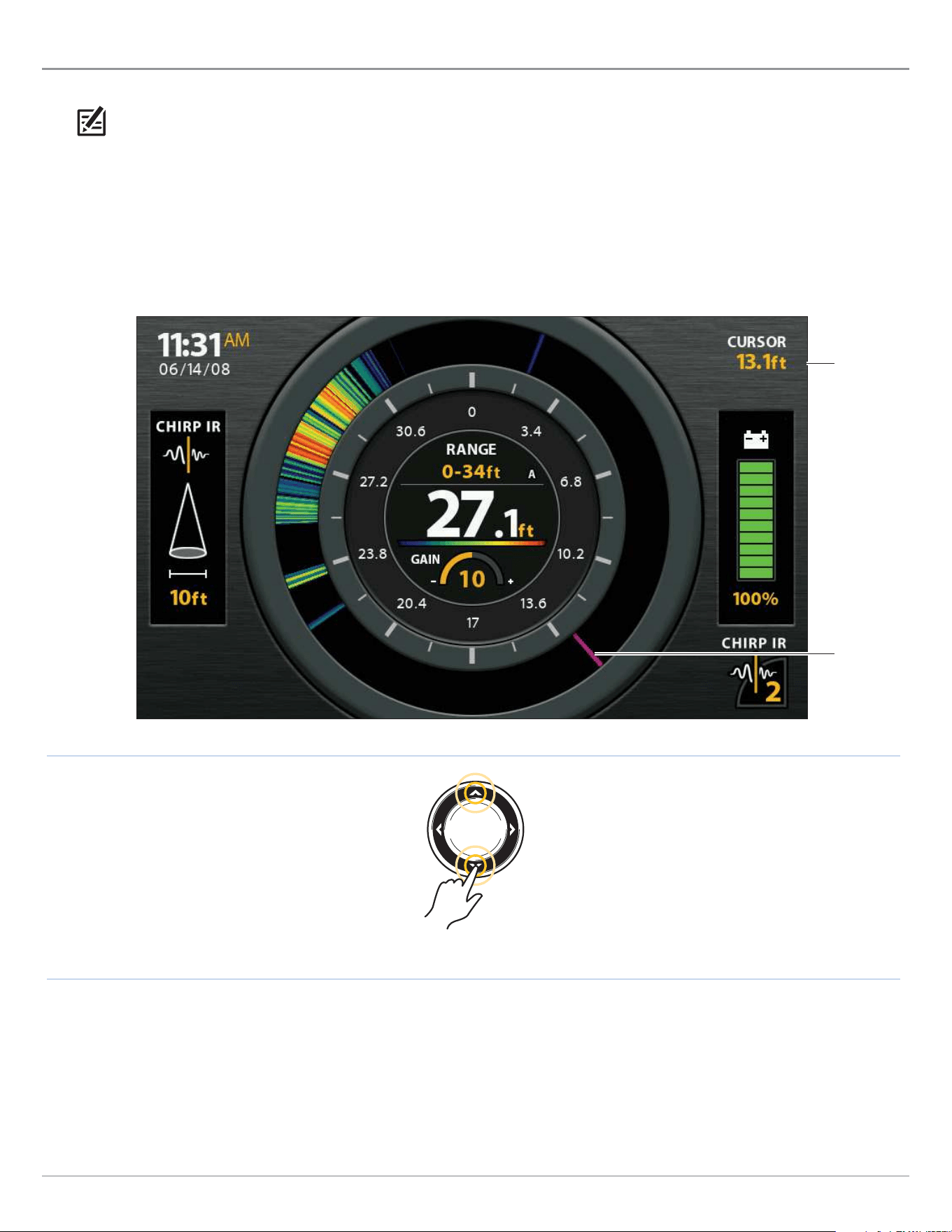
117
Ice Fishing
Move the Depth Cursor
Use the Depth Cursor to identify a depth on the Flasher View.
NOTE: Ice Fishing Mode must be turned on to enable this feature (see Ice Fishing Overview: Turn on Ice Fishing Mode).
1. Activate: Press the DOWN Cursor key, and the purple cursor line will display on the dial.
2. Adjust the Cursor: Press the UP or DOWN Cursor keys.
3. EXIT: Press the EXIT key.
depth cursor
setting
depth cursor
(purple line)
Flasher View with Depth Cursor Displayed
Move the Cursor

118
Ice Fishing
Zoom In/Out in Flasher View
The Zoom feature displays a 2x magnified view of the area you choose on the Flasher View.
NOTE: Ice Fishing Mode must be turned on to enable this feature (see Ice Fishing Overview: Turn on Ice Fishing Mode).
ZOOM In/Out using the ZOOM Keys (GPS models only)
1. Activate: Press the +ZOOM key.
2. Adjust the Zoom Range: Press the RIGHT or LEFT Cursor keys to move the white zoom lines on the flasher dial.
3. Close Zoom: Press -ZOOM key.
ZOOM In/Out using the Flasher X-Press Menu
If your control head model does not include ZOOM keys, you will use the Zoom Level menu.
1. Flasher X-Press Menu: With the Flasher View displayed on-screen, press the MENU key once.
2. Select Zoom Level.
3. Select 2X.
4. Adjust the Zoom Range: Press the RIGHT or LEFT Cursor keys to move the white zoom lines on the flasher dial.
5. Close Zoom: Press the MENU key. Select Zoom Level > 1X.
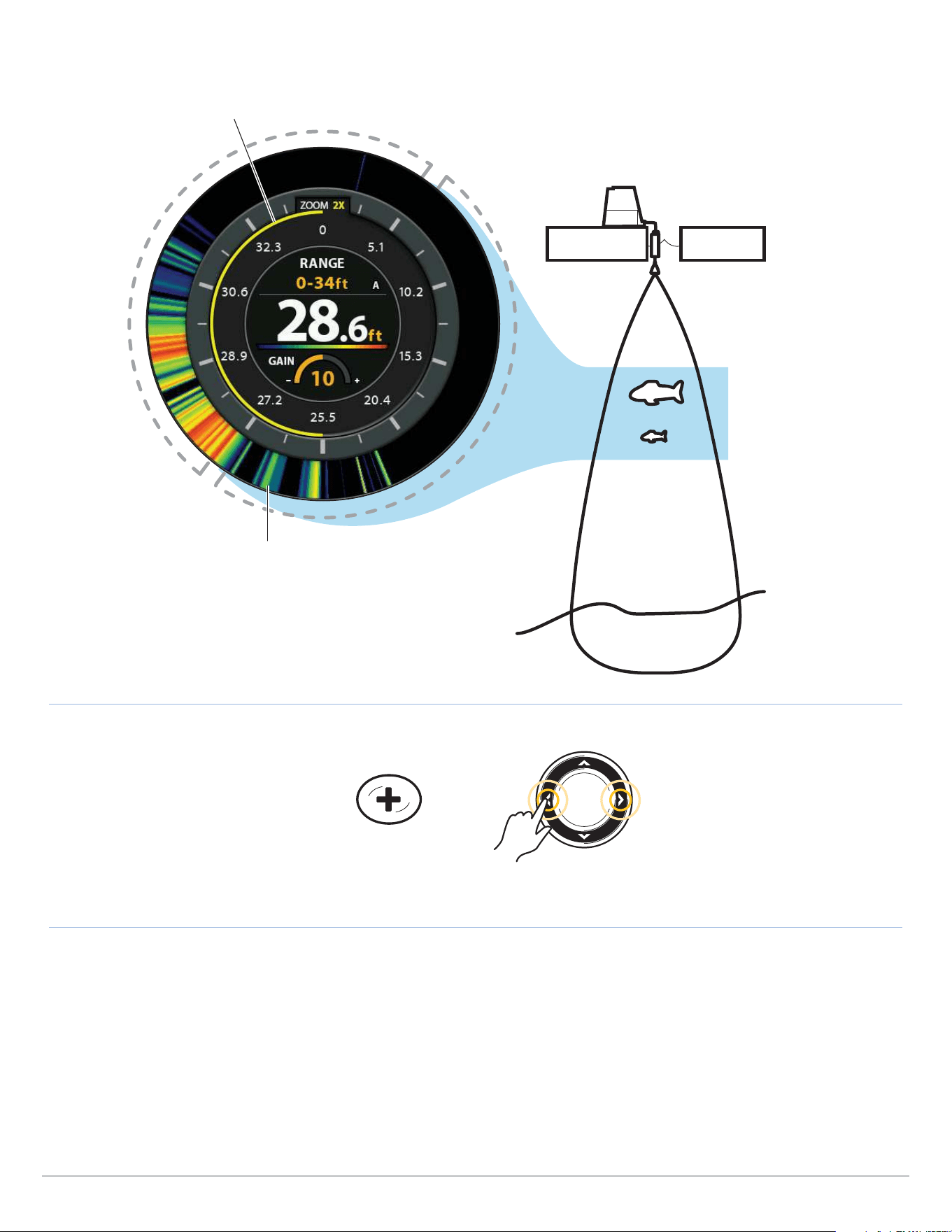
119
Ice Fishing
ZOOM In
(GPS models only)
Move the Zoom Range
Magnifying Sonar Returns in the Flasher View
zoom view
(2X magnification)
zoom range
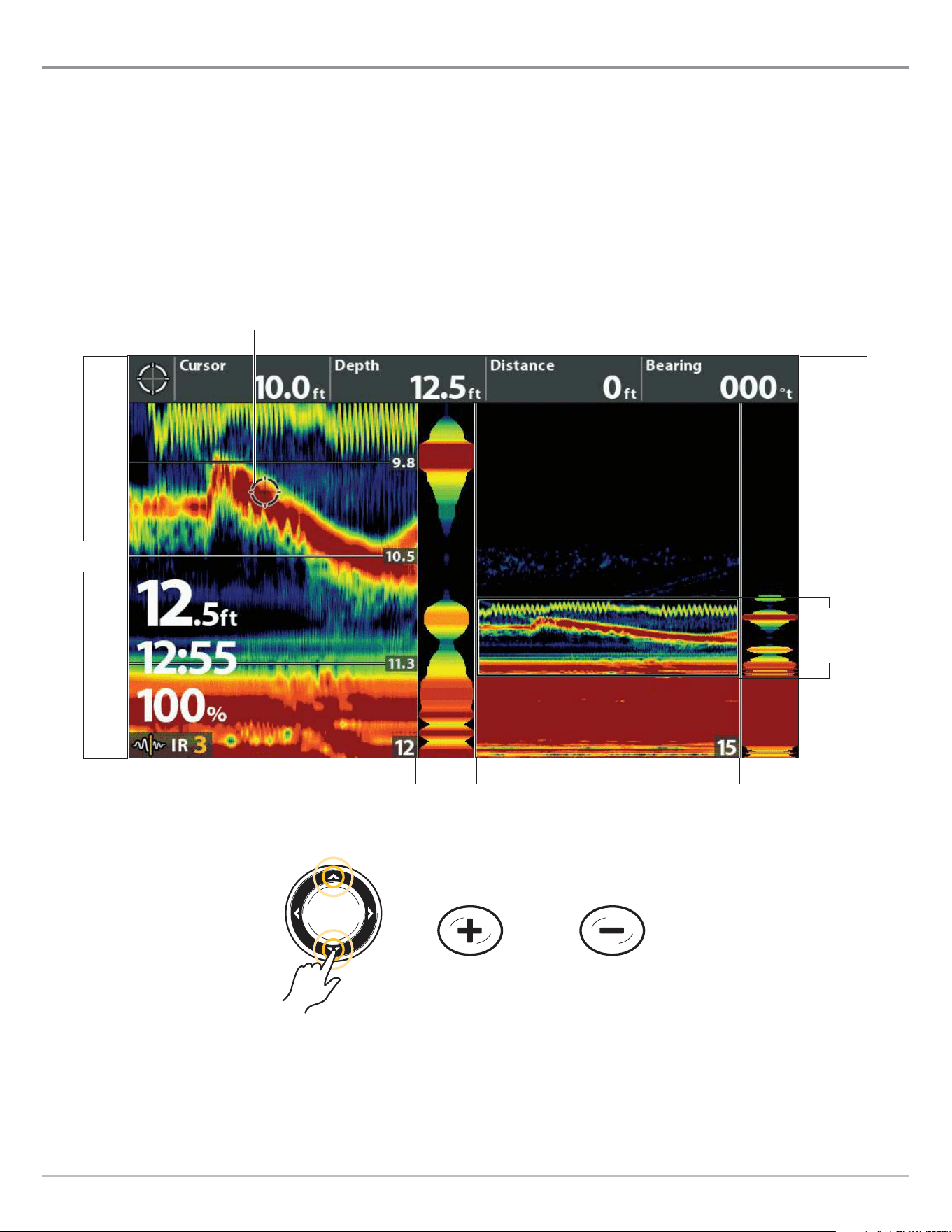
120
Ice Fishing
Using Sonar Zoom View in Ice Fishing mode
Sonar Zoom View provides additional ways to view sonar data for ice fishing. To enable Ice Fishing mode, see Ice Fishing Overview:
Turn on Ice Fishing Mode.
Display the Sonar Zoom View
1. Press and hold the VIEW key.
2. Select Sonar > Sonar Zoom View.
To zoom in and out in Sonar Zoom View using the ZOOM keys or X-Press Menu, see Display a Sonar View On-Screen: Zoom In/
Zoom Out.
ZOOM In
(GPS models only)
Scroll Up and Down
the Water Column
Sonar Zoom View (ICE HELIX 7 CHIRP)
ZOOM Out
(GPS models only)
Active Cursor and Cursor Dialog Box (see Show the Cursor)
RTS window
(narrow)
full range
zoom
preview,
bottom
range
RTS window
(narrow)
zoomed
view
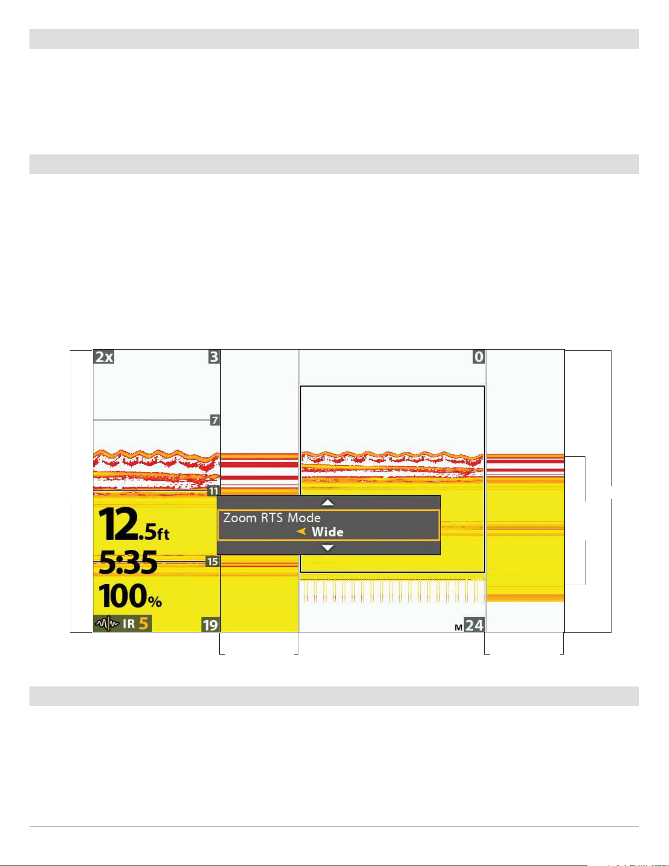
121
Ice Fishing
Show the Cursor
To move the cursor in Sonar Zoom View, you must activate the cursor in the X-Press Menu.
1. Sonar X-Press Menu: With the Sonar Zoom View displayed on-screen, press the MENU key once.
2. Select Show Cursor.
3. Press the RIGHT Cursor key.
Adjust the Zoom RTS Window
The RTS Window plots the depth and intensity of a sonar return. It updates at the fastest rate possible for depth conditions and
shows only the returns from the bottom, structure, and fish that are within the transducer beam. To customize the RTS Window
display, see Customize the Sonar View: Customize the RTS Window.
In Sonar Zoom View, you can adjust the width of the RTS Zoom window. See below.
1. Sonar X-Press Menu: With the Sonar Zoom View displayed on-screen, press the MENU key once.
2. Select Zoom RTS Mode.
3. Press the RIGHT or LEFT Cursor keys to adjust the setting.
Setting the RTS Window Width
zoom
preview,
bottom
range
full range
zoomed
view
RTS window width
(wide)
RTS window width
(wide)
Show/Hide Digital Readouts
Use the Declutter feature to hide digital readouts in a Sonar view when your control head is in Ice Fishing Mode.
1. Sonar X-Press Menu: With a Sonar view displayed on-screen, press the MENU key once.
2. Select Declutter.
3. Press the RIGHT Cursor key.
4. Press Exit.

122
Ice Fishing
Charge Glow-In-The-Dark Lures
Your control head can be used to charge glow-in-the-dark lures.
NOTE: Ice Fishing Mode must be turned on to enable this feature (see Ice Fishing Overview: Turn on Ice Fishing Mode).
Using the Jig Charger
Use the Power X-Press Menu to activate the jig charger. Your screen will display white at full brightness for 10 seconds. Hold the
glow-in-the-dark lure in front of the screen during this time to charge it.
1. Power X-Press Menu: Press the POWER key once.
2. Select Jig Charge.
3. Press the LEFT Cursor key to extend the charging duration by 10 seconds. Press the RIGHT Cursor key to exit the charging
screen early.
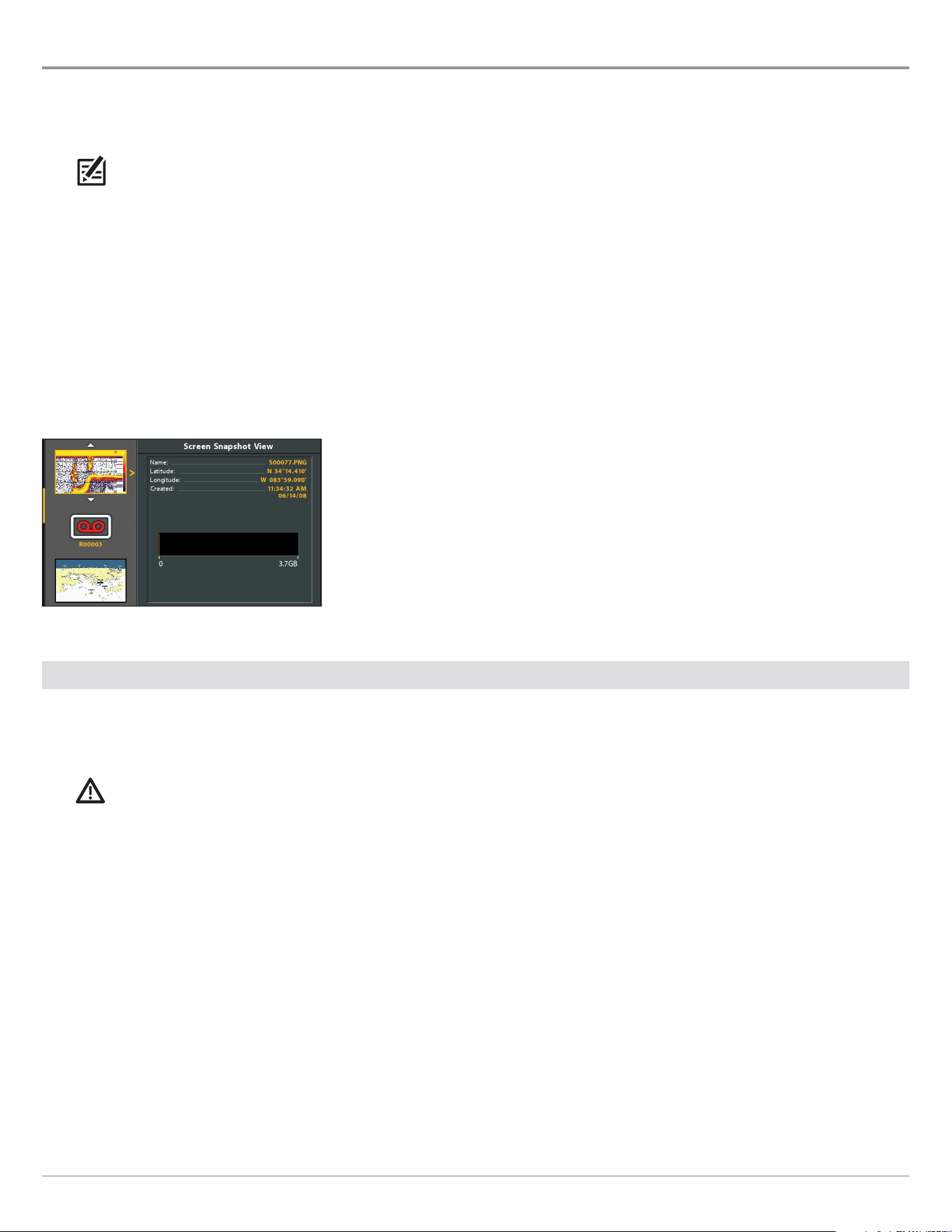
123
Screen Snapshots and Recordings
Manage Screen Snapshots and Recordings
Snapshot and Recording View displays the saved screen snapshots and recordings from the installed microSD or SD card (separate
purchase required). Use this view to review the snapshot and recording file details, start recording, and adjust the recording
settings.
NOTE: Also, this feature can be helpful in troubleshooting any sonar-related issues. If you contact Humminbird Technical Support
for sonar troubleshooting assistance, you may be asked to perform one of the tasks in this section. See Email Files to Technical
Support for details.
Display the Snapshot and Recording View
To view the saved screen snapshots from the installed microSD or SD Card, open the Snapshot and Recording View. If Screen
Snapshot Waypoint is turned on when the screen snapshot is taken, you can view the saved file from Chart View.
1. Press and hold the VIEW key.
2. Select System > Snapshot and Recording View.
Snapshot and Recording View
Enable Screen Snapshot and Recording
To enable Screen Snapshot and Recording, a microSD or SD card must be installed in the control head. See HELIX Control Head for
more information. If Screen Snapshot Waypoint is turned on, a waypoint will also be saved at the boat or cursor location when you
take a screen snapshot. The waypoint is saved with the same file name as the screen snapshot.
CAUTION! On the microSD or SD card, you will see that a DAT (or a .TXT) file is created for every .PNG screen snapshot. This data
file is required for viewing the screen snapshots from your control head, so don’t delete these files.
Enable Screen Snapshot and Recording
1. Install a microSD or SD card into the control head card slot. See HELIX Control Head for compatibility details.
Enable Marking a Waypoint with each Screen Snapshot
If Screen Snapshot Waypoint is turned on, a waypoint will also be saved at the boat or cursor location when you take a screen
snapshot. The waypoint is saved with the same file name as the screen snapshot.
1. Main Menu: Press the MENU key twice. Select the Accessories tab.
2. Select Screen Snapshot Waypoint.
3. Select On.
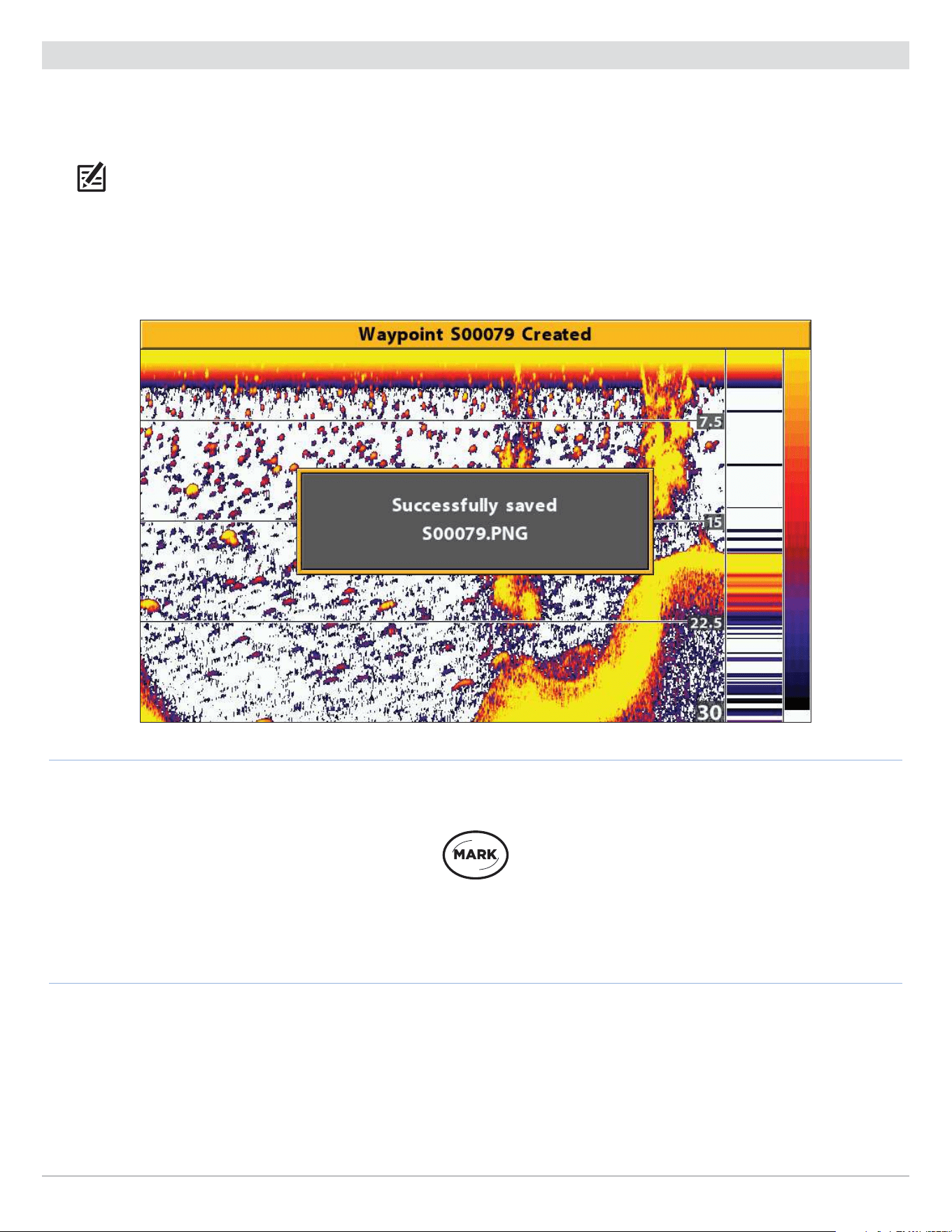
124
Screen Snapshots and Recordings
Take Screen Snapshots
Screen Snapshots are saved pictures of the view on the screen. The screen snapshot will include the menus, dialog boxes, warnings,
and messages that were active when the screen snapshot was taken. If Screen Snapshot Waypoint is turned on, a waypoint will also
be saved at the boat or cursor location when you take a screen snapshot.
NOTE: A microSD or SD card must be installed in the control head to use the Snapshot and Recording features. See HELIX Control
Head for compatibility details.
1. From any view or cursor location you want to capture, press and hold the MARK key.
Taking a Screen Snapshot
Press and Hold to
Take a Screen Snapshot
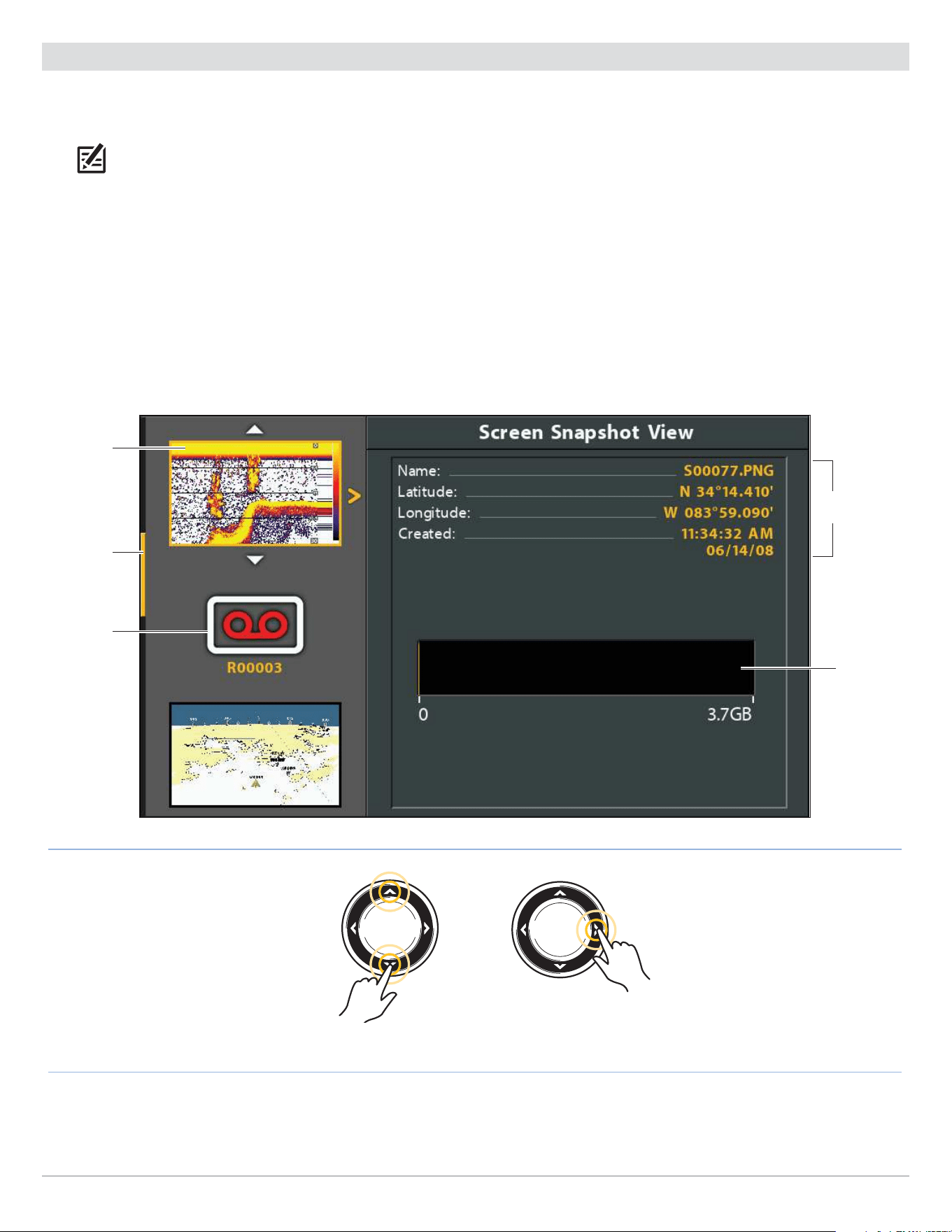
125
Screen Snapshots and Recordings
Manage Saved Screen Snapshots
Saved Screen Snapshots can be viewed from the Snapshot and Recording View. If Screen Snapshot Waypoint is turned on when
the screen snapshot is taken, you can view the saved file from the Chart View.
NOTE: A microSD or SD card must be installed in the control head to use the Snapshot and Recording features. See HELIX Control
Head for compatibility details.
Display a Saved Screen Snapshot from Snapshot and Recording View
1. Display the Snapshot and Recording View on-screen.
2. Select a Snapshot: Press the UP or DOWN Cursor keys to scroll through the saved files.
3. Display: Press the RIGHT Cursor key.
4. Close: Press the LEFT Cursor key.
Snapshot and Recording View
saved
screen
snapshot
(selected
file)
microSD
or SD card
storage
(yellow =
used space)
scroll bar
saved
recording
Scroll through the List Display
selected file
summary
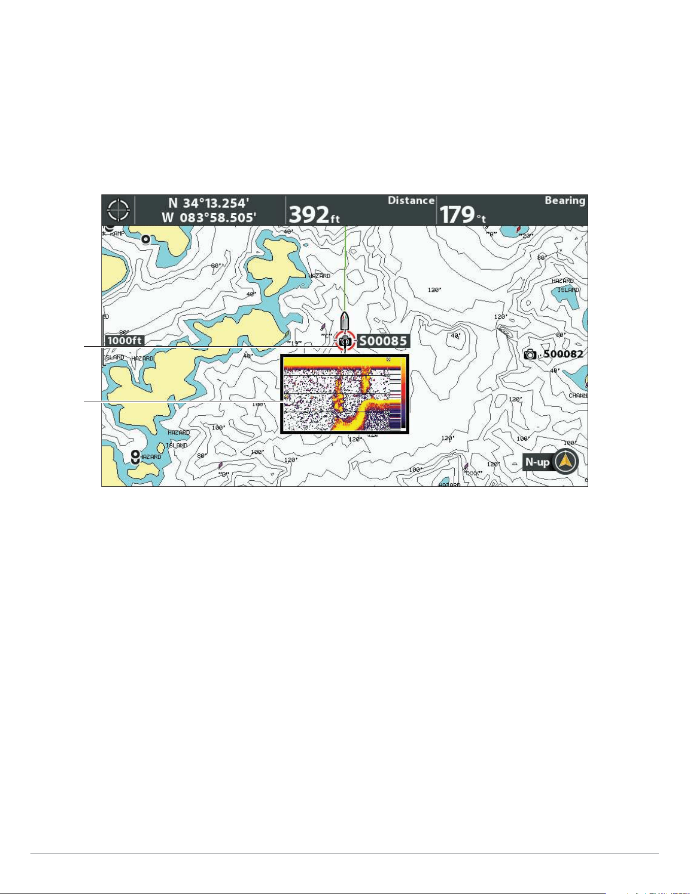
126
Screen Snapshots and Recordings
Display a Saved Screen Snapshot from Chart View
If Screen Snapshot Waypoint is turned on when the screen snapshot is taken, you can view the saved file from the Chart View (see
Enable Marking a Waypoint with each Screen Snapshot).
1. Display a Chart View on-screen.
2. Select a Snapshot: Use the Cursor key to select a screen snapshot icon.
3. Display: Press the CHECK/INFO key.
Selecting a Screen Snapshot in Chart View
(Map Source: Contour XD)
screen
snapshot
icon
selected
thumbnail
preview
4. Close: Press the EXIT key.
Delete a Screen Snapshot
1. Display the Snapshot and Recording View on-screen.
2. Select a Snapshot: Press the UP or DOWN Cursor keys to scroll through the saved files.
3. Press the MENU key.
4. Select Delete Image. Press the RIGHT Cursor key.
Delete all Screen Snapshots
1. Display the Snapshot and Recording View on-screen.
2. Press the MENU key.
3. Select Delete All Images. Press the RIGHT Cursor key.

127
Screen Snapshots and Recordings
Record and Playback
The Recording feature records active sonar information. When the recording is played back, the views that were active during the
recording are available in Playback. You can play a saved recording from the Snapshot and Recording View.
NOTE: A microSD or SD card must be installed in the control head to use the Snapshot and Recording features. See HELIX Control
Head for compatibility details.
Start Recording
1. Display the Snapshot and Recording View on-screen.
2. Press the MENU key.
3. Select Start Recording. Press the RIGHT Cursor key.
File Name: A waypoint will also be created at the boat location, and the recording shares the same file name as the waypoint
(.SON).
Use Different Views: To use different views on the control head and continue recording, press the EXIT key.
Not Available: Taking screen snapshots and playback mode are not available during recording.
Stop Recording
1. X-Press Menu: From any view, press the MENU key once.
2. Select Stop Recording. Press the RIGHT Cursor key.
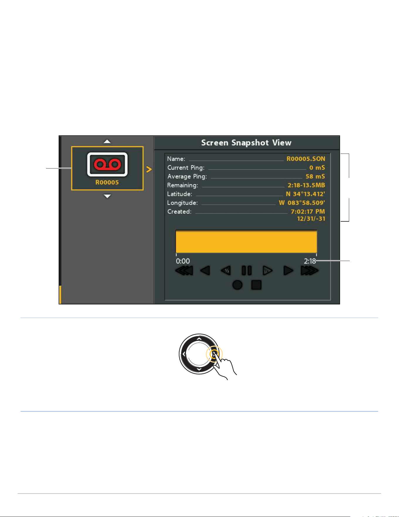
128
Screen Snapshots and Recordings
Play a Recording
1. Display the Snapshot and Recording View on-screen.
2. Select a Recording: Press the UP or DOWN Cursor keys to scroll through the saved files.
3. Start Playback: Press the RIGHT Cursor key.
Navigation is cancelled during playback.
Use Different Views: To use different views on the control head and continue playback, press the EXIT key.
Adjust Sonar: Use the X-Press Menu to adjust sonar settings during playback. You can also use the cursor.
Mark Waypoints: Press the MARK key to mark waypoints during playback.
saved
recording
(selected
file)
Start Playback
Selecting a Recording to Play
selected
recording
size
selected
recording
summary
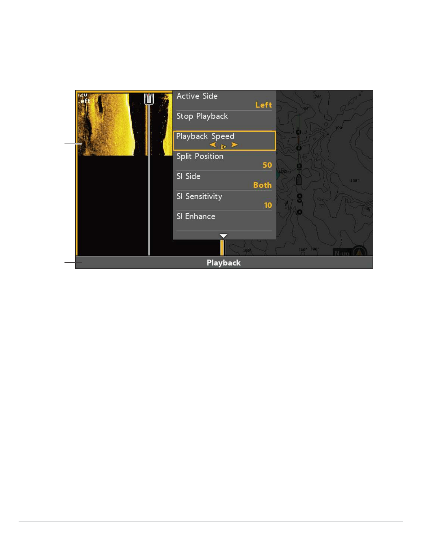
129
Screen Snapshots and Recordings
Adjust Playback Speed
1. X-Press Menu: From any view, press the MENU key once.
2. Select Playback Speed.
3. Press the RIGHT or LEFT keys to adjust playback speed or pause.
Adjusting the Playback Speed
indicates Playback
is in progress
Side Imaging
recording playing
Stop Playback
1. X-Press Menu: From any view, press the MENU key once.
2. Select Stop Playback. Press the RIGHT Cursor key.
Delete a Recording
1. Display the Snapshot and Recording View on-screen.
2. Select a Recording: Press the UP or DOWN Cursor keys to scroll through the saved files.
3. Press the MENU key.
4. Select Delete Recording. Press the RIGHT Cursor key.
Delete all Saved Recordings
1. Display the Snapshot and Recording View on-screen.
2. Press the MENU key.
3. Select Delete All Recordings. Press the RIGHT Cursor key.
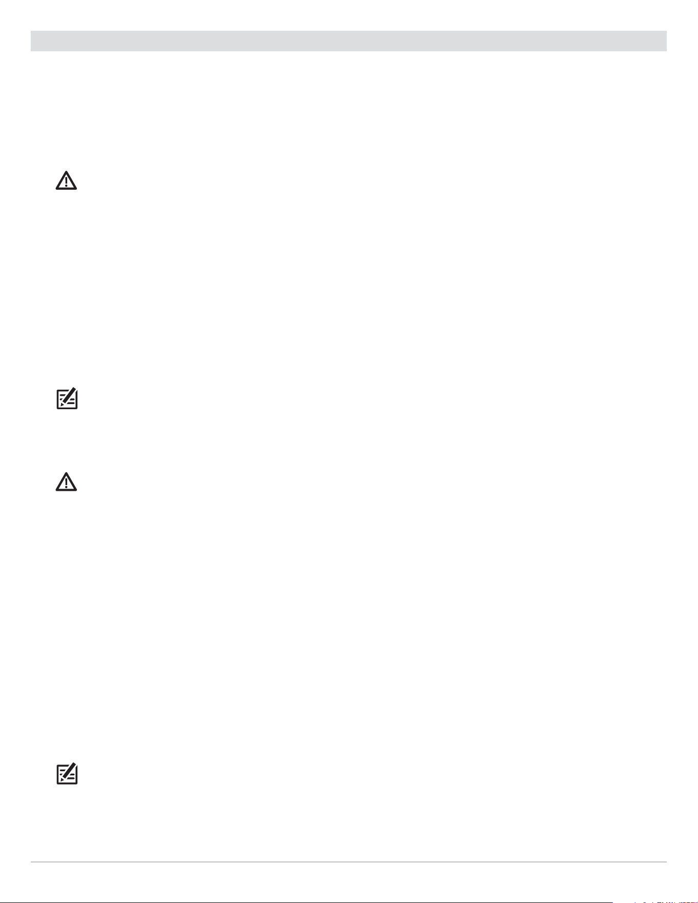
130
Screen Snapshots and Recordings
Email Files to Technical Support
If you’re working with Humminbird Technical Support to troubleshoot a sonar-related issue, they may ask you to send a screen
snapshot or recording to them for review. Use the instructions in this section to email a saved screen snapshot or recording to
Humminbird Technical Support. For more information, see humminbird.com.
Email a Saved Screen Snapshot
1. Install the SD or microSD card (and adapter) with the saved screen snapshots and recordings into your personal computer.
CAUTION! On the microSD or SD card, you will see that a DAT (or a .TXT) file is created for every .PNG screen snapshot. This data
file is required for viewing the screen snapshots from your control head, so don’t delete these files. See HELIX Control Head for
compatibility details.
2. Open your email account and compose a new message.
If Technical Support has provided a customer number, include it in the subject line.
3. Attach the screen snapshot files to the message. For each screen snapshot, attach the Sxxxxx.PNG file.
Folder: Screen Snapshots are saved in the SNAPSHOT folder on the microSD or SD card.
File Names: The .PNG file and .DAT file for each screen snapshot have the same name. Unless you have edited the name,
screen snapshots start with S.
4. Repeat step 3 for each screen snapshot.
5. Send the email to Humminbird Technical Support.
NOTE: If the attached files are large, you may need to use win-zip or a similar program to compress the files and send them via email.
Email a Saved Recording
1. Install the microSD or SD card adapter with the saved screen snapshots and recordings into your personal computer.
CAUTION! On the microSD or SD card, you will see that a DAT (or a .TXT) file is created for every recording folder. This data file is
required for viewing the recordings on your control head, so don’t delete these files. See HELIX Control Head for compatibility
details.
2. Open your email account and compose a new message.
If Technical Support has provided a service number, include it in the subject line.
3. Attach the Rxxxxx.DAT file for the recording to the message.
Folder: Recordings are saved in the RECORD folder on the microSD or SD card.
4. Attach all the files in the Rxxxxx folder to the message. Open the RECORD folder, and open the folder with the Recording
name.
Folder: Recordings are saved in the RECORD folder on the microSD or SD card. Unless you have edited the name, recordings
start with R. Open the Rxxxxx folder for the recording. For example, to send the files for the R00001 recording, open the
R00001 folder.
File Names: Attach all the .SON files and .IDX files in the recording folder.
5. Repeat step 3 and 4 for each recording.
6. Send the email to Humminbird Technical Support.
NOTE: If the attached files are large, you may need to use win-zip or a similar program to compress the files and send them via email.
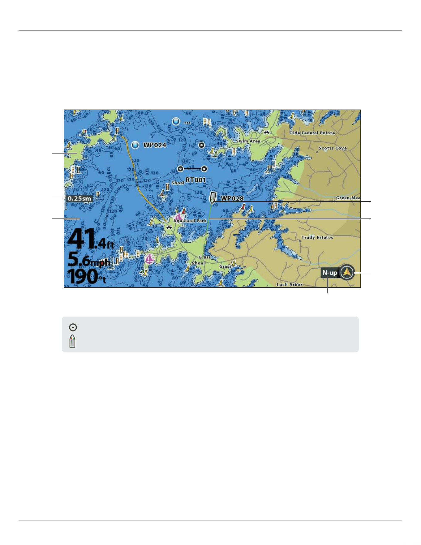
131
Chart Overview
Chart Overview
To enable the chart and navigation features, the control head must have a GPS Fix from an internal or external GPS receiver (see
Getting Started to check the sensor reception). Some of these features also require a compass/heading sensor to be connected
to the control head.
The selected map source also influences the menu system. When you change the map source, the menu options for the chart views
change, allowing you to add navigation data, shading, or alarms. See Select a Map Source for details.
Chart View with Built-in Humminbird Basemap (HELIX 9 CHIRP MDI GPS)
map scale
course
projection
line
boat icon
land
water
chart
orientation
north up
indicator
When the boat is stationary, it is drawn as a circle.
When the boat is in motion, it changes to a boat shape, pointed in the direction of motion.
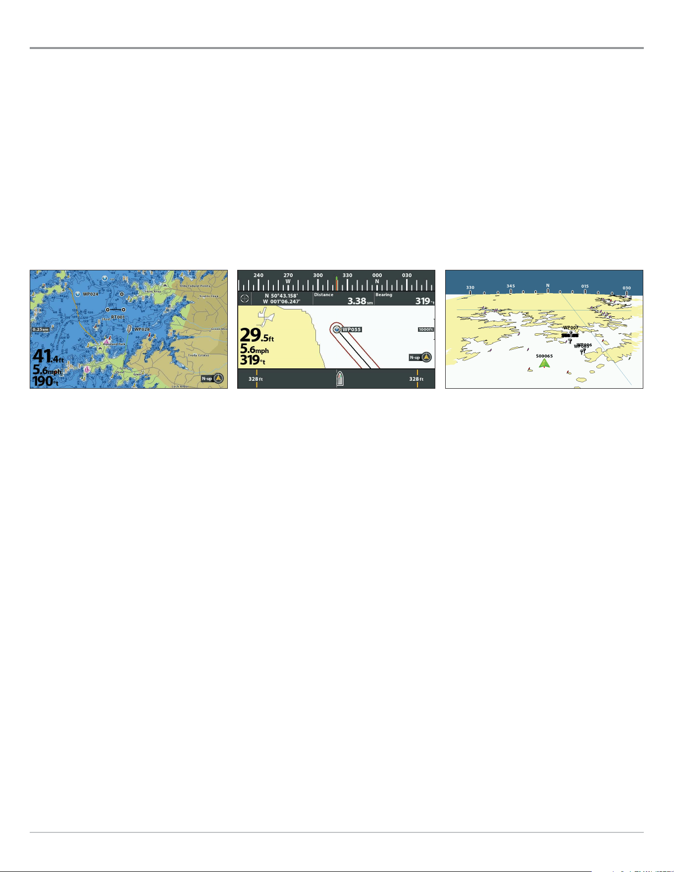
132
Chart Overview
Display a Chart View On-Screen
There are a variety of views available to display charts and navigation. The views can be customized and displayed as a Combo View.
Display a Chart View or Bird’s Eye View
Bird’s Eye View is only available when Contour XD or a Navionics map card is selected as the map source.
1. Press and hold the VIEW key.
2. Select Chart > Chart View or Chart Instrument View.
OR
Select Chart > Bird’s Eye View.
Bird’s Eye View
(with Contour XD or Navionics only)
For more information, see
Customize the Bird’s Eye View.
Chart Instrument View
(Map Source: Contour XD)
For more information, see
Customize the Chart Instrument View.
Chart View
(Map Source: Humminbird Basemap)
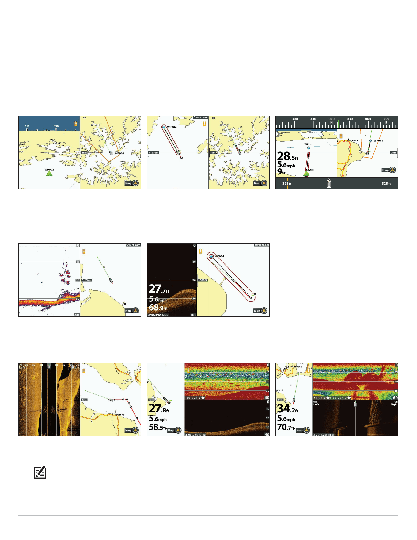
133
Chart Overview
Display a Chart Combo View
You can select a variety of Chart Combo Views or Chart/Sonar Combo Views.
1. Press and hold the VIEW key.
2. Select Chart.
3. Select a view to display on-screen. Press the RIGHT Cursor key.
Chart > Chart/BE Instrument View
(with Contour XD or Navionics only)
For more information, see
Customize the Chart Instrument View and
Customize the Bird’s Eye View.
Chart > Chart/Chart Combo View
(Map Source: Contour XD)
Chart > Chart/Bird’s Eye Combo View
(with Contour XD or Navionics only)
For more information, see
Customize the Bird’s Eye View.
For more information, see the
Down Imaging section.
Chart > Chart/Down Combo View
(Map Source: Contour XD)
For more information, see the
Sonar section.
Chart > Chart/Sonar Combo View
(Map Source: Contour XD)
Chart > Chart/Sonar/Side Combo View
(Map Source: Contour XD)
For more information, see the
Sonar and Side Imaging sections.
For more information, see the
Sonar and Down Imaging sections.
Chart > Chart/Sonar/Down Combo View
(Map Source: Contour XD)
For more information, see the
Side Imaging section.
Chart > Chart/Side Combo View
(Map Source: Contour XD)
NOTE: The available views are determined by your control head model and the installed transducer. For a complete list of the
views available on your control head, press the MENU key twice, and select the Views tab. See each related section of the manual
(Views, Sonar, Side Imaging, Navigation Overview, etc.) for more information.
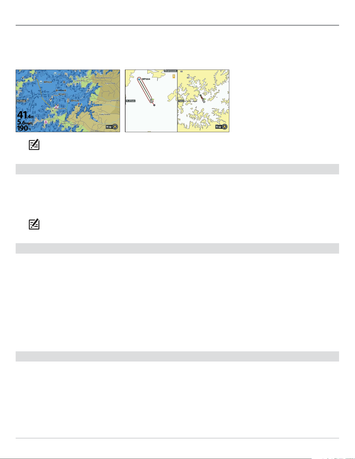
134
Chart Overview
Select a Map Source
The HELIX control head includes built-in maps, including the Humminbird Basemap and Contour XD. You can also install a microSD
or SD map card with additional chart information for a particular location (separate purchase required). See HELIX Control Head
for compatibility details.
Chart/Chart Combo View
(Map Source: Contour XD)
Chart View
(Map Source: Humminbird Basemap)
NOTE: Your control head may require a software update to display the Humminbird Basemap. See Update Software and visit our
Web site at humminbird.com for more information.
Install a microSD or SD Map/Chart Card
When you install a microSD or SD map or chart card, the control head automatically chooses the best map to display. You can also
change the map source manually. If your control head has two cards installed, you can choose which map source you want to use
(HELIX 8, 9, 10, 12 only).
1. Install a microSD or SD map/chart card into the control head card slot. See HELIX Control Head for compatibility details.
NOTE: Do not leave the card slot cover open. The slot cover should always be closed to prevent water damage to the unit.
Change the Map Source
When you install a microSD or SD map/chart card, the map source is changed automatically to match the microSD or SD map/
chart card map source. You can also change the map source manually.
When you change the map source, the available views and menus for the chart views also change, allowing you to add navigation
data, shading, alarms, and more.
1. Main Menu: Press the MENU key twice. Select the Chart tab.
2. Select Map Source.
3. Select the installed map/chart card location or a built-in map.
Auto: The best available map will be selected automatically.
Change Map Options
Change the Map Coordinate System (optional, Contour XD and Navionics map cards only)
Use Map Datum to change the map coordinate system used by the control head to match those of a paper map. Almost all
electronic charts use the WGS84 Map Datum and most likely do not require a setting change. (Default = WGS84)
1. Main Menu (Custom User Mode): Press the MENU key twice. Select the Chart tab.
2. Select Map Datum.
3. Press the RIGHT or LEFT Cursor keys to change the setting.

135
Chart Overview
Apply an Offset to the Map (optional, Contour XD and Navionics map cards only)
Use Set Map Offset to move the chart position on-screen and correct a position error in the cartography. This setting applies to all
charts, not just the chart that requires correction.
NOTE: This feature is not available with Humminbird LakeMaster map cards or CoastMaster chart cards.
1. Display a Chart View on-screen.
2. Use the Cursor Control key to move the cursor to the position where the map offset will be applied.
3. Main Menu (Custom User Mode): Press the MENU key twice. Select the Chart tab.
4. Select Set Map Offset.
5. Press the RIGHT Cursor key.
6. Follow the on-screen prompts.
Clear Map Offset: Select Main Menu (Advanced User Mode) > Chart tab > Clear Map Offset.
Select a New Map (optional, Contour XD and Navionics map cards only)
If the installed map card includes additional maps, use the following instructions to display map borders and select a different map.
1. Main Menu: Press the MENU key twice. Select the Chart tab.
2. Select Map Borders.
3. Select MMC/SD Only or All Visible.
4. Display a Chart View on-screen.
5. Use the Cursor Control key to move the cursor within the dotted lines of a map border.
6. Press the +ZOOM key repeatedly to display the map details.
See Customize the Chart View: Customize the Chart Detail Level.
Change the Simulation Position (optional)
Simulator mode allows you to save menu settings and navigation data while you learn to use your control head. To start simulation
mode, see Getting Started. To change the simulation position shown on the Chart View, use the following instructions.
Simulation mode is not intended for on the water use. If you are on the water, use Normal mode. See Getting Started for details.
1. Display a Chart View on-screen.
2. Use the Cursor Control key to move the cursor to a position on the view.
3. Main Menu (Custom User Mode): Press the MENU key twice. Select the Chart tab.
4. Select Set Simulation Position.
5. Press the RIGHT Cursor key.
The boat icon will move to the new position.
Clear the Track: Press the MENU key once. Select Clear Current Track.

136
Chart Overview
Set up Humminbird ChartSelect
ChartSelect allows you to purchase a Humminbird chart online and download it to a blank microSD or SD Card. Visit chartselect.
humminbird.com for more information and to download the ChartSelect and FishSmart User Guide.
To display purchased ChartSelect charts and/or overlays, see Display Chart Overlays.
Encrypt a microSD or SD Card
Use the Encrypt SD Card menu to prepare a blank microSD or SD card for ChartSelect. See HELIX Control Head for compatibility
details.
WARNING! Do not use this menu with a microSD or SD map card installed. You must use a blank microSD or SD card with this
menu. See the ChartSelect and FishSmart User Guide before proceeding.
1. Main Menu: Press the MENU key twice. Select the Setup tab.
2. Select Encrypt SD Card.
3. Press the RIGHT Cursor key.
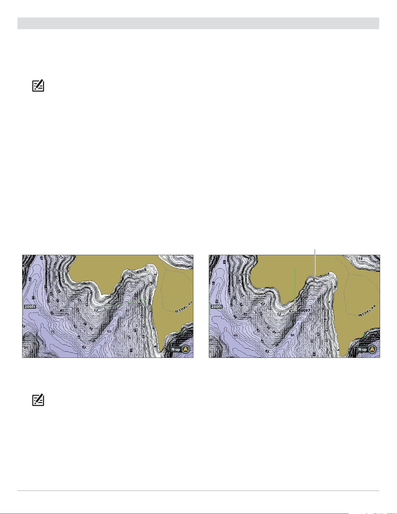
137
Chart Overview
Set up Humminbird LakeMaster
When a Humminbird LakeMaster map card is installed and selected as the map source, additional menus are added to the menu
system. The menu options are determined by the map card you purchased.
Compatible Map Sources: Humminbird LakeMaster, LakeMaster PLUS, ZeroLine Map Card, AUTOCHART PC, etc. Visit our Web site
at humminbird.com for compatibility details and updates.
NOTE: A Humminbird LakeMaster map card must be installed and selected as the map source to enable this feature (see Change
the Map Source).
To display purchased ChartSelect charts and/or overlays, see Display Chart Overlays.
Set the Water Level Offset
When you start your trip for the day, it is important to note if the water level is higher or lower than normal. For example, if you know
the lake is down 3 feet, set the Water Level Offset to -3.
1. Main Menu: Press the MENU key twice. Select the HB Chart tab.
2. Select Water Level Offset.
3. Press the RIGHT or LEFT Cursor keys to adjust the setting.
If the water level is higher than normal, set a (+) positive amount.
If the water level is lower than normal, set a (-) negative amount.
If the water level has not changed (normal), set Water Level Offset to (0) zero.
Water Level Offset (Set to 0 = Off) Water Level Offset Adjusted to -4
If the water is lower than normal, set the Water Level Oset to a negative
number, and the land will extend visually on the map (as shown above). If the
water is higher than normal, set the Water Level Oset to a (+) positive amount,
and the water line will extend visually on the map.
NOTE: For additional LakeMaster map card menus, see Display Humminbird LakeMaster Contour Lines and Depth Ranges in
this manual. For additional features related to your LakeMaster map card, visit our Web site at humminbird.com to download the
accessory guide.
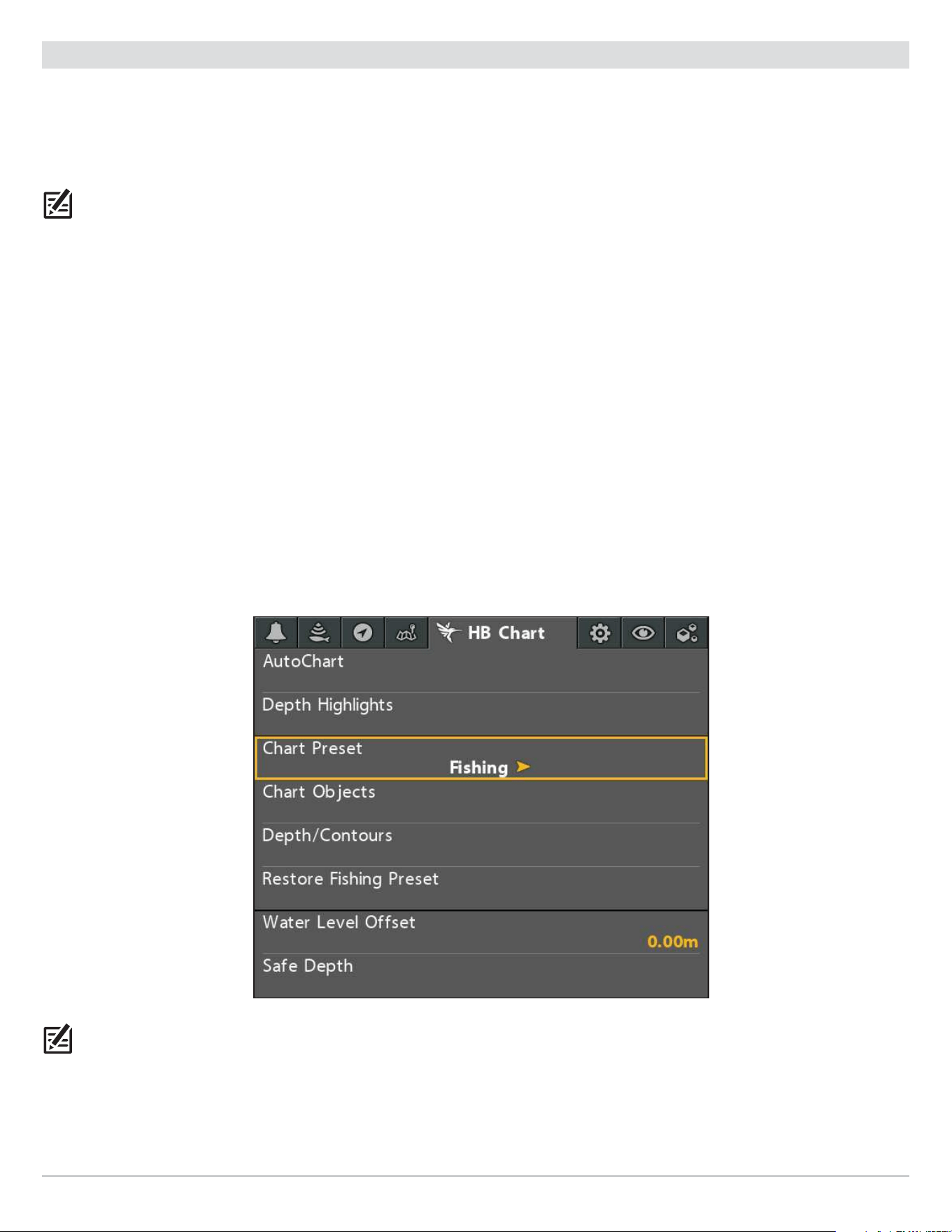
138
Chart Overview
Set up Humminbird CoastMaster
When a Humminbird CoastMaster chart card is installed and selected as the map source, additional menus are added to the menu
system.
Compatibility: Humminbird CoastMaster chart cards are available to use with HELIX G3, G3N and G4N control heads with
chartplotting capabilities. Visit humminbird.com to review the latest compatibility information.
NOTE: A Humminbird CoastMaster chart card must be installed and selected as the map source to enable this feature (see Change
the Map Source).
Automatic Display: The map displayed on the Chart View is based on your latitude/longitude position and the chart card installed
in the control head, so your current position will be displayed automatically. GPS reception is required for the correct position to
be displayed.
If your current position is not displayed, confirm you have GPS reception and that your CoastMaster Chart Card is installed. Also,
review the Map Source:
Select a Chart Preset
Use Chart Presets to quickly alternate between settings. You can use the default Fishing or Navigation settings provided, or you
can create a custom User preset with your preferences. The Fishing and Navigation presets are also fully customizable. You can
restore each preset back to its default settings at any time.
1. Main Menu: Press the MENU key twice. Select the HB Chart tab.
2. Select Chart Preset.
3. Press the RIGHT or LEFT Cursor keys to select your Chart Preset.
Select a Chart Preset
NOTE: For additional CoastMaster chart card menus, see Display Humminbird CoastMaster Contour Lines and Depth Ranges in
this manual. For additional features related to your CoastMaster chart card, visit our Web site at humminbird.com to download the
CoastMaster User Manual.
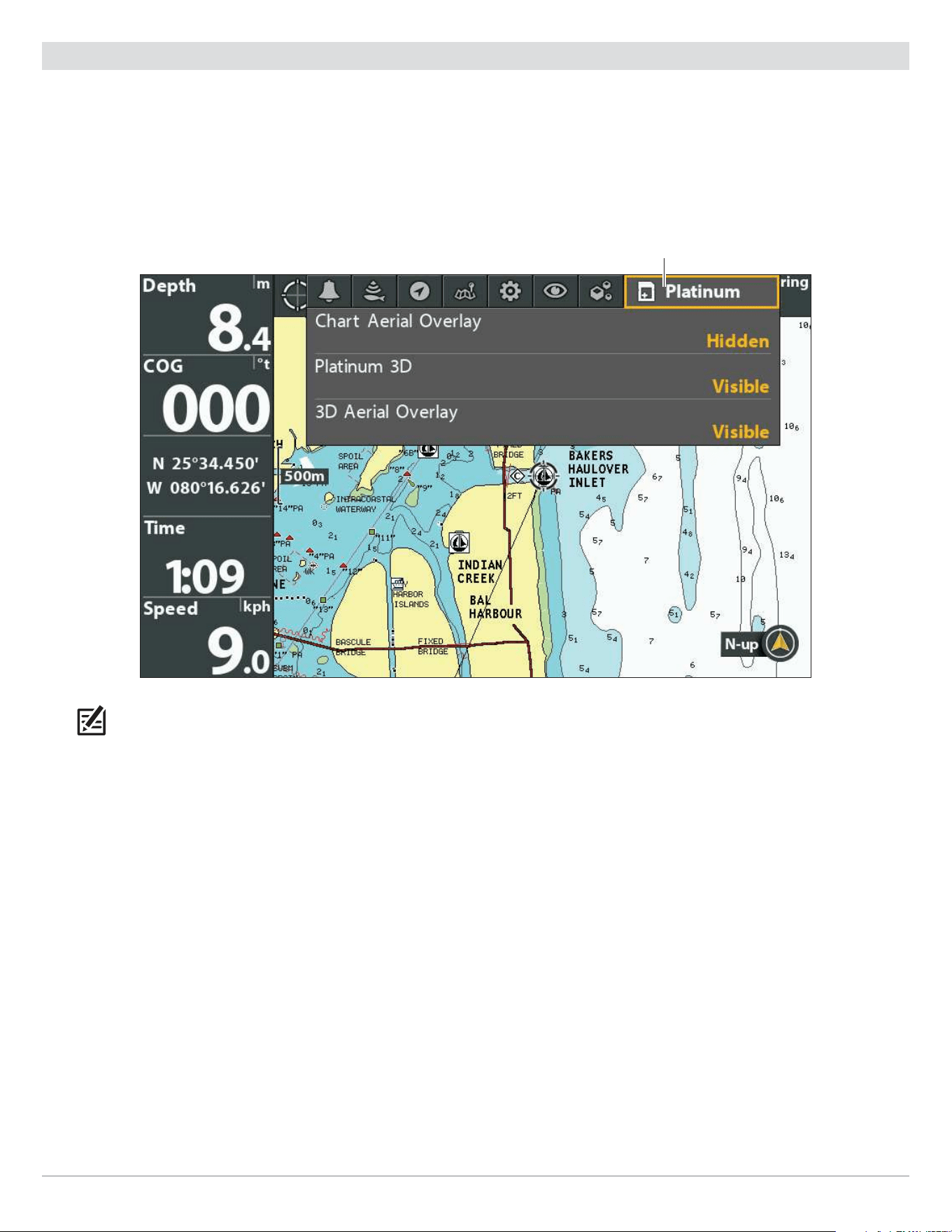
139
Chart Overview
Set up Navionics
When a Navionics map card is installed and selected as the map source, additional menus are added to the menu system. The
menu options are determined by the map card you purchased, and they are available in the Chart tab (see Customize the Chart
View) and/or the Platinum tab.
Compatible Map Sources: Navionics+, Navionics Gold, HotMaps, HotMaps Premium, and Platinum+. Visit our Web site at humminbird.
com for compatibility details and updates.
Selecting the Navionics Platinum Tab
Platinum tab
NOTE: A Navionics map card must be installed and selected as the map source to enable these features (see Change the Map
Source). For details and additional features related to your Navionics map card, see your Navionics map card user guide.
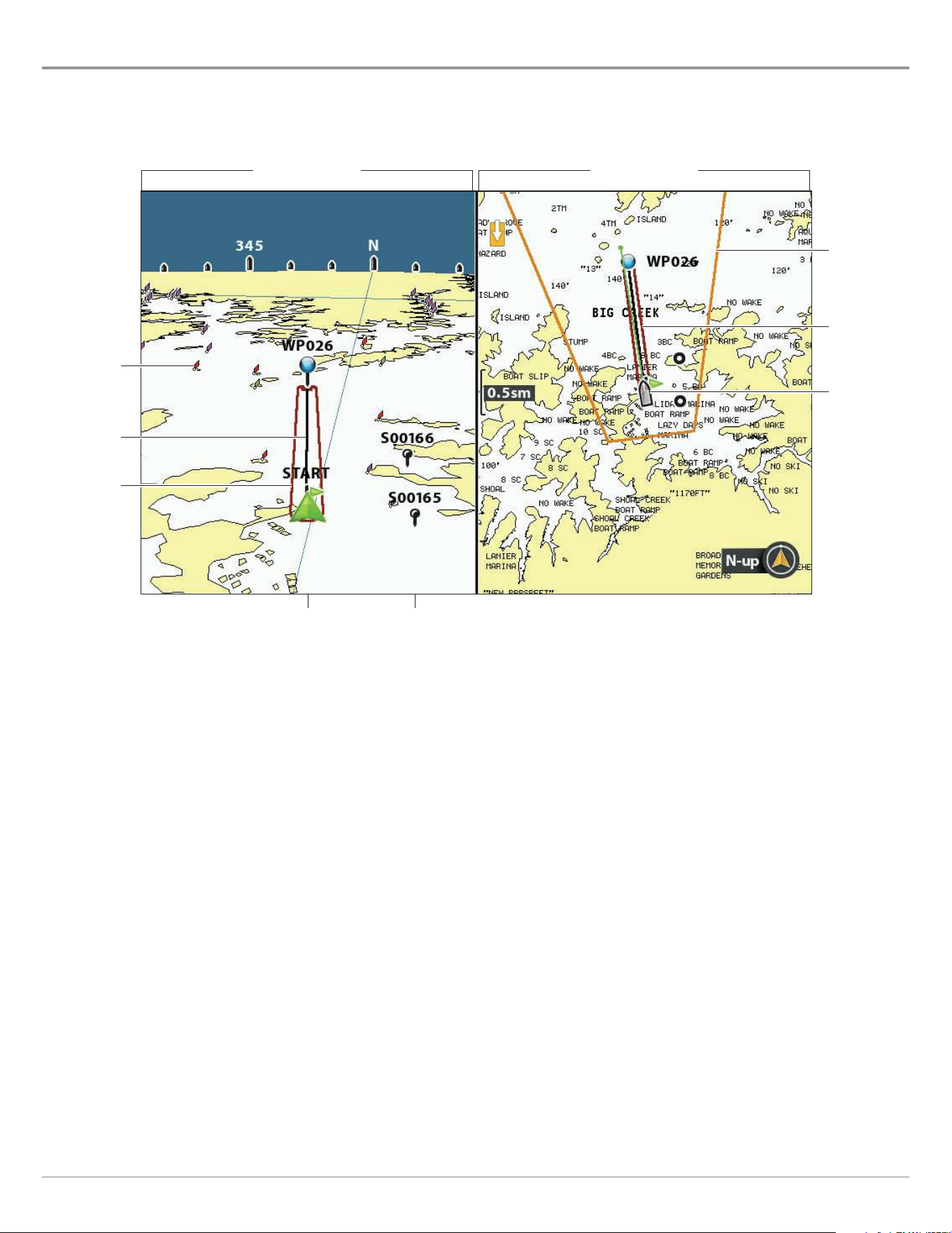
140
Customize the Chart Instrument View
Customize the Bird’s Eye View
(Contour XD and Navionics only)
Navaids on Bird’s Eye View allows you to add navigational aids to the Bird’s Eye View, such as lights or buoys. The available settings
are determined by the installed map card and the selected map source.
waypointboat icon
Chart View
Chart/Bird’s Eye Combo View
3D view
outline set
to visible
Bird’s Eye View
navaids set
to visible
route
o course
limits
o course
limits
boat icon
Show/Hide Navaids
1. Main Menu: Press the MENU key twice. Select the Chart tab.
2. Select Navaids on Bird’s Eye View.
3. Select Visible or Hidden.
Show/Hide the Bird’s Eye Outline
If you use the Chart/Bird’s Eye View, you can display a line on the Chart View that shows the portion of the view that is used in the
Bird’s Eye View.
1. Main Menu: Press the MENU key twice. Select the Nav tab.
2. Select 3D View Outline.
3. Select Visible or Hidden.
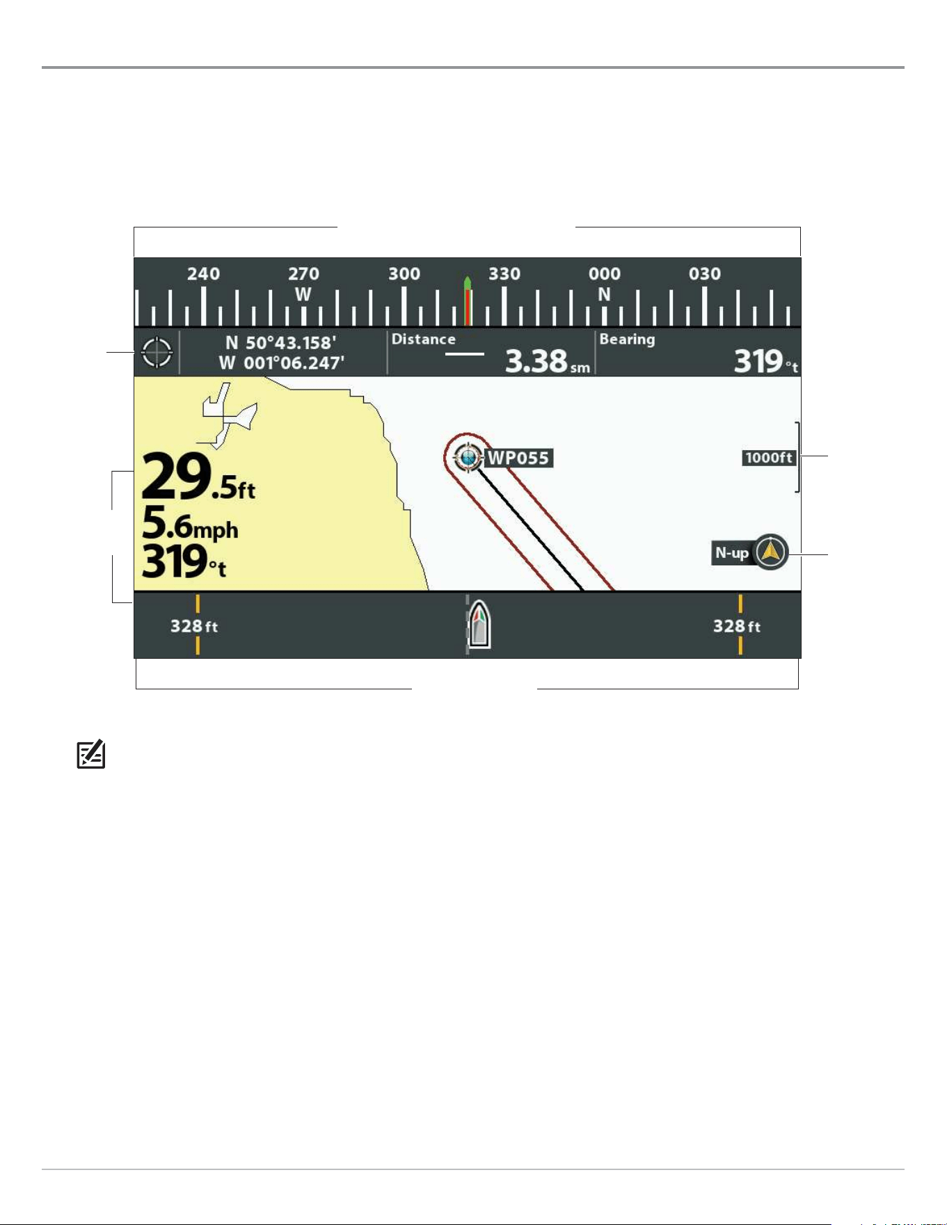
141
Customize the Chart Instrument View
Customize the Chart Instrument View
The Chart Instrument View displays a digital compass and XTE (Cross Track Error) graphic on the Chart View. If a compass is not
installed, the COG (Course Over Ground) provides the data source for the digital compass.
The Chart Instrument View shares the same menu settings as the Chart View. For customization information, see Customize the
Chart View.
Chart Instrument View
north up
indicator
map scale
cursor
digital
readouts
digital
readouts set
to overlay
XTE (cross track error)
digital compass (COG or connected compass)
NOTE: Digital readouts can be displayed as an overlay, or they can be displayed in data boxes (see Views: Display Digital
Readouts).
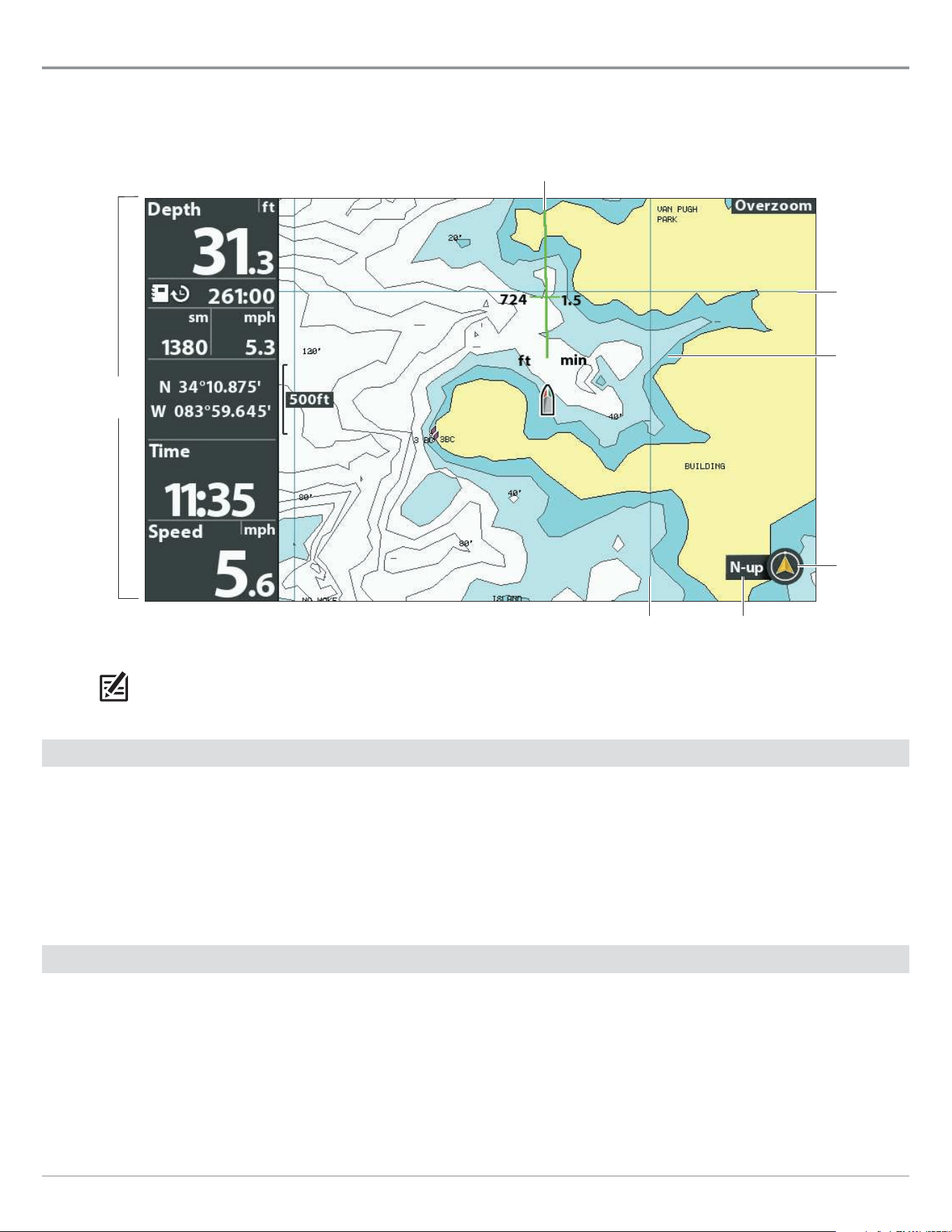
142
Customize the Chart View
Customize the Chart View
The settings in this section are optional. You can use the default settings for the chart appearance and map source, or you can
customize the Chart View.
Customizing the Chart View (Map Source: Contour XD)
course projection line set to COG/SOG
digital
readouts set
to boxes
north up
indicator
chart
orientation
longitude line
latitude
line
shaded
depth
NOTE: Digital readouts can be displayed as an overlay, or they can be displayed in data boxes (see Views: Display Digital
Readouts).
Change the Background Color
The Background menu changes the color of the background on the view. This menu also changes the background color for the
Bird’s Eye View.
1. Press the POWER key.
2. Select Background.
3. Select a color.
Show/Hide the North Up Indicator Icon
The North Up Indicator displays the direction of True North. The icon also displays the chart orientation, and it will change as the
orientation and the data source change. To set the Chart Orientation, see Change the Chart Orientation and Motion Mode.
1. Main Menu: Press the MENU key twice. Select the Chart tab.
2. Select North Up Indicator.
3. Select Off (hidden) or On (visible).

143
Customize the Chart View
Show/Hide the Course Projection Line
The course projection line is an arrow or line extending from the bow of the boat icon. It projects the current course and shows
where the boat will go if you continue on your present course.
1. Main Menu: Press the MENU key twice. Select the Nav tab.
2. Select Course Projection Line.
3. Select a display setting.
Hidden The Course Projection line will not be displayed.
Standard arrow
Single Vector line
COG/SOG
A line with tick marks will be displayed at set intervals from the boat. The tick marks are based
on the speed calculation.
Show/Hide Latitude/Longitude Lines
Use the following instructions to show or hide latitude and longitude lines on the Chart View.
1. Main Menu: Press the MENU key twice. Select the Chart tab.
2. Select Lat/Lon Grid.
3. Select Visible or Hidden.
Adjust the Depth Shading
Shaded Depth allows you to change the depth used for shading on the Chart View. The available settings are determined by the
installed map card and selected map source.
1. Main Menu: Press the MENU key twice. Select the Chart tab.
2. Select Shaded Depth.
3. Press the RIGHT or LEFT Cursor keys to adjust the setting.
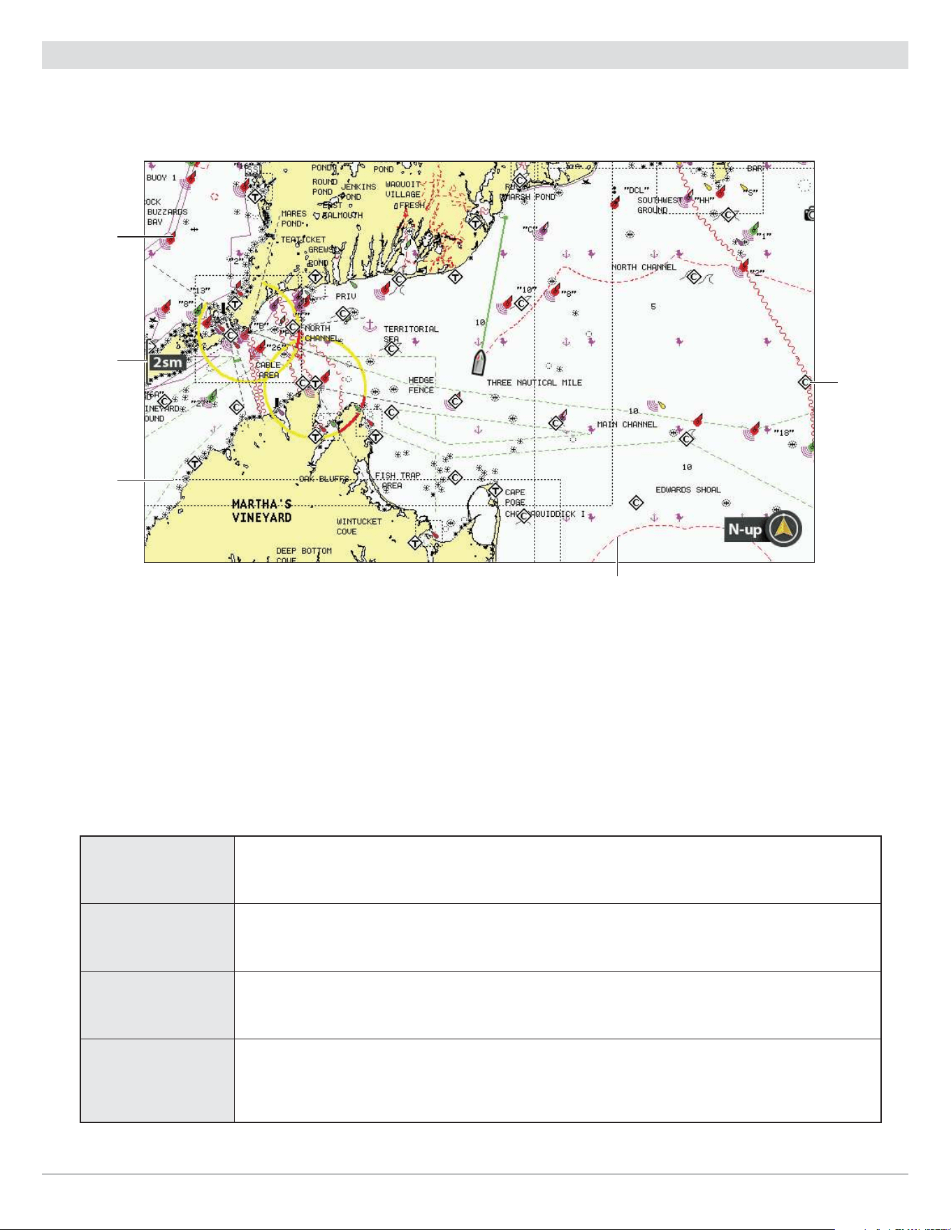
144
Customize the Chart View
Customize the Chart Detail Level
Use the following instructions to add or hide chart details and navaids on the Chart View and the Bird’s Eye View.
map scale
navaid
map border
(dotted
black line)
restricted area
(dashed red lines)
Navionics Chart Displayed with Chart Detail set to Navigation
chart info
Select a Chart Detail Level
Chart Detail Level allows you to add details and layers to the chart views. The available settings are determined by the installed
map card and selected map source.
1. Main Menu: Press the MENU key twice. Select the Chart tab.
2. Select Chart Detail Level.
3. Press the RIGHT or LEFT Cursor keys to select one of the following:
Basic
shows land areas, ports, obstructions, and restricted areas
Navigation
In addition to the Basic level, Navigation shows navaids, landmarks, ferryways, and navigation
routes.
Underwater
In addition to the Basic and Navigation information, Underwater shows depth contours, fishing
areas, underwater wrecks, tides, and currents.
Custom
(Custom User
Mode)
Select Custom to select specific chart detail layers. You can show or hide chart layers such
as navigation canals, boundaries, restricted areas, coastline, bridges, and more. See Select
Custom Chart Layers.

145
Customize the Chart View
Select Custom Chart Layers
1. Main Menu (Custom User Mode): Press the MENU key twice. Select the Chart tab.
2. Select Chart Detail Level.
3. Select Custom.
4. Press the DOWN Cursor key.
5. Select Custom Chart Layers. Press the RIGHT Cursor key.
6. Use the Cursor key to select a layer and turn it on (visible) or off (hidden).
Simplify the Chart Detail Level
Use Chart Declutter to remove all chart layers except for land outlines, waypoints, routes, and tracks. The chart will
clear
for 10
seconds, and then it will refresh to its previous display settings.
1. Chart X-Press Menu: With a Chart View displayed on-screen, press the MENU key once.
2. Select Chart Declutter.
3. Press the RIGHT Cursor key.
Show/Hide Map Borders
The dotted lines of a map border indicate an area that contains a different map. See Select a Map Source: Select a New Map for
details. The available settings are determined by the installed map card and selected map source.
1. Main Menu: Press the MENU key twice. Select the Chart tab.
2. Select Map Borders.
3. Select Hidden, MMC/SD only, or All Visible.
Show/Hide Spot Soundings
Spot Soundings are depth measurements shown on the chart. The available settings are determined by the installed map card
and selected map source.
1. Main Menu: Press the MENU key twice. Select the Chart tab.
2. Select Spot Soundings.
3. Select Visible or Hidden.
Increase the Text Size
Turn on Easy View Text to increase the size of the text displayed on the chart view. The available settings are determined by the
installed map card and selected map source.
1. Main Menu: Press the MENU key twice. Select the Chart tab.
2. Select Easy View Text.
3. Select On or Off.

146
Customize the Chart View
Display Chart Overlays
(LakeMaster PLUS map card and ChartSelect maps only)
If you purchased a Humminbird LakeMaster PLUS map card or ChartSelect lake maps (that are saved to an ecrypted SD card), you
can select a base layer and add overlays to the Chart View to add more detail to your map.
The available settings are determined by the installed map card and selected map source. The LakeMaster map card or SD card
with ChartSelect chart layers must be selected as the map source. See Select a Map Source: Select a New Map for details.
NOTE: Overlays cannot be used when Humminbird Basemap or ContourXD is selected as the map source.
Display/Hide a Base Layer
Use the following instructions to change the Base Layer for the Chart View. The selected Base Layer will also be applied to the left
window of the Chart/Chart Combo View and the Chart window in Chart Combo Views.
1. Main Menu: Press the MENU key twice. Select the HB Chart tab.
2. Select Base Layer. Press the RIGHT Cursor key.
3. Select 2D Map or Aerial.
To remove the selected Base Layer, select Base/Overlay Reset.
Display/Hide Overlays
Use the following instructions to select a chart overlay for the Chart View. The selected Base Layer will also be applied to the left
window of the Chart/Chart Combo View and the Chart window in Chart Combo Views.
1. Main Menu: Press the MENU key twice. Select the HB Chart tab.
2. Select Overlay Options. Press the RIGHT Cursor key.
3. Select Map Overlay.
4. Select 2D Map or Aerial.
To remove the selected overlay, select Off.
Adjust the Overlay Transparency
Use the following instructions to adjust the transparency of the displayed overlay.
1. Main Menu: Press the MENU key twice. Select the HB Chart tab.
2. Select Overlay Options.
3. Select Overlay Transparency.
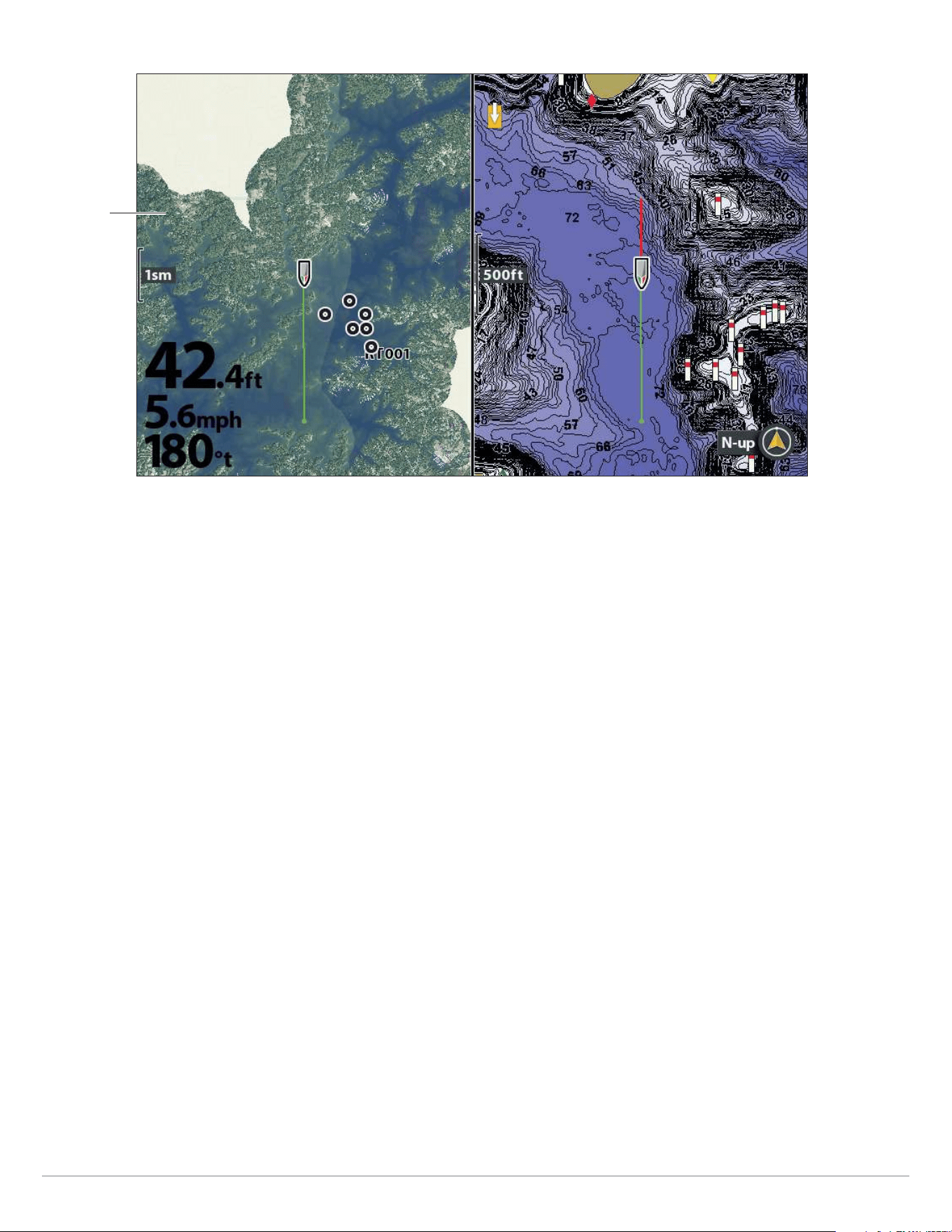
147
Customize the Chart View
Chart/Chart Combo View with Base Layer (set to 2D) and Overlay (set to Aerial)
The selected
Base Layer
will be
applied
to the left
window.
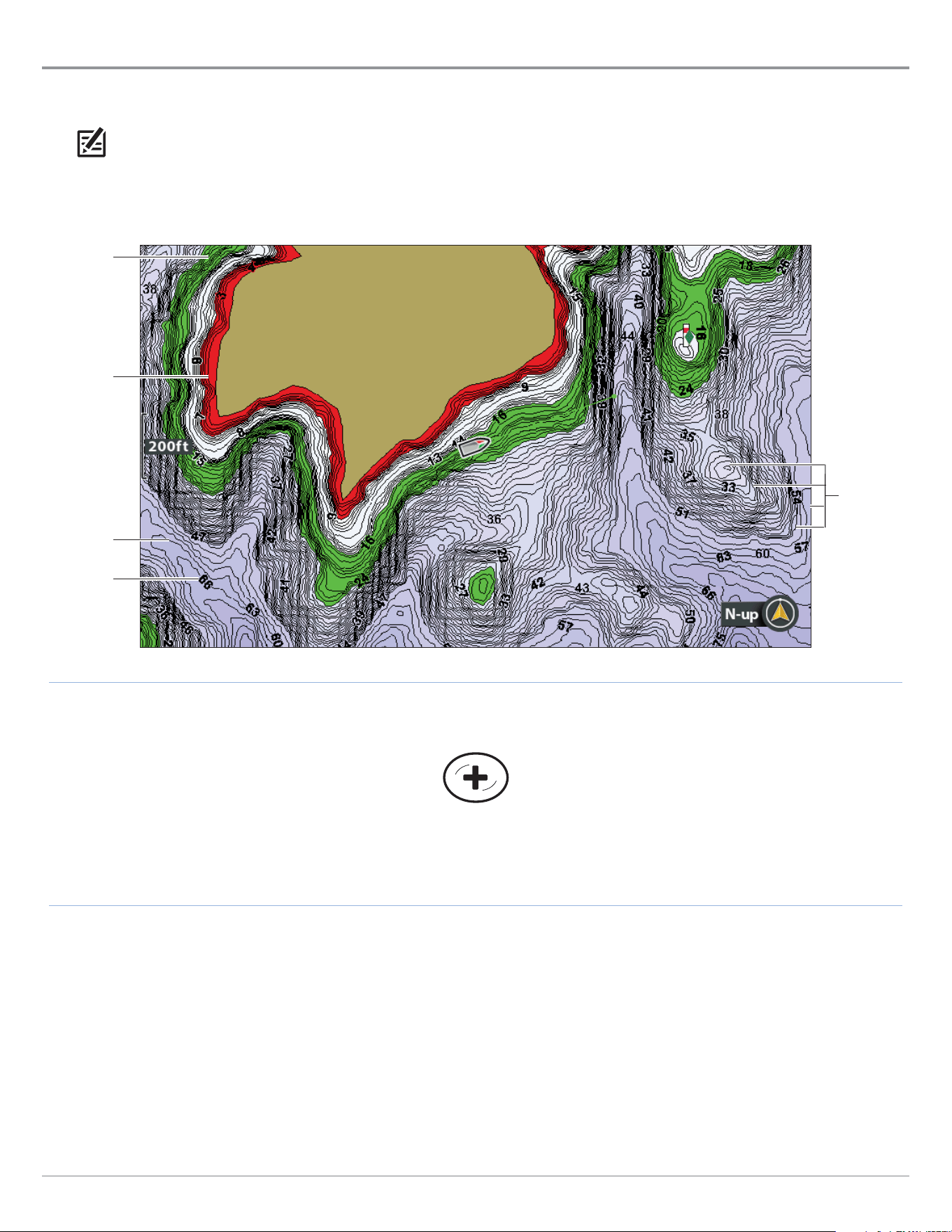
148
Customize the Chart View
Display Humminbird LakeMaster Contour Lines and Depth Ranges
When you install a LakeMaster Map Card or LakeMaster PLUS Map Card, menu options are added to the HB Chart Menu tab. You
can display or hide contour lines, highlight shallow water, and highlight a depth range on the map.
NOTE: A Humminbird LakeMaster map card must be installed and selected as the map source to enable these features. For
details and additional features related to your LakeMaster map card, visit our Web site at humminbird.com to download the
accessory guide.
See More of Contour Lines
and Depth Colors
Adjusting the LakeMaster Display Settings
depth
highlight
& depth
highlight
range
(green)
depth colors
shallow
water
highlight
(red)
contour line
depth label
(depth of
contour)

149
Customize the Chart View
Show/Hide Contour Lines
Display or hide the water contour lines in the Chart View. This feature is also affected by the Water Level Offset setting. See Select
a Map Source: Set up Humminbird LakeMaster.
1. Main Menu: Press the MENU key twice. Select the HB Chart tab.
2. Select Contour Lines.
3. Select Hidden or Visible.
Turn on Depth Colors
Set the depth shading in the Chart View to Off or shaded.
1. Main Menu: Press the MENU key twice. Select the HB Chart tab.
2. Select Depth Colors.
3. Press the RIGHT or LEFT Cursor keys to adjust the setting.
Highlight a Depth Range
Depth Highlight allows you to identify a depth in the Chart View. You can also adjust the range on each side of the depth using Depth
Highlight Range. The depth range you set is highlighted in green on the chart.
For example, if you know a certain fish is holding at 18 to 20 feet, you can set the Depth Highlight to 19 feet and the Depth Highlight
Range to +/- 1 foot. The view will show a green band from 18 to 20 feet.
1. Main Menu: Press the MENU key twice. Select the HB Chart tab.
2. Select Depth Highlight.
3. Press the RIGHT or LEFT Cursor keys to select a depth.
4. To highlight the range on both sides of the selected depth, press the DOWN Cursor key. Select Depth Highlight Range.
5. Press the RIGHT or LEFT Cursor keys to select a range.
Highlight a Shallow Water Range
When the depth is equal to or less than the amount you set, it will be highlighted in red on the Chart View.
For example, if your boat has a draft of 3 feet, set the Shallow Water Highlight to 3 feet, and a red band from 0 to 3 feet will be
shown on the map.
1. Main Menu: Press the MENU key twice. Select the HB Chart tab.
2. Select Shallow Water Highlight.
3. Press the RIGHT or LEFT Cursor keys to select a depth.
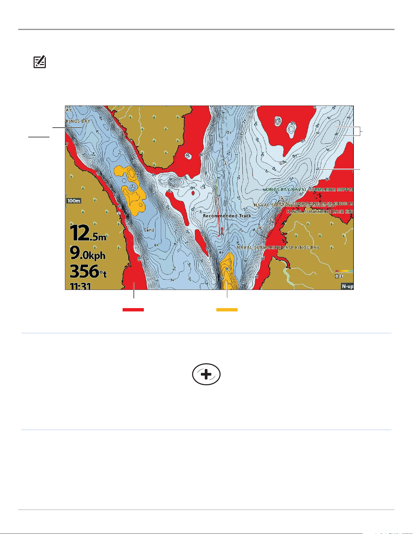
150
Customize the Chart View
Display Humminbird CoastMaster Contour Lines and Depth Ranges
When you install a CoastMaster Chart Card, menu options are added to your control head. You can display or hide contour lines,
highlight shallow water, and highlight a depth range on the map.
NOTE: A Humminbird CoastMaster map card must be installed and selected as the map source to enable these features. For
details and additional features related to your CoastMaster map card, visit our Web site at humminbird.com to download the
CoastMaster User Manual.
depth label
(depth of
contour)
depth
palette
colors
depth highlight 1 shallow water highlight
contour
lines
Adjusting the CoastMaster Display Settings
See More of Contour Lines
and Depth Colors

151
Customize the Chart View
Show/Hide Contour Lines
Display or hide the water contour lines in the Chart View. This feature is also affected by the Water Level Offset setting. See Prepare
the Control Head for Mapping: Adjust the Water Level Offset.
1. Main Menu: Press the MENU key twice. Select the HB Chart tab.
2. Select Depth/Contours.
3. Select Contour Lines.
4. Press the CHECK/INFO key or the RIGHT Cursor key to show or hide contour lines. (check mark = visible, blank = hidden)
Turn on Depth Colors
Set the depth shading in the Chart View to Off or shaded.
1. Main Menu: Press the MENU key twice. Select the HB Chart tab.
2. Select Depth/Contours.
3. Select Depth Palettes.
3. Press the CHECK/INFO key or the RIGHT Cursor key to show or hide depth colors (check mark = visible, blank = hidden)
Highlight a Depth Range
Depth Highlights allow you to select up to four depth ranges to be highlighted on the chart.
1. Main Menu: Press the MENU key twice. Select the HB Chart tab.
2. Select Depth Highlights.
3. Press the RIGHT or LEFT Cursor keys to display or hide depth highlights.
4. With depth highlights turned on, set your desired depth range by selecting Highlight 1 Min or Highlight 1 Max. Press the RIGHT
or LEFT Cursor key to adjust the setting.
5. To turn on an additional highlight, select Highlight 2.
6. Press the CHECK/INFO key or the RIGHT Cursor key to display the highlight. (check mark = visible, blank = hidden)
7. Repeat Step 2 with Highlight 2 Min and Highlight 2 Max to adjust the depth range.
8. Repeat Steps 5-7 for each additional depth highlight (up to four).
Highlight a Shallow Water Range
The Shallow Water Highlight identifies shallow waters when the depth is equal to or less than the level you set. Depth Highlights
must be turned on to enable this feature.
1. Main Menu: Press the MENU key twice. Select the HB Chart tab.
2. Select Depth Highlights.
3. Select the first Shallow Water Highlight menu option.
4. Press the CHECK/INFO key or the RIGHT Cursor key to show or hide shallow water highlights. (check mark = visible, blank =
hidden)
5. To adjust the highlighted depth level, select the second Shallow Water Highlight menu option.
6. Press the RIGHT or LEFT Cursor keys to adjust the setting.
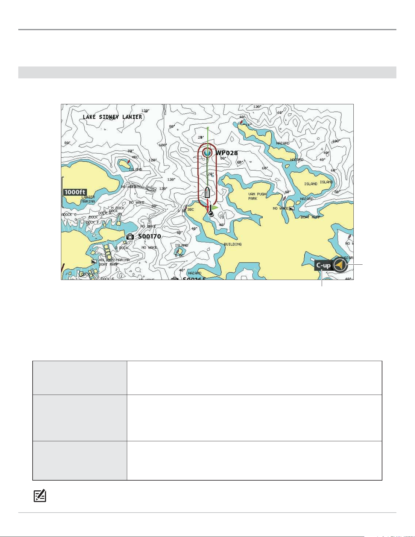
152
Change the Chart Orientation and Motion Mode
Change the Chart Orientation and Motion Mode
The Chart View pans automatically so the boat is always centered on the view. The settings in this section allow you to change the
chart orientation, zoom the view automatically, set the north reference, and see more or less of the view based on the speed or
range setting.
Set the Chart Orientation
Chart Orientation set to Course Up
north up
indicator
chart orientation
Set the Chart Orientation
1. Main Menu: Press the MENU key twice. Select the Chart tab.
2. Select Chart Orientation.
3. Select an orientation to apply to the chart.
North-Up
The chart is oriented with North up on the display, and the boat rotates according
to its heading or COG (Course Over Ground).
Head-Up
(compass or GPS required)
The boat’s current heading points up, and the chart rotates around the boat icon
so that it always points up on the view. The heading is provided by the connected
compass/heading sensor. If a compass is not connected, the boat will be oriented
according to COG (Course Over Ground).
Course-up
During navigation, the intended course or route leg is shown at the top of the view.
Objects ahead of the boat are drawn above the boat. When the boat is not navigating,
the current heading is displayed.
NOTE: The North Up Indicator will change as the orientation and data source change. To display the North Up Indicator, see
Customize the Chart View.

153
Change the Chart Orientation and Motion Mode
Set the Bearing North Reference
North Reference allows you to have the bearing displayed as True North or Magnetic North.
1. Main Menu: Press the MENU key twice. Select the Chart tab.
2. Select North Reference.
3. Select True North or Magnetic North.
Turn on/o Auto Zoom
Turn on Auto Zoom to zoom the Chart View automatically based on the speed of the boat. As the boat’s speed increases, the chart
range will increase.
NOTE: The settings in this section do not apply to the Bird’s Eye View.
1. Main Menu (Custom User Mode): Press the MENU key twice. Select the Chart tab.
2. Select Auto Zoom.
3. Select On or Off.
Zoom In/Out: If Auto Zoom is turned on, you can press the +/– ZOOM keys to see more or less of the view, and Auto Zoom will
resume after 20 seconds. To use only the +/– ZOOM keys to adjust the chart range, turn off Auto Zoom.
Turn on/o Auto Range
Turn on Auto Range to set the chart scale to the lowest range so that only the boat icon and the next waypoint in the route are
shown. If Auto Range is turned on, Auto Zoom will be turned off.
NOTE: The settings in this section do not apply to the Bird’s Eye View.
1. Main Menu (Custom User Mode): Press the MENU key twice. Select the Chart tab.
2. Select Auto Range.
3. Select On or Off.
Zoom In/Out: If Auto Range is turned on, you can press the +/– ZOOM keys to see more or less of the view, and Auto Range will
pause. To resume using Auto Range, press and hold the +/- ZOOM keys.
Turn on Vessel Oset
Vessel Offset allows you to see more of the Chart View based on the speed of the boat. Vessel Offset works with Offset Speed. When
the boat is moving below the Offset Speed setting, the boat icon will be displayed in the center of the view. When the boat is moving
at or above the Offset Speed setting, the boat icon will move to the edge of the view so more of the Chart View is shown.
1. Main Menu (Custom User Mode): Press the MENU key twice. Select the Chart tab.
2. Select Vessel Offset.
3. Select On.
4. Select Offset Speed.
5. Press the RIGHT or LEFT Cursor keys to adjust the setting.
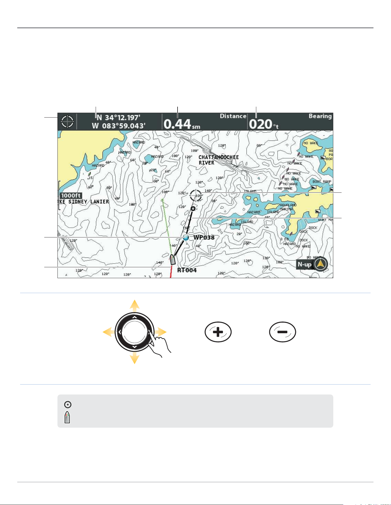
154
Navigation Overview
Navigation Overview
Your Humminbird control head allows you to mark waypoints, create a route, and start navigating. Waypoints, routes, and tracks
can be managed on-screen so you can save your favorites, edit names, and easily return to your favorite destinations.
There are many ways to start navigation or edit navigation data with your Humminbird control head. The instructions in this section
review navigation features on the chart views. To use navigation features from the Waypoint Management dialog box, see Manage
your Navigation Data.
cursor
digital
readouts
Moving the Cursor and Zooming in Chart View
cursor
current
track
cursor position distance to cursor position bearing to cursor position
Move the Cursor
ZOOM In ZOOM Out
saved route
waypoint
When the boat is stationary, it is drawn as a circle.
When the boat is in motion, it changes to a boat shape, pointed in the direction of motion.
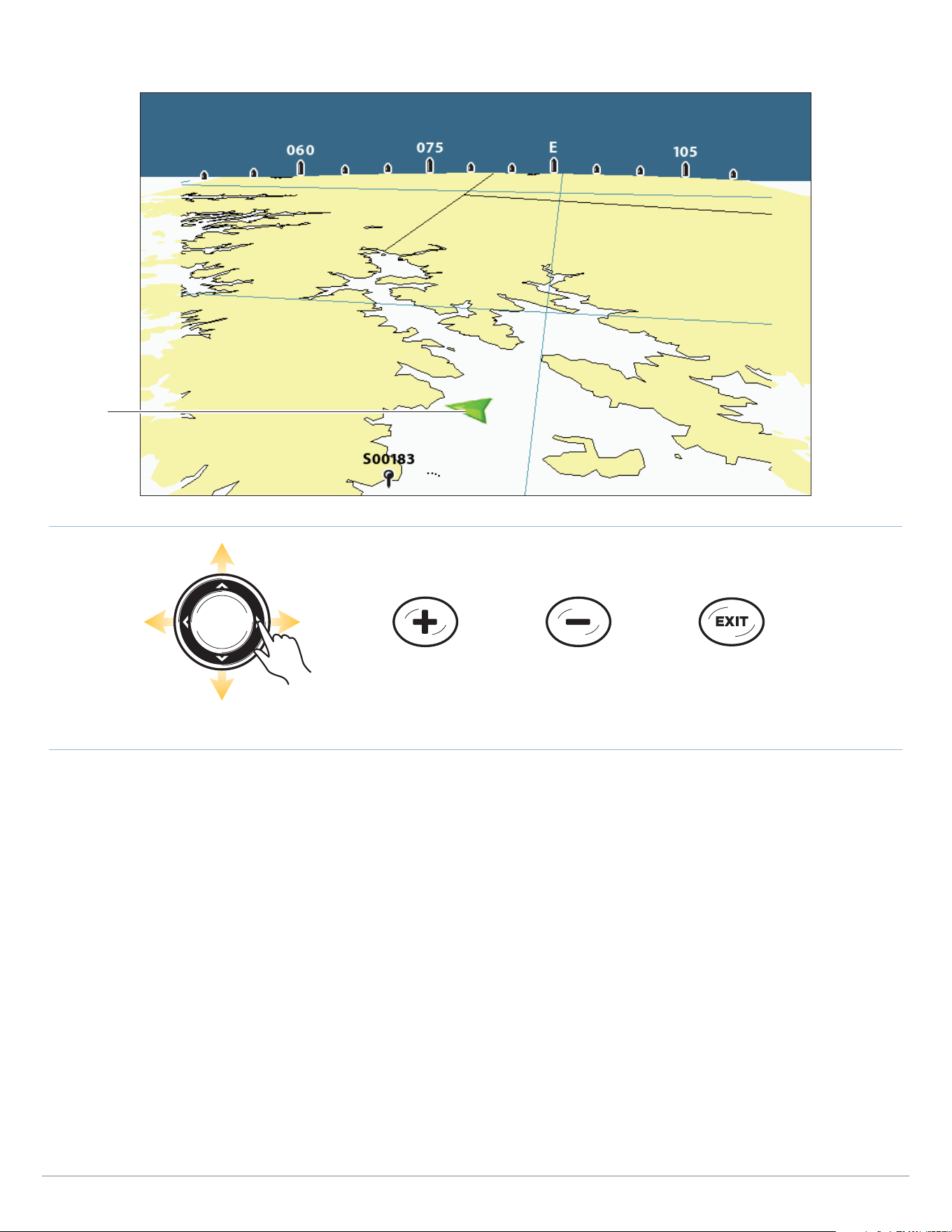
155
Navigation Overview
ZOOM In ZOOM Out
Move the Eye Point
Shifting the Eye Point and Zooming in Bird’s Eye View
boat icon
Exit
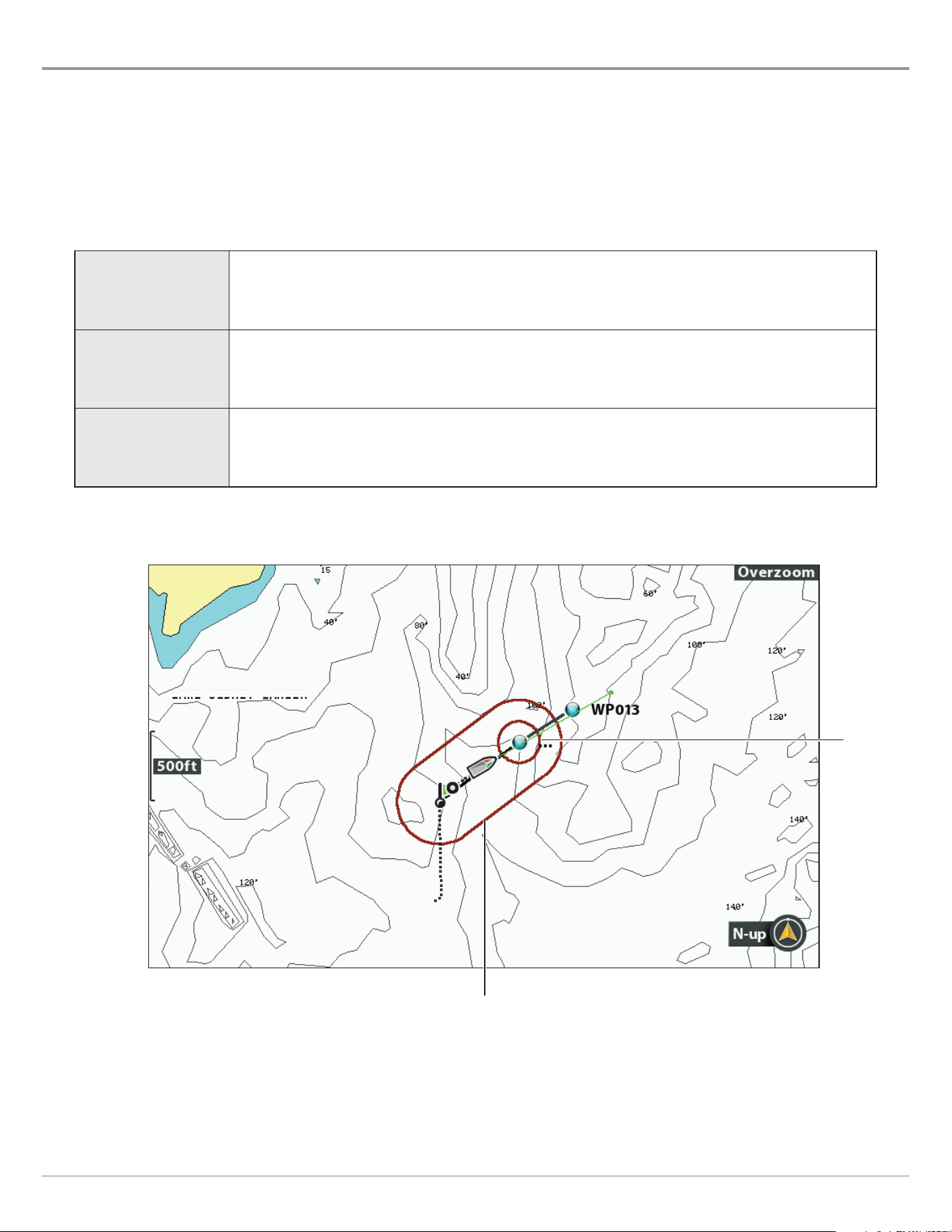
156
Navigation Alarms Overview
Navigation Alarms Overview
When an alarm is turned on, an alert will sound or display on the control head to indicate the threshold has been exceeded. When
you set the Off Course Alarm, Arrival Alarm, and Drift Alarm, the limits are shown on the Chart View.
Turn on Alarms and Adjust Settings
1. Main Menu: Press the MENU key twice. Select the Alarms tab.
2. Select an alarm menu. Press the RIGHT or LEFT Cursor keys to adjust the threshold.
Off Course Alarm
Sets how far the boat can move off course during navigation before an alarm will be triggered.
GPS required.
Arrival Alarm
Sets how close the boat must be to the destination waypoint before the alarm will be triggered.
GPS required.
Drift Alarm
Sets how far the boat can move from its anchored position outside the drift alarm perimeter
before an alarm will be triggered. GPS required.
Off Course Alarm and Arrival Circle
arrival circle
o course limits
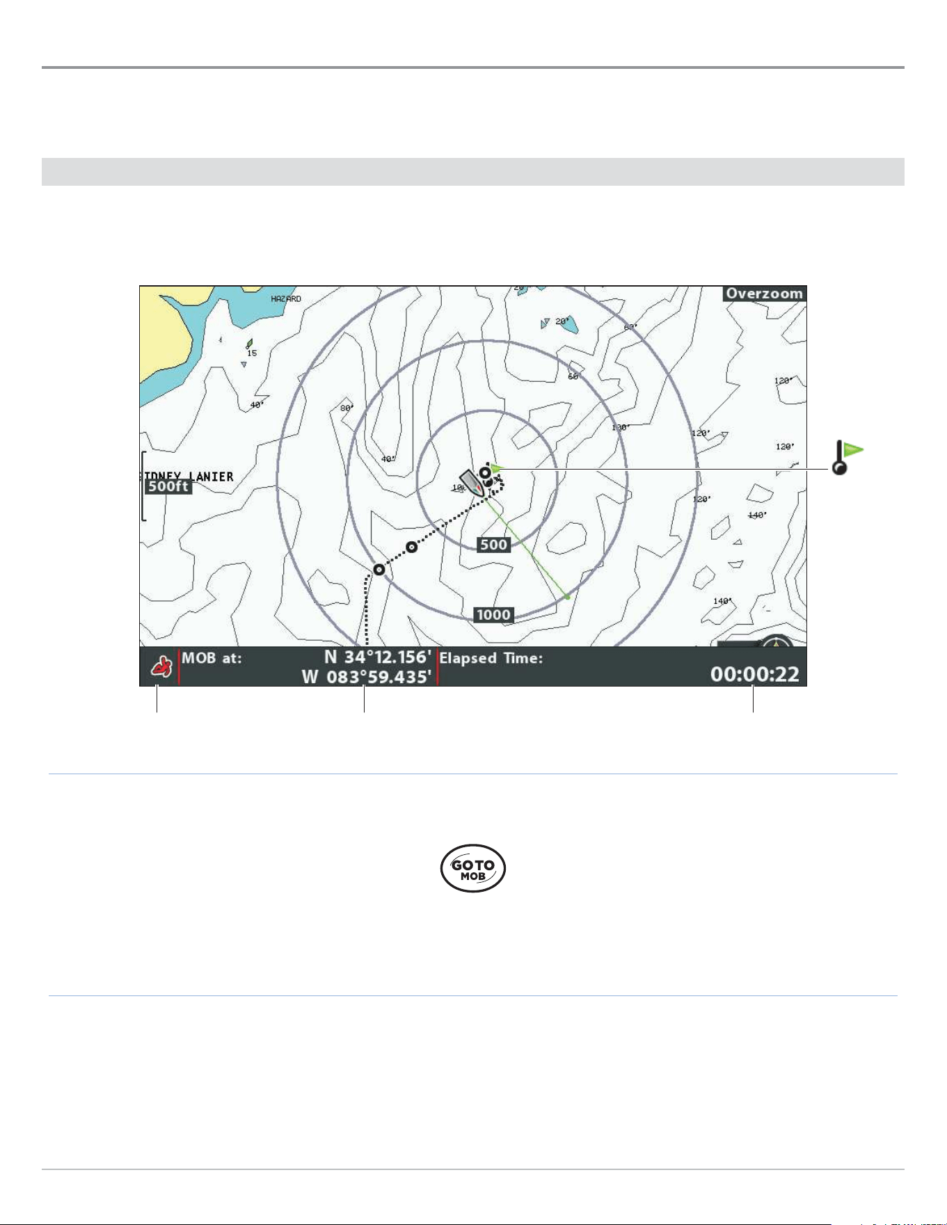
157
Man Overboard Navigation
Man Overboard (MOB) Navigation
As soon as you know that you have a man overboard (MOB), activate Man Overboard navigation to maximize the chances for a
successful rescue. Man Overboard navigation marks the approximate point where the person went overboard and starts continuous
navigation toward the Man Overboard waypoint.
Activate Man Overboard Navigation
1. Press and hold the GOTO/MOB key until Man Overboard Navigation is activated.
Press and hold to start
MOB navigation
Activating Man Overboard Navigation
Man
Overboard
marked
Elapsed time since the MOB
waypoint was marked
Man Overboard
waypoint position
Man Overboard
navigation in progress

158
Man Overboard Navigation
When Man Overboard is activated, any current navigation will be cancelled and the current route will be discarded without
notification. Man Overboard navigation will begin immediately, and you will see the following on the screen:
Chart View: The view will switch to Chart View automatically.
Man Overboard Waypoint: A waypoint is created at the boat’s current position, regardless of whether the chart cursor is active
or not.
Continuous Navigation: The control head will start continuous navigation toward the Man Overboard waypoint.
Auto Zoom: The screen magnifies to show the Man Overboard waypoint and the boat on the screen.
Cancel Man Overboard Navigation
1. Press the MENU key.
2. Select Cancel MOB Navigation.
159
Waypoints
Waypoints
Waypoints are saved latitude/longitude positions. They mark a position of interest such as your favorite fishing area, structure,
or marker buoy. The control head saves the position and allows you to edit the waypoint name, icon, and more (see Manage your
Navigation Data). You can save 2,750 waypoints to the control head.
Customize Waypoint Display Settings
You can use the waypoint settings provided by your control head, or you can customize the waypoints shown on the view. You can
also edit waypoints from the Chart View or from the Waypoint Management dialog box (see Manage your Navigation Data).
Change New Waypoint Settings
You can customize waypoint settings for all new waypoints. To edit waypoints after they’ve been marked, see Edit a Waypoint in
the Chart View or Manage your Navigation Data.
1. Main Menu: Press the MENU key twice. Select the Nav tab.
2. Select Waypoint Settings. Press the RIGHT Cursor key.
3. Use the Cursor Control key to set the following:
Icon Category Select a category to assign to new waypoints (All, Geometry, Alerts, Supplies, Navigation, etc.)
Default Waypoint
Icon
Select an icon for all new waypoints. To see the most icon options, set the Icon Category to All.
New Waypoint
Icon
Select Default, and the system will apply your settings to new waypoints.
If you choose Select, each time you mark a waypoint (see Mark Waypoints), you can change
the waypoint icon and category. See Mark and Edit Waypoints (on-the-go) in this section for
details.
4. Save: Select Save. Press the RIGHT Cursor key.
Show/Hide Casting Rings
Use Casting Rings to display a circle at a set distance around each waypoint in the Chart View. Casting rings are not applied to
decluttered waypoints (see Declutter Waypoints).
1. Main Menu: Press the MENU key twice. Select the Nav tab.
2. Select Casting Rings.
3. Use the RIGHT or LEFT Cursor keys to set how far the casting rings will be displayed from the waypoints.
Hide: Select Off to hide the casting rings.
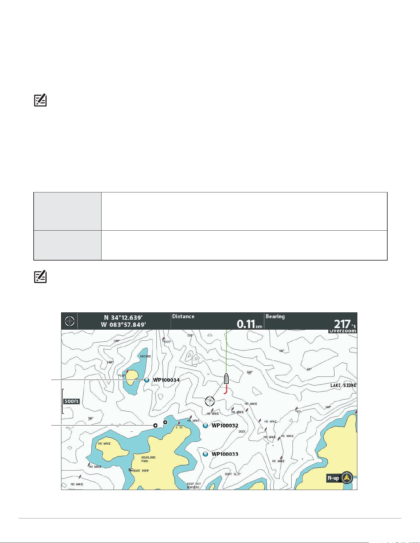
160
Waypoints
Show/Hide Waypoint Proximity Flags
Waypoint flags show the distance from the boat (or active cursor) to each waypoint. If set to visible, the waypoint flags for the ten
closest waypoints to the boat or cursor will be shown on the Chart View.
1. Main Menu (Custom User Mode): Press the MENU key twice. Select the Nav tab.
2. Select Waypoint Proximity Flags.
3. Select Hidden or Visible.
NOTE: Waypoint Proximity Flags are also influenced by the zoom level and boat speed. The flags are displayed if the chart range
is less than .5 sm and the boat is traveling less than 15 mph.
Declutter Waypoints
Use Waypoint Decluttering to control how the waypoint icon and name are displayed.
1. Main Menu (Custom User Mode): Press the MENU key twice. Select the Nav tab.
2. Select Waypoint Decluttering.
3. Select On or Off.
On
If waypoints are displayed close together, the names will be shortened, and the icons will be
displayed as small black icons. To see a decluttered waypoint at full size, select it with the
cursor, or press the +ZOOM key repeatedly.
Off Waypoint names and icons will be displayed at regular size.
NOTE: To increase the text size, see Customize the Chart View: Increase the Text Size.
Waypoints and Decluttered Waypoints
decluttered
waypoint
waypoint
at full size
with name
displayed
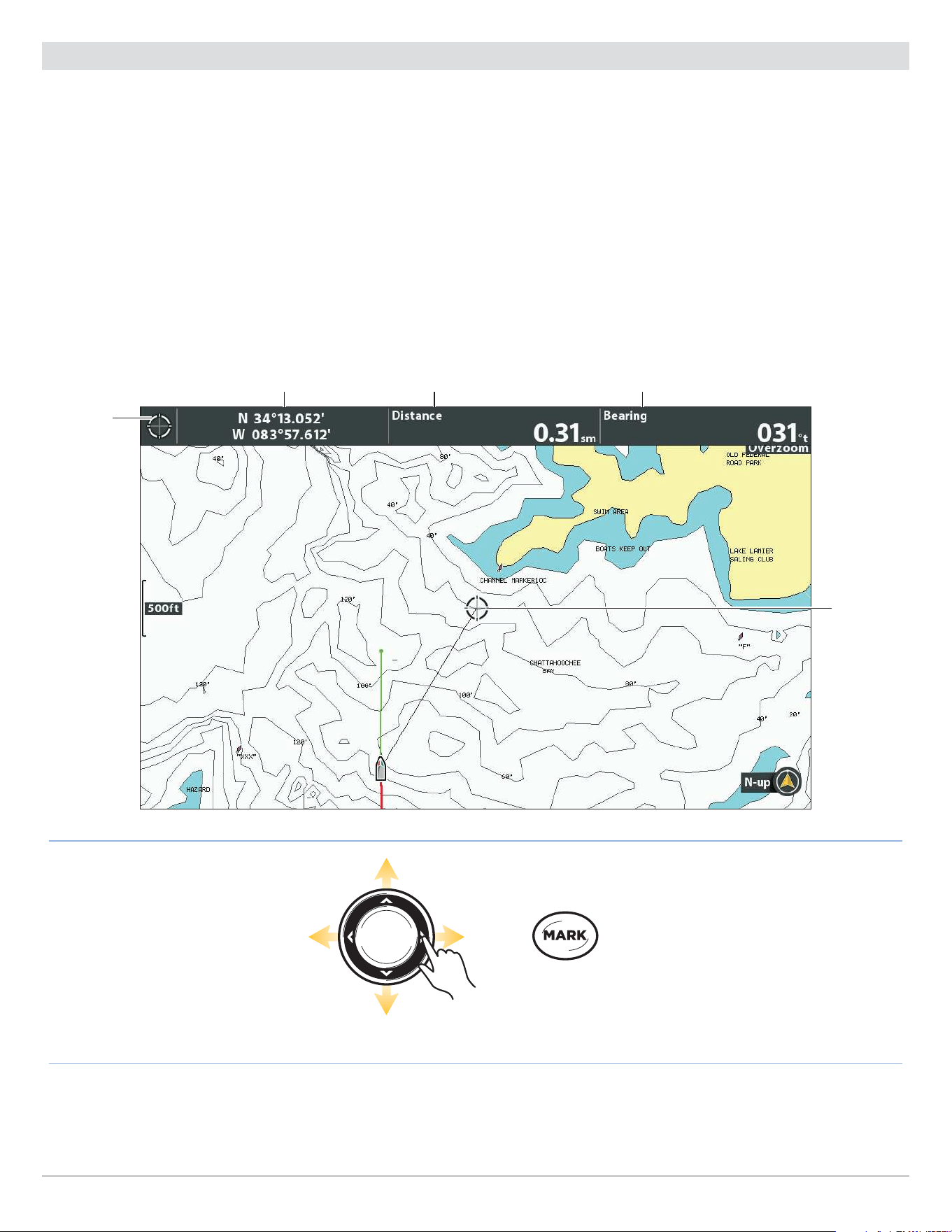
161
Waypoints
Mark Waypoints
Waypoints can be marked at the boat position or cursor position. To edit the waypoint, see Edit a Waypoint in the Chart View or
Manage your Navigation Data.
Mark a Waypoint at the Boat Position
1. Press the MARK key.
Mark a Waypoint at the Cursor Position
1. Use the Cursor Control key to move the cursor to a position on the chart.
2. Press the MARK key twice.
Press Twice to
Mark a Waypoint
Move the Cursor
Marking a Waypoint
cursor
digital
readouts
cursor
cursor position distance to cursor position bearing to cursor position

162
Waypoints
Select a Waypoint in the Chart View
You can select a saved waypoint using the menu system or using the cursor on the Chart View.
Select a Saved Waypoint on the Chart View
1. Use the Cursor Control key to move the cursor to a waypoint on the Chart View.
Edit: Press the MENU key. Select the waypoint from the menu. Press the RIGHT Cursor key. Select Edit.
More Info: Press the CHECK/INFO key.
Start Navigation: Press the GOTO key twice.
2. Exit Cursor: Press the EXIT key.
Select the Last Saved Waypoint
1. Press the MENU key.
2. Select the waypoint name from the X-Press Menu.
3. Press the RIGHT Cursor key.
4. Select a menu from the waypoint menu.
Search and Select a Saved Waypoint
Use these instructions to search quickly for a waypoint, which is helpful if you cannot locate it on the Chart View.
1. Chart X-Press Menu: With a Chart View displayed on-screen, press the MENU key once.
2. Select Cursor to Waypoint. Press the RIGHT Cursor key.
3. Use the Cursor Control key to sort the list.
4. Select the waypoint name from the menu. Press the RIGHT Cursor key.
5. Press the EXIT key once.
6. The cursor will select the waypoint on the Chart View.
Edit: Press the MENU key. Select the waypoint from the menu. Press the RIGHT Cursor key. Select Edit.
More Info: Press the CHECK/INFO key.
Start Navigation: Press the GOTO key twice.
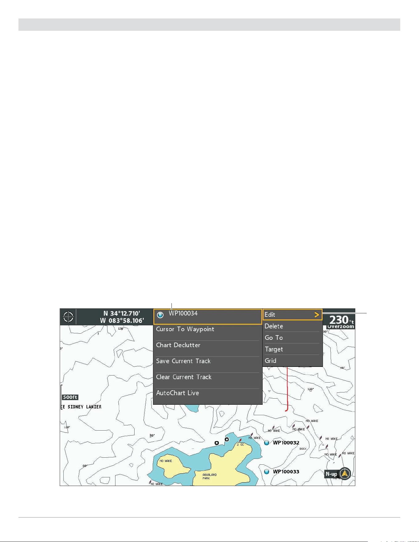
163
Waypoints
Edit a Waypoint
You can edit a waypoint as you mark it or after it is saved. The instructions in this section show you how to edit a waypoint in the
Chart View. To edit a waypoint or a group of waypoints from the Waypoint Management dialog box, see Manage your Navigation
Data.
Mark and Edit Waypoints (on-the-go)
Use the instructions in this section to edit a waypoint as soon as you mark it.
1. Setup: See Change New Waypoint Settings. Set the New Waypoint Icon menu to Select.
2. Press the MARK key.
OR
Use the Cursor Control key to move the cursor to a position. Press the MARK key twice.
3. Edit: When you mark a waypoint, the Waypoint Settings menu will display so you can edit the waypoint.
No Changes: To proceed without making changes, press the MARK key (again).
Edit a Waypoint in the Chart View
Use these instructions to edit a waypoint from the Chart View. You can also edit waypoints in the Waypoint Management dialog box
(see Manage your Navigation Data).
1. Use the Cursor Control key to move the cursor to a waypoint on the Chart View.
2. Press the MENU key.
3. Select the waypoint name from the X-Press Menu. Press the RIGHT Cursor key.
4. Select Edit. Press the RIGHT Cursor key.
Editing a Waypoint from the X-Press Menu
selecting
Edit from
the waypoint
submenu
selected waypoint
5. Use the Edit Waypoint menu to edit the waypoint name, icon, and more (see Manage your Navigation Data for more
information).

164
Waypoints
Changing the Waypoint Name
Move from Space to Space Select a Letter, Number, or Symbol
Save
6. Save: Select Save. Press the RIGHT Cursor key.
7. Close: Press the EXIT key.
Change the Waypoint Position in the Chart View
1. Use the Cursor Control key to move the cursor to a waypoint on the Chart View.
2. Press the MENU key.
3. Select the waypoint name from the X-Press Menu. Press the RIGHT Cursor key.
4. Select Edit. Press the RIGHT Cursor key.
5. Select the latitude position. Press the RIGHT Cursor key.
6. Use the Cursor Control key to enter a new position.
7. Save: Press the CHECK/INFO key.
8. Repeat steps 5 through 7 to change the longitude position.
9. Close: Press the EXIT key.
10. Save: Select Save. Press the RIGHT Cursor key.
Show/Hide a Waypoint Target
Use the instructions in this section to display a target around a selected waypoint.
Display a Target
1. Use the Cursor Control key to move the cursor to a waypoint on the Chart View.
2. Press the MENU key.
3. Select the waypoint name from the X-Press Menu. Press the RIGHT Cursor key.
4. Select Target. Press the RIGHT Cursor key.
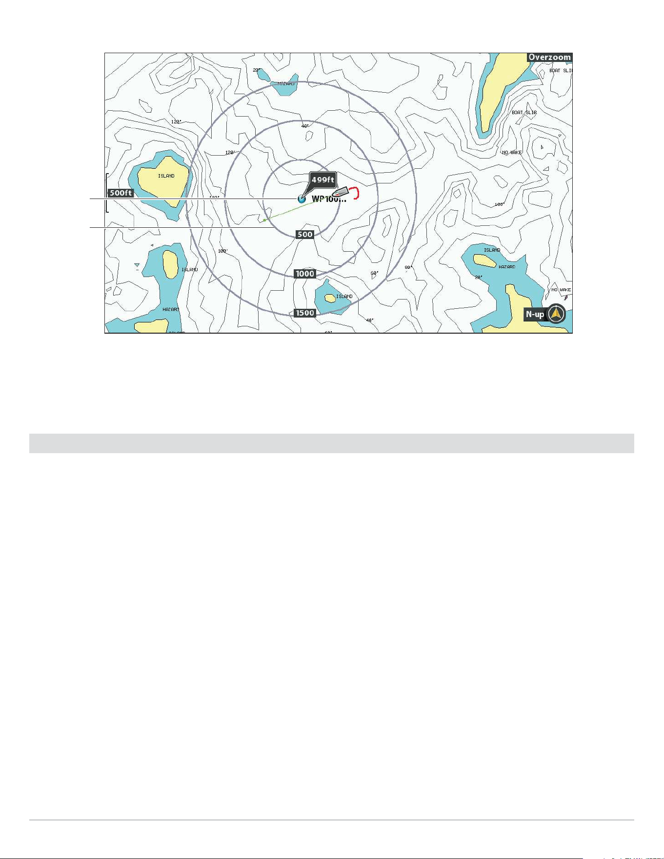
165
Waypoints
Waypoint with Target Displayed
selected
waypoint
target
Remove a Target
1. Chart X-Press Menu: With a Chart View displayed on-screen, press the MENU key once.
2. Select Remove Target. Press the RIGHT Cursor key.
Show/Hide a Waypoint Trolling Grid
Use the instructions in this section to display a trolling grid on a selected waypoint.
Display a Trolling Grid
1. Use the Cursor Control key to move the cursor to a waypoint on the Chart View.
2. Press the MENU key.
3. Select the waypoint name from the X-Press menu. Press the RIGHT Cursor key.
4. Select Grid. Press the RIGHT Cursor key.
Adjust the Trolling Grid Rotation
1. Main Menu: Press the MENU key twice. Select the Nav tab.
2. Select Trolling Grid Rotation.
3. Press the RIGHT or LEFT Cursor keys to adjust the setting.
Remove a Trolling Grid
1. Chart X-Press Menu: With a Chart View displayed on-screen, press the MENU key once.
2. Select Remove Grid. Press the RIGHT Cursor key.
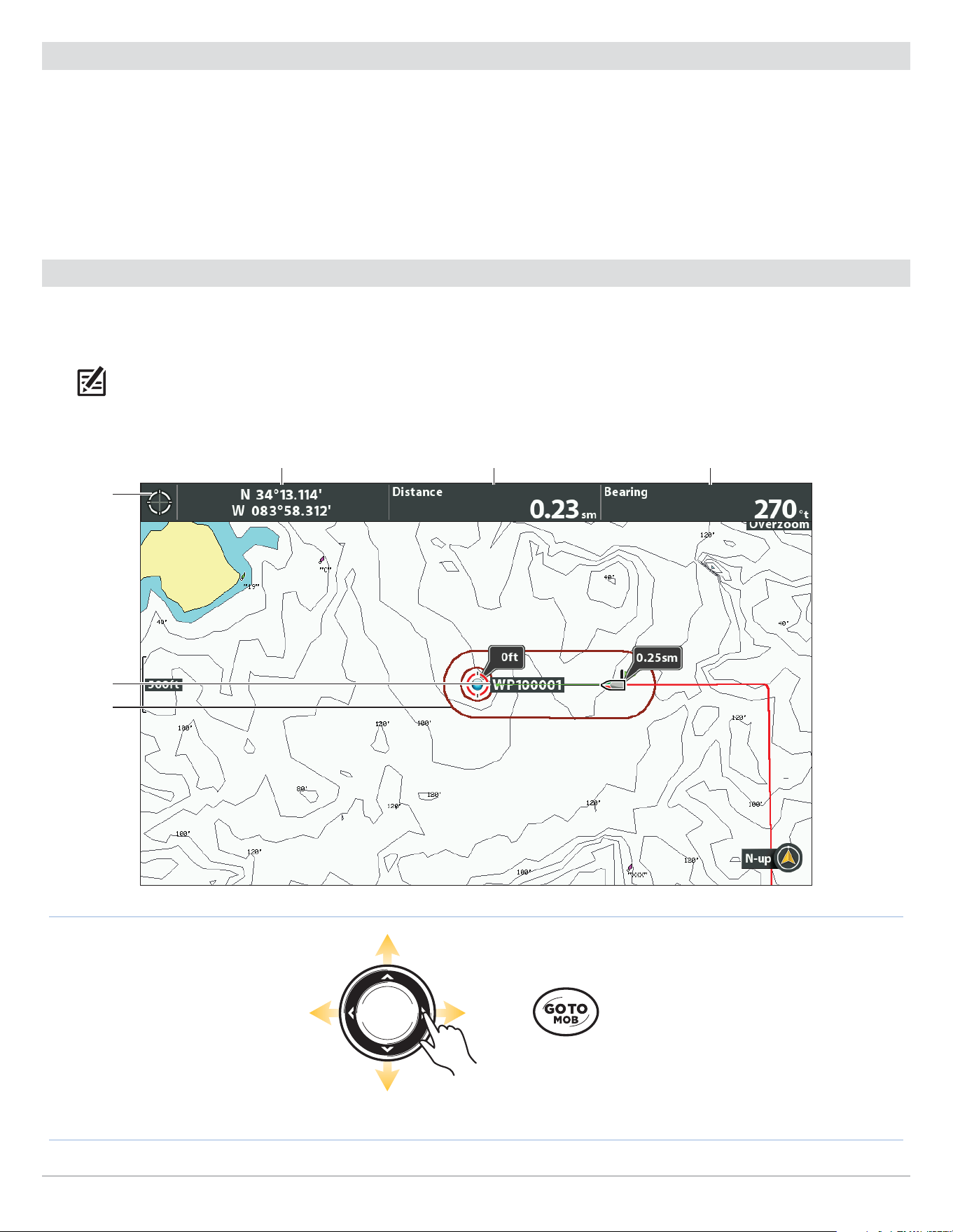
166
Waypoints
Delete a Waypoint in the Chart View
Use the following instructions to select a waypoint and delete it.
1. Use the Cursor Control key to move the cursor to a waypoint on the Chart View.
2. Press the MENU key.
3. Select the waypoint name from the X-Press Menu. Press the RIGHT Cursor key.
4. Select Delete. Press the RIGHT Cursor key.
Navigate to a Waypoint or Position
1. Use the Cursor Control key to move the cursor to a waypoint or position on the chart.
2. Press the GOTO key twice.
NOTE: If you are starting navigation to the cursor position, a waypoint will be marked when you press the GOTO key.
Press Twice to
Start Navigation
Move the Cursor
Starting Navigation to the Cursor Position
cursor
digital
readouts
destination
waypoint
name
o course
limits
cursor position distance to cursor position bearing to cursor position

167
Waypoints
Navigate to a Saved Position
If you press the GOTO key, you can choose to start navigation from a list of saved waypoints and routes.
1. Press the GOTO key.
2. Select Nav Data. Press the RIGHT Cursor key.
3. Use the Cursor Control key to select a saved waypoint or route.
4. Press the RIGHT Cursor key to start navigation.
Navigate Continuously Around a Waypoint
Continuous Navigation Mode allows you to continue to navigate and fish around a selected waypoint, even if you pass over it multiple
times.
1. Main Menu: Press the MENU key twice. Select the Nav tab.
2. Select Continuous Navigation Mode.
3. Select On.
4. Press the EXIT key repeatedly until the menu system is closed.
5. Use the Cursor Control key to move the cursor to a waypoint.
6. Press the GOTO key twice.
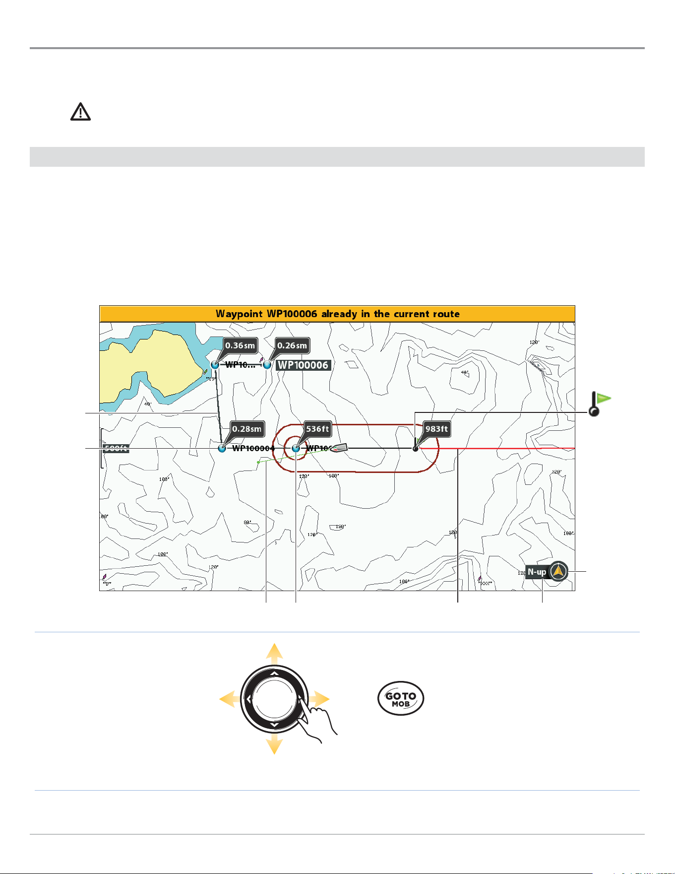
168
Routes
Routes
Routes link two or more waypoints together to create a path for navigation. A route represents your intended navigation and shows
the shortest path from each data point to the next. The distance between each waypoint is a route leg. You can save 47 routes
(with 50 waypoints each) to the control head.
WARNING! You should always be aware of your surroundings and watch for any potential obstacles.
Create a Route and Start Navigation
Use the instructions in this section to connect waypoints and start navigation immediately. To create a route from the Waypoint
Management dialog box, see Manage your Navigation Data.
1. Use the Cursor Control key to move the cursor to a waypoint or position on the chart.
2. Press the GOTO key twice.
3. Repeat steps 1 and 2 to add more waypoints to the route.
Press Twice to
Start Navigation
Move the Cursor
Creating and Navigating a Route
2nd
waypoint
route leg
north up
indicator
chart orientation1st waypoint current trackcourse projection line
route start
point
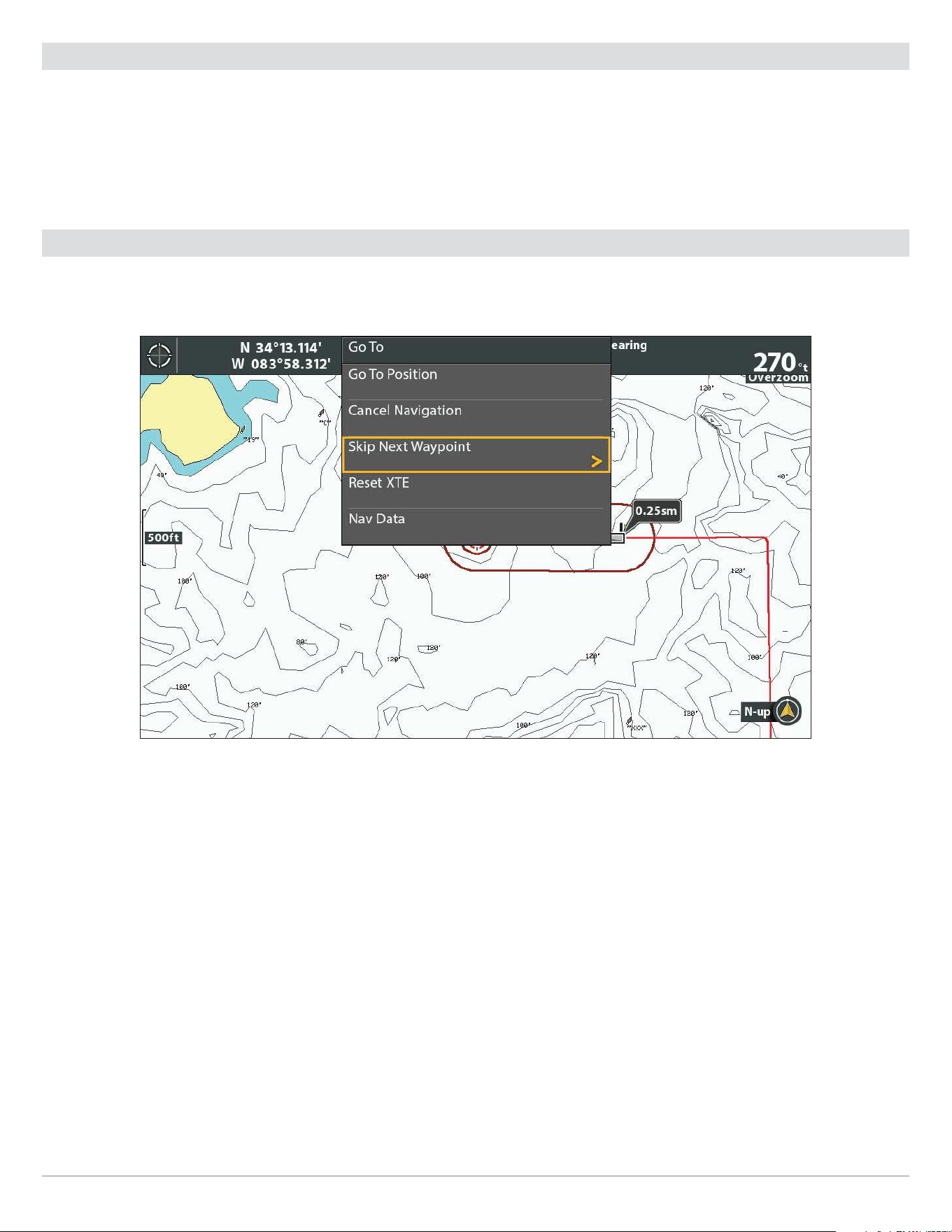
169
Routes
Save the Current Route
A route must have at least two waypoints to be saved as a route.
1. Chart X-Press Menu: With a Chart View displayed on-screen, press the MENU key once.
2. Select Save Current Route. Press the RIGHT Cursor key.
3. Follow the on-screen prompts to save or discard the route.
Change the Route During Navigation
The X-Press Menu allows you to make changes to the route while you are navigating it.
Skipping a Waypoint During Navigation
Skip a Waypoint
1. Chart X-Press Menu: With a Chart View or Bird’s Eye View displayed on-screen, press the GOTO key once.
2. Select Skip Next Waypoint.
3. Press the RIGHT Cursor key.
Change the Route Order
The route must be saved before you can change the travel order (see Save the Current Route).
1. Chart X-Press Menu: With a Chart View or Bird’s Eye View displayed on-screen, press the MENU key once.
2. Select the route name. Press the RIGHT Cursor key.
3. Select Travel Forward or Travel Reverse.
4. Press the RIGHT Cursor key.

170
Routes
Reset XTE (Cross Track Error)
Use Reset XTE to recalculate the cross track error (XTE) from the boat’s current position to the next waypoint in the route.
For example, if you’ve deviated from a route to navigate around an island, select Reset XTE to update the control head’s course
calculations from the current boat position instead of from the previous waypoint in the route.
1. Chart X-Press Menu: With a Chart View or Bird’s Eye View displayed on-screen, press the GOTO key once.
2. Select Reset XTE.
3. Press the RIGHT Cursor key.
Cancel Navigation
1. Chart X-Press Menu: With a Chart View displayed on-screen, press the MENU key once.
2. Select Cancel Navigation. Press the RIGHT Cursor key.
3. Follow the on-screen prompts to cancel navigation and save the route.
Start Navigation on a Saved Route
Use the cursor to select a waypoint in a saved route, and you can start navigation to it. You can also choose the order of navigation.
Start Navigation on a Saved Route
1. Use the Cursor Control key to move the cursor to a waypoint on a route.
If you select the first waypoint in the route, the route will turn red.
2. Press the GOTO key.
3. Select a travel order.
Go To Point Start navigation to the selected waypoint only.
Forward from
Point
Start navigation to the selected waypoint and continue traveling the route forward from there.
Reverse from
Point
Start navigation to the selected waypoint and travel the route in reverse from there.
Travel Forward
Start navigation to the first waypoint in the route and continue traveling the route forward
from there.
Travel Reverse Start navigation to the last waypoint in the route and travel the route in reverse from there.
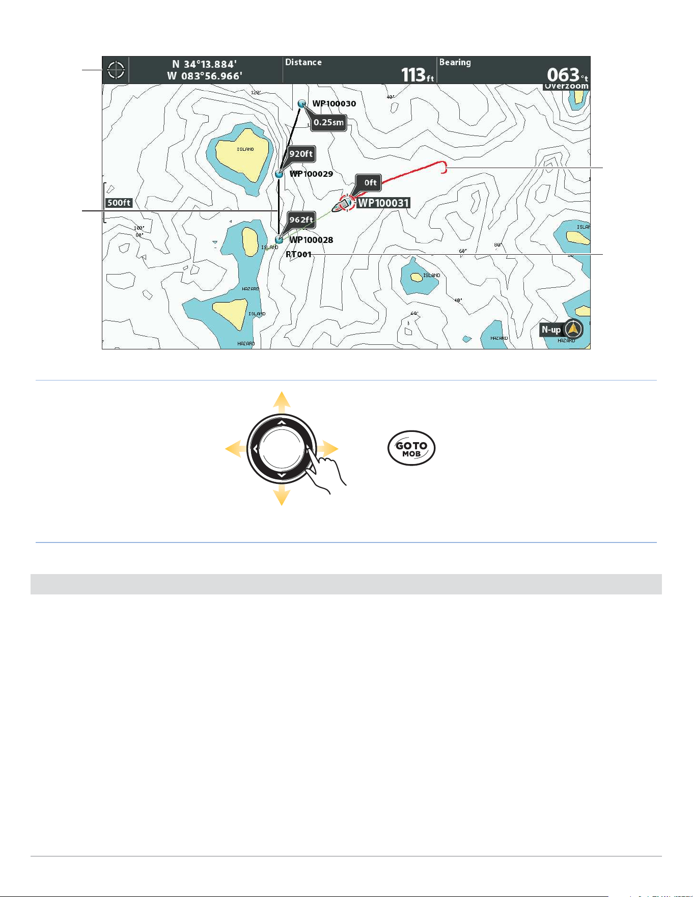
171
Routes
Open the Go To Menu
Select a Waypoint
on a Route
cursor
digital
readouts
Selecting a Saved Route on the Chart View
current
track
selected
route name
selected
route
(red)
Navigate to a Saved Position
If you press the GOTO key, you can choose to start navigation from a list of saved waypoints and routes.
1. Press the GOTO key.
2. Select Nav Data. Press the RIGHT Cursor key.
3. Use the Cursor Control key to select a saved waypoint or route.
4. Press the RIGHT Cursor key to start navigation.
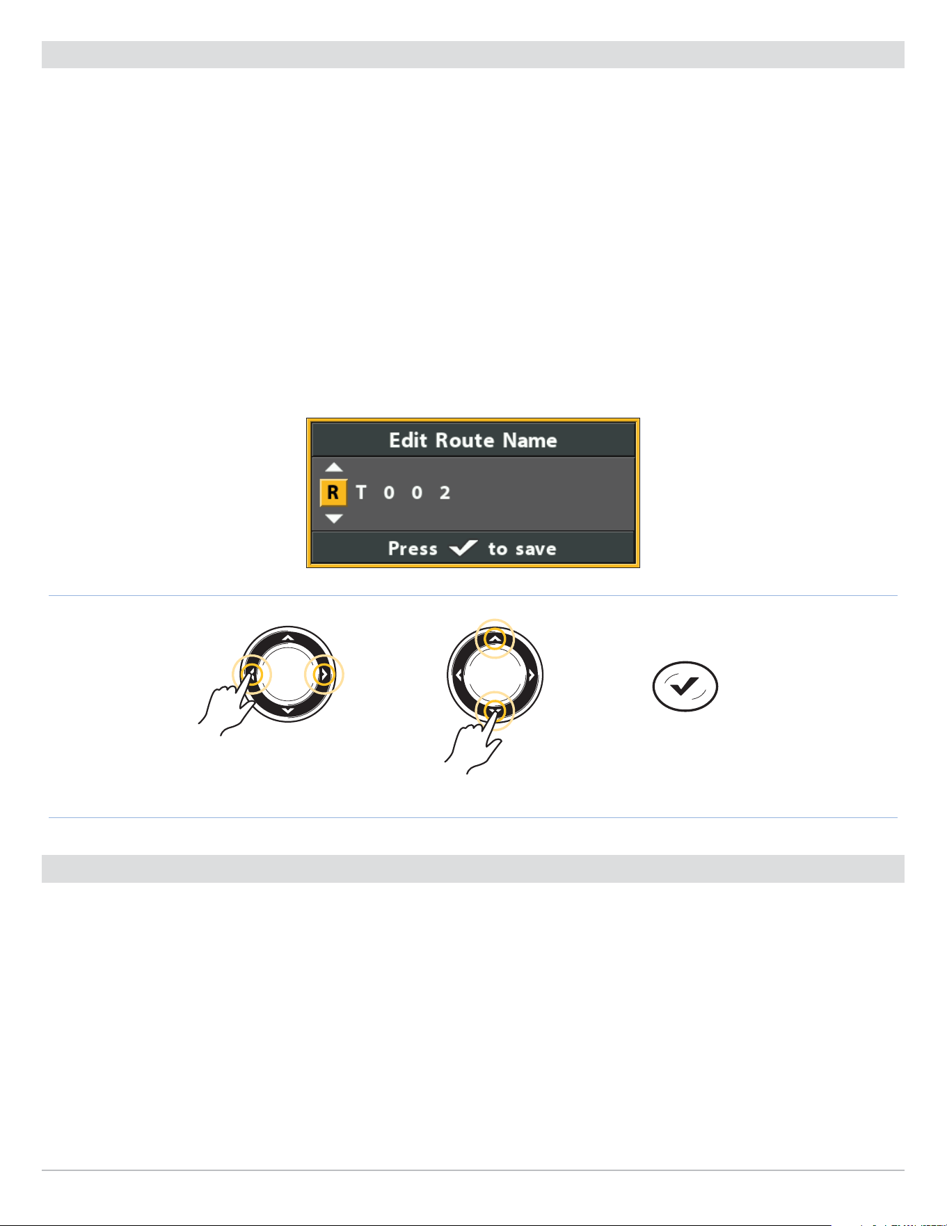
172
Routes
Edit a Saved Route
You can edit the route name and display it or hide it on the Chart View. To edit routes from the Waypoint Management dialog box,
see Manage your Navigation Data.
1. Use the Cursor Control key to move the cursor to a waypoint on the route. Press the MENU key.
OR
If the route was saved recently, you don’t have to select it first. Press the MENU key.
2. Select the route name from the X-Press Menu. Press the RIGHT Cursor key.
3. Select Edit. Press the RIGHT Cursor key.
4. Use the Cursor Control key to change the route name.
Visibility: Select Visible or Hidden.
5. Save: Select Save. Press the RIGHT Cursor key.
Changing the Route Name
Move from Space to Space Select a Letter, Number, or Symbol
Save
Delete a Saved Route
You can delete a route from the Chart View or the Waypoint Management dialog box. To delete a route from the Waypoint
Management dialog box, see Manage your Navigation Data.
1. Use the Cursor Control key to move the cursor to a waypoint on the route. Press the MENU key.
OR
If the route was saved recently, you don’t have to select it first. Press the MENU key.
2. Select the route name from the X-Press Menu. Press the RIGHT Cursor key.
3. Select Delete. Press the RIGHT Cursor key.
4.
Follow the on-screen prompts to delete the route.
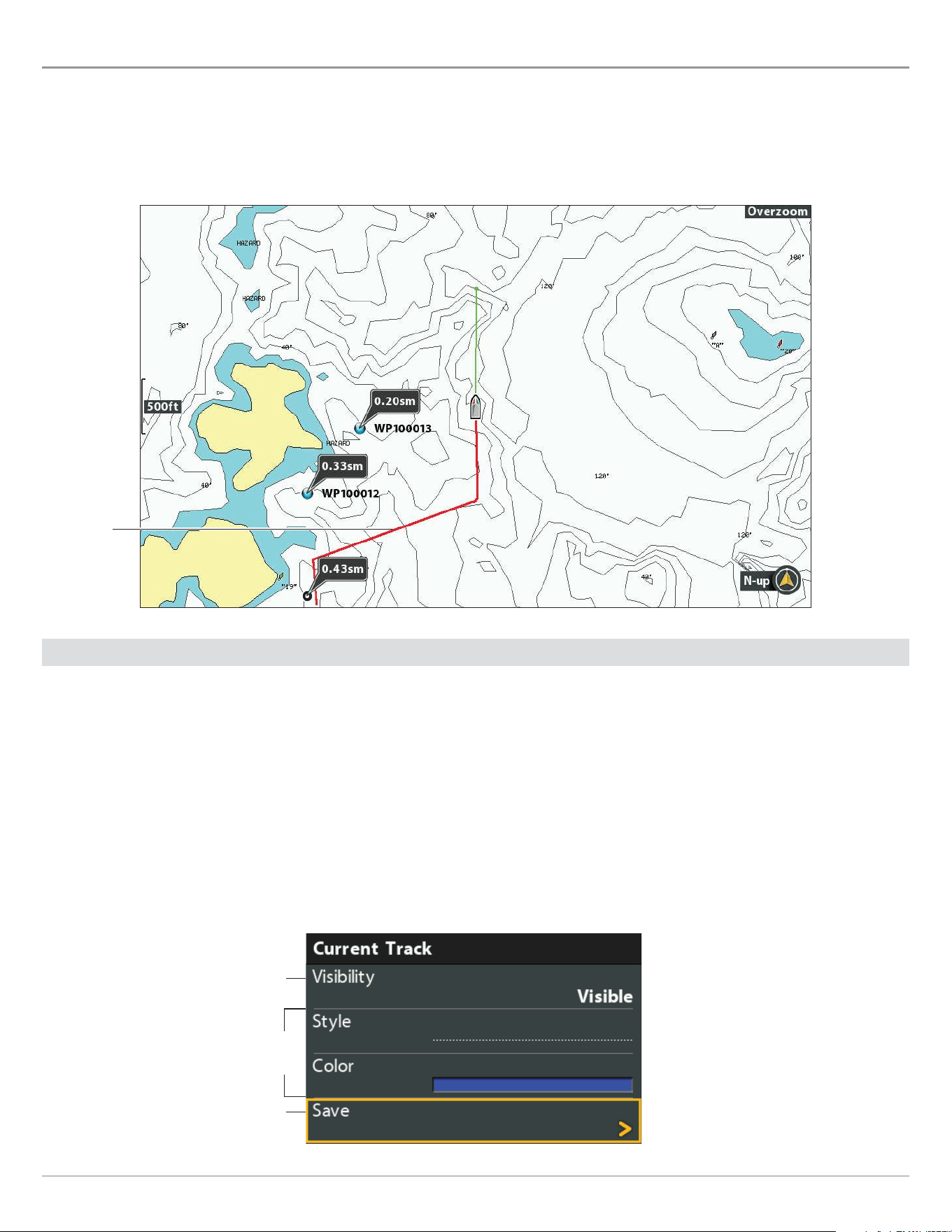
173
Tracks
Tracks
A track is a collection of track points that contains the boat’s detailed position history at set intervals. The Current Track shows the
position history since the control head was powered on. You can clear the Current Track or save it at any time. To change the track
point interval, edit saved tracks, and create track settings, see Manage your Navigation Data. You can save 50 tracks (each with
20,000 track points) to the control head.
Chart View with the Current Track Displayed
current
track
Change New Track Settings
You can use the track settings provided by your control head, or you can customize the tracks shown on the view. You can also edit
tracks from the Chart View or from the Waypoint Management dialog box (see Manage your Navigation Data).
Set the Default Track Appearance
Use the instructions in this section to customize settings for all new tracks. To edit tracks after they’ve been saved, see Edit the
Current Track and Manage your Navigation Data.
1. Main Menu: Press the MENU key twice. Select the Nav tab.
2. Select Saved Track Defaults. Press the RIGHT Cursor key.
Changing the Current Track Appearance
save
hidden or visible
To display the
color options,
select a line style.
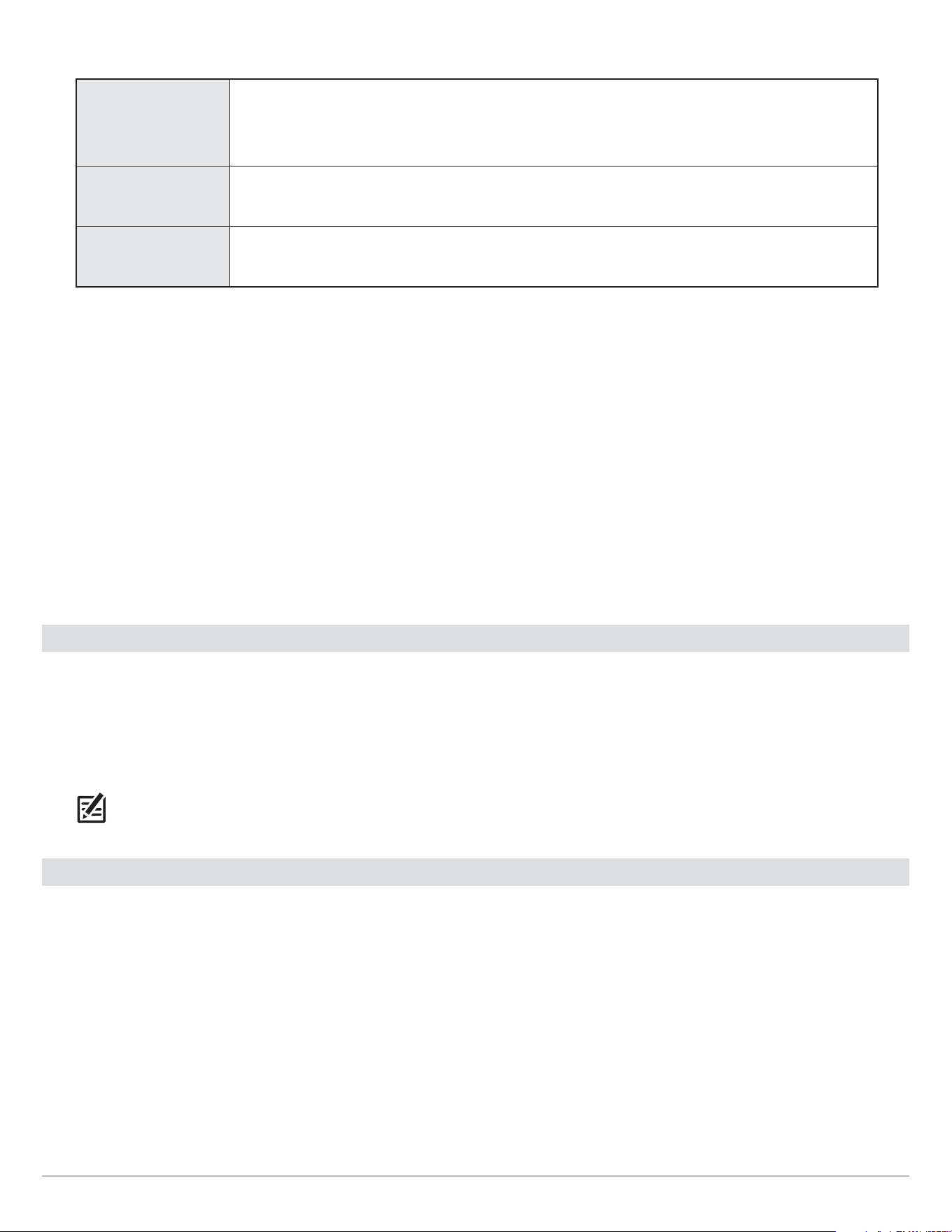
174
Tracks
3. Use the Cursor Control key to change the following:
Visibility
To show all tracks on the chart, select Visible. To hide tracks, select Hidden. If you choose
Hidden, the control head continues to save trackpoints, but the track will not be displayed on
the view.
Style Select a line style (dotted, line, etc.) for all new tracks.
Color If you select a line style, you can also select the line color.
4. Save: Select Save. Press the RIGHT Cursor key.
Change the Trackpoint Interval and Trackpoint Min Distance
Trackpoint Interval and Track Min (minimum) Distance work together to add a trackpoint to the current track. During slow travel or
drift, setting both Trackpoint Interval and Track Min Distance to small values increases the track resolution. Setting the menus to
higher values will cause the track to extend back further in time, but it will be less detailed.
1. Main Menu (Custom User Mode): Press the MENU key twice. Select the Nav tab.
2. Select Trackpoint Interval.
3. Press the RIGHT or LEFT Cursor keys to adjust the setting.
4. Select Track Min Distance.
5. Press the RIGHT or LEFT Cursor keys to adjust the setting.
Save the Current Track
Use the following instructions to save the current track and start a new track.
1. Chart X-Press Menu: With a Chart View displayed on-screen, press the MENU key once.
2. Select Save Current Track. Press the RIGHT Cursor key.
3. Follow the on-screen prompts to save or discard the track.
NOTE: It is important to save the track before powering off the control head.
Edit the Current Track
Use the following instructions to edit the current track. To edit a saved track, see Manage your Navigation Data.
1. Main Menu: Press the MENU key twice. Select the Nav tab.
2. Select Current Track. Press the RIGHT Cursor key.
3. Select Appearance.
4. Use the Cursor Control key to change the visibility, style, and color.
See Change New Track Settings for details.
5. Save: Select Save. Press the RIGHT Cursor key.

175
Tracks
Clear the Current Track
Use the following instructions to clear the current track on the
view
and start a new track at the present boat position.
1. Chart X-Press Menu: With a Chart View displayed on-screen, press the MENU key once.
2. Select Clear Current Track.
3. Press the RIGHT Cursor key.
Show/Hide the Current Track
The current track is shown on the Chart View automatically. To
hide or show the current track,
use the following instructions. To show
or hide a saved track, see Manage your Navigation Data.
1. Main Menu: Press the MENU key twice. Select the Nav tab.
2. Select Current Track. Press the RIGHT Cursor key.
3. Select Appearance.
4. Select Visibility.
5. Select Hidden or Visible.
6. Save: Select Save. Press the RIGHT Cursor key.
Stop Tracking
Use the instructions in this section to turn off tracking. If you turn off tracking, the unit will not save trackpoints.
1. Main Menu: Press the MENU key twice. Select the Nav tab.
2. Select Current Track. Press the RIGHT Cursor key.
3. Select Stop Tracking. Press the RIGHT Cursor key.
To start tracking, select the Nav tab > Current Track > Start Tracking.
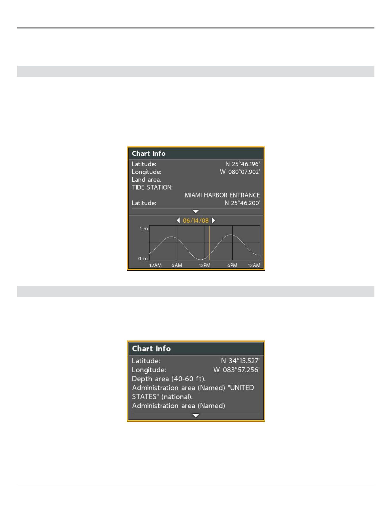
176
Search
Search
There are many ways to search the area for ports, tide stations, and current stations. You can also search for information based
on the cursor position. The search options and the search area distance are determined by the installed map card and selected
map source.
Search by Nearest Port, Tide Station, or Current Station
The control head must have a separate-purchase map card installed to enable the features in this section.
1. Press the CHECK/INFO key.
2. Select Nearest Port, Nearest Tide Station, or Nearest Current Station.
3. Press the RIGHT Cursor key.
Chart Info: Tide Station
Search by Cursor Position
1. Use the Cursor Control key to move the cursor to a waypoint or position on the chart.
2. Press the CHECK/INFO key.
Chart Info: Cursor Position
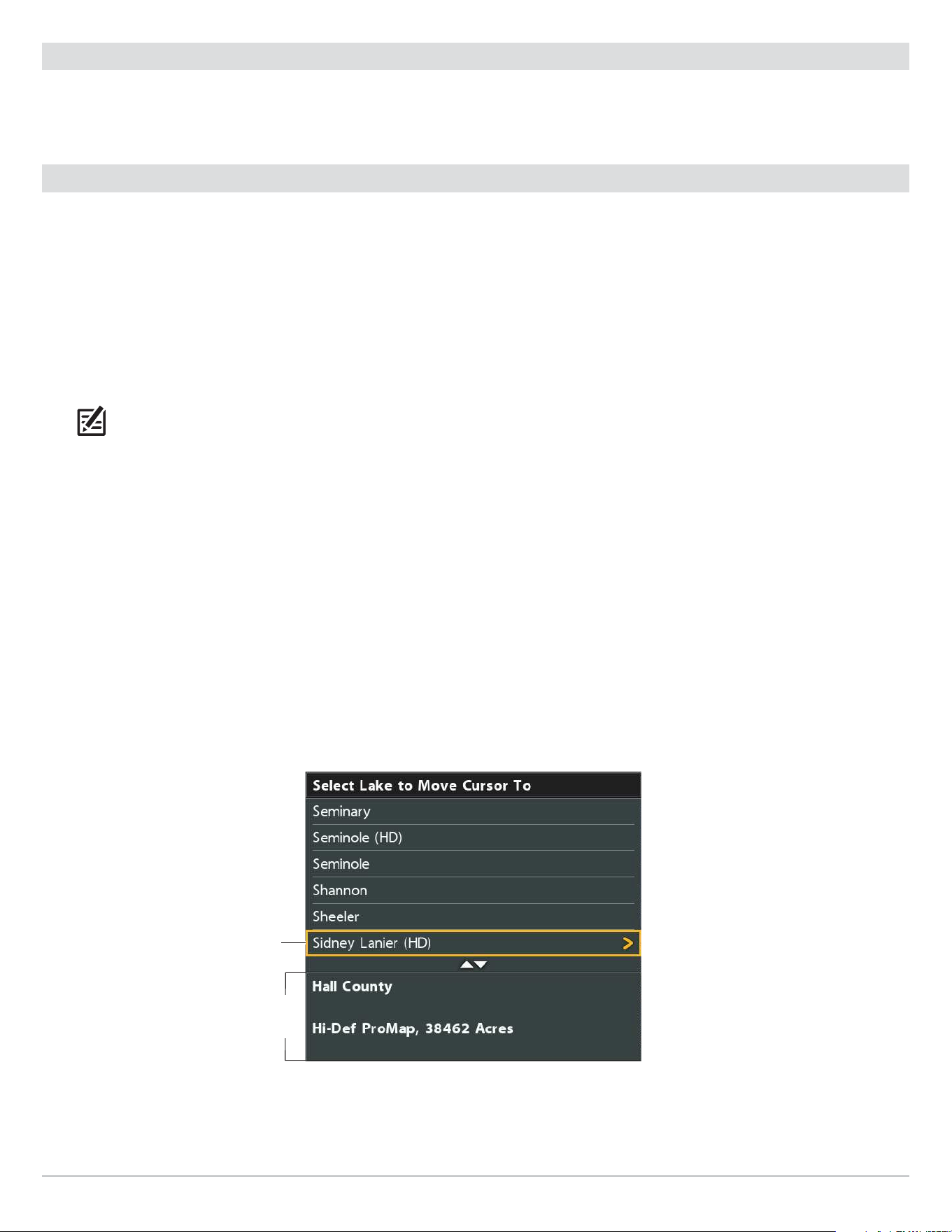
177
Search
Search for Contour Depth
1. Use the Cursor Control key to move the cursor to a contour on the chart.
2. Press the CHECK/INFO key.
Search for a Lake
Use this menu to display a lake other than your current location.
The lake map displayed on the Chart View is based on the GPS latitude/
longitude position and the Humminbird LakeMaster map card installed in the control head. GPS reception is required for the correct lake to be
displayed.
The Lake List menu option allows you to display a different lake from the installed
map card.
When you select a lake, the cursor will
move to the lake so you can see it on the Chart View. Then, you can mark waypoints, press the GOTO key to start navigation toward
a waypoint, or press the CHECK/INFO key for more information.
No GPS Reception: If you don’t have a GPS Fix, you can view the lake in Simulator mode. When you power on the control head, press the
MENU key. Select Simulator from the Start-Up Options Menu. You can mark waypoints and routes and save them in Simulator mode.
NOTE: A Humminbird LakeMaster map card must be installed to enable this feature.
Search for a Lake
1. Main Menu: Press the MENU key twice. Select the HB Chart tab.
2. Select Lake List.
3. Press the RIGHT Cursor key.
Sort By: Select the Sort By field, and press the RIGHT or LEFT Cursor keys to select a sort option for the list. You can sort
alphabetically, identify the high-definition lakes (Hi-Def) on your card, etc.
Scroll: Press the UP or DOWN Cursor keys to scroll through the list. As each lake is highlighted, you can view information about
the lake in the box displayed on the screen.
Cursor To: Select a lake on the
list. Press
the RIGHT Cursor key.
Selecting a Lake to Display
selected lake
information
about the
selected lake

178
Manage your Navigation Data
Manage your Navigation Data
Your control head allows you to start navigation or edit your navigation data from the Chart View. You can also start navigation or
edit navigation data from the Waypoint Management dialog box. The instructions in this section apply to the Waypoint Management
dialog box.
Overview
Open the Waypoint Management Dialog Box
1. Main Menu: Press the MENU key twice. Select the Nav tab.
2. Select Waypoints, Routes, Tracks.
3. Press the RIGHT Cursor key.
Sort
You can sort your saved navigation data alphabetically or by newest/oldest date, distance, or icon.
1. Press the EXIT key.
2. Select Sort By.
3. Press the RIGHT or LEFT Cursor keys to select a sort setting.
Select a File
Use these instructions to select an individual waypoint, route, track, or group. Then, use the submenu to apply settings or actions
to the selected file.
1. Press the DOWN or UP Cursor keys to select a waypoint, route, track, or group.
2. Open the Submenu: Press the RIGHT Cursor key.
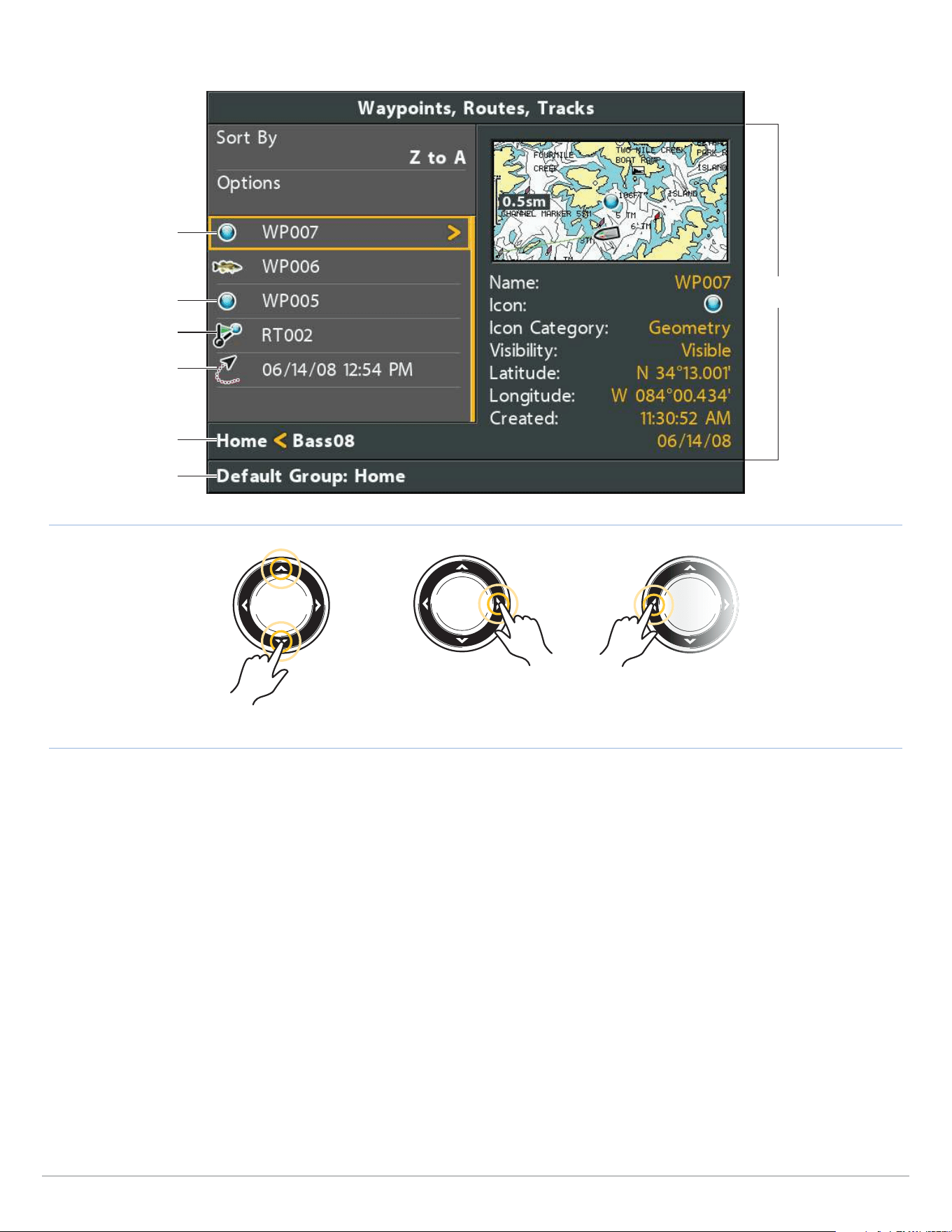
179
Manage your Navigation Data
Open a Menu Go BackScroll through the List
Selecting Files in the Waypoint Management Dialog Box (Waypoints, Routes, Tracks)
Directory: Bass08 is
the selected group
information and
instructions
selected file
(highlighted in yellow)
waypoint
route
track
selected file
preview
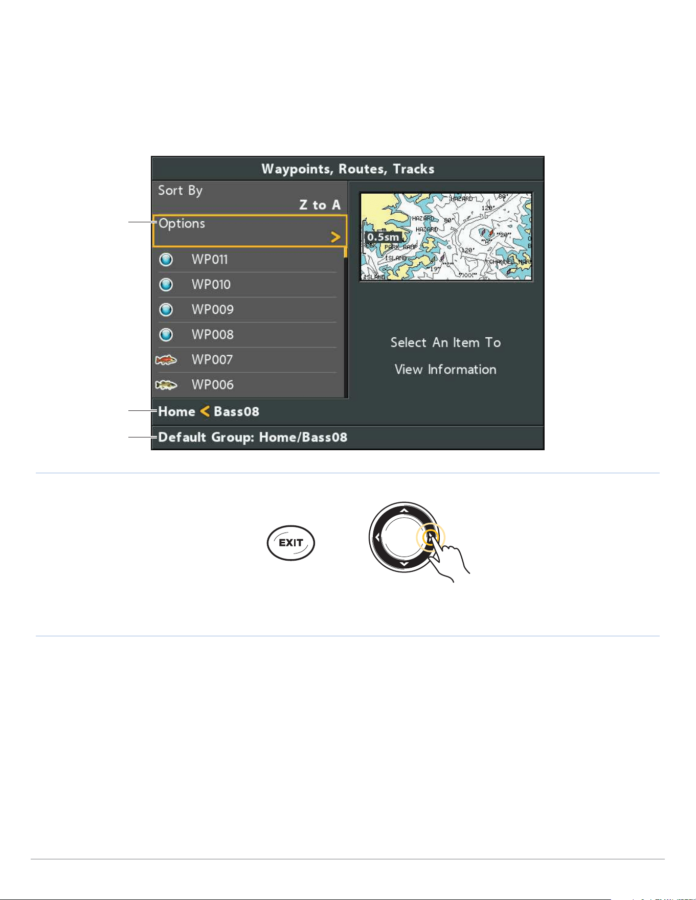
180
Manage your Navigation Data
Jump to the Top
The Options menu, and other important actions, are located at the top of the Waypoint Management dialog box. Use these
instructions to quickly select Options or jump to the top.
1. Press the EXIT key.
Selecting Options (Jump to the Top)
Directory: Bass08 is
the selected group
information
Options
Jump to the Top Open a Menu

181
Manage your Navigation Data
Manage Waypoints
When you press the MARK key and create a new waypoint, an alphanumeric name (beginning with WP) is assigned to the waypoint.
ICE HELIX CHIRP models also use alphanumeric names, but they begin with IC. You can use the Waypoint Management dialog box
to edit the saved waypoint or create a new waypoint. You can also select a waypoint icon and category for all new waypoints. .
Open the Waypoint Submenu
1. Select a waypoint from the Waypoint Management dialog box. Press the RIGHT Cursor key.
2. Select one of the following menu options:
Edit Opens the Edit Waypoint menu. See Edit a Saved Waypoint for details.
Delete
Deletes the waypoint. To remove the waypoint from the group, choose Selected. To delete the
waypoint from all groups, choose All Instances. See Delete a Waypoint for details.
Duplicate Creates a copy of the waypoint and adds it to a new group or route (see Search and Organize).
Save As
Creates a new waypoint (based on the selected waypoint) and opens a menu so you can
change the new waypoint’s name. See Search and Organize for details.
Move Moves the waypoint from the selected group to a different group (see Search and Organize).
Cursor To
Moves the cursor to the selected waypoint in the Chart View (see Navigation Overview:
Waypoints).
Go To Starts navigation to the selected waypoint (see Navigation Overview: Waypoints).
Target
Displays a target on the selected waypoint in the Chart View (see Navigation Overview:
Waypoints).
Grid
Displays a grid on the selected waypoint in the Chart View (see Navigation Overview:
Waypoints).
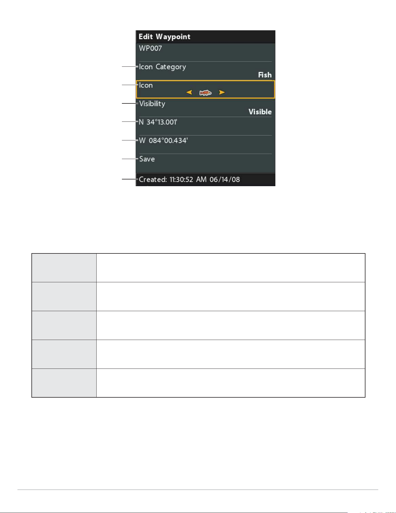
182
Manage your Navigation Data
Editing a Waypoint
icon category
changing the icon
waypoint information
save
visibility
longitude
latitude
Edit a Saved Waypoint
1. Select a waypoint. Press the RIGHT Cursor key.
2. Select Edit. Press the RIGHT Cursor key.
3. Use the Cursor Control key to edit the available fields.
Name
Select the file name, and press the RIGHT Cursor key. See the illustration Changing the
Waypoint Name.
Icon Category
Select All to view all available icons. (All, Geometry, Alerts, Supplies, Navigation, Recreation,
Fish, Environment)
Icon The available icons are determined by the category selected in Icon Category.
Visibility To show the waypoint icon on the Chart View, select Visible. To hide it, select Hidden.
Latitude
Longitude
To move from space to space, press the RIGHT or LEFT Cursor keys. To change the letter or
number, press the UP or DOWN Cursor keys.
4. Save: Select Save. Press the RIGHT Cursor key.
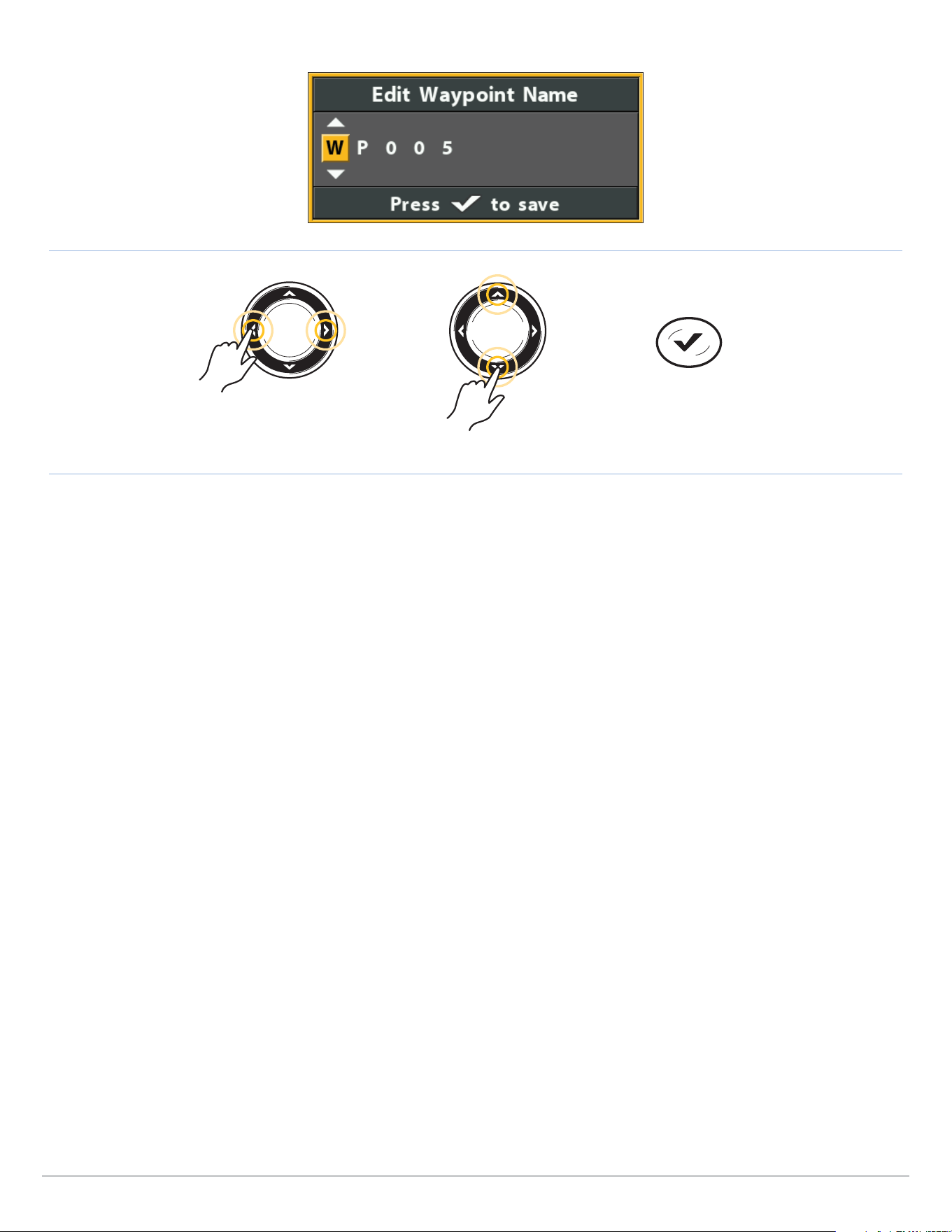
183
Manage your Navigation Data
Changing the Waypoint Name
Move from Space to Space Select a Letter, Number, or Symbol
Save
Create a New Waypoint
Use the following instructions to create a new waypoint and add your own settings. To mark a waypoint in Chart View, see Navigation
Overview: Waypoints.
1. Open a Group or Route: Select a group or route (where you want to save the new waypoint). Press the RIGHT Cursor key.
Home is the highest level group, or the main directory, in the Waypoint Management dialog box.
2. Select Open. Press the RIGHT Cursor key.
3. Select Options > New > New Waypoint.
4. Create New Waypoint: Use the Cursor Control key to set the available fields. See Edit a Saved Waypoint for details.
5. Save: Select Save. Press the RIGHT Cursor key.
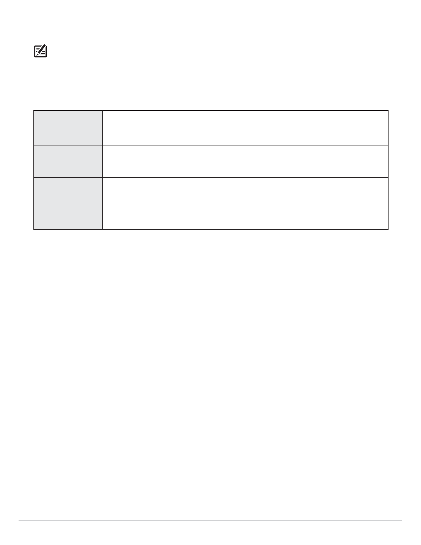
184
Manage your Navigation Data
Set the Waypoint Icon Default
Use the following instructions to set the waypoint icon category and the waypoint icon for all new waypoints.
NOTE: If the Waypoint Management dialog box is open, press the EXIT key to close the dialog box, and proceed with the following
instructions.
1. Main Menu: Press the MENU key twice. Select the Nav tab.
2. Select Waypoint Settings. Press the RIGHT Cursor key.
3. Use the Cursor Control key to set your new waypoint preferences.
Icon Category
Select All to view all available icons. (All, Geometry, Alerts, Supplies, Navigation, Recreation,
Fish, Environment)
Default Waypoint
Icon
The available icons are determined by the category selected in Icon Category.
New Waypoint
Icon
Default: When you mark a waypoint, the waypoint will be marked using the settings.
Select: Each time you mark a waypoint, you will be prompted to change the waypoint icon and
category. To accept the current settings, press the MARK key again. See Waypoints: Mark and
Edit Waypoints (on-the-go) in the Navigation section.
4. Save: Select Save. Press the RIGHT Cursor key.
Delete a Waypoint
1. Select a waypoint. Press the RIGHT Cursor key.
2. Select Delete. Press the RIGHT Cursor key.
3. To remove the waypoint from the group, choose Selected.
To delete the waypoint from all groups, choose All Instances.
4. Follow the on-screen prompts to delete the waypoint.

185
Manage Routes
Manage Routes
You can edit your saved routes, and you can also create new routes from scratch using your saved waypoints. Route names are
alphanumeric and begin with RT.
Open the Route Submenu
1. Select a route from the Waypoint Management dialog box. Press the RIGHT Cursor key.
2. Select one of the following menu options:
Open
Displays the saved waypoints in the route. You can change the waypoint order from this menu
(see Change the Waypoint Order in a Route).
Travel Starts navigation on the selected route in forward or reverse (see Travel a Saved Route).
Add/Remove
Copies waypoints into the route or deletes waypoints from the route. See Add Waypoints to
a Route and Delete a Waypoint from a Route.
Edit Opens the Edit Route menu. See Edit a Saved Route for details.
Delete
Deletes the route. To delete the route from the selected group, choose Selected. To delete the
route from all groups, choose All Instances. See Delete a Route for details.
Duplicate Creates a copy of the route and adds it to a new group (see Search and Organize).
Save As
Creates a new route (based on the selected route) and opens a dialog box so you can change
the new route’s name (see Search and Organize).
Move Moves the route from the selected group to a different group (see Search and Organize).
Info
Opens the Route Info box and displays the waypoints in the route. To change the waypoints
in a route, see Add Waypoints to a Route and Delete a Waypoint from a Route.
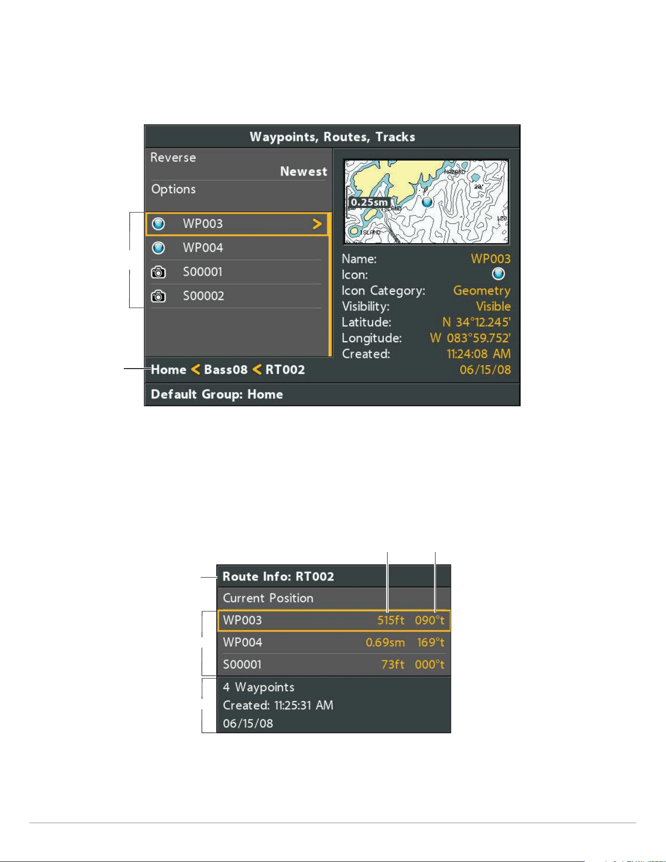
186
Manage Routes
Open a Saved Route
1. Select a route. Press the RIGHT Cursor key.
2. Select Open. Press the RIGHT Cursor key.
Opening a Saved Route
Directory: RT002 is
the selected route
waypoint order
(first to last)
Review Route Distance Information
Use the instructions in this section to open a saved route and review the distance and bearing from each waypoint to the next.
1. Select a route. Press the RIGHT Cursor key.
2. Select Info. Press the RIGHT Cursor key.
Reviewing Route Information
route name
distance bearing
waypoints
route summary
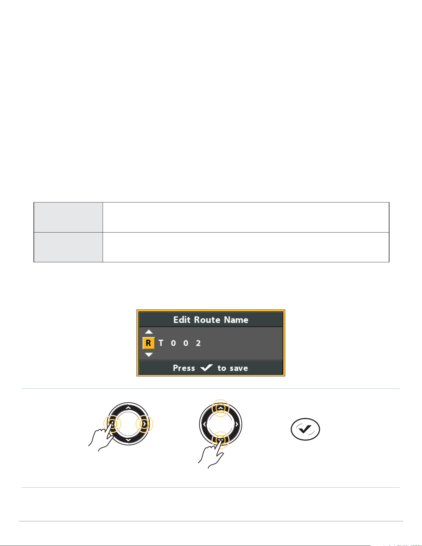
187
Manage Routes
Travel a Saved Route
1. Select a route. Press the RIGHT Cursor key.
2. Select Travel. Press the RIGHT Cursor key.
3. Select Forward or Reverse. Press the RIGHT Cursor key.
Navigation begins immediately. The Waypoint Management dialog box will close so you can see the route on the Chart View.
Edit a Saved Route
You can customize a route name, add or remove waypoints, and change the travel order for navigation.
To add waypoints to the route, or delete waypoints from the route, see Add Waypoints to a Route and Delete a Waypoint from a
Route.
To change the travel order in a route, see Change the Waypoint Order in a Route.
1. Select a route. Press the RIGHT Cursor key.
2. Select Edit. Press the RIGHT Cursor key.
3. Use the Cursor Control key to edit the available fields.
Name
Select the file name, and press the RIGHT Cursor key. See the illustration Changing the Route
Name.
Visibility To show the route on the Chart View, select Visible. To hide it, select Hidden.
4. Save: Select Save. Press the RIGHT Cursor key.
Changing the Route Name
Move from Space to Space Select a Letter, Number, or Symbol
Save
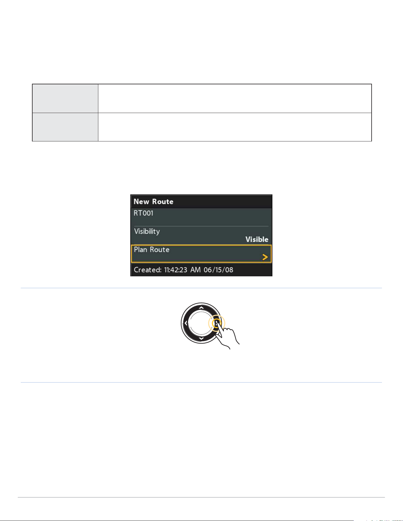
188
Manage Routes
Create a New Route
1. Open a Group: Select a group (where you want to save the new route). Press the RIGHT Cursor key.
Home is the highest level group, or the main directory, in the Waypoint Management dialog box.
2. Select Options > New > New Route.
3. Create New Route: Use the Cursor Control key to edit the available fields.
Name
Select the item name, and press the RIGHT Cursor key. See the illustration Changing the
Route Name.
Visibility To show the route on the Chart View, select Visible. To hide it, select Hidden.
4. Plan Route: Select Plan Route. Press the RIGHT Cursor key.
The New Route menu closes so you can select waypoints to add to the route.
Selecting Plan Route
Select
5. Add Waypoints: Press the UP or DOWN Cursor keys to scroll through the available waypoints.
To add a selected waypoint to the route, press the RIGHT Cursor key.
Repeat as needed. See the illustration Adding Waypoints to a Route.
6. Save: Press the EXIT key to select Save. Press the RIGHT Cursor key.
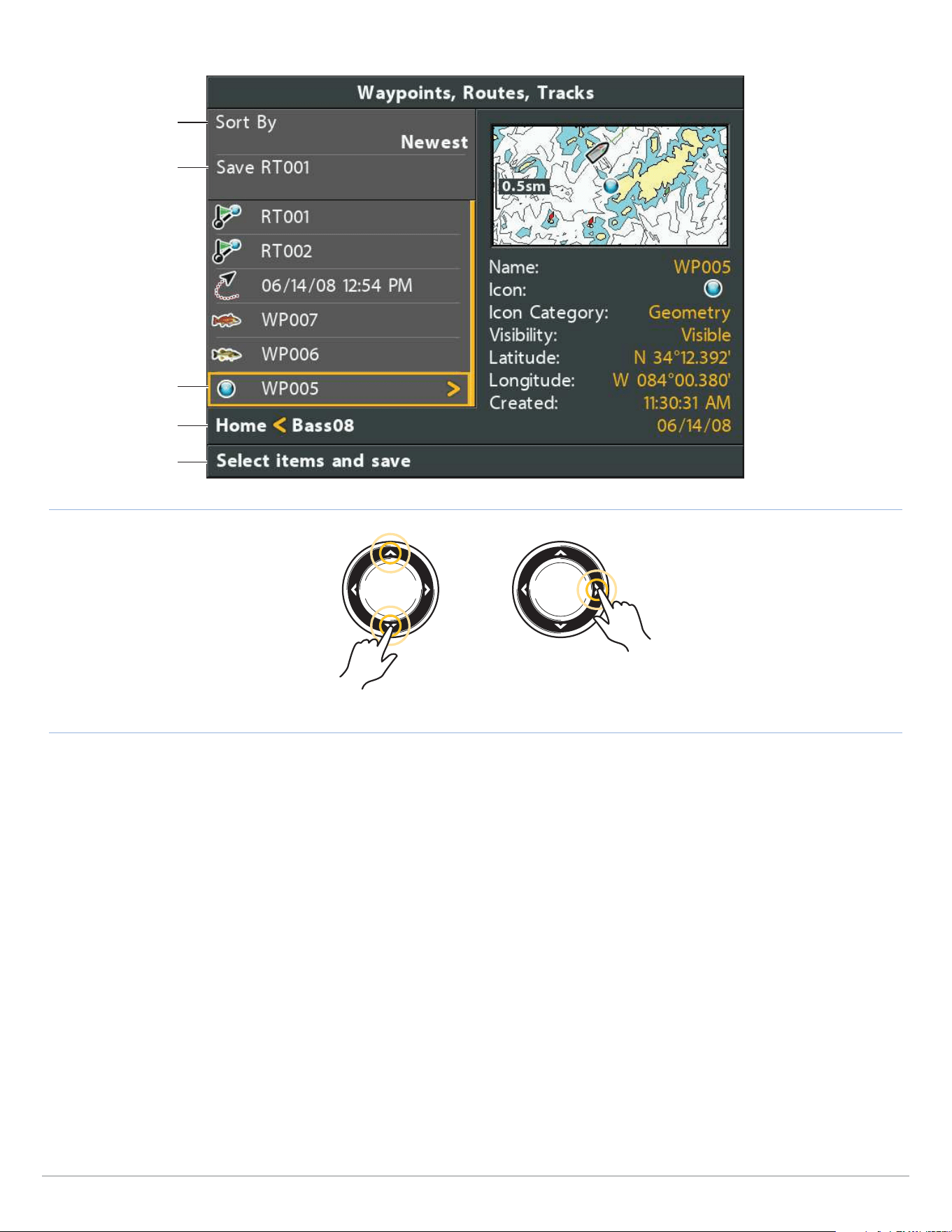
189
Manage Routes
Adding Waypoints to a Route
Directory: Bass08 is
the selected group
instructions
sort files
Scroll through the List Select
next steps
selected waypoint
(highlighted in yellow)
Add Waypoints to a Route
When you add a waypoint to a route, it is a copy. If you make changes to the copy, the changes will be made to all copies.
1. Select a route. Press the RIGHT Cursor key.
2. Select Add/Remove. Press the RIGHT Cursor key.
The menu will close.
3. Press the UP or DOWN Cursor keys to choose a waypoint. Press the RIGHT Cursor key to add it to the route.
4. Save: Press the EXIT key to select Save. Press the RIGHT Cursor key.

190
Manage Routes
Delete a Waypoint from a Route
1. Select a route. Press the RIGHT Cursor key.
2. Select Open. Press the RIGHT Cursor key.
3. Select a waypoint in the route. Press the RIGHT Cursor key.
4. Select Delete. Press the RIGHT Cursor key.
5. To remove the waypoint from the group, choose Selected.
To delete the waypoint from all groups, choose All Instances.
6. Follow the on-screen prompts to delete the waypoint.
Change the Waypoint Order in a Route
1. Select a route. Press the RIGHT Cursor key.
2. Select Open. Press the RIGHT Cursor key.
3a. Select Reverse, and press the RIGHT Cursor key. This will quickly reverse the order of the route.
OR
3b. Choose a Waypoint in the route, and press the RIGHT Cursor key.
Select Reorder, and press the RIGHT Cursor key.
To move the waypoint up or down in the route order, press the UP or DOWN Cursor keys.
See the illustration Changing the Route Order (Moving a Waypoint).
4. Press the EXIT key to select Save.
Press the RIGHT Cursor key.
Delete a Route
1. Select a route. Press the RIGHT Cursor key.
2. Select Delete. Press the RIGHT Cursor key.
3. To remove the route from the group, choose Selected.
To delete the route from all groups, choose All Instances.
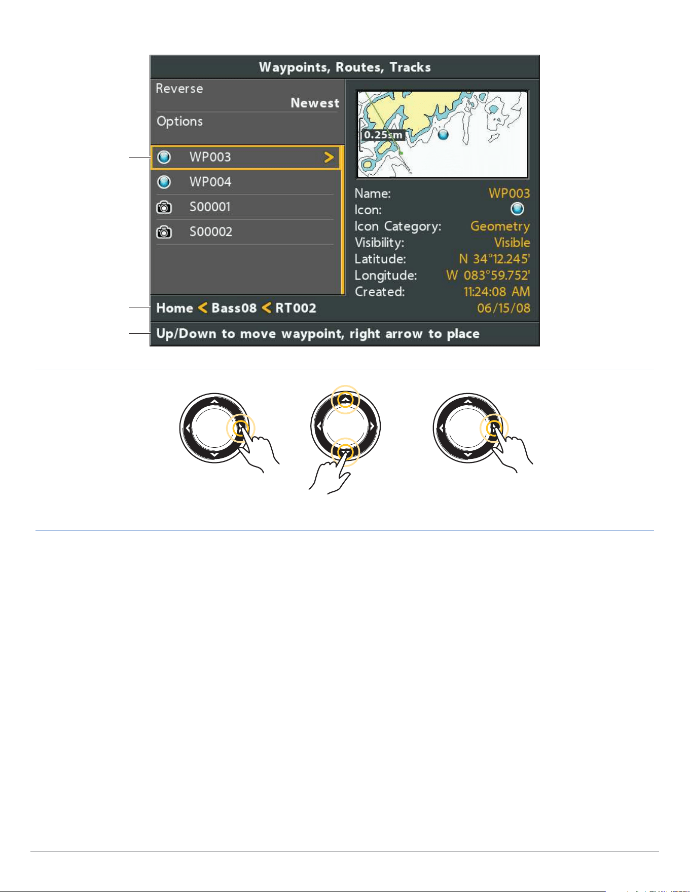
191
Manage Routes
Changing the Route Order (Moving a Waypoint)
Directory: RT002 is
the selected route
instructions
move a waypoint
up or down in the
route order
Select the Waypoint Move the Waypoint Up or Down Confirm the New Location
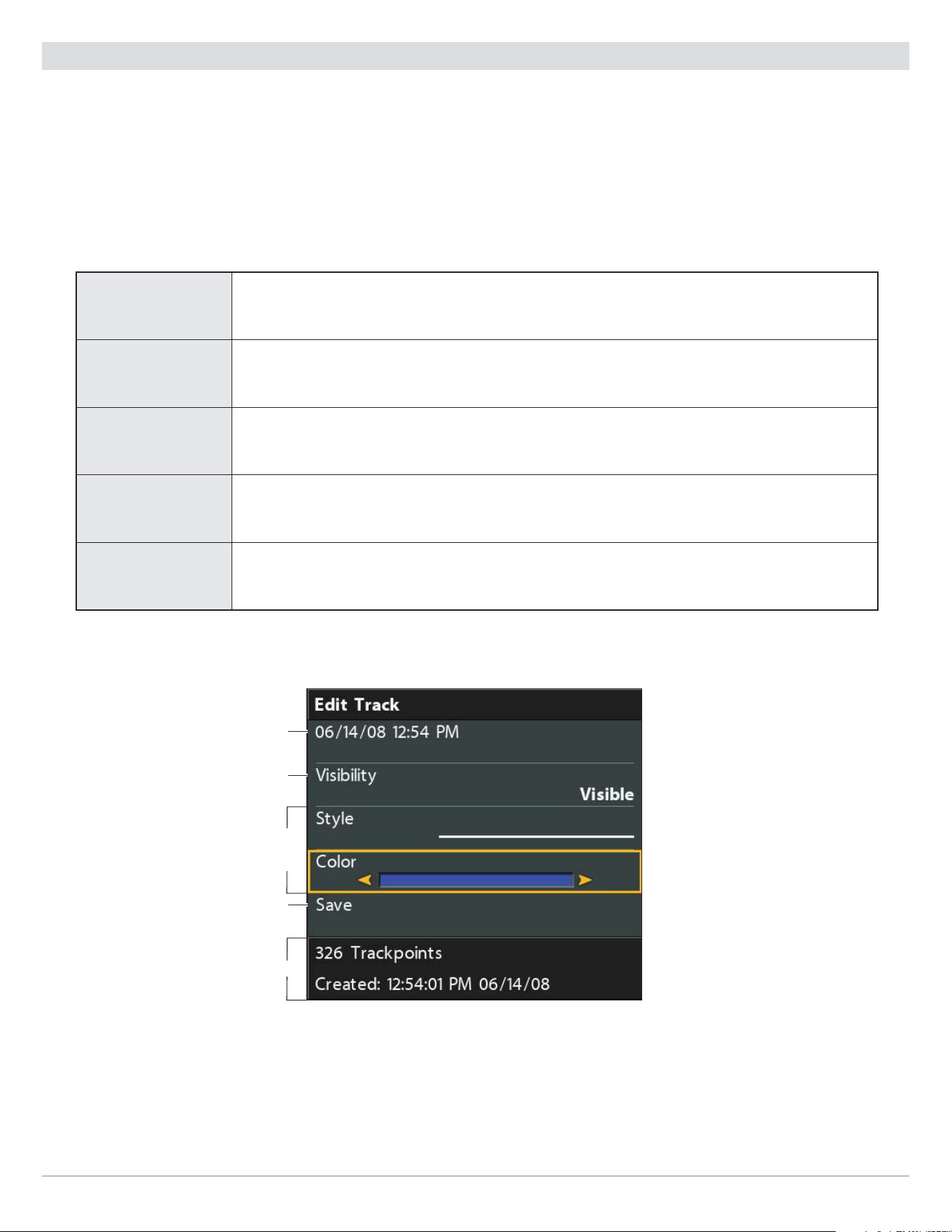
192
Manage Tracks
Manage Tracks
Save and edit your tracks with the Waypoint Management dialog box. Track names are saved with a date and time stamp. The
Tracks submenu allows you to edit the track name, appearance, and the track visibility. You can also move tracks from one group
to another group.
Open the Track Submenu
1. Select a track from the Waypoint Management dialog box. Press the RIGHT Cursor key.
2. Select one of the following menu options:
Edit Opens the Edit Track menu. See Edit a Saved Track for details.
Delete
Deletes the track. To delete the track from the selected group, choose Selected. To delete the
track from all groups, choose All Instances. See Delete a Saved Track for details.
Duplicate Creates a copy of the track and adds it to a new group (see Search and Organize).
Save As
Creates a new track (based on the selected track) and opens a menu so you can change the
new track’s name (see Search and Organize).
Move Moves the track from the selected group to a different group (see Search and Organize).
Editing a Track
save
track name
hidden or visible
track summary
To display the color
options, select
a line style.

193
Manage Tracks
Edit a Saved Track
Use the following instructions to edit a saved track. To edit the current track, see Navigation Overview: Tracks.
1. Select a track. Press the RIGHT Cursor key.
2. Select Edit. Press the RIGHT Cursor key.
3. Use the Cursor Control key to edit the available fields.
Name
Select the file name, and press the RIGHT Cursor key.
To move from space to space, press the RIGHT or LEFT Cursor keys. To change the letter or
number, press the UP or DOWN Cursor keys.
Visibility To show the icon on the Chart View, select Visible. To hide it, select Hidden.
Style Select a line style.
Color Select a color. The Color field is available if you’ve selected a solid line in the Style field.
4. Save: Select Save. Press the RIGHT Cursor key.
Delete a Saved Track
1. Select a track. Press the RIGHT Cursor key.
2. Select Delete. Press the RIGHT Cursor key.
3. To remove the track from the group, choose Selected.
To delete the track from all groups, choose All Instances.
194
Manage Groups
Manage Groups
Use groups to organize your waypoints, routes, and tracks in one set. Some anglers prefer to group their navigation items by trip,
fish-type, body of water, or time of day. New group names are alphanumeric and begin with GP, and you can edit the name.
NOTE: Groups and sub-groups use storage. The storage limit of your waypoints and routes may vary due to the complexity of your
Waypoint Management directory.
Open the Group Submenu
1. Select a group from the Waypoint Management dialog box. Press the RIGHT Cursor key.
2. Select one of the following menu options:
Open Displays the saved waypoints, routes, and tracks in the group.
Add/Remove
Copies waypoints, routes, and tracks into the group or deletes files from the group (see Add/
Remove Navigation Items).
Edit Opens the Edit Group menu. See Edit a Group for details.
Delete Deletes the group (see Delete a Group).
Move Moves the group from one location to another (see Search and Organize).

195
Manage Groups
Set a Group as the Default Directory
To save all your new waypoints, routes, and tracks to a designated group, use the following steps:
1. Select a group. Press the RIGHT Cursor key.
2. Select Open. Press the RIGHT Cursor key.
3. Select Options > Set as Default.
Create a New Group
1. Select a Save Location: Use the Cursor Control key to choose where you want to save the new group.
Home is the highest level group, or the main directory. You can also add a subgroup to an existing group. The current group
is where the new data will be saved.
2. Select Options > New > New Group.
3. Use the Cursor Control key to set the available fields.
4. Add Items: Select Add Items, and press the RIGHT Cursor key.
The New Group dialog box will close so you can select items from the Waypoint Management dialog box. You can also leave
the group empty and add to it later.
Press the UP or DOWN Cursor keys to choose a waypoint, route, or track, and press the RIGHT Cursor key to add it to the group.
Repeat as needed. See the illustration Adding Items to a Group.
5. Save: Press the EXIT key to select Save. Press the RIGHT Cursor key.
NOTE: When you add an item to a group, it is a copy. If you make changes to the copy, the changes will be made to all copies.
For example, if you change the waypoint icon for a waypoint that is saved in more than one group, the icon will change in all the
groups where the waypoint is saved.
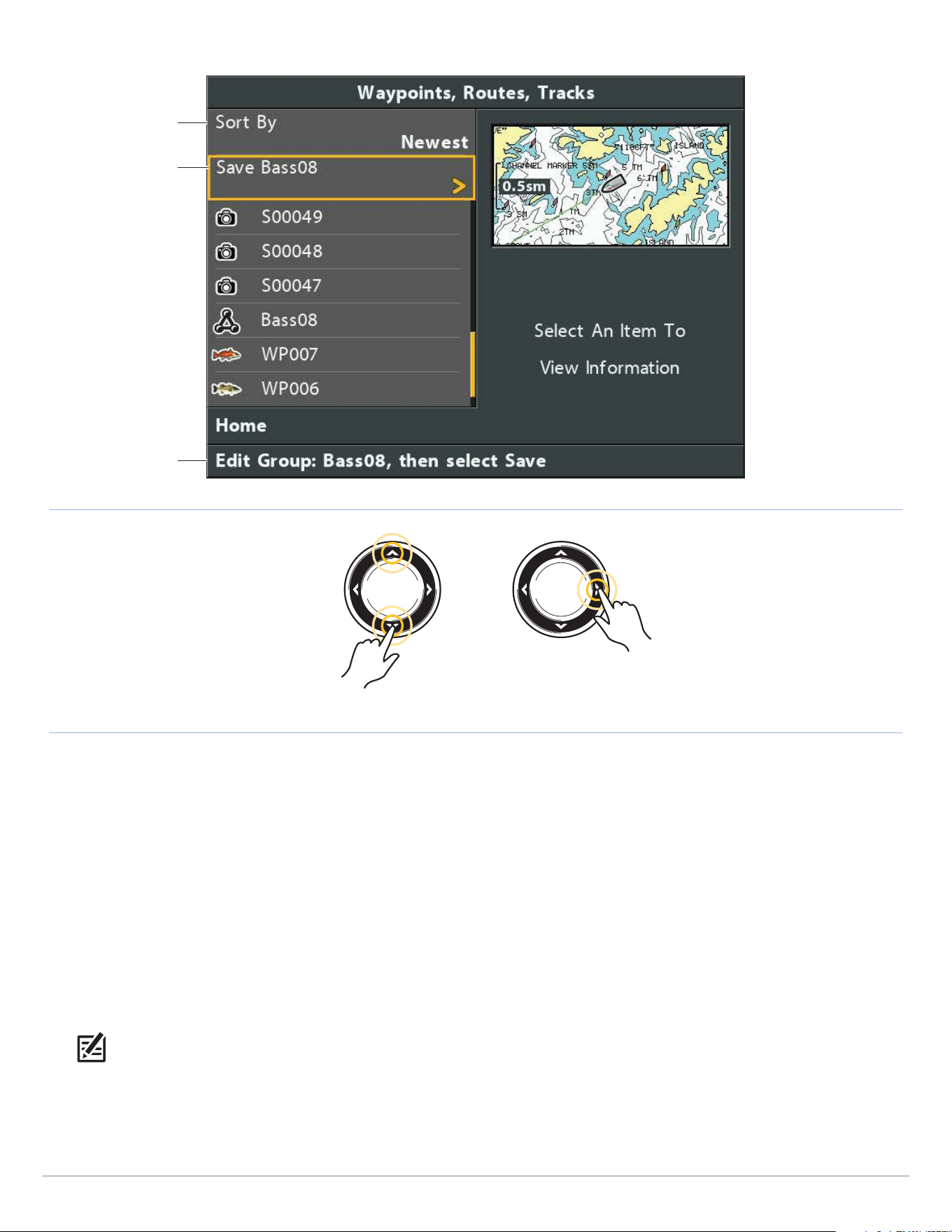
196
Manage Groups
Adding Items to a Group
instructions
sort files
Scroll Up or Down Add
next steps
Add/Remove Navigation Items
1. Select a group. Press the RIGHT Cursor key.
2. Select Add/Remove. Press the RIGHT Cursor key.
The menu will close.
3. Add: Press the UP or DOWN Cursor keys to choose a waypoint, route, or track. Press the RIGHT Cursor key to add it to the
group.
Remove: Select an item in the group. Press the RIGHT Cursor key to delete it.
4. Repeat step 3 as needed. You can add or remove items from any other group in the Waypoint Management dialog box.
5. Save: Press the EXIT key to select Save. Press the RIGHT Cursor key.
NOTE: When you add an item to a group, it is a copy. If you make changes to a copy, the changes will be made to all copies.
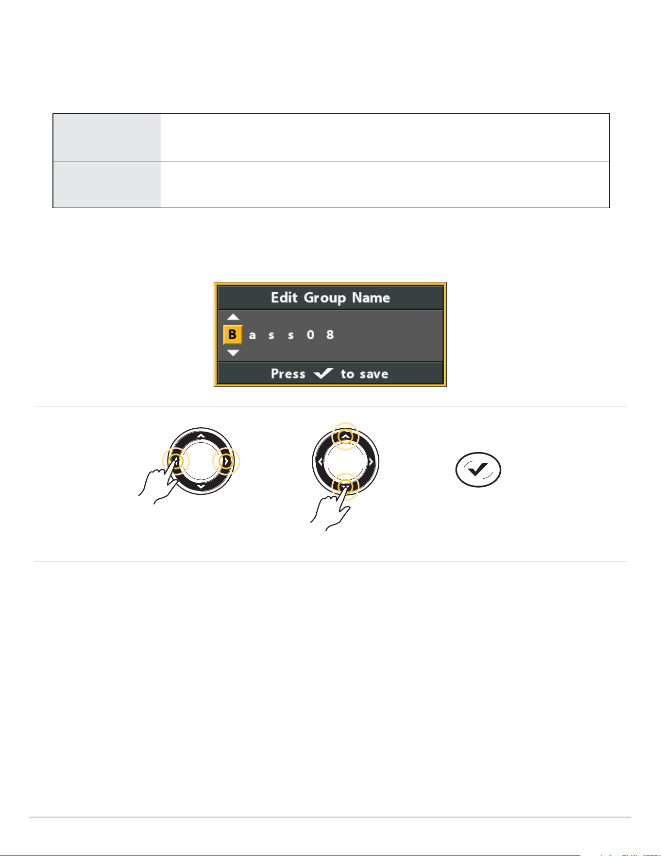
197
Manage Groups
Edit a Group
1. Select a group. Press the RIGHT Cursor key.
2. Select Edit. Press the RIGHT Cursor key.
3. Use the Cursor Control key to edit the available fields.
Name
Select the file name, and press the RIGHT Cursor key. See the illustration Changing the Group
Name.
Visibility To show the group on the Chart View, select Visible. To hide it, select Hidden.
4. Save: Select Save. Press the RIGHT Cursor key.
Changing the Group Name
Move from Space to Space Select a Letter, Number, or Symbol
Save
Delete a Group
1. Select a group. Press the RIGHT Cursor key.
2. Select Delete. Press the RIGHT Cursor key.
3. Follow the on-screen prompts to confirm.

198
Search and Organize
Search and Organize
The Waypoint Management dialog box allows you to move your waypoints, routes, and tracks into a designated group, make copies,
and search for information. You can also organize your navigation items in HumminbirdPC (see Import/Export Navigation Data),
and visit our Web site at humminbird.com for details.
Search By
Search By allows you to search the items in the Waypoint Management dialog box by Name, Distance, Date, Icon, or Icon Category.
1. Select Options. Press the RIGHT Cursor key.
2. Select Search By.
3. Select a search category. Press the RIGHT Cursor key.
4. Use the Cursor Control key to enter your search criteria in the dialog box.
5. Select Enter. Press the RIGHT Cursor key to start the search.
Duplicate or Move
Use the following instructions to move or duplicate a waypoint, route, or track. Groups can be moved, but they cannot be duplicated.
NOTE: When you make changes to a copied item, the changes are applied to all copies. To make a copy and set the item apart
from its copies, use Save As (see Create a Copy and Save as a New Item).
1. Select a waypoint, route, track, or group. Press the RIGHT Cursor key.
2. Select Move or Duplicate.
Duplicate: To create a copy of the waypoint, route, or track so that it appears in more than one group, select Duplicate.
Move: To delete the group, waypoint, route, or track from one group and transfer it to another group, select Move.
3. Use the Cursor Control key to select the destination group or route (waypoints only).
4. Press the EXIT key to select Paste here. Press the RIGHT Cursor key to confirm the change.
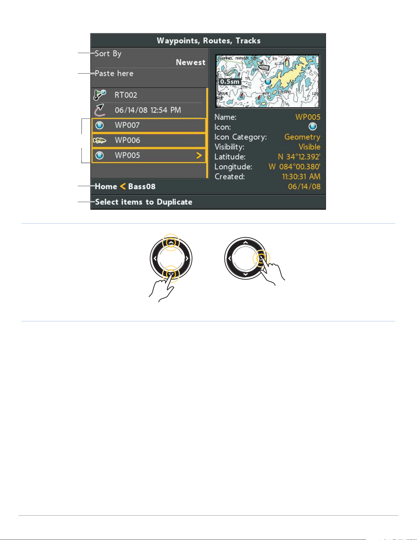
199
Search and Organize
Selecting Multiple Waypoints
Directory: Bass08 is
the selected group
instructions
sort files
Scroll Up or Down Select
next steps
selected waypoints
(highlighted in yellow)
Create a Copy and Save as a New Item
Use the instructions in this section to copy a waypoint, route, or track and save it as a separate item. The new item retains the
properties from the original, but it will not be affected by changes to the original.
1. Select a waypoint, route, or track. Press the RIGHT Cursor key.
2. Select Save As. Press the RIGHT Cursor key.
3. Use the Cursor Control key to name the new item.
4. Save: Select Save. Press the RIGHT Cursor key.

200
Manage Exporting and Deleting
Import/Export Navigation Data
Import Navigation Data
Use the following instructions to import waypoints, routes, tracks, and groups into your Humminbird control head. The control head
will import Humminbird navigation data from an installed microSD or SD card. See HELIX Control Head for compatibility details.
If the navigation data is from another source or format, it must be converted (using HumminbirdPC) before you can import it. Visit
our Web site at humminbird.com for details.
WARNING! Do NOT import navigation data from unknown sources into your Humminbird control head without first converting the
data to the correct format using HumminbirdPC. Importing corrupted data can cause the unit to malfunction, which can result
in lost navigation data.
1. Install a loaded microSD or SD card into the control head.
2. Follow the on-screen prompts to confirm or cancel the import.
Export ALL Navigation Items
Export your navigation items to an unlocked, installed microSD or SD card (separate purchase required) and then view them in
HumminbirdPC. Visit our Web site at humminbird.com for details.
1. Select Options > Select All and... > Export.
2. Follow the on-screen prompts to confirm or cancel the export.
Export Selected Navigation Items
You can also select
individual
navigation items and export them to an
unlocked, installed
microSD or SD card. See HELIX Control Head
for compatibility details.
1. From a selected group, select Options > Select Multiple and... > Export.
2. Select Items: Press the UP or DOWN Cursor keys to scroll through the waypoints, routes, and tracks. Press the RIGHT Cursor
key to select an item. Repeat as needed.
3. Confirm Export: Press the EXIT key to select Export Selected.
Press the RIGHT Cursor key. Follow the on-screen
prompts
to confirm or cancel the export.
Delete all Navigation Data and Reset
Use Format Nav Directories to delete ALL navigation data (waypoints, routes, tracks, and groups) and reset the navigation data
directory in the Waypoint Management dialog box. You may need to reset the navigation directory if you’ve imported corrupted
navigation data from an unknown source, which can cause the unit to malfunction.
CAUTION! Use this menu with caution! Contact Humminbird Technical Support before using this menu option.
NOTE: It is important to back up your control head’s data files periodically. Data files should also be saved to your PC before
restoring the unit’s defaults or updating the software. See Manage your Navigation Data:
Import/Export Navigation Data.
1. Main Menu: Press the MENU key twice. Select the Setup tab.
2. Select Format Nav Directories.
3. Press the RIGHT Cursor key.
4. Follow the on-screen prompts to confirm the deletion.

201
AutoChart Live
AutoChart Live Overview
AutoChart Live uses data from an installed GPS receiver and 2D transducer (down beam, DualBeamPLUS) to create detailed depth
maps of your favorite waters.
Map Source: Humminbird CoastMaster, Humminbird LakeMaster, or Navionics
Storage: AutoChart Live saves 8 hours of mapping data on your control head. After 8 hours of data has been collected, you
can erase the data and continue mapping, or you can purchase a ZeroLine Map Card for unlimited mapping.
ZeroLine Map Card: To purchase a ZeroLine Map Card and download the accessory guide, visit our Web site at humminbird.com.
More Information: Visit our Web site for informational videos.
Plan Your Map
Before getting started, consider the areas where you want to create a map. Review the following tips to plan your map:
General Tips
• Start with your favorite fishing hot spots. It is not recommended to record survey data of an entire lake, as it will require a lot
of time to map and might include areas you don’t want.
• Take a different route to and from each fishing spot every trip. You may discover new and interesting areas to map.
• Start a new track or recording when you start for the day. Record new data every trip to create new maps or improve existing
maps.
• Navigate the boat at a consistent speed when recording data.
• See the illustration below for instruction on how to navigate your boat while recording survey data.
Mapping a Specific Area or Object in Detail
• Navigate the boat across the area rather than alongside.
• Turn the boat where the area and/or object is out of range of the transducer beam(s).
• Try to reduce the measurement time, so as to reduce the error due to possible GPS variations.
Mapping an Entire Lake
• Follow a plan.
• Follow the maximum gradient of the sea floor (up or down).
• Keep a steady speed. For optimal performance, 0 to 8 mph is recommended.
• Turn the boat where the bottom is flat if possible.
Navigating the Boat to Record Survey Data
Navigate your boat in a
zig-zag pattern, first in
one direction and then
in the other.

202
AutoChart Live
1. Prepare the Control Head for Mapping
When you start your mapping for the day, it is important to note if the water level is higher or lower than usual. It is also important
to use your 2D transducer beams exclusively.
Set the Map Source
AutoChart Live can be used when a Humminbird CoastMaster, Humminbird LakeMaster or Navionics map card is installed and
selected as the map source. When you install a chart or map card, the map source is changed automatically to match the microSD
or SD card map source. You can also change the map source manually. If your control head has two cards installed, you can choose
which map source you want to use (HELIX 8, 9, 10, 12, 15 only).
1. Main Menu: Press the MENU key twice. Select the Chart tab.
2. Select Map Source.
3. Select the installed Humminbird CoastMaster, Humminbird LakeMaster or Navionics map card location or a built-in map.
Confirm the 2D Transducer and Turn o Additional Transducers
To record your custom map, you must have a reliable and accurate digital depth from a pinging 2D transducer. You can use your
Humminbird DualBeam PLUS transducer (83/200 kHz), Side Imaging transducer with 2D (down beam) capabilities, or a CHIRP
transducer with 2D (down beam) capabilities.
When you are recording your map, you should have only one 2D transducer pinging on your boat. If you have other 2D transducers
pinging on remote control heads, you should turn them off. Down Imaging and Side Imaging beams can operate at the same time.
You do not need to turn them off.
1. Main Menu: Press the MENU key twice. Select the Sonar tab.
2. Select Connected Transducer.
3. Confirm the transducer connected to the control head is selected.
4. If there are additional control heads on your boat with a 2D transducer, confirm that they are not pinging while you are
mapping. There should be only one 2D transducer pinging on your boat during the recording process.

203
AutoChart Live
Confirm Digital Depth and GPS Fix
1. Display a Chart View on-screen.
2. Confirm Digital Depth: Confirm the depth digital readout is displayed.
It may take a moment for depth to be displayed.
3. Confirm GPS Fix: Confirm the speed digital readout is displayed.
NOTE: Digital readouts can be displayed as an overlay, or they can be displayed in data boxes (see Views: Display Digital
Readouts).
digital depth missing digital depth detected
Confirming the Digital Depth Source Confirming the Digital Depth Source
Adjust the Water Level Oset
When you start your mapping for the day, it is important to note if the water level is higher or lower than usual. For example, if you
are mapping on a lake and know the lake is down 3 feet, set the Water Level Offset to -3.
1. Main Menu: Press the MENU key twice. Select the HB Chart tab.
2. Select Water Level Offset.
3. Use the RIGHT or LEFT Cursor keys to adjust the setting.
If the water level is higher than normal, set a positive amount.
If the water level is lower than normal, set a negative amount.
If the water level has not changed (normal), turn off Water Level Offset.

204
AutoChart Live
Display the Current Track (optional)
It is helpful to display the current track so you can see where the boat has already traveled while you’re recording the map.
1. Main Menu: Press the MENU key twice. Select the Nav tab.
2. Select Current Track. Press the RIGHT Cursor key.
3. Select Appearance. Press the RIGHT Cursor key.
4. Select Visibility. Press the RIGHT or LEFT Cursor key to select Visible.
5. Save: Select Save. Press the RIGHT Cursor key.
Start a Sonar Recording for AutoChart PC (optional)
If you are planning to use AutoChart PC, start a sonar recording before you start recording your custom map.
1. Install a microSD or SD card into the control head card slot.
See HELIX Control Head for compatibility details.
2. Press and hold the VIEW key.
3. Select System > Snapshot and Recording View.
4. Press the MENU key.
5. Select Start Recording. Press the RIGHT Cursor key.
File Name: A waypoint will also be created at the boat location, and the recording shares the same file name as the waypoint
(.SON).
Use Different Views: To use different views on the control head and continue recording, press the EXIT key.
Not Available: Taking screen snapshots and playback mode are not available during recording.
NOTE: For more information, see Manage Screen Snapshots and Recordings. Also, visit our Web site at humminbird.com to
purchase AutoChart PC and download the manual.
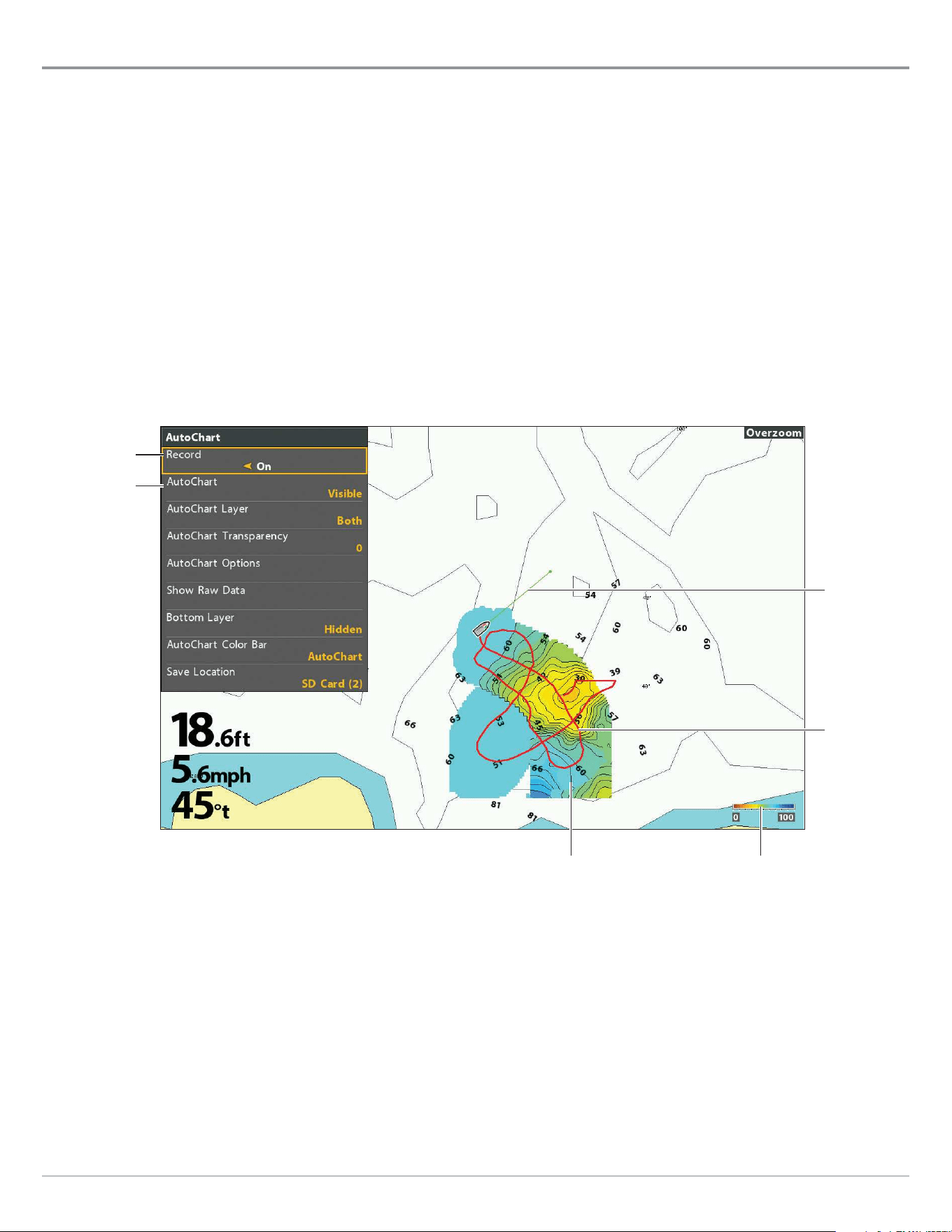
205
AutoChart Live
2. Record your Custom Map
1. Preparation: Before you start mapping for the day, confirm that the control head is set up as shown in the section Prepare
the Control Head for Mapping.
2. Chart X-Press Menu: With a Chart View displayed on-screen, press the MENU key once.
3. Select AutoChart. Press the RIGHT Cursor key.
4. Select Record.
5. Select On.
Display: Select AutoChart. Select Visible
(LakeMaster) or press the CHECK key or the RIGHT Cursor key to add a check mark
(CoastMaster)
.
Zoom In: Press the +ZOOM key to see the depth data on the Chart View.
6. Navigate your boat in a zig-zag pattern, first in one direction and then in the other. For optimal performance, maintain a
consistent speed between 0 and 8 mph. See Plan your Map for details.
heading line
(green line)
depth scale
(AutoChart Color Bar)
turn on
Record
select Visible
to display the
depth map
on the Chart
View
Starting an AutoChart Live Recording
current
track
(red line)
depth map in
progress
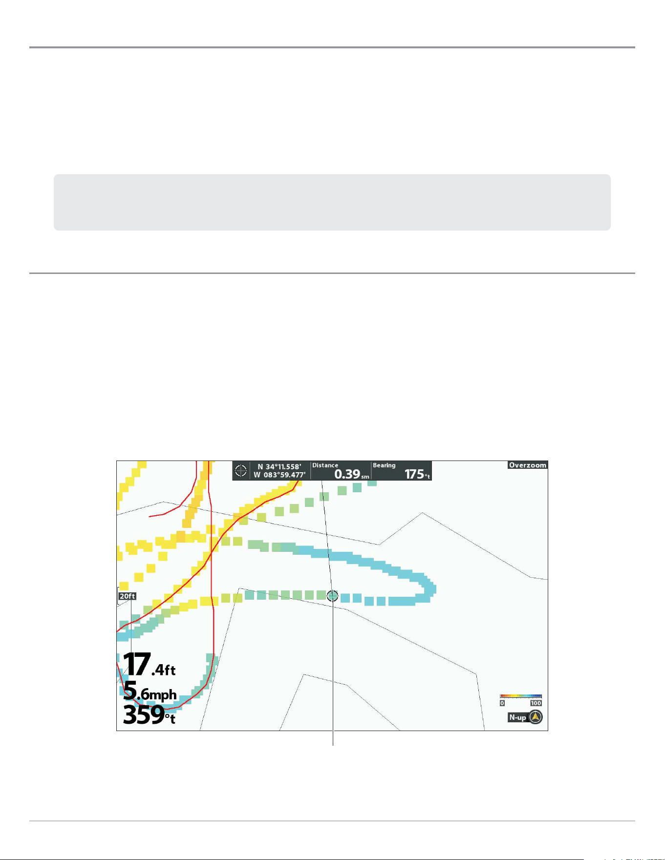
206
AutoChart Live
3. Stop Recording
Use the instructions in this section to stop recording. Your map is automatically saved to the control head (internal) or to the
ZeroLine Map Card if it is installed.
1. Chart X-Press Menu: With a Chart View displayed on-screen, press the MENU key once.
2. Select AutoChart. Press the RIGHT Cursor key.
3. Select Record.
4. Select Off.
If you do not have a ZeroLine Map Card installed, and the control head storage (8 hours) is reached, the control head
will provide a dialog box to Confirm or Clear Data. To save your map and turn off recording, select Confirm. To erase
your map and start over, select Clear Data.
Correct Data
If you see an irregularity in the data (such as lost depth), it can be deleted. Recording must be turned off while you correct the data.
1. Chart X-Press Menu: With a Chart View displayed on-screen, press the MENU key once.
2. Select AutoChart. Press the RIGHT Cursor key.
3. Select Show Raw Data. Press the RIGHT Cursor key.
4. Press the +ZOOM key to see individual data points.
5. Exit the AutoChart Menu by pressing the EXIT key three times and then move the cursor over a data point.
6. From the AutoChart menu, select Delete. Press the RIGHT Cursor key.
Selecting a Data Point
cursor selecting
a data point

207
AutoChart Live
Using AutoChart Live in Ice Fishing Mode
AutoChart Live is available on ICE HELIX control heads and All-Season control heads operating in Ice Fishing Mode (GPS units only).
AutoChart Live maps created while in Ice Fishing Mode are single snapshots rather than recordings of large areas.
NOTE: Ice Fishing Mode must be turned on to enable this feature (see Ice Fishing Overview: Turn on Ice Fishing Mode).
Capture Your Custom Map
1. Preparation: Before you capture your map, confirm that the control head is set up as shown in the section Prepare the
Control Head for Mapping.
2. With a Chart View displayed on-screen, press the MARK key.
3. Select AutoChart.
4. Press the RIGHT Cursor key.
Your map is automatically saved to the control head (internal) or to the ZeroLine Map Card if it is installed.
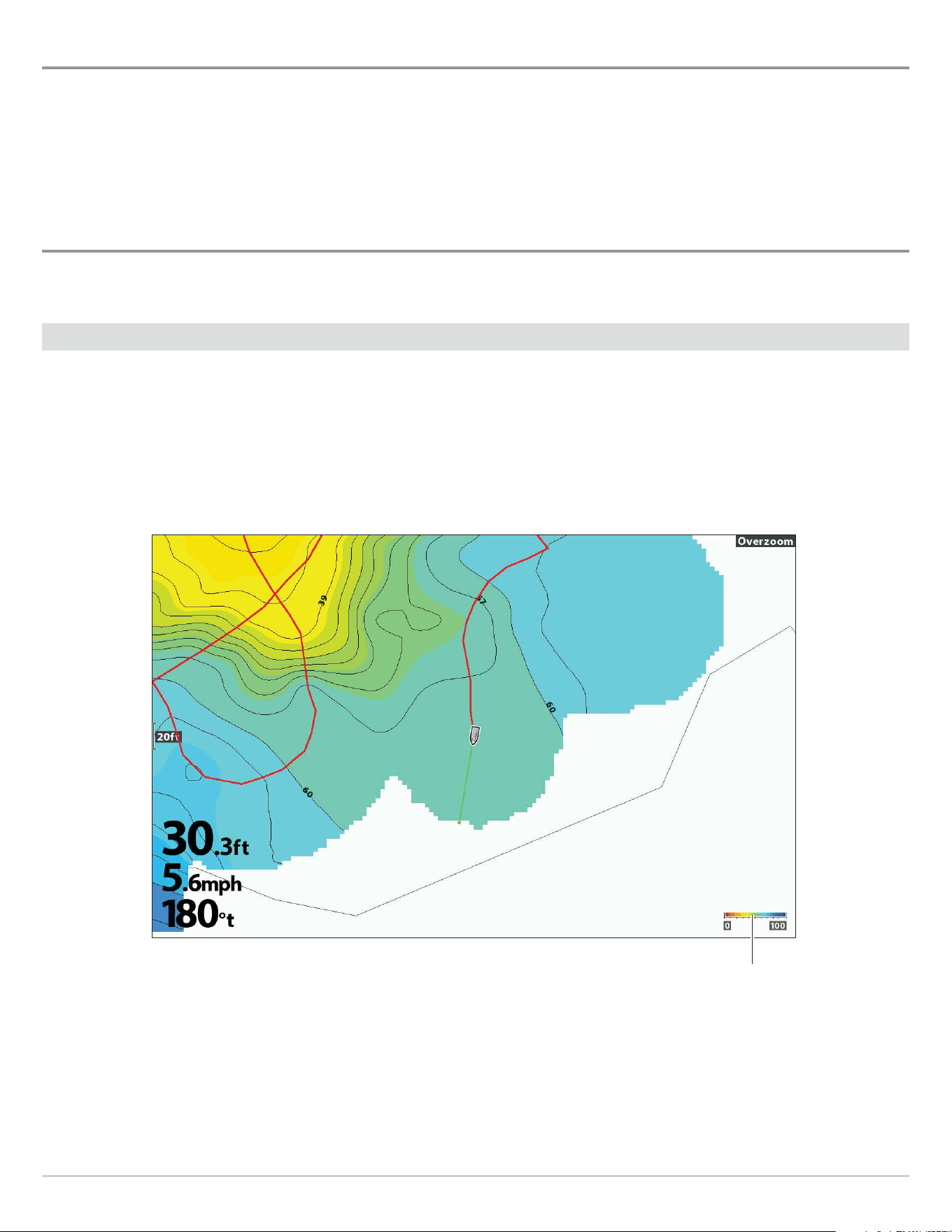
208
AutoChart Live
Open the AutoChart Menu
You will use the AutoChart menu for all settings. Some of the menu options in this section may be displayed in other parts of the
menu system so that you can access them quickly. No matter where you make the change, the control head will update the setting
across the system.
1. Chart X-Press Menu: With a Chart View displayed on-screen, press the MENU key once.
2. Select AutoChart. Press the RIGHT Cursor key.
Display the AutoChart Live Map
You can make changes to the AutoChart Live map during recording or after you’ve saved your map. You can also view bottom
hardness or vegetation data, and you can customize how the data is displayed.
Show/Hide the AutoChart Live Map
The custom map can be displayed or hidden while you are recording or after the map is saved. You can also adjust the transparency.
Show the AutoChart Live Map
1. From the AutoChart menu, select AutoChart.
2.
Select
Visible
(LakeMaster) or press the CHECK/INFO key or the RIGHT Cursor key to add a check mark (CoastMaster).
AutoChart Color Bar
set to AutoChart
Chart View with AutoChart Live Map Displayed
Hide the AutoChart Live Map
1. From the AutoChart menu, select AutoChart.
2. Select Hidden (LakeMaster) or press the C
HECK/INFO key or the RIGHT Cursor key to remove the check mark (CoastMaster)
.
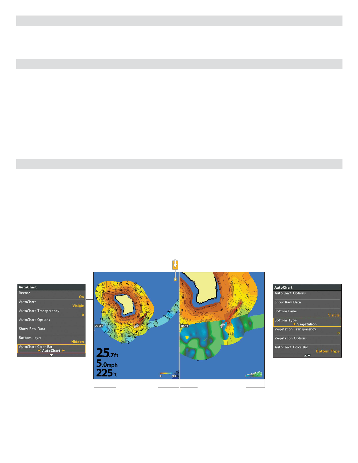
209
AutoChart Live
Adjust the Transparency
1. From the AutoChart menu, select AutoChart Transparency.
2. Press the RIGHT or LEFT Cursor keys to adjust the setting.
Display the AutoChart Color Bar
The AutoChart Color Bar allows you to display the palette icon for AutoChart or Bottom Type. See the illustrations Chart View with
AutoChart Live Map Displayed and Chart/Chart Combo View.
You can use this icon to see the selected palette and, from left to right, the AutoChart Live depth range (low to high), Bottom
Hardness range (soft to hard), or Vegetation range (soft to hard).
Show/Hide the AutoChart Color Bar
1. From the AutoChart menu, select AutoChart Color Bar.
2. Select a display bar.
Display AutoChart Live and Bottom Layer in Chart/Chart Combo View
You can also use the Chart/Chart Combo View to display AutoChart Live and Bottom Layer data at the same time. Use the X-Press
Menu to make adjustments to each pane. See Views: Combo Views for more information.
Display the Chart/Chart Combo View
1. Press and hold the VIEW key.
2. Select Chart > Chart/Chart Combo View.
Chart/Chart Combo View (Map Source: Humminbird LakeMaster)
AutoChart Menu
indicates the selected
pane (Active Pane)
AutoChart Live Map
Visible
AutoChart Live Visible
with Vegetation Bottom
Layer Displayed
AutoChart Menu
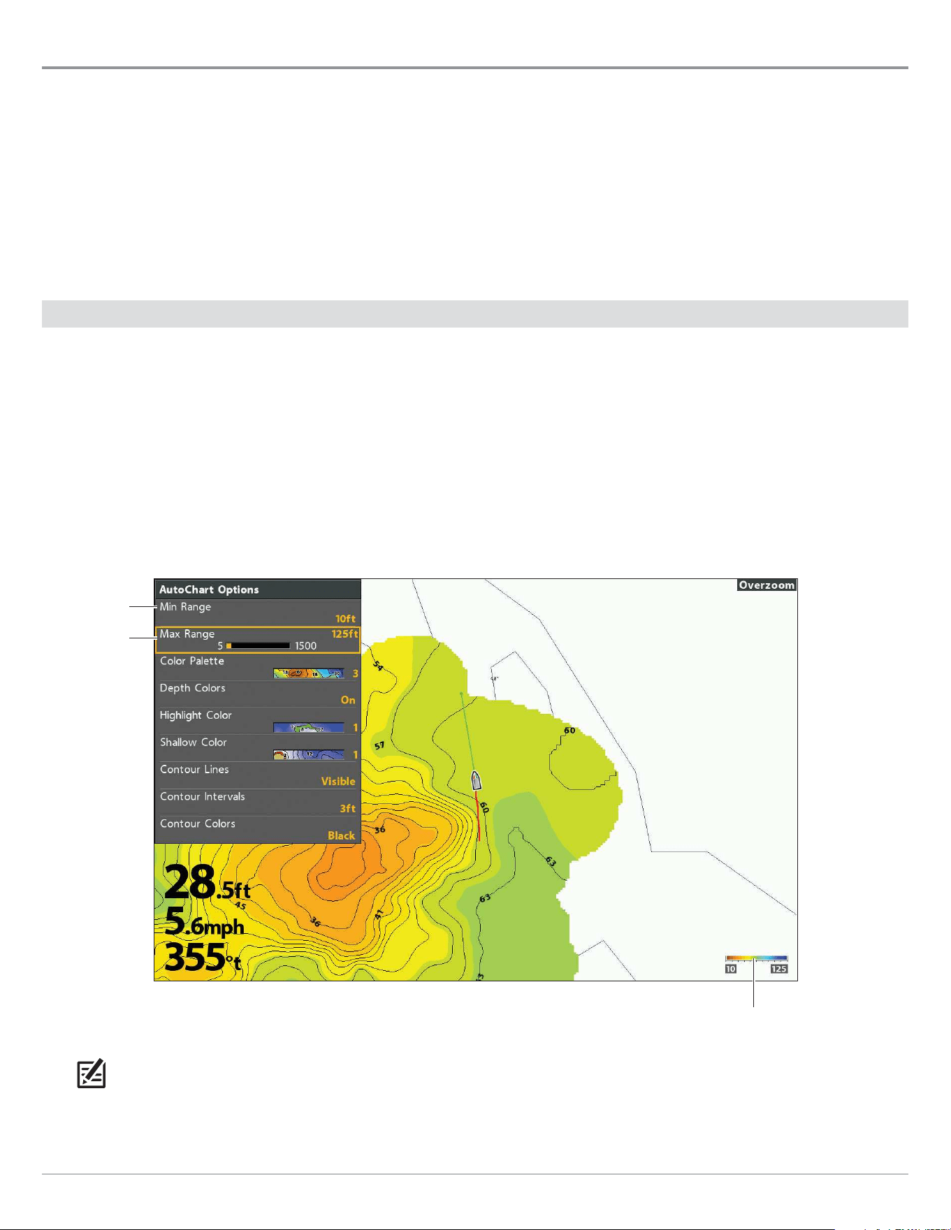
210
AutoChart Live
Customize the AutoChart Live Map Display Settings
Use the AutoChart Options menu to adjust the depth range, contour interval, and map position. You can also change the color
palette and shading.
Open the AutoChart Options Menu
You will use the AutoChart Options menu for all display settings.
1. Chart X-Press Menu: With a Chart View displayed on-screen, press the MENU key once.
2. Select AutoChart. Press the RIGHT Cursor key.
3. Select AutoChart Options. Press the RIGHT Cursor key.
Adjust the Depth Range
You can adjust the range of data shown on the chart by changing the minimum range and maximum range on the display. The
range you select affects how the depth colors are displayed. For related color or shading options, see Change the Display Colors.
1. From the AutoChart Options menu, select Min Range.
2. Press the RIGHT or LEFT Cursor keys to adjust the setting.
3. Select Max Range.
4. Press the RIGHT or LEFT Cursor keys to adjust the setting.
depth scale
(AutoChart Color Bar)
low range
high range
Adjusting the AutoChart Live Map Depth Range
NOTE: Use the AutoChart Color Bar icon see the selected palette and, from left to right, the AutoChart depth range (low to high),
Bottom Hardness range (soft to hard), or Vegetation range (soft to hard).
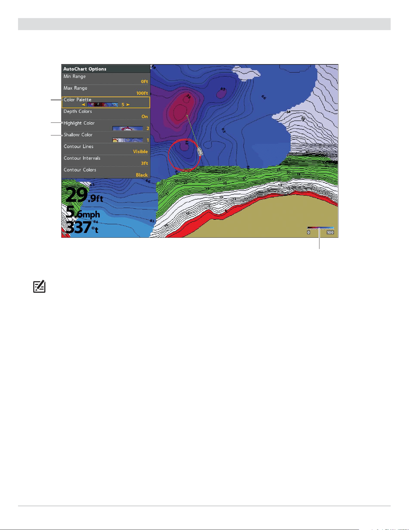
211
AutoChart Live
Change the Display Colors
Use the following instructions to change the color palette used to display the AutoChart Live map.
depth scale
(AutoChart Color Bar)
color
palette
highlight
color
Changing the AutoChart Live Map Display Colors (Map Source: Humminbird LakeMaster)
shallow color
NOTE: Use the AutoChart Color Bar icon see the selected palette and, from left to right, the AutoChart depth range (low to high),
Bottom Hardness range (soft to hard), or Vegetation range (soft to hard).

212
AutoChart Live
Show/Hide Depth Colors
Use the following instructions to show or hide the depth colors. If you hide the depth colors, the contours will be shown on the
display.
1. From the AutoChart Options menu, select Depth Colors.
2. LakeMaster Users: Select a On (visible) or Off (hidden).
CoastMaster Users:
Press the CHECK/INFO key or the RIGHT Cursor key. (check mark = visible, blank = hidden)
Change the Color Palette
The Color Palette menu changes the colors used to display the AutoChart Live map. The color range is shown in the AutoChart Color
Bar and is affected by the Min Range and Max Range settings. See Adjust the Depth Range for more information.
1. From the AutoChart Options menu, select Color Palette.
2. Select a palette.
Change the Highlight Color
If you’ve set a Depth Highlight in the HB Chart tab, and it is not easy to see with the AutoChart Live color palette you’ve selected ,
you can change the Highlight Color. See Display Humminbird LakeMaster Contour Lines and Depth Ranges or Display Humminbird
CoastMaster Contour Lines and Depth Ranges for more information.
1. From the AutoChart Options menu, select Highlight Color.
2. Select a color.
Change the Shallow Color
If you’ve set the Shallow Water Highlight in the HB Chart tab, and it is not easy to see with the AutoChart Live color palette you’ve
selected, you can change the Shallow Color. See Display Humminbird LakeMaster Contour Lines and Depth Ranges Display or
Humminbird CoastMaster Contour Lines and Depth Ranges for more information.
1. From the AutoChart Options menu, select Shallow Color.
2. Select a color.
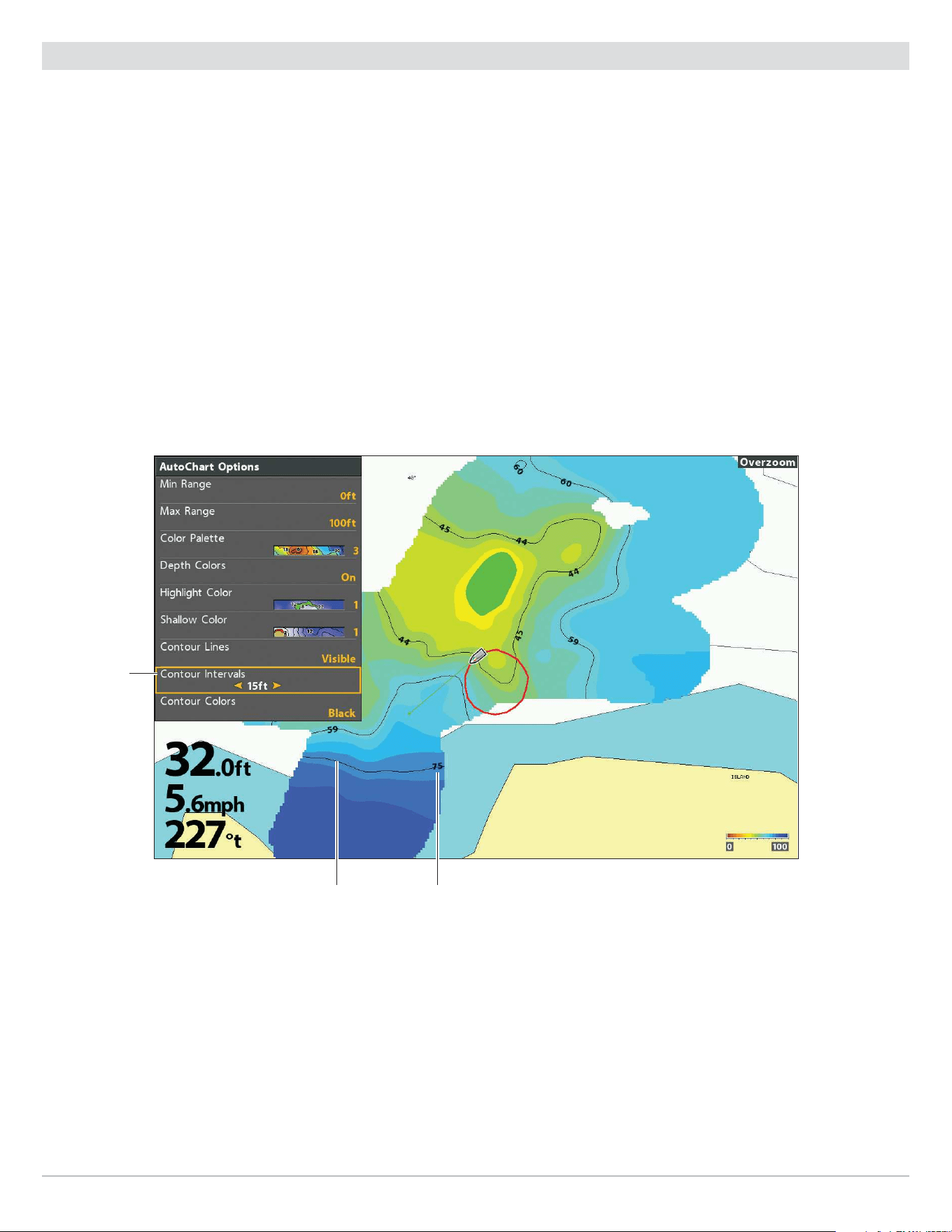
213
AutoChart Live
Display Contour Lines and Adjust the Contour Interval
You can display or hide the contour lines on the map, and you can adjust the distance between each contour line. Contour Interval
is also affected by the Water Level Offset setting.
Display the Contour Lines and Adjust the Contour Interval
1. From the AutoChart Options menu, select Contour Lines.
2.
Select
Visible
(LakeMaster) or press the CHECK/INFO key or the RIGHT Cursor key to add a check mark (CoastMaster).
3. Select Contour Intervals.
4. Press the RIGHT or LEFT Cursor keys to adjust the setting.
Change the Contour Lines Color
1. From the AutoChart Options menu, select Contour Colors.
2. Select a color.
contour line
Changing the AutoChart Live Map Display Colors (Map Source: Humminbird LakeMaster)
contour
intervals
depth label
(depth of contour)
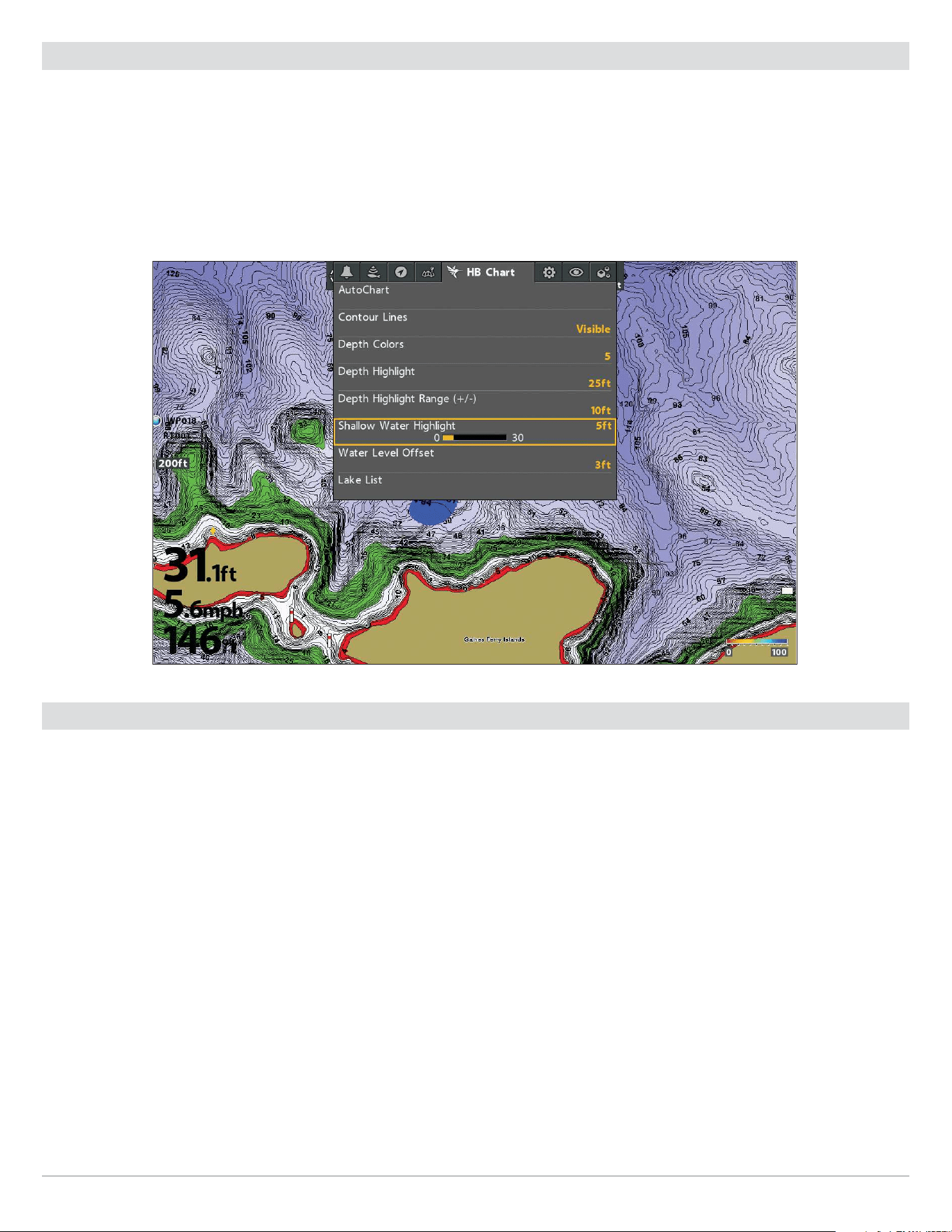
214
AutoChart Live
Add Settings with Chart Options
You can also add adjustments to your custom map using the HB Chart menu. For example, if Humminbird is set as the map source,
you can add Depth Colors, Shallow Water, etc. to your AutoChart Live map. See Display Humminbird LakeMaster Contour Lines and
Depth Ranges or Display Humminbird LakeMaster Contour Lines and Depth Ranges.
If Navionics is set as the map source, you can display Contours and Shading on your AutoChart Live map. See Customize the Chart
View for more information.
Adding Shallow Water Settings to the Map
(Map Source: Humminbird LakeMaster)
Change the Water Level Oset
When you start your mapping for the day, it is important to note if the water level is higher or lower than usual. See Prepare the
Control Head for Mapping for more information.
1. Main Menu: Press the MENU key twice. Select the HB Chart tab.
2. Select Water Level Offset.
3. Use the RIGHT or LEFT Cursor keys to adjust the setting.
If the water level is higher than normal, set a positive amount.
If the water level is lower than normal, set a negative amount.
If the water level has not changed (normal), turn off Water Level Offset.
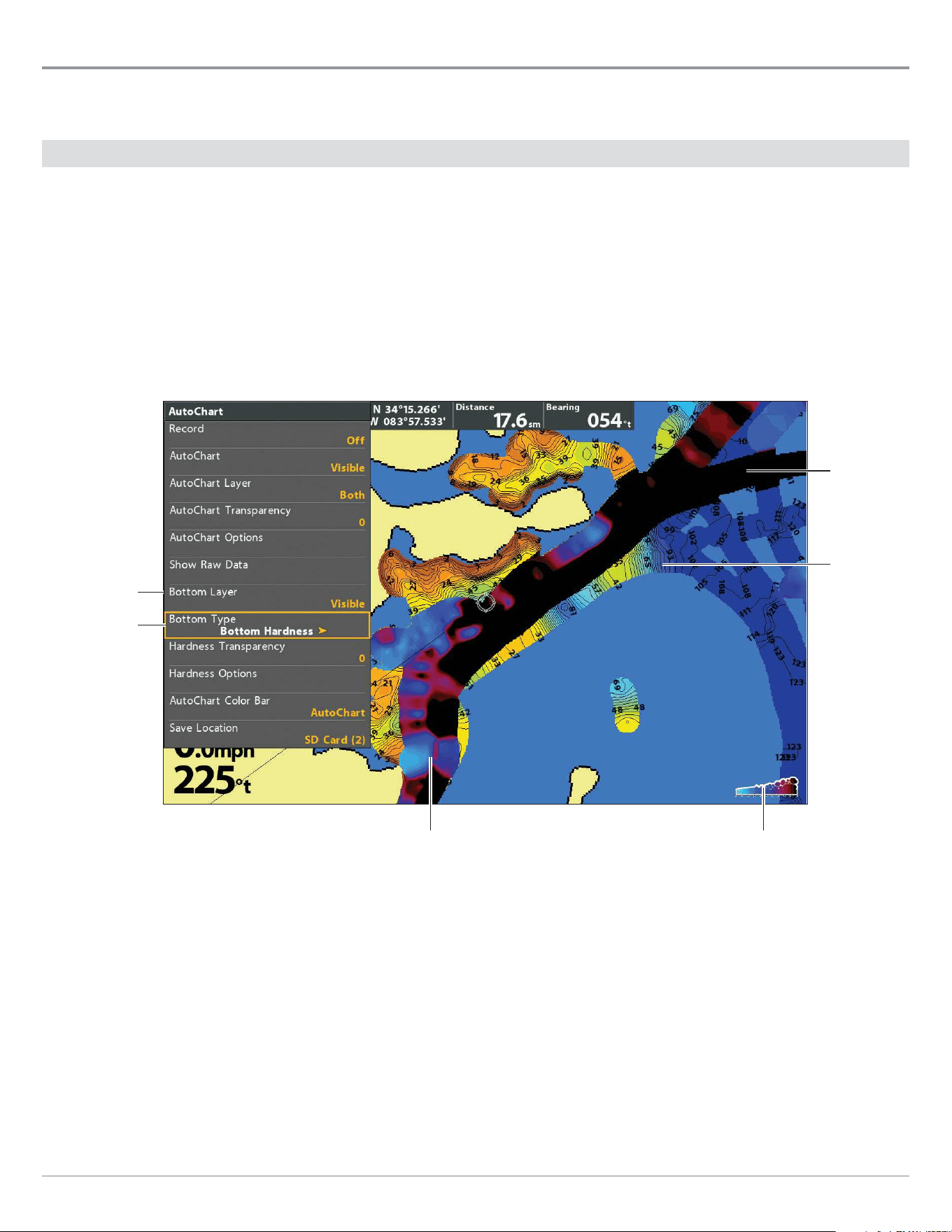
215
AutoChart Live
Customize the Bottom Hardness Display Settings
The Bottom Layer is displayed on top of the AutoChart Live map and can be displayed as bottom hardness or vegetation. Bottom
Hardness shows strong sonar returns resulting from compacted sediment, rocks, fallen trees, etc.
Show/Hide Bottom Hardness
Show Bottom Hardness
1. From the AutoChart menu, select Bottom Layer.
2.
Select
Visible
(LakeMaster) or press the CHECK/INFO key or the RIGHT Cursor key to add a check mark (CoastMaster)
.
3. Select Bottom Type.
4. Select Bottom Hardness.
AutoChart
Live Map
layer
hardness scale
(AutoChart Color Bar)
bottom
layer set
to Visible
bottom type
Displaying the Bottom Hardness Layer (Map Source: Humminbird LakeMaster)
bottom
hardness
layer
bottom
hardness layer
Hide Bottom Hardness
1. From the AutoChart menu, select Bottom Layer.
2. Select Hidden
(LakeMaster) or press the CHECK/INFO key or the RIGHT Cursor key to remove the check mark (CoastMaster)
.

216
AutoChart Live
Adjust the Gain Oset
Use Gain Offset to tune the bottom hardness display. For example, if you’re fishing a lake where most of the lake has a hard bottom,
reduce the gain so only the hardest bottom is displayed.
1. From the AutoChart menu, select Hardness Options.
Press the RIGHT Cursor key.
2. Select Gain Offset.
3. Press the RIGHT or LEFT Cursor keys to adjust the setting.
Adjust the Bottom Hardness Transparency
The bottom layer is displayed on top of the AutoChart Live map, and you can adjust the transparency to see different layers on the
view.
1. From the AutoChart menu, select Hardness Transparency.
2. Press the RIGHT or LEFT Cursor keys to adjust the setting.
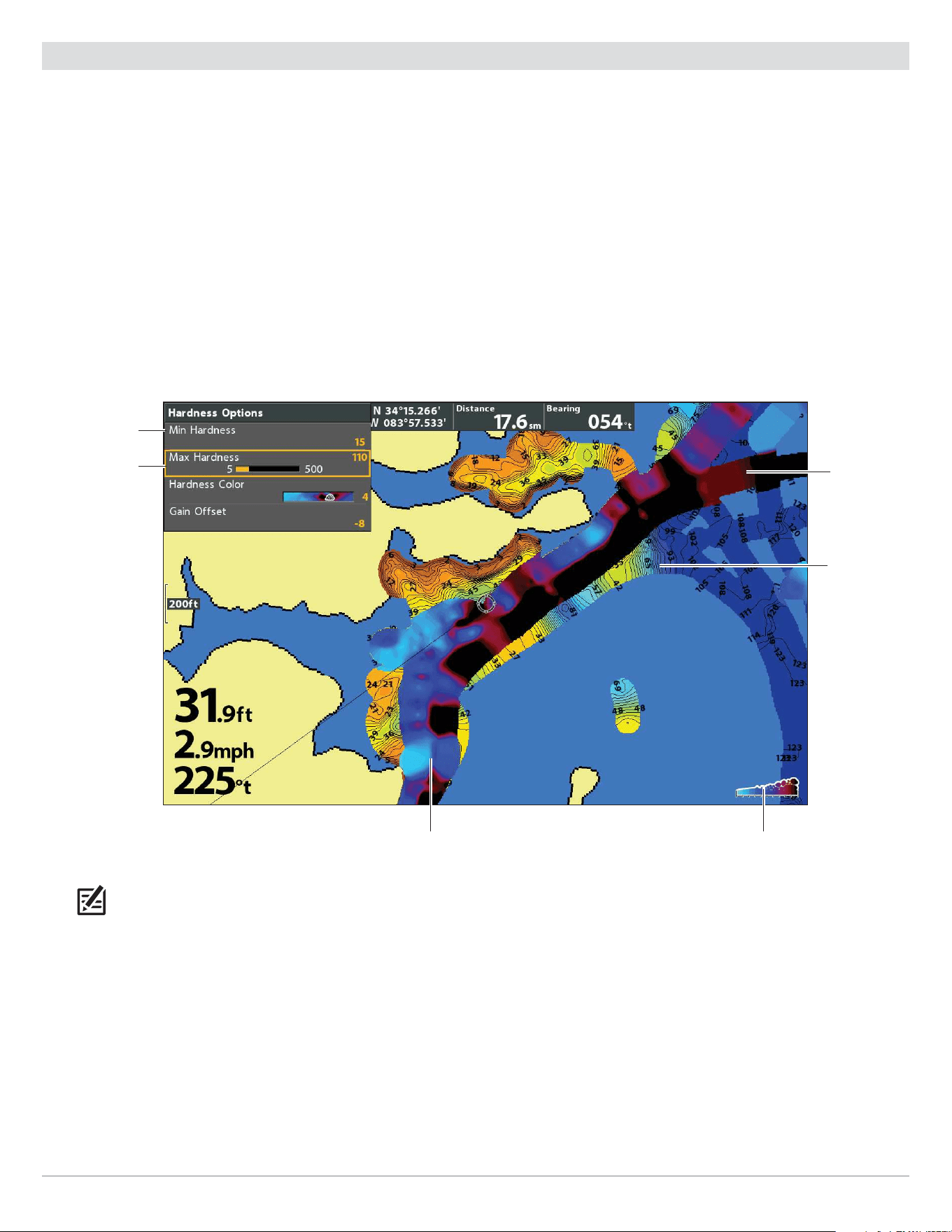
217
AutoChart Live
Adjust the Hardness Range
You can adjust the range of bottom hardness shown on the chart by changing the minimum range and maximum range on the
display. The range you select affects how the bottom hardness colors are displayed. The range is displayed in the AutoChart Color
Bar with Bottom Hardness selected.
1. From the AutoChart menu, select Hardness Options.
Press the RIGHT Cursor key.
2. Select Min Hardness.
3. Press the RIGHT or LEFT Cursor keys to adjust the setting.
4. Select Max Hardness.
5. Press the RIGHT or LEFT Cursor keys to adjust the setting.
AutoChart
Live Map
layer
hardness scale
(AutoChart Color Bar)
high range
Adjusting the Bottom Hardness Range (Map Source: Humminbird LakeMaster)
bottom
hardness
layer
bottom
hardness layer
low range
NOTE: Use the AutoChart Color Bar icon see the selected palette and, from left to right, the AutoChart Live depth range (low to
high), Bottom Hardness range (soft to hard), or Vegetation range (soft to hard).
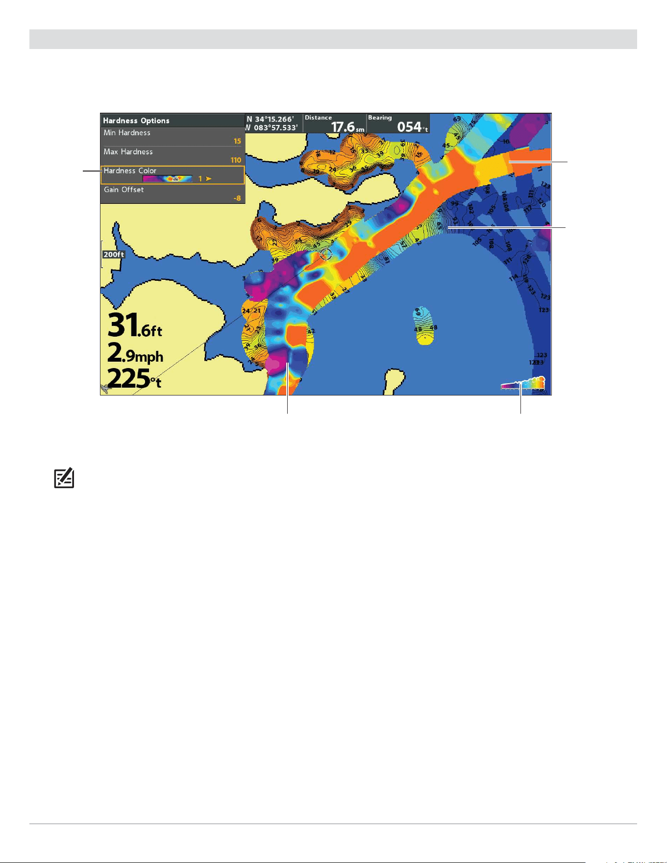
218
AutoChart Live
Change the Bottom Hardness Colors
Use the following instructions to change the color palette used to display Bottom Hardness.
AutoChart
Live Map
layer
hardness scale
(AutoChart Color Bar)
hardness
color
Changing the Bottom Hardness Colors (Map Source: Humminbird LakeMaster)
bottom
hardness
layer
bottom
hardness layer
NOTE: Use the AutoChart Color Bar icon see the selected palette and, from left to right, the AutoChart Live depth range (low to
high), Bottom Hardness range (soft to hard), or Vegetation range (soft to hard).
Change the Hardness Colors
The Hardness Color menu changes the colors used to display bottom hardness on the view. The color range is shown in the
AutoChart Color bar and is affected by the Min Hardness and Max Hardness settings. See Adjust the Hardness Range for more
information.
1. From the AutoChart menu, select Hardness Options.
Press the RIGHT Cursor key.
2. Select Hardness Color.
3. Select a palette.
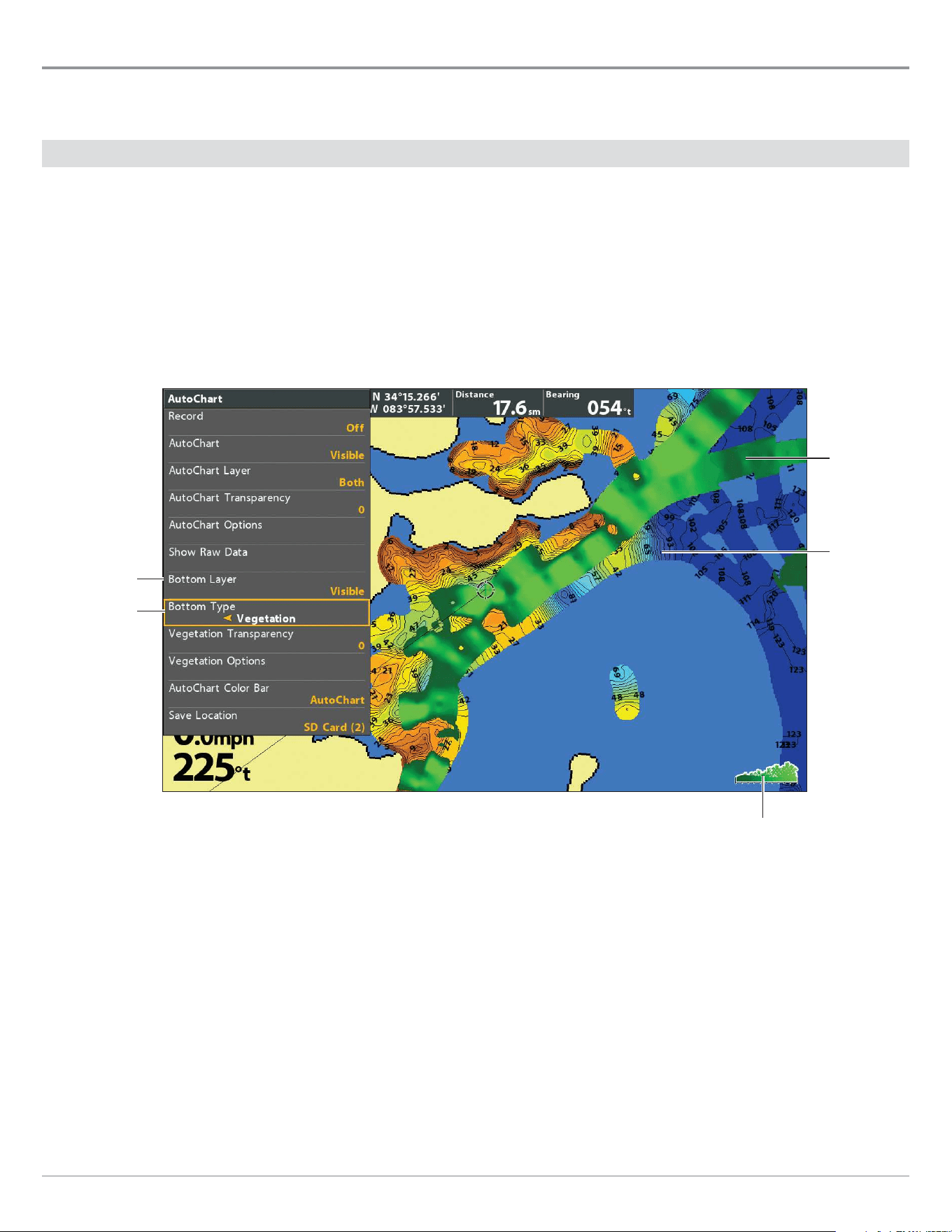
219
AutoChart Live
Customize the Vegetation Display Settings
The Bottom Layer is displayed on top of the AutoChart Live map and can be displayed as bottom hardness or vegetation. Vegetation
shows the sonar returns interpreted as vegetation on the Chart View.
Show/Hide Vegetation
Show Vegetation
1. From the AutoChart menu, select Bottom Layer.
2.
Select
Visible
(LakeMaster) or press the CHECK/INFO key or the RIGHT Cursor key to add a check mark (CoastMaster)
.
3. Select Bottom Type.
4. Select Vegetation.
AutoChart
Live Map
layer
vegetation scale
(AutoChart Color Bar)
bottom
layer set
to Visible
bottom type
Displaying the Vegetation Layer (Map Source: Humminbird LakeMaster)
vegetation
layer
Hide Vegetation
1. From the AutoChart Live menu, select Bottom Layer.
2. Select Hidden
(LakeMaster) or press the CHECK/INFO key or the RIGHT Cursor key to remove the check mark (CoastMaster)
.

220
AutoChart Live
Adjust the Gain Oset
Use Gain Offset to tune the vegetation display. Vegetation will vary with the lake, season, or environment you are fishing, and you
should adjust the Gain Offset as needed.
1. From the AutoChart menu, select Vegetation Options.
Press the RIGHT Cursor key.
2. Select Gain Offset.
3. Press the RIGHT or LEFT Cursor keys to adjust the setting.
Adjust the Vegetation Transparency
The bottom layer is displayed on top of the AutoChart Live map, and you can adjust the transparency to see different layers on the
view.
1. From the AutoChart menu, select Vegetation Transparency.
2. Press the RIGHT or LEFT Cursor keys to adjust the setting.
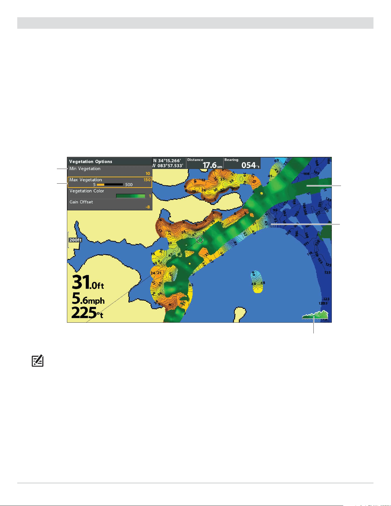
221
AutoChart Live
Adjust the Vegetation Range
You can adjust the range of vegetation shown on the chart by changing the minimum range and maximum range on the display.
The range you select affects how the vegetation colors are displayed.
1. From the AutoChart menu, select Vegetation Options.
Press the RIGHT Cursor key.
2. Select Min Vegetation.
3. Press the RIGHT or LEFT Cursor keys to adjust the setting.
4. Select Max Vegetation.
5. Press the RIGHT or LEFT Cursor keys to adjust the setting.
AutoChart
Live Map
layer
vegetation scale
(AutoChart Color Bar)
high range
Adjusting the Vegetation Range (Map Source: Humminbird LakeMaster)
vegetation
layer
low range
NOTE: Use the AutoChart Color Bar icon see the selected palette and, from left to right, the AutoChart Live depth range (low to
high), Bottom Hardness range (soft to hard), or Vegetation range (soft to hard).
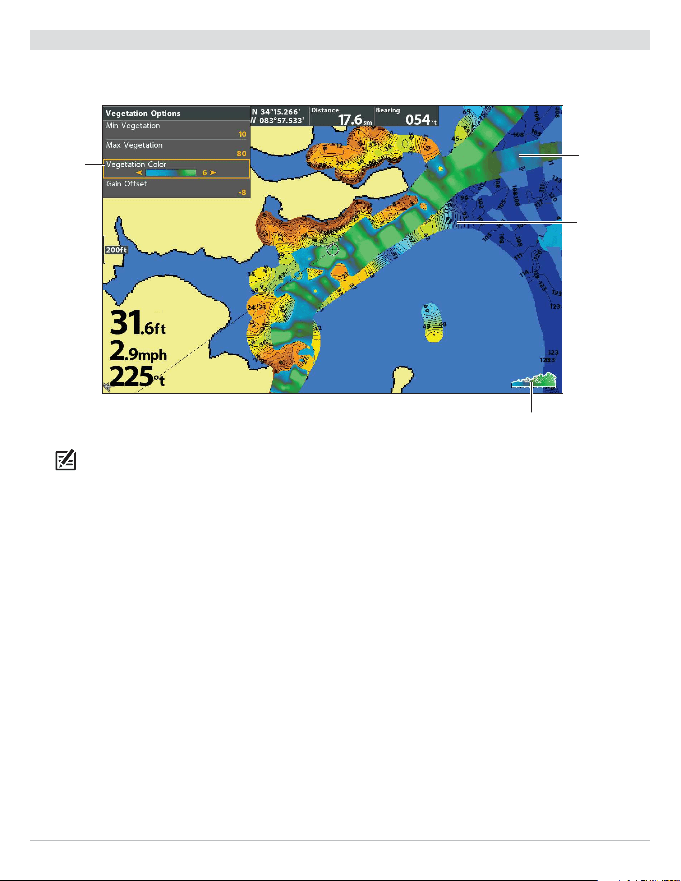
222
AutoChart Live
Change the Vegetation Colors
Use the following instructions to change the color palette used to display vegetation.
AutoChart
Live Map
layer
vegetation scale
(AutoChart Color Bar)
vegetation
color
Changing the Vegetation Colors (Map Source: Humminbird LakeMaster)
vegetation
layer
NOTE: Use the AutoChart Color Bar icon see the selected palette and, from left to right, the AutoChart Live depth range (low to
high), Bottom Hardness range (soft to hard), or Vegetation range (soft to hard).
Change the Vegetation Colors
The Vegetation Color menu changes the colors used to display vegetation on the view. The color range is shown in the AutoChart
Color bar and is affected by the Min Vegetation and Max Vegetation settings. See Adjust the Vegetation Range for more information.
1. From the AutoChart menu, select Vegetation Options.
Press the RIGHT Cursor key.
2. Select Vegetation Color.
3. Select a palette.

223
NMEA 2000 Setup
Set Up a NMEA 2000 Network
(G4N models only)
Use the instructions in this section if a NMEA 2000 network is connected to the control head.
When equipment is connected to the control head, the equipment and its data will be detected automatically. You can also manually
select equipment and set the data offset. The available menus are determined by the attached equipment.
NOTE: Humminbird recommends that the NMEA 2000 network be installed by a certified NMEA 2000 technician. See NMEA.org for
details.
Preparation
The NMEA 2000 network connects to the NMEA 2000 port on one control head. If you have a multi-control head network (separate
purchase required), select the control head that is connected to the NMEA 2000 network backbone to proceed with the following
instructions.
Turn On the NMEA 2000 Network
1. Main Menu (Custom User Mode): Press the MENU key twice. Select the Data Sources tab.
2. Select NMEA 2000 Network.
3. Press the RIGHT or LEFT Cursor keys to turn the NMEA 2000 Network on or off.
Select NMEA 2000 Data Sources
When equipment is connected to the control head, the equipment and its data will be detected automatically. Use the instructions
in this section to manually select devices to use on the NMEA 2000 network.
1. Main Menu: Press the MENU key twice. Select the Data Sources tab.
2. Select the Data Sources menu option. Press the RIGHT Cursor key to open the NMEA2K Sources menu.
3. Press the DOWN or UP Cursor key to select a source group.
4. Press the RIGHT Cursor key to open the submenu for that source.
5. Press the DOWN or UP Cursor key to select a data source. Press the RIGHT Cursor key or CHECK/INFO key to select the data
source.
6. Press the EXIT key to return to the NMEA2K Sources menu.
7. Repeat steps 3 – 6 to select another data source.
Set Data Offsets
Use the Data Offsets menu to adjust digital readouts by the amount you set.
1. Main Menu: Press the MENU key twice. Select the Data Sources tab.
2. Select Data Offsets. Press the RIGHT Cursor key to open the Data Offsets menu.
3. Select a data option. (Depth Adjustment, Heading Adjustment, NMEA 2K Heading Adjustment, Temp(Water) Adjustment, STW
Adjustment)
4. Press the RIGHT or LEFT Cursor keys to adjust the setting.

224
NMEA 2000 Setup
NMEA 2000 Messages (PGN)
The following NMEA 2000 input/output messages are available when NMEA 2000 is turned on and the related NMEA 2000 equipment
is detected and selected as a source.
Messages (PGN) Description Input Output
059392 ISO Acknowledgement
• •
059904 ISO Request
• •
060928 ISO Address Claim
• •
126208 NMEA - Command/Request/Acknowledge Function
• •
126464 Receive/Transmit PGN List Group Function
• •
126992 System Time
•
126996 Product Information
• •
127245 Rudder
•
127250 Vessel Heading
•
127251 Rate of Turn
•
127488 Engine Parameters, Rapid Update
•
127489 Engine Parameters - Dynamic
•
127497 Trip Parameters, Engine
•
127505 Fluid Level
•
128267 Water Depth
•
129026 COG & SOG, Rapid Update
•
129029 GNSS Position Data
•
129033 Time & Date
•
129283 Cross Track Error
•
129284 Navigation Data
•
129285 Navigation - Route/WP Information
•
129539 GNSS DOPs
•
129540 GNSS Sats in View
•
130052 Loran C TD Data
•
130306 Wind Data
•
130310 Environmental Parameters
•
130311 Environmental Parameters
•
130312 Temperature
•
130313 Humidity
•
130314 Actual Pressure
•
130576 Small Craft Status
•

225
ManageNMEA 2000 Setup
Change the Engine Source Assignments
The instructions in this section are optional and allow you to change which engine is assigned as the Engine 1 or Engine 2 source
in the control head.
1. Main Menu: Press the MENU key twice. Select the Data Sources tab.
2. Select the Data Sources menu option. Press the RIGHT Cursor key to open the NMEA2K Sources menu.
3. Select Engine 1 or Engine 2.
4. Press the Right Cursor key.
5. Select an Engine from the list and press the CHECK/INFO key or the RIGHT Cursor key.
Set the Fuel Tank Capacity
If there is a fuel flow rate sensor installed, but not a NMEA 2000 fuel tank sensor, use the instructions in this section to set up fuel
tank data manually.
1. Main Menu (Custom User Mode): Press the MENU key twice. Select the Data Sources tab.
2. Select Fuel Tank Override.
3. Use the RIGHT or LEFT Cursor keys to adjust the fuel tank capacity.
Refill the Fuel Tank
1. Main Menu (Custom User Mode): Press the MENU key twice. Select the Data Sources tab.
2. To fill the tank to the top, select Reset Total Fuel and press the RIGHT Cursor key.
Change Device or System Instance
The settings in this section are optional. You can use the default settings for Device Instance and System Instance or you can
customize them with your preferences. Use the Device Instance and System Instance settings to identify devices or groups of
devices outputting NMEA 2000 data on a network. Each device or group of devices outputting data on a single network must be
identified by a unique instance number.
For example, if your NMEA 2000 network includes two control heads outputting GPS data, set one control head to instance 1 and
the other to instance 2. The receiving device on the network can be set to receive GPS data from instance 1 or instance 2.
1. Main Menu (Custom User Mode): Press the MENU key twice. Select the Data Sources tab.
2. To identify a single device, select Device Instance.
To identify a group of devices, select System Instance.
3. Use the RIGHT or LEFT Cursor keys to select a unique number.
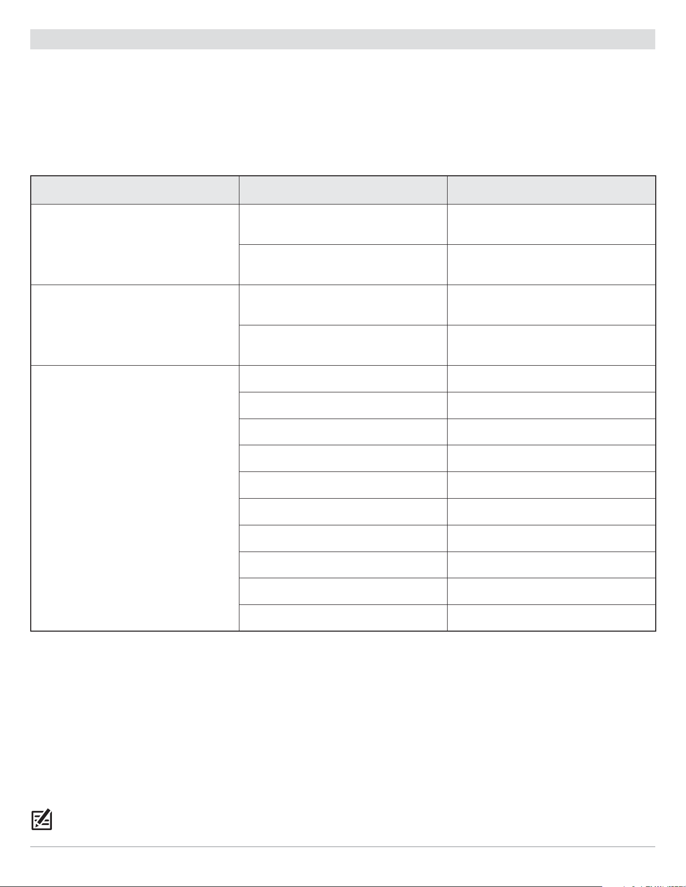
226
NMEA 2000 Setup
Set Alarms
Alarms are based on the limits you set for a device such as battery voltage, depth, water temperature, and more. Connecting to a
NMEA 2000 network adds the following NMEA 2000 Alarms to the Alarms tab:
• NMEA2K Depth
• NMEA2K Environment
• NMEA2K Engine
Each group expands into a submenu, which lists the alarms that fall under that group.
Menu Alarm Name Range
NMEA2K Depth
NMEA2K Shallow Water
Off, 1 – 100 feet, 0.5 – 30.0 meters* or
0.1 – 50 fathoms; Default = Off
NMEA2K Deep Water
Off, 1 – 100 feet, 0.5 – 30.0 meters* or
0.1 – 50 fathoms; Default = Off
NMEA2K Environment
NMEA2K Temperature (Air)
Off, - 40°F – +140° F or
- 40°C – + 60° C*; Default = Off
NMEA2K Temperature (Water)
Off, 33°F – 120°F or 1°C – 50°C*;
Default = Off
Total Fuel Off, 1% – 100%; Default = Off
Check Engine Off, On; Default = Off
Engine Over Temperature Off, On; Default = Off
Engine Low Oil Pressure Off, On; Default = Off
NMEA2K Engine
Engine Low Oil Level Off, On; Default = Off
Engine Low Fuel Pressure Off, On; Default = Off
Engine Low System Voltage Off, On; Default = Off
Engine Low Coolant Level Off, On; Default = Off
Engine Water Flow Off, On; Default = Off
Engine Charge Indicator Off, On; Default = Off
*International models only.
Set NMEA2K Alarms
1. Main Menu (Custom User Mode): Press the MENU key twice. Select the Alarms tab.
2. Select a NMEA2K alarm group. (NMEA2K Depth, NMEA2k Environment, NMEA2K Engine)
3. Press the RIGHT Cursor key to open the submenu.
4. Press the DOWN or UP Cursor key to select an alarm.
5. Press the RIGHT or LEFT Cursor key to adjust the setting.
6. Close: Press the EXIT key to return to the Alarms menu.
NOTE: When an alarm is triggered, you can silence it by pressing any key. The alarm will be silenced and will not be triggered again until
a new instance of the alarm condition is triggered.
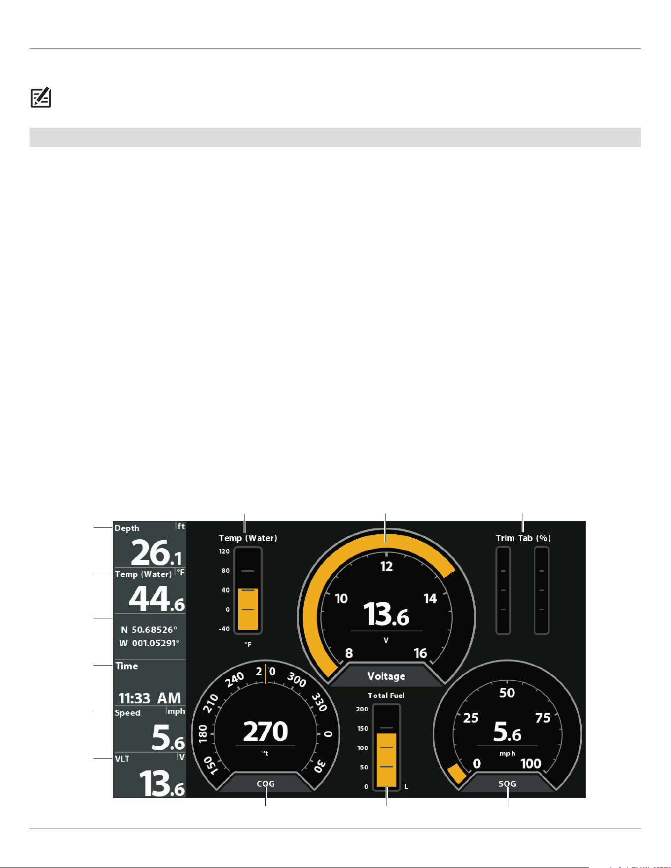
227
NMEA 2000 Setup
Understand the NMEA 2000 Instrument View
The NMEA 2000 Instrument View presents a full screen view of gauges and data boxes. It automatically displays a default data set,
or you can select the data readouts for the gauges and data boxes. You can also choose to hide the data boxes.
NOTE: The view must be displayed on the screen in order to change the digital readouts.
Select Readouts for the NMEA 2000 Instrument View
To customize data items displayed within the NMEA 2000 Instrument View, see the instructions below.
Customize Data Box Readouts
You can select the data that will be displayed in each box. Use the Edit Data Boxes menu to set your standard digital readouts. Use
the Edit Navigation Data Boxes menu to set the digital readouts that will be displayed during navigation.
1. NMEA 2000 X-Press Menu: With the NMEA 2000 Instrument View displayed on screen, press the MENU key once.
2. Select Edit Data Boxes or Edit Navigation Data boxes. Press the RIGHT Cursor key.
3. Select a Data Box (Data Box 1, 2, 3, etc.).
4. Select a digital readout.
Hide: To hide the data boxes, select Data Box. Use the LEFT Cursor key to select Off.
Customize Gauge Readouts
You can select the data that will be displayed by each gauge.
1. NMEA 2000 X-Press Menu: With the NMEA 2000 Instrument View displayed on screen, press the MENU key once.
2. Select Edit Gauges. Press the RIGHT Cursor key.
3. Select a Gauge (Gauge 1, 2, 3, etc.).
4. Select a digital readout.
data box 2
data box 1
data box 5
data box 4
data box 3
data box 6
NMEA 2000 View (HELIX 10)
gauge 1 gauge 2 gauge 3
gauge 4 gauge 5 gauge 6
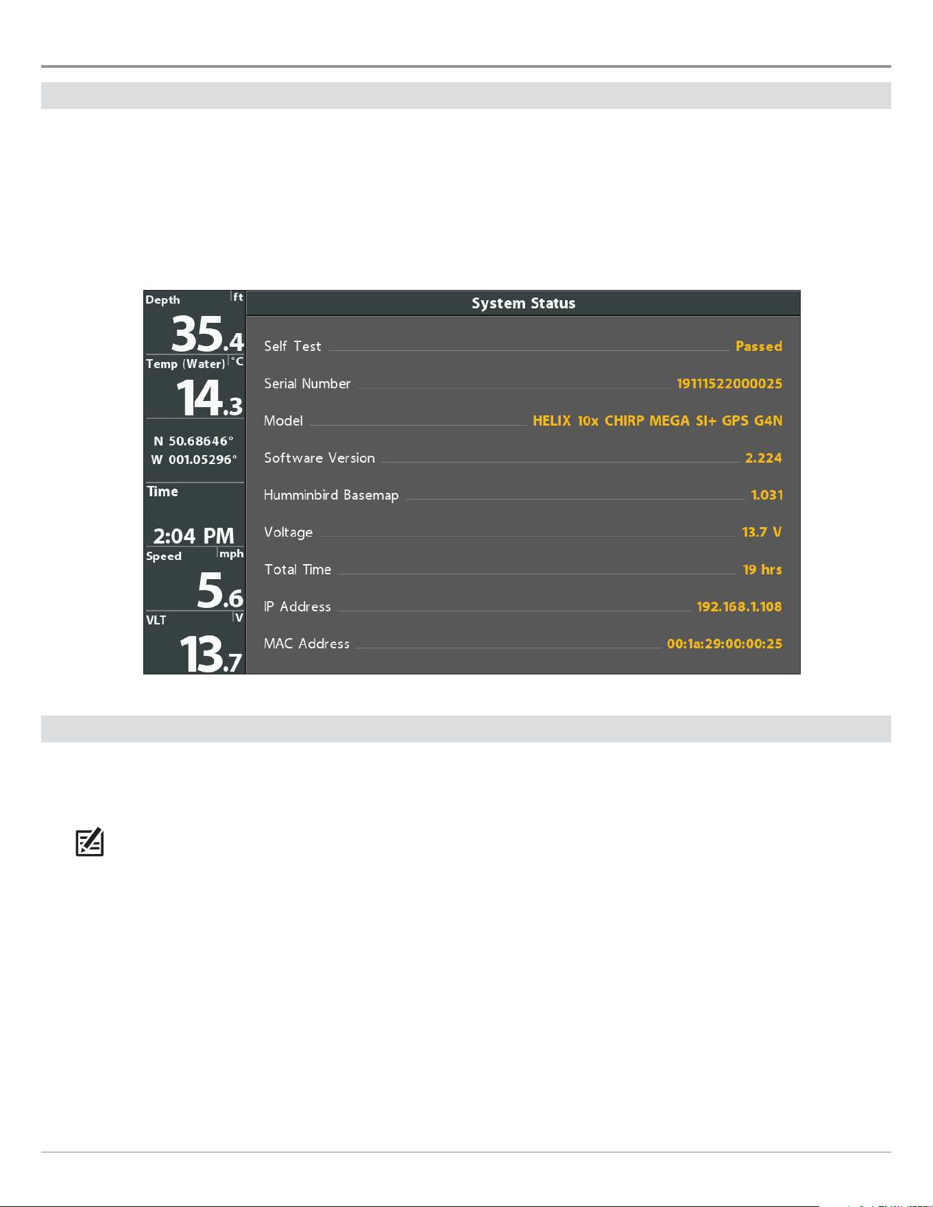
228
Manage your Control Head
Manage your Control Head
Check System Status
Use the System Status View to review control head information such as the software version and serial number.
1. Press and hold the VIEW key.
2. Select System. Press the RIGHT Cursor key.
3. Select System Status. Press the RIGHT Cursor key.
System Status View (HELIX 10 CHIRP MEGA SI+ GPS G4N)
Select an Installed GPS Receiver
The GPS Receiver Override menu is available when more than one GPS receiver is installed and detected by the control head. If GPS
Receiver Override is set to Auto, the control head will select a GPS receiver automatically. To manually select a GPS receiver, follow
the instructions in this section.
NOTE: If the control head is connected to an Ethernet network, this menu is not available. In this situation, use the Network
Source Setup dialog box to select a GPS source. For more information, download the Ethernet manual from our Web site at
humminbird.com.
1. Main Menu (Custom User Mode): Press the MENU key twice. Select the Nav tab.
2. Select GPS Receiver Override.
3. Select a GPS installation location.

229
Manage your Control Head
Set the GPS Output Frequency
GPS Output controls the frequency at which data from the GPS Receiver is sent to the control head. Select 10 Hz to receive the
most GPS updates on the display.
HELIX G3/G3N and older HELIX G4N
1. Main Menu (Custom User Mode): Press the MENU key
twice. Select the Setup tab.
2. Select GPS Output.
3. Press the RIGHT or LEFT Cursor keys to select a setting.
1. Main Menu (Custom User Mode): Press the MENU key
twice. Select the Data Sources tab.
2. Select GPS Settings and press the RIGHT Cursor key to
open the GPS Settings menu.
3. Select GPS Output.
4. Press the RIGHT or LEFT Cursor keys to select a setting.
Turn on/o GPS GLONASS
Use the following instructions to use GLONASS.
HELIX G3/G3N and older HELIX G4N
1. Main Menu (Custom User Mode): Press the MENU key
twice. Select the Setup tab.
2. Select GPS GLONASS.
3. Select On or Off.
1. Main Menu (Custom User Mode): Press the MENU key
twice. Select the Data Sources tab.
2. Select GPS Settings and press the RIGHT Cursor key to
open the GPS Settings menu.
3. Select GPS GLONASS.
4. Select On or Off.
Turn on/o NMEA 0183 Output
NMEA Output should be turned on if you connect the NMEA Output wires of an accessory GPS receiver (external) or heading sensor
cable to another NMEA-compatible device, such as an autopilot. See the accessory guide for details. Accessory guides can be
downloaded from our Web site at humminbird.com.
HELIX G3/G3N and older HELIX G4N
1. Main Menu (Custom User Mode): Press the MENU key
twice. Select the Setup tab.
2. Select NMEA 0183 Output.
3. Select On or Off.
1. Main Menu (Custom User Mode): Press the MENU key
twice. Select the Data Sources tab.
2. Select NMEA 0183 Output.
3. Select On or Off.

230
Manage your Control Head
If NMEA 0183 Output is turned on, the following sentences are output:
Message Description
APB Heading/Track Controller (Autopilot) Sentence “B” (navigation only)
BWR Bearing & Distance to Waypoint - Rhumb Line (navigation only)
DPT Depth
GGA Global Positioning System Fix Data
GLL Geographical Position - Latitude/Longitude
MTW Water Temperature
RMB Recommended Minimum Navigation Info (navigation only)
RMC Recommended Minimum Specification GNSS Data
VTG Track Made Good & Ground Speed
ZDA Time & Date
Configure the NMEA Talker ID
Use the following instructions to change the NMEA 0183 Talker ID to match the NMEA 0183 installed accessory.
HELIX G3/G3N and older HELIX G4N
1. Main Menu (Custom User Mode): Press the MENU key
twice. Select the Setup tab.
2. Select Configure NMEA Talker ID.
3. Select IN-Integrated Navigation (Default) or GP-Global
Positioning System.
1. Main Menu (Custom User Mode): Press the MENU key
twice. Select the Data Sources tab.
2. Select Configure NMEA Talker ID.
3. Select IN-Integrated Navigation (Default) or GP-Global
Positioning System.
Start the Timer
1. Main Menu: Press the MENU key twice. Select the Alarms tab.
2. Select Timer Setup. Press the RIGHT Cursor key.
3. Use the Cursor Control key to set the hours, minutes, and seconds.
4. To start the Timer immediately, select Start. Press the RIGHT Cursor key.
To save your settings and start the Timer at a later time, select Save. Press the RIGHT Cursor key.
NOTE: The Timer can be displayed as a digital readout. See Views: Display Digital Readouts.

231
Manage your Control Head
Change the Display Language
The available languages are determined by your Humminbird model.
WARNING! Do NOT enable Asian Mode if you do not require Asian languages. Before you select Asian Mode, contact Technical
Support for important information.
1. Main Menu: Press the MENU key twice. Select the Setup tab.
2. Select Language.
3. Press the RIGHT or LEFT Cursor keys to select a language.
Change Digital Readout Formats
Use the following instructions to customize the format for the digital readouts displayed on the control head. See Views: Display
Digital Readouts for more information.
Change the Digits Format
If you have Digital Readouts set to Boxes, you can change how the numbers are displayed.
HELIX G3/G3N and older HELIX G4N
1. Main Menu (Custom User Mode): Press the MENU key
twice. Select the Setup tab.
2. Select Digits Format.
3. Press the RIGHT or LEFT Cursor keys to select a format.
1. Main Menu (Custom User Mode): Press the MENU key
twice. Select the Data Sources tab.
2. Select Digits Format.
3. Press the RIGHT or LEFT Cursor keys to select a format.
Change Units of Measurement
HELIX G3/G3N and older HELIX G4N
1. Main Menu: Press the MENU key twice. Select the Setup
tab.
2. Select Units - Depth, Units - Distance, etc., and adjust
each
unit
setting
as needed.
3. Close: Press the EXIT key.
NOTE: The Units - Temp menu is only available in an
international model.
1. Main Menu: Press the MENU key twice. Select the Data
Sources tab.
2. Select Units and press the RIGHT Cursor key to open the
Units menu.
3. Select each
unit
as needed and use the RIGHT or LEFT Cursor
keys to adjust the setting.
4. Close: Press the EXIT key.
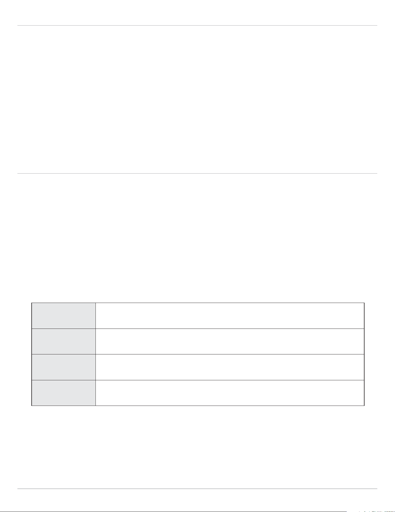
232
Manage your Control Head
Apply an Offset to a Digital Readout
Use the following instructions to adjust the digital readout by the offset amount entered. Depending on the attached sensors, you
can adjust the Depth Adjustment, Temp(Water) Adjustment, Heading Adjustment, NMEA 2k Heading Adjustment, and STW (Speed
Through Water) Adjustment from this menu.
For example, select Depth Offset to adjust the digital depth readout by the amount entered. To read the depth from the waterline,
enter a positive vertical measurement. To read the depth from the keel, enter a negative amount.
HELIX G3/G3N and older HELIX G4N
1. Main Menu (Custom User Mode): Press the MENU key
twice. Select the Setup tab.
2. Select each offset menu option as needed. Use the RIGHT
or LEFT Cursor keys to adjust the setting.
1. Main Menu (Custom User Mode): Press the MENU key
twice. Select the Data Sources tab.
2. Select Data Offsets and press the RIGHT Cursor key to open
the Data Offsets menu.
3. Select each offset as needed and use the RIGHT or LEFT
Cursor keys to adjust the setting.
Change the Latitude/Longitude Format
HELIX G3/G3N and older HELIX G4N
1. Main Menu (Custom User Mode): Press the MENU key
twice. Select the Setup tab.
2. Select Position Format.
3. Press the RIGHT or LEFT Cursor keys to select a format.
1. Main Menu (Custom User Mode): Press the MENU key
twice. Select the Data Sources tab.
2. Select GPS Settings and press the RIGHT Cursor key to
open the GPS Settings Menu.
3. Select Position Format.
4. Press the RIGHT or LEFT Cursor keys to select a format.
Change the Time and Date Format
1. Main Menu (Custom User Mode): Press the MENU key twice. Select the Setup tab.
2. Select one of the following menus. Press the RIGHT or LEFT Cursor keys to select a format.
Local Time Zone Select your time zone.
Daylight Saving
Time
To add one hour to the time displayed in the local time zone, select On.
Time Format Select a time format. International models only.
Date Format Select a date format. International models only.

233
Manage your Control Head
Turn o Demonstration Mode
The control head will start demonstration mode if a start up mode is not selected when the unit is first turned on (see Getting
Started). If the screen is displaying tips, menus, and views automatically, it is in Demonstration mode. Use the following instructions
to turn off Demonstration mode.
NOTE: Menu settings cannot be saved in Demonstration mode.
1. Main Menu: Press the MENU key twice. Select the Setup tab.
2. Select Demonstration.
3. Select Off.
Adjust the Backlight
1. Press the POWER key.
2. Select Light.
3. Adjust the Backlight setting from Dim to 10 (brightest).
Start Standby Mode
To conserve power while the control head is not in-use, start Standby mode.
1. Press the POWER key.
2. Select Standby.
3. Press the RIGHT Cursor key.
4. Turn off: Press the POWER key.
Restore System Defaults
Use the following instructions to reset ALL menu settings to the factory defaults.
CAUTION! Use this menu with caution!
1. Main Menu: Press the MENU key twice. Select the Setup tab.
2. Select Restore Defaults.
3. Press the RIGHT Cursor key.
4. Follow the on-screen prompts to confirm the reset.

234
Maintenance
Maintenance
Your control head is designed to provide years of trouble-free use with very little maintenance. Use the following procedures to
ensure your Humminbird continues to deliver top performance.
Control Head Maintenance
It is important to consider the following precautions when using your Humminbird control head:
• Chemicals, such as those found in bug spray and sunscreen, may cause permanent damage to the control head screen. Such
damage is not covered by the warranty.
• NEVER leave the control head in a closed car or trunk. The high temperatures generated in hot weather can damage the
electronics.
• When the control head is not in use, cover the unit with the control head cover.
• Repairs should be performed only by an authorized technician.
Use the following information to keep the control head and screen clean.
• Screen: To clean the control head screen, use a mild soap (such as a non-abrasive liquid hand soap) and warm water. Wipe
the screen dry with a soft cloth. Be careful to avoid scratching the screen. If water spots remain, use a solution of water and
vinegar.
WARNING! Do not use a chemical glass cleaner on the screen. Chemicals in the solution may cause cracking in the lens of the unit.
NOTE: Do not wipe the screen while dirt or grease is on the screen.
• Control Head: If the control head comes into contact with salt spray, wipe the affected surfaces with a cloth dampened with
fresh water.
Transducer Maintenance
Use the following information to maintain the transducer operation.
• If your boat remains in the water for long periods of time, algae and other marine growth can reduce the effectiveness of the
transducer. Periodically clean the face of the transducer with a mild, marine-safe and plastic-safe soap or solution.
NOTE: To clean the transducer, you may need to pivot the transducer up in the bracket.
• If your boat remains out of the water for a long period of time, it may take some time to wet the transducer when it is returned
to the water. Small air bubbles can climb to the surface of the transducer and interfere with proper operation. These bubbles
dissipate with time, or you can wipe the face of the transducer with your fingers after the transducer is in the water.

235
Troubleshooting
Troubleshooting
Before contacting Humminbird Technical Support, please read the following section. Taking the time to review these troubleshooting
guidelines may allow you to solve a performance problem yourself, and therefore avoid sending your unit back for repair.
Control Head Doesn’t Power Up
If your control head doesn’t power up, use the installation guide to confirm the following:
• the power cable is properly connected to the control head
• the power cable is wired correctly, with red to positive battery terminal and black to negative terminal or ground
• the fuse is operational
• the battery voltage of the power connector is at least 12.2 Volts
Correct any known problems, including removing corrosion from the battery terminals or wiring, or replacing the battery if necessary.
Also, visit humminbird.com to download our Power Troubleshooting Guide.
Control Head Doesn’t Detect the Connected Transducer
A connected and functioning transducer will automatically be detected by the control head. The control head will default to the
transducer that was included with your unit and automatically select sonar settings based on the transducer’s capabilities. If, when
you power up the control head, it does not automatically select sonar settings or display sonar data, even though a transducer is
already connected, this means that the control head is not detecting the transducer. Perform the following troubleshooting tasks:
• Using the transducer installation guide, check to make sure that the transducer cable is securely connected to the control
head. Reconnect if necessary, and power up the unit again to see if this fixes the problem.
• Replace the non-functioning transducer with a known good transducer if available and power up the control head again.
• Check the transducer cable. Replace the transducer if the cable is damaged or corroded.
Control Head Doesn’t Detect a Connected Accessory
A connected and functioning accessory will automatically be detected by the control head. If you connected an accessory to the
control head and the accessory is not detected by the control head, try the following:
• Check to make sure that the accessory cable is securely connected to the control head. Reconnect the cable, if necessary.
• Confirm the accessory is connected to a stable and reliable power source.
• Entire System Restart: Power off all control heads and connected equipment. Wait 10 seconds, and then power on all equipment.

236
Troubleshooting
Display Problems
There are several main conditions or sources of possible interference that may cause problems with the quality of the information
displayed on the control head. Look in the following table for some symptoms of display problems and possible solutions:
Display Problems Possible Solutions
The control head loses power at high
speeds.
If the power output of your boat’s engine is unregulated, the control head may be
protecting itself using its over-voltage protection feature. Make sure the input voltage
does not exceed 20 Volts.
When the boat moves at higher speeds,
the bottom disappears or suddenly
weakens, or the display contains gaps.
The transducer position may need to be adjusted. A mix of air and water flowing around
the transducer (cavitation) may be interfering with the interpretation of sonar data.
See the transducer installation guide for instructions to adjust the transducer position.
Electrical noise from the boat’s engine may be interfering with sonar reception. See
Finding the Cause of Noise for more information.
There are no fish detected, even when you
know they are in the water under the boat,
or sonar readings seem weak or faulty.
Sonar readings may be affected if the transducer is not positioned correctly (such
as mounted at an angle, not straight down), or there is some kind of mechanical
interference, either because it is mounted inside a hull that is too thick for proper sonar
transmission, the bond between the transducer and the hull is not airtight, or because
the transducer is dirty. See the transducer installation guide to adjust the transducer
position, and make sure the transducer is clean.
Low battery voltage may be affecting the power of signal transmission.
Electrical noise from the boat’s engine may be interfering with sonar reception. See
Finding the Cause of Noise for more information.
Finding the Cause of Noise
Electrical noise usually affects the display with many black dots at high speeds, and high sensitivity readings. See the table below
for possible sources that can cause noise or interference.
Possible Source of Noise Isolation
Other electronic devices
Turn off any nearby electronic devices to see if the problem goes away, then turn them
on one at a time to see if the noise re-appears.
The boat’s engine
To determine whether the boat’s engine is the source of the noise, increase the RPMs
while the boat is in neutral and stationary to see if the noise increases proportionately.
If the noise appears when you rev the engine, the problem could be the spark plugs,
alternator, or tachometer wiring. Replace the spark plugs with resistor plugs, install an
alternator filter, or route the control head power and transducer cables away from the
engine wiring.
Cavitation from the boat’s propeller
Turbulence created by the propeller can cause noise. Confirm the transducer has been
properly installed according to its specific mounting requirements (see the transducer
installation guide for details). Also, make sure that the water flows smoothly over the
face of the transducer at all times.

237
Specifications
Specifications
HELIX 5 SONAR G2
Control Head
Display Size (diagonal) ................................................................................... 5 inches (127 mm)
Pixel Matrix .............................................................................................. WVGA 480V x 800H
Display Type ...................................................................................................... TFT Color
Backlight .............................................................................................................. LED
Communication ................................................................................................. NMEA 0183
Power Input ................................................................................................... 10 to 20 VDC
Current Draw ....................................................................................................... 650 mA
IPX Rating ................................................................. IPX7 Waterproof/Submersible @ 1 m for 30 minutes
DualBeam PLUS Transducer
XNT 9 20 T (includes built-in temperature probe)
Operating Frequency ........................................................................................ 200 kHz, 83 kHz
Depth Capability ............................................................................................ 1500 ft (457 m)
Area of Coverage ............................................................... 60°@-10 dB in 83 kHz, 20°@-10 dB in 200 kHz
Power Output (MAX) .............................................................. 500 Watts (RMS), 4000 Watts (Peak to Peak)
NOTE: Humminbird verifies maximum stated depth in saltwater conditions, but actual depth performance may vary due to
transducer installation, water type, thermal layers, bottom composition, and slope.
NOTE: Product specifications and features are subject to change without notice.

238
Specifications
ICE HELIX 5 CHIRP G2
Control Head
Display Size (diagonal) ................................................................................... 5 inches (127 mm)
Pixel Matrix .............................................................................................. WVGA 480V x 800H
Display Type ...................................................................................................... TFT Color
Backlight .............................................................................................................. LED
Communication ................................................................................................. NMEA 0183
Power Input ................................................................................................... 10 to 20 VDC
Current Draw ....................................................................................................... 600 mA
IPX Rating ................................................................. IPX7 Waterproof/Submersible @ 1 m for 30 minutes
Dual Spectrum ICE Transducer
XI 9 1521
Default Operating Frequency ............................................................................... 150 kHz - 220 kHz
Depth Capability ............................................................................................. 400 ft (122 m)
Area of Coverage ............................................................................. 15°-21°@-3 dB in 130-250 kHz
Power Output (MAX) .............................................................. 500 Watts (RMS), 4000 Watts (Peak to Peak)
NOTE: Humminbird verifies maximum stated depth in saltwater conditions, but actual depth performance may vary due to
transducer installation, water type, thermal layers, bottom composition, and slope.
NOTE: Product specifications and features are subject to change without notice.

239
Specifications
HELIX 5 CHIRP GPS G2
Control Head
Display Size (diagonal) ................................................................................... 5 inches (127 mm)
Pixel Matrix .............................................................................................. WVGA 480V x 800H
Display Type ...................................................................................................... TFT Color
Backlight .............................................................................................................. LED
Communication ................................................................................................. NMEA 0183
Power Input ................................................................................................... 10 to 20 VDC
Current Draw ....................................................................................................... 600 mA
IPX Rating ................................................................. IPX7 Waterproof/Submersible @ 1 m for 30 minutes
CHIRP DualBeam PLUS Transducer
XNT 9 20 T (includes built-in temperature probe)
Operating Frequency ........................................................................................ 200 kHz, 83 kHz
Depth Capability ............................................................................................ 1500 ft (457 m)
Area of Coverage ............................................................... 60°@-10 dB in 83 kHz, 20°@-10 dB in 200 kHz
Power Output (MAX) .............................................................. 500 Watts (RMS), 4000 Watts (Peak to Peak)
NOTE: Humminbird verifies maximum stated depth in saltwater conditions, but actual depth performance may vary due to
transducer installation, water type, thermal layers, bottom composition, and slope.
NOTE: Product specifications and features are subject to change without notice.

240
Specifications
ICE HELIX 5 CHIRP GPS G2
Control Head
Display Size (diagonal) ................................................................................... 5 inches (127 mm)
Pixel Matrix .............................................................................................. WVGA 480V x 800H
Display Type ...................................................................................................... TFT Color
Backlight .............................................................................................................. LED
Communication ................................................................................................. NMEA 0183
Power Input ................................................................................................... 10 to 20 VDC
Current Draw ....................................................................................................... 600 mA
IPX Rating ................................................................. IPX7 Waterproof/Submersible @ 1 m for 30 minutes
Dual Spectrum ICE Transducer
XI 9 1521
Default Operating Frequency ............................................................................... 150 kHz - 220 kHz
Depth Capability ............................................................................................. 400 ft (122 m)
Area of Coverage ............................................................................. 15°-21°@-3 dB in 130-250 kHz
Power Output (MAX) .............................................................. 500 Watts (RMS), 4000 Watts (Peak to Peak)
CHIRP DualBeam PLUS Transducer
XNT 9 20 T (included with All-Season model only; includes built-in temperature probe)
Operating Frequency ........................................................................................ 200 kHz, 83 kHz
Depth Capability ............................................................................................ 1500 ft (457 m)
Area of Coverage ............................................................... 60°@-10 dB in 83 kHz, 20°@-10 dB in 200 kHz
Power Output (MAX) .............................................................. 500 Watts (RMS), 4000 Watts (Peak to Peak)
NOTE: Humminbird verifies maximum stated depth in saltwater conditions, but actual depth performance may vary due to
transducer installation, water type, thermal layers, bottom composition, and slope.
NOTE: Product specifications and features are subject to change without notice.

241
Specifications
HELIX 5 DI G2
Control Head
Display Size (diagonal) ................................................................................... 5 inches (127 mm)
Pixel Matrix .............................................................................................. WVGA 480V x 800H
Display Type ...................................................................................................... TFT Color
Backlight .............................................................................................................. LED
Communication ................................................................................................. NMEA 0183
Power Input ................................................................................................... 10 to 20 VDC
Current Draw ....................................................................................................... 650 mA
IPX Rating ................................................................. IPX7 Waterproof/Submersible @ 1 m for 30 minutes
Down Imaging Transducer
XNT 9 DI T (includes built-in temperature probe)
Down Imaging
Operating Frequency ....................................................................................... 455 kHz, 800 kHz
Depth Capability ............................................................................................. 350 ft (107 m)
Area of Coverage .............................................................75º @ -10 dB in 455 kHz, 45º @ -10 dB in 800 kHz
Power Output (MAX) .............................................................. 500 Watts (RMS), 4000 Watts (Peak to Peak)
DualBeam PLUS
Operating Frequency ....................................................................................... 200 kHz, 455 kHz
Depth Capability ............................................................................................. 600 ft (183 m)
Area of Coverage .............................................................28° @ -10 dB in 200 kHz, 16° @ -10 dB in 455 kHz
Power Output (MAX) .............................................................. 500 Watts (RMS), 4000 Watts (Peak to Peak)
NOTE: Humminbird verifies maximum stated depth in saltwater conditions, but actual depth performance may vary due to
transducer installation, water type, thermal layers, bottom composition, and slope.
NOTE: Product specifications and features are subject to change without notice.

242
Specifications
HELIX 5 CHIRP DI GPS G2
Control Head
Display Size (diagonal) ................................................................................... 5 inches (127 mm)
Pixel Matrix .............................................................................................. WVGA 480V x 800H
Display Type ...................................................................................................... TFT Color
Backlight .............................................................................................................. LED
Communication ................................................................................................. NMEA 0183
Power Input ................................................................................................... 10 to 20 VDC
Current Draw ....................................................................................................... 600 mA
IPX Rating ................................................................. IPX7 Waterproof/Submersible @ 1 m for 30 minutes
CHIRP Down Imaging Transducer
XNT 9 DI T (includes built-in temperature probe)
Down Imaging
Operating Frequency ....................................................................................... 455 kHz, 800 kHz
Depth Capability ............................................................................................. 350 ft (107 m)
Area of Coverage .............................................................75º @ -10 dB in 455 kHz, 45º @ -10 dB in 800 kHz
Power Output (MAX) .............................................................. 500 Watts (RMS), 4000 Watts (Peak to Peak)
DualBeam PLUS
Operating Frequency ....................................................................................... 200 kHz, 455 kHz
Depth Capability ............................................................................................. 600 ft (183 m)
Area of Coverage .............................................................28° @ -10 dB in 200 kHz, 16° @ -10 dB in 455 kHz
Power Output (MAX) .............................................................. 500 Watts (RMS), 4000 Watts (Peak to Peak)
NOTE: Humminbird verifies maximum stated depth in saltwater conditions, but actual depth performance may vary due to
transducer installation, water type, thermal layers, bottom composition, and slope.
NOTE: Product specifications and features are subject to change without notice.

243
Specifications
HELIX 5 CHIRP SI GPS G2
Control Head
Display Size (diagonal) ................................................................................... 5 inches (127 mm)
Pixel Matrix .............................................................................................. WVGA 480V x 800H
Display Type ...................................................................................................... TFT Color
Backlight .............................................................................................................. LED
Communication ................................................................................................. NMEA 0183
Power Input ................................................................................................... 10 to 20 VDC
Current Draw ....................................................................................................... 600 mA
IPX Rating ................................................................. IPX7 Waterproof/Submersible @ 1 m for 30 minutes
CHIRP Side Imaging Transducer
XNT 9 SI 180 T (includes built-in temperature probe)
Side Imaging
Operating Frequency ............................................................................................... 455 kHz
Side Imaging Range Capability ...................................................................... 200 ft (61 m) Side to Side
Area of Coverage ............................................................ (2) 86º @ -10 dB in 455 kHz (180º Total Coverage)
Power Output (MAX) .............................................................. 500 Watts (RMS), 4000 Watts (Peak to Peak)
DualBeam PLUS
Operating Frequency ........................................................................................ 200 kHz, 83 kHz
Depth Capability ............................................................................................ 1500 ft (457 m)
Area of Coverage ............................................................. 60° @ -10 dB in 83 kHz, 20° @ -10 dB in 200 kHz
Power Output (MAX) .............................................................. 500 Watts (RMS), 4000 Watts (Peak to Peak)
NOTE: Humminbird verifies maximum stated depth in saltwater conditions, but actual depth performance may vary due to
transducer installation, water type, thermal layers, bottom composition, and slope.
NOTE: Product specifications and features are subject to change without notice.

244
Specifications
HELIX 5 GPS G2
Control Head
Display Size (diagonal) ................................................................................... 5 inches (127 mm)
Pixel Matrix .............................................................................................. WVGA 480V x 800H
Display Type ...................................................................................................... TFT Color
Backlight .............................................................................................................. LED
Communication ................................................................................................. NMEA 0183
Power Input ................................................................................................... 10 to 20 VDC
Current Draw ....................................................................................................... 600 mA
IPX Rating ................................................................. IPX7 Waterproof/Submersible @ 1 m for 30 minutes
NOTE: Product specifications and features are subject to change without notice.

245
Specifications
ICE HELIX 5 CHIRP G3
Control Head
Display Size (diagonal) ................................................................................... 5 inches (127 mm)
Pixel Matrix .............................................................................................. WVGA 480V x 800H
Display Type ...................................................................................................... TFT Color
Backlight .............................................................................................................. LED
Communication ................................................................................................. NMEA 0183
Power Input ................................................................................................... 10 to 20 VDC
Current Draw ....................................................................................................... 600 mA
IPX Rating ................................................................. IPX7 Waterproof/Submersible @ 1 m for 30 minutes
Dual Spectrum ICE Transducer
XI 9 1521
Default Operating Frequency ............................................................................... 150 kHz - 220 kHz
Depth Capability ............................................................................................. 400 ft (122 m)
Area of Coverage ............................................................................. 15°-21°@-3 dB in 130-250 kHz
Power Output (MAX) .............................................................. 500 Watts (RMS), 4000 Watts (Peak to Peak)
NOTE: Humminbird verifies maximum stated depth in saltwater conditions, but actual depth performance may vary due to
transducer installation, water type, thermal layers, bottom composition, and slope.
NOTE: Product specifications and features are subject to change without notice.

246
Specifications
HELIX 5 CHIRP GPS G3
Control Head
Display Size (diagonal) ................................................................................... 5 inches (127 mm)
Pixel Matrix .............................................................................................. WVGA 480V x 800H
Display Type ...................................................................................................... TFT Color
Backlight .............................................................................................................. LED
Communication ................................................................................................. NMEA 0183
Power Input ................................................................................................... 10 to 20 VDC
Current Draw ....................................................................................................... 600 mA
IPX Rating ................................................................. IPX7 Waterproof/Submersible @ 1 m for 30 minutes
Dual Spectrum 2D CHIRP Transducer
XNT 9 HW T (includes built-in temperature probe)
Default Operating Frequency ............................................................................... 150 kHz - 220 kHz
Depth Capability ............................................................................................ 1000 ft (305 m)
Area of Coverage ............................................................................ Full: 42°@-10 dB in 150-220 kHz
Wide: 42°@-10 dB in 140-200 kHz
Narrow: 25°@-10 dB in 180-240 kHz
Power Output (MAX) .............................................................. 500 Watts (RMS), 4000 Watts (Peak to Peak)
NOTE: Humminbird verifies maximum stated depth in saltwater conditions, but actual depth performance may vary due to
transducer installation, water type, thermal layers, bottom composition, and slope.
NOTE: Product specifications and features are subject to change without notice.

247
Specifications
ICE HELIX 5 CHIRP GPS G3
Control Head
Display Size (diagonal) ................................................................................... 5 inches (127 mm)
Pixel Matrix .............................................................................................. WVGA 480V x 800H
Display Type ...................................................................................................... TFT Color
Backlight .............................................................................................................. LED
Communication ................................................................................................. NMEA 0183
Power Input ................................................................................................... 10 to 20 VDC
Current Draw ....................................................................................................... 600 mA
IPX Rating ................................................................. IPX7 Waterproof/Submersible @ 1 m for 30 minutes
Dual Spectrum ICE Transducer
XI 9 1521
Default Operating Frequency ............................................................................... 150 kHz - 220 kHz
Depth Capability ............................................................................................. 400 ft (122 m)
Area of Coverage ............................................................................. 15°-21°@-3 dB in 130-250 kHz
Power Output (MAX) .............................................................. 500 Watts (RMS), 4000 Watts (Peak to Peak)
Dual Spectrum 2D CHIRP Transducer
XNT 9 HW T (included with All-Season model only; includes built-in temperature probe)
Default Operating Frequency ............................................................................... 150 kHz - 220 kHz
Depth Capability ............................................................................................ 1000 ft (305 m)
Area of Coverage ............................................................................ Full: 42°@-10 dB in 150-220 kHz
Wide: 42°@-10 dB in 140-200 kHz
Narrow: 25°@-10 dB in 180-240 kHz
Power Output (MAX) .............................................................. 500 Watts (RMS), 4000 Watts (Peak to Peak)
NOTE: Humminbird verifies maximum stated depth in saltwater conditions, but actual depth performance may vary due to
transducer installation, water type, thermal layers, bottom composition, and slope.
NOTE: Product specifications and features are subject to change without notice.

248
Specifications
HELIX 5 CHIRP DI GPS G3
Control Head
Display Size (diagonal) ................................................................................... 5 inches (127 mm)
Pixel Matrix .............................................................................................. WVGA 480V x 800H
Display Type ...................................................................................................... TFT Color
Backlight .............................................................................................................. LED
Communication ................................................................................................. NMEA 0183
Power Input ................................................................................................... 10 to 20 VDC
Current Draw ....................................................................................................... 600 mA
IPX Rating ................................................................. IPX7 Waterproof/Submersible @ 1 m for 30 minutes
Dual Spectrum CHIRP Down Imaging Transducer
XNT 9 HW DI T (includes built-in temperature probe)
Down Imaging
Operating Frequency ............................................................................................... 455 kHz
Depth Capability ..................................................................................... 455 kHz: 400 ft (107 m)
Area of Coverage ............................................................................455 kHz: 75° @ -10 dB in 455 kHz
Power Output (MAX) .............................................................. 500 Watts (RMS), 4000 Watts (Peak to Peak)
Dual Spectrum
Default Operating Frequency ............................................................................... 150 kHz - 220 kHz
Depth Capability ............................................................................................ 1200 ft (366 m)
Area of Coverage ............................................................................ Full: 42°@-10 dB in 150-220 kHz
Wide: 42°@-10 dB in 140-200 kHz
Narrow: 25°@-10 dB in 180-240 kHz
Power Output (MAX) .............................................................. 500 Watts (RMS), 4000 Watts (Peak to Peak)
NOTE: Humminbird verifies maximum stated depth in saltwater conditions, but actual depth performance may vary due to
transducer installation, water type, thermal layers, bottom composition, and slope.
NOTE: Product specifications and features are subject to change without notice.
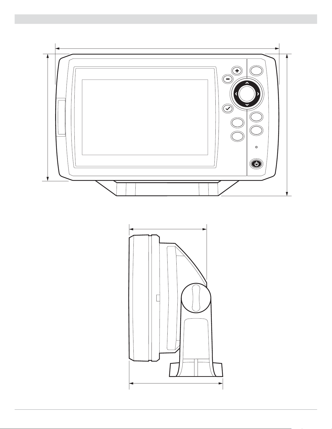
249
Specifications
HELIX 5 Control Head Measurements
HELIX 5 Gimbal Mount
VIEW
MENU
EXIT
MARK
GOTO
7.55 in (191.77 mm)
4.28 in
(108.71 mm)
4.64 in
(117.86 mm)
2.90 in (73.66 mm)
3.30 in (83.82 mm)
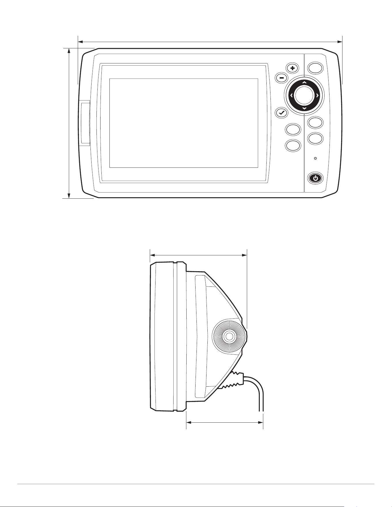
250
Specifications
HELIX 5 In-Dash Mount
VIEW
MENU
EXIT
MARK
GOTO
MOB
7.55 in (191.77 mm)
4.28 in
(108.71 mm)
2.90 in (73.66 mm)
2.17 in (55.12 mm)

251
Specifications
HELIX 7 SONAR G2
Control Head
Display Size (diagonal) ................................................................................... 7 inches (178 mm)
Pixel Matrix .............................................................................................. WVGA 480V x 800H
Display Type ...................................................................................................... TFT Color
Backlight .............................................................................................................. LED
Communication ................................................................................................. NMEA 0183
Power Input ................................................................................................... 10 to 20 VDC
Current Draw ....................................................................................................... 800 mA
IPX Rating ................................................................. IPX7 Waterproof/Submersible @ 1 m for 30 minutes
DualBeam PLUS Transducer
XNT 9 20 T (includes built-in temperature probe)
Operating Frequency ........................................................................................ 200 kHz, 83 kHz
Depth Capability ............................................................................................ 1500 ft (457 m)
Area of Coverage ............................................................... 60°@-10 dB in 83 kHz, 20°@-10 dB in 200 kHz
Power Output (MAX) .............................................................. 500 Watts (RMS), 4000 Watts (Peak to Peak)
NOTE: Humminbird verifies maximum stated depth in saltwater conditions, but actual depth performance may vary due to
transducer installation, water type, thermal layers, bottom composition, and slope.
NOTE: Product specifications and features are subject to change without notice.

252
Specifications
HELIX 7 CHIRP GPS G2
Control Head
Display Size (diagonal) ................................................................................... 7 inches (178 mm)
Pixel Matrix .............................................................................................. WVGA 480V x 800H
Display Type ...................................................................................................... TFT Color
Backlight .............................................................................................................. LED
Communication ................................................................................................. NMEA 0183
Power Input ................................................................................................... 10 to 20 VDC
Current Draw ....................................................................................................... 850 mA
IPX Rating ................................................................. IPX7 Waterproof/Submersible @ 1 m for 30 minutes
CHIRP DualBeam PLUS Transducer
XNT 9 20 T (includes built-in temperature probe)
Operating Frequency ........................................................................................ 200 kHz, 83 kHz
Depth Capability ............................................................................................ 1500 ft (457 m)
Area of Coverage ............................................................... 60°@-10 dB in 83 kHz, 20°@-10 dB in 200 kHz
Power Output (MAX) .............................................................. 500 Watts (RMS), 4000 Watts (Peak to Peak)
NOTE: Humminbird verifies maximum stated depth in saltwater conditions, but actual depth performance may vary due to
transducer installation, water type, thermal layers, bottom composition, and slope.
NOTE: Product specifications and features are subject to change without notice.

253
Specifications
HELIX 7 CHIRP GPS G2N
Control Head
Display Size (diagonal) ................................................................................... 7 inches (178 mm)
Pixel Matrix .............................................................................................. WVGA 480V x 800H
Display Type ...................................................................................................... TFT Color
Backlight .............................................................................................................. LED
Communication ........................................................................................ NMEA 0183, Ethernet
Power Input ................................................................................................... 10 to 20 VDC
Current Draw ....................................................................................................... 900 mA
IPX Rating ................................................................. IPX7 Waterproof/Submersible @ 1 m for 30 minutes
Bluetooth Frequency Range ................................................................................ 2402 to 2480 MHz
Bluetooth Output Power ...................................................................................... 10 dBm Typical
CHIRP DualBeam PLUS Transducer
XNT 9 20 T (includes built-in temperature probe)
Operating Frequency ........................................................................................ 200 kHz, 83 kHz
Depth Capability ............................................................................................ 1500 ft (457 m)
Area of Coverage ............................................................... 60°@-10 dB in 83 kHz, 20°@-10 dB in 200 kHz
Power Output (MAX) .............................................................. 500 Watts (RMS), 4000 Watts (Peak to Peak)
NOTE: Humminbird verifies maximum stated depth in saltwater conditions, but actual depth performance may vary due to
transducer installation, water type, thermal layers, bottom composition, and slope.
NOTE: Product specifications and features are subject to change without notice.

254
Specifications
HELIX 7 CHIRP DI G2, HELIX 7 CHIRP DI GPS G2
Control Head
Display Size (diagonal) ................................................................................... 7 inches (178 mm)
Pixel Matrix .............................................................................................. WVGA 480V x 800H
Display Type ...................................................................................................... TFT Color
Backlight .............................................................................................................. LED
Communication ................................................................................................. NMEA 0183
Power Input ................................................................................................... 10 to 20 VDC
Current Draw ....................................................................................................... 850 mA
IPX Rating ................................................................. IPX7 Waterproof/Submersible @ 1 m for 30 minutes
CHIRP Down Imaging Transducer
XNT 9 DI T (includes built-in temperature probe)
Down Imaging
Operating Frequency ....................................................................................... 455 kHz, 800 kHz
Depth Capability ..............................................................................................350 ft (107 m)
Area of Coverage .............................................................75º @ -10 dB in 455 kHz, 45º @ -10 dB in 800 kHz
Power Output (MAX) .............................................................. 500 Watts (RMS), 4000 Watts (Peak to Peak)
DualBeam PLUS
Operating Frequency ....................................................................................... 200 kHz, 455 kHz
Depth Capability ............................................................................................. 600 ft (183 m)
Area of Coverage .............................................................28° @ -10 dB in 200 kHz, 16° @ -10 dB in 455 kHz
Power Output (MAX) .............................................................. 500 Watts (RMS), 4000 Watts (Peak to Peak)
NOTE: Humminbird verifies maximum stated depth in saltwater conditions, but actual depth performance may vary due to
transducer installation, water type, thermal layers, bottom composition, and slope.
NOTE: Product specifications and features are subject to change without notice.

255
Specifications
HELIX 7 CHIRP DI GPS G2N
Control Head
Display Size (diagonal) ................................................................................... 7 inches (178 mm)
Pixel Matrix .............................................................................................. WVGA 480V x 800H
Display Type ...................................................................................................... TFT Color
Backlight .............................................................................................................. LED
Communication ........................................................................................ NMEA 0183, Ethernet
Power Input ................................................................................................... 10 to 20 VDC
Current Draw ....................................................................................................... 900 mA
IPX Rating ................................................................. IPX7 Waterproof/Submersible @ 1 m for 30 minutes
Bluetooth Frequency Range ................................................................................ 2402 to 2480 MHz
Bluetooth Output Power ...................................................................................... 10 dBm Typical
CHIRP Down Imaging Transducer
XNT 9 DI T (includes built-in temperature probe)
Down Imaging
Operating Frequency ....................................................................................... 455 kHz, 800 kHz
Depth Capability ..............................................................................................350 ft (107 m)
Area of Coverage .............................................................75º @ -10 dB in 455 kHz, 45º @ -10 dB in 800 kHz
Power Output (MAX) .............................................................. 500 Watts (RMS), 4000 Watts (Peak to Peak)
DualBeam PLUS
Operating Frequency ....................................................................................... 200 kHz, 455 kHz
Depth Capability ............................................................................................. 600 ft (183 m)
Area of Coverage ............................................................ 28° @ -10 dB in 200 kHz, 16° @ -10 dB in 455 kHz
Power Output (MAX) .............................................................. 500 Watts (RMS), 4000 Watts (Peak to Peak)
NOTE: Humminbird verifies maximum stated depth in saltwater conditions, but actual depth performance may vary due to
transducer installation, water type, thermal layers, bottom composition, and slope.
NOTE: Product specifications and features are subject to change without notice.

256
Specifications
HELIX 7 CHIRP SI GPS G2
Control Head
Display Size (diagonal) ................................................................................... 7 inches (178 mm)
Pixel Matrix .............................................................................................. WVGA 480V x 800H
Display Type ...................................................................................................... TFT Color
Backlight .............................................................................................................. LED
Communication ................................................................................................. NMEA 0183
Power Input ................................................................................................... 10 to 20 VDC
Current Draw ....................................................................................................... 850 mA
IPX Rating ................................................................. IPX7 Waterproof/Submersible @ 1 m for 30 minutes
CHIRP Side Imaging Transducer
XNT 9 SI 180 T (includes built-in temperature probe)
Side Imaging
Operating Frequency ............................................................................................... 455 kHz
Side Imaging Range Capability ...................................................................... 200 ft (61 m) Side to Side
Area of Coverage ............................................................ (2) 86º @ -10 dB in 455 kHz (180º Total Coverage)
Power Output (MAX) .............................................................. 500 Watts (RMS), 4000 Watts (Peak to Peak)
DualBeam PLUS
Operating Frequency .........................................................................................200 kHz, 83 kHz
Depth Capability ............................................................................................ 1500 ft (457 m)
Area of Coverage ............................................................. 60° @ -10 dB in 83 kHz, 20° @ -10 dB in 200 kHz
Power Output (MAX) .............................................................. 500 Watts (RMS), 4000 Watts (Peak to Peak)
NOTE: Humminbird verifies maximum stated depth in saltwater conditions, but actual depth performance may vary due to
transducer installation, water type, thermal layers, bottom composition, and slope.
NOTE: Product specifications and features are subject to change without notice.

257
Specifications
HELIX 7 CHIRP SI GPS G2N
Control Head
Display Size (diagonal) ................................................................................... 7 inches (178 mm)
Pixel Matrix .............................................................................................. WVGA 480V x 800H
Display Type ...................................................................................................... TFT Color
Backlight .............................................................................................................. LED
Communication ........................................................................................ NMEA 0183, Ethernet
Power Input ................................................................................................... 10 to 20 VDC
Current Draw ....................................................................................................... 900 mA
IPX Rating ................................................................. IPX7 Waterproof/Submersible @ 1 m for 30 minutes
Bluetooth Frequency Range ................................................................................ 2402 to 2480 MHz
Bluetooth Output Power ...................................................................................... 10 dBm Typical
CHIRP Side Imaging Transducer
XNT 9 SI 180 T (includes built-in temperature probe)
Side Imaging
Operating Frequency ............................................................................................... 455 kHz
Side Imaging Range Capability ...................................................................... 200 ft (61 m) Side to Side
Area of Coverage ............................................................ (2) 86º @ -10 dB in 455 kHz (180º Total Coverage)
Power Output (MAX) .............................................................. 500 Watts (RMS), 4000 Watts (Peak to Peak)
DualBeam PLUS
Operating Frequency ........................................................................................ 200 kHz, 83 kHz
Depth Capability .............................................................................................1500 ft (457 m)
Area of Coverage ............................................................. 60° @ -10 dB in 83 kHz, 20° @ -10 dB in 200 kHz
Power Output (MAX) .............................................................. 500 Watts (RMS), 4000 Watts (Peak to Peak)
NOTE: Humminbird verifies maximum stated depth in saltwater conditions, but actual depth performance may vary due to
transducer installation, water type, thermal layers, bottom composition, and slope.
NOTE: Product specifications and features are subject to change without notice.

258
Specifications
HELIX 7 GPS G2
Control Head
Display Size (diagonal) ................................................................................... 7 inches (178 mm)
Pixel Matrix .............................................................................................. WVGA 480V x 800H
Display Type ...................................................................................................... TFT Color
Backlight .............................................................................................................. LED
Communication ................................................................................................. NMEA 0183
Power Input ................................................................................................... 10 to 20 VDC
Current Draw ....................................................................................................... 800 mA
IPX Rating ................................................................. IPX7 Waterproof/Submersible @ 1 m for 30 minutes
NOTE: Product specifications and features are subject to change without notice.

259
Specifications
HELIX 7 CHIRP GPS G3
Control Head
Display Size (diagonal) ................................................................................... 7 inches (178 mm)
Pixel Matrix .............................................................................................. WVGA 480V x 800H
Display Type ...................................................................................................... TFT Color
Backlight .............................................................................................................. LED
Communication ................................................................................................. NMEA 0183
Power Input ................................................................................................... 10 to 20 VDC
Current Draw ....................................................................................................... 850 mA
IPX Rating ................................................................. IPX7 Waterproof/Submersible @ 1 m for 30 minutes
Dual Spectrum 2D CHIRP Transducer
XNT 9 HW T (includes built-in temperature probe)
Default Operating Frequency ............................................................................... 150 kHz - 220 kHz
Depth Capability ............................................................................................ 1000 ft (305 m)
Area of Coverage ............................................................................ Full: 42°@-10 dB in 150-220 kHz
Wide: 42°@-10 dB in 140-200 kHz
Narrow: 25°@-10 dB in 180-240 kHz
Power Output (MAX) .............................................................. 500 Watts (RMS), 4000 Watts (Peak to Peak)
NOTE: Humminbird verifies maximum stated depth in saltwater conditions, but actual depth performance may vary due to
transducer installation, water type, thermal layers, bottom composition, and slope.
NOTE: Product specifications and features are subject to change without notice.

260
Specifications
ICE HELIX 7 CHIRP GPS G3
Control Head
Display Size (diagonal) ................................................................................... 7 inches (178 mm)
Pixel Matrix .............................................................................................. WVGA 480V x 800H
Display Type ...................................................................................................... TFT Color
Backlight .............................................................................................................. LED
Communication ................................................................................................. NMEA 0183
Power Input ................................................................................................... 10 to 20 VDC
Current Draw ....................................................................................................... 850 mA
IPX Rating ................................................................. IPX7 Waterproof/Submersible @ 1 m for 30 minutes
Dual Spectrum ICE Transducer
XI 9 1521
Default Operating Frequency ............................................................................... 150 kHz - 220 kHz
Depth Capability ............................................................................................. 400 ft (122 m)
Area of Coverage ............................................................................. 15°-21°@-3 dB in 130-250 kHz
Power Output (MAX) .............................................................. 500 Watts (RMS), 4000 Watts (Peak to Peak)
NOTE: Humminbird verifies maximum stated depth in saltwater conditions, but actual depth performance may vary due to
transducer installation, water type, thermal layers, bottom composition, and slope.
NOTE: Product specifications and features are subject to change without notice.

261
Specifications
HELIX 7 CHIRP MEGA DI GPS G3
Control Head
Display Size (diagonal) ................................................................................... 7 inches (178 mm)
Pixel Matrix .............................................................................................. WVGA 480V x 800H
Display Type ...................................................................................................... TFT Color
Backlight .............................................................................................................. LED
Communication ................................................................................................. NMEA 0183
Power Input ................................................................................................... 10 to 20 VDC
Current Draw ....................................................................................................... 850 mA
IPX Rating ................................................................. IPX7 Waterproof/Submersible @ 1 m for 30 minutes
CHIRP MEGA Down Imaging Transducer
XNT 9 HW MDI 75 T (includes built-in temperature probe)
Down Imaging
Operating Frequency ......................................................................................... 455 kHz, MEGA
Depth Capability ..................................................................................... 455 kHz: 350 ft (107 m)
MEGA: 125 ft (38 m)
Area of Coverage ............................................................................455 kHz: 75° @ -10 dB in 455 kHz
MEGA: 75° @ -10 dB in MEGA kHz
Power Output (MAX) .............................................................. 500 Watts (RMS), 4000 Watts (Peak to Peak)
Dual Spectrum
Default Operating Frequency ............................................................................... 150 kHz - 220 kHz
Depth Capability ............................................................................................ 1000 ft (305 m)
Area of Coverage ............................................................................ Full: 42°@-10 dB in 150-220 kHz
Wide: 42°@-10 dB in 140-200 kHz
Narrow: 25°@-10 dB in 180-240 kHz
Power Output (MAX) .............................................................. 500 Watts (RMS), 4000 Watts (Peak to Peak)
NOTE: Humminbird verifies maximum stated depth in saltwater conditions, but actual depth performance may vary due to
transducer installation, water type, thermal layers, bottom composition, and slope.
NOTE: Product specifications and features are subject to change without notice.

262
Specifications
HELIX 7 CHIRP MEGA SI GPS G3
Control Head
Display Size (diagonal) ................................................................................... 7 inches (178 mm)
Pixel Matrix .............................................................................................. WVGA 480V x 800H
Display Type ...................................................................................................... TFT Color
Backlight .............................................................................................................. LED
Communication ................................................................................................. NMEA 0183
Power Input ................................................................................................... 10 to 20 VDC
Current Draw ....................................................................................................... 850 mA
IPX Rating ................................................................. IPX7 Waterproof/Submersible @ 1 m for 30 minutes
CHIRP MEGA Side Imaging Transducer
XNT 9 HW MSI 150 T (includes built-in temperature probe)
Side Imaging
Operating Frequency ......................................................................................... 455 kHz, MEGA
Depth Capability ..................................................................................... 455 kHz: 480 ft (146 m)
MEGA: 250 ft (76 m)
Area of Coverage ........................................................................... 455 kHz: 75° @ -10 dB in 455 kHz
MEGA: 75° @ -10 dB in MEGA kHz
Power Output (MAX) .............................................................. 500 Watts (RMS), 4000 Watts (Peak to Peak)
Down Imaging
Operating Frequency ......................................................................................... 455 kHz, MEGA
Depth Capability ...................................................................................... 455 kHz: 125 ft (38 m)
MEGA: 75 ft (23 m)
Area of Coverage ........................................................................... 455 kHz: 75° @ -10 dB in 455 kHz
MEGA: 75° @ -10 dB in MEGA kHz
Power Output (MAX) .............................................................. 500 Watts (RMS), 4000 Watts (Peak to Peak)
Dual Spectrum
Default Operating Frequency ............................................................................... 150 kHz - 220 kHz
Depth Capability ............................................................................................ 1000 ft (305 m)
Area of Coverage ............................................................................ Full: 42°@-10 dB in 150-220 kHz
Wide: 42°@-10 dB in 140-200 kHz
Narrow: 25°@-10 dB in 180-240 kHz
Power Output (MAX) .............................................................. 500 Watts (RMS), 4000 Watts (Peak to Peak)
NOTE: Humminbird verifies maximum stated depth in saltwater conditions, but actual depth performance may vary due to
transducer installation, water type, thermal layers, bottom composition, and slope.
NOTE: Product specifications and features are subject to change without notice.

263
Specifications
HELIX 7 CHIRP GPS G3N
Control Head
Display Size (diagonal) ................................................................................... 7 inches (178 mm)
Pixel Matrix .............................................................................................. WVGA 480V x 800H
Display Type ...................................................................................................... TFT Color
Backlight .............................................................................................................. LED
Communication ........................................................................................ NMEA 0183, Ethernet
Power Input ................................................................................................... 10 to 20 VDC
Current Draw ....................................................................................................... 900 mA
IPX Rating ................................................................. IPX7 Waterproof/Submersible @ 1 m for 30 minutes
Bluetooth Frequency Range ................................................................................ 2402 to 2480 MHz
Bluetooth Output Power ...................................................................................... 10 dBm Typical
Dual Spectrum 2D CHIRP Transducer
XNT 9 HW T (includes built-in temperature probe)
Default Operating Frequency ............................................................................... 150 kHz - 220 kHz
Depth Capability ............................................................................................ 1000 ft (305 m)
Area of Coverage ............................................................................ Full: 42°@-10 dB in 150-220 kHz
Wide: 42°@-10 dB in 140-200 kHz
Narrow: 25°@-10 dB in 180-240 kHz
Power Output (MAX) .............................................................. 500 Watts (RMS), 4000 Watts (Peak to Peak)
NOTE: Humminbird verifies maximum stated depth in saltwater conditions, but actual depth performance may vary due to
transducer installation, water type, thermal layers, bottom composition, and slope.
NOTE: Product specifications and features are subject to change without notice.

264
Specifications
ICE HELIX 7 CHIRP GPS G3N
Control Head
Display Size (diagonal) ................................................................................... 7 inches (178 mm)
Pixel Matrix .............................................................................................. WVGA 480V x 800H
Display Type ...................................................................................................... TFT Color
Backlight .............................................................................................................. LED
Communication ........................................................................................ NMEA 0183, Ethernet
Power Input ................................................................................................... 10 to 20 VDC
Current Draw ....................................................................................................... 900 mA
IPX Rating ................................................................. IPX7 Waterproof/Submersible @ 1 m for 30 minutes
Bluetooth Frequency Range ................................................................................ 2402 to 2480 MHz
Bluetooth Output Power ...................................................................................... 10 dBm Typical
Dual Spectrum ICE Transducer
XI 9 1521
Default Operating Frequency ............................................................................... 150 kHz - 220 kHz
Depth Capability ............................................................................................. 400 ft (122 m)
Area of Coverage ............................................................................. 15°-21°@-3 dB in 130-250 kHz
Power Output (MAX) .............................................................. 500 Watts (RMS), 4000 Watts (Peak to Peak)
Dual Spectrum 2D CHIRP Transducer
XNT 9 HW T (includes built-in temperature probe)
Default Operating Frequency ............................................................................... 150 kHz - 220 kHz
Depth Capability ............................................................................................ 1000 ft (305 m)
Area of Coverage ............................................................................ Full: 42°@-10 dB in 150-220 kHz
Wide: 42°@-10 dB in 140-200 kHz
Narrow: 25°@-10 dB in 180-240 kHz
Power Output (MAX) .............................................................. 500 Watts (RMS), 4000 Watts (Peak to Peak)
NOTE: Humminbird verifies maximum stated depth in saltwater conditions, but actual depth performance may vary due to
transducer installation, water type, thermal layers, bottom composition, and slope.
NOTE: Product specifications and features are subject to change without notice.

265
Specifications
HELIX 7 CHIRP MEGA DI GPS G3N
Control Head
Display Size (diagonal) ................................................................................... 7 inches (178 mm)
Pixel Matrix .............................................................................................. WVGA 480V x 800H
Display Type ...................................................................................................... TFT Color
Backlight .............................................................................................................. LED
Communication ........................................................................................ NMEA 0183, Ethernet
Power Input ................................................................................................... 10 to 20 VDC
Current Draw ....................................................................................................... 900 mA
IPX Rating ................................................................. IPX7 Waterproof/Submersible @ 1 m for 30 minutes
Bluetooth Frequency Range ................................................................................ 2402 to 2480 MHz
Bluetooth Output Power ...................................................................................... 10 dBm Typical
CHIRP MEGA Down Imaging Transducer
XNT 9 HW MDI 75 T (includes built-in temperature probe)
Down Imaging
Operating Frequency ......................................................................................... 455 kHz, MEGA
Depth Capability ..................................................................................... 455 kHz: 350 ft (107 m)
MEGA: 125 ft (38 m)
Area of Coverage ............................................................................455 kHz: 75° @ -10 dB in 455 kHz
MEGA: 75° @ -10 dB in MEGA kHz
Power Output (MAX) .............................................................. 500 Watts (RMS), 4000 Watts (Peak to Peak)
Dual Spectrum
Default Operating Frequency ............................................................................... 150 kHz - 220 kHz
Depth Capability ............................................................................................ 1000 ft (305 m)
Area of Coverage ............................................................................ Full: 42°@-10 dB in 150-220 kHz
Wide: 42°@-10 dB in 140-200 kHz
Narrow: 25°@-10 dB in 180-240 kHz
Power Output (MAX) .............................................................. 500 Watts (RMS), 4000 Watts (Peak to Peak)
NOTE: Humminbird verifies maximum stated depth in saltwater conditions, but actual depth performance may vary due to
transducer installation, water type, thermal layers, bottom composition, and slope.
NOTE: Product specifications and features are subject to change without notice.

266
Specifications
HELIX 7 CHIRP MEGA SI GPS G3N
Control Head
Display Size (diagonal) ................................................................................... 7 inches (178 mm)
Pixel Matrix .............................................................................................. WVGA 480V x 800H
Display Type ...................................................................................................... TFT Color
Backlight .............................................................................................................. LED
Communication ........................................................................................ NMEA 0183, Ethernet
Power Input ................................................................................................... 10 to 20 VDC
Current Draw ....................................................................................................... 900 mA
IPX Rating ................................................................. IPX7 Waterproof/Submersible @ 1 m for 30 minutes
Bluetooth Frequency Range ................................................................................ 2402 to 2480 MHz
Bluetooth Output Power ...................................................................................... 10 dBm Typical
CHIRP MEGA Side Imaging Transducer
XNT 9 HW MSI 150 T (includes built-in temperature probe)
Side Imaging
Operating Frequency ......................................................................................... 455 kHz, MEGA
Depth Capability ..................................................................................... 455 kHz: 480 ft (146 m)
MEGA: 250 ft (76 m)
Area of Coverage ........................................................................... 455 kHz: 75° @ -10 dB in 455 kHz
MEGA: 75° @ -10 dB in MEGA kHz
Power Output (MAX) .............................................................. 500 Watts (RMS), 4000 Watts (Peak to Peak)
Down Imaging
Operating Frequency ......................................................................................... 455 kHz, MEGA
Depth Capability ...................................................................................... 455 kHz: 125 ft (38 m)
MEGA: 75 ft (23 m)
Area of Coverage ........................................................................... 455 kHz: 75° @ -10 dB in 455 kHz
MEGA: 75° @ -10 dB in MEGA kHz
Power Output (MAX) .............................................................. 500 Watts (RMS), 4000 Watts (Peak to Peak)

267
Specifications
Dual Spectrum
Default Operating Frequency ............................................................................... 150 kHz - 220 kHz
Depth Capability ............................................................................................ 1000 ft (305 m)
Area of Coverage ............................................................................ Full: 42°@-10 dB in 150-220 kHz
Wide: 42°@-10 dB in 140-200 kHz
Narrow: 25°@-10 dB in 180-240 kHz
Power Output (MAX) .............................................................. 500 Watts (RMS), 4000 Watts (Peak to Peak)
NOTE: Humminbird verifies maximum stated depth in saltwater conditions, but actual depth performance may vary due to
transducer installation, water type, thermal layers, bottom composition, and slope.
NOTE: Product specifications and features are subject to change without notice.

268
Specifications
HELIX 7 CHIRP GPS G4
Control Head
Display Size (diagonal) ................................................................................... 7 inches (178 mm)
Pixel Matrix ............................................................................................ WSVGA 600V x 1024H
Display Type ...................................................................................................... TFT Color
Backlight .............................................................................................................. LED
Communication ................................................................................................. NMEA 0183
Power Input ................................................................................................... 10 to 20 VDC
Current Draw ....................................................................................................... 900 mA
IPX Rating ................................................................. IPX7 Waterproof/Submersible @ 1 m for 30 minutes
Dual Spectrum 2D CHIRP Transducer
XNT 9 HW T (includes built-in temperature probe)
Default Operating Frequency ............................................................................... 150 kHz - 220 kHz
Depth Capability ............................................................................................ 1000 ft (305 m)
Area of Coverage ............................................................................ Full: 42°@-10 dB in 150-220 kHz
Wide: 42°@-10 dB in 140-200 kHz
Narrow: 25°@-10 dB in 180-240 kHz
Power Output (MAX) .............................................................. 500 Watts (RMS), 4000 Watts (Peak to Peak)
NOTE: Humminbird verifies maximum stated depth in saltwater conditions, but actual depth performance may vary due to
transducer installation, water type, thermal layers, bottom composition, and slope.
NOTE: Product specifications and features are subject to change without notice.

269
Specifications
ICE HELIX 7 CHIRP GPS G4
Control Head
Display Size (diagonal) ................................................................................... 7 inches (178 mm)
Pixel Matrix ............................................................................................ WSVGA 600V x 1024H
Display Type ...................................................................................................... TFT Color
Backlight .............................................................................................................. LED
Communication ................................................................................................. NMEA 0183
Power Input ................................................................................................... 10 to 20 VDC
Current Draw ....................................................................................................... 900 mA
IPX Rating ................................................................. IPX7 Waterproof/Submersible @ 1 m for 30 minutes
Dual Spectrum ICE Transducer
XI 9 1521
Default Operating Frequency ............................................................................... 150 kHz - 220 kHz
Depth Capability ............................................................................................. 400 ft (122 m)
Area of Coverage ............................................................................. 15°-21°@-3 dB in 130-250 kHz
Power Output (MAX) .............................................................. 500 Watts (RMS), 4000 Watts (Peak to Peak)
Dual Spectrum 2D CHIRP Transducer
XNT 9 HW T (included with All-Season model only; includes built-in temperature probe)
Default Operating Frequency ............................................................................... 150 kHz - 220 kHz
Depth Capability ............................................................................................ 1000 ft (305 m)
Area of Coverage ............................................................................ Full: 42°@-10 dB in 150-220 kHz
Wide: 42°@-10 dB in 140-200 kHz
Narrow: 25°@-10 dB in 180-240 kHz
Power Output (MAX) .............................................................. 500 Watts (RMS), 4000 Watts (Peak to Peak)
NOTE: Humminbird verifies maximum stated depth in saltwater conditions, but actual depth performance may vary due to
transducer installation, water type, thermal layers, bottom composition, and slope.
NOTE: Product specifications and features are subject to change without notice.

270
Specifications
HELIX 7 CHIRP SI GPS G4
Control Head
Display Size (diagonal) ................................................................................... 7 inches (178 mm)
Pixel Matrix ............................................................................................ WSVGA 600V x 1024H
Display Type ...................................................................................................... TFT Color
Backlight .............................................................................................................. LED
Communication ................................................................................................. NMEA 0183
Power Input ................................................................................................... 10 to 20 VDC
Current Draw ....................................................................................................... 900 mA
IPX Rating ................................................................. IPX7 Waterproof/Submersible @ 1 m for 30 minutes
Dual Spectrum CHIRP Side Imaging Transducer
XNT 9 HW SI T (includes built-in temperature probe)
Side Imaging
Operating Frequency ............................................................................................... 455 kHz
Depth Capability ..................................................................................... 455 kHz: 125 ft (146 m)
Area of Coverage .......................................................................... 455 kHz: 150° @ -10 dB in 455 kHz
Power Output (MAX) .............................................................. 500 Watts (RMS), 4000 Watts (Peak to Peak)
Down Imaging
Operating Frequency ............................................................................................... 455 kHz
Depth Capability ...................................................................................... 455 kHz: 125 ft (38 m)
Area of Coverage ........................................................................... 455 kHz: 75° @ -10 dB in 455 kHz
Power Output (MAX) .............................................................. 500 Watts (RMS), 4000 Watts (Peak to Peak)
Dual Spectrum
Default Operating Frequency ............................................................................... 150 kHz - 220 kHz
Depth Capability ............................................................................................ 1000 ft (305 m)
Area of Coverage ............................................................................ Full: 42°@-10 dB in 150-220 kHz
Wide: 42°@-10 dB in 140-200 kHz
Narrow: 25°@-10 dB in 180-240 kHz
Power Output (MAX) .............................................................. 500 Watts (RMS), 4000 Watts (Peak to Peak)
NOTE: Humminbird verifies maximum stated depth in saltwater conditions, but actual depth performance may vary due to
transducer installation, water type, thermal layers, bottom composition, and slope.
NOTE: Product specifications and features are subject to change without notice.

271
Specifications
HELIX 7 CHIRP MEGA DI GPS G4
Control Head
Display Size (diagonal) ................................................................................... 7 inches (178 mm)
Pixel Matrix ............................................................................................ WSVGA 600V x 1024H
Display Type ...................................................................................................... TFT Color
Backlight .............................................................................................................. LED
Communication ................................................................................................. NMEA 0183
Power Input ................................................................................................... 10 to 20 VDC
Current Draw ....................................................................................................... 900 mA
IPX Rating ................................................................. IPX7 Waterproof/Submersible @ 1 m for 30 minutes
CHIRP MEGA Down Imaging Transducer
XNT 9 HW MDI 75 T (includes built-in temperature probe)
Down Imaging
Operating Frequency ......................................................................................... 455 kHz, MEGA
Depth Capability ..................................................................................... 455 kHz: 350 ft (107 m)
MEGA: 125 ft (38 m)
Area of Coverage ............................................................................455 kHz: 75° @ -10 dB in 455 kHz
MEGA: 75° @ -10 dB in MEGA kHz
Power Output (MAX) .............................................................. 500 Watts (RMS), 4000 Watts (Peak to Peak)
Dual Spectrum
Default Operating Frequency ............................................................................... 150 kHz - 220 kHz
Depth Capability ............................................................................................ 1000 ft (305 m)
Area of Coverage ............................................................................ Full: 42°@-10 dB in 150-220 kHz
Wide: 42°@-10 dB in 140-200 kHz
Narrow: 25°@-10 dB in 180-240 kHz
Power Output (MAX) .............................................................. 500 Watts (RMS), 4000 Watts (Peak to Peak)
NOTE: Humminbird verifies maximum stated depth in saltwater conditions, but actual depth performance may vary due to
transducer installation, water type, thermal layers, bottom composition, and slope.
NOTE: Product specifications and features are subject to change without notice.

272
Specifications
HELIX 7 CHIRP MEGA SI GPS G4
Control Head
Display Size (diagonal) ................................................................................... 7 inches (178 mm)
Pixel Matrix ............................................................................................ WSVGA 600V x 1024H
Display Type ...................................................................................................... TFT Color
Backlight .............................................................................................................. LED
Communication ................................................................................................. NMEA 0183
Power Input ................................................................................................... 10 to 20 VDC
Current Draw ....................................................................................................... 900 mA
IPX Rating ................................................................. IPX7 Waterproof/Submersible @ 1 m for 30 minutes
CHIRP MEGA Side Imaging Transducer
XNT 9 HW MSI 150 T (includes built-in temperature probe)
Side Imaging
Operating Frequency ......................................................................................... 455 kHz, MEGA
Depth Capability ..................................................................................... 455 kHz: 480 ft (146 m)
MEGA: 250 ft (76 m)
Area of Coverage ........................................................................... 455 kHz: 75° @ -10 dB in 455 kHz
MEGA: 75° @ -10 dB in MEGA kHz
Power Output (MAX) .............................................................. 500 Watts (RMS), 4000 Watts (Peak to Peak)
Down Imaging
Operating Frequency ......................................................................................... 455 kHz, MEGA
Depth Capability ...................................................................................... 455 kHz: 125 ft (38 m)
MEGA: 75 ft (23 m)
Area of Coverage ........................................................................... 455 kHz: 75° @ -10 dB in 455 kHz
MEGA: 75° @ -10 dB in MEGA kHz
Power Output (MAX) .............................................................. 500 Watts (RMS), 4000 Watts (Peak to Peak)
Dual Spectrum
Default Operating Frequency ............................................................................... 150 kHz - 220 kHz
Depth Capability ............................................................................................ 1000 ft (305 m)
Area of Coverage ............................................................................ Full: 42°@-10 dB in 150-220 kHz
Wide: 42°@-10 dB in 140-200 kHz
Narrow: 25°@-10 dB in 180-240 kHz
Power Output (MAX) .............................................................. 500 Watts (RMS), 4000 Watts (Peak to Peak)
NOTE: Humminbird verifies maximum stated depth in saltwater conditions, but actual depth performance may vary due to
transducer installation, water type, thermal layers, bottom composition, and slope.
NOTE: Product specifications and features are subject to change without notice.
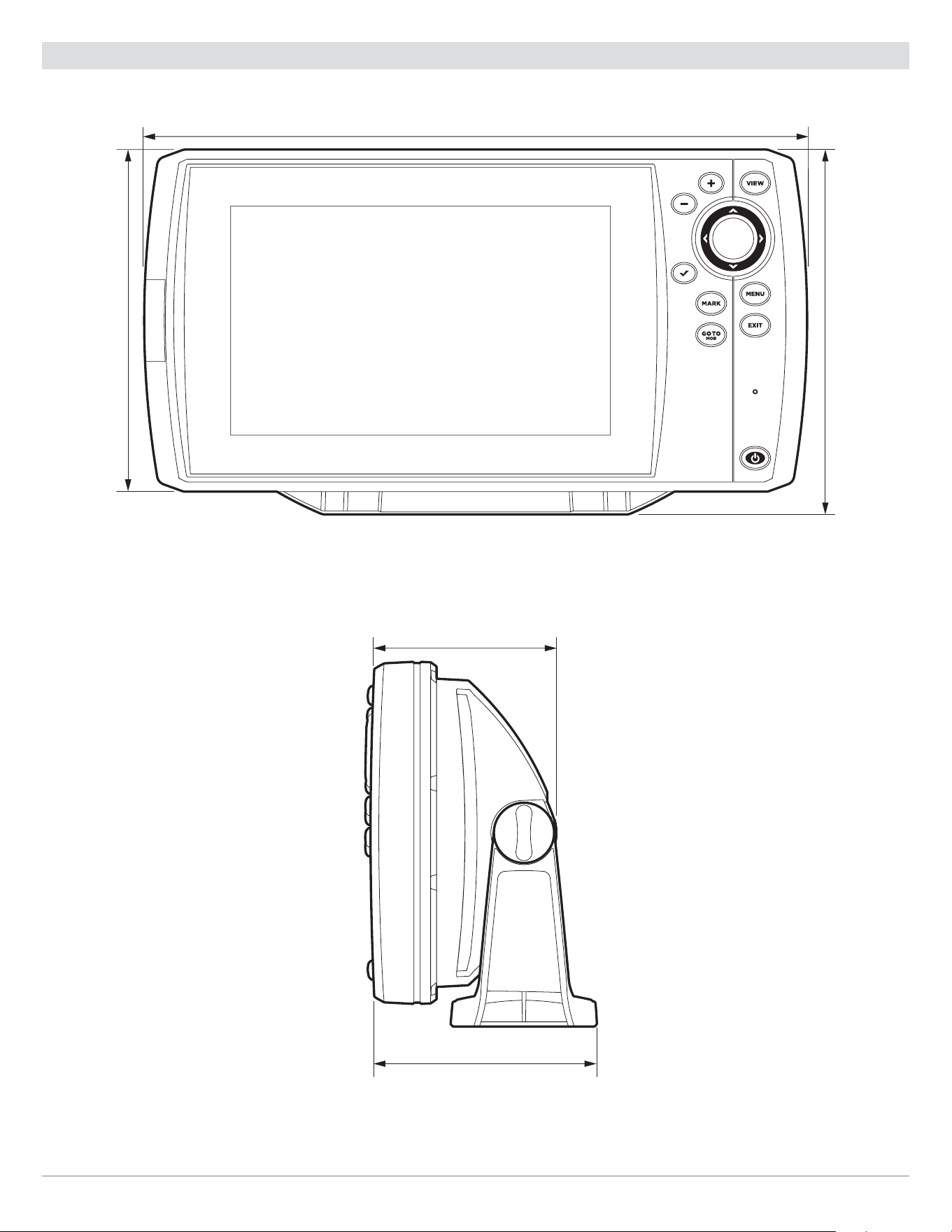
273
Specifications
HELIX 7 G2/G2N, G3/G3N and G4 Control Head Measurements
HELIX 7 G2/G2N, G3/G3N and G4 Gimbal Mount
10.54 in (267.72 mm)
5.44 in
(138.18 mm)
5.80 in
(147.32 mm)
2.97 in (75.44 mm)
3.60 in (91.44 mm)
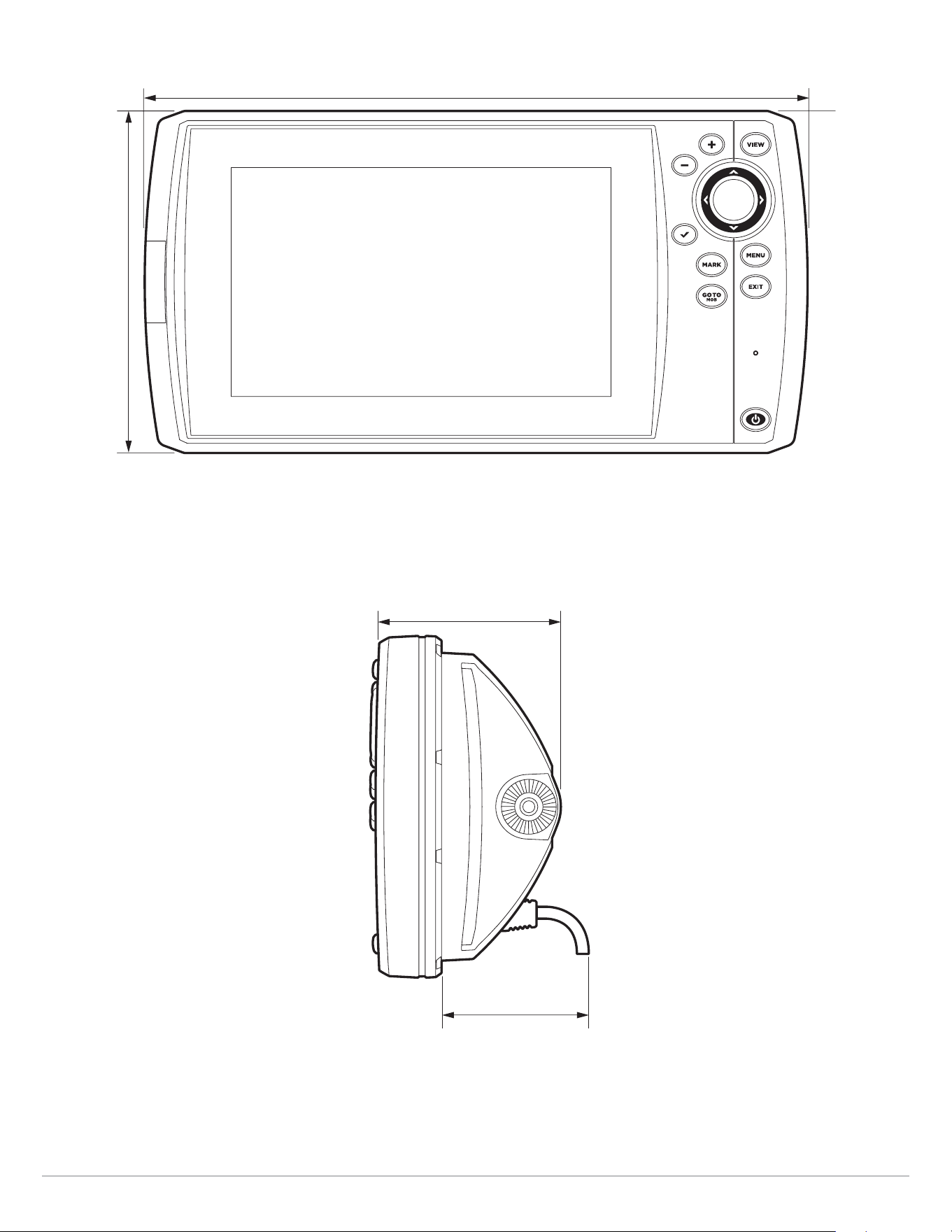
274
Specifications
HELIX 7 G2/G2N, G3/G3N and G4 In-Dash Mount
10.54 in (267.72 mm)
5.44 in
(138.18 mm)
2.17 in (55.12 mm)
2.97 in (75.44 mm)

275
Specifications
HELIX 7 CHIRP GPS G4N
Control Head
Display Size (diagonal) ................................................................................... 7 inches (178 mm)
Pixel Matrix ............................................................................................ WSVGA 600V x 1024H
Display Type ...................................................................................................... TFT Color
Backlight .............................................................................................................. LED
Communication .......................................................... Bluetooth, NMEA 0183, NMEA 2000, Ethernet, Wireless
Power Input ................................................................................................... 10 to 20 VDC
Current Draw ....................................................................................................... 950 mA
IPX Rating ................................................................. IPX7 Waterproof/Submersible @ 1 m for 30 minutes
Bluetooth Frequency Range ................................................................................ 2402 to 2480 MHz
Bluetooth Output Power ...................................................................................... 10 dBm Typical
Dual Spectrum 2D CHIRP Transducer
XNT 9 HW T (includes built-in temperature probe)
Default Operating Frequency ............................................................................... 150 kHz - 220 kHz
Depth Capability ............................................................................................ 1000 ft (305 m)
Area of Coverage ............................................................................ Full: 42°@-10 dB in 150-220 kHz
Wide: 42°@-10 dB in 140-200 kHz
Narrow: 25°@-10 dB in 180-240 kHz
Power Output (MAX) .............................................................. 500 Watts (RMS), 4000 Watts (Peak to Peak)
NOTE: Humminbird verifies maximum stated depth in saltwater conditions, but actual depth performance may vary due to
transducer installation, water type, thermal layers, bottom composition, and slope.
NOTE: Product specifications and features are subject to change without notice.

276
Specifications
HELIX 7 CHIRP MEGA DI GPS G4N
Control Head
Display Size (diagonal) ................................................................................... 7 inches (178 mm)
Pixel Matrix ............................................................................................ WSVGA 600V x 1024H
Display Type ...................................................................................................... TFT Color
Backlight .............................................................................................................. LED
Communication .......................................................... Bluetooth, NMEA 0183, NMEA 2000, Ethernet, Wireless
Power Input ................................................................................................... 10 to 20 VDC
Current Draw ....................................................................................................... 950 mA
IPX Rating ................................................................. IPX7 Waterproof/Submersible @ 1 m for 30 minutes
Bluetooth Frequency Range ................................................................................ 2402 to 2480 MHz
Bluetooth Output Power ...................................................................................... 10 dBm Typical
CHIRP MEGA Down Imaging Transducer
XNT 9 HW MDI 75 T (includes built-in temperature probe)
Down Imaging
Operating Frequency ......................................................................................... 455 kHz, MEGA
Depth Capability ..................................................................................... 455 kHz: 350 ft (107 m)
MEGA: 125 ft (38 m)
Area of Coverage ............................................................................455 kHz: 75° @ -10 dB in 455 kHz
MEGA: 75° @ -10 dB in MEGA kHz
Power Output (MAX) .............................................................. 500 Watts (RMS), 4000 Watts (Peak to Peak)
Dual Spectrum
Default Operating Frequency ............................................................................... 150 kHz - 220 kHz
Depth Capability ............................................................................................ 1000 ft (305 m)
Area of Coverage ............................................................................ Full: 42°@-10 dB in 150-220 kHz
Wide: 42°@-10 dB in 140-200 kHz
Narrow: 25°@-10 dB in 180-240 kHz
Power Output (MAX) .............................................................. 500 Watts (RMS), 4000 Watts (Peak to Peak)
NOTE: Humminbird verifies maximum stated depth in saltwater conditions, but actual depth performance may vary due to
transducer installation, water type, thermal layers, bottom composition, and slope.
NOTE: Product specifications and features are subject to change without notice

277
Specifications
HELIX 7 CHIRP MEGA SI GPS G4N
Control Head
Display Size (diagonal) ................................................................................... 7 inches (178 mm)
Pixel Matrix ............................................................................................ WSVGA 600V x 1024H
Display Type ...................................................................................................... TFT Color
Backlight .............................................................................................................. LED
Communication .......................................................... Bluetooth, NMEA 0183, NMEA 2000, Ethernet, Wireless
Power Input ................................................................................................... 10 to 20 VDC
Current Draw ....................................................................................................... 950 mA
IPX Rating ................................................................. IPX7 Waterproof/Submersible @ 1 m for 30 minutes
Bluetooth Frequency Range ................................................................................ 2402 to 2480 MHz
Bluetooth Output Power ...................................................................................... 10 dBm Typical
CHIRP MEGA Side Imaging Transducer
XNT 9 HW MSI 150 T (includes built-in temperature probe)
Side Imaging
Operating Frequency ......................................................................................... 455 kHz, MEGA
Depth Capability ..................................................................................... 455 kHz: 480 ft (146 m)
MEGA: 250 ft (76 m)
Area of Coverage ........................................................................... 455 kHz: 75° @ -10 dB in 455 kHz
MEGA: 75° @ -10 dB in MEGA kHz
Power Output (MAX) .............................................................. 500 Watts (RMS), 4000 Watts (Peak to Peak)
Down Imaging
Operating Frequency ......................................................................................... 455 kHz, MEGA
Depth Capability ...................................................................................... 455 kHz: 125 ft (38 m)
MEGA: 75 ft (23 m)
Area of Coverage ........................................................................... 455 kHz: 75° @ -10 dB in 455 kHz
MEGA: 75° @ -10 dB in MEGA kHz
Power Output (MAX) .............................................................. 500 Watts (RMS), 4000 Watts (Peak to Peak)

278
Specifications
Dual Spectrum
Default Operating Frequency ............................................................................... 150 kHz - 220 kHz
Depth Capability ............................................................................................ 1000 ft (305 m)
Area of Coverage ............................................................................ Full: 42°@-10 dB in 150-220 kHz
Wide: 42°@-10 dB in 140-200 kHz
Narrow: 25°@-10 dB in 180-240 kHz
Power Output (MAX) .............................................................. 500 Watts (RMS), 4000 Watts (Peak to Peak)
NOTE: Humminbird verifies maximum stated depth in saltwater conditions, but actual depth performance may vary due to
transducer installation, water type, thermal layers, bottom composition, and slope.
NOTE: Product specifications and features are subject to change without notice.
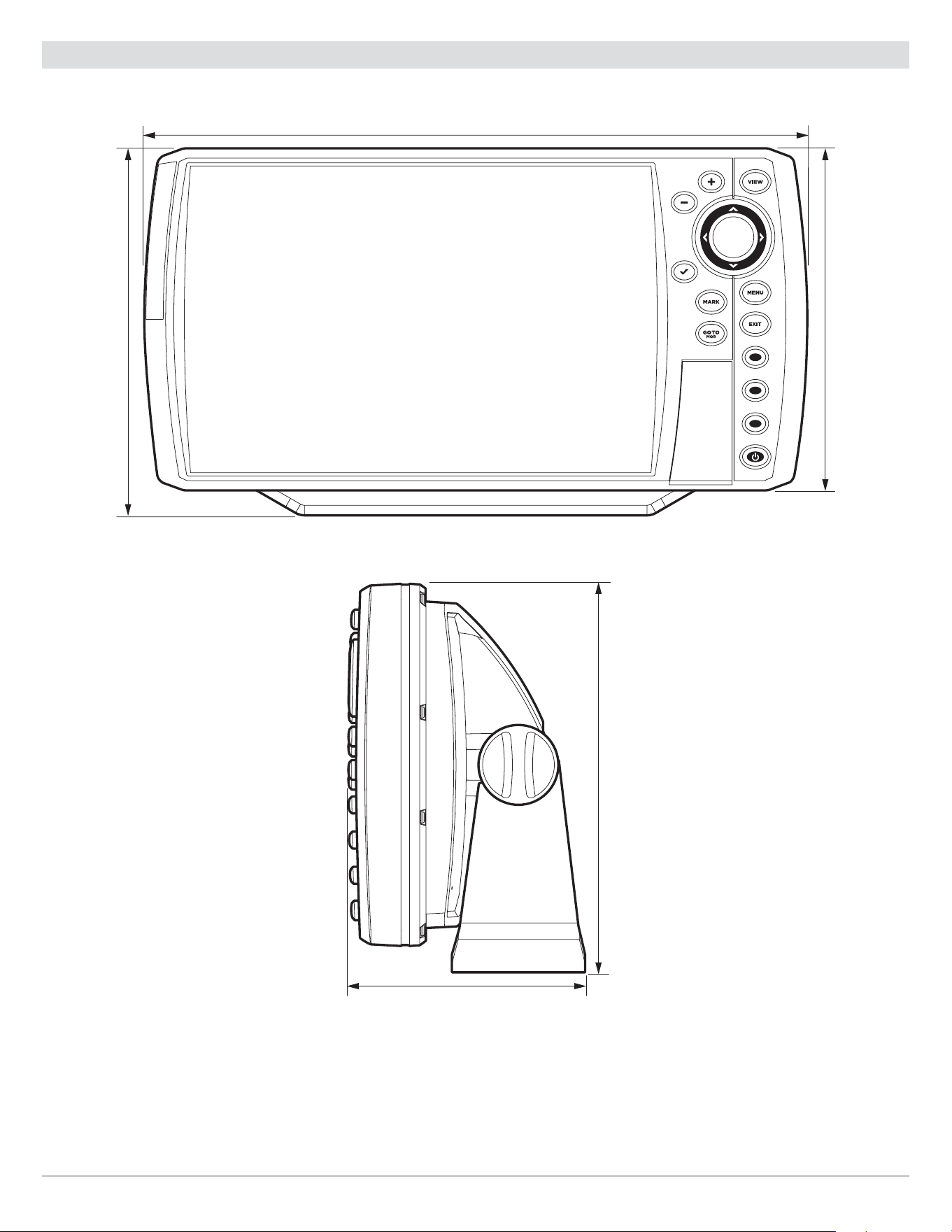
279
Specifications
HELIX 7 G4N Control Head Measurements
HELIX 7 G4N Gimbal Mount
10.54 in (267.71 mm)
5.84 in
(148.46 mm)
5.44 in
(138.14 mm)
3.55
||
(90.24 mm)
5.84
||
(148.46 mm)
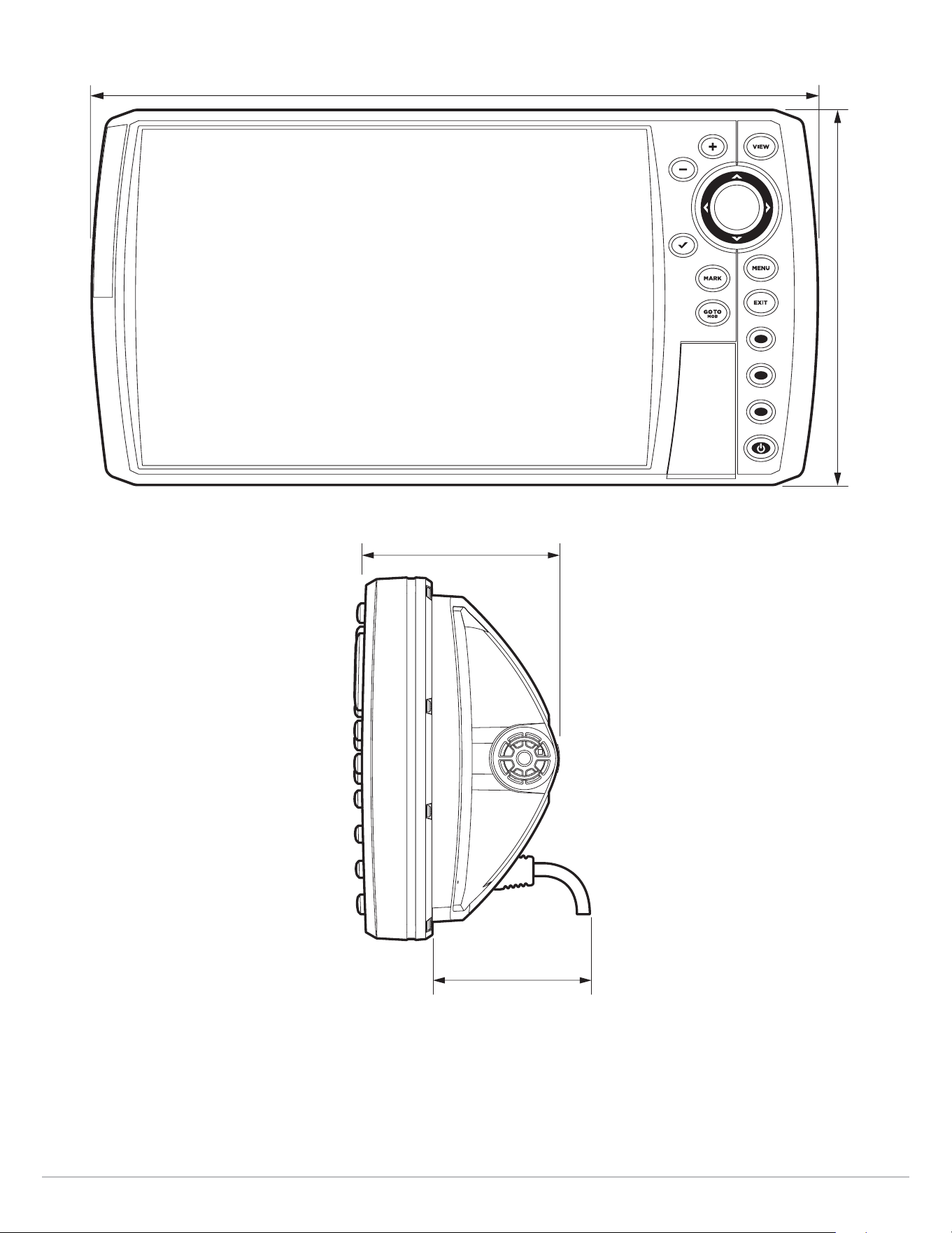
280
Specifications
HELIX 7 G4N In-Dash Mount
10.54 in (267.71 mm)
5.44 in
(138.14 mm)
2.17
||
(55.12 mm)
2.97
||
(75.44 mm)

281
Specifications
HELIX 8 CHIRP GPS G3N
Control Head
Display Size (diagonal) ................................................................................... 8 inches (203 mm)
Pixel Matrix ............................................................................................. WVGA 600V x 1024H
Display Type ...................................................................................................... TFT Color
Backlight .............................................................................................................. LED
Communication ........................................................................................ NMEA 0183, Ethernet
Power Input ................................................................................................... 10 to 20 VDC
Current Draw ......................................................................................................... 1.8 A
IPX Rating ................................................................. IPX7 Waterproof/Submersible @ 1 m for 30 minutes
Bluetooth Frequency Range ................................................................................ 2402 to 2480 MHz
Bluetooth Output Power ...................................................................................... 10 dBm Typical
Dual Spectrum 2D CHIRP Transducer
XNT 9 HW T (includes built-in temperature probe)
Default Operating Frequency ............................................................................... 150 kHz - 220 kHz
Depth Capability ............................................................................................ 1000 ft (305 m)
Area of Coverage ............................................................................ Full: 42°@-10 dB in 150-220 kHz
Wide: 42°@-10 dB in 140-200 kHz
Narrow: 25°@-10 dB in 180-240 kHz
Power Output (MAX) .............................................................. 500 Watts (RMS), 4000 Watts (Peak to Peak)
NOTE: Humminbird verifies maximum stated depth in saltwater conditions, but actual depth performance may vary due to
transducer installation, water type, thermal layers, bottom composition, and slope.
NOTE: Product specifications and features are subject to change without notice.

282
Specifications
HELIX 8 CHIRP MEGA DI GPS G3N
Control Head
Display Size (diagonal) ................................................................................... 8 inches (203 mm)
Pixel Matrix ............................................................................................. WVGA 600V x 1024H
Display Type ...................................................................................................... TFT Color
Backlight .............................................................................................................. LED
Communication ........................................................................................ NMEA 0183, Ethernet
Power Input ................................................................................................... 10 to 20 VDC
Current Draw ......................................................................................................... 1.8 A
IPX Rating ................................................................. IPX7 Waterproof/Submersible @ 1 m for 30 minutes
Bluetooth Frequency Range ................................................................................ 2402 to 2480 MHz
Bluetooth Output Power ...................................................................................... 10 dBm Typical
CHIRP MEGA Down Imaging Transducer
XNT 9 HW MDI 75 T (includes built-in temperature probe)
Down Imaging
Operating Frequency ......................................................................................... 455 kHz, MEGA
Depth Capability ..................................................................................... 455 kHz: 350 ft (107 m)
MEGA: 125 ft (38 m)
Area of Coverage ............................................................................455 kHz: 75° @ -10 dB in 455 kHz
MEGA: 75° @ -10 dB in MEGA kHz
Power Output (MAX) .............................................................. 500 Watts (RMS), 4000 Watts (Peak to Peak)
Dual Spectrum
Default Operating Frequency ............................................................................... 150 kHz - 220 kHz
Depth Capability ............................................................................................ 1000 ft (305 m)
Area of Coverage ............................................................................ Full: 42°@-10 dB in 150-220 kHz
Wide: 42°@-10 dB in 140-200 kHz
Narrow: 25°@-10 dB in 180-240 kHz
Power Output (MAX) .............................................................. 500 Watts (RMS), 4000 Watts (Peak to Peak)
NOTE: Humminbird verifies maximum stated depth in saltwater conditions, but actual depth performance may vary due to
transducer installation, water type, thermal layers, bottom composition, and slope.
NOTE: Product specifications and features are subject to change without notice.

283
Specifications
HELIX 8 CHIRP MEGA SI+GPS G3N
Control Head
Display Size (diagonal) ................................................................................... 8 inches (203 mm)
Pixel Matrix ............................................................................................. WVGA 600V x 1024H
Display Type ...................................................................................................... TFT Color
Backlight .............................................................................................................. LED
Communication ........................................................................................ NMEA 0183, Ethernet
Power Input ................................................................................................... 10 to 20 VDC
Current Draw ......................................................................................................... 1.8 A
IPX Rating ................................................................. IPX7 Waterproof/Submersible @ 1 m for 30 minutes
Bluetooth Frequency Range ................................................................................ 2402 to 2480 MHz
Bluetooth Output Power ...................................................................................... 10 dBm Typical
CHIRP MEGA Side Imaging+ Transducer
XM 9 HW MSI T (includes built-in temperature probe)
Side Imaging
Operating Frequency ................................................................................. 455 kHz, 800 kHz, MEGA
Depth Capability ..................................................................................... 455 kHz: 800 ft (244 m)
800 kHz: 250 ft (76 m)
MEGA: 400 ft (122 m)
Area of Coverage ........................................................................... 455 kHz: 86° @ -10 dB in 455 kHz
800 kHz: 86° @ -10 dB in 800 kHz
MEGA: 86° @ -10 dB in MEGA kHz
Power Output (MAX) .............................................................. 500 Watts (RMS), 4000 Watts (Peak to Peak)
Down Imaging
Operating Frequency ................................................................................. 455 kHz, 800 kHz, MEGA
Depth Capability ..................................................................................... 455 kHz: 400 ft (122 m)
800 kHz: 125 ft (38 m)
MEGA: 200 ft (61 m)
Area of Coverage ........................................................................... 455 kHz: 75° @ -10 dB in 455 kHz
800 kHz: 45° @ -10 dB in 800 kHz
MEGA: 75° @ -10 dB in MEGA kHz
Power Output (MAX) .............................................................. 500 Watts (RMS), 4000 Watts (Peak to Peak)

284
Specifications
Dual Spectrum
Default Operating Frequency ............................................................................... 150 kHz - 220 kHz
Depth Capability ............................................................................................ 1000 ft (305 m)
Area of Coverage ............................................................................ Full: 42°@-10 dB in 150-220 kHz
Wide: 42°@-10 dB in 140-200 kHz
Narrow: 25°@-10 dB in 180-240 kHz
Power Output (MAX) .............................................................. 500 Watts (RMS), 4000 Watts (Peak to Peak)
NOTE: Humminbird verifies maximum stated depth in saltwater conditions, but actual depth performance may vary due to
transducer installation, water type, thermal layers, bottom composition, and slope.
NOTE: Product specifications and features are subject to change without notice.

285
Specifications
HELIX 8 CHIRP GPS G4N
Control Head
Display Size (diagonal) ................................................................................... 8 inches (203 mm)
Pixel Matrix ............................................................................................ WSVGA 600V x 1024H
Display Type ...................................................................................................... TFT Color
Backlight .............................................................................................................. LED
Communication .......................................................... Bluetooth, NMEA 0183, NMEA 2000, Ethernet, Wireless
Power Input ................................................................................................... 10 to 20 VDC
Current Draw ......................................................................................................... 1.8 A
IPX Rating ................................................................. IPX7 Waterproof/Submersible @ 1 m for 30 minutes
Bluetooth Frequency Range ................................................................................ 2402 to 2480 MHz
Bluetooth Output Power ...................................................................................... 10 dBm Typical
Dual Spectrum 2D CHIRP Transducer
XNT 9 HW T (includes built-in temperature probe)
Default Operating Frequency ............................................................................... 150 kHz - 220 kHz
Depth Capability ............................................................................................ 1200 ft (366 m)
Area of Coverage ............................................................................ Full: 42°@-10 dB in 150-220 kHz
Wide: 42°@-10 dB in 140-200 kHz
Narrow: 25°@-10 dB in 180-240 kHz
Power Output (MAX) .............................................................. 500 Watts (RMS), 4000 Watts (Peak to Peak)
NOTE: Humminbird verifies maximum stated depth in saltwater conditions, but actual depth performance may vary due to
transducer installation, water type, thermal layers, bottom composition, and slope.
NOTE: Product specifications and features are subject to change without notice.

286
Specifications
HELIX 8 CHIRP MEGA DI GPS G4N
Control Head
Display Size (diagonal) ................................................................................... 8 inches (203 mm)
Pixel Matrix ............................................................................................ WSVGA 600V x 1024H
Display Type ...................................................................................................... TFT Color
Backlight .............................................................................................................. LED
Communication .......................................................... Bluetooth, NMEA 0183, NMEA 2000, Ethernet, Wireless
Power Input ................................................................................................... 10 to 20 VDC
Current Draw ......................................................................................................... 1.8 A
IPX Rating ................................................................. IPX7 Waterproof/Submersible @ 1 m for 30 minutes
Bluetooth Frequency Range ................................................................................ 2402 to 2480 MHz
Bluetooth Output Power ...................................................................................... 10 dBm Typical
CHIRP MEGA Down Imaging Transducer
XNT 9 HW MDI 75 T (includes built-in temperature probe)
Down Imaging
Operating Frequency ......................................................................................... 455 kHz, MEGA
Depth Capability ..................................................................................... 455 kHz: 350 ft (107 m)
MEGA: 125 ft (38 m)
Area of Coverage ............................................................................455 kHz: 75° @ -10 dB in 455 kHz
MEGA: 75° @ -10 dB in MEGA kHz
Power Output (MAX) .............................................................. 500 Watts (RMS), 4000 Watts (Peak to Peak)
Dual Spectrum
Default Operating Frequency ............................................................................... 150 kHz - 220 kHz
Depth Capability ............................................................................................ 1200 ft (366 m)
Area of Coverage ............................................................................ Full: 42°@-10 dB in 150-220 kHz
Wide: 42°@-10 dB in 140-200 kHz
Narrow: 25°@-10 dB in 180-240 kHz
Power Output (MAX) .............................................................. 500 Watts (RMS), 4000 Watts (Peak to Peak)
NOTE: Humminbird verifies maximum stated depth in saltwater conditions, but actual depth performance may vary due to
transducer installation, water type, thermal layers, bottom composition, and slope.
NOTE: Product specifications and features are subject to change without notice.

287
Specifications
HELIX 8 CHIRP MEGA SI+GPS G4N
Control Head
Display Size (diagonal) ................................................................................... 8 inches (203 mm)
Pixel Matrix ............................................................................................ WSVGA 600V x 1024H
Display Type ...................................................................................................... TFT Color
Backlight .............................................................................................................. LED
Communication .......................................................... Bluetooth, NMEA 0183, NMEA 2000, Ethernet, Wireless
Power Input ................................................................................................... 10 to 20 VDC
Current Draw ......................................................................................................... 1.8 A
IPX Rating ................................................................. IPX7 Waterproof/Submersible @ 1 m for 30 minutes
Bluetooth Frequency Range ................................................................................ 2402 to 2480 MHz
Bluetooth Output Power ...................................................................................... 10 dBm Typical
CHIRP MEGA Side Imaging+ Transducer
XM 9 HW MSI T (includes built-in temperature probe)
Side Imaging
Operating Frequency ................................................................................. 455 kHz, 800 kHz, MEGA
Depth Capability ..................................................................................... 455 kHz: 800 ft (244 m)
800 kHz: 250 ft (76 m)
MEGA: 400 ft (122 m)
Area of Coverage ........................................................................... 455 kHz: 86° @ -10 dB in 455 kHz
800 kHz: 86° @ -10 dB in 800 kHz
MEGA: 86° @ -10 dB in MEGA kHz
Power Output (MAX) .............................................................. 500 Watts (RMS), 4000 Watts (Peak to Peak)
Down Imaging
Operating Frequency ................................................................................. 455 kHz, 800 kHz, MEGA
Depth Capability ..................................................................................... 455 kHz: 400 ft (122 m)
800 kHz: 125 ft (38 m)
MEGA: 200 ft (61 m)
Area of Coverage ........................................................................... 455 kHz: 75° @ -10 dB in 455 kHz
800 kHz: 45° @ -10 dB in 800 kHz
MEGA: 75° @ -10 dB in MEGA kHz
Power Output (MAX) .............................................................. 500 Watts (RMS), 4000 Watts (Peak to Peak)

288
Specifications
Dual Spectrum
Default Operating Frequency ............................................................................... 150 kHz - 220 kHz
Depth Capability ............................................................................................ 1200 ft (366 m)
Area of Coverage ............................................................................ Full: 42°@-10 dB in 150-220 kHz
Wide: 42°@-10 dB in 140-200 kHz
Narrow: 25°@-10 dB in 180-240 kHz
Power Output (MAX) .............................................................. 500 Watts (RMS), 4000 Watts (Peak to Peak)
NOTE: Humminbird verifies maximum stated depth in saltwater conditions, but actual depth performance may vary due to
transducer installation, water type, thermal layers, bottom composition, and slope.
NOTE: Product specifications and features are subject to change without notice.
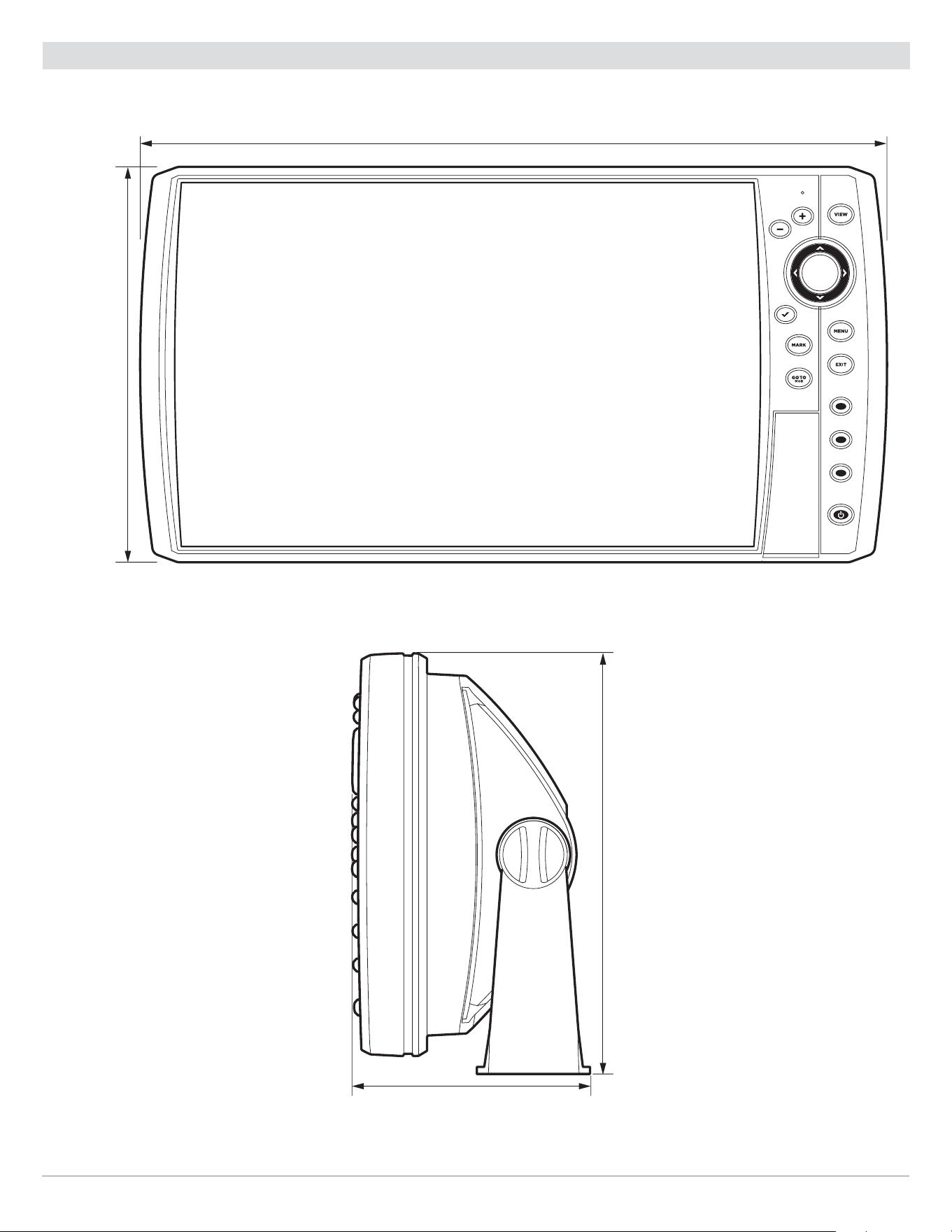
289
Specifications
HELIX 8 Control Head Measurements
HELIX 8 Gimbal Mount
11.998
||
(304.75 mm)
6.623
||
(168.22 mm)
4.103
||
(104.22 mm)
7.251
||
(184.18 mm)
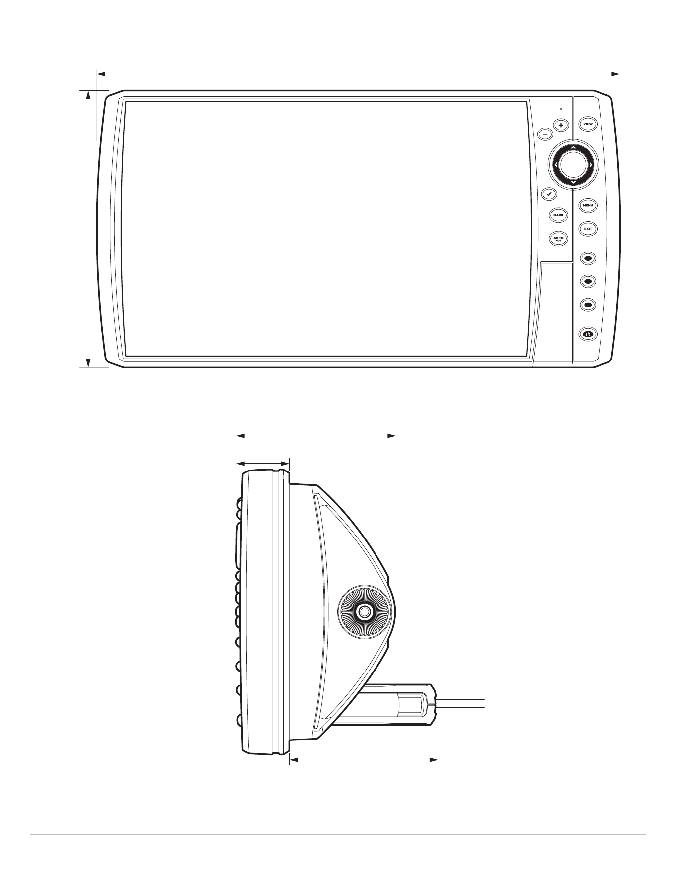
290
Specifications
HELIX 8 In-Dash Mount
11.998
||
(304.75 mm)
6.623
||
(168.22 mm)
3.674
||
(93.32 mm)
3.938
||
(100.03 mm)
1.220
||
(30.99 mm)

291
Specifications
HELIX 9 CHIRP GPS G2N
Control Head
Display Size (diagonal) ................................................................................. 9 inches (228.6 mm)
Pixel Matrix .............................................................................................. WVGA 480V x 800H
Display Type ...................................................................................................... TFT Color
Backlight .............................................................................................................. LED
Communication ........................................................................................ NMEA 0183, Ethernet
Power Input ................................................................................................... 10 to 20 VDC
Current Draw ......................................................................................................... 1.3 A
IPX Rating ................................................................. IPX7 Waterproof/Submersible @ 1 m for 30 minutes
Bluetooth Frequency Range ................................................................................ 2402 to 2480 MHz
Bluetooth Output Power ...................................................................................... 10 dBm Typical
CHIRP DualBeam PLUS Transducer
XNT 9 20 T (includes built-in temperature probe)
Operating Frequency ........................................................................................ 200 kHz, 83 kHz
Depth Capability ............................................................................................ 1500 ft (457 m)
Area of Coverage ............................................................... 60°@-10 dB in 83 kHz, 20°@-10 dB in 200 kHz
Power Output (MAX) .............................................................. 500 Watts (RMS), 4000 Watts (Peak to Peak)
NOTE: Humminbird verifies maximum stated depth in saltwater conditions, but actual depth performance may vary due to
transducer installation, water type, thermal layers, bottom composition, and slope.
NOTE: Product specifications and features are subject to change without notice.

292
Specifications
HELIX 9 CHIRP DI GPS G2N
Control Head
Display Size (diagonal) ................................................................................. 9 inches (228.6 mm)
Pixel Matrix .............................................................................................. WVGA 480V x 800H
Display Type ...................................................................................................... TFT Color
Backlight .............................................................................................................. LED
Communication ........................................................................................ NMEA 0183, Ethernet
Power Input ................................................................................................... 10 to 20 VDC
Current Draw ......................................................................................................... 2.5 A
IPX Rating ................................................................. IPX7 Waterproof/Submersible @ 1 m for 30 minutes
Bluetooth Frequency Range ................................................................................ 2402 to 2480 MHz
Bluetooth Output Power ...................................................................................... 10 dBm Typical
CHIRP Down Imaging Transducer
XNT 9 DI T (includes built-in temperature probe)
Down Imaging
Operating Frequency ....................................................................................... 455 kHz, 800 kHz
Depth Capability ............................................................................................. 350 ft (107 m)
Area of Coverage .............................................................75º @ -10 dB in 455 kHz, 45º @ -10 dB in 800 kHz
Power Output (MAX) .............................................................. 500 Watts (RMS), 4000 Watts (Peak to Peak)
DualBeam PLUS
Operating Frequency ....................................................................................... 200 kHz, 455 kHz
Depth Capability ..............................................................................................600 ft (183 m)
Area of Coverage .............................................................28° @ -10 dB in 200 kHz, 16° @ -10 dB in 455 kHz
Power Output (MAX) ...............................................................500 Watts (RMS), 4000 Watts (Peak to Peak)
NOTE: Humminbird verifies maximum stated depth in saltwater conditions, but actual depth performance may vary due to
transducer installation, water type, thermal layers, bottom composition, and slope.
NOTE: Product specifications and features are subject to change without notice.

293
Specifications
HELIX 9 CHIRP DI GPS G2N (CHIRP MEGA DI)
Control Head
Display Size (diagonal) ................................................................................. 9 inches (228.6 mm)
Pixel Matrix .............................................................................................. WVGA 480V x 800H
Display Type ...................................................................................................... TFT Color
Backlight .............................................................................................................. LED
Communication ........................................................................................ NMEA 0183, Ethernet
Power Input ................................................................................................... 10 to 20 VDC
Current Draw ......................................................................................................... 1.3 A
IPX Rating ................................................................. IPX7 Waterproof/Submersible @ 1 m for 30 minutes
Bluetooth Frequency Range ................................................................................ 2402 to 2480 MHz
Bluetooth Output Power ...................................................................................... 10 dBm Typical
CHIRP MEGA Down Imaging Transducer
XM 9 MDI T (includes built-in temperature probe)
Down Imaging
Operating Frequency ................................................................................. 455 kHz, 800 kHz, MEGA
Depth Capability ..................................................................................... 455 kHz: 400 ft (122 m)
800 kHz: 125 ft (38 m)
MEGA: 125 ft (38 m)
Area of Coverage .................................................................................... 75° @ -10 dB in 455 kHz
45° @ -10 dB in 800 kHz
MEGA: 75° @ -10 dB in MEGA kHz
Power Output (MAX) .............................................................. 500 Watts (RMS), 4000 Watts (Peak to Peak)
Dual Spectrum
Default Operating Frequency ............................................................................... 150 kHz - 220 kHz
Depth Capability ............................................................................................ 1000 ft (305 m)
Area of Coverage ............................................................................ Full: 42°@-10 dB in 150-220 kHz
Wide: 42°@-10 dB in 140-200 kHz
Narrow: 25°@-10 dB in 180-240 kHz
Power Output (MAX) .............................................................. 500 Watts (RMS), 4000 Watts (Peak to Peak)
NOTE: Humminbird verifies maximum stated depth in saltwater conditions, but actual depth performance may vary due to
transducer installation, water type, thermal layers, bottom composition, and slope.
NOTE: Product specifications and features are subject to change without notice.

294
Specifications
HELIX 9 CHIRP SI GPS G2N (CHIRP MEGA SI)
Control Head
Display Size (diagonal) ................................................................................. 9 inches (228.6 mm)
Pixel Matrix .............................................................................................. WVGA 480V x 800H
Display Type ...................................................................................................... TFT Color
Backlight .............................................................................................................. LED
Communication ........................................................................................ NMEA 0183, Ethernet
Power Input ................................................................................................... 10 to 20 VDC
Current Draw ......................................................................................................... 2.5 A
IPX Rating ................................................................. IPX7 Waterproof/Submersible @ 1 m for 30 minutes
Bluetooth Frequency Range ................................................................................ 2402 to 2480 MHz
Bluetooth Output Power ...................................................................................... 10 dBm Typical
CHIRP MEGA Side Imaging Transducer
XM 9 20 MSI T (includes built-in temperature probe)
Side Imaging
Operating Frequency ................................................................................. 455 kHz, 800 kHz, MEGA
Range Capability ......................................................................... 455 kHz: 800 ft (244 m) Side to Side
800 kHz: 250 ft (76 m) Side to Side
MEGA: 250 ft (76 m) Side to Side
Area of Coverage ............................................................ (2) 86º @ -10 dB in 455 kHz (180º Total Coverage)
(2) 55º @ -10 dB in 800 kHz (130º Total Coverage)
MEGA: (2) 86º @ -10 dB in MEGA kHz (180º Total Coverage)
Power Output (MAX) .............................................................. 500 Watts (RMS), 4000 Watts (Peak to Peak)
Down Imaging
Operating Frequency ................................................................................. 455 kHz, 800 kHz, MEGA
Depth Capability ..................................................................................... 455 kHz: 400 ft (122 m)
800 kHz: 125 ft (38 m)
MEGA: 125 ft (38 m)
Area of Coverage .................................................................................... 75° @ -10 dB in 455 kHz
45° @ -10 dB in 800 kHz
MEGA: 75° @ -10 dB in MEGA kHz
Power Output (MAX) .............................................................. 500 Watts (RMS), 4000 Watts (Peak to Peak)

295
Specifications
DualBeam PLUS
Operating Frequency ........................................................................................ 200 kHz, 83 kHz
Depth Capability ............................................................................................ 1500 ft (457 m)
Area of Coverage ..................................................................................... 60° @ -10 dB in 83 kHz,
20° @ -10 dB in 200 kHz
Power Output (MAX) .............................................................. 500 Watts (RMS), 4000 Watts (Peak to Peak)
NOTE: Humminbird verifies maximum stated depth in saltwater conditions, but actual depth performance may vary due to
transducer installation, water type, thermal layers, bottom composition, and slope.
NOTE: Product specifications and features are subject to change without notice.
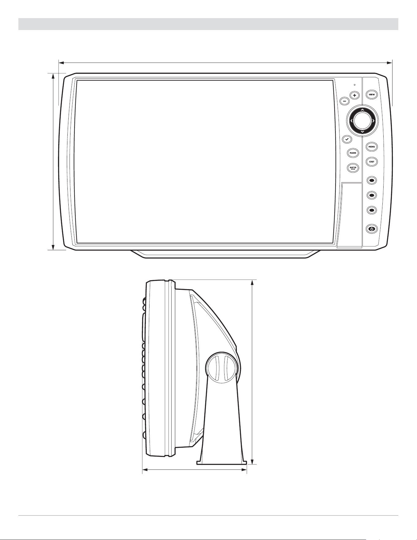
296
Specifications
HELIX 9 G2N Control Head Measurements
HELIX 9 G2N Gimbal Mount
13.44
||
(341.38 mm)
7.114
||
(180.7 mm)
4.203
||
(106.76 mm)
7.5
||
(191 mm)
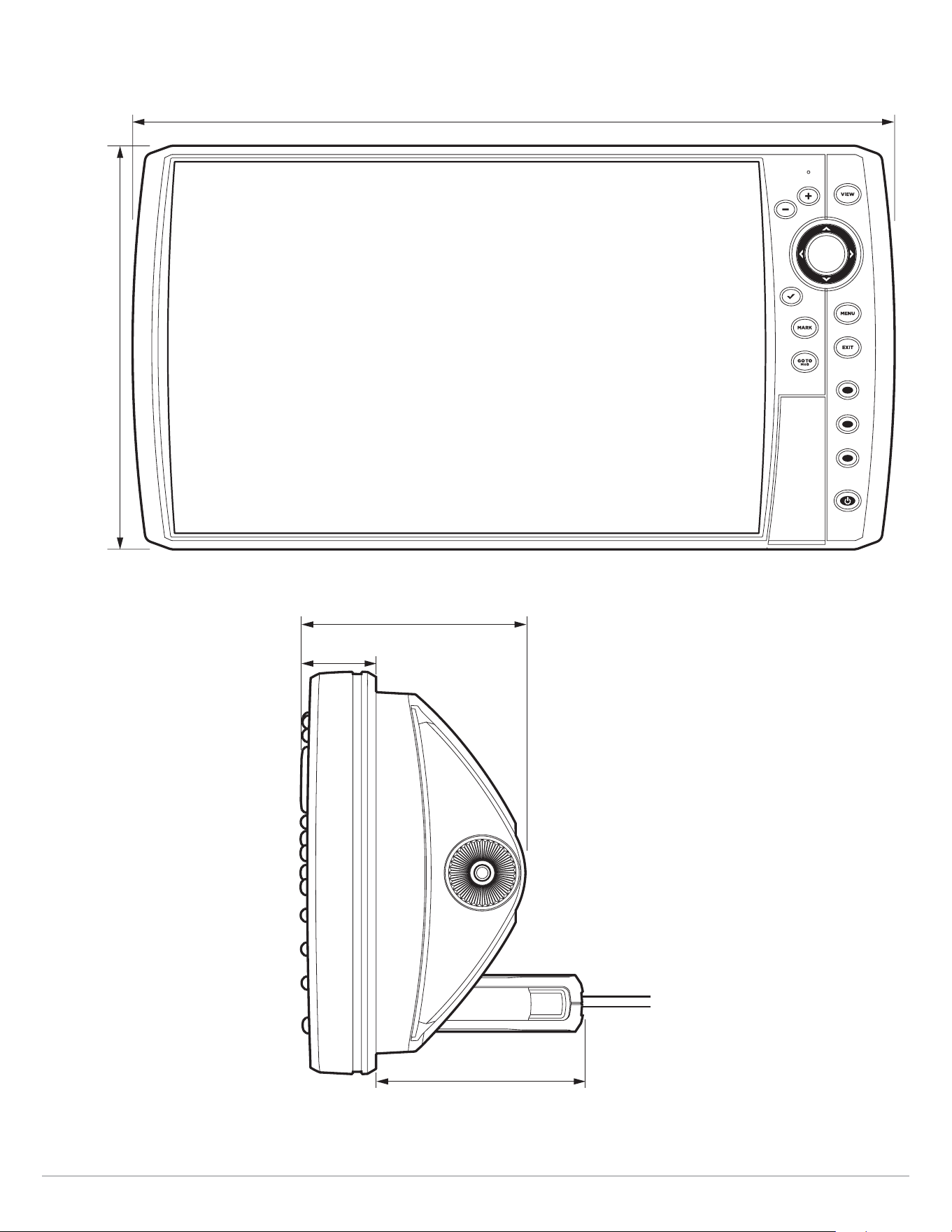
297
Specifications
HELIX 9 G2N In-Dash Mount
13.44
||
(341.38 mm)
7.114
||
(180.7 mm)
3.685
||
(93.59 mm)
3.991
||
(101.37 mm)
1.324
||
(33.63 mm)

298
Specifications
HELIX 9 CHIRP GPS G3N
Control Head
Display Size (diagonal) ................................................................................. 9 inches (228.6 mm)
Pixel Matrix ............................................................................................. WVGA 600V x 1024H
Display Type ...................................................................................................... TFT Color
Backlight .............................................................................................................. LED
Communication ........................................................................................ NMEA 0183, Ethernet
Power Input ................................................................................................... 10 to 20 VDC
Current Draw ......................................................................................................... 1.9 A
IPX Rating ................................................................. IPX7 Waterproof/Submersible @ 1 m for 30 minutes
Bluetooth Frequency Range ................................................................................ 2402 to 2480 MHz
Bluetooth Output Power ...................................................................................... 10 dBm Typical
Dual Spectrum 2D CHIRP Transducer
XNT 9 HW T (includes built-in temperature probe)
Default Operating Frequency ............................................................................... 150 kHz - 220 kHz
Depth Capability ............................................................................................ 1000 ft (305 m)
Area of Coverage ............................................................................ Full: 42°@-10 dB in 150-220 kHz
Wide: 42°@-10 dB in 140-200 kHz
Narrow: 25°@-10 dB in 180-240 kHz
Power Output (MAX) .............................................................. 500 Watts (RMS), 4000 Watts (Peak to Peak)
NOTE: Humminbird verifies maximum stated depth in saltwater conditions, but actual depth performance may vary due to
transducer installation, water type, thermal layers, bottom composition, and slope.
NOTE: Product specifications and features are subject to change without notice.

299
Specifications
HELIX 9 CHIRP MEGA DI+ GPS G3N
Control Head
Display Size (diagonal) ................................................................................. 9 inches (228.6 mm)
Pixel Matrix ............................................................................................. WVGA 600V x 1024H
Display Type ...................................................................................................... TFT Color
Backlight .............................................................................................................. LED
Communication ........................................................................................ NMEA 0183, Ethernet
Power Input ................................................................................................... 10 to 20 VDC
Current Draw ......................................................................................................... 1.9 A
IPX Rating ................................................................. IPX7 Waterproof/Submersible @ 1 m for 30 minutes
Bluetooth Frequency Range ................................................................................ 2402 to 2480 MHz
Bluetooth Output Power ...................................................................................... 10 dBm Typical
CHIRP MEGA Down Imaging+ Transducer
XM 9 HW MDI T (includes built-in temperature probe)
Down Imaging
Operating Frequency ................................................................................. 455 kHz, 800 kHz, MEGA
Depth Capability ..................................................................................... 455 kHz: 400 ft (122 m)
800 kHz: 125 ft (38m)
MEGA: 200 ft (61 m)
Area of Coverage ............................................................................455 kHz: 75° @ -10 dB in 455 kHz
800 kHz: 45° @ -10 dB in 800 kHz
MEGA: 75° @ -10 dB in MEGA kHz
Power Output (MAX) .............................................................. 500 Watts (RMS), 4000 Watts (Peak to Peak)
Dual Spectrum
Default Operating Frequency ............................................................................... 150 kHz - 220 kHz
Depth Capability ............................................................................................ 1000 ft (305 m)
Area of Coverage ............................................................................ Full: 42°@-10 dB in 150-220 kHz
Wide: 42°@-10 dB in 140-200 kHz
Narrow: 25°@-10 dB in 180-240 kHz
Power Output (MAX) .............................................................. 500 Watts (RMS), 4000 Watts (Peak to Peak)
NOTE: Humminbird verifies maximum stated depth in saltwater conditions, but actual depth performance may vary due to
transducer installation, water type, thermal layers, bottom composition, and slope.
NOTE: Product specifications and features are subject to change without notice.

300
Specifications
HELIX 9 CHIRP MEGA SI+GPS G3N
Control Head
Display Size (diagonal) ................................................................................. 9 inches (228.6 mm)
Pixel Matrix ............................................................................................. WVGA 600V x 1024H
Display Type ...................................................................................................... TFT Color
Backlight .............................................................................................................. LED
Communication ........................................................................................ NMEA 0183, Ethernet
Power Input ................................................................................................... 10 to 20 VDC
Current Draw ..........................................................................................................1.9 A
IPX Rating ................................................................. IPX7 Waterproof/Submersible @ 1 m for 30 minutes
Bluetooth Frequency Range ................................................................................ 2402 to 2480 MHz
Bluetooth Output Power ...................................................................................... 10 dBm Typical
CHIRP MEGA Side Imaging+ Transducer
XM 9 HW MSI T (includes built-in temperature probe)
Side Imaging
Operating Frequency ................................................................................. 455 kHz, 800 kHz, MEGA
Depth Capability ..................................................................................... 455 kHz: 800 ft (244 m)
800 kHz: 250 ft (76 m)
MEGA: 400 ft (122 m)
Area of Coverage ........................................................................... 455 kHz: 86° @ -10 dB in 455 kHz
800 kHz: 86° @ -10 dB in 800 kHz
MEGA: 86° @ -10 dB in MEGA kHz
Power Output (MAX) .............................................................. 500 Watts (RMS), 4000 Watts (Peak to Peak)
Down Imaging
Operating Frequency ................................................................................. 455 kHz, 800 kHz, MEGA
Depth Capability ..................................................................................... 455 kHz: 400 ft (122 m)
800 kHz: 125 ft (38 m)
MEGA: 200 ft (61 m)
Area of Coverage ........................................................................... 455 kHz: 75° @ -10 dB in 455 kHz
800 kHz: 45° @ -10 dB in 800 kHz
MEGA: 75° @ -10 dB in MEGA kHz
Power Output (MAX) .............................................................. 500 Watts (RMS), 4000 Watts (Peak to Peak)

301
Specifications
Dual Spectrum
Default Operating Frequency ............................................................................... 150 kHz - 220 kHz
Depth Capability ............................................................................................ 1000 ft (305 m)
Area of Coverage ............................................................................ Full: 42°@-10 dB in 150-220 kHz
Wide: 42°@-10 dB in 140-200 kHz
Narrow: 25°@-10 dB in 180-240 kHz
Power Output (MAX) .............................................................. 500 Watts (RMS), 4000 Watts (Peak to Peak)
NOTE: Humminbird verifies maximum stated depth in saltwater conditions, but actual depth performance may vary due to
transducer installation, water type, thermal layers, bottom composition, and slope.
NOTE: Product specifications and features are subject to change without notice.
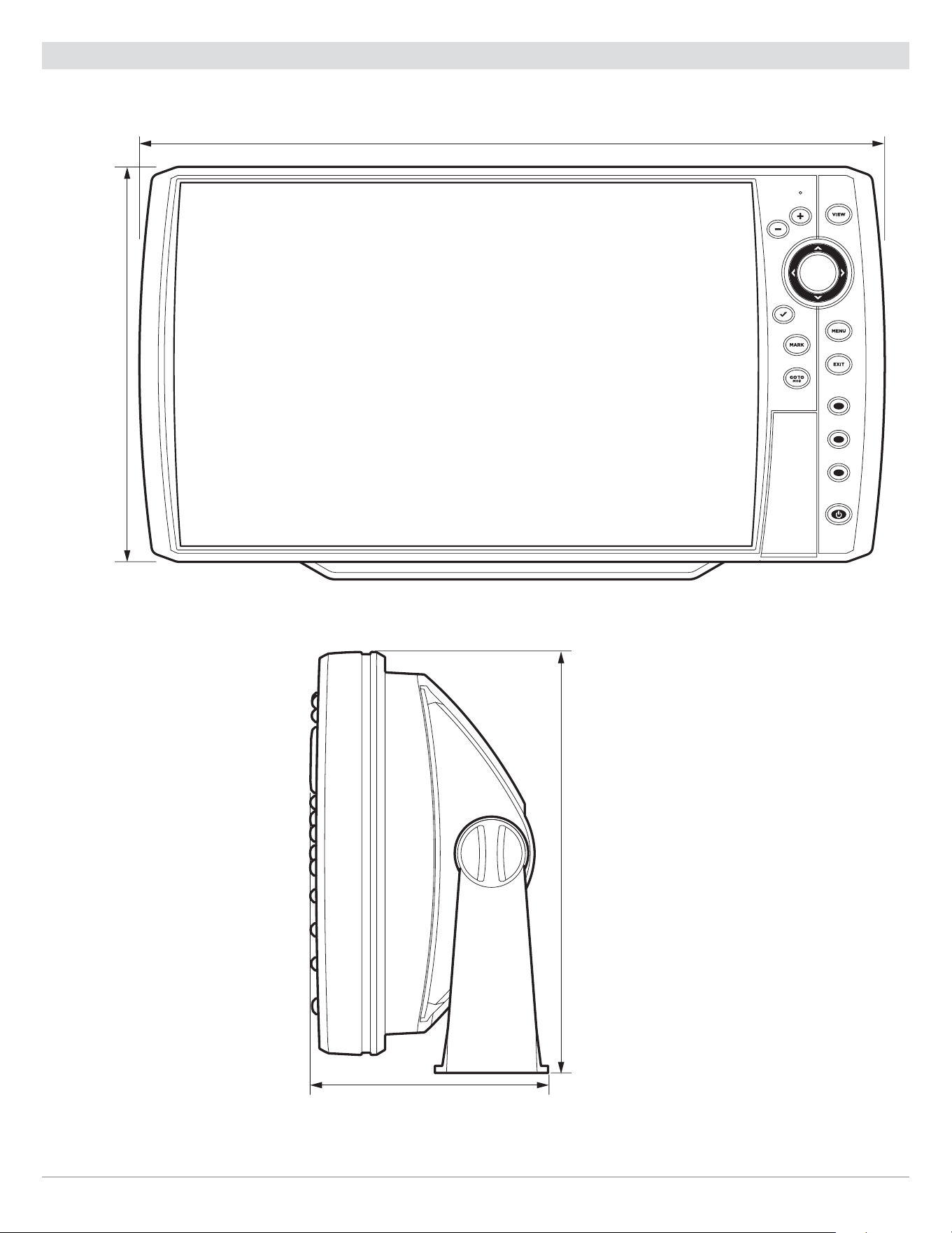
302
Specifications
HELIX 9 G3N Control Head Measurements
HELIX 9 G3N Gimbal Mount
11.998
||
(304.75 mm)
6.623
||
(168.22 mm)
4.103
||
(104.22 mm)
7.251
||
(184.18 mm)
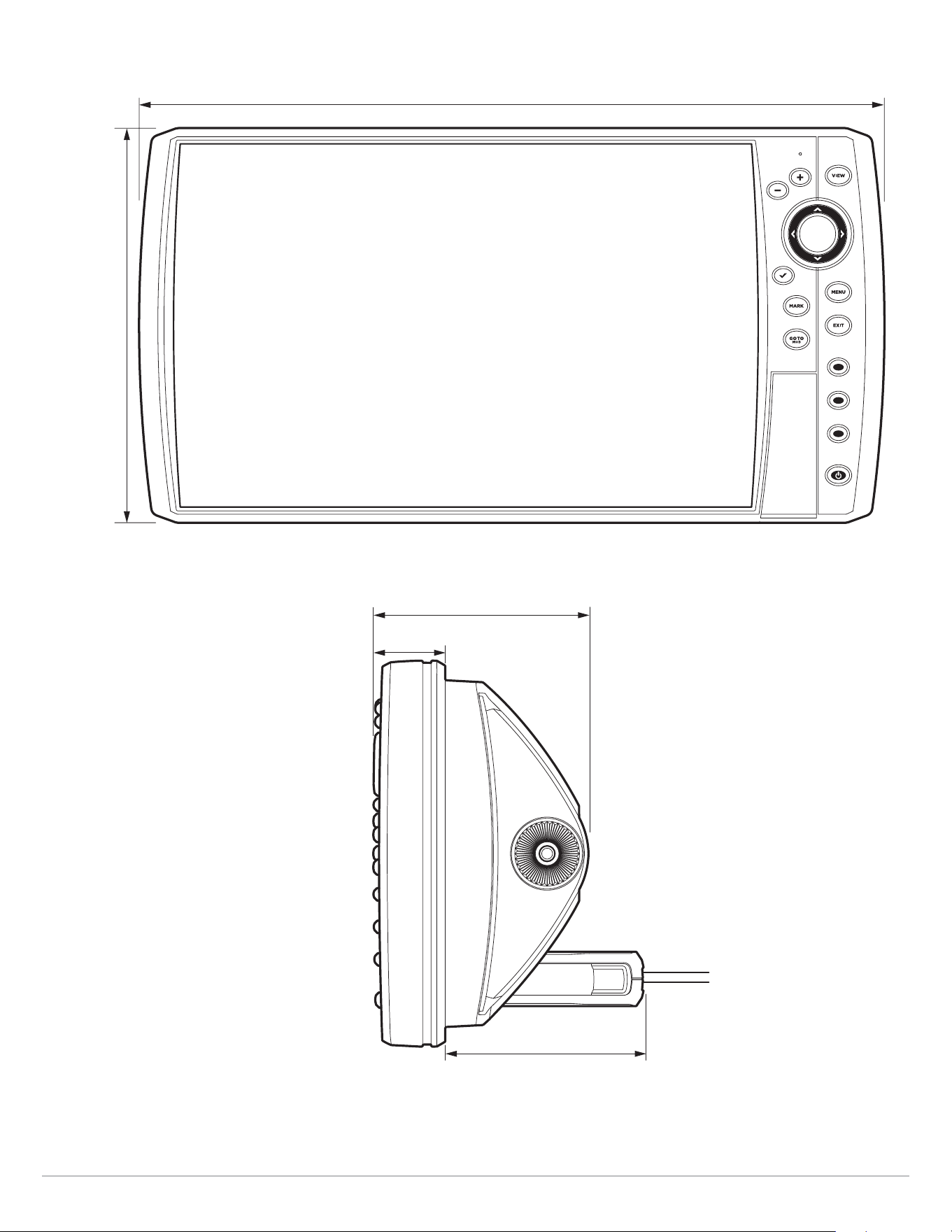
303
Specifications
HELIX 9 G3N In-Dash Mount
11.998
||
(304.75 mm)
6.623
||
(168.22 mm)
3.674
||
(93.32 mm)
3.938
||
(100.03 mm)
1.220
||
(30.99 mm)

304
Specifications
HELIX 9 CHIRP GPS G4N
Control Head
Display Size (diagonal) ................................................................................. 9 inches (228.6 mm)
Pixel Matrix ............................................................................................ WSVGA 600V x 1024H
Display Type ...................................................................................................... TFT Color
Backlight .............................................................................................................. LED
Communication .......................................................... Bluetooth, NMEA 0183, NMEA 2000, Ethernet, Wireless
Power Input ................................................................................................... 10 to 20 VDC
Current Draw ......................................................................................................... 1.9 A
IPX Rating ................................................................. IPX7 Waterproof/Submersible @ 1 m for 30 minutes
Bluetooth Frequency Range ................................................................................ 2402 to 2480 MHz
Bluetooth Output Power ...................................................................................... 10 dBm Typical
Dual Spectrum 2D CHIRP Transducer
XNT 9 HW T (includes built-in temperature probe)
Default Operating Frequency ............................................................................... 150 kHz - 220 kHz
Depth Capability ............................................................................................ 1200 ft (366 m)
Area of Coverage ............................................................................ Full: 42°@-10 dB in 150-220 kHz
Wide: 42°@-10 dB in 140-200 kHz
Narrow: 25°@-10 dB in 180-240 kHz
Power Output (MAX) .............................................................. 500 Watts (RMS), 4000 Watts (Peak to Peak)
NOTE: Humminbird verifies maximum stated depth in saltwater conditions, but actual depth performance may vary due to
transducer installation, water type, thermal layers, bottom composition, and slope.
NOTE: Product specifications and features are subject to change without notice.

305
Specifications
HELIX 9 CHIRP MEGA DI+ GPS G4N
Control Head
Display Size (diagonal) ................................................................................. 9 inches (228.6 mm)
Pixel Matrix ............................................................................................ WSVGA 600V x 1024H
Display Type ...................................................................................................... TFT Color
Backlight .............................................................................................................. LED
Communication .......................................................... Bluetooth, NMEA 0183, NMEA 2000, Ethernet, Wireless
Power Input ................................................................................................... 10 to 20 VDC
Current Draw ......................................................................................................... 1.9 A
IPX Rating ................................................................. IPX7 Waterproof/Submersible @ 1 m for 30 minutes
Bluetooth Frequency Range ................................................................................ 2402 to 2480 MHz
Bluetooth Output Power ...................................................................................... 10 dBm Typical
CHIRP MEGA Down Imaging+ Transducer
XM 9 HW MDI T (includes built-in temperature probe)
Down Imaging
Operating Frequency ................................................................................. 455 kHz, 800 kHz, MEGA
Depth Capability ..................................................................................... 455 kHz: 400 ft (122 m)
800 kHz: 125 ft (38m)
MEGA: 200 ft (61 m)
Area of Coverage ............................................................................455 kHz: 75° @ -10 dB in 455 kHz
800 kHz: 45° @ -10 dB in 800 kHz
MEGA: 75° @ -10 dB in MEGA kHz
Power Output (MAX) .............................................................. 500 Watts (RMS), 4000 Watts (Peak to Peak)
Dual Spectrum
Default Operating Frequency ............................................................................... 150 kHz - 220 kHz
Depth Capability ............................................................................................ 1200 ft (366 m)
Area of Coverage ............................................................................ Full: 42°@-10 dB in 150-220 kHz
Wide: 42°@-10 dB in 140-200 kHz
Narrow: 25°@-10 dB in 180-240 kHz
Power Output (MAX) .............................................................. 500 Watts (RMS), 4000 Watts (Peak to Peak)
NOTE: Humminbird verifies maximum stated depth in saltwater conditions, but actual depth performance may vary due to
transducer installation, water type, thermal layers, bottom composition, and slope.
NOTE: Product specifications and features are subject to change without notice.

306
Specifications
HELIX 9 CHIRP MEGA SI+GPS G4N
Control Head
Display Size (diagonal) ................................................................................. 9 inches (228.6 mm)
Pixel Matrix ............................................................................................ WSVGA 600V x 1024H
Display Type ...................................................................................................... TFT Color
Backlight .............................................................................................................. LED
Communication .......................................................... Bluetooth, NMEA 0183, NMEA 2000, Ethernet, Wireless
Power Input ................................................................................................... 10 to 20 VDC
Current Draw ..........................................................................................................1.9 A
IPX Rating ................................................................. IPX7 Waterproof/Submersible @ 1 m for 30 minutes
Bluetooth Frequency Range ................................................................................ 2402 to 2480 MHz
Bluetooth Output Power ...................................................................................... 10 dBm Typical
CHIRP MEGA Side Imaging+ Transducer
XM 9 HW MSI T (includes built-in temperature probe)
Side Imaging
Operating Frequency ................................................................................. 455 kHz, 800 kHz, MEGA
Depth Capability ..................................................................................... 455 kHz: 800 ft (244 m)
800 kHz: 250 ft (76 m)
MEGA: 400 ft (122 m)
Area of Coverage ........................................................................... 455 kHz: 86° @ -10 dB in 455 kHz
800 kHz: 86° @ -10 dB in 800 kHz
MEGA: 86° @ -10 dB in MEGA kHz
Power Output (MAX) .............................................................. 500 Watts (RMS), 4000 Watts (Peak to Peak)
Down Imaging
Operating Frequency ................................................................................. 455 kHz, 800 kHz, MEGA
Depth Capability ..................................................................................... 455 kHz: 400 ft (122 m)
800 kHz: 125 ft (38 m)
MEGA: 200 ft (61 m)
Area of Coverage ........................................................................... 455 kHz: 75° @ -10 dB in 455 kHz
800 kHz: 45° @ -10 dB in 800 kHz
MEGA: 75° @ -10 dB in MEGA kHz
Power Output (MAX) .............................................................. 500 Watts (RMS), 4000 Watts (Peak to Peak)

307
Specifications
Dual Spectrum
Default Operating Frequency ............................................................................... 150 kHz - 220 kHz
Depth Capability ............................................................................................ 1200 ft (366 m)
Area of Coverage ............................................................................ Full: 42°@-10 dB in 150-220 kHz
Wide: 42°@-10 dB in 140-200 kHz
Narrow: 25°@-10 dB in 180-240 kHz
Power Output (MAX) .............................................................. 500 Watts (RMS), 4000 Watts (Peak to Peak)
NOTE: Humminbird verifies maximum stated depth in saltwater conditions, but actual depth performance may vary due to
transducer installation, water type, thermal layers, bottom composition, and slope.
NOTE: Product specifications and features are subject to change without notice.

308
Specifications
ICE HELIX 9 CHIRP MEGA SI+GPS G4N
Control Head
Display Size (diagonal) ................................................................................. 9 inches (228.6 mm)
Pixel Matrix ............................................................................................ WSVGA 600V x 1024H
Display Type ...................................................................................................... TFT Color
Backlight .............................................................................................................. LED
Communication .......................................................... Bluetooth, NMEA 0183, NMEA 2000, Ethernet, Wireless
Power Input ................................................................................................... 10 to 20 VDC
Current Draw ..........................................................................................................1.9 A
IPX Rating ................................................................. IPX7 Waterproof/Submersible @ 1 m for 30 minutes
Bluetooth Frequency Range ................................................................................ 2402 to 2480 MHz
Bluetooth Output Power ...................................................................................... 10 dBm Typical
Dual Spectrum ICE Transducer
XI 9 1521
Default Operating Frequency ............................................................................... 150 kHz - 220 kHz
Depth Capability ............................................................................................. 400 ft (122 m)
Area of Coverage ............................................................................. 15°-21°@-3 dB in 130-250 kHz
Power Output (MAX) .............................................................. 500 Watts (RMS), 4000 Watts (Peak to Peak)
NOTE: Humminbird verifies maximum stated depth in saltwater conditions, but actual depth performance may vary due to
transducer installation, water type, thermal layers, bottom composition, and slope.
NOTE: Product specifications and features are subject to change without notice.
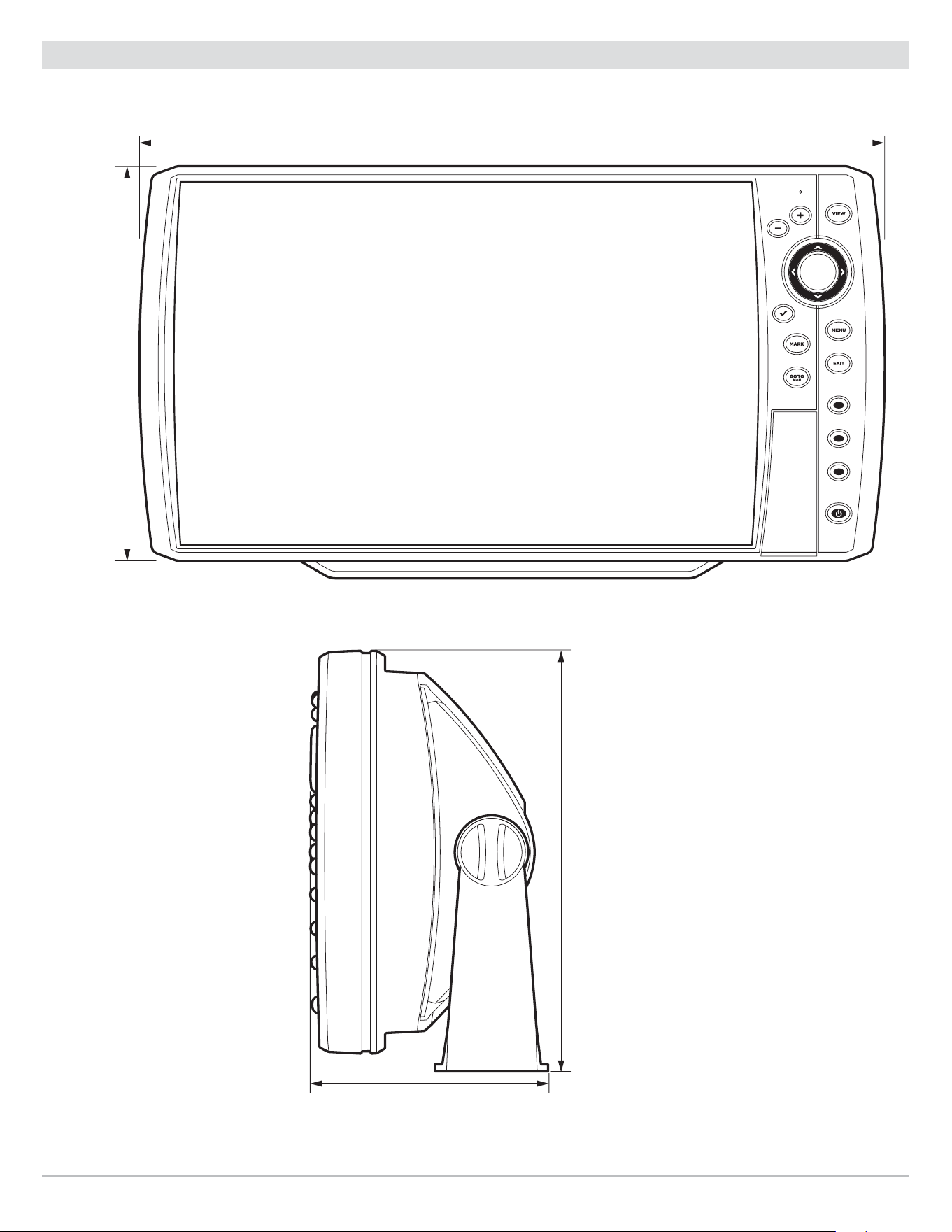
309
Specifications
HELIX 9 G4N Control Head Measurements
HELIX 9 G4N Gimbal Mount
11.998
||
(304.75 mm)
6.623
||
(168.22 mm)
4.103
||
(104.22 mm)
7.251
||
(184.18 mm)
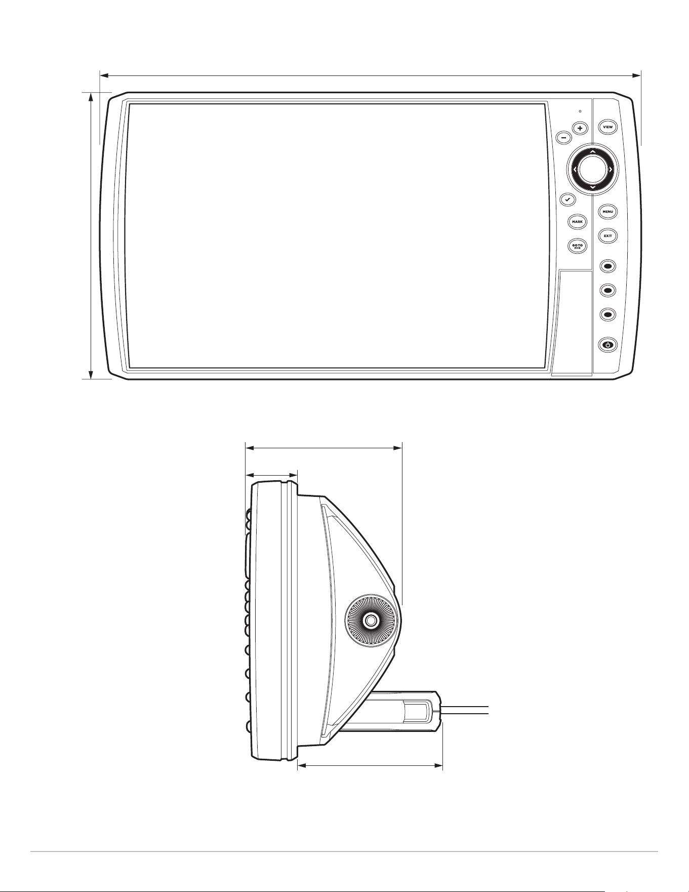
310
Specifications
HELIX 9 G4N In-Dash Mount
11.998
||
(304.75 mm)
6.623
||
(168.22 mm)
3.674
||
(93.32 mm)
3.938
||
(100.03 mm)
1.220
||
(30.99 mm)

311
Specifications
HELIX 10 CHIRP GPS G2N
Control Head
Display Size (diagonal) ............................................................................... 10.1 inches (256.5 mm)
Pixel Matrix ............................................................................................ WSVGA 600V x 1024H
Display Type ...................................................................................................... TFT Color
Backlight .............................................................................................................. LED
Communication ........................................................................................ NMEA 0183, Ethernet
Power Input ................................................................................................... 10 to 20 VDC
Current Draw ......................................................................................................... 1.5 A
IPX Rating ................................................................. IPX7 Waterproof/Submersible @ 1 m for 30 minutes
Bluetooth Frequency Range ................................................................................ 2402 to 2480 MHz
Bluetooth Output Power ...................................................................................... 10 dBm Typical
CHIRP DualBeam PLUS Transducer
XNT 9 20 T (includes built-in temperature probe)
Operating Frequency ........................................................................................ 200 kHz, 83 kHz
Depth Capability ............................................................................................ 1500 ft (457 m)
Area of Coverage ............................................................... 60°@-10 dB in 83 kHz, 20°@-10 dB in 200 kHz
Power Output (MAX) .............................................................. 500 Watts (RMS), 4000 Watts (Peak to Peak)
NOTE: Humminbird verifies maximum stated depth in saltwater conditions, but actual depth performance may vary due to
transducer installation, water type, thermal layers, bottom composition, and slope.
NOTE: Product specifications and features are subject to change without notice.

312
Specifications
HELIX 10 CHIRP DI GPS G2N
Control Head
Display Size (diagonal) ...............................................................................
10.1 inches (256.5 mm)
Pixel Matrix ............................................................................................ WSVGA 600V x 1024H
Display Type ...................................................................................................... TFT Color
Backlight .............................................................................................................. LED
Communication ........................................................................................ NMEA 0183, Ethernet
Power Input ................................................................................................... 10 to 20 VDC
Current Draw ......................................................................................................... 2.7 A
IPX Rating ................................................................. IPX7 Waterproof/Submersible @ 1 m for 30 minutes
Bluetooth Frequency Range ................................................................................ 2402 to 2480 MHz
Bluetooth Output Power ...................................................................................... 10 dBm Typical
CHIRP Down Imaging Transducer
XNT 9 DI T (includes built-in temperature probe)
Down Imaging
Operating Frequency ....................................................................................... 455 kHz, 800 kHz
Depth Capability ............................................................................................. 350 ft (107 m)
Area of Coverage .............................................................75º @ -10 dB in 455 kHz, 45º @ -10 dB in 800 kHz
Power Output (MAX) .............................................................. 500 Watts (RMS), 4000 Watts (Peak to Peak)
DualBeam PLUS
Operating Frequency ....................................................................................... 200 kHz, 455 kHz
Depth Capability ............................................................................................. 600 ft (183 m)
Area of Coverage .............................................................28° @ -10 dB in 200 kHz, 16° @ -10 dB in 455 kHz
Power Output (MAX) .............................................................. 500 Watts (RMS), 4000 Watts (Peak to Peak)
NOTE: Humminbird verifies maximum stated depth in saltwater conditions, but actual depth performance may vary due to
transducer installation, water type, thermal layers, bottom composition, and slope.
NOTE: Product specifications and features are subject to change without notice.

313
Specifications
HELIX 10 CHIRP DI GPS G2N (CHIRP MEGA DI)
Control Head
Display Size (diagonal) ............................................................................... 10.1 inches (256.5 mm)
Pixel Matrix ............................................................................................ WSVGA 600V x 1024H
Display Type ...................................................................................................... TFT Color
Backlight .............................................................................................................. LED
Communication ........................................................................................ NMEA 0183, Ethernet
Power Input ................................................................................................... 10 to 20 VDC
Current Draw ......................................................................................................... 2.7 A
IPX Rating ................................................................. IPX7 Waterproof/Submersible @ 1 m for 30 minutes
Bluetooth Frequency Range ................................................................................ 2402 to 2480 MHz
Bluetooth Output Power ...................................................................................... 10 dBm Typical
CHIRP MEGA Down Imaging Transducer
XM 9 MDI T (includes built-in temperature probe)
Down Imaging
Operating Frequency ................................................................................. 455 kHz, 800 kHz, MEGA
Depth Capability ..................................................................................... 455 kHz: 400 ft (122 m)
800 kHz: 125 ft (38 m)
MEGA: 125 ft (38 m)
Area of Coverage .................................................................................... 75° @ -10 dB in 455 kHz
45° @ -10 dB in 800 kHz
MEGA: 75° @ -10 dB in MEGA kHz
Power Output (MAX) .............................................................. 500 Watts (RMS), 4000 Watts (Peak to Peak)
Dual Spectrum
Default Operating Frequency ............................................................................... 150 kHz - 220 kHz
Depth Capability ............................................................................................ 1000 ft (305 m)
Area of Coverage ............................................................................ Full: 42°@-10 dB in 150-220 kHz
Wide: 42°@-10 dB in 140-200 kHz
Narrow: 25°@-10 dB in 180-240 kHz
Power Output (MAX) .............................................................. 500 Watts (RMS), 4000 Watts (Peak to Peak)
NOTE: Humminbird verifies maximum stated depth in saltwater conditions, but actual depth performance may vary due to
transducer installation, water type, thermal layers, bottom composition, and slope.
NOTE: Product specifications and features are subject to change without notice.

314
Specifications
HELIX 10 CHIRP SI GPS G2N (CHIRP MEGA SI)
Control Head
Display Size (diagonal) ............................................................................... 10.1 inches (256.5 mm)
Pixel Matrix ............................................................................................ WSVGA 600V x 1024H
Display Type ...................................................................................................... TFT Color
Backlight .............................................................................................................. LED
Communication ........................................................................................ NMEA 0183, Ethernet
Power Input ................................................................................................... 10 to 20 VDC
Current Draw ......................................................................................................... 2.7 A
IPX Rating ................................................................. IPX7 Waterproof/Submersible @ 1 m for 30 minutes
Bluetooth Frequency Range ................................................................................ 2402 to 2480 MHz
Bluetooth Output Power ...................................................................................... 10 dBm Typical
CHIRP MEGA Side Imaging Transducer
XM 9 20 MSI T (includes built-in temperature probe)
Side Imaging
Operating Frequency ................................................................................. 455 kHz, 800 kHz, MEGA
Range Capability ......................................................................... 455 kHz: 800 ft (244 m) Side to Side
800 kHz: 250 ft (76 m) Side to Side
MEGA: 250 ft (76 m) Side to Side
Area of Coverage ............................................................ (2) 86º @ -10 dB in 455 kHz (180º Total Coverage)
(2) 55º @ -10 dB in 800 kHz (130º Total Coverage)
MEGA: (2) 86º @ -10 dB in MEGA kHz (180º Total Coverage)
Power Output (MAX) .............................................................. 500 Watts (RMS), 4000 Watts (Peak to Peak)
Down Imaging
Operating Frequency ................................................................................. 455 kHz, 800 kHz, MEGA
Depth Capability ..................................................................................... 455 kHz: 400 ft (122 m)
800 kHz: 125 ft (38 m)
MEGA: 125 ft (38 m)
Area of Coverage .................................................................................... 75° @ -10 dB in 455 kHz
45° @ -10 dB in 800 kHz
MEGA: 75° @ -10 dB in MEGA kHz
Power Output (MAX) .............................................................. 500 Watts (RMS), 4000 Watts (Peak to Peak)

315
Specifications
DualBeam PLUS
Operating Frequency ........................................................................................ 200 kHz, 83 kHz
Depth Capability ............................................................................................ 1500 ft (457 m)
Area of Coverage ..................................................................................... 60° @ -10 dB in 83 kHz,
20° @ -10 dB in 200 kHz
Power Output (MAX) .............................................................. 500 Watts (RMS), 4000 Watts (Peak to Peak)
NOTE: Humminbird verifies maximum stated depth in saltwater conditions, but actual depth performance may vary due to
transducer installation, water type, thermal layers, bottom composition, and slope.
NOTE: Product specifications and features are subject to change without notice.

316
Specifications
HELIX 10 CHIRP GPS G3N
Control Head
Display Size (diagonal) ...............................................................................
10.1 inches (256.5 mm)
Pixel Matrix ............................................................................................ WSVGA 600V x 1024H
Display Type ...................................................................................................... TFT Color
Backlight .............................................................................................................. LED
Communication ........................................................................................ NMEA 0183, Ethernet
Power Input ................................................................................................... 10 to 20 VDC
Current Draw ......................................................................................................... 2.4 A
IPX Rating ................................................................. IPX7 Waterproof/Submersible @ 1 m for 30 minutes
Bluetooth Frequency Range ................................................................................ 2402 to 2480 MHz
Bluetooth Output Power ...................................................................................... 10 dBm Typical
Dual Spectrum 2D CHIRP Transducer
XNT 9 HW T (includes built-in temperature probe)
Default Operating Frequency ............................................................................... 150 kHz - 220 kHz
Depth Capability ............................................................................................ 1000 ft (305 m)
Area of Coverage ............................................................................ Full: 42°@-10 dB in 150-220 kHz
Wide: 42°@-10 dB in 140-200 kHz
Narrow: 25°@-10 dB in 180-240 kHz
Power Output (MAX) .............................................................. 500 Watts (RMS), 4000 Watts (Peak to Peak)
NOTE: Humminbird verifies maximum stated depth in saltwater conditions, but actual depth performance may vary due to
transducer installation, water type, thermal layers, bottom composition, and slope.
NOTE: Product specifications and features are subject to change without notice.

317
Specifications
HELIX 10 CHIRP MEGA DI+ GPS G3N
Control Head
Display Size (diagonal) ............................................................................... 10.1 inches (256.5 mm)
Pixel Matrix ............................................................................................ WSVGA 600V x 1024H
Display Type ...................................................................................................... TFT Color
Backlight .............................................................................................................. LED
Communication ........................................................................................ NMEA 0183, Ethernet
Power Input ................................................................................................... 10 to 20 VDC
Current Draw ......................................................................................................... 2.4 A
IPX Rating ................................................................. IPX7 Waterproof/Submersible @ 1 m for 30 minutes
Bluetooth Frequency Range ................................................................................ 2402 to 2480 MHz
Bluetooth Output Power ...................................................................................... 10 dBm Typical
CHIRP MEGA Down Imaging+ Transducer
XM 9 HW MDI T (includes built-in temperature probe)
Down Imaging
Operating Frequency ................................................................................. 455 kHz, 800 kHz, MEGA
Depth Capability ..................................................................................... 455 kHz: 400 ft (122 m)
800 kHz: 125 ft (38m)
MEGA: 200 ft (61 m)
Area of Coverage ............................................................................455 kHz: 75° @ -10 dB in 455 kHz
800 kHz: 45° @ -10 dB in 800 kHz
MEGA: 75° @ -10 dB in MEGA kHz
Power Output (MAX) .............................................................. 500 Watts (RMS), 4000 Watts (Peak to Peak)
Dual Spectrum
Default Operating Frequency ............................................................................... 150 kHz - 220 kHz
Depth Capability ............................................................................................ 1000 ft (305 m)
Area of Coverage ............................................................................ Full: 42°@-10 dB in 150-220 kHz
Wide: 42°@-10 dB in 140-200 kHz
Narrow: 25°@-10 dB in 180-240 kHz
Power Output (MAX) .............................................................. 500 Watts (RMS), 4000 Watts (Peak to Peak)
NOTE: Humminbird verifies maximum stated depth in saltwater conditions, but actual depth performance may vary due to
transducer installation, water type, thermal layers, bottom composition, and slope.
NOTE: Product specifications and features are subject to change without notice.

318
Specifications
HELIX 10 CHIRP MEGA SI+ GPS G3N
Control Head
Display Size (diagonal) ...............................................................................
10.1 inches (256.5 mm)
Pixel Matrix ............................................................................................ WSVGA 600V x 1024H
Display Type ...................................................................................................... TFT Color
Backlight .............................................................................................................. LED
Communication ........................................................................................ NMEA 0183, Ethernet
Power Input ................................................................................................... 10 to 20 VDC
Current Draw ......................................................................................................... 2.4 A
IPX Rating ................................................................. IPX7 Waterproof/Submersible @ 1 m for 30 minutes
Bluetooth Frequency Range ................................................................................ 2402 to 2480 MHz
Bluetooth Output Power ...................................................................................... 10 dBm Typical
CHIRP MEGA Side Imaging+ Transducer
XM 9 HW MSI T (includes built-in temperature probe)
Side Imaging
Operating Frequency ................................................................................. 455 kHz, 800 kHz, MEGA
Depth Capability ..................................................................................... 455 kHz: 800 ft (244 m)
800 kHz: 250 ft (76 m)
MEGA: 400 ft (122 m)
Area of Coverage ........................................................................... 455 kHz: 86° @ -10 dB in 455 kHz
800 kHz: 86° @ -10 dB in 800 kHz
MEGA: 86° @ -10 dB in MEGA kHz
Power Output (MAX) .............................................................. 500 Watts (RMS), 4000 Watts (Peak to Peak)
Down Imaging
Operating Frequency ................................................................................. 455 kHz, 800 kHz, MEGA
Depth Capability ..................................................................................... 455 kHz: 400 ft (122 m)
800 kHz: 125 ft (38 m)
MEGA: 200 ft (61 m)
Area of Coverage ........................................................................... 455 kHz: 75° @ -10 dB in 455 kHz
800 kHz: 45° @ -10 dB in 800 kHz
MEGA: 75° @ -10 dB in MEGA kHz
Power Output (MAX) .............................................................. 500 Watts (RMS), 4000 Watts (Peak to Peak)

319
Specifications
Dual Spectrum
Default Operating Frequency ............................................................................... 150 kHz - 220 kHz
Depth Capability ............................................................................................ 1000 ft (305 m)
Area of Coverage ............................................................................ Full: 42°@-10 dB in 150-220 kHz
Wide: 42°@-10 dB in 140-200 kHz
Narrow: 25°@-10 dB in 180-240 kHz
Power Output (MAX) .............................................................. 500 Watts (RMS), 4000 Watts (Peak to Peak)
NOTE: Humminbird verifies maximum stated depth in saltwater conditions, but actual depth performance may vary due to
transducer installation, water type, thermal layers, bottom composition, and slope.
NOTE: Product specifications and features are subject to change without notice.

320
Specifications
HELIX 10 CHIRP GPS G4N
Control Head
Display Size (diagonal) ...............................................................................
10.1 inches (256.5 mm)
Pixel Matrix ............................................................................................ WSVGA 600V x 1024H
Display Type ...................................................................................................... TFT Color
Backlight .............................................................................................................. LED
Communication .......................................................... Bluetooth, NMEA 0183, NMEA 2000, Ethernet, Wireless
Power Input ................................................................................................... 10 to 20 VDC
Current Draw ......................................................................................................... 2.7 A
IPX Rating ................................................................. IPX7 Waterproof/Submersible @ 1 m for 30 minutes
Bluetooth Frequency Range ................................................................................ 2402 to 2480 MHz
Bluetooth Output Power ...................................................................................... 10 dBm Typical
Dual Spectrum 2D CHIRP Transducer
XNT 9 HW T (includes built-in temperature probe)
Default Operating Frequency ............................................................................... 150 kHz - 220 kHz
Depth Capability ............................................................................................ 1200 ft (366 m)
Area of Coverage ............................................................................ Full: 42°@-10 dB in 150-220 kHz
Wide: 42°@-10 dB in 140-200 kHz
Narrow: 25°@-10 dB in 180-240 kHz
Power Output (MAX) .............................................................. 500 Watts (RMS), 4000 Watts (Peak to Peak)
NOTE: Humminbird verifies maximum stated depth in saltwater conditions, but actual depth performance may vary due to
transducer installation, water type, thermal layers, bottom composition, and slope.
NOTE: Product specifications and features are subject to change without notice.

321
Specifications
HELIX 10 CHIRP MEGA DI+ GPS G4N
Control Head
Display Size (diagonal) ............................................................................... 10.1 inches (256.5 mm)
Pixel Matrix ............................................................................................ WSVGA 600V x 1024H
Display Type ...................................................................................................... TFT Color
Backlight .............................................................................................................. LED
Communication ..........................................................Bluetooth, NMEA 0183, NMEA 2000, Ethernet, Wireless
Power Input ................................................................................................... 10 to 20 VDC
Current Draw ......................................................................................................... 2.7 A
IPX Rating ................................................................. IPX7 Waterproof/Submersible @ 1 m for 30 minutes
Bluetooth Frequency Range ................................................................................ 2402 to 2480 MHz
Bluetooth Output Power ...................................................................................... 10 dBm Typical
CHIRP MEGA Down Imaging+ Transducer
XM 9 HW MDI T (includes built-in temperature probe)
Down Imaging
Operating Frequency ................................................................................. 455 kHz, 800 kHz, MEGA
Depth Capability ..................................................................................... 455 kHz: 400 ft (122 m)
800 kHz: 125 ft (38m)
MEGA: 200 ft (61 m)
Area of Coverage ............................................................................455 kHz: 75° @ -10 dB in 455 kHz
800 kHz: 45° @ -10 dB in 800 kHz
MEGA: 75° @ -10 dB in MEGA kHz
Power Output (MAX) .............................................................. 500 Watts (RMS), 4000 Watts (Peak to Peak)
Dual Spectrum
Default Operating Frequency ............................................................................... 150 kHz - 220 kHz
Depth Capability ............................................................................................ 1200 ft (366 m)
Area of Coverage ............................................................................ Full: 42°@-10 dB in 150-220 kHz
Wide: 42°@-10 dB in 140-200 kHz
Narrow: 25°@-10 dB in 180-240 kHz
Power Output (MAX) .............................................................. 500 Watts (RMS), 4000 Watts (Peak to Peak)
NOTE: Humminbird verifies maximum stated depth in saltwater conditions, but actual depth performance may vary due to
transducer installation, water type, thermal layers, bottom composition, and slope.
NOTE: Product specifications and features are subject to change without notice.

322
Specifications
HELIX 10 CHIRP MEGA SI+ GPS G4N
Control Head
Display Size (diagonal) ...............................................................................
10.1 inches (256.5 mm)
Pixel Matrix ............................................................................................ WSVGA 600V x 1024H
Display Type ...................................................................................................... TFT Color
Backlight .............................................................................................................. LED
Communication .......................................................... Bluetooth, NMEA 0183, NMEA 2000, Ethernet, Wireless
Power Input ................................................................................................... 10 to 20 VDC
Current Draw ......................................................................................................... 2.7 A
IPX Rating ................................................................. IPX7 Waterproof/Submersible @ 1 m for 30 minutes
Bluetooth Frequency Range ................................................................................ 2402 to 2480 MHz
Bluetooth Output Power ...................................................................................... 10 dBm Typical
CHIRP MEGA Side Imaging+ Transducer
XM 9 HW MSI T (includes built-in temperature probe)
Side Imaging
Operating Frequency ................................................................................. 455 kHz, 800 kHz, MEGA
Depth Capability ..................................................................................... 455 kHz: 800 ft (244 m)
800 kHz: 250 ft (76 m)
MEGA: 400 ft (122 m)
Area of Coverage ........................................................................... 455 kHz: 86° @ -10 dB in 455 kHz
800 kHz: 86° @ -10 dB in 800 kHz
MEGA: 86° @ -10 dB in MEGA kHz
Power Output (MAX) .............................................................. 500 Watts (RMS), 4000 Watts (Peak to Peak)
Down Imaging
Operating Frequency ................................................................................. 455 kHz, 800 kHz, MEGA
Depth Capability ..................................................................................... 455 kHz: 400 ft (122 m)
800 kHz: 125 ft (38 m)
MEGA: 200 ft (61 m)
Area of Coverage ........................................................................... 455 kHz: 75° @ -10 dB in 455 kHz
800 kHz: 45° @ -10 dB in 800 kHz
MEGA: 75° @ -10 dB in MEGA kHz
Power Output (MAX) .............................................................. 500 Watts (RMS), 4000 Watts (Peak to Peak)

323
Specifications
Dual Spectrum
Default Operating Frequency ............................................................................... 150 kHz - 220 kHz
Depth Capability ............................................................................................ 1200 ft (366 m)
Area of Coverage ............................................................................ Full: 42°@-10 dB in 150-220 kHz
Wide: 42°@-10 dB in 140-200 kHz
Narrow: 25°@-10 dB in 180-240 kHz
Power Output (MAX) .............................................................. 500 Watts (RMS), 4000 Watts (Peak to Peak)
NOTE: Humminbird verifies maximum stated depth in saltwater conditions, but actual depth performance may vary due to
transducer installation, water type, thermal layers, bottom composition, and slope.
NOTE: Product specifications and features are subject to change without notice.
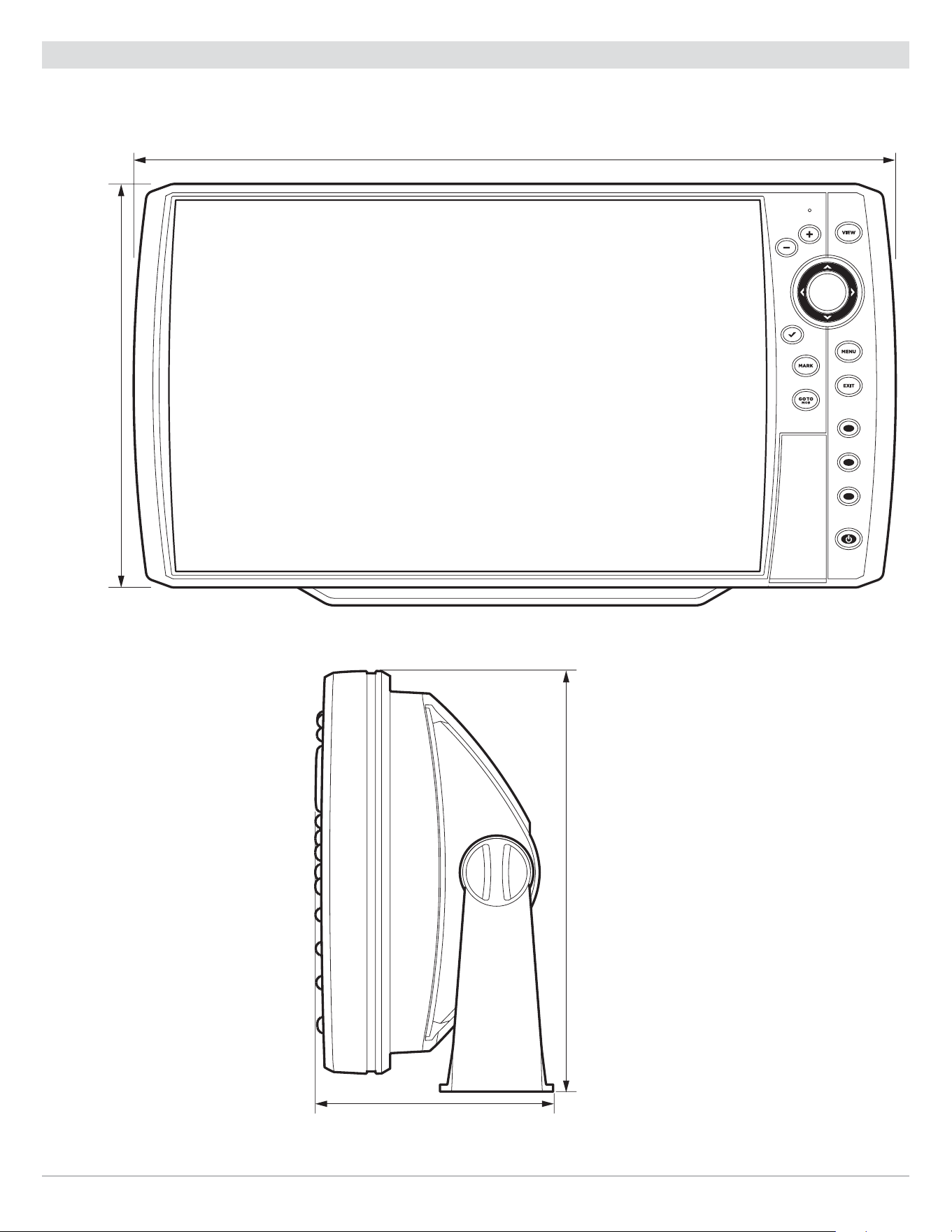
324
Specifications
HELIX 10 Control Head Measurements
HELIX 10 Gimbal Mount
13.44
||
(341.38 mm)
7.114
||
(180.7 mm)
4.203
||
(106.76 mm)
7.5
||
(191 mm)

325
Specifications
HELIX 10 In-Dash Mount
13.44
||
(341.38 mm)
7.114
||
(180.7 mm)
3.685
||
(93.59 mm)
3.991
||
(101.37 mm)
1.324
||
(33.63 mm)

326
Specifications
HELIX 12 CHIRP GPS G2N
Control Head
Display Size (diagonal) ...............................................................................
12.1 inches (307.3 mm)
Pixel Matrix ............................................................................................. WXGA 800V x 1280H
Display Type ...................................................................................................... TFT Color
Backlight .............................................................................................................. LED
Communication ........................................................................................ NMEA 0183, Ethernet
Power Input ................................................................................................... 10 to 20 VDC
Current Draw ......................................................................................................... 2.2 A
IPX Rating ................................................................. IPX7 Waterproof/Submersible @ 1 m for 30 minutes
Bluetooth Frequency Range ................................................................................ 2402 to 2480 MHz
Bluetooth Output Power ...................................................................................... 10 dBm Typical
CHIRP DualBeam PLUS Transducer
XNT 9 20 T (includes built-in temperature probe)
Operating Frequency ........................................................................................ 83 kHz, 200 kHz
Depth Capability ............................................................................................ 1500 ft (457 m)
Area of Coverage ............................................................... 60°@-10 dB in 83 kHz, 20°@-10 dB in 200 kHz
Power Output (MAX) .............................................................. 500 Watts (RMS), 4000 Watts (Peak to Peak)
NOTE: Humminbird verifies maximum stated depth in saltwater conditions, but actual depth performance may vary due to
transducer installation, water type, thermal layers, bottom composition, and slope.
NOTE: Product specifications and features are subject to change without notice.

327
Specifications
HELIX 12 CHIRP DI GPS G2N
Control Head
Display Size (diagonal) ...............................................................................
12.1 inches (307.3 mm)
Pixel Matrix ............................................................................................. WXGA 800V x 1280H
Display Type ...................................................................................................... TFT Color
Backlight .............................................................................................................. LED
Communication ........................................................................................ NMEA 0183, Ethernet
Power Input ................................................................................................... 10 to 20 VDC
Current Draw ......................................................................................................... 3.0 A
IPX Rating ................................................................. IPX7 Waterproof/Submersible @ 1 m for 30 minutes
Bluetooth Frequency Range ................................................................................ 2402 to 2480 MHz
Bluetooth Output Power ...................................................................................... 10 dBm Typical
CHIRP Down Imaging Transducer
XNT 9 DI T (includes built-in temperature probe)
Down Imaging
Operating Frequency ....................................................................................... 455 kHz, 800 kHz
Depth Capability ............................................................................................. 350 ft (107 m)
Area of Coverage ............................................................ 75º @ -10 dB in 455 kHz, 45º @ -10 dB in 800 kHz
Power Output (MAX) .............................................................. 500 Watts (RMS), 4000 Watts (Peak to Peak)
DualBeam PLUS
Operating Frequency ....................................................................................... 200 kHz, 455 kHz
Depth Capability ............................................................................................. 600 ft (183 m)
Area of Coverage ............................................................ 28° @ -10 dB in 200 kHz, 16° @ -10 dB in 455 kHz
Power Output (MAX) .............................................................. 500 Watts (RMS), 4000 Watts (Peak to Peak)
NOTE: Humminbird verifies maximum stated depth in saltwater conditions, but actual depth performance may vary due to
transducer installation, water type, thermal layers, bottom composition, and slope.
NOTE: Product specifications and features are subject to change without notice.

328
Specifications
HELIX 12 CHIRP DI GPS G2N (CHIRP MEGA DI)
Control Head
Display Size (diagonal) ...............................................................................
12.1 inches (307.3 mm)
Pixel Matrix ............................................................................................. WXGA 800V x 1280H
Display Type ...................................................................................................... TFT Color
Backlight .............................................................................................................. LED
Communication ........................................................................................ NMEA 0183, Ethernet
Power Input ................................................................................................... 10 to 20 VDC
Current Draw ......................................................................................................... 3.0 A
IPX Rating ................................................................. IPX7 Waterproof/Submersible @ 1 m for 30 minutes
Bluetooth Frequency Range ................................................................................ 2402 to 2480 MHz
Bluetooth Output Power ...................................................................................... 10 dBm Typical
CHIRP MEGA Down Imaging Transducer
XM 9 MDI T (includes built-in temperature probe)
Down Imaging
Operating Frequency ................................................................................. 455 kHz, 800 kHz, MEGA
Depth Capability ..................................................................................... 455 kHz: 400 ft (122 m)
800 kHz: 125 ft (38 m)
MEGA: 125 ft (38 m)
Area of Coverage .................................................................................... 75° @ -10 dB in 455 kHz
45° @ -10 dB in 800 kHz
MEGA: 75° @ -10 dB in MEGA kHz
Power Output (MAX) .............................................................. 500 Watts (RMS), 4000 Watts (Peak to Peak)
Dual Spectrum
Default Operating Frequency ............................................................................... 150 kHz - 220 kHz
Depth Capability ............................................................................................ 1000 ft (305 m)
Area of Coverage ............................................................................ Full: 42°@-10 dB in 150-220 kHz
Wide: 42°@-10 dB in 140-200 kHz
Narrow: 25°@-10 dB in 180-240 kHz
Power Output (MAX) .............................................................. 500 Watts (RMS), 4000 Watts (Peak to Peak)
NOTE: Humminbird verifies maximum stated depth in saltwater conditions, but actual depth performance may vary due to
transducer installation, water type, thermal layers, bottom composition, and slope.
NOTE: Product specifications and features are subject to change without notice.

329
Specifications
HELIX 12 CHIRP SI GPS G2N (CHIRP MEGA SI)
Control Head
Display Size (diagonal) ............................................................................... 12.1 inches (307.3 mm)
Pixel Matrix ............................................................................................. WXGA 800V x 1280H
Display Type ...................................................................................................... TFT Color
Backlight .............................................................................................................. LED
Communication ........................................................................................ NMEA 0183, Ethernet
Power Input ................................................................................................... 10 to 20 VDC
Current Draw ......................................................................................................... 3.0 A
IPX Rating ................................................................. IPX7 Waterproof/Submersible @ 1 m for 30 minutes
Bluetooth Frequency Range ................................................................................ 2402 to 2480 MHz
Bluetooth Output Power ...................................................................................... 10 dBm Typical
CHIRP MEGA Side Imaging Transducer
XM 9 20 MSI T (includes built-in temperature probe)
Side Imaging
Operating Frequency ................................................................................ 455 kHz, 800 kHz, MEGA
Range Capability ......................................................................... 455 kHz: 800 ft (244 m) Side to Side
800 kHz: 250 ft (76 m) Side to Side
MEGA: 250 ft (76 m) Side to Side
Area of Coverage ............................................................ (2) 86º @ -10 dB in 455 kHz (180º Total Coverage)
(2) 55º @ -10 dB in 800 kHz (130º Total Coverage)
MEGA: (2) 86º @ -10 dB in MEGA kHz (180º Total Coverage)
Power Output (MAX) .............................................................. 500 Watts (RMS), 4000 Watts (Peak to Peak)
Down Imaging
Operating Frequency ................................................................................. 455 kHz, 800 kHz, MEGA
Depth Capability ..................................................................................... 455 kHz: 400 ft (122 m)
800 kHz: 125 ft (38 m)
MEGA: 125 ft (38 m)
Area of Coverage .................................................................................... 75° @ -10 dB in 455 kHz
45° @ -10 dB in 800 kHz
MEGA: 75° @ -10 dB in MEGA kHz
Power Output (MAX) .............................................................. 500 Watts (RMS), 4000 Watts (Peak to Peak)

330
Specifications
DualBeam PLUS
Operating Frequency ........................................................................................ 200 kHz, 83 kHz
Depth Capability ............................................................................................ 1500 ft (457 m)
Area of Coverage ..................................................................................... 60° @ -10 dB in 83 kHz,
20° @ -10 dB in 200 kHz
Power Output (MAX) .............................................................. 500 Watts (RMS), 4000 Watts (Peak to Peak)
NOTE: Humminbird verifies maximum stated depth in saltwater conditions, but actual depth performance may vary due to
transducer installation, water type, thermal layers, bottom composition, and slope.
NOTE: Product specifications and features are subject to change without notice.

331
Specifications
HELIX 12 CHIRP GPS G3N
Control Head
Display Size (diagonal) ...............................................................................
12.1 inches (307.3 mm)
Pixel Matrix ............................................................................................. WXGA 800V x 1280H
Display Type ...................................................................................................... TFT Color
Backlight .............................................................................................................. LED
Communication ........................................................................................ NMEA 0183, Ethernet
Power Input ................................................................................................... 10 to 20 VDC
Current Draw ......................................................................................................... 3.3 A
IPX Rating ................................................................. IPX7 Waterproof/Submersible @ 1 m for 30 minutes
Bluetooth Frequency Range ................................................................................ 2402 to 2480 MHz
Bluetooth Output Power ...................................................................................... 10 dBm Typical
Dual Spectrum 2D CHIRP Transducer
XNT 9 HW T (includes built-in temperature probe)
Default Operating Frequency ............................................................................... 150 kHz - 220 kHz
Depth Capability ............................................................................................ 1000 ft (305 m)
Area of Coverage ............................................................................ Full: 42°@-10 dB in 150-220 kHz
Wide: 42°@-10 dB in 140-200 kHz
Narrow: 25°@-10 dB in 180-240 kHz
Power Output (MAX) .............................................................. 500 Watts (RMS), 4000 Watts (Peak to Peak)
NOTE: Humminbird verifies maximum stated depth in saltwater conditions, but actual depth performance may vary due to
transducer installation, water type, thermal layers, bottom composition, and slope.
NOTE: Product specifications and features are subject to change without notice.

332
Specifications
HELIX 12 CHIRP MEGA DI+ GPS G3N
Control Head
Display Size (diagonal) ...............................................................................
12.1 inches (307.3 mm)
Pixel Matrix ............................................................................................. WXGA 800V x 1280H
Display Type ...................................................................................................... TFT Color
Backlight .............................................................................................................. LED
Communication ........................................................................................ NMEA 0183, Ethernet
Power Input ................................................................................................... 10 to 20 VDC
Current Draw ......................................................................................................... 3.3 A
IPX Rating ................................................................. IPX7 Waterproof/Submersible @ 1 m for 30 minutes
Bluetooth Frequency Range ................................................................................ 2402 to 2480 MHz
Bluetooth Output Power ...................................................................................... 10 dBm Typical
CHIRP MEGA Down Imaging+ Transducer
XM 9 HW MDI T (includes built-in temperature probe)
Down Imaging
Operating Frequency ................................................................................. 455 kHz, 800 kHz, MEGA
Depth Capability ..................................................................................... 455 kHz: 400 ft (122 m)
800 kHz: 125 ft (38m)
MEGA: 200 ft (61 m)
Area of Coverage ............................................................................455 kHz: 75° @ -10 dB in 455 kHz
800 kHz: 45° @ -10 dB in 800 kHz
MEGA: 75° @ -10 dB in MEGA kHz
Power Output (MAX) .............................................................. 500 Watts (RMS), 4000 Watts (Peak to Peak)
Dual Spectrum
Default Operating Frequency ............................................................................... 150 kHz - 220 kHz
Depth Capability ............................................................................................ 1000 ft (305 m)
Area of Coverage ............................................................................ Full: 42°@-10 dB in 150-220 kHz
Wide: 42°@-10 dB in 140-200 kHz
Narrow: 25°@-10 dB in 180-240 kHz
Power Output (MAX) .............................................................. 500 Watts (RMS), 4000 Watts (Peak to Peak)
NOTE: Humminbird verifies maximum stated depth in saltwater conditions, but actual depth performance may vary due to
transducer installation, water type, thermal layers, bottom composition, and slope.
NOTE: Product specifications and features are subject to change without notice.

HELIX 12 CHIRP MEGA SI+ GPS G3N
Control Head
Display Size (diagonal) ...............................................................................
12.1 inches (307.3 mm)
Pixel Matrix ............................................................................................. WXGA 800V x 1280H
Display Type ...................................................................................................... TFT Color
Backlight .............................................................................................................. LED
Communication ........................................................................................ NMEA 0183, Ethernet
Power Input ................................................................................................... 10 to 20 VDC
Current Draw ......................................................................................................... 3.3 A
IPX Rating ................................................................. IPX7 Waterproof/Submersible @ 1 m for 30 minutes
Bluetooth Frequency Range ................................................................................ 2402 to 2480 MHz
Bluetooth Output Power ...................................................................................... 10 dBm Typical
CHIRP MEGA Side Imaging+ Transducer
XM 9 HW MSI T (includes built-in temperature probe)
Side Imaging
Operating Frequency ................................................................................. 455 kHz, 800 kHz, MEGA
Depth Capability ..................................................................................... 455 kHz: 800 ft (244 m)
800 kHz: 250 ft (76 m)
MEGA: 400 ft (122 m)
Area of Coverage ........................................................................... 455 kHz: 86° @ -10 dB in 455 kHz
800 kHz: 86° @ -10 dB in 800 kHz
MEGA: 86° @ -10 dB in MEGA kHz
Power Output (MAX) .............................................................. 500 Watts (RMS), 4000 Watts (Peak to Peak)
Down Imaging
Operating Frequency ................................................................................. 455 kHz, 800 kHz, MEGA
Depth Capability ..................................................................................... 455 kHz: 400 ft (122 m)
800 kHz: 125 ft (38 m)
MEGA: 200 ft (61 m)
Area of Coverage ........................................................................... 455 kHz: 75° @ -10 dB in 455 kHz
800 kHz: 45° @ -10 dB in 800 kHz
MEGA: 75° @ -10 dB in MEGA kHz
Power Output (MAX) .............................................................. 500 Watts (RMS), 4000 Watts (Peak to Peak)
333
Specifications

334
Specifications
Dual Spectrum
Default Operating Frequency ............................................................................... 150 kHz - 220 kHz
Depth Capability ............................................................................................ 1000 ft (305 m)
Area of Coverage ............................................................................ Full: 42°@-10 dB in 150-220 kHz
Wide: 42°@-10 dB in 140-200 kHz
Narrow: 25°@-10 dB in 180-240 kHz
Power Output (MAX) .............................................................. 500 Watts (RMS), 4000 Watts (Peak to Peak)
NOTE: Humminbird verifies maximum stated depth in saltwater conditions, but actual depth performance may vary due to
transducer installation, water type, thermal layers, bottom composition, and slope.
NOTE: Product specifications and features are subject to change without notice.

335
Specifications
HELIX 12 CHIRP GPS G4N
Control Head
Display Size (diagonal) ............................................................................... 12.1 inches (307.3 mm)
Pixel Matrix ............................................................................................. WXGA 800V x 1280H
Display Type ...................................................................................................... TFT Color
Backlight .............................................................................................................. LED
Communication .......................................................... Bluetooth, NMEA 0183, NMEA 2000, Ethernet, Wireless
Power Input ................................................................................................... 10 to 20 VDC
Current Draw ......................................................................................................... 3.0 A
IPX Rating ................................................................. IPX7 Waterproof/Submersible @ 1 m for 30 minutes
Bluetooth Frequency Range ................................................................................ 2402 to 2480 MHz
Bluetooth Output Power ...................................................................................... 10 dBm Typical
Dual Spectrum 2D CHIRP Transducer
XNT 9 HW T (includes built-in temperature probe)
Default Operating Frequency ............................................................................... 150 kHz - 220 kHz
Depth Capability ............................................................................................ 1200 ft (366 m)
Area of Coverage ............................................................................ Full: 42°@-10 dB in 150-220 kHz
Wide: 42°@-10 dB in 140-200 kHz
Narrow: 25°@-10 dB in 180-240 kHz
Power Output (MAX) .............................................................. 500 Watts (RMS), 4000 Watts (Peak to Peak)
NOTE: Humminbird verifies maximum stated depth in saltwater conditions, but actual depth performance may vary due to
transducer installation, water type, thermal layers, bottom composition, and slope.
NOTE: Product specifications and features are subject to change without notice.

336
Specifications
HELIX 12 CHIRP MEGA DI+ GPS G4N
Control Head
Display Size (diagonal) ...............................................................................
12.1 inches (307.3 mm)
Pixel Matrix ............................................................................................. WXGA 800V x 1280H
Display Type ...................................................................................................... TFT Color
Backlight .............................................................................................................. LED
Communication .......................................................... Bluetooth, NMEA 0183, NMEA 2000, Ethernet, Wireless
Power Input ................................................................................................... 10 to 20 VDC
Current Draw ......................................................................................................... 3.0 A
IPX Rating ................................................................. IPX7 Waterproof/Submersible @ 1 m for 30 minutes
Bluetooth Frequency Range ................................................................................ 2402 to 2480 MHz
Bluetooth Output Power ...................................................................................... 10 dBm Typical
CHIRP MEGA Down Imaging+ Transducer
XM 9 HW MDI T (includes built-in temperature probe)
Down Imaging
Operating Frequency ................................................................................. 455 kHz, 800 kHz, MEGA
Depth Capability ..................................................................................... 455 kHz: 400 ft (122 m)
800 kHz: 125 ft (38m)
MEGA: 200 ft (61 m)
Area of Coverage ............................................................................455 kHz: 75° @ -10 dB in 455 kHz
800 kHz: 45° @ -10 dB in 800 kHz
MEGA: 75° @ -10 dB in MEGA kHz
Power Output (MAX) .............................................................. 500 Watts (RMS), 4000 Watts (Peak to Peak)
Dual Spectrum
Default Operating Frequency ............................................................................... 150 kHz - 220 kHz
Depth Capability ............................................................................................ 1200 ft (366 m)
Area of Coverage ............................................................................ Full: 42°@-10 dB in 150-220 kHz
Wide: 42°@-10 dB in 140-200 kHz
Narrow: 25°@-10 dB in 180-240 kHz
Power Output (MAX) .............................................................. 500 Watts (RMS), 4000 Watts (Peak to Peak)
NOTE: Humminbird verifies maximum stated depth in saltwater conditions, but actual depth performance may vary due to
transducer installation, water type, thermal layers, bottom composition, and slope.
NOTE: Product specifications and features are subject to change without notice.

337
Specifications
HELIX 12 CHIRP MEGA SI+ GPS G4N
Control Head
Display Size (diagonal) ...............................................................................
12.1 inches (307.3 mm)
Pixel Matrix ............................................................................................. WXGA 800V x 1280H
Display Type ...................................................................................................... TFT Color
Backlight .............................................................................................................. LED
Communication .......................................................... Bluetooth, NMEA 0183, NMEA 2000, Ethernet, Wireless
Power Input ................................................................................................... 10 to 20 VDC
Current Draw ......................................................................................................... 3.0 A
IPX Rating ................................................................. IPX7 Waterproof/Submersible @ 1 m for 30 minutes
Bluetooth Frequency Range ................................................................................ 2402 to 2480 MHz
Bluetooth Output Power ...................................................................................... 10 dBm Typical
CHIRP MEGA Side Imaging+ Transducer
XM 9 HW MSI T (includes built-in temperature probe)
Side Imaging
Operating Frequency ................................................................................. 455 kHz, 800 kHz, MEGA
Depth Capability ..................................................................................... 455 kHz: 800 ft (244 m)
800 kHz: 250 ft (76 m)
MEGA: 400 ft (122 m)
Area of Coverage ........................................................................... 455 kHz: 86° @ -10 dB in 455 kHz
800 kHz: 86° @ -10 dB in 800 kHz
MEGA: 86° @ -10 dB in MEGA kHz
Power Output (MAX) .............................................................. 500 Watts (RMS), 4000 Watts (Peak to Peak)
Down Imaging
Operating Frequency ................................................................................. 455 kHz, 800 kHz, MEGA
Depth Capability ..................................................................................... 455 kHz: 400 ft (122 m)
800 kHz: 125 ft (38 m)
MEGA: 200 ft (61 m)
Area of Coverage ........................................................................... 455 kHz: 75° @ -10 dB in 455 kHz
800 kHz: 45° @ -10 dB in 800 kHz
MEGA: 75° @ -10 dB in MEGA kHz
Power Output (MAX) .............................................................. 500 Watts (RMS), 4000 Watts (Peak to Peak)

338
Specifications
Dual Spectrum
Default Operating Frequency ............................................................................... 150 kHz - 220 kHz
Depth Capability ............................................................................................ 1200 ft (366 m)
Area of Coverage ............................................................................ Full: 42°@-10 dB in 150-220 kHz
Wide: 42°@-10 dB in 140-200 kHz
Narrow: 25°@-10 dB in 180-240 kHz
Power Output (MAX) .............................................................. 500 Watts (RMS), 4000 Watts (Peak to Peak)
NOTE: Humminbird verifies maximum stated depth in saltwater conditions, but actual depth performance may vary due to
transducer installation, water type, thermal layers, bottom composition, and slope.
NOTE: Product specifications and features are subject to change without notice.
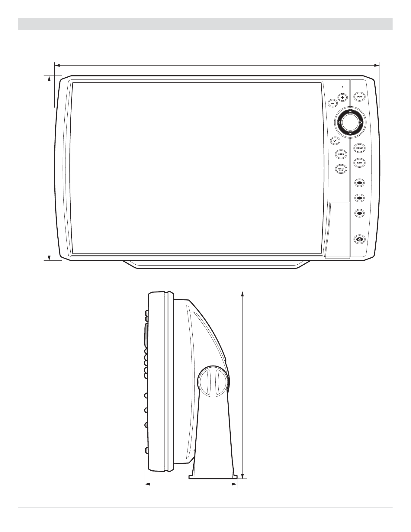
339
Specifications
HELIX 12 Control Head Measurements
HELIX 12 Gimbal Mount
14.86
||
(377 mm)
8.52
||
(216 mm)
4.11
||
(104 mm)
8.90
||
(228 mm)
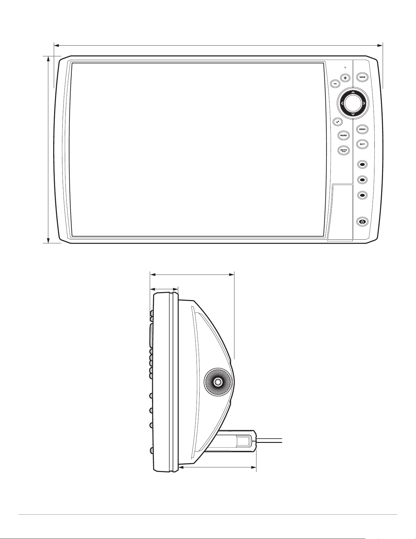
340
Specifications
HELIX 12 In-Dash Mount
14.86
||
(377 mm)
8.52
||
(216 mm)
3.69
||
(94 mm)
3.90
||
(99 mm)
1.22
||
(31 mm)

341
Specifications
HELIX 15 CHIRP MEGA DI+ GPS G4N
Control Head
Display Size (diagonal) ...............................................................................
15.4 inches (391.2 mm)
Pixel Matrix ............................................................................................. WXGA 800V x 1280H
Display Type ...................................................................................................... TFT Color
Backlight .............................................................................................................. LED
Communication .......................................................... Blueooth, NMEA 0183, NMEA 2000, Ethernet, Wireless
Power Input ................................................................................................... 10 to 20 VDC
Current Draw ......................................................................................................... 3.5 A
IPX Rating ................................................................. IPX7 Waterproof/Submersible @ 1 m for 30 minutes
Bluetooth Frequency Range ................................................................................ 2402 to 2480 MHz
Bluetooth Output Power ...................................................................................... 10 dBm Typical
CHIRP MEGA Down Imaging+ Transducer
XM 9 HW MDI T (includes built-in temperature probe)
Down Imaging
Operating Frequency ................................................................................. 455 kHz, 800 kHz, MEGA
Depth Capability ..................................................................................... 455 kHz: 400 ft (122 m)
800 kHz: 125 ft (38m)
MEGA: 200 ft (61 m)
Area of Coverage ............................................................................455 kHz: 75° @ -10 dB in 455 kHz
800 kHz: 45° @ -10 dB in 800 kHz
MEGA: 75° @ -10 dB in MEGA kHz
Power Output (MAX) .............................................................. 500 Watts (RMS), 4000 Watts (Peak to Peak)
Dual Spectrum
Default Operating Frequency ............................................................................... 150 kHz - 220 kHz
Depth Capability ............................................................................................ 1200 ft (366 m)
Area of Coverage ............................................................................ Full: 42°@-10 dB in 150-220 kHz
Wide: 42°@-10 dB in 140-200 kHz
Narrow: 25°@-10 dB in 180-240 kHz
Power Output (MAX) .............................................................. 500 Watts (RMS), 4000 Watts (Peak to Peak)
NOTE: Humminbird verifies maximum stated depth in saltwater conditions, but actual depth performance may vary due to
transducer installation, water type, thermal layers, bottom composition, and slope.
NOTE: Product specifications and features are subject to change without notice.

342
Specifications
HELIX 15 CHIRP MEGA SI+ GPS G4N
Control Head
Display Size (diagonal) ...............................................................................
15.4 inches (391.2 mm)
Pixel Matrix ............................................................................................. WXGA 800V x 1280H
Display Type ...................................................................................................... TFT Color
Backlight .............................................................................................................. LED
Communication .......................................................... Blueooth, NMEA 0183, NMEA 2000, Ethernet, Wireless
Power Input ................................................................................................... 10 to 20 VDC
Current Draw ......................................................................................................... 3.5 A
IPX Rating ................................................................. IPX7 Waterproof/Submersible @ 1 m for 30 minutes
Bluetooth Frequency Range ................................................................................ 2402 to 2480 MHz
Bluetooth Output Power ...................................................................................... 10 dBm Typical
CHIRP MEGA Side Imaging+ Transducer
XM 9 HW MSI T (includes built-in temperature probe)
Side Imaging
Operating Frequency ................................................................................. 455 kHz, 800 kHz, MEGA
Depth Capability ..................................................................................... 455 kHz: 800 ft (244 m)
800 kHz: 250 ft (76 m)
MEGA: 400 ft (122 m)
Area of Coverage ........................................................................... 455 kHz: 86° @ -10 dB in 455 kHz
800 kHz: 86° @ -10 dB in 800 kHz
MEGA: 86° @ -10 dB in MEGA kHz
Power Output (MAX) .............................................................. 500 Watts (RMS), 4000 Watts (Peak to Peak)
Down Imaging
Operating Frequency ................................................................................. 455 kHz, 800 kHz, MEGA
Depth Capability ..................................................................................... 455 kHz: 400 ft (122 m)
800 kHz: 125 ft (38 m)
MEGA: 200 ft (61 m)
Area of Coverage ........................................................................... 455 kHz: 75° @ -10 dB in 455 kHz
800 kHz: 45° @ -10 dB in 800 kHz
MEGA: 75° @ -10 dB in MEGA kHz
Power Output (MAX) .............................................................. 500 Watts (RMS), 4000 Watts (Peak to Peak)

343
Specifications
Dual Spectrum
Default Operating Frequency ............................................................................... 150 kHz - 220 kHz
Depth Capability ............................................................................................ 1200 ft (366 m)
Area of Coverage ............................................................................ Full: 42°@-10 dB in 150-220 kHz
Wide: 42°@-10 dB in 140-200 kHz
Narrow: 25°@-10 dB in 180-240 kHz
Power Output (MAX) .............................................................. 500 Watts (RMS), 4000 Watts (Peak to Peak)
NOTE: Humminbird verifies maximum stated depth in saltwater conditions, but actual depth performance may vary due to
transducer installation, water type, thermal layers, bottom composition, and slope.
NOTE: Product specifications and features are subject to change without notice.
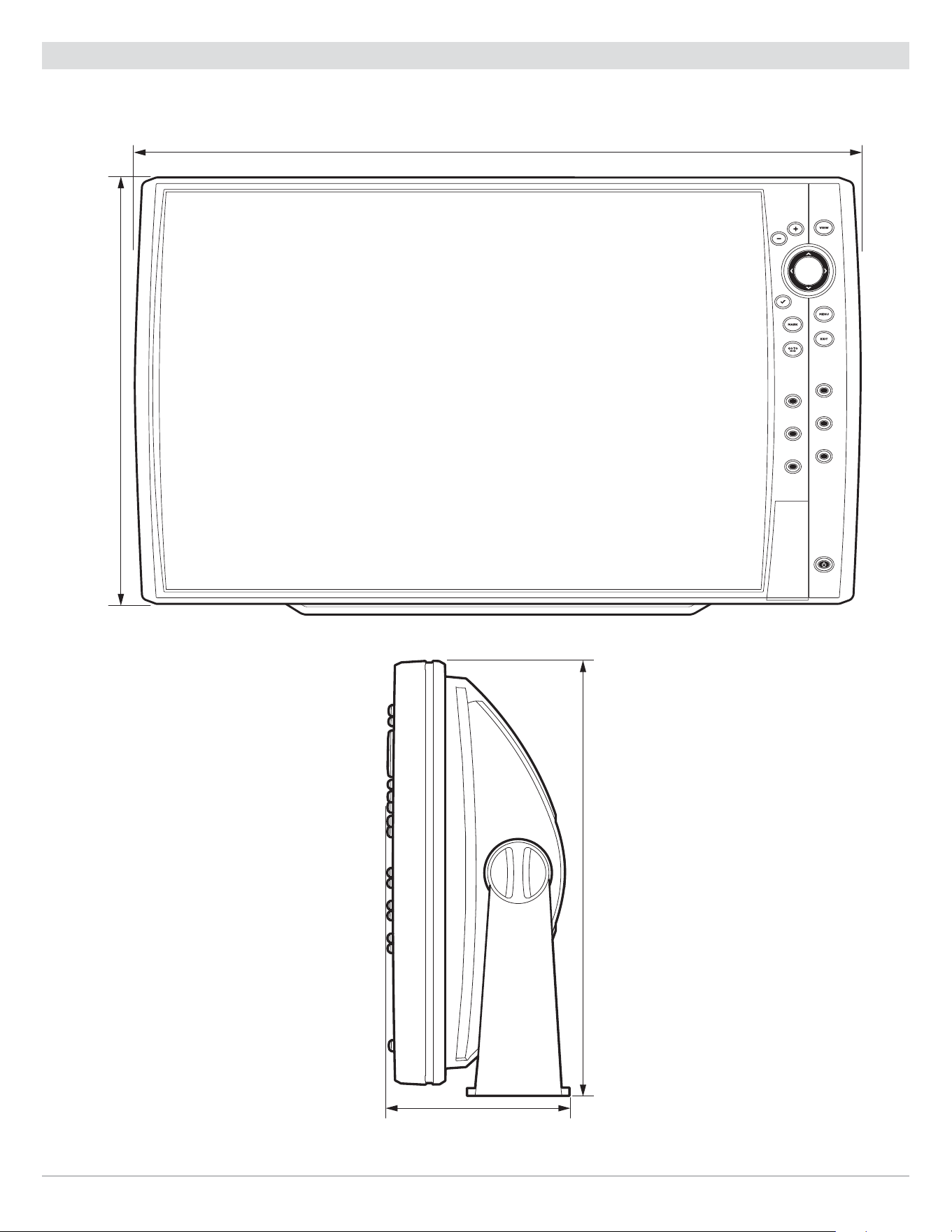
344
Specifications
HELIX 15 Control Head Measurements
HELIX 15 Gimbal Mount
17.63
||
(447.80 mm)
10.35
||
(262.89 mm)
4.44
||
(112.78 mm)
10.62
||
(269.75 mm)
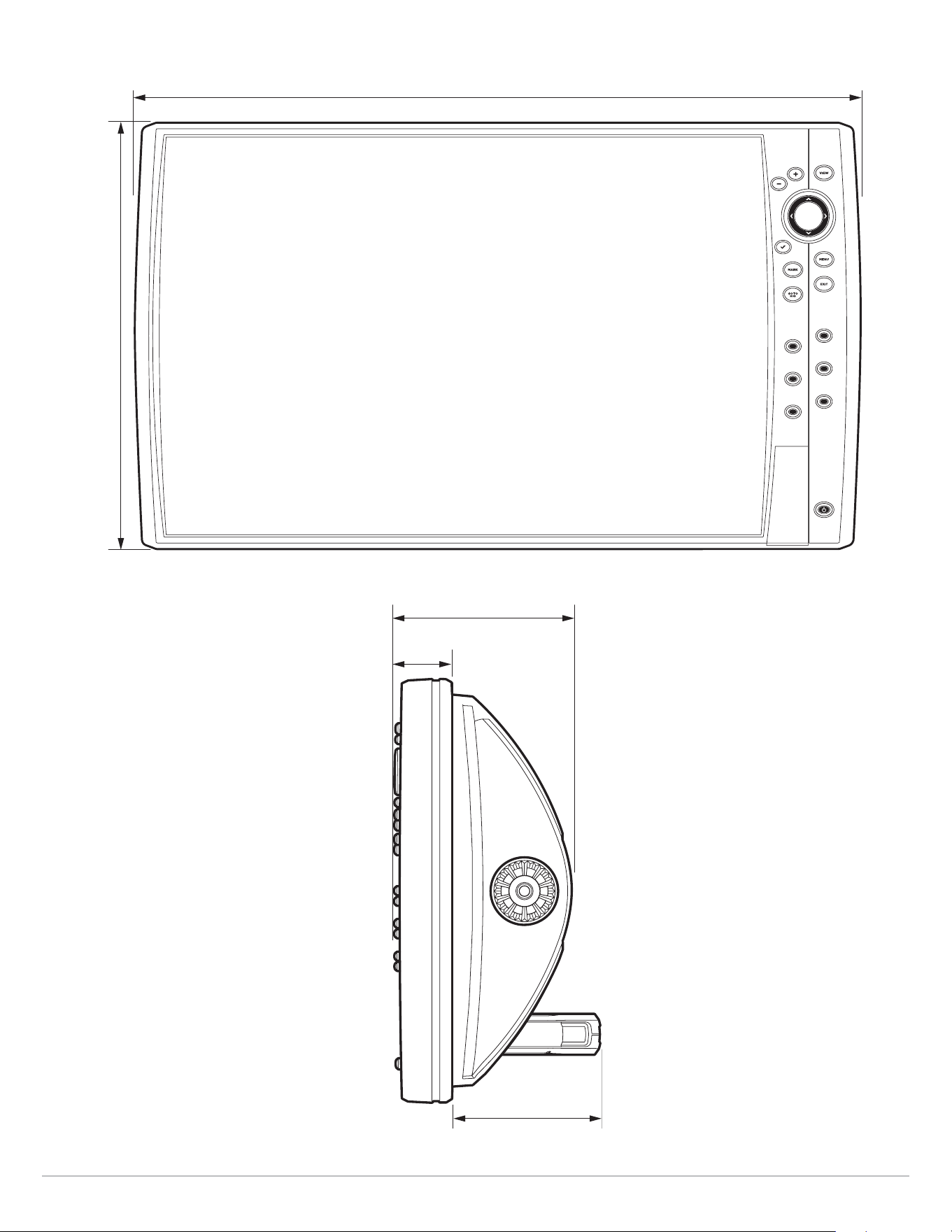
345
Specifications
HELIX 15 In-Dash Mount
17.63
||
(447.80 mm)
10.35
||
(262.89 mm)
3.62
||
(91.95 mm)
4.36
||
(110.74 mm)
1.42
||
(36.10 mm)

346
Statements and Acknowledgements
Statements and Acknowledgements
ENVIRONMENTAL COMPLIANCE STATEMENT: It is the intention of Johnson Outdoors Marine Electronics, Inc. to be a responsible corporate
citizen, operating in compliance with known and applicable environmental regulations, and a good neighbor in the communities where we
make or sell our products.
WEEE DIRECTIVE: EU Directive 2002/96/EC “Waste of Electrical and Electronic Equipment Directive (WEEE)” impacts most distributors, sellers,
and manufacturers of consumer electronics in the European Union. The WEEE Directive requires the producer of consumer electronics to take
responsibility for the management of waste from their products to achieve environmentally responsible disposal during the product life cycle.
WEEE compliance may not be required in your location for electrical & electronic equipment (EEE), nor may it be required for EEE designed and
intended as fixed or temporary installation in transportation vehicles such as automobiles, aircraft, and boats. In some European Union member
states, these vehicles are considered outside of the scope of the Directive, and EEE for those applications can be considered excluded from the
WEEE Directive requirement.
This symbol (WEEE wheelie bin) on product indicates the product must not be disposed of with other household refuse. It must be disposed
of and collected for recycling and recovery of waste EEE. Johnson Outdoors Marine Electronics, Inc. will mark all EEE products in accordance
with the WEEE Directive. It is our goal to comply in the collection, treatment, recovery, and environmentally sound disposal of those
products; however, these requirements do vary within European Union member states. For more information about where you should
dispose of your waste equipment for recycling and recovery and/or your European Union member state requirements, please contact your dealer
or distributor from which your product was purchased.
Linux Operating System
NOTE: This product uses the Linux operating system. This portion of the software is free software; you can redistribute it and/or modify it under
the terms of the GNU General Public License as published by the Free Software Foundation; either version 2 of the License, or (at your option)
any later version. This program is distributed in the hope that it will be useful, but WITHOUT ANY WARRANTY; without even the implied warranty
of MERCHANTABILITY or FITNESS FOR A PARTICULAR PURPOSE. See the GNU General Public License for more details.
You may receive a copy of the GNU General Public License along with this program; if not, write to the Free Software Foundation, Inc.,
51 Franklin Street, Fifth Floor, Boston, MA 02110-1301 USA.
To receive a free copy of the Linux software used in this system, please send a letter of request* with the following information:
Name (First & Last)
Phone Number
E-mail Address
Mailing Address
Humminbird serial number
(Your Humminbird unit must be registered at humminbird.com/support/productregistration.aspx.)
Shipping and Handling:
We can only accept requests that include a money order in the amount of $9.99 to cover shipping and handling. Please allow 4-6 weeks for
processing.
Send the letter of request* to the following address:
Software Request
Humminbird
678 Humminbird Lane
Eufaula, AL 36027
* NOTE: A copy of the Linux operating system is not required to upgrade your fishing system. The Humminbird application software and control
head include a separate service warranty. Please see humminbird.com and the separate warranty card included with your unit for details.
347
Statements and Acknowledgements
FCC Notice
This device complies with Part 15 of the FCC Rules. Operation is subject to the following two conditions: (1) this device may not cause harmful
interference, and (2) this device must accept any interference received, including interference that may cause undesired operation.
CAUTION! This equipment has been tested and found to comply with the limits for a Class B digital device, pursuant to Part 15 of the FCC
Rules. These limits are designed to provide reasonable protection against harmful interference in a residential installation. This equipment
generates, uses and can radiate radio frequency energy and, if not installed and used in accordance with the instructions, may cause
harmful interference to radio communications. However, there is no guarantee that interference will not occur in a particular installation.
If this equipment does cause harmful interference to radio or television reception, which can be determined by turning the equipment off
and on, the user is encouraged to try to correct the interference by one or more of the following measures:
• Reorient or relocate the receiving antenna.
• Increase the separation between the equipment and receiver.
• Connect the equipment into an outlet on a circuit different from that to which the receiver is connected.
• Consult the dealer or an experienced radio/TV technician for help.
RF EXPOSURE COMPLIANCE: This device has been evaluated and found compliant in accordance with EU EN 62479:2010 and EN 62311:2008 for
human RF exposure.
This product has been so constructed that the product complies with the requirement of Article 10(2) as it can be operated in at least one Member
State as examined and the product is compliant with Article 10(10) as it has no restrictions on putting into service in all EU member states.
EU DECLARATION OF CONFORMITY: Hereby, Humminbird declares that this device is in compliance with the essential requirements and other relevant
provisions of Directive 2014/53/EU. The declaration of conformity may be consulted at https://www.humminbird.com/Category/Support/FAQ/EU_DoC/.
UK DECLARATION OF CONFORMITY: Hereby, Humminbird declares that this device is in compliance with the essential requirements and other
relevant provisions of Radio Equipment Regulations 2017.
Class B Device (Broadcasting and communication equipment for home)
This equipment is home use (Class B) electromagnetic wave suitability equipment and to be used at home and it can be used in all areas.
End User License Agreement
This Hydrographic Database is the proprietary and confidential property of Johnson Outdoors Marine Electronics. Unauthorized use, including
the copying of this Hydrographic Database, is expressly prohibited. BY USING THE PRODUCT YOU ARE AGREEING TO BE BOUND BY ALL THE TERMS
AND CONDITIONS OF THE JOHNSON OUTDOORS (“LICENSOR”) LICENSE AGREEMENT (“AGREEMENT”) WHICH IS PROVIDED WITH THIS COASTMASTER
AND/OR LAKEMASTER DIGITAL MAP PRODUCT (“LICENSED PRODUCT”) INCLUDING, WITHOUT LIMITATION, THE USE RESTRICTIONS, WARRANTY
DISCLAIMER AND LIMITATIONS OF LIABILITY SET FORTH HEREIN. Under the Agreement, you have a limited, non-exclusive, personal license to
use the data contained on the media in this package, on a GPS mapping device for supplemental navigation reference purposes. Licensor and
its third-party suppliers retain all rights to the Licensed Product not expressly granted by the Agreement. You are responsible for using official
government charts and prudent navigation for safe travel. The Licensed Product and the accompanying documentation are copyrighted works of
authorship and contain valuable secret and confidential information proprietary to Licensor and its third-party suppliers who retain the ownership
of the information and all copyrights and other proprietary rights therein. You agree to exercise reasonable efforts to protect their proprietary
interests. You may NOT modify, adapt, translate, reverse engineer, decompile, disassemble, sub license, rent, lease, or sell any portion of the
Data. You may NOT create derivative works based upon the Data. You may NOT place the Data onto a server so that it is accessible via a public
network such as the Internet.
LICENSOR AND ITS THIRD-PARTY SUPPLIERS DO NOT WARRANT THE LICENSED PRODUCT WILL MEET YOUR REQUIREMENTS OR THAT ITS OPERATION
WILL BE UNINTERRUPTED OR ERROR-FREE. IN NO EVENT WILL COASTMASTER, LAKEMASTER OR ITS SUPPLIERS BE LIABLE TO YOU FOR ANY
CONSEQUENTIAL OR INCIDENTAL DAMAGES. Some states or jurisdictions do not allow the exclusion or limitation of consequential or incidental
damages, so the above limitations may not apply to you.
Portions of Humminbird Basemap OpenStreetMap contributors. Portions of Humminbird Basemap sourced from GeoBase®.
Portions of Humminbird Basemap contains information licensed under the Open Government Licence Canada. Portions of Humminbird Basemap
copyright 2001 Her Majesty the Queen in Right of Manitoba, as represented by the Minister of Conservation. All rights reserved. Portions of
Humminbird Basemap contains information licenced under the GeoNB Open Data Licence. Portions of Humminbird Basemap contains information
licenced under the Open Government Licence Ontario.

348
Contact Humminbird
Contact Humminbird Technical Support in any of the following ways:
Web site:
humminbird.com
E-mail:
Telephone:
1-800-633-1468
Direct Shipping:
Humminbird
Service Department
678 Humminbird Lane
Eufaula, AL 36027 USA
Hours of Operation:
Monday - Friday
8:00 a.m. to 4:30 p.m. (Central Standard Time)
Social Media Resources:
Facebook.com/HumminbirdElectronics
Twitter.com (@humminbirdfish)
Instagram.com/humminbird
YouTube.com/humminbirdtv