Loading ...
Loading ...
Loading ...
8
PREPARE THE LOCATION
NOTE
Before making cutouts, make sure there is
proper clearance within the ceiling or wall.
Disconnect power.
Selectaatsurfaceforassemblingtherangehood.
Place covering over that surface.
Lift the range hood and set it upside down onto covered
surface.
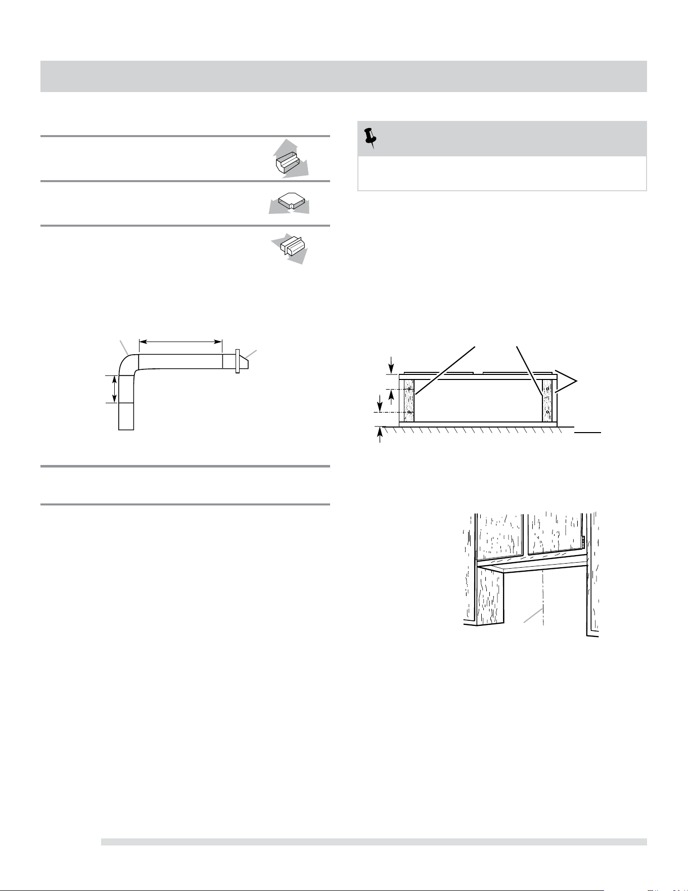
Ifcabinethasrecessedbottom,addwoodllerstrips
oneachside.Installscrewstoattachllerstripsin
locations shown.
Determine Wiring Hole Location
Determine and clearly mark a vertical centerline on
the wall and cabinet bottom.
1.
2.
3.
4.
1.
A
A Centerline
Wood filler strips
(recessed cabinet
bottoms only)
Wall
Cabinet
bottom
3” (7.6 cm)
3” (7.6 cm)
4.5x13mm
mounting screws
VENTING REQUIREMENTS
3¼” x 10” (8.3 cm x 25.4 cm) Vent System
Vent Piece
3¼”x10”(8.3cmx25.4cm) 5.0ft
90° elbow (1.5 m)
3¼”x10”(8.3cmx25.4cm) 12.0ft
flat elbow (3.7 m)
3¼”x10”(8.3cmx25.4cm) 0.0ft
wall cap (0.0 m)
Example Vent System
MaximumRecommendedLength =35ft(10.7m)
1-90°elbow =5.0ft(1.5m)
8ft(2.4m)straight =8.0ft(2.4m)
1-wallcap =0.0ft(0.0m)
Length of 3¼”x10” =13.0ft(3.9m)
(8.3cmx25.4cm)system
2 ft
(0.6 m)
3¼”x10”
(8.3x25.4cm)
elbow
6 ft (1.8 m)
Wall Cap
Loading ...
Loading ...
Loading ...