PORTABLE CAR LIFT 2.25 TONNE 750W/230V
MODEL NO: CLM2250
Thank you for purchasing a Sealey product. Manufactured to a high standard, this
product will, if used according to these instructions, and properly maintained, give you
years of trouble free performance.
IMPORTANT: PLEASE READ THESE INSTRUCTIONS CAREFULLY. NOTE THE SAFE OPERATIONAL REQUIREMENTS, WARNINGS & CAUTIONS. USE
THE PRODUCT CORRECTLY AND WITH CARE FOR THE PURPOSE FOR WHICH IT IS INTENDED. FAILURE TO DO SO MAY CAUSE DAMAGE AND/OR
PERSONAL INJURY AND WILL INVALIDATE THE WARRANTY. KEEP THESE INSTRUCTIONS SAFE FOR FUTURE USE.
1. SAFETY
9 Read all warnings, safety instructions and other instructions. Failure to follow all the instructions and safety
instructions can result in a risk of personal injury and/or material damage.
9 Thelifthastobeusedonlyreferringtothetypeofvehiclesupportspeciedbythemanufacturer.
9 The manufacturer assumes no responsibility for personal injury or damage to property arising from the handling,
use or maintenance of the product in any way other than that described in these instructions.
9 Special training has to be given to the operator and the persons who are permitted to stand under the vehicle during lifting and
lowering. Only to be used by operators who have been trained to use it and those who are fully conversant with this manual.
9 Persons are only permitted to stand under a moving load in extreme circumstances where movements of the load should be kept as
short as possible.
WARNING! indicates a dangerous or potentially dangerous situation that could lead to fatal or serious personal injury if the instructions
are not followed.
IMPORTANT! indicates instructions that must be followed in order to prevent damage to property.
9 Familiarise yourself with the controls on the product and how to use them. Persons who are not trained or familiar, with these
instructions must not use the product.
9 Incorrect use can result in the risk of fatal or serious personal injury and/or material damage.
9 This product is a portable vehicle lift. Use the product only for its intended purpose.
9 Check the product for cracks in weld joints as well as damaged, loose, worn or missing parts each time before use.
9 Keep all body parts away from the product during use.
9 Never modify the product in any way.
9 In the event of oil spillage ensure an oil spill kit is to hand. Consult Sealey website for Materials Safety Data Sheet for characteristics
ofuidsincludedwiththeproduct.
9 Fireghtingprocedure/equipmentshouldbeinaccordancewiththeMaterialsSafetyDataSheet.
9 Only use lifting points recommended by the vehicle manufacturer.
9 After installation the name plate shall remain readily visible.
9 After installation at the user’s site check that the vehicle lift and the associated safety and protective devices are correctly installed and
function in a proper manner.
9 Always check the weight of the vehicle before lifting. Never exceed the maximum permitted load for the product.
9 Overloading damages the products and entails a risk of serious personal injury.
9 Never adjust the safety valve.
9 Inspect the product carefully at least once a year. Replace any damaged or worn cables and hoses. Check that the safety and warning
labels on the product are intact and legible. Replace any labels that are illegible or have gone missing.
8 DO NOT use the product until any worn or damaged parts have been replaced.
8 Never attempt to lift loads that are not centred or are poorly balanced. Incorrect loading can damage the product and entails a risk of
serious personal injury.
9 Take steps to ensure that the load cannot move or tip over while being raised or lowered. If the product is being used beside a road,
traccancausethevehicletomove.
9 Make sure that nobody is inside the vehicle and apply the parking brake.
9 Secure the load that is to be lifted with wedges or similar, so that it cannot slide or move.
9 Never climb into a raised or supported vehicle and do not start the engine.
8 DO NOT touch hot parts – risk of getting burned.
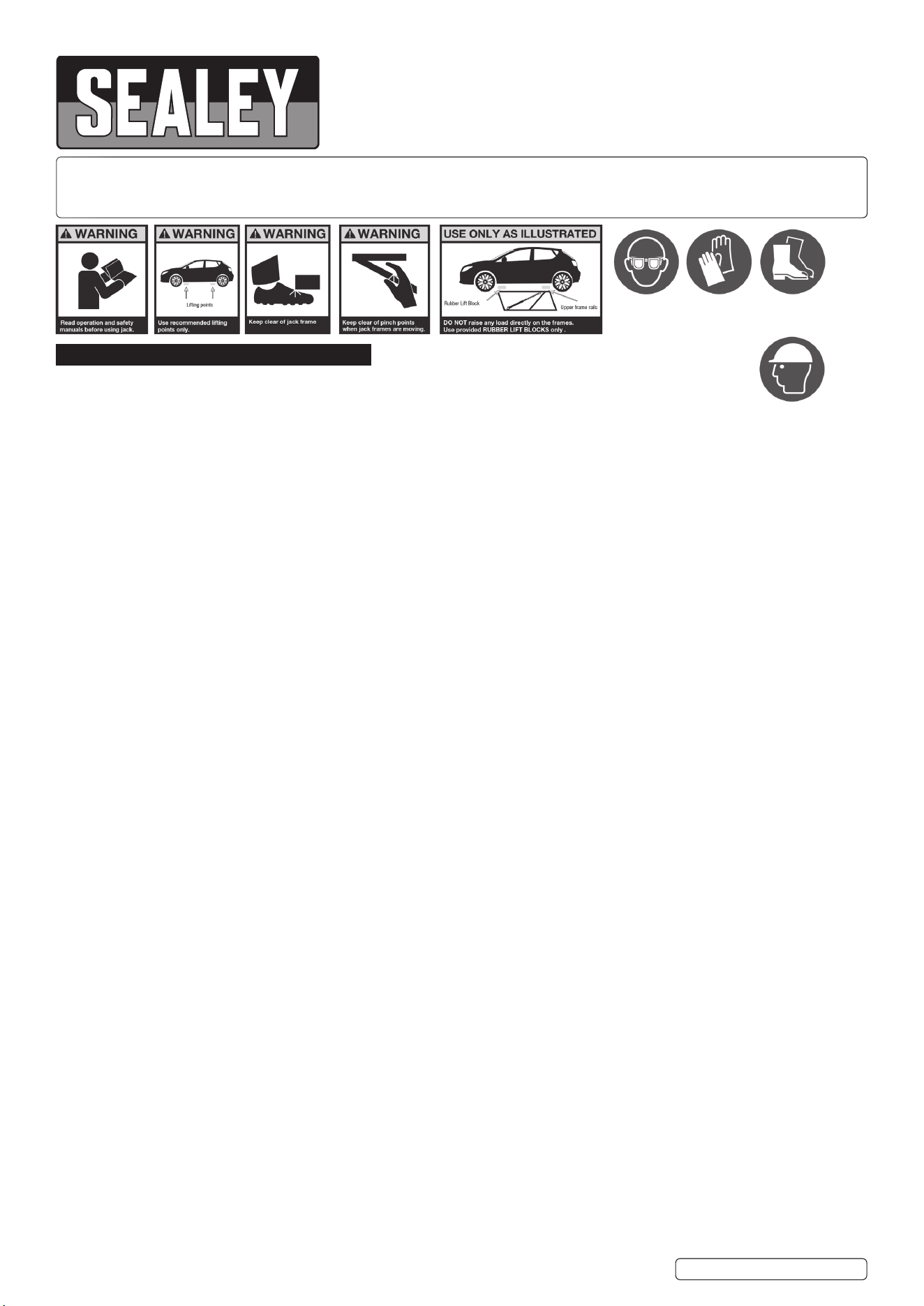
9 Wearsuitablepersonalprotectiveequipment,suchassafetyglasses,safetyhelmet,gloves,etc.
9 Thesurfacetheliftisusedon,mustbedry,atandabletosupportaloadof34.4bar.
9 Route the power cord and the hydraulic hoses so that they cannot be trodden on or driven over, so that there is no risk of tripping over
them, or of them being put under strain.
8 DO NOTwearloose-ttingclothing,jewellery,watches,etc.,thatcangetcaughtinmovingpartsorconductelectricity.
9 Evacuate the area immediately if the load is threatening to collapse the vehicle lift.
9 Check that both safety lock bars are applied before anyone goes in the vicinity of the raised load.
9 Neveropenthellerplugontheelectricpumpwhentheproductisinuse.
9 Contactyourstockistfortechnicalassistanceorrepairs.Thewarrantyceasestoapplyiftheproducthasbeenmodiedinanyway,
damaged as a result of an accident, negligence or incorrect use, or has been repaired by unauthorised personnel.
9 Always keep the product clean.
9 Store the product fully lowered when not in use.
8 DO NOT usehydraulicequipmentattemperaturesabove65°C.Hightemperaturesweakenthehosematerialandcausesealsto
soften,whichentailsariskofhydraulicuidleakageand/orotherdamagetoproperty.
CLM2250Issue:4(1)22/10/24
Original Language Version
© Jack Sealey Limited
Wear eye
protection
Wear
protective
gloves
Wear
protective
footwear
Wear head
protection
9 Make sure that no parts are damaged, missing or worn.
9 Checkforotherfactorsthatcouldaecttheoperationofthepowertool.Checkthattheliftingblocksareplacedontheplatesonthe
lifting frames. Never use the product if it is damaged or worn, or if it is not functioning normally.
8 DO NOT use the product before damaged or worn parts have been replaced.
Take it to an authorised service centre for inspection and possible repair.
9 Checkthattheworkareaisfreefromobjectsthatcouldaecttheraising/loweringofthevehicle.Alsocheckabovetheproduct.
Remove any obstructions. Check that there are no people or animals in the work area.
9 Familiarise yourself with the controls on the product and how to use them.
9 Persons who are not familiar with these instructions must not use the product. Nobody other than the user may be in the work area.
9 Ensure that everyone who is going to be in the vicinity of the product is aware of it and takes suitable precautions.
8 DO NOT interrupt lifting until one of the locking positions has been reached.
8 DO NOT interrupt lowering until the product has been completely lowered.
8 DO NOT allow children to use the product.
8 Neverusetheproductifyouaretiredorundertheinuenceofdrugs,alcoholormedication.
9 Never exceed the maximum permitted load for the product. Make sure that nobody is inside the vehicle that is to be lifted. Check that
thevehicleiswellbalancedatbothends.Onlyusetheliftingpointsspeciedbythevehiclemanufacturer.Neverliftonlyoneside,
one corner or one end of the vehicle.
9 Lower the raised vehicle in the nearest position to the ground level if the maximum permissible wind speed is exceeded and at the end
of working time.
9 Never pull the cable on the remote control or power cord to move the power unit, this can damage the cable.
9 Never pull the hydraulic hoses to move the lifting frames - this can damage the hoses.
9 Make sure to check the product at least once a year. Replace damaged or worn electric cables, hydraulic hoses, markings or warnings.
2. INTRODUCTION
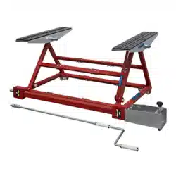
A transportable lifting system which makes total vehicle lifting, for maintenance or detailing, much more convenient. Each Strut weighs less than
40kg,andisonwheelsforeasypositioning.Automaticsafetylockbars,withduallockingpositions.Alowclearanceheightofjust75mm,making
it ideal for custom, sports and race vehicles.
3. SPECIFICATION
Model No: ...............................................................CLM2250
Capacity: ............................................................. 2.25tonnes
Weight: ...................................................................... 104.4kg
Sound: ...................................................................... <70dBA
Max. allowed wind speed during use: ......... <60mph/96.5kph
Fuse Rating: ...............................................................13amp
Lock Spacing: ..............................................237,77&48mm
Lock Positions: ...................................... 311,388and436mm
Plug Type: ......................................................................3-Pin
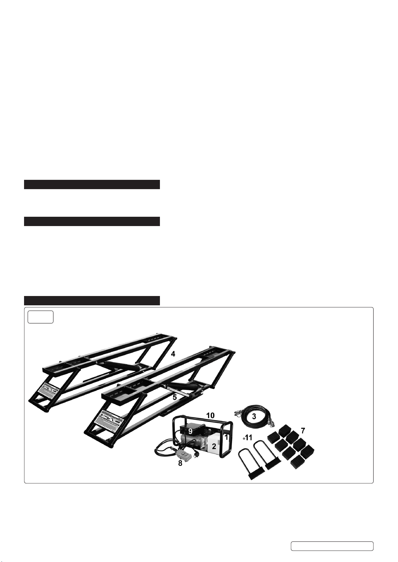
4. CONTENTS
1.Fillerplugforhydraulicuid
2.Hydraulicuidreservoir
3.Longhydraulichoseswithcouplers(X2)
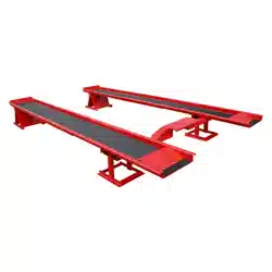
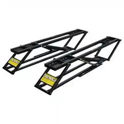
4.Liftingframes(X2)
5.Safetylockbar(X2)
6.Shorthydraulichoseswithcouplers(X2)(not
shown)
7.Rubberliftingblocks55mm(X4)and75mm(X4)
8.Remotecontrol
9.Hydraulicpowerunit
10.Positioninghandle
11.Sealplugforhydraulicreservoir
Original Language Version
© Jack Sealey Limited
fig.
1
CLM2250Issue:4(1)22/10/24
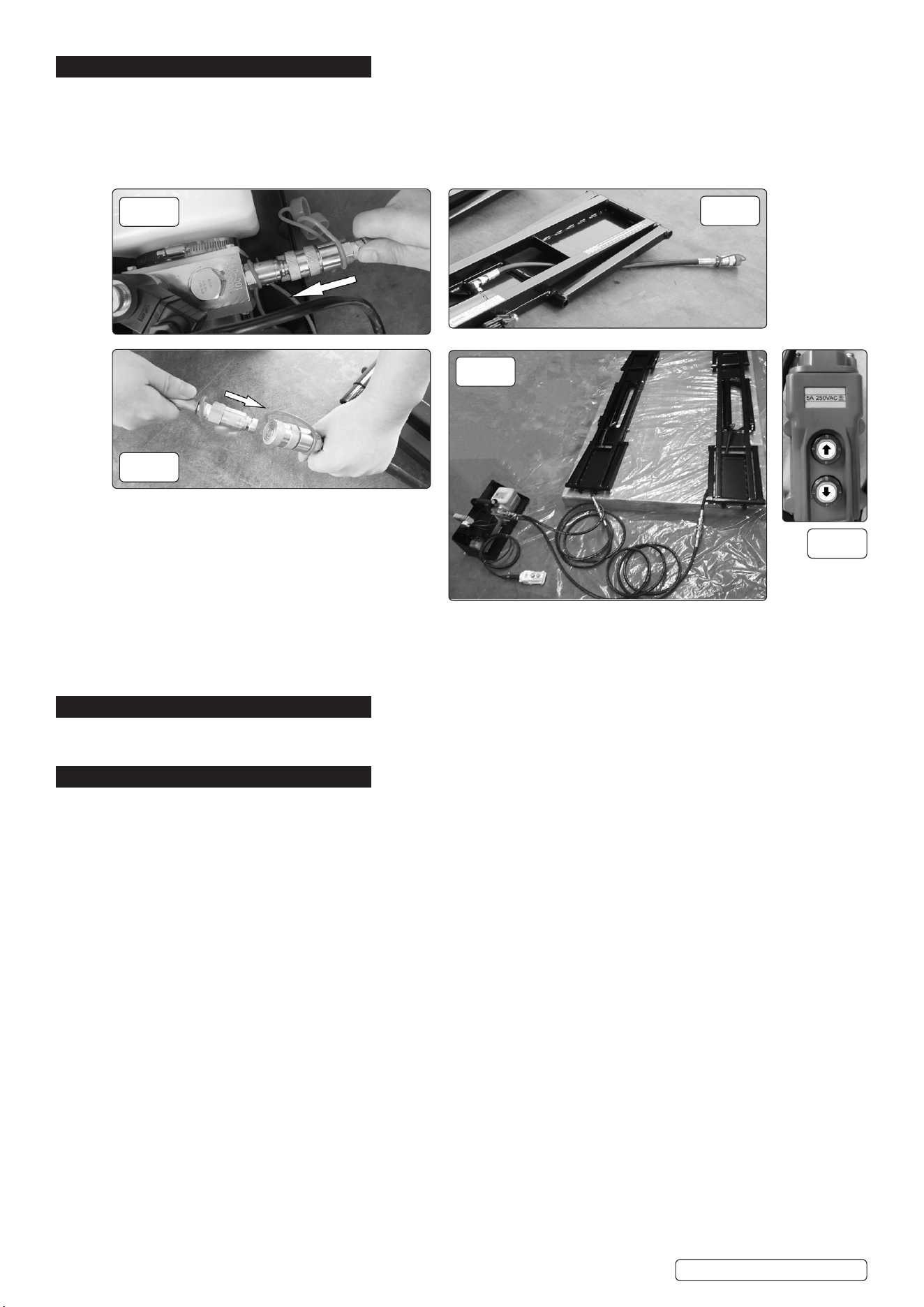
5. ASSEMBLY
5.1. Ondeliverythereisnohydraulicuidinthehydraulicuidreservoironthehydraulicpowerunit.Fillwithhydraulicuidbeforeusing
the product.
5.2. The short hydraulic hoses must be routed under the bottom of the lifting frames, never over the lifting frames.
5.3. Unscrewthellerplug(1)andllwith1.8litresofhydraulicuid(ISO32orISO46)inthehydraulicuidreservoir(2).Screw
the plug on.
5.4. Connect the Female couplers on the longhose(3)tothemalecouplersonthehydraulicpowerunit(9).FIG.2
5.5. Routetheshorthose(6)underthebottomoftheliftingframes(4),neverovertheliftingframes.FIG.3
5.6. Connectthemalecouplersonthelonghosestothefemalecouplersontheshorthose.FIG.4
5.7. Connect the power unit to the power supply.
5.8. Theliftsystemisnowreadytouse.FIG.5
5.9. PresstheUbutton(up)ontheremotecontrol(8)toltandtheDbutton(Down)tolower.FIG.6
6. PREPARATION: BLEEDING
6.1. Air may accumulate within the hydraulic system after assembly. It will cause the jack frame to shake during raising or lowering.
6.2. Raise and lower the lift a few times to bleed the air from the system. Once it raises and lowers without shaking, it is ready to use.
7. OPERATION
7.1. Read all the safety instructions and other instructions.
8 DO NOT exceed the maximum permitted load.
7.2. If the vehicle that is to be lifted is not correctly positioned, there is a risk of it falling, which could cause serious personal injury and/or
damage to property.
7.3. Check the product for cracks in weld joints as well as damaged, loose, worn or missing parts each time before use.
8 DO NOT use the product before replacing any worn or damaged parts.
7.4. Each time before lifting, check:
- that the lifting frames are correctly positioned under the vehicle and as parallel as possible
- that nobody is within the risk area
- that the lifting frames’ safety lock bars are turned outwards
- and that there are not obstacles around or above the vehicle.
7.5. Familiarise yourself with the product and its controls by raising and lowering it a few times without a load.
8 DO NOT lower the vehicle if wheels or tyres have been removed. There must be space between the ground and the load that is to be
lifted, in order to raise the lifting frames slightly before lifting the load.
The product cannot lift a full load from a fully lowered position.
7.6. For optimum load stability, always place the two lifting frames as parallel with each other as the vehicle’s lifting points permit.
7.7. Never attempt to drive the vehicle up onto the lift, as this will damage the lifting frames.
7.8. Never lift a vehicle directly on the lifting frames: always use lifting blocks.
7.9. Never leave the product unattended if it is not fully lowered or locked in the lower or upper locking position. Scissor lifts are designed
to only hold loads with lock bar applied in the locking positions.
7.10. Only use lifting blocks of the same height, do not mix low and high lifting blocks.
Original Language Version
© Jack Sealey Limited
fig.
3
fig.
2
fig.
4
fig.
5
fig.
6
CLM2250Issue:4(1)22/10/24
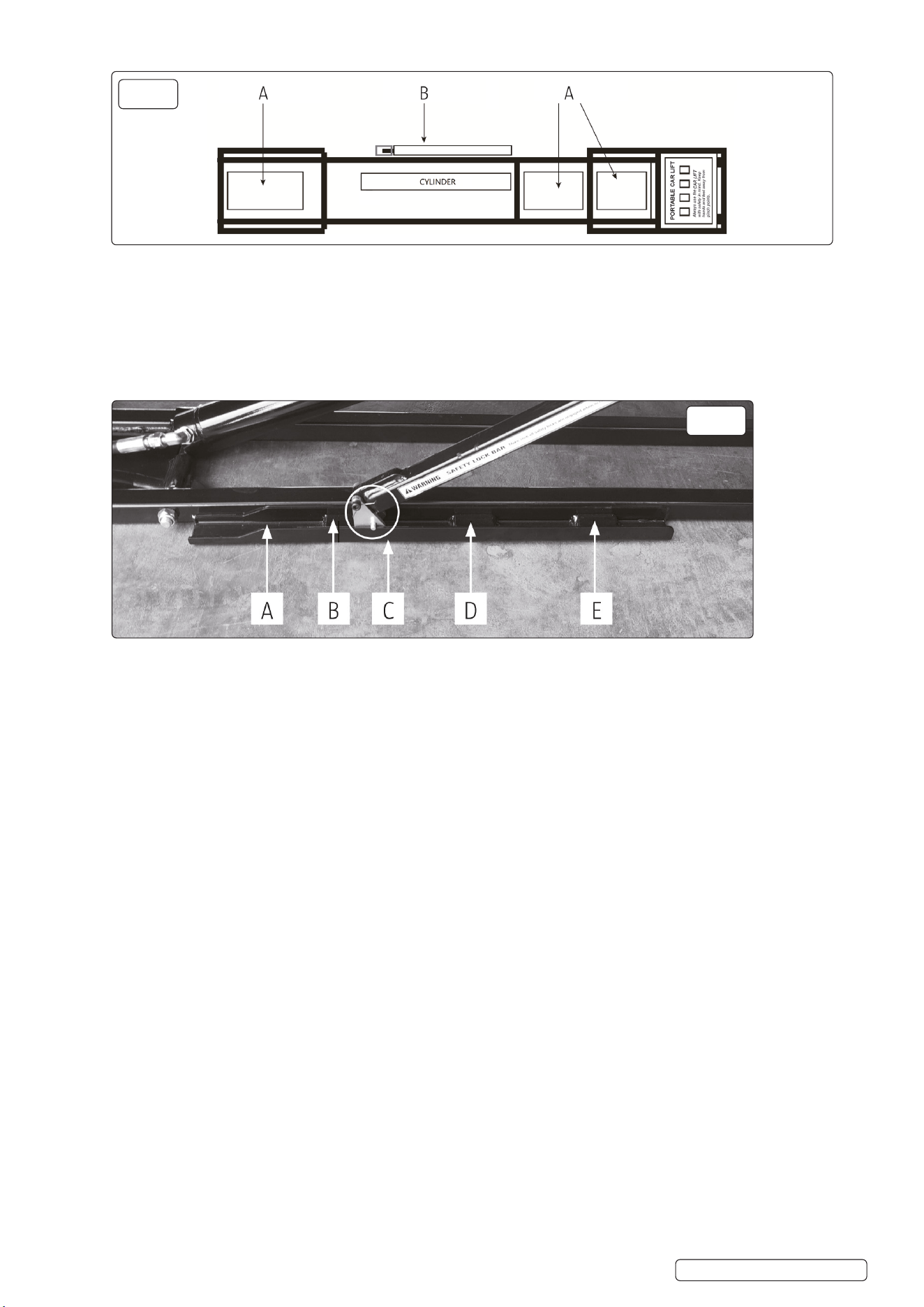
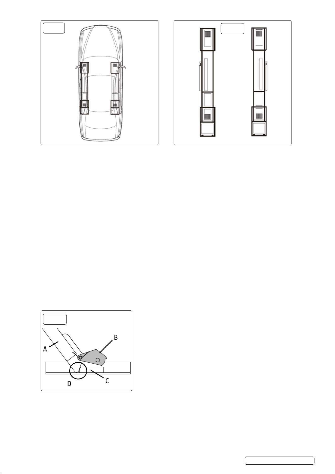
7.11. LIFTING BLOCKS
7.11.1. Fig.A Tray for lifting blocks.
7.11.2. Fig.BSafetylockbar:mustbeontheoutside.
7.12. LOCK POSITION
7.12.1. This lift system has three locking positions:
A. Tracks.
B.Lowerlockingposition.
C. The turning block MUST remain in the tracks.
D. Middle locking position.
E. Upper locking position
7.13. POSITIONING THE LIFTING FRAMES
WARNING! DO NOT drive the vehicle onto the lifting frames.
7.13.1. The lifting frames can be positioned under the vehicle in the following two ways: from the outside in and from the inside out.
7.13.2. From the outside in:
Park the vehicle in the desired location and align the lifting frames between the wheels along the vehicle’s sides.
Ifthedistancebetweenthewheelsistooshortfortheretoberoomfortheliftingframes,turntheliftingframesandrstpushinone
end and then the other.
Check that the safety lock bars are facing out.
Move the lifting frames to the desired positions under the vehicle.
Avoid driving over the hydraulic hoses.
7.13.3. From the inside out:
Put the lifting frames beside each other.
Check that the safety lock bars are facing out.
Run forward the vehicle so that the lifting frames are midway under the vehicle.
Avoid driving over the hydraulic hoses.
Move the lifting frames to the desired location at the vehicle’s lifting points.
7.14. POSITIONING THE LIFTING FRAMES UNDER THE VEHICLE
7.14.1. Before positioning the lifting frames, check that both lifting frames are fully lowered and that the work area is free from obstacles.
7.14.2. Check that the vehicle is well balanced and cannot tip in any direction.
7.14.3. Never lift a load directly on the lifting frames – always use lifting blocks.
7.14.4. Determine the desired method for placing the lifting frames under the vehicle.
7.14.5. Place lifting blocks of the same thickness on the lifting frames’ plates.
7.14.6. Place the lifting frames in a suitable place in relation to the lifting points on the vehicle.
7.14.7. Adjust the lifting blocks on the plates so that they are directly beneath the vehicle’s lifting points.
7.14.8. In this way, lifting frames and lifting blocks are correctly positioned to lift the vehicle.
IMPORTANT: The lifting frames must be parallel under the vehicle.
Original Language Version
© Jack Sealey Limited
fig.
8
fig.
7
CLM2250Issue:4(1)22/10/24
7.15. SAFETY LOCKBARS
7.15.1. Oneachliftingframethereisalockbarthatisusedtolocktheframeintherequiredposition.
8 DO NOT leave the product unattended if is not fully lowered or locked in one of the three locked positions.
7.15.2. Always check before use, that the lock bar move easily and remain in their tracks.
7.15.3. The product will not work correctly if the lock bars become stuck in their upper positions or are not located in their tracks.
7.16. LIFTING
7.16.1. Press and hold the U button on the remote control. The lifting frames are raised.
7.16.2. Release the U button just before the lifting block comes into contact with the vehicle’s lifting points. The lifting frames stop moving.
7.16.3. Check that the lifting blocks are correctly aligned in relation to the vehicle’s lifting points.
7.16.4. Adjust the lifting blocks, if necessary. The vehicle may need to be lowered slightly in order for the lifting blocks to be able to be moved.
7.16.5. Press the U button on the remote control again to continue lifting.
WARNING! DO NOT stop lifting until the lifting frames have passed the lower locking position.
7.16.6. Release the U button to stop lifting immediately after the lower locking position, even if you are going to continue lifting to the upper
locking position.
7.16.7. Check that the lifting blocks are located at the vehicle’s lifting points. If the lifting blocks are correctly positioned, continue lifting. If
the lifting blocks are not correctly positioned, press the D button on the remote control to lower the vehicle. Make the necessary
adjustments.
7.16.8. Check that the vehicle is correctly balanced. If it is, continue lifting. If the vehicle is not correctly balanced, press the D button on the
remote control to lower the vehicle. Make the necessary adjustments.
7.16.9. Liftthevehiclealittlewaypastthedesiredlockingposition(lowerorupper).
7.16.10. Release the U button and press the D button to lower the vehicle to the locking position. The lowering of the lifting frames is
interrupted by locking.
7.16.11. Check visually that both lifting frames have been locked at the same locking position.
A. Lock bar
B.Turningblock
C. Lock block
D. Locked position
WARNING!
Beforestartingworkonthevehicleorleavingthearea,checkvisuallythatboththeliftingframesarelockedinthesamelocking
position and that all the lifting blocks are in contact with the vehicle’s lifting points. Work on the vehicle can be performed when both
the lifting frames are locked in the same locking position and all the lifting blocks are in contact with the vehicle’s lifting points.
7.17. LOWERING THE FRAMES FROM THE LOCKING POSITION
WARNING! When lowering car lift jack frames, make sure the lock bar and the turning blocks stay in their tracks. If they get knocked
sideways, for example, they can get stuck on the rail of the track, which could result in the car lift not lowering correctly.
7.17.1. Press and hold U button until the lock bar is clear of the lock block.
Original Language Version
© Jack Sealey Limited
fig.
11
fig.
9
fig.
10
CLM2250Issue:4(1)22/10/24
7.17.2. Lift the lock bar on both car lift jack frames so that the turning block is on top of the lock block on both frames. You can use a tool
to lift the lock bar.
7.17.3. Press down on the remote control. Make sure the lock bars clear the lock block on
both car lift jack frames on their way down. Release the down button if either side
does not clear the lock block.
7.17.4. Continue pressing down button until both car lift jack frames are lowered to the ground.
NOTE:
7.17.5. Press down button for a few seconds after the frames are on the ground. This ensures
thatasmuchhydraulicuidaspossiblereturnstotheuidreservoir.
7.17.6. Remove the car lift jack frames from underneath the vehicle, use the jack
frame handles.
7.17.7. Move the vehicle. DO NOT drive the vehicle over the car lift jack frames or
the hydraulic hoses.
8. MAINTENANCE
WARNING! Remove from the mains power supply and relieve the hydraulic pressure prior to maintenance and/or cleaning.
8.1. Ageneralevaluationoftheresiduallife-timeoftheproductistobedoneatlatestafter10yearsofuse,byaqualiedtechnician,
preferably authorized by the manufacturer.
8.2. CLEANING
8.2.1. Clean all parts regularly for optimum functionality and service life.
8.2.2. Usesuitablepersonalprotectiveequipmentwhenworkingwiththehydraulicsystem.
8.2.3. Avoidskincontactwithhydraulicuid.Followthemanufacturer’ssafetyinstructions.
8.3. TRANSPORTATION
8.3.1. Transportation with hydraulic oil by car or truck:replacethellerplug(1)ontheuidreservoirbythesealplug(11).Thellerplug
cannotsealtheuidinthereservoir,itwillcausethehydraulicoiltoslopoutfromthereservoirduringtransportation.
8.3.2. Iftheunitneedstobetransportedviaalogisticscompanyemptytheuidinthereservoirbeforehand.
8.3.3. Rememberbeforeusetoremovethesealplug(11)andreplaceitwiththellerplug(1).
8 DO NOTusethesealplug(11)whenusingthepowerunit,itwilldamagetheuidreservoir.
8.3.4. If the unit is to be moved release the long hydraulic hoses from the power unit, move the pump separately from the lifting frame and
hoses.
8.4. STORAGE
8.4.1. Store in fully lowered position when not in use.
8.5. REPAIR
8.5.1. Professional repair only. Contact Sealey for Technical Assistance.
8.5.2. Warrantywillbeinvalidatediftheproductismodiedinanyway,damagedasaresultofanaccident,negligenceorincorrectuse,orif
it has been repaired by unauthorised personnel.
8.6. SAFETY CHECKS
8.6.1. Check all bolted joints regularly, and tighten them if necessary.
8.6.2. Check the product for cracks in weld joints as well as damaged, loose, worn or missing parts each time before use. DO NOT use the
product until any worn or damaged parts have been replaced.
8.6.3. Check that the Safety lock bars are in good condition and working properly. Do not use the product if the Safety lock bars are damaged
or worn.
8.6.4. Check the lifting blocks and replace them if they are damaged or worn.
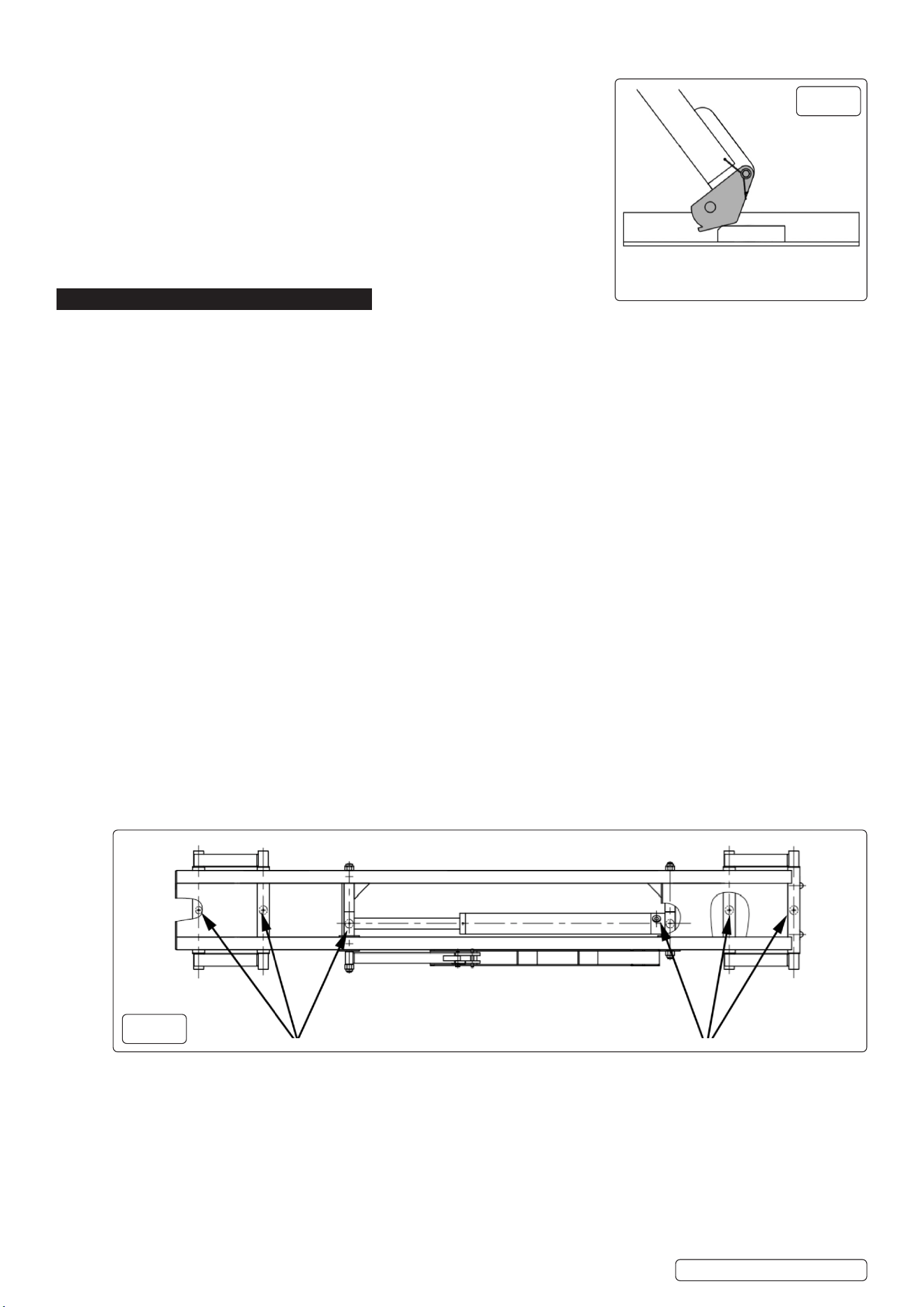
8.6.5. MONTHLY:
Lubricatealljointsandcheckforwear.Ifnecessarylubricatewithwhitelithiumgreaseorequivalentusingagreasegun,referto
greasepointsong.13.
8.6.6. Checkthehydraulicuidlevel,andtopupifnecessary.
8.6.7. Check that the safety and warning labels on the product are intact and legible. Replace as necessary.
Original Language Version
© Jack Sealey Limited
fig.
13
fig.
12
CLM2250Issue:4(1)22/10/24
Sealey Group, Kempson Way, Suffolk Business Park, Bury St Edmunds, Suffolk. IP32 7AR
01284 757500 sales@sealey.co.uk www.sealey.co.uk
ENVIRONMENT PROTECTION
Recycle unwanted materials instead of disposing of them as waste. All tools, accessories and packaging should be sorted, taken to
a recycling centre and disposed of in a manner which is compatible with the environment. When the product becomes completely
unserviceableandrequiresdisposal,drainanyfluids(ifapplicable)intoapprovedcontainersanddisposeoftheproductandfluids
according to local regulations.
Note: It is our policy to continually improve products and as such we reserve the right to alter data, specifications and component parts without prior
notice.
Important: No Liability is accepted for incorrect use of this product.
Warranty:Guaranteeis12monthsfrompurchasedate,proofofwhichisrequiredforanyclaim.
WEEE REGULATIONS
Dispose of this product at the end of its working life in compliance with the EU Directive on Waste Electrical and Electronic
Equipment(WEEE).Whentheproductisnolongerrequired,itmustbedisposedofinanenvironmentallyprotectiveway.
Contact your local solid waste authority for recycling information.
REGISTER YOUR
PURCHASE HERE
Original Language Version
© Jack Sealey Limited
Problem Solution
The lifting frames cannot be raised or lowered. Check that the hydraulic hoses are not bent, clenched or leaking.
Checkthelevelofthehydraulicuid.
Check that the power unit has the right power supply.
Bleed the cylinders.
Lifting frames cannot be lowered. Check that the lifting frames are loaded. If not, place a load on them.
The product is designed to work with a load on the lifting frames.
The electric power unit produces no pressure Repair the power unit.
The lifting frames have become stuck at maximum height
with no load.
The lifting frames must be loaded in order to lower from maximum height.
The lifting frames cannot be raised from a fully lowered
position.
There must be space between the ground and the load that is to be lifted, in order
to raise the lifting frames slightly before lifting the load. The product cannot lift a
full load from a fully lowered position.
Contaminatedhydraulicuid Replacethecontaminatedhydraulicuidwithnewuidofthesametype.
Abnormal noise during use. Lubricate the joints with white lithium grease.
The lifting frames sink slowly
Without any buttons being pressed.
Check that the lifting frames are locked in one of the locking positions. Otherwise,
hydraulicuidisslowlyleaking,causingtheliftingframestosink.Donotleavethe
product unattended if it is not fully lowered or locked in one of the three locked
positions.
Thecouplersarediculttoconnect. Pressure in the hydraulic system. Relieve the pressure by pressing and holding
the D button for a few seconds after the lifting frames have been fully lowered, in
ordertoreturnasmuchhydraulicuidaspossibletotheuidreservoir.
Contact Sealey if the pressure is so high that it is not possible to connect the
couplers.
9. TROUBLESHOOTING
9.1. This troubleshooting guide can be used to identify the causes of common problems and will provide suggestions as to how they can be
rectied.ContactSealeyifyouexperienceaproblemthatisnotincludedinthistroubleshootingguide.
WARNING! DO NOT use the lift until any worn or damaged parts have been replaced. Any repairs must be carried out by an
authorisedservicecentreorotherqualiedpersonnel.
CLM2250Issue:4(1)22/10/24