USER GUIDE & SERVICE MANUAL
5 Class
●
UHRE524
●
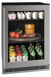
24” Refrigerator
USERGUIDE&SERVICEMANUAL
u-line.com
TableofContents
Intro
Safety
Safety and Warning
Disposal And Recycling
Installation
Environmental Requirements
Electrical
Cutout & Product Dimensions
Side by Side Installation
Anti-Tip Bracket
General Installation
Integrated Panel Dimensions
Integrated Panel Installation
Grille Installation
Door Swing
Door Adjust
Interior Adjustments
Maintenance
Cleaning
Cleaning Condenser
Extended Non-Use
Operating Instructions
First Use
Control Operation
Airflow and Product Loading
Service
Troubleshooting
Wire Diagram
Product Liability
Warranty Claims
Parts
Ordering Replacement Parts
R600a Specifications
System Diagnosis Guide
Compressor Specifications
Troubleshooting Extended
Control Operation - Service
Thermistor
Defrost
Remove Fan and Cover
Warranty
USER GUIDE
u-line.com
Introduction
WELCOME TO U-LINE
CongratulationsonyourU-Linepurchase.Yourproductcomesfromacompanywithover�vedecadesofpremiummodularice
making, refrigeration, and wine preservation experience. U-Line creates products focused on functionality, style, and inspired
innovations — paying close attention to even the smallest details. Applications include residential, outdoor, ADA height
compliant, marine, and commercial. Complete product categories include Beverage Centers, Wine Refrigerators, Ice Machines,
Refrigerators, Freezers, and Dispensers.
Ouradvancedrefrigerationsystems,largeandexiblecapacities,andBuilt-IntoStandOut
®
clean integrated look allow you
topreservetherightproduct,intherightplace,attherighttemperature.Since2014,U-LinehasbeenpartoftheMiddleby
familyofbrands.Allproductsaredesigned,engineered,andassembledinMilwaukee,Wisconsin,USA,andselectproducts
areavailableworldwide.
PRODUCT INFORMATION
Lookingforadditionalinformationonyourproduct?UserGuides,SpecSheets,CADDrawings,ComplianceDocumentation,
andProductWarrantyinformationareallavailableforreferenceanddownloadatu-line.com.
PROPERTY DAMAGE / INJURY CONCERNS
In the unlikely event property damage or personal injury is suspected related to a U-Line product, please take the following
steps:
1. U-LineCustomerCaremustbecontactedimmediatelyat+1.414.354.0300.
2. ServiceorrepairsperformedontheunitwithoutpriorwrittenapprovalfromU-Lineisnotpermitted.Iftheunithasbeen
alteredorrepairedinthe�eldwithoutpriorwrittenapprovalfromU-Line,claimswillnotbeeligible.
GENERAL INQUIRIES
U-Line Corporation
8900N.55thStreet
Milwaukee,Wisconsin53223USA
Monday-Friday8:00amto4:30pmCST
T:+1.414.354.0300
Email: sales@u-line.com
u-line.com
CONNECT WITH US
SERVICE & PARTS ASSISTANCE
Monday-Friday8:00amto4:30pmCST
T:+1.414.354.0300
ServiceEmail:onlineservice@u-line.com
Parts Email: [email protected]
Designed,engineeredandassembledinWI,USA
3
USER GUIDE
u-line.com
Safety and Warning
Safety and Warning
NOTICE
Please read all instructions before installing,
operating, or servicing the appliance.
Use this appliance for its intended purpose only and follow
these general precautions with those listed throughout this
guide:
SAFETY ALERT DEFINITIONS
Throughout this guide are safety items labeled with a
Danger, Warning, or Caution based on the risk type:
Danger means that failure to follow this safety
statement will result in severe personal injury or
death.
Warning means that failure to follow this safety
statement could result in serious personal injury
or death.
Caution means that failure to follow this safety
statement may result in minor or moderate
personal injury, property, or equipment damage.
This unit contains R600a (Isobutane) which is a
ammablehydrocarbon.Itissafeforregular
use. Do not use sharp objects to expedite
defrosting. Do not service without consulting the
“R600aspeci�cations”sectionincludedinthe
User Guide. Do not damage the refrigerant
circuit.
Service must be done by factory authorized
service personnel. Any parts shall be replaced
with like components. Failure to comply could
increase the risk of possible ignition due to
incorrect parts or improper service.
CALIFORNIA PROPOSITION 65
This product contains chemicals known to the
state of California to cause cancer and birth
defects or other reproductive harm.
www.P65warnings.CA.gov
This equipment is to be installed with adequate
backowprotectiontocomplywithapplicable
federal, state and local codes.
DANGER
!
DANGER
!
WARNING
!
CAUTION
!
CAUTION
!
WARNING
!
4
USER GUIDE
u-line.com
Disposal and Recycling
Disposal and Recycling
RISK OF CHILD ENTRAPMENT. Before you throw
awayyouroldrefrigeratororfreezer,takeo�
the doors and leave shelves in place so children
may not easily climb inside.
If the unit is being removed from service for disposal,
check and obey all federal, state, and local regulations
regarding the disposal and recycling of refrigeration
appliances, and follow these steps completely:
1. Remove all consumable contents from the unit.
2. Unplug the electrical cord from its socket.
3. Remove the door(s)/drawer(s).
DANGER
!
5
USERGUIDE
EnvironmentalRequirements
u-line.com
EnvironmentalRequirements
Thismodelisintendedforindoor/interiorapplicationsonly
andisnottobeusedininstallationsthatareopen/
exposedtonaturalelements.
Thisunitisdesignedtooperatebetween50°F(10°C)and
100°F(38°C).Higherambienttemperaturesmayreduce
theunit’sabilitytoreachlowtemperaturesand/orreduce
iceproductiononapplicablemodels.
Forbestperformance,keeptheunitoutofdirectsunlight
andawayfromheatgeneratingequipment.
Inclimateswherehighhumidityanddewpointsare
present,condensationmayappearonoutsidesurfaces.
Thisisconsiderednormal.Thecondensationwill
evaporatewhenthehumiditydrops.
CAUTION
!
Damagescausedbyambienttemperaturesof
40°F(4°C)orbelowarenotcoveredbythe
warranty.
6
USERGUIDE
Electrical
u-line.com
Electrical
WARNING
!
SHOCKHAZARD—ElectricalGrounding
Required.Neverattempttorepairorperform
maintenanceontheunituntiltheelectricityhas
beendisconnected.
Neverremovetheroundgroundingprongfrom
theplugandneveruseatwo-pronggrounding
adapter.
Altering,cuttingorremovingpowercord,
removingpowerplug,ordirectwiringcancause
seriousinjury,fire,lossofpropertyand/orlife,
andwillvoidthewarranty.
Neveruseanextensioncordtoconnectpowerto
theunit.
Alwayskeepyourworkingareadry.
NOTICE
Electricalinstallationmustobserveallstateand
localcodes.Thisunitrequiresconnectiontoa
grounded(three-prong),polarizedreceptacle
thathasbeenplacedbyaqualifiedelectrician.
Theunitrequiresagroundedandpolarized115VAC,
60 Hz,15Apowersupply(normalhouseholdcurrent).An
individual,properlygroundedbranchcircuitorcircuit
breakerisrecommended.AGFCI(groundfaultcircuit
interrupter)isusuallynotrequiredforfixedlocation
appliancesandisnotrecommendedforyourunitbecause
itcouldbepronetonuisancetripping.However,besure
toconsultyourlocalcodes.
SeeCUTOUT&PRODUCTDIMENSIONSforrecommended
receptaclelocation.
7
USER GUIDE
u-line.com
Cutout & Product Dimensions
17 ⁄”
(445 mm)
24 ⁄”
(616 mm)
22 ⁄”
(582 mm)
24 ⁄”
(629 mm)
4 ⁄“ (111 mm)
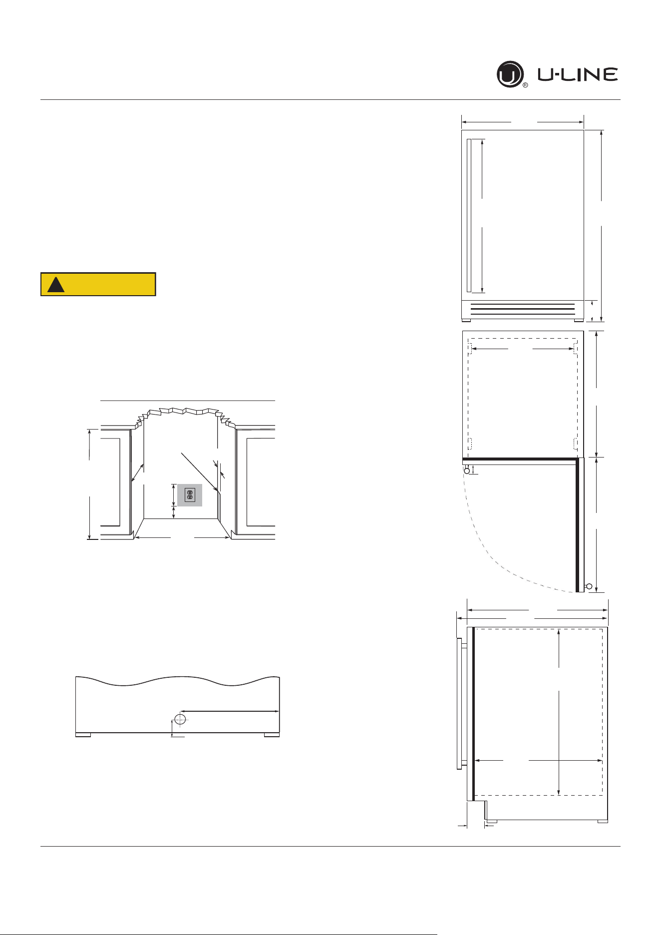
Cutout & Product Dimensions
PREPARE SITE
Your U-Line product has been designed for either free-
standing or built-in installation. When built-in, your unit
does not require additional air space for top, sides, or
rear. However, the front grille must NOT be obstructed,
and clearance is required for an electrical connection in
the rear.
CAUTION
!
Unit can NOT be installed behind a closed cabinet
door.
CUTOUT DIMENSIONS
PRODUCT DIMENSIONS
REAR
FRONT
TOP
SIDE
4"
(102 mm)
7"
(178 mm)
33-7/8"
(860 mm)
to
34-7/8"
(886 mm)
23-3/4"
(605 mm)
Preferred location
for electrical outlet
is in adjacent
cabinet.
24"
(610 mm)
5/8"
(16 mm)
Power Cord
6 ft (183 cm)
1 ⁄”
(35 mm)
11 ¾”
(298 mm)
23
⁄”
(600 mm)
3 ½”
(89 mm)
33 ⁄6”
to
34 ⁄6”
(855 mm
to
881 mm)
28”
(711 mm)
1 ⁄”
(48 mm)
18 ⁄”
(481 mm)
26 ⁄”
(664 mm)
21 ⁄”
(535 mm)
*
*
*Add 1⁄2” for integrated models with 3⁄4” panel installed.
8
USERGUIDE
Side-by-SideInstallation
u-line.com
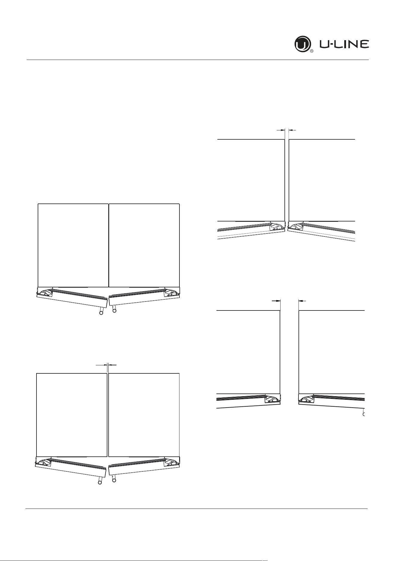
Side-by-SideInstallation
OTHERSITEREQUIREMENTS
Side-by-SideInstallation
Unitsmustoperatefromseparate,properlygrounded
electricalreceptaclesplacedaccordingtoeachunit’s
electricalspecificationsrequirements.
Cutoutwidthforaside-by-sideinstallationisthetotalof
thewidthslistedunderCutoutDimensionsineachunit’s
InstallationGuide.Eachdoorcanbeopenedindividually
(oneatatime)withoutinterference.
However,toensureunobstructeddoorswing(opening
bothdoorsatthesametime),1/4"(6.4mm)ofspace
needstobemaintainedbetweentheunits.
Hinge-by-HingeInstallation(Mullion)
Wheninstallingtwounitshinge-by-hinge,13/16"(22 mm)
isrequiredforintegratedmodels.Additionalspacemaybe
neededforanyknobs,pullsorhandlesinstalled.
Stainlesssteelmodelswhichincludethestandardstainless
handlewillrequire4-9/16"(116mm)toallowbothdoors
toopento90°atthesametime.
1/4" (6 mm)
13/16" (22 mm)
4-9/16" (116 mm)
9
USER GUIDE
u-line.com
Anti-Tip Bracket
Anti-Tip Bracket
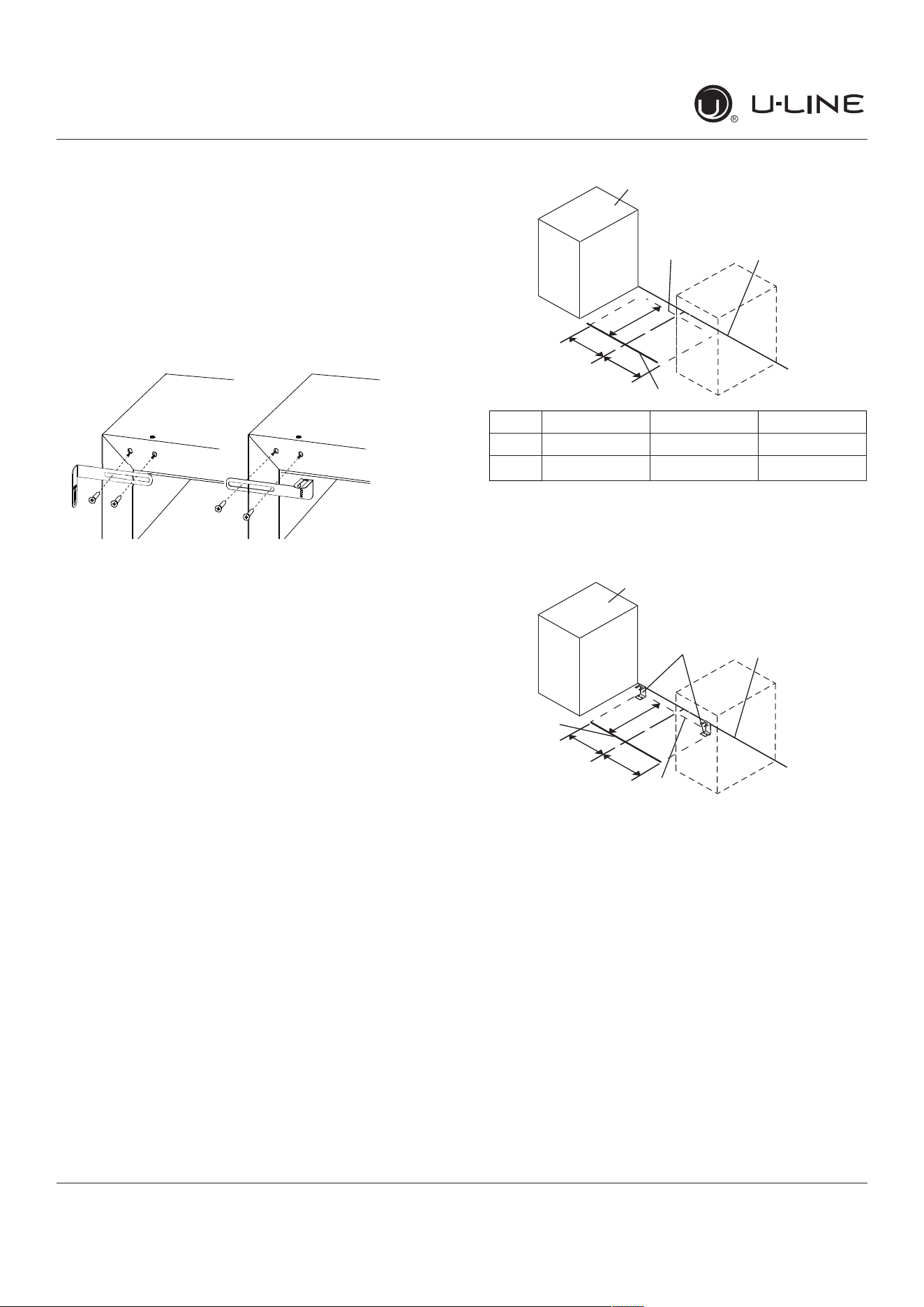
Use one of the methods below to secure the unit
CABINET/COUNTER ANTI-TIP INSTALLATION
(For built-in applications)
1. Slide unit out so screws on front of unit are easily
accessible.
2. Remove the two screws from the front of the unit.
3. Bend bracket along one of the perforations to allow
attachment to the desired adjoining surface.
4. Gently push unit into position. Be careful not to
entangle the electrical cord or water line, if applicable.
5. Check to be sure the unit is level from front to back
and side to side. Make any necessary adjustments.
The unit’s top surface should be approximately 1⁄8”
(3 mm) below the countertop.
6. Secure bracket to adjoining surface.
FLOOR MOUNTED ANTI-TIP INSTALLATION
(For free-standing applications)
1. Locate two anti-tip brackets included with the kit.
2. Place the unit into the area where it will be installed.
Checkthedoor,sides,andtopforaproper�t.Also
test to make sure the door opens and closes freely.
3. Removegrilleandplaceamarkontheooratthe
frontoftheunit.Alsoplaceamarkontheoorinthe
center of the unit.
4. Remove the unit. Using a square, extend center line
“B” (see chart below). This line serves as the back
edge for the anti-tip brackets. From the center line,
measure“A”totheleftandright.Thislineistheouter
edge of each bracket.
C
L
Back wall
Back of unit
Front of unit
Surrounding
area (Top view)
A
A
B
515 518 524
A 7 5⁄8” 9” 11 15⁄6”
B 22” 22” 22”
5. Placetheanti-tipbracketsontheooragainsttheline
drawn for the outer edge. Mark spots for the screw
holes.
C
L
Surrounding
area (Top view)
Drill holes and
mount anti-tip
brackets to floor
Back wall
Front
of
unit
Back
of
unit
A
A
B
6. Use a 1/8” drill to make two starter holes and fasten
theanti-tipbracketstotheoorusingthescrews
provided.
7. Place the unit back into position, making sure the
feet engage the anti-tip brackets properly. Check
thealignmentofthelinesmadeontheoorinstep
3 with the position of the front feet to ensure proper
positioning.
10
USER GUIDE
u-line.com
General Installation
General Installation
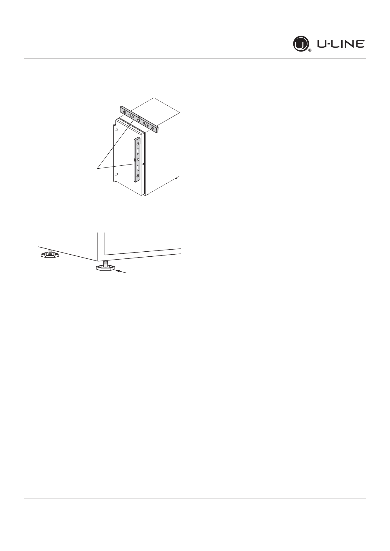
LEVELING INFORMATION
1. Use a level to
con�rmtheunitis
level.Levelshould
beplacedalongtop
edgeandsideedge
asshown.
2. Iftheunitisnotlevel,adjustthelegsonthecornersof
theunitasnecessary.
3. Con�rmtheunitislevelaftereachadjustmentand
repeatthepreviousstepsasneeded.
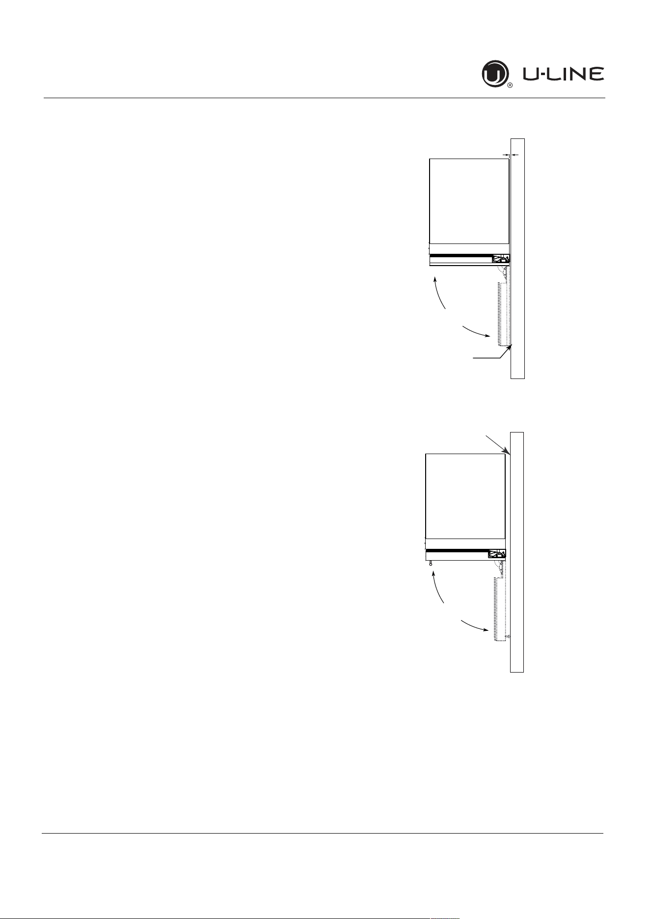
INSTALLATION TIP
Iftheroomoorishigherthantheoorinthecutout
opening,adjusttherearlegstoachieveatotalunitrear
heightof
1⁄8
”(3mm)lessthanopening’srearheight.
Shortentheunitheightinthefrontbyadjustingthefront
legs.Thisallowstheunittobegentlytippedintothe
opening.Readjustthefrontlegstoleveltheunitafteritis
correctlypositionedintheopening.
INSTALLATION
1. Pluginthepower/electricalcord.
2. Gentlypushtheunitintoposition.Becarefulnot
toentanglethecordorwateranddrainlines,if
applicable.
3. Re-checktheleveling,fromfronttobackandsideto
side.Makeanynecessaryadjustments.Theunit’stop
surfaceshouldbeapproximately
1⁄8
”(3mm)below
thecountertop.
4. Installtheanti-tipbracket.
5. Removeinteriorpackingmaterialandwipeoutthe
insideoftheunitwithaclean,water-dampenedcloth.
1
Turn to Adjust
11
USERGUIDE
IntegratedPanelDimensions
u-line.com
IntegratedPanelDimensions
Metricmeasurementsroundedandoptimized.
INTEGRATEDPANEL
NOTICE
Duetodifferencesinsurroundingcabinetrythe
panelmaynotperfectlyalignwithdoor.The
procedurebelowisdesignedtoprovidea
finishedintegratedpanelthatseamlessly
integrateswithsurroundingcabinetry.
PanelPreparation
Afullintegrateddoorpanelcompletelycoversthedoor
frameandprovidesabuilt-inappearance.
NOTICE
Thedoorpanelmustnotweighmorethan20 lbs
(10 kg).
Itisimportanttoensurethatalldrilledholesare
drilledtothecorrectdepthinordertoavoid
splitsinthewoodwhenhardwareisinstalled.
1. Cutthepanelstothedimensionslistedinthe
appropriatediagrambelow.
2. Optional:Stainorfinishpaneltodesiredstainorcolor.
Besuretocloselyfollowtheinstructionsprovidedby
themanufacturer.
3. Optional:Installhandlesandhardware.
NOTICE
Whenapplyinganintegratedpaneltoaunit,
ensurethatbothsidesarefinishedinorderto
preventwarping.Insomeoverlaypanel/frame
installations,thepanelmaybevisiblethrough
theglasswhilethedoorisopen.
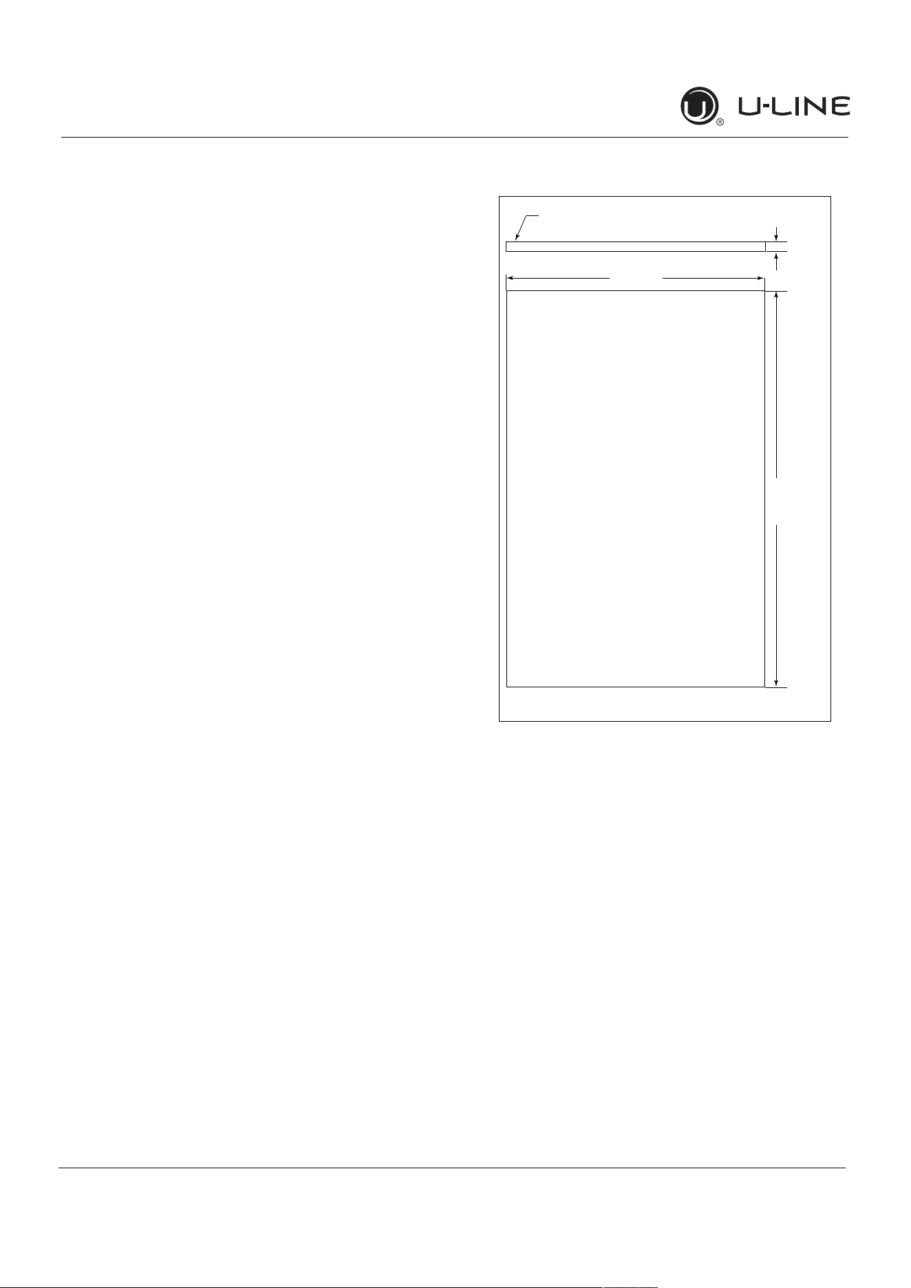
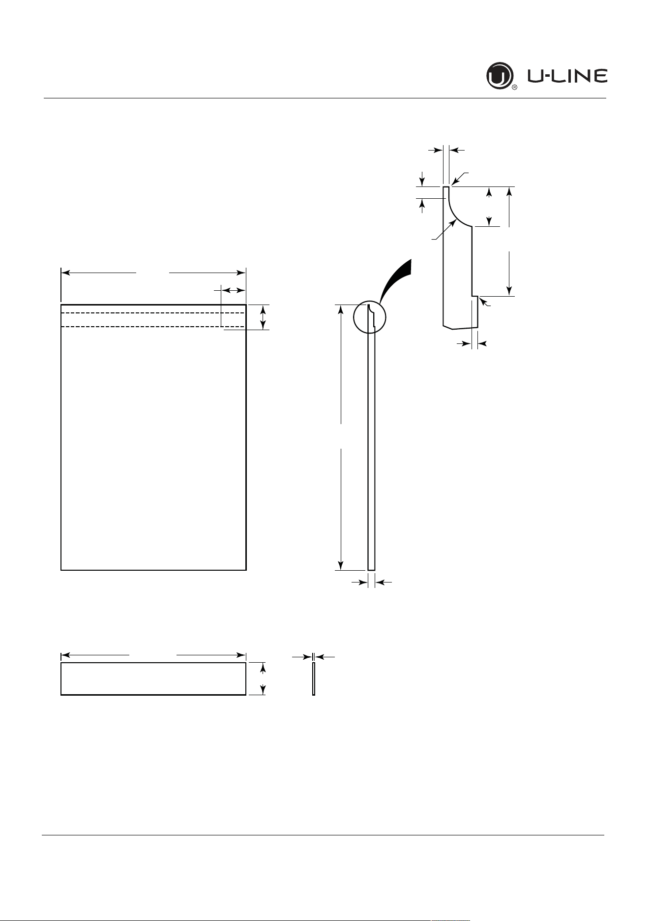
IntegratedPanelDimensions
BACK SURFACE MUST HAVE AMPLE FLAT SURFACE
TO MOUNT OVERLAY PANEL FLAT AND WITHOUT
INTERFERENCE
23-1/2"
(595 mm)
3/4"
(20 mm)
Integrated Panel
30"
(762 mm)
12
USERGUIDE
IntegratedPanelDimensions
u-line.com
HANDLELESSINTEGRATEDDOORPANEL
Thefollowingprocedureisdesignedtoprovideafinished,
handlelesssolidpanelfora24"(600 mm)doorthat
seamlesslyintegrateswithitssurroundingcabinetry.
NOTE:Manycabinetmanufacturersprovideaready
solutionforahandleless,integrateddesignthatcanbe
easilyappliedtoyourmodel.Consultyourcabinet
manufacturerforapplicabledesignandinstallationdetails.
Thecabinetmanufacturer’ssolutiontothisdesignand
integrationdetailwilloftenresultinanintegratedpanel
solutionwhereinthesizeofthepanelmayresultina
heightdimensiontallerthanwhatwespecify.Thiscanbe
achievedprovidedtheadditionalheightispositioned
abovetheappliancedoor.
NOTICE
Theintegratedpanelalignswiththesurrounding
cabinetryand,duetodifferencesincabinetry,
maynotalignperfectlywiththedoor.
Theappliancewillneedupto34-1/2"(876 mm)
totheundersideofthecountertoleaveroomfor
levelingadjustments.
Asinglepreparedoverlaywithinsertmustnot
weighmorethan20lbs(10 kg).
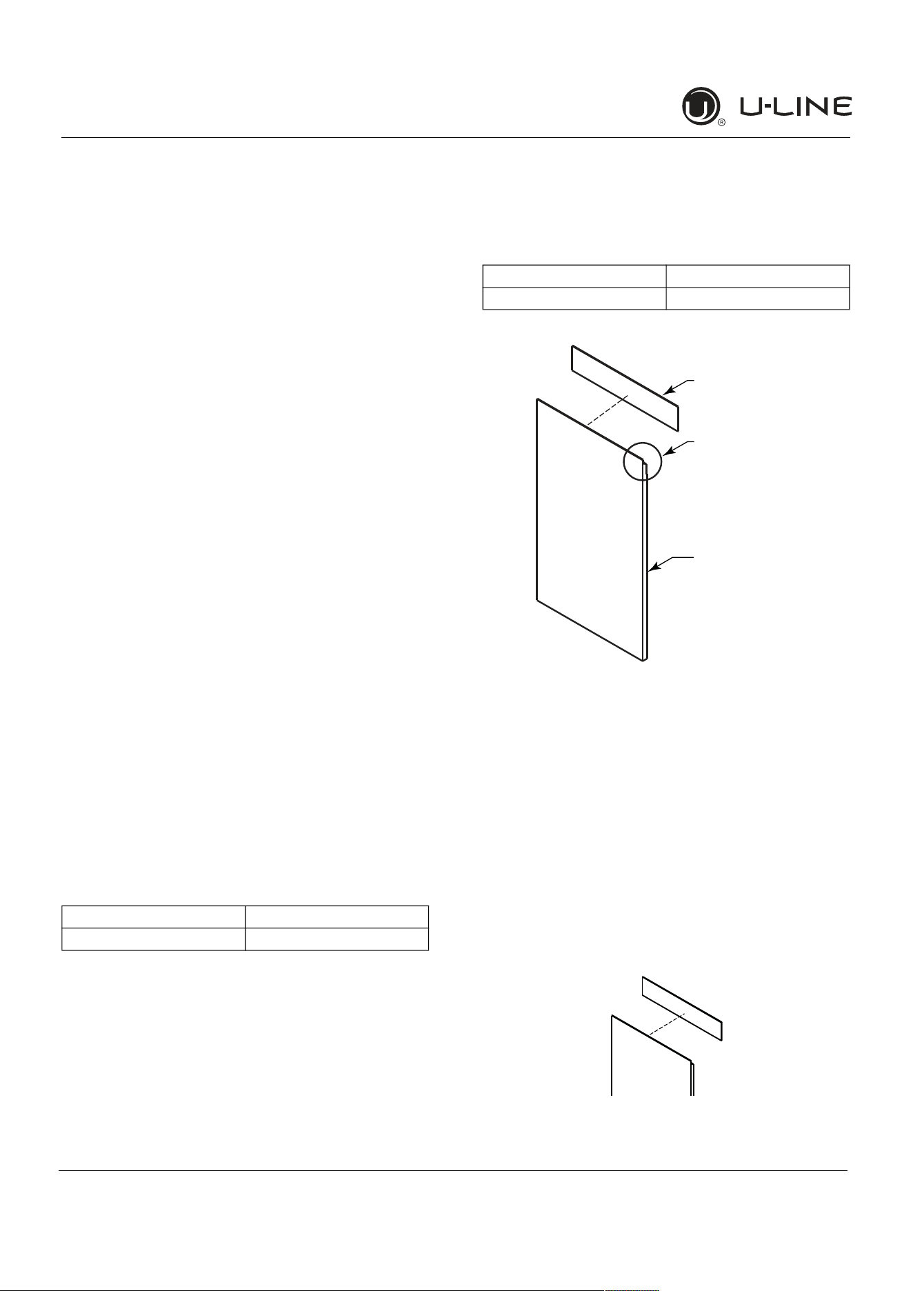
IntegratedPanelPreparation
1. Cutthemainpaneltotheappropriatedimensions
below.Fordetails,seethedrawingsonthenextpage.
2. Createthetopdesignforthehandlelessfeatureand
the1/8"(3 mm)notchfortheinsert(s)indicatedon
theTopDetaildrawing.
3. Preparetheinsert(s)thatwillbackupthehandleless
design.WoodenInsert–Cut1/8"(3 mm)thick
woodeninsert(s)tothedimensionsbelow.
4. Optional:Stainorfinishpanelandwoodeninsertto
desiredstainorcolor.Besuretocloselyfollowthe
instructionsprovidedbythemanufacturer.
NOTICE
Iffinishingpanelorwoodeninsert,allsides
mustbefinishedtopreventwarping.
5. Attachtheinserttothepanel.Woodglueorequivalent
adhesiveshouldbeusedtoattachinserttopanel.
Mainpanelwidth Mainpanelheight
23-1/2"(595 mm) 28-13/16"(732 mm)
Woodeninsertwidth Woodeninsertheight
23-1/2"(595 mm) 3-1/2"(89 mm)
Top Design
and Insert Notch
Wooden Insert
Main Panel
Integrated Panel
AttachWoodenInsert
13
USERGUIDE
IntegratedPanelDimensions
u-line.com
HandlelessIntegratedPanelDimensions
3/4" (20 mm)
28-13/16"
(732 mm)
2-3/4"
(70 mm)
2-3/4"
(70 mm)
R 5/8"
(R16 mm)
1/8"
(3 mm)
1/4" (6 mm)
Wooden Insert
Notch Depth: 1/8" (3 mm)
2-3/8"
(60 mm)
7/8" (22 mm)
Ref.
Top Detail
Insert Notch
Top Design
1/8" (3 mm)
3-1/2" (89 mm)
23-1/2"
(595 mm)
Wooden Insert Dimensions
23-1/2"
(595 mm)
14
USERGUIDE
IntegratedPanelDimensions
u-line.com
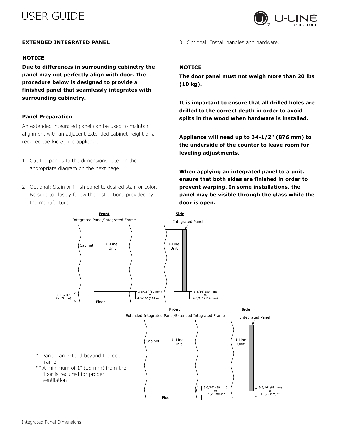
EXTENDEDINTEGRATEDPANEL
NOTICE
Duetodifferencesinsurroundingcabinetrythe
panelmaynotperfectlyalignwithdoor.The
procedurebelowisdesignedtoprovidea
finishedpanelthatseamlesslyintegrateswith
surroundingcabinetry.
PanelPreparation
Anextendedintegratedpanelcanbeusedtomaintain
alignmentwithanadjacentextendedcabinetheightora
reducedtoe-kick/grilleapplication.
1. Cutthepanelstothedimensionslistedinthe
appropriatediagramonthenextpage.
2. Optional:Stainorfinishpaneltodesiredstainorcolor.
Besuretocloselyfollowtheinstructionsprovidedby
themanufacturer.
3. Optional:Installhandlesandhardware.
NOTICE
Thedoorpanelmustnotweighmorethan20 lbs
(10 kg).
Itisimportanttoensurethatalldrilledholesare
drilledtothecorrectdepthinordertoavoid
splitsinthewoodwhenhardwareisinstalled.
Appliancewillneedupto34-1/2"(876 mm)to
theundersideofthecountertoleaveroomfor
levelingadjustments.
Whenapplyinganintegratedpaneltoaunit,
ensurethatbothsidesarefinishedinorderto
preventwarping.Insomeinstallations,the
panelmaybevisiblethroughtheglasswhilethe
doorisopen.
3-5/16" (89 mm)
to
4-5/16" (114 mm)
U-Line
Unit
U-Line
Unit
Integrated Panel
Integrated Panel/Integrated Frame
Front
Side
Front Side
3-5/16" (89 mm)
to
4-5/16" (114 mm)
Floor
Cabinet
> 3-5/16"
(> 89 mm)
3-5/16" (89 mm)
to
1" (25 mm)**
U-Line
Unit
Extended Integrated Panel/Extended Integrated Frame
Floor
Cabinet
3-5/16" (89 mm)
to
1" (25 mm)**
*
U-Line
Unit
Integrated Panel
* Panelcanextendbeyondthedoor
frame.
** Aminimumof1"(25mm)fromthe
floorisrequiredforproper
ventilation.
15
USERGUIDE
IntegratedPanelDimensions
u-line.com
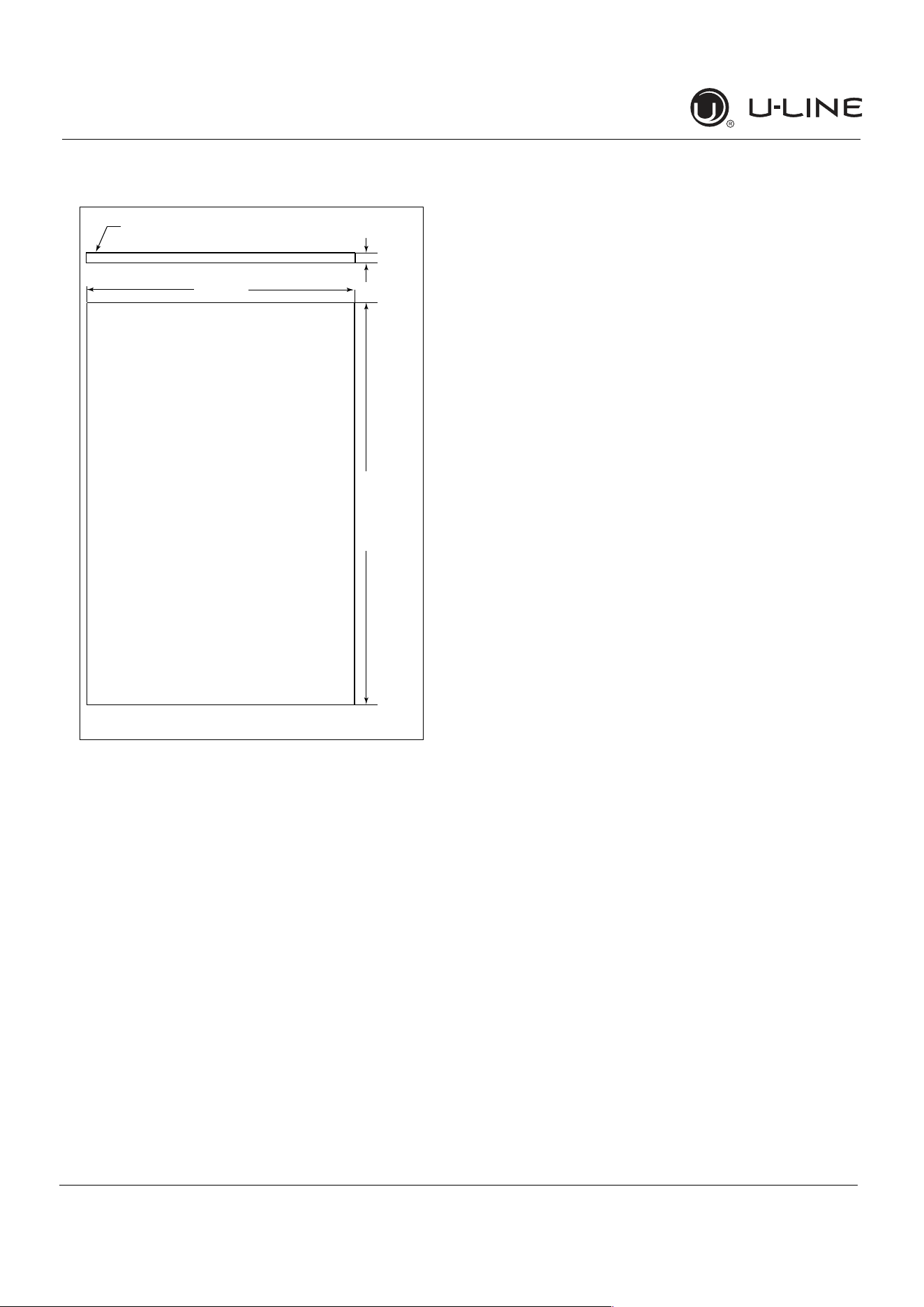
ExtendedIntegratedPanelDimensions
BACK SURFACE MUST HAVE AMPLE FLAT SURFACE
TO MOUNT OVERLAY PANEL FLAT AND WITHOUT
INTERFERENCE
23-1/2"
(595 mm)
3/4"
(20 mm)
Integrated Panel
32-7/8" -
33-7/8"
(834 mm -
860 mm)*
* Aminimumof1"(25mm)isrequiredfromthe
floortothebottomoftheextendedintegrated
panel/frameforproperventilation.
IntegratedGrille
Ifyouwouldliketocoverthegrillewithanintegrated
panel,purchaseU-Line’sadjustablegrilleaccessories.
24”-SalesAccessory:ULAGRILLE24
Completeinstructions,includingdimensionsoftheinte
-
gratedgrillepanel,areincludedwiththeaccessory.
16
USERGUIDE
IntegratedPanelInstallation
u-line.com
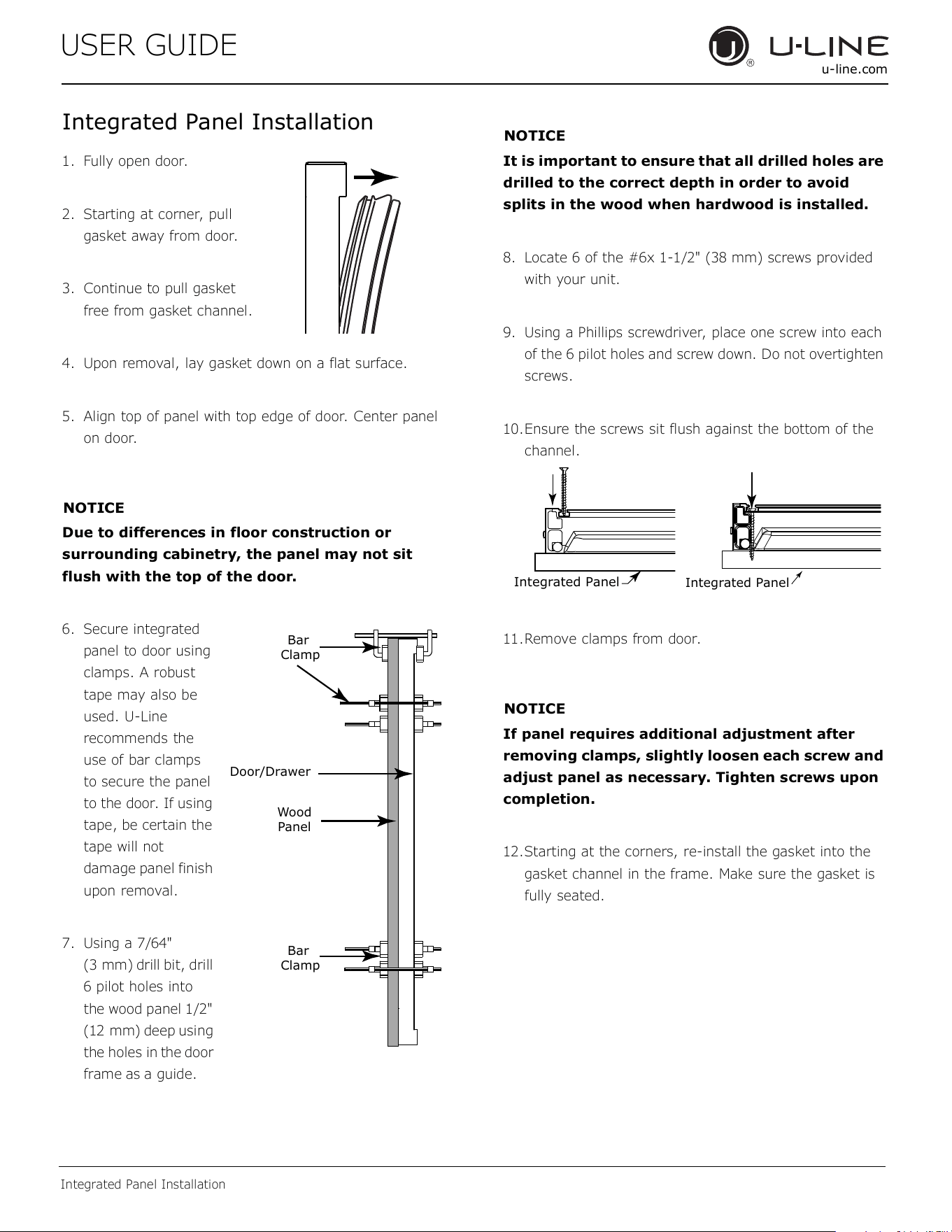
IntegratedPanelInstallation
1. Fullyopendoor.
2. Startingatcorner,pull
gasketawayfromdoor.
3. Continuetopullgasket
freefromgasketchannel.
4. Uponremoval,laygasketdownonaflatsurface.
5. Aligntopofpanelwithtopedgeofdoor.Centerpanel
ondoor.
NOTICE
Duetodifferencesinfloorconstructionor
surroundingcabinetry,thepanelmaynotsit
flushwiththetopofthedoor.
6. Secureintegrated
paneltodoorusing
clamps.Arobust
tapemayalsobe
used.U-Line
recommendsthe
useofbarclamps
tosecurethepanel
tothedoor.Ifusing
tape,becertainthe
tapewillnot
damagepanelfinish
uponremoval.
7. Usinga7/64"
(3 mm)drillbit,drill
6pilotholesinto
thewoodpanel1/2"
(12 mm)deepusing
theholesin
the
door
frame
as
aguide.
NOTICE
Itisimportanttoensurethatalldrilledholesare
drilledtothecorrectdepthinordertoavoid
splitsinthewoodwhenhardwoodisinstalled.
8. Locate6ofthe#6x1-1/2"(38 mm)screwsprovided
withyourunit.
9. UsingaPhillipsscrewdriver,placeonescrewintoeach
ofthe6pilotholesandscrewdown.Donotovertighten
screws.
10.Ensurethescrewssitflushagainstthebottomofthe
channel.
11.Removeclampsfromdoor.
NOTICE
Ifpanelrequiresadditionaladjustmentafter
removingclamps,slightlylooseneachscrewand
adjustpanelasnecessary.Tightenscrewsupon
completion.
12.Startingatthecorners,re-installthegasketintothe
gasketchannelintheframe.Makesurethegasketis
fullyseated.
Wood
Panel
Door/Drawer
Bar
Clamp
Bar
Clamp
Integrated Panel
Integrated Panel
17
USERGUIDE
GrilleInstallation
u-line.com
GrilleInstallation
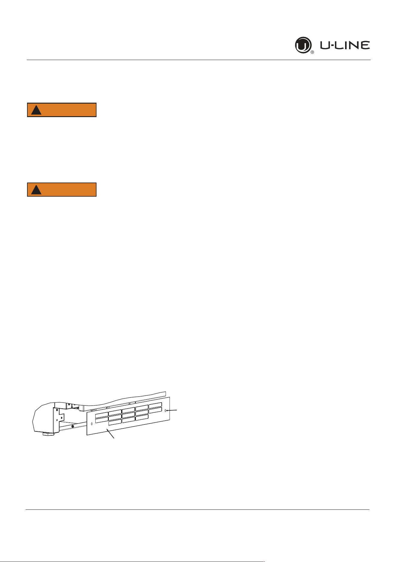
REMOVINGANDINSTALLINGGRILLE
WARNING
!
Disconnectelectricpowertotheunitbefore
removingthegrille.
Whenusingtheunit,thegrillemustbeinstalled.
WARNING
!
DONOTtouchthecondenserfins.Thecondenser
finsareSHARPandcanbeeasilydamaged.
Removingthegrille
1. Disconnectpowertotheunit.
2. Loosenthetwoscrews(1).
3. Removegrille(2)fromunit.
Installingthegrille
1. Aligncabinetandgrilleholesandsecure,butdonot
overtightengrillescrews(1).
2. Reconnectpowertotheunit.
1
2
18
USERGUIDE
DoorSwing
u-line.com
DoorSwing
ForIntegratedmodelsthatareinstalledadjacenttoawall,
1/2"(13 mm)clearanceisrecommendedfromwallon
hingesidetoallowthedoortoopen90°.Allowfor
additionalspaceforanyknobsorpullsinstalledonthe
integratedpanel/frame.
StainlessSteelmodelsthatareinstalledadjacenttoawall
require2
-
1/4"(57 mm)doorclearanceonhingesideto
allowfordoorhandle.
Unitshaveazeroclearancewheninstalledadjacentto
cabinets.
Wall
Wall
90°
Door Swing
90°
Door Swing
Space Required
For any Knobs or Pulls
2-1/4" MIN
(57 mm MIN)
Integrated
Stainless
1/2" (13 mm)
19
USER GUIDE
u-line.com
Door Adjustments
Door Adjustments
DOOR ALIGNMENT AND ADJUSTMENT
Align and adjust the door if it is not level or not sealing
properly. If the door is not sealed, the unit may not cool
properly, or excessive frost or condensation may form in
the interior.
NOTICE
Properly aligned, the door’s gasket should be
�rmlyincontactwiththecabinetalltheway
aroundthedoor(nogaps).Carefullyexaminethe
door’sgaskettoensurethatitis�rmlyincontact
withthecabinet.Alsomakesurethedoorgasket
isnotpinchedonthehingesideofthedoor.
Donotattempttousethedoortoraiseorpivot
yourunit.Thiswouldputexcessivestressonthe
hingesystem.
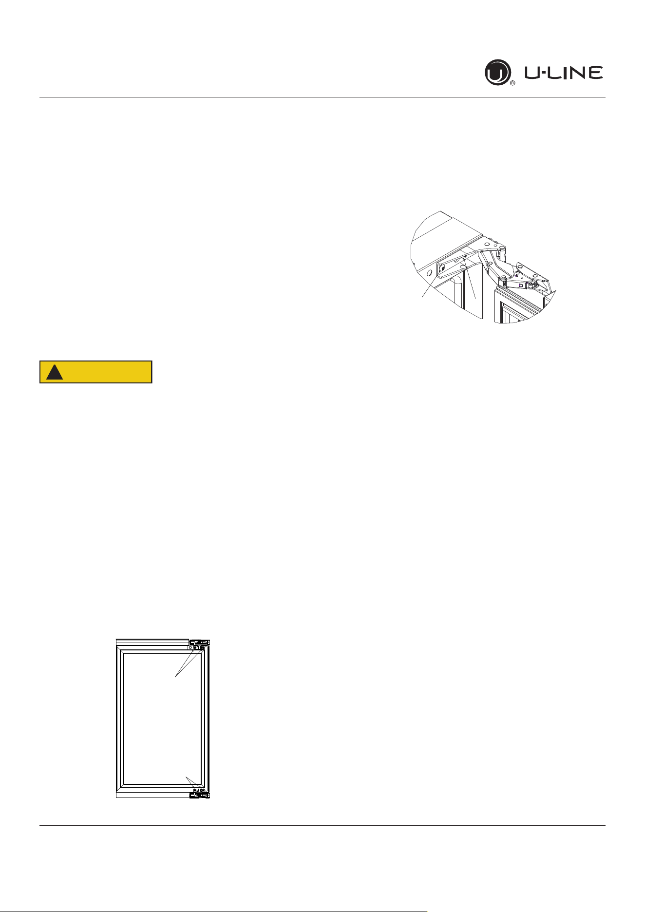
AlignmentandAdjustmentProcedure
1. Open door and remove gasket near the hinges.
2. Using a T-25 Torx bit, loosen each pair of Torx head
screws both the upper and lower hinge plates.
3. Square and align door as necessary.
4. Tighten Torx head screws on hinge.
5. Reinstall gasket into the channel starting at the corner.
REVERSING THE DOOR
1. Open door.
2. Using T-25 Torx bit loosen screw #1 and remove screw
#2 on top and bottom hinge. Slide and remove the
door from the unit.
Note:Onehingeincludesametalspacer.Spacer
mustbeusedwiththathingewhenreversingthe
door.
3. Remove caps from screw heads on opposite side (2 on
top and 2 on bottom). Using #2 Phillips bit, remove
the 4 underlying screws. Reinstall the screws and caps
on the opposite side.
4. Partially install screw #1 in the outer most holes on
top and bottom. Rotate door 180o, align hinge over
screw #1 and slide/seat into position. Reinstall screw
#2 on top and bottom. Tighten both screws and install
hinge cover.
Alignandadjustthedoor:
Align and adjust the door (see DOOR ALIGNMENT AND
ADJUSTMENT).
T-25 Torx Screw
T-25 Torx Screw
2
1
CAUTION
!
20
USER GUIDE
u-line.com
First Use
Temperaturedisplayedre�ectsactual
temperature inside unit.
Initial startup requires no adjustments. When plugged
in, the unit will begin operating under the factory default
settings.Iftheunitwasturnedo�duringinstallation,
simply press and the unit will immediately switch on. To
turntheunito�,press.
Ifthetemperaturedisplayedisdi�erentthanselected,the
unit is progressing towards the selected temperature. Time
to reach set point varies based upon ambient temperature,
temperature of product loaded, door openings, etc. U-Line
recommends allowing the unit to reach set points before
loading.
NOTICE
First Use
21
USER GUIDE
u-line.com
Control Operation
Control Operation
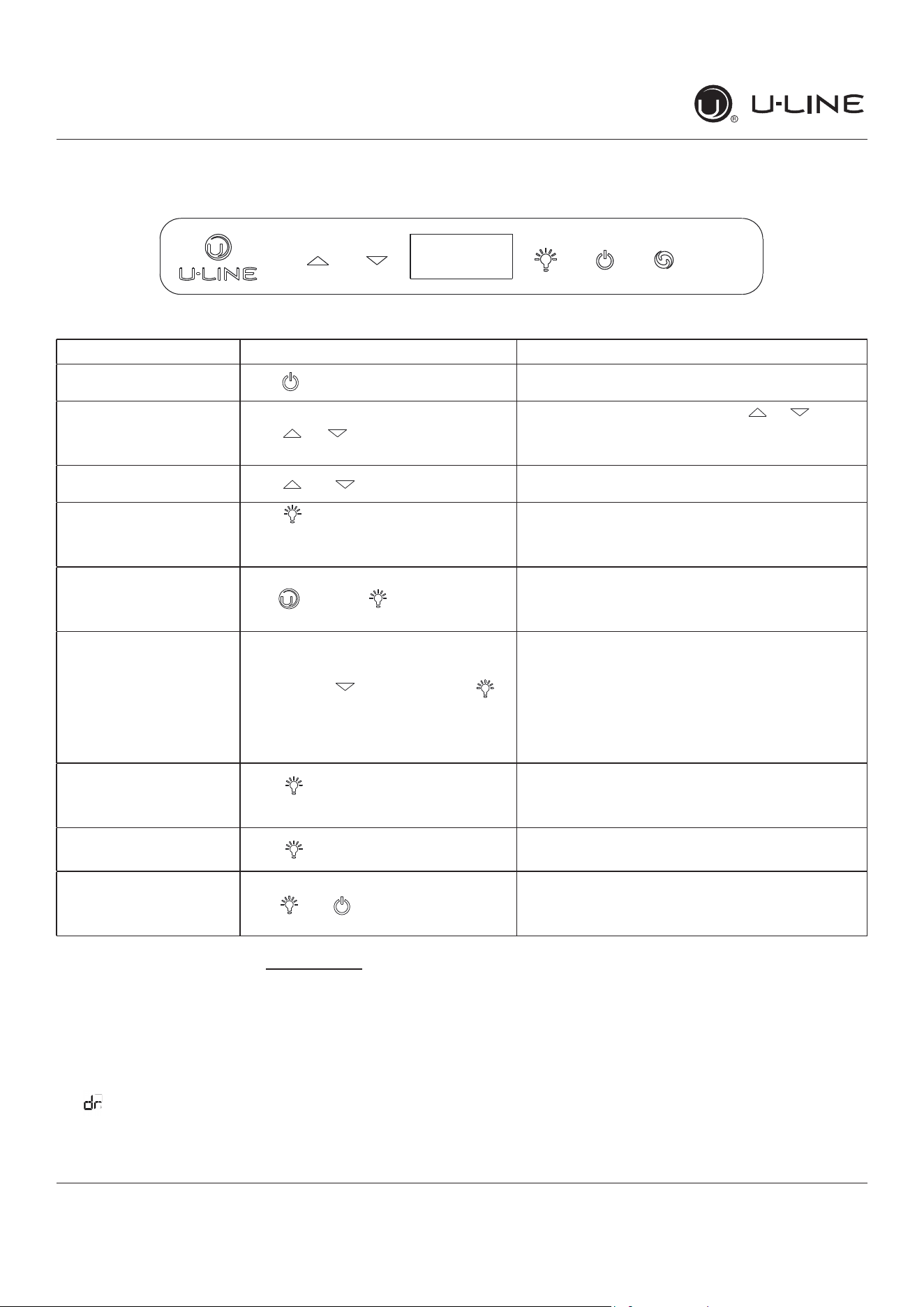
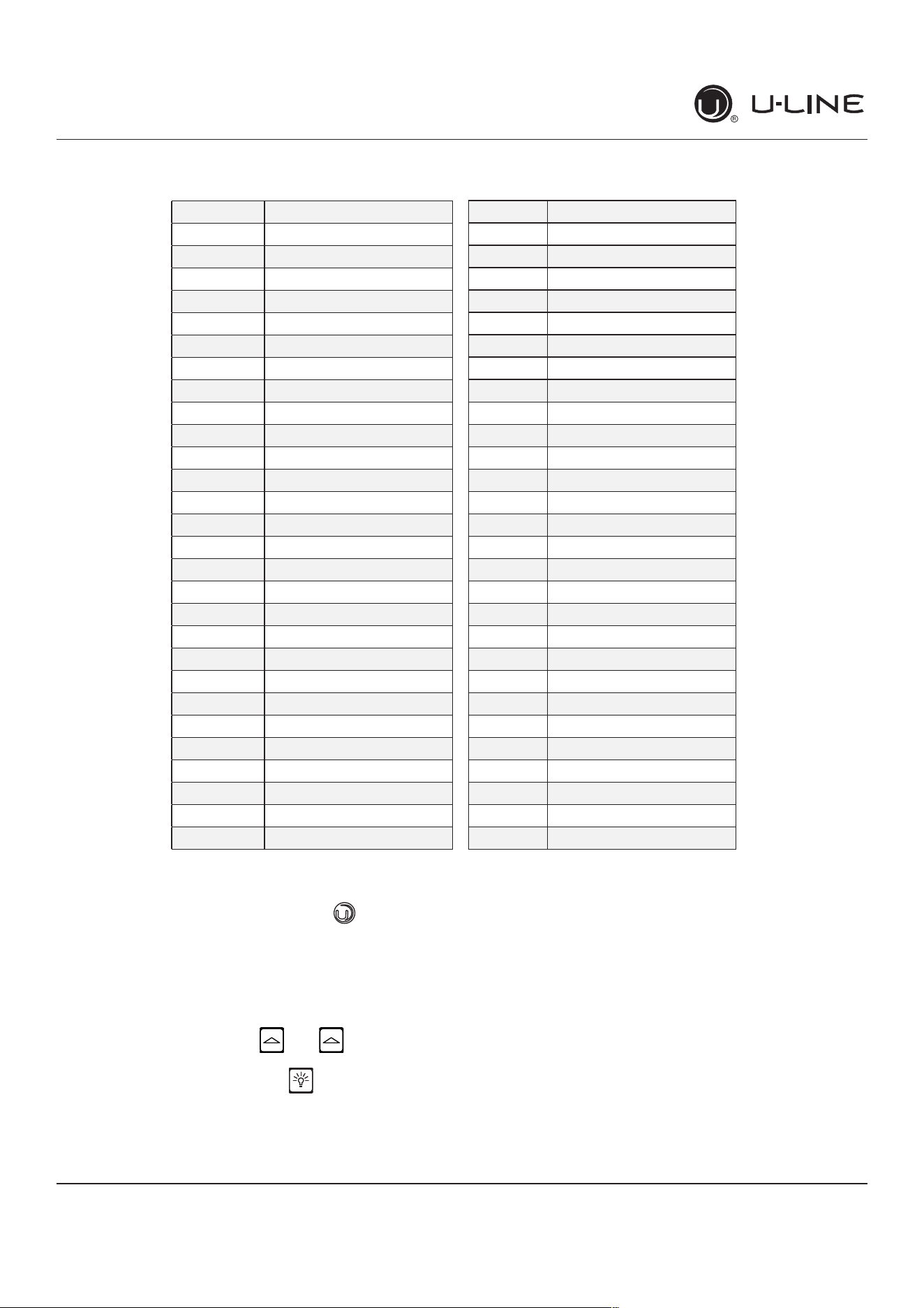
CONTROL FUNCTION GUIDE
FUNCTION COMMAND NOTES
ON/OFF Press and release Unit will immediately turn On or OFF
Adjust Temperature Press or and release
Whenthedisplayisashing,pressorto
adjust the set point temperature. Note: temperature
displayed is the actual temperature inside unit
Togglebetween
º
F /
º
C Hold and for 5 seconds Thedisplaywillchangeunits
Leaveinteriorlighton
Press and release to leave interior
lightonfor12hours;pressagainto
deactivate
After12hours,factorydefaultisrestored;lightwill
turn on when door is open
Hide Display Hold and press
Displaywillturno�whendoorisclosed.Unitwill
continue to operate. Repeat command to turn on
display
Adjustlightcolor
Whileholdingpressandrelease
toscrollthroughlightingoptions
Option Open Door Closed Door
00
White White
0 1
Blue Blue
02
White Blue
Lightwillbesetatfullintensitywhendoorisopen,
and 50% intensity when door is closed.
EnableSabbathMode
Press and hold for 5 seconds and
release
The
o
F /
o
Csymbolwillashbrieyafter5seconds.
Interiorlightanddisplaywillgodarkandremainso
until user resets mode - unit continues to operate
DisableSabbathMode Press and release Displayandinteriorlightreturntonormaloperation
ShowroomMode Hold and for 5 seconds
The
º
F /
º
Csymbolwillash.Displaywillbelitand
interiorlightwillfunction.Unitwillnotcool.Repeat
command to return to normal operation
ThisunitisStar-Kcertied.Seewww.star-k.org for more details.
DOOR ALERT NOTIFICATION
When the door is left open for more than 5 minutes:
• A tone will sound for several seconds every minute
•
will appear in display
• Closed door to silence alert and reset
22
USER GUIDE
u-line.com
Airow&ProductLoading
Restrictingair�owmayresultinpoorproduct
performance,productfailure,anduneveninternal
temperaturesandmayfreezecontents.
• Do not block the front grille - no additional clearance
around sides, top or rear of unit is needed for ventilation
• Do not install behind a closed door
• When loading, leave space between internal fans, vents,
and side walls to allow air to circulate freely
NOTICE
AIRFLOW
External
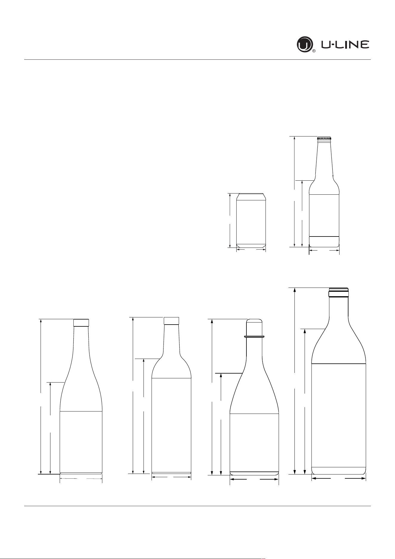
PRODUCT LOADING
Bottles and cans come in many shapes and sizes. Not
allbottlesandcanswill�toneveryshelfandwinerack.
LargerdiameterchampagneandMagnumbottlesonly�t
onwinerackswhennotedontheproductspeci�cations.
When determining capacities U-Line uses typical 12 oz.
cans, 12 oz. bottles, 750 mL white wine and red wine
bottles shown below.
Air�owandProductLoading
Typical Can
(12 oz)
4
(123 mm)
(66 mm)
2
7⁄3”
9⁄3”
Typical Bottle
(12 oz)
9”
5
2
7⁄6”
5⁄6”
(135 mm)
(64mm)
(229 mm)
Typical White
Wine Bottle
11
(298 mm)
(750 mL)
3
¾”
(184 mm)
(82 mm)
11
¼”
¼”
Typical Red
Wine Bottle
11
(302 mm)
8
3”
29⁄3”
¾”
(222 mm)
(750 mL)
(76 mm)
Typical
Champagne Bottle
(750 mL)
3
⁄6”
7
¾”
⁄6”
(299 mm)
(94 mm)
(195 mm)
11
Magnum Bottle
(1.5 L)
13
10
3
1⁄8”
(334 mm)
11⁄32”
(263 mm)
7⁄32”
(98 mm)
Internal
23
USER GUIDE
u-line.com
Interior Adjustments
Interior Adjustments
All 5 Class models feature side mounted rack supports with
19 adjustment positions.
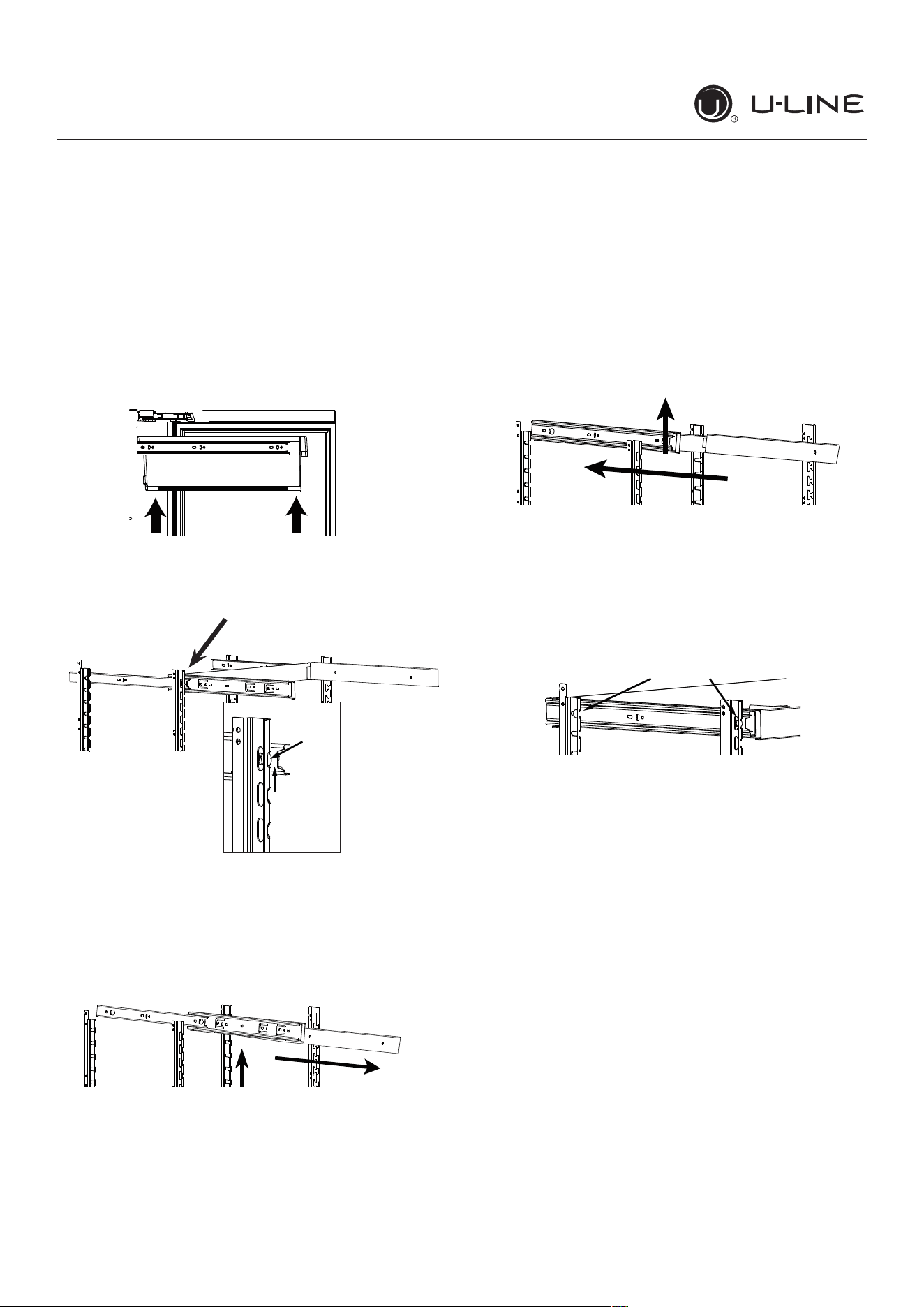
All refrigerators ship with 3 Slide and Secure storage bins.
Remove and reposition as desired.
Slide and Secure Storage Bin Removal
1. Empty and remove bin.
2. Firmly grasp both sides of storage bin frame and lift
frontendslightly(about1/4”)tocenterthepininthe
slot.
3. Pull frame towards you until all pins are clear of the
slots. If only repositioning the frame, do not remove
completely-goto“StorageBinInstallation”Step2.
4. Slightly tilt one side. Gently pull frame towards you to
remove from unit.
Note: Take care when removing frame to avoid
scratching interior of unit.
5. Once removed, retract the slides.
Note: The slides on the frame have a thin coating
which is used to block moisture and provide
lubrication. Use care when handling.
Slide and Secure Storage Bin Installation
1. Insert empty storage bin frame into unit with one side
tilted slightly downward until back pin is between front
and rear rail supports.
2. Tilt frame back to horizontal and line up 2 back pins
with rear rail support. Line up left side of frame with
rear and front rail support. Continue inserting frame
until both pins engage. The front will set down slightly
and lock into place. Repeat on right side.
3. Fully extend frame, position bin over frame and lower
(rear�rst)intoposition.
Slide and Secure Storage Bins
Glassinsertsaredesignedsobottlesandcanssitat.The
inserts may be removed when storing produce or other
items.Theridgesinthebottomfacilitateairow.
Clean the storage bins with soap and water.
Center
the pin
Center
the pins
Front Pin
Back Pin
24
USERGUIDE
Cleaning
u-line.com
Cleaning
StainlessModels
Stainlessdoorpanelsandhandlescandiscolorwhen
exposedtochlorinegas,poolchemicals,saltwateror
cleanerswithbleach.
Keepyourstainlessunitlookingnewbycleaningwitha
goodqualityall-in-onestainlesssteelcleanerandpolish
monthly.ForbestresultsuseClaire
®
StainlessSteel
PolishandCleaner.Comparableproductsareacceptable.
Frequentcleaningwillremovesurfacecontaminationthat
couldleadtorust.Someinstallationsmayrequirecleaning
weekly.
Donotcleanwithsteelwoolpads.
Donotusestainlesssteelcleanersorpolisheson
anyglasssurfaces.
Cleananyglasssurfaceswithanon-chlorineglass
cleaner.
Donotusecleanersnotspecificallyintendedfor
stainlesssteelonstainlesssteelsurfaces(this
includesglass,tileandcountercleaners).
Ifanysurfacediscoloringorrustingappears,cleanit
quicklywithBon-Ami
®
orBarkeepersFriendCleanser
®
andanonabrasivecloth.Alwayscleanwiththegrain.
AlwaysfinishwithClaire
®
StainlessSteelPolishand
Cleanerorcomparableproducttopreventfurther
problems.
UsingabrasivepadssuchasScotchbrite™will
causethegraininginthestainlesssteelto
becomeblurred.
Rustnotcleaneduppromptlycanpenetratethe
surfaceofthestainlesssteelandcomplete
removaloftherustmaynotbepossible.
IntegratedModels
Tocleanintegratedpanels,usehouseholdcleanerperthe
cabinetmanufacturer’srecommendation.
INTERIORCLEANING
Disconnectpowertotheunit.
Cleantheinteriorandallremovedcomponentsusinga
mildnonabrasivedetergentandwarmwatersolution
appliedwithasoftspongeornon-abrasivecloth.
Rinsetheinteriorusingasoftspongeandcleanwater.
Donotuseanysolvent-basedorabrasive
cleaners.Thesetypesofcleanersmaytransfertasteto
theinteriorproductsanddamageordiscolorthelining.
DEFROSTING
Undernormalconditionsthisunitdoesnotrequiremanual
defrosting.Minorfrostontherearwallorvisiblethrough
theevaporatorplateventsisnormalandwillmeltduring
eachoffcycle.
Ifthereisexcessivebuild-upof1/4"(6 mm)ormore,
manuallydefrosttheunit.
Ensurethedoorisclosingandsealingproperly.
Highambienttemperatureandexcessivehumiditycan
alsoproducefrost.
CAUTION
!
DONOTuseanicepickorothersharp
instrumenttohelpspeedupdefrosting.These
instrumentscanpuncturetheinnerliningor
damagethecoolingunit.DONOTuseanytypeof
heatertodefrost.Usingaheatertospeedup
defrostingcancausepersonalinjuryand
damagetotheinnerlining.
25
USERGUIDE
Cleaning
u-line.com
NOTICE
Thedrainpanwasnotdesignedtocapturethe
watercreatedwhenmanuallydefrosting.To
preventwaterfromoverflowingthedrainpan
andpossiblydamagingwatersensitiveflooring,
theunitmustberemovedfromcabinetry.
Todefrost:
1. Disconnectpowertotheunit.
2. Removeallproductsfromtheinterior.
3. Propthedoorinanopenposition(2in.[50mm]
minimum).
4. Allowthefrosttomeltnaturally.
5. Afterthefrostmeltscompletelycleantheinteriorand
allremovedcomponents.(SeeINTERIORCLEANING).
6. Whentheinteriorisdry,reconnectpowerandturnunit
on.
26
USER GUIDE
u-line.com
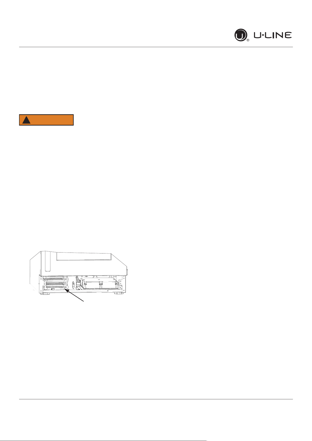
Cleaning Condenser
Cleaning Condenser
INTERVAL - EVERY SIX MONTHS
Tomaintainoperationale�ciency,keepthefrontgrillefree
ofdustandlint,andcleanthecondenserwhennecessary.
Dependingonenvironmentalconditions,moreorless
frequentcleaningmaybenecessary.
WARNING
!
Disconnect electric power to the unit before
cleaning the condenser.
NOTICE
DO NOT use any type of cleaner on the condenser
unit. Condenser may be cleaned using a vacuum,
soft brush, or compressed air.
1. Removethegrille.SeeGRILLEINSTALLATION).
2. Cleanthecondensercoilusingasoftbrushorvacuum
cleaner.
3. Installthegrille.
Condenser
27
USERGUIDE
ExtendedNon-Use
u-line.com
ExtendedNon-Use
VACATION/HOLIDAY,PROLONGEDSHUTDOWN
Thefollowingstepsarerecommendedforperiodsof
extendednon-use:
1. Removeallconsumablecontentfromtheunit.
2. Disconnectthepowercordfromitsoutlet/socketand
leaveitdisconnecteduntiltheunitisreturnedto
service.
3. Ificeisontheevaporator,allowicetothawnaturally.
4. Cleananddrytheinterioroftheunit.Ensureallwater
hasbeenremovedfromtheunit.
5. Thedoormustremainopentopreventformationof
moldandmildew.Opendooraminimumof2"
(50 mm)toprovidethenecessaryventilation.
WINTERIZATION
Iftheunitwillbeexposedtotemperaturesof40°F(5°C)
orless,thestepsabovemustbefollowed.
Forquestionsregardingwinterization,please
callU-Lineat414.354.0300.
CAUTION
!
Damagecausedbyfreezingtemperaturesisnot
coveredbythewarranty.
28
USER GUIDE
u-line.com
Troubleshooting
u-line.com
If you think your U-Line product is malfunctioning, read the
CONTROL OPERATION section to clearly understand the
function of the control.
If the problem persists, read the NORMAL OPERATING
SOUNDS and TROUBLESHOOTING GUIDE sections below
to help you quickly identify common problems and possible
causes and remedies. Most often, this will resolve the
problem without the need to call for service.
If you do not understand a troubleshooting remedy, or your
product needs service, contact U-Line Corporation directly
at +1.800.779.2547.
When you call, you will need your product Model and Serial
Numbers. This information appears on the Model and Serial
number plate located on the upper right or rear wall of the
interior of your product.
All models incorporate rigid foam insulated cabinets to
providehighthermaleciencyandmaximumsound
reduction for its internal working components. Despite this
technology, your model may make sounds that are
unfamiliar.
Normal operating sounds may be more noticeable because
of the unit’s environment. Hard surfaces such as cabinets,
wood,vinylortiledoorsandpaneledwallshavea
tendencytoreectnormalapplianceoperatingnoises.
Listed below are common refrigeration components with a
brief description of the normal operating sounds they
make. NOTE: Your product may not contain all the
components listed.
• Compressor: The compressor makes a hum or pulsing
sound that may be heard when it operates.
BEFORE CALLING FOR SERVICE
TROUBLESHOOTING GUIDE
ELECTROCUTION HAZARD. Never attempt to
repair or perform maintenance on the unit
before disconnecting the main electrical power.
Troubleshooting - What to check when problems occur:
NORMAL OPERATING SOUNDS
IF SERVICE IS REQUIRED
Troubleshooting
• Evaporator:Refrigerantowingthroughanevaporator
may sound like boiling liquid.
• Condenser Fan: Air moving through a condenser may
be heard.
• Automatic Defrost Drain Pan: Water may be heard
dripping or running into the drain pan when the unit is
in the defrost cycle.
DANGER
!
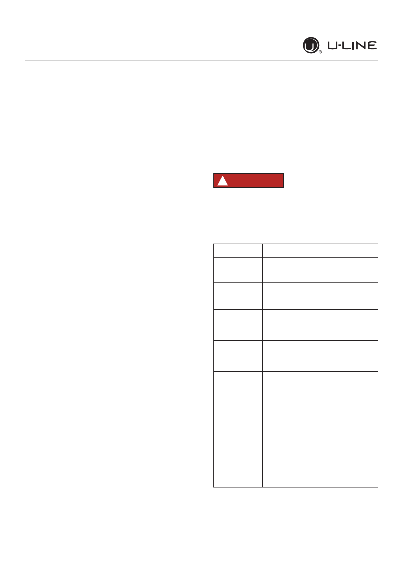
Problem Possible Cause and Remedy
Interior Light
Does Not
Illuminate
If the unit is cooling, it may be in
Sabbath mode.
Light Remains
on When Door
Is Closed.
Turno�lightswitchifequipped.
Adjust light actuator bracket on bottom
of door.
Unit Develops
Frost on
Internal
Surfaces.
Ensure the door is closing and sealing
properly.
Unit Develops
Condensation
onExternal
Surfaces.
Theunitisexposedtoexcessive
humidity. Moisture will dissipate as
humidity levels decrease.
Product is Not
Cold Enough
Air temperature does not indicate
product temperature. See CHECKING
PRODUCT TEMPERATURE below.
Adjust the temperature to a cooler set
point.
Ensureunitisnotlocatedinexcessive
ambient temperatures or in direct
sunlight.
Ensure the door is closing and sealing
properly.
Ensure the interior light has not
remained on too long.
Ensure nothing is blocking the front
grille, found at the bottom of the unit.
Ensure the condenser coil is clean and
free of any dirt or lint build-up.
29
USER GUIDE
u-line.comu-line.com
Troubleshooting
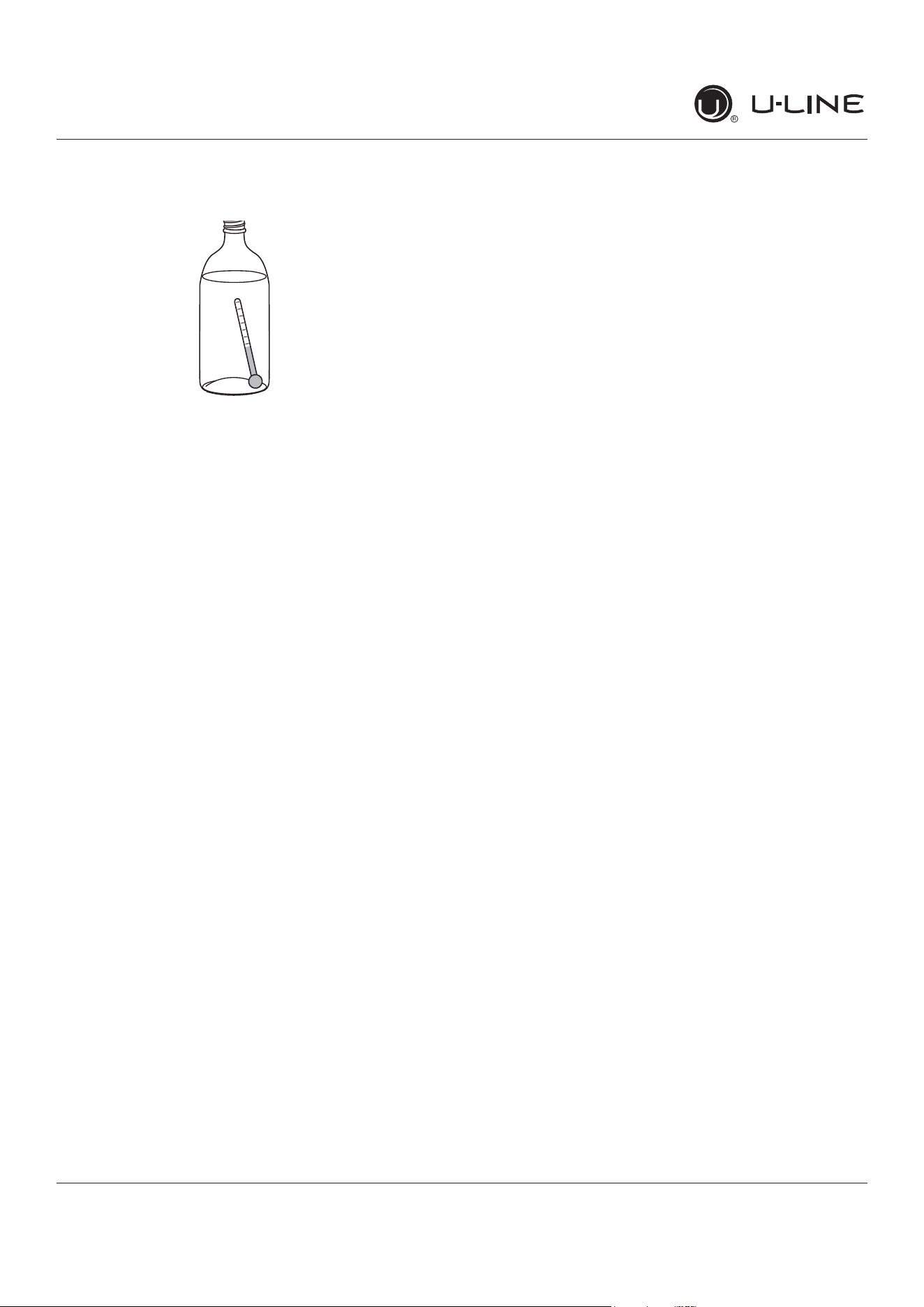
CHECKING PRODUCT TEMPERATURE
To check the actual product temperature in the
unit:
1. Partiallyllaplastic(nonbreakable)bottlewithwater.
2. Insert an accurate thermometer.
3. Tighten the bottle cap securely.
4. Place the bottle in the desired area for 24 hours.
5. Avoid opening the unit during the testing period.
6. After 24 hours, check the temperature of the water.
If required, adjust the temperature control in a small
increment(seeCONTROLOPERATION).
Causeswhicha�ecttheinternaltemperaturesof
the cabinet include:
• Temperature setting.
• Ambient temperature where installed.
• Installation in direct sunlight or near a heat source.
• The number of door openings and the time the door is
open.
• Thetimetheinternallightisilluminated.(Thismainly
a�ectsproductonthetoprackorshelf.)
• Obstruction of front grille or condenser.
30
USER GUIDE
u-line.com
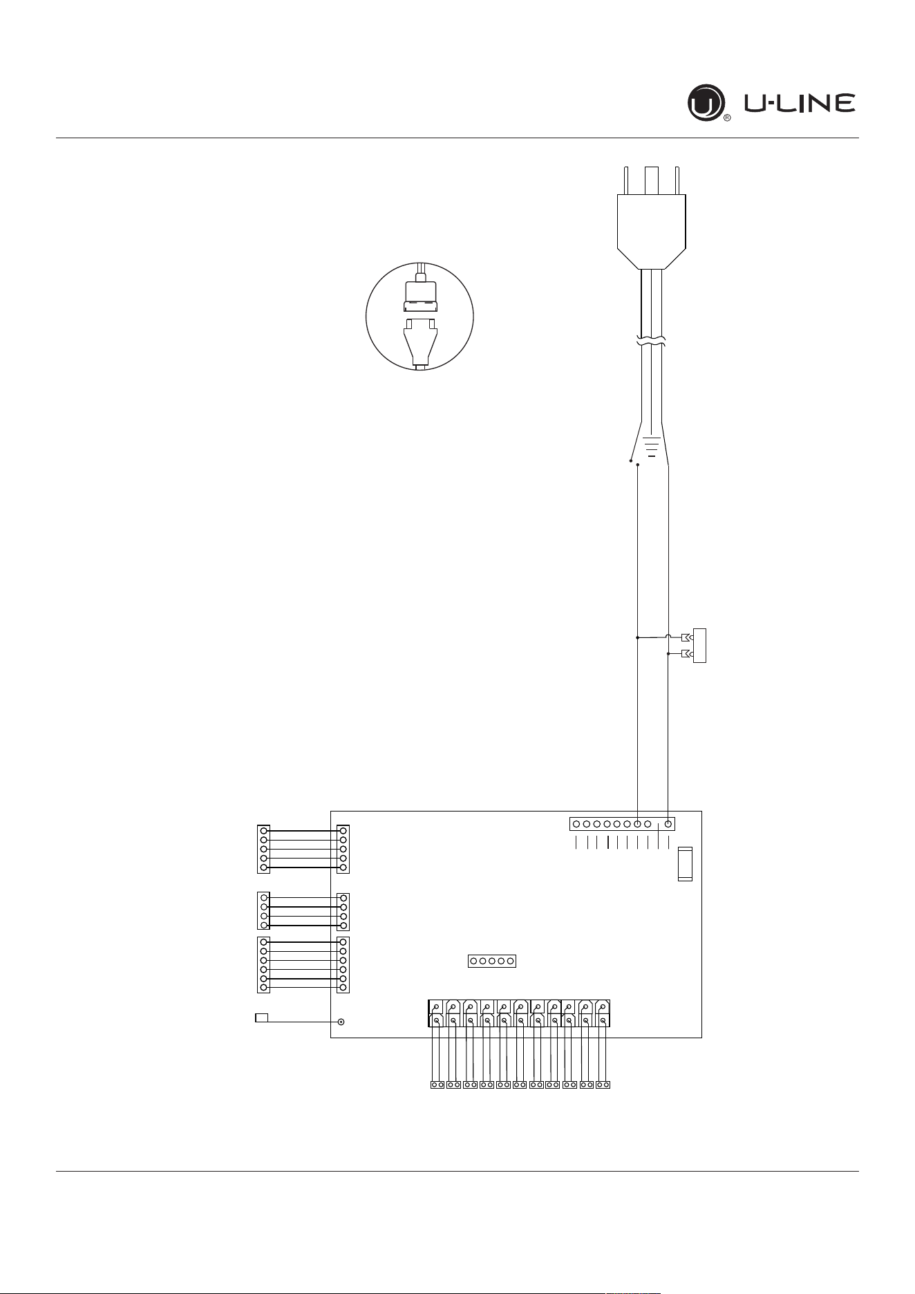
Wire Diagram
Wire Diagram
115 V
Open
Open
Open
Open
Open
Open
Black
N.C.
White
FUSE
11
10
22
1
1
12
White light
Blue light
L/T Evap fan
R/B Evap fan
Condenser fan
L/T Zone temp
L/T Door switch
R/B Door switch
L/T Evap temp
R/B Zone temp
R/B Evap temp
Compressor
Open
Programming
W
I
FI
Ant
e
nna
Di
ag
n
o
s
t
ics
V
C
C
C
o
ntro
l
U
se
r
I
n
te
r
face
42392_A
1 51 6 1 4
(If Applicable)
POWER CORD
ASSEMBLY
220-240 VOLT
PLUG
LIVE
BLACK (115V)
BROWN (220-240V)
NEUTRAL
WHITE (115V)
DARK BLUE (220-240V)
31
USER GUIDE
u-line.com
Product Liability
Product Liability
Field service technicians are authorized to make an initial
assessment in the event of reported damages. If there are
any questions about the process involved, the technician
should call U-Line for further explanation.
While inspecting for defects or installation issues, photos
should be taken to document any damages or issues found.
During the assessment, if the service technician is able to
�ndthesourceofthedamageanditcanberesolvedby
replacement of a part, the servicer is authorized to replace
the part in question. The part that caused the damage
must be returned to U-Line in its entirety. The part must
be clearly labeled with the serial number of the unit it was
removed from, the date, and the servicer who removed the
part.
If the service technician determines the damage is the
result of installation issues (water connection/drain, etc.),
theconsumerwouldbenoti�edandtheissuesshallbe
resolved at the direction of the consumer.
If damage is evident and the service technician is
unableto�ndthesource,U-Linemustbecontactedat
1.800.799.2547 for further direction.
8900 N. 55th Street • Milwaukee, WI 53223
T: +1.414.354.0300 • F: +1.414.354.5696
Website: www.u-line.com
Right product. Right place.
Right temperature Since 1962.
32
USER GUIDE
u-line.com
Warranty Claims
Thefollowinginformationde�nestheparametersfor�linga
warranty claim:
• Validserialnumberneeded
• Validmodelnumberneeded
• Claimsmustbesubmittedonlineat
www.U-LineService.com
• 60daysubmittaldeadlinefromdateofcompleted
service
• Onlyonerepairorunitperwarrantyclaim
• Partordernumberswillberequiredwhensubmitting
forwarrantylabor
Unitsmustberegisteredpriortowarrantysubmittal.
Customersmayregisteratwww.U-Line.com.Aproof
ofpurchaseisrequired.Wealsoacceptthefollowing
informationtoupdatewarranty:
• Newconstructionoccupancydocuments
• Closingpaperwork
• Finalbilling-Remodel
WarrantypartswillbeshippedatnochargeafterU-Line
con�rmswarrantystatus.Pleaseprovidethemodel,serial
number,partnumberandpartdescription.Somepartswill
requirecolororvoltageinformation.
Warranty Claims
17 14862 05 0527
Year
Factory
use Only
Factory
use Only
Month
33
USER GUIDE
u-line.com
Parts
16
13
1
2
21
27
26
18
9
15
23
8
17
12
3
14
4
25
7
11
5
20
6
22
19
10
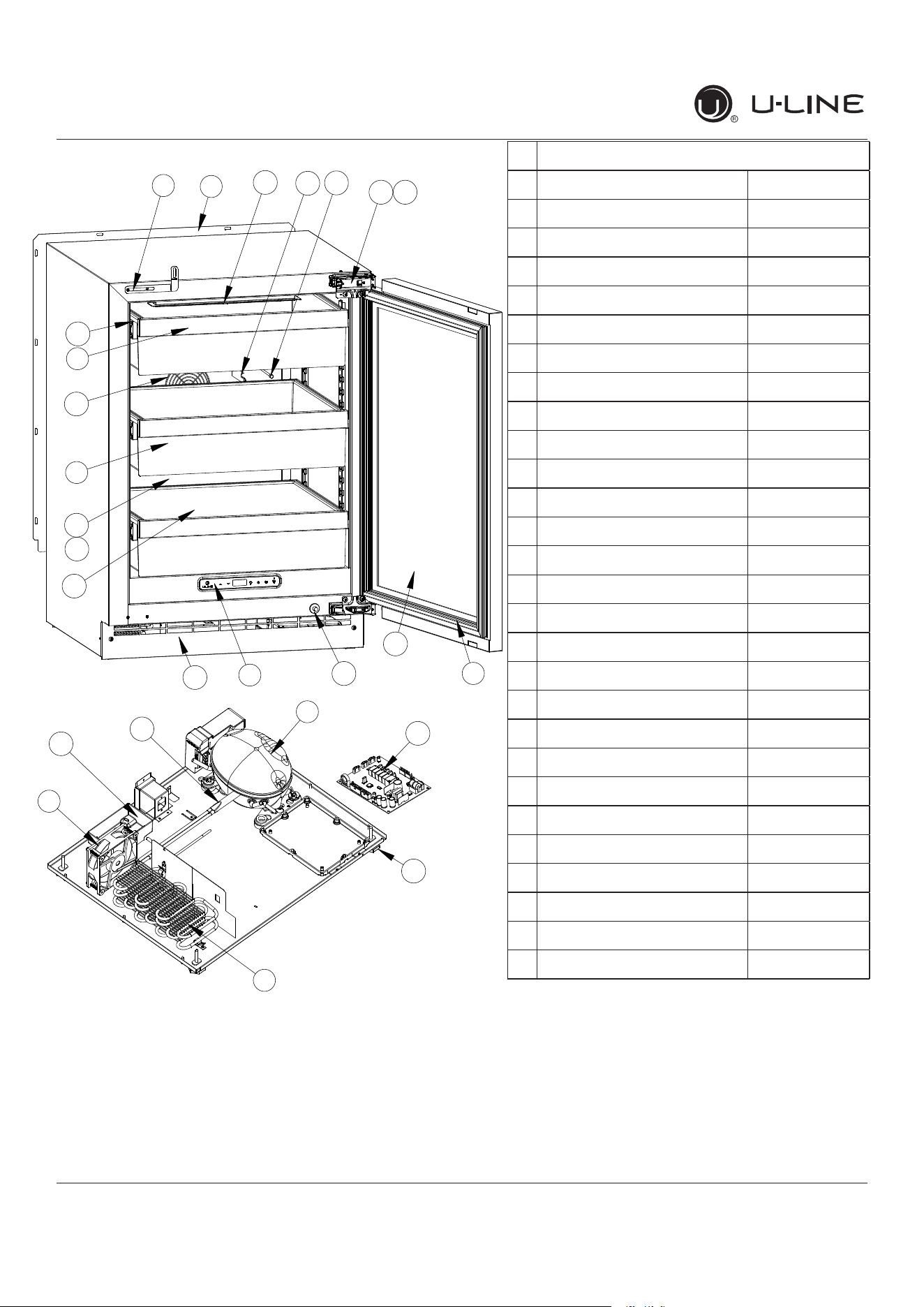
Parts
UHRE524-IS01A
1 ANTI-TIP BRACKET 80-55449-00
2 BACK PANEL 80-55481-00
3 STORAGE BIN 80-54059-00
4 BIN FRONT 80-55482-00
5 COMPRESSOR W/ELECTRICALS 80-55452-00
6 CONDENSER ASSEMBLY 80-55453-00
7 CONDENSER FAN 80-54014-00
8 DISPLAY MODULE 80-55429-00
9 DOOR ASSEMBLY 80-55489-00
10 DRAIN PAN 80-54217-00
11 DRIER 80-54055-00
12 EVAPORATOR ASSEMBLY 80-55486-00
13 EVAPORATOR COVER 80-55485-00
14 EVAPORATOR FAN W/COVER 80-55457-00
15 GASKET, DOOR 80-54039-00
16 GLASS SHELF 80-54058-00
17 GRILLE 80-55487-00
18 HINGE ASSEMBLY 80-55374-00
19 HINGE COVER (2) 80-54001-00
20 LEG LEVELERS (4) 80-54019-00
21 LED LIGHT, 2 COLOR 80-55272-00
22 MAIN BOARD 80-55398-00
23 PLUNGER SWITCH 80-55375-00
24 POWER CORD* 80-55462-00
25 SLIDE ASSEMBLY 80-55509-00
26 THERMISTOR 80-54006-00
27 THERMISTOR COVER 80-55464-00
28 WIRE HARNESS, BOARD* 80-55466-00
*Not Shown
34
USER GUIDE
u-line.com
Ordering Replacement Parts
Parts may be ordered online at www.U-Line.com
See our contact information below:
www.U-LineService.com (with service login)
Phone Number: +1.800.779.2547
NOTICE
Use only genuine U-Line replacement parts.
The use of non-U-Line parts can reduce speed
oficeproduction,causewatertoover�owfrom
ice maker mold, damage the unit, and void the
warranty.
Warranty parts will be shipped at no charge after U-Line
con�rmswarrantystatus.Pleaseprovidethemodel,serial
number,partnumberandpartdescription.Somepartswill
require color or voltage information.
IfU-Linerequiresthereturnoforiginalparts,wewill
inform you when the parts order is taken. This
requirement will be noted on your packing list. A
prepaid shipping label will be emailed to you. Please
enclose a copy of the parts packing list and be sure the
model and serial numbers are legible on the paperwork.
Tag the part with the reported defect.
Customers and non-authorized servicers may order non-
warranty parts at www.u-line.com. Authorized servicers
with a servicer login may order non-warranty parts at
www.u-lineservice.com.
Ordering Replacement Parts
35
USER GUIDE
u-line.com
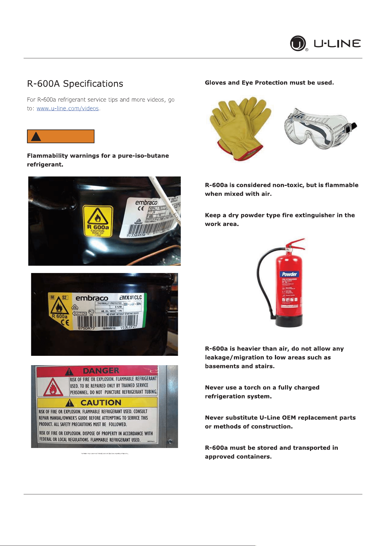
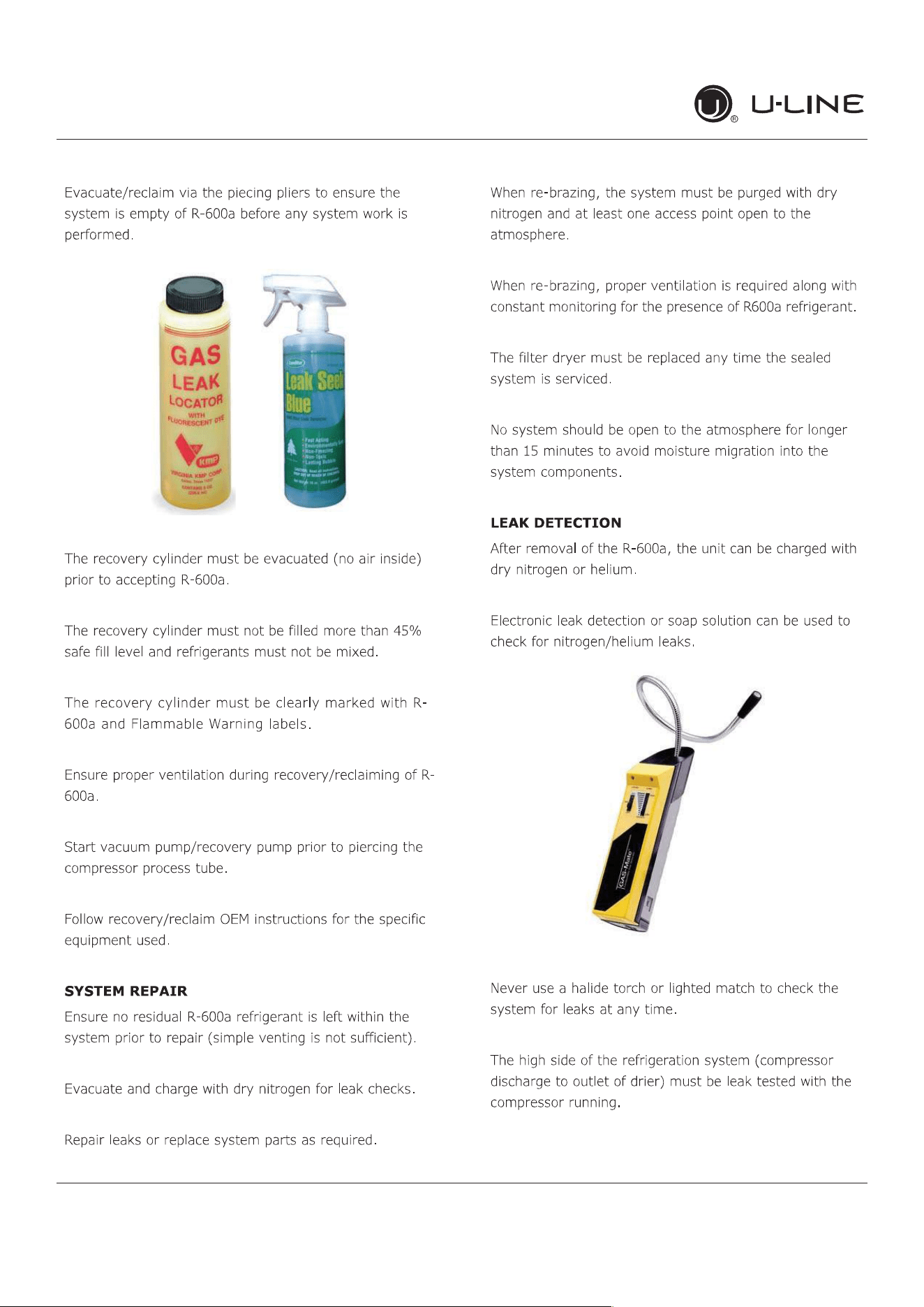
R-600ASpeci�cations
WARNING
!
36
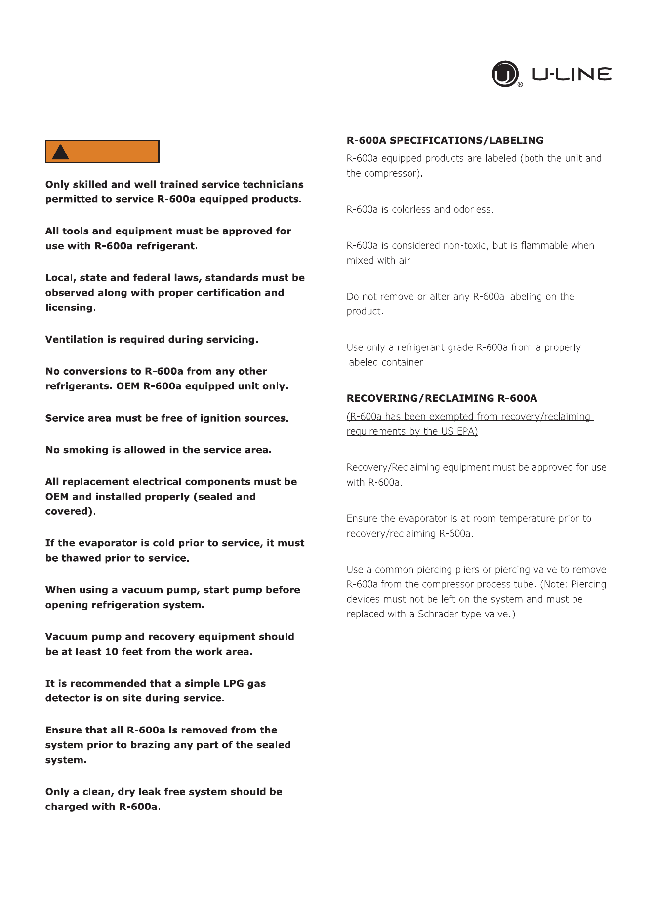
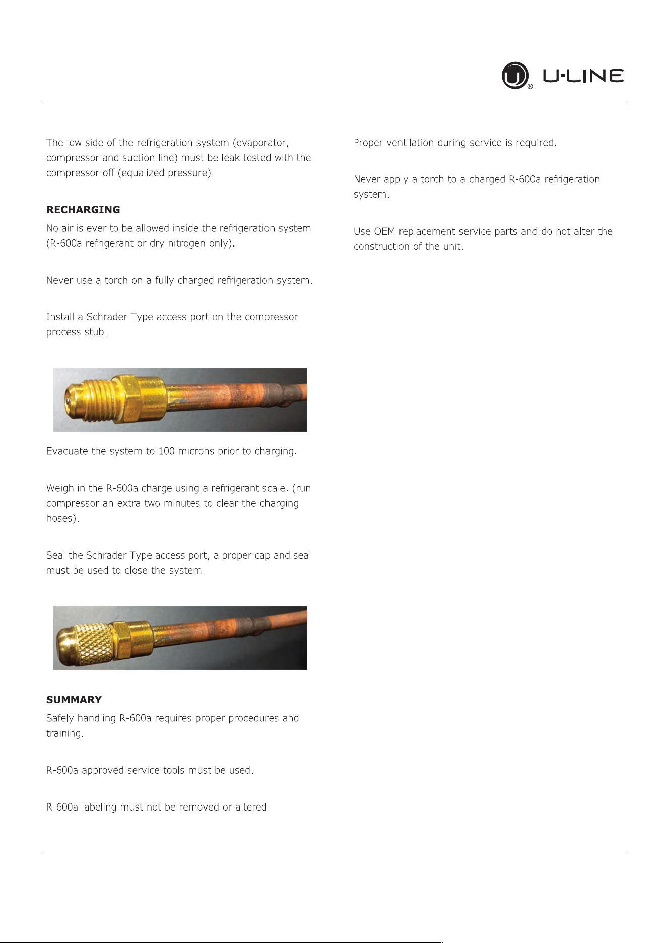
R-600ASpeci�cations
USER GUIDE
u-line.com
WARNING
!
37
USER GUIDE
u-line.com
R-600ASpeci�cations
38
R-600ASpeci�cations
USER GUIDE
u-line.com
39
USER GUIDE
u-line.com
System Diagnosis Guide
System Diagnosis Guide
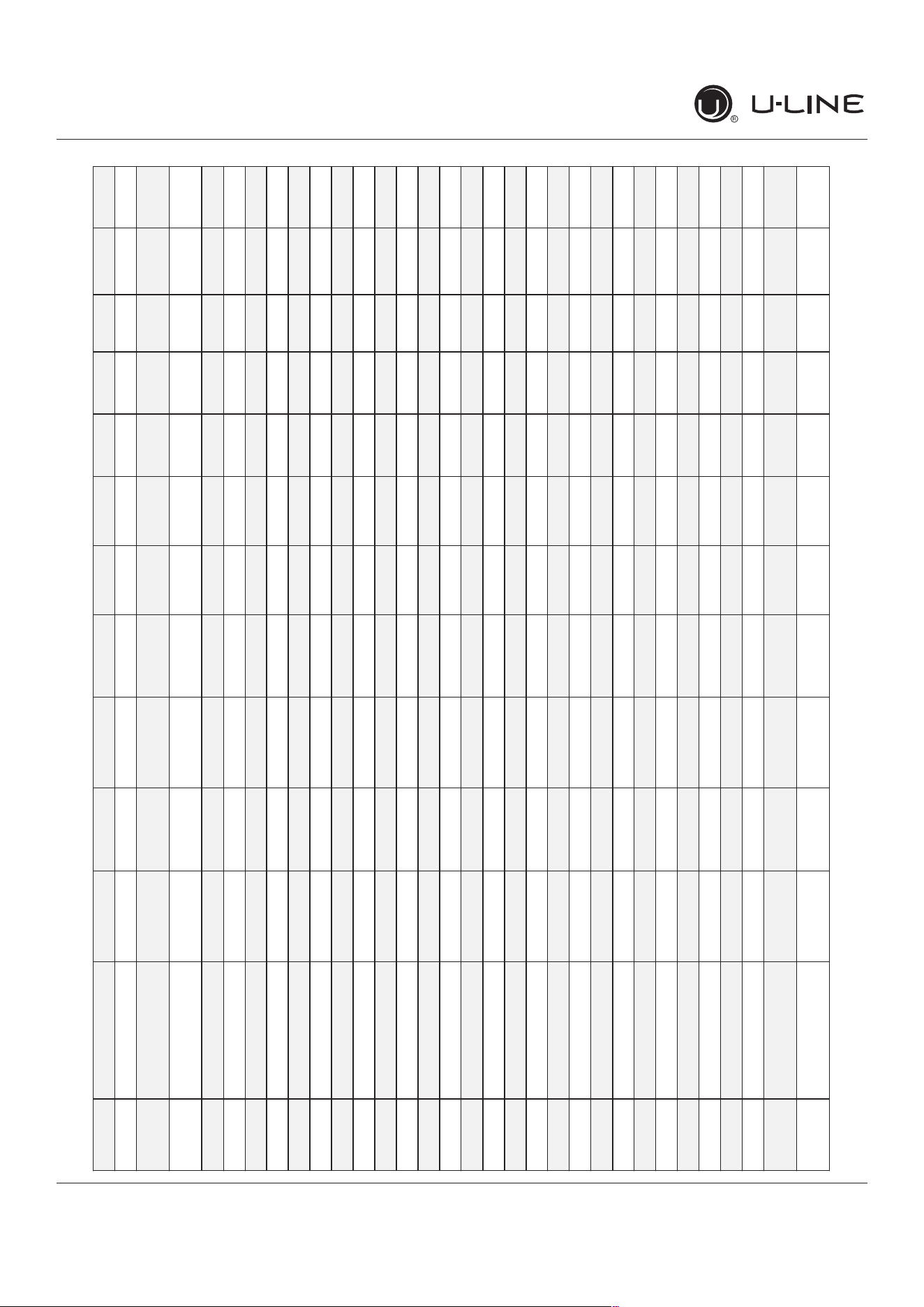
REGRIGERATION SYSTEM DIAGNOSIS GUIDE
System
Condition
Suction
Pressure
Suction
Line
Compressor
Discharge
Condenser Capillary
Tube
Evaporator Wattage
Normal Normal Slightly
below room
temperature
Very hot Very hot Warm Cold Normal
Overcharge Higher than
normal
Very cold
may frost
heavily
Slightly warm
to hot
Hot to warm Cool Cold Higher than
normal
Undercharge Lower than
normal
Warm-
near room
temperature
Hot Warm Warm Extremely
cold near
inlet - Outlet
below room
temperature
Lower than
normal
Partial
Restriction
Somewhat
lower than
normal vacuum
Warm-
near room
temperature
Very hot Top passes
warm -
Lower
passes cool
(near room
temperature)
due to liquid
Room
temperature
(cool) or
colder
Extremely
cold near
inlet - Outlet
below room
temperature
backing up
Lower than
normal
Complete
Restriction
In deep
vacuum
Room
temperature
(cool)
Room
temperature
(cool)
Room
temperature
(cool)
Room
temperature
(cool)
No
refrigeration
Lower than
normal
No Gas 0 PSIG to 25” Room
temperature
(cool)
Cool to hot Room
temperature
(cool)
Room
temperature
(cool)
No
refrigeration
Lower than
normal
40
USER GUIDE
u-line.com
CompressorSpeci�cations
Electrocution can cause death or serious injury.
Burns from hot or cold surfaces can cause serious
injury. Take precautions when servicing this unit.
Disconnect the power source.
Do not stand in standing water when working
around electrical appliances.
Make sure the surfaces you touch are not hot or
frozen.
Do not touch a bare circuit board unless you are
wearing an anti-static wrist strap that is grounded
to an electrical ground or grounded water pipe.
Handle circuit boards carefully and avoid touching
components.
CompressorSpeci�cations
FMXA9C
REFRIGERANT R600A
VOLTAGE 230 VAC
FREQUENCY 43-134 Hz
START WINDING 20 Ohm at 77
o
F
RUN WINDING 20 Ohm at 77
o
F
RUN TO START 20 Ohm at 77
o
F
LRA 1.7 A
FLA 1.7 A
STARTING DEVICE Inverter CF02C05
OVERLOAD Inverter CF02C05
*All resistance readings are
+
10%
DANGER
!
41
USER GUIDE
u-line.com
Troubleshooting Extended
Troubleshooting - Extended
CAUTION
!
Never attempt to repair or perform maintenance
on the unit until the main electrical power has
been disconnected from the unit.
SPECIFIC ERRORS AND ISSUES
The advanced diagnostic capabilities of the electronic
controls utilized on the 1, 3, and 5 Class units allow for
easy and thorough troubleshooting.
Navigation of the control is the key and is explained in
the CONTROL OPERATION section of the manual, along
with control button layout, control function descriptions,
a service mode menu and service menu selection
explanations.
Vericationoftemperatureandthermistorperformancecan
beidentiedbydirectlyviewingthermistorreadingsinthe
service mode.
Included in this section are some diagnostic tips and of
course, if additional help is required, please contact the
U-Line Corp, “Customer Care Facility” at +1.800.779.2547
for assistance.
NORMAL OPERATING SOUNDS
All models incorporate rigid foam insulated cabinets to
providehighthermaleciencyandmaximumsound
reduction for its internal working components. Despite
this technology, your model may make sounds that are
unfamiliar.
Normal operating sounds may be more noticeable because
of the unit’s environment. Hard surfaces such as cabinets,
wood,vinylortiledoorsandpaneledwallshavea
tendencytoreectnormalapplianceoperatingnoises.
Listed below are common refrigeration components with a
brief description of the normal sounds they make. NOTE:
Your product may not contain all the components listed.
• Compressor: The compressor makes a hum or pulsing
sound that may be heard when it operates.
• Evaporator:Refrigerantowingthroughanevaporator
may sound like boiling liquid.
• Condenser Fan: Air moving through a condenser may
be heard.
• Automatic Defrost Drain Pan: Water may be heard
dripping or running into the drain pan when the unit is
in the defrost cycle.
Solenoid Valves: An occasional clicking sound may be
heard as solenoid valves are operated.
42
USER GUIDE
u-line.com
Troubleshooting Extended
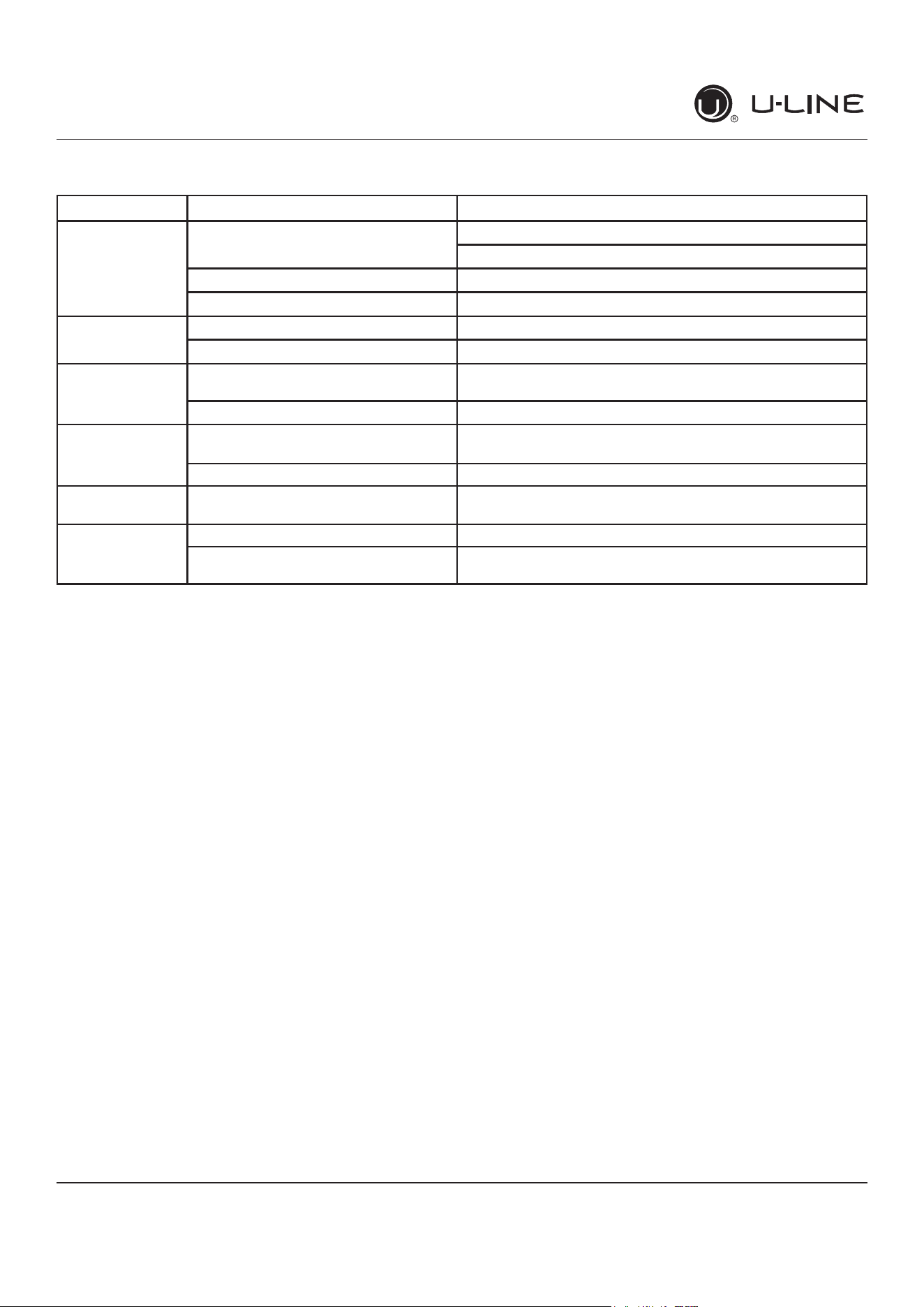
TROUBLESHOOTING GUIDE
Concern Potential Causes Action
Not Cooling Compressor overheating Verifyproperairowthroughcondenser.Iscondenserclean?
Conrmcondenserfanoperation.
Compressor not operating Test overload and relay, replace as needed.
Compressor operating - no cooling Refer to System Diagnosis Guide.
Frozen Product Control set too cold Adjust Set Point Temp accordingly.
Thermistor failure Check Error Log in Service Mode, OHM thermistor.
Frost Buildup
Inside Unit
Door Ajar or Restricted from Closing Check door clearance to adjoining cabinetry. Check
distribution of product in unit.
Thermistor failure OHM thermistor
Display Not
Working
Display unplugged Verifythatbothendsofthedisplaywiringarermly
connected.
Display wiring broken or damaged Perform continuity test of wiring and replace as needed.
Interior Lights Not
Working
Door switch misaligned or defective Check the function of reed switch and door magnet
adjustment.
Noisy Refrigeration tubing touching cabinet Carefully reposition tubing.
Fan blade obstruction (wiring, foam
insulation, packaging material)
Remove obstruction.
43
USER GUIDE
u-line.com
Troubleshooting Extended
MAIN CONTROL
The main control board is very robust and is rarely the
cause of system issues. It is important to fully diagnose
the board for any suspected failures before attempting
to remove the board for replacement or service. Follow
the guidelines below to fully test and diagnose the main
control.
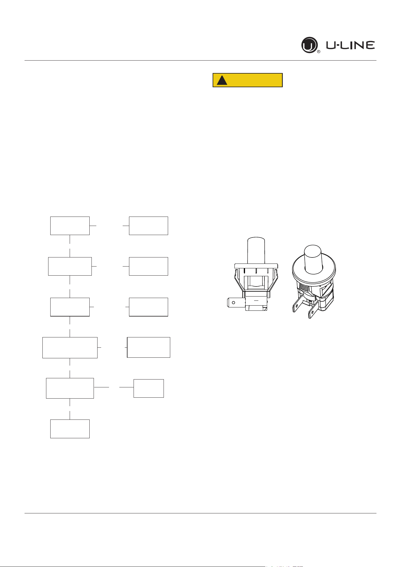
Power Fault
If the unit does not (or seems to not) power on, follow the
owchartbelowtohelpdiagnosetheissue.Beforebegin-
ningitisimportanttorstverifytheunitisnotsimplyset
to sabbath mode.
Check Voltage
At Wall Outlet
Verify Voltage At
Main Control
Voltage Input
Check Fuse F1
For Continuity
Replace
Plunger Switch
Replace Main
Board
Replace
Fuse
Replace
Power Cord
Alert Customer
Of Power Failure
Is the Plunger
Switch Operating
Properly?
Inspect
Customer UI
and Data Cable
Connect Test Display
Cycle Power And Check
For Operation
No Voltage
No Voltage
Voltage
Continuity
Operating
Not Operating
No Continuity
No
Yes
Voltage
CAUTION
!
Precautions must be taken while working with
live electrical equipment. Be sure to follow
proper safety procedures while performing tests
on live systems.
PLUNGER SWITCH
A plunger switch is used to monitor door state. When the
door is closed it comes into contact with the plunger which
closesacircuitwhichturnsthelightanddisplayo�.When
the door is open the plunger moves outward and opens the
circuit. If the door is left open for longer than 5 minutes
the switch will trigger an error code and set an audible
warning.
44
USER GUIDE
u-line.com
Control Operation-Service
Control Operation-Service
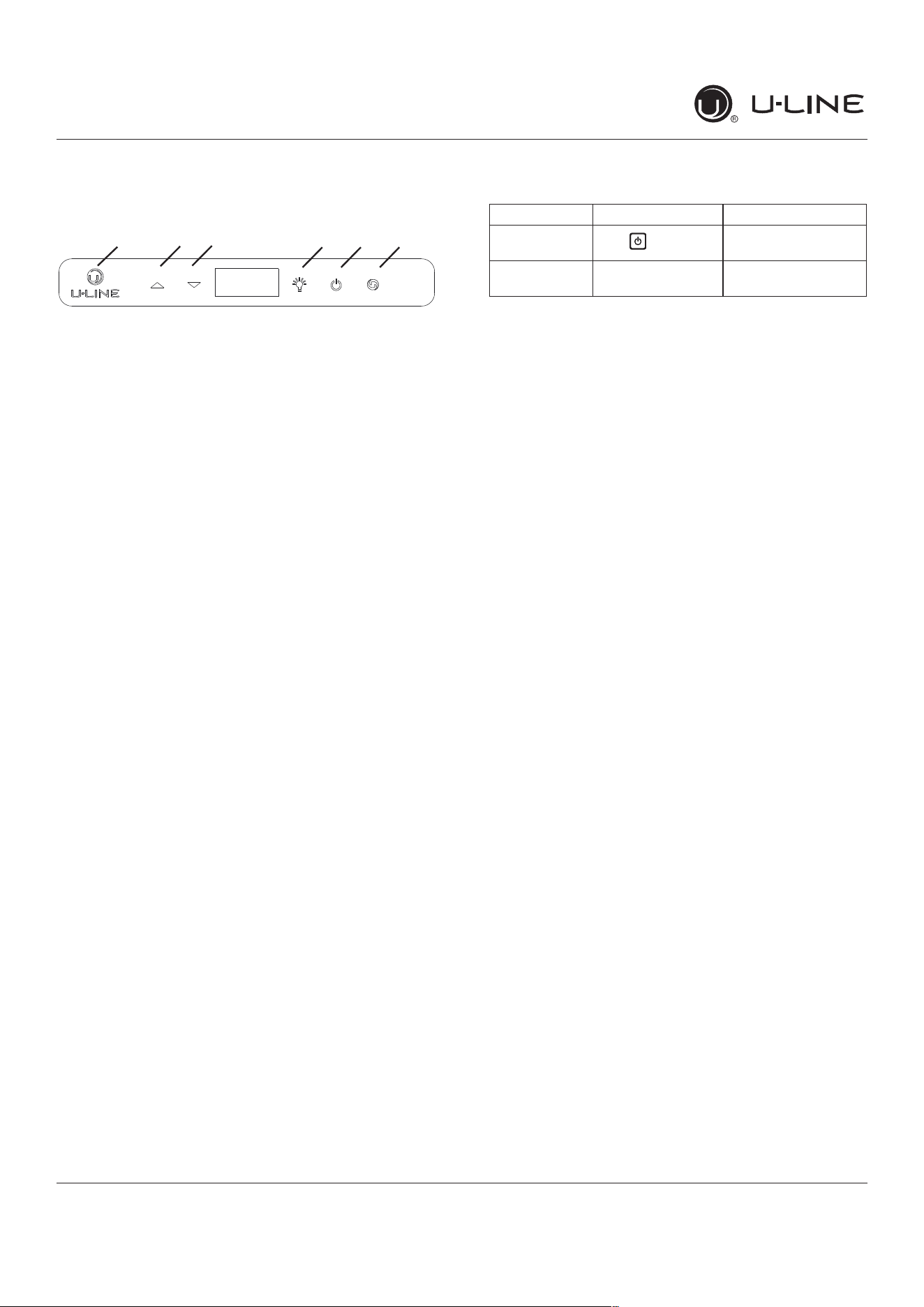
UI BUTTON LAYOUT
1. Hidden Button
2. Up Button
3. Down Button
4. Light Button
5. Power Button
6. Clean Button
-Access Service Menu
-No LED directly above. All LEDs turn on with button
-Increases temperature
-Navigates through service menu
-Decreases temperature
-Navigates through service menu
-Activates light for 3 hours on select models
-Used to select items in service menu
-Turnsunito�/on
-Activates Clean Cycle on select models
-Toggles between zones in Dual-Zone models
CONTROL FUNCTION GUIDE
SHOWROOM MODE
This mode is designed to show units in a display
environment. When in this mode the only functions will be
the control and cabinet lights. The compressor, fans, etc.
willnotoperate.Toenter/exitthismodeholdthelightkey
andthepowerkeyfor5seconds.Thedisplaywillash
onceandbeepandthedegreesymbolwillbegintoash.
Whenthedegreesymbolisashingtheunitwillallowthe
use of the control for demonstrations. The unit can be left
inthismodeindenitely.
SERVICE MODE
This mode has options available for service diagnostics.
Toenterthemodeholdthehiddenkeyfor10seconds.
Thedisplaywillshow“0.”Wheninthismodeusetheup
and down arrows to select the desired option. The LIGHT
keyistheENTERkeyandwillinitiatethefunction.If
changingasetting,youmustpresstheLIGHTkeyagain
toretainthechangedsetting.Toexittheservicemode
scrolltooption“0”andpresstheLIGHTkey.Afterve
minutesofnottouchinganykeysthemodewillalsoexit
automatically.
1 2 3 4 5 6
FUNCTION COMMAND DISPLAY/OPTIONS
ON/OFF
Press and release
Unit will immediately
turnONorOFF
Sabbath Mode See“SabbathMode”
section
45

USER GUIDE
u-line.com
Control Operation-Service
SERVICE MODE GUIDE SERVICE MODE GUIDE
0.Exit
1.Thermistor1temperaturenotincludingo�sets.
2.Thermistor2temperaturenotincludingo�sets.
3.Thermistor3temperaturenotincludingo�sets.
4.Thermistor4temperaturenotincludingo�sets.
5.Thermistor1o�set.(+/-10)
6.Thermistor2o�set.(+/-10)
7.Thermistor3o�set.(+/-10)
8.Thermistor4o�set.(+/-10)
9. Thermistor 2 set point
10.Thermistor3setpoint.
11. Thermistor 4 set point.
12.DefrostInterval(0to99hr)
13.Defrostduration(0to99min)
14.ErrorLog(SeeAppxD)
15.Clearerrorlog(holdlightkeyuntilcleared)
16.Thermistor1di�erential(+5)
17.Thermistor3di�erential(+5)
18.Evaporatorfanondelay(0to99sec)
19.Evaporatorfano�delay(0to99sec)
20.Individualcomponenttoggle
-Option#0–Exit
-Option#1–Relay1
-Option#2–Relay2
-Option#3–Relay3
-Option#4–Relay4
-Option#5–Relay5
-Option#6–Relay6
-Option#7–DCOutput1
-Option#8–DCOutput2
-Option#9–DCOutput3
-Option#10–DCOutput4
-Option#11–DCOutput5
-Option#12–Serialoutput(Compressor)
21. Model number
22. Light All Segments
23.ActivateDefrost/Harvest-pressandholdfor3seconds
toactivatedefrost/harvest
24. Defaults- press and hold for 3 seconds to restore all
values to factory defaults.
25.MainSoftware(Displayonly)
26.LiveLogPeriod(frequencythatdataisoutputto
diagnosticsport)
27.Factorytestmode(0=O�,1=On)
28.CompressorRPM
29.Freezetimeadjust(Model54only)
30.Harvesttimeadjust(Model54only)
31.Lowtempalarmlimit(Model55only)
32.Hightempalarmlimit(Model55only)
1. THERMISTOR 1 — ZONE
Thisshowsthepurethermistorreadingwithnoo�sets
takenintoaccount.
2. THERMISTOR 2 — EVAPORATOR
Thisshowsthepurethermistorreadingwithnoo�sets
takenintoaccount.
3. Does not apply to this model.
4. Does not apply to this model.
5. THERMISTOR 1 — ZONE OFFSET
(DONOTMAKEANADJUSTMENTTOTHISWITHOUT
CONTACTINGTECHLINE:800-779-2547)
This calibration is only to be used if actual
temperatureatthermistor#1iso�fromsetpoint.
Byadjustingtheo�sethigherwecanforcetheunit
to drive the temperature down below the set point.
(example:adjustingfrom0to+2willdroptheunit
temperature2degrees)
6. THERMISTOR 2 — EVAPORATOR OFFSET
(DONOTMAKEANADJUSTMENTTOTHISWITHOUT
CONTACTINGTECHLINE:800-779-2547)
7. Does not apply to this model.
8. Does not apply to this model.
9. THERMISTOR 2 — SET POINT MINUS OFFSET
Thisshowsthethermistorreadingwitho�setstaken
into account.
10.Doesnotapplytothismodel.
11. Does not apply to this model.
12. ADJUST DEFROST INTERVAL — 3 TO 24
HOURS
Thiswilladjusttheintervalbetweendefrostsfrom
3to24hours.Adjustingfromthefactorysettings
may cause undesired temperature in the refrigerator
section.
13. ADJUST DEFROST DURATION — 0 TO 99
MINUTES
Thelengthofthedefrostcanbeadjusted0to99
minutes long. The other defrost parameters still apply.
Lengthening a defrost may cause higher than normal
temperatures in the refrigerator section.
14. VIEW ERROR LOG
A list of errors in the order they occurred will scroll
on the display. All errors are logged in memory. Only
door error is displayed on the display and has an
audible signal.
E0:Door1(upper)open.
E1: Thermistor 1 open.
E2: Thermistor 2 open.
46
USER GUIDE
u-line.com
Control Operation-Service
E3: Thermistor 3 open.
E4:Thermistor4open(Doesnotapplytothismodel).
E5: Thermistor 1 shorted.
E6: Thermistor 2 shorted.
E7: Thermistor 3 shorted.
E8: Thermistor4shorted(Doesnotapplytothis
model).
E9:Door2(lower)open.
P1:PumpCircuitopen(Doesnotapplytothismodel).
15: CLEAR ERROR LOG
To clear errors, press and hold(5seconds)when
CLRisashing.
16: THERMISTOR - 1 DIFFERENTIAL
Thisnumbershouldnotbeadjusted.
17. Does not apply to this model.
18. THIS NUMBER SHOULD NOT BE ADJUSTED
19. THIS NUMBER SHOULD NOT BE ADJUSTED
20.INDIVIDUAL COMPONENT TOGGLE
21. MODEL NUMBER INDICATOR
Displaysthetwo-digitmodelnumberofthespecic
unit. See Model list table.
22. LIGHT ALL LED SEGMENTS
This will illuminate all the LEDs on the display to
ensuretheyworkproperly
23. ACTIVATE DEFROST /HARVEST
-Press and hold for 3 seconds to activate
24.
FACTORY DEFAULTS
-Press and hold for 3 seconds to restore all values to
factory defaults
25. MAIN SOFTWARE
26.
Does not apply to this model
27.
FACTORY TEST MODEL
0=O�,1=On
28.
COMPRESSOR RPM
29.
FREEZE TIME ADJUST (MODEL 54 ONLY)
30.
HARVEST TIME ADJUST (MODEL 54 ONLY)
31.
LOW TEMP ALARM LIMIT (MODEL 55 ONLY)
32.
HIGH TEMP ALARM LIMIT (MODEL 55 ONLY)
Display # Relay / Output
-Option#0–Exit
-Option#1–Relay1
-Option#2–Relay2
-Option#3–Relay3
-Option#4–Relay4
-Option#5–Relay5
-Option#6–Relay6
-Option#7–DCOutput1
-Option#8–DCOutput2
-Option#9–DCOutput3
-Option#10–DCOutput4
-Option#11–DCOutput5
-Option#12–Serialoutput(Compressor)
SEE RELAY / OUTPUT CHART
47
USER GUIDE
u-line.com
Control Operation-Service
MODEL LIST
Model # Model
1 *HBV315-***1A
2 *HBV315-***2A
3 *HBV318-***1A
4 *HBV324-***1A
5 *HBV324-***2A
6 *HBV336-***1A
7 *HBV515-***1A
8 *HBV515-***2A
9 *HBV524-***1A
10 *HBV524-***2A
11 *HCL315-***1A
12 *HCL315-***2A
13 *HDR324-***1A
14 *HDR324-***2A
15 *HFZ324-***1A
16 *HFZ324-***2A
17 *HRE315-***1A
18 *HRE315-***2A
19 *HRE318-***1A
20 *HRE324-***1A
21 *HRE324-***2A
22 *HRE336-***1A
23 *HRE515-***1A
24 *HRE515-***2A
25 *HRE524-***1A
26 *HRE524-***2A
27 *HRE324-***1A
28 *HRE324-***2A
29 *HKR524-***1A
30 *HKR524-***2A
31 *HWC315-***2A
32 *HWC315-***1A
33 *HWC318-***1A
34 *HWC324-***2A
35 *HWC324-***1A
36 *HWC515-***2A
37 *HWC515-***1A
38 *HWC524-***1A
39 *HWC524-***2A
40 *HWC336-***1A
41 *HBD324-***1A
42 *HBD324-***2A
43 *HBD524-***1A
44 *HBD524-***2A
45 *HWD324-***2A
46 *HWD324-***1A
47 *HWD524-***2A
48 *HWD524-***1A
49 *HRF124-***2A
50 *HRF124-***1A
51 *HRI124-***2A
52 *HRI124-***1A
53 NuggetR134A
54 Grid Ice
55 MedicalRefrigerator
56 Fullsize
57 NuggetR600
PROGRAMMING THE UNIT TO CORRECT
MODEL NUMBER
1. Disconnect the unit from power source.
2. Push and hold the U-Line button.
3. While still holding the U-Line button, plug the
unit into the appropriate power source.
4.Whentheashingdigitsappear(3-5seconds),
use the up and down arrow buttons to select the
appropriate model number*. or
*(SeeAbove“ModelList”)
5. Press the light bulb button once.
6.Thedisplaywillblink,andthenwillappearasthe
programmed display.
48
USER GUIDE
u-line.com
Control Operation-Service
Program Model Relay 1 Relay 2 Relay 3 Relay 4 Relay 5 Relay 6 DC1 DC2 DC3 DC4 DC5
53
NuggetIce,R134 Comp/Fan - Dump Valve ReservoirFill Auger Water Main Light 1 Light 2 - - CondFan
57
NuggetIce,R600 Water Main Water Dis-
pense
Dump Valve ReservoirFill Auger CondFan Light 1 Light 2 - - CondFan
11
Clear Ice, 3 Class Compressor Water Dis-
pense
Circ Pump Water Inlet Hot Gas
Valve
CondFan Light 1 Light 2 - - CondFan
01
**BV315-***1A Compressor - - - - - Light 1 Light 2 EvapFan - CondFan
03
**BV318-***1A Compressor - - - - - Light 1 Light 2 EvapFan - CondFan
04
**BV324-***1A Compressor - - - - - Light 1 Light 2 EvapFan - CondFan
06
**BV336-***1A Compressor Top/LeftValve Bot/RightValve - - - Light 1 Light 2 EvapFan EvapFan2 CondFan
07
**BV515-***1A Compressor - - - - - Light 1 Light 2 EvapFan - CondFan
09
**BV524-***1A Compressor - - - - - Light 1 Light 2 EvapFan - CondFan
13
**DR324-***1A Compressor Mullion Heater - - - - Light 1 Light 2 EvapFan EvapFan2 CondFan
15
**FZ324-***1A Compressor - - - Heater CondFan Light 1 Light 2 EvapFan - CondFan
17
**RE315-***1A Compressor - - - - - Light 1 Light 2 EvapFan - CondFan
19
**RE318-***1A Compressor - - - - - Light 1 Light 2 EvapFan - CondFan
20
**RE324-***1A Compressor - - - - - Light 1 Light 2 EvapFan - CondFan
22
**RE336-***1A Compressor Top/LeftValve Bot/RightValve - - - Light 1 Light 2 EvapFan EvapFan2 CondFan
23
**RE515-***1A Compressor - - - - - Light 1 Light 2 EvapFan - CondFan
25
**RE524-***1A Compressor - - - - - Light 1 Light 2 EvapFan - CondFan
27
**RE324-***1A Compressor - - - - - Light 1 Light 2 EvapFan - CondFan
29
**KR524-***1A Compressor - - - - - Light 1 Light 2 EvapFan - CondFan
32
**WC315-***1A Compressor - - - - - Light 1 Light 2 EvapFan - CondFan
33
**WC318-***1A Compressor - - - - - Light 1 Light 2 EvapFan - CondFan
35
**WC324-***1A Compressor - - - - - Light 1 Light 2 EvapFan - CondFan
37
**WC515-***1A Compressor - - - - - Light 1 Light 2 EvapFan - CondFan
38
**WC524-***1A Compressor - - - - - Light 1 Light 2 EvapFan - CondFan
40
**WC336-***1A Compressor Top/LeftValve Bot/RightValve - - - Light 1 Light 2 EvapFan EvapFan2 CondFan
41
**BD324-***1A Compressor Top/LeftValve Bot/RightValve - - - Light 1 Light 2 EvapFan EvapFan2 CondFan
43
**BD524-***1A Compressor Top/LeftValve Bot/RightValve - - - Light 1 Light 2 EvapFan EvapFan2 CondFan
46
**WD324-***1A Compressor Top/LeftValve Bot/RightValve - - - Light 1 Light 2 EvapFan EvapFan2 CondFan
48
**WD524-***1A Compressor Top/LeftValve Bot/RightValve - - - Light 1 Light 2 EvapFan EvapFan2 CondFan
50
**RF124-***1A Compressor - - Pan Defrost
Heater
CondFan Light 1 Light 2 EvapFan - CondFan
52
**RI124-***1A Compressor Icemaker2 Icemaker1 Pan Defrost
Heater
CondFan Light 1 Light 2 EvapFan - CondFan
Relay / Output Chart
49
USER GUIDE
u-line.com
Thermistor
Evaporator Thermistor
If the evaporator thermistor fails, the unit will rely on a
preset defrost timer during defrost cycles. The unit will
otherwise operate normally. Refer to defrost section.
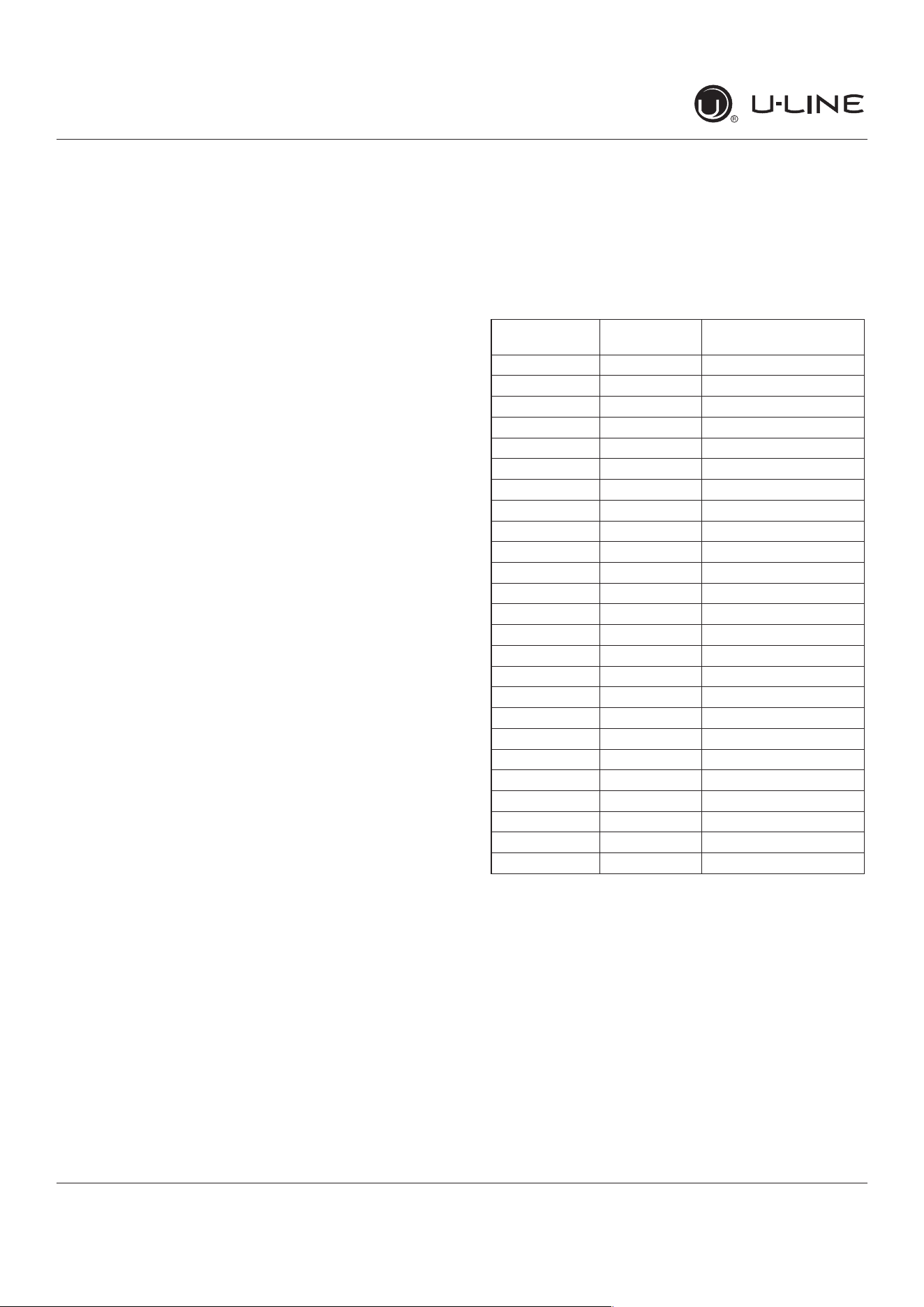
Thermistor Resistance Data
Thermistors
Thermistors are used for various temperature readings.
Thermistors provide reliable temperature readings
using a resistance which varies based on surrounding
temperatures. If a faulty thermistor is suspected it may be
tested using an accurate ohmmeter.
Both thermistors in the unit are identical. If a thermistor
is suspected of being defective, the resistance can be
veri�ed.Placethethermistorinanicewaterbath,the
resistance should read 16.1k Ohms +/-5% on your meter.
Thermistor connections must be kept clean. A thermistor
connection that has become corroded can cause resistance
values from the thermistor to change as they pass through
a dirty connection to the board.
It is for that reason that we apply dielectric grease to all of
our thermistor connections. Dielectric grease will help to
keep thermistor connections clean and dry.
If you change a thermistor in the unit please re-apply
dielectric grease to the connection. If you encounter
a dirty thermistor connection, you should replace the
thermistor and the thermistor harness.
Thermistor error information can be found in the Control
Operations - Service section.
This unit has two thermistors.
Thermistor one (Zone):
Located along the right hand side wall. It is used to
maintain the operating temperature within that zone.
Thermistor two (Evaporator):
Located on the evaporator. It is used for defrost.
THERMISTOR FAILURE
Zone Thermistor
If the zone thermistor in the unit fails, the unit will
continuetocoolinabackupmode(SelfPreservation
Mode) to preserve the integrity of the contents. The unit
will otherwise operate normally.
* (+/
-
5%)
Temp (F) Temp (C)
Nominal Resistance
(OHMS)*
-40 -40 169157
-31 -35 121795
-22 -30 88766
-13 -25 65333
-4 -20 48614
5 -15 36503
14 -10 27681
23 -5 21166
32 0 16330
41 5 12696
50 10 9951
59 15 7855
68 20 6246
77 25 5000
86 30 4029
95 35 3266
104 40 2665
113 45 2186
122 50 1803
131 55 1495
140 60 1247
149 65 1044
158 70 879
167 75 743
176 80 631
50
USER GUIDE
u-line.com
Defrost
Defrost
Thisunitdefrostsevery12hoursofcompressorruntimefor45minutes.Ifyouhaveveri�edthattheunitdoes
not have an ambient air leak, utilize the Control Operation - Service section and adjust unit to defrost every 9
hours for 60 minutes. Also, adjust the #2 thermistor to -4 instead of 0.
51
USER GUIDE
u-line.com
Remove Fan and Cover
Remove Fan and Cover
CONVECTION COOLING
This unit is equipped with an advanced convection cooling
system. Convection cooling stabilizes cabinet temperature,
coolsproductfasterandincreasesenergyeciency.
Evaporator Fan
The evaporator fan is responsible for circulating warm air
from the refrigeration zone, past the evaporator and back
into the refrigerated zone.
The evaporator fan is factory set to have a 1 minute delay
at the beginning of a cooling cycle. This delay gives the
evaporator time to cool properly before warm air is passed
over it. The fan will continue to run for an additional 2
minutes at the end of a cooling cycle. Fan delay times can
bemodi�edthroughtheservicemenu.
Evaporator fan operation is also determined by door switch
state. If the door switch circuit opens, the fan will stop.
When the door switch circuit is closed the fan will either
continue running with the cooling cycle, or if not currently
cooling, the fan will run for 1 minute to circulate air and
clear any condensation that may have appeared on glass
doors and shelves.
Note: If the unit is set to sabbath mode, the evaporator
fan will no longer respond to the state of the door switch.
Inordertooperateeciently,theevaporatorfanblade
and vents should be unobstructed and free of any dust
buildup.
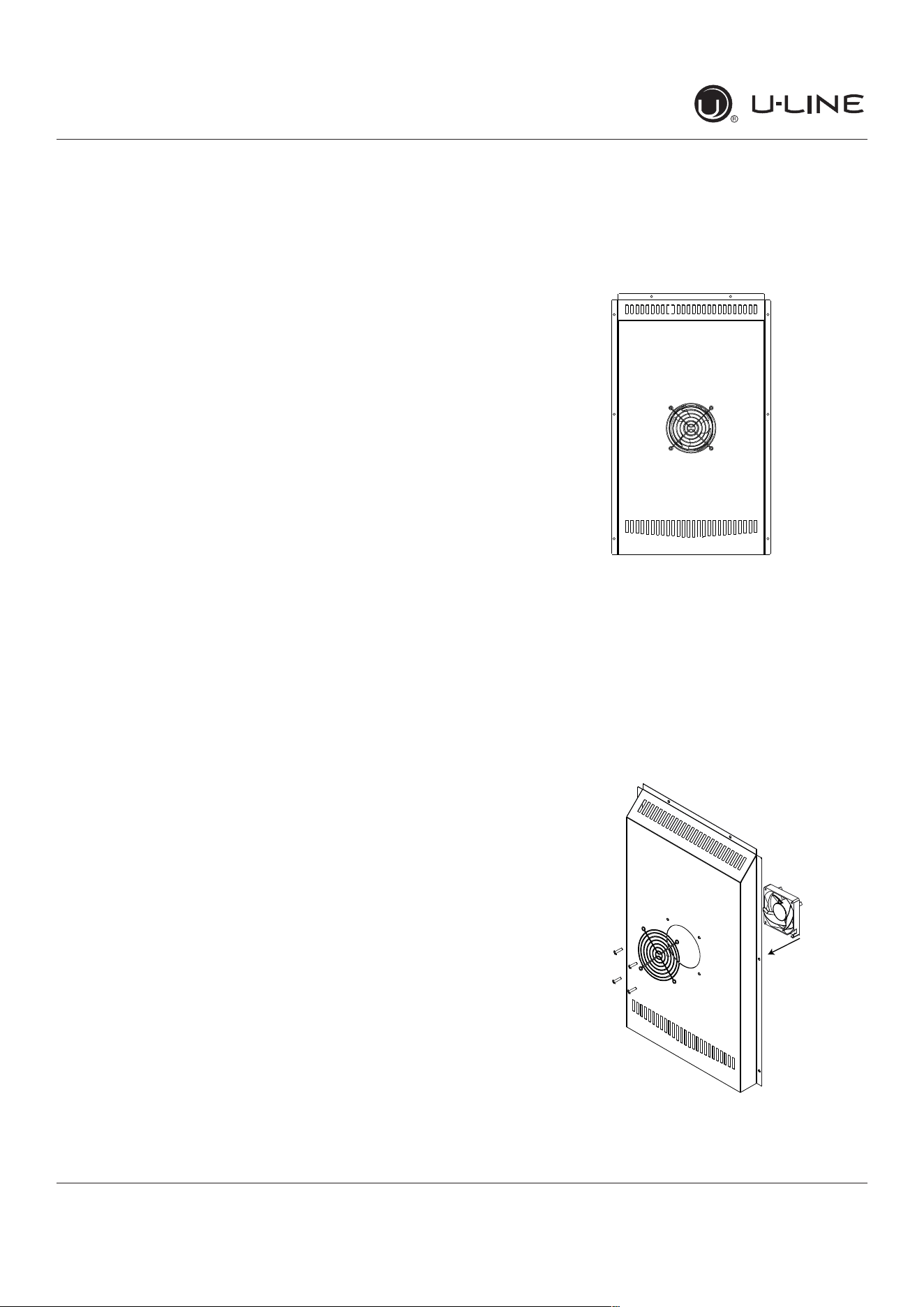
Evaporator Fan Replacement
Should the evaporator fan need to be replaced follow the
steps below.
1. Remove any product from the unit.
2. Remove unit from cabinetry to access rear.
3. Disconnect power to the unit.
4. Remove back panel from unit.
5. Disconnect fan electrical connection at rear of unit.
6. Remove insulating foam from refrigerant line pass-
through hole as needed to gain clearance for fan plug.
7. Remove internal shelving.
8. Remove 8 evaporator cover screws.
9. Grasp evaporator cover, pull forward and up as bottom
of cover is installed behind the front edge of the drain
trough.
10. While pulling the evaporator cover clear of the unit, it
may be necessary to use your free hand to manipulate
the fan plug end through the pass-through hole.
11. Remove the 4 screws mounting the fan shroud to the
evaporator plate.
12. Remove and replace fan. Take special care to properly
route fan wire.
A
ir
Fl
ow
52
USER GUIDE
u-line.com
Remove Fan and Cover
NOTICE
Fan must be oriented to pull air in through lower
evaporator cover vents and push air out at fan
mounting location.
13. Installation is the reverse of removal.
14. Care must be taken to assure the bottom of the
evaporator cover is reinstalled behind the front edge of
the train trough.
15. Use sealant gum to seal any openings at rear of unit
before replacing rear cover.
16. Reinstall unit taking care to level, space and secure as
found.
53

Copyright © 2020 U-Line Corporation. All Rights Reserved. | Publication Number 30379 | 11/2020 Rev. O
U-LineCorporation(U-Line)LimitedWarranty
OneYearLimitedWarranty
For one year from the date of original purchase, this warranty covers all parts and labor to repair or replace any part of the product that
proves to be defective in materials or workmanship. For products installed and used for normal residential use, material cosmetic defects
are included in this warranty, with coverage limited to 60 days from the date of original purchase. All service provided by U-Line under the
above warranty must be performed by a U-Line factory authorized servicer, unless otherwise specified by U-Line. Service provided during
normal business hours.
TwoYearLimitedWarranty(5ClassProduct)
For two years from the date of original purchase, this warranty covers all parts and labor to repair or replace any part of the product that
proves to be defective in materials or workmanship. For products installed and used for normal residential use, material cosmetic defects
are included in this warranty, with coverage limited to 60 days from the date of original purchase. All service provided by U-Line under the
above warranty must be performed by a U-Line factory authorized servicer, unless otherwise specified by U-Line. Service provided during
normal business hours.
AvailableSecond&ThirdYearLimitedWarranty
In addition to the standard one and two year warranties outlined above, U-Line offers a one year extension of the warranties from the date
of purchase, free of charge. To take advantage of this extension, you must register your product with U-Line within 60 days from the date
of purchase at u-line.com and provide proof of purchase.
FiveYearSealedSystemLimitedWarranty
For five years from the date of original purchase, U-Line will repair or replace the following parts, labor not included, that prove to be
defective in materials or workmanship: compressor, condenser, evaporator, drier, and all connecting tubing. All service provided by U-Line
under the above warranty must be performed by a U-Line factory authorized servicer, unless otherwise specified by U-Line. Service
provided during normal business hours.
Terms
These warranties apply only to products installed in any one of the fifty states of the United States, the District of Columbia, or the ten
provinces of Canada. The warranties do not cover any parts or labor to correct any defect caused by negligence, accident or improper use,
maintenance, installation, service, repair, acts of God, fire, flood or other natural disasters. The product must be installed, operated, and
maintained in accordance with your product’s User Guide.
The remedies described above for each warranty are the only ones that U-Line will provide, either under these warranties or under any
warranty arising by operation of law. U-Line will not be responsible for any consequential or incidental damages arising from the breach of
these warranties or any other warranty, whether express, implied, or statutory. Some states do not allow the exclusion or limitation of
incidental or consequential damages, so the above limitation or exclusion may not apply to you. These warranties give you specific legal
rights, and you may also have other rights which vary from state to state.
Any warranty that may be implied in connection with your purchase or use of the product, including any warranty of merchantability or any
warranty fit for a particular purpose is limited to the duration of these warranties, and only extends to five years in duration for the parts
described in the section related to the five year limited warranty above. Some states do not allow limitations on how long an implied warranty
lasts, so the above limitations may not apply to you.
• The warranties only apply to the original purchaser and are non-transferable.
• The second, third, and five year warranties cover products installed and used for normal residential or designated marine use only.
• The warranties apply to units operated outside only if designed for outdoor use by model and serial number.
• U-Line Commercial products are covered by the one year and 5 year limited warranties and are not eligible for the second and
third year limited warranties.
• Replacement water filters, light bulbs, and other consumable parts are not covered by these warranties.
• The start of U-Line’s obligation is limited to four years after the shipment date from U-Line.
• In-home instruction on how to use your product is not covered by these warranties.
• Food, beverage, and medicine loss are not covered by these warranties.
• If the product is located in an area where U-Line factory authorized service is not available, you may be responsible for a trip
charge or you may be required to bring the product to a U-Line factory authorized service location at your own cost and expense.
• Units purchased after use as floor displays, and/or certified reconditioned units, are covered by the limited one year warranty only
and no coverage is provided for cosmetic defects.
• Signal issues related to Wi-Fi connectivity are not covered by these warranties.
For parts and service assistance, or to find U-Line factory authorized service near you, contact U-Line:
8900 N. 55
th
Street,Milwaukee,WI53223•u-line.com•onlineservice@u-line.com•+1.414.354.0300
54