8
ASSEMBLY
NOTE: This Operator’s Manual covers several models. Tractor
features may vary by model. Not all features in this manual are
applicable to all tractor models and the tractor depicted may
differ from yours.
NOTE: All references in this manual to the left or right side and
front or back of the tractor are from the operating position only.
Exceptions, if any, will be specified.
Preparation
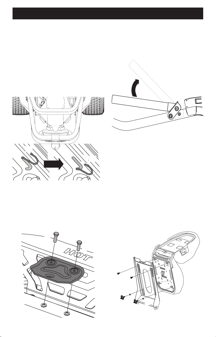
MANUALLY MOVING THE TRACTOR
1. To engage the transmission bypass rods, pull the rod back (a)
and into lower section of “J” slot. Repeat on opposite side.
See Figure 1.
(a)
(b)
Figure 1
2. After moving tractor, reverse Step 1 to disengage the
bypass rods.
3. Remove the deck wash system nozzle adapter from the
manual bag, store for future use.
INSTALL HITCH IF NECESSARY
1. Locate Hitch (a) and install on the rear of the frame using the
two hex washer screws (b) provided. See Figure 2.
(a)
(b)
(b)
Figure 2
NOTE: Hitch and hex washer screws will be in the hardware pack.
REPOSITION UPPER HOOP IF NECESSARY
Upper hoop may be positioned down for shipping purposes:
1. Remove the two hex washer screws (a) partially installed on
the frame. See Figure 3.
(a)
(b)
(b)
Figure 3
2. Rotate the upper hoop (b) into position. See Figure 3.
3. Secure hoop in place with the hex washer screws removed
in Step 1. Torque the hex washer screws to 159-239 in-lbs
(18-27 N-m).
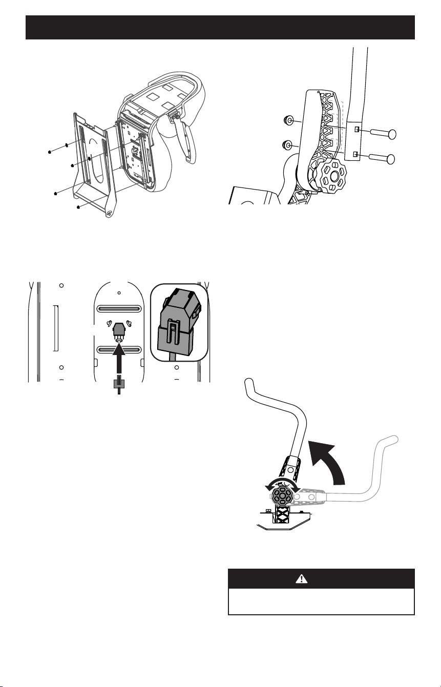
Install Operator’s Seat
KNOB ADJUST OR LEVER ADJUST
1. Cut any straps securing the seat assembly to the tractor.
Remove all packing material.
NOTE: Be careful not to cut the seat wiring harness.
2. Install the seat onto the seat pan (a) using hardware provided.
a. For a Knob Adjust seat insert bolts (b) in the rear holes
and lock washer (c) and knobs (d) in the front. Tighten
securely. See Figure 4.
(b)
(b)
(c)
(c)
(d)
(a)
(d)
Figure 4
9
ASSEMBLY
b. For a Lever Adjust seat use flange lock nuts (a) and flat
washers (b). See Figure 5.
(a)
(a)
(b)
(b)
(c)
(a)
(a)
Figure 5
3. If necessary, securely connect the seat switch wiring harness
(a) to the seat switch (b). See Figure 6. Secure excess wire
away from pinch points before continuing.
(a)
(b)
(a)
(b)
Figure 6
NOTE: Tractor will not operate without the seat switch wiring
harness connected.
Position Lapbar Drive Control Levers
The lapbar drive control levers can be adjusted up/down and
forward/backward for the operator’s comfort. Three height
positions are available and/or levers can be rotated forward or
rearward using the knob.
To adjust the lapbar drive control lever height, proceed as follows:
1. Remove the two carriage screws (a) and two flange lock nuts
(b) that secure the lapbar drive control lever (c) to the upper
handle adjuster (d). See Figure 7.
NOTE: The multi-tool (if equipped) can be used to make
this adjustment.
2. Move the lapbar drive control lever into one of three available
heights and secure in place with the carriage screws and
flange lock nuts. See Figure 7.
(b)
(b)
(a)
(a)
(c)
(d)
Figure 7
To adjust the lapbar drive control levers forward/rearward,
proceed as follows:
1. Rotate the knob (a) counter-clockwise to loosen the knob (a).
See Figure 8.
2. Lift and rotate the lapbar drive control lever into the
desired position.
3. Rotate the knob clockwise to secure the lapbar drive control
lever into position. See Figure 8.
4. If the lapbars do not line up after making the knob
adjustment, loosen nuts (b), align lapbars and re-tighten
nuts. Once this fine adjustment is made, the lapbars will align
when using the knob adjustment. See Figure 7.
(a)
Figure 8
Lower Discharge Chute Deflector
WARNING
Never operate the mower deck without the chute
deflector installed and in the down position.
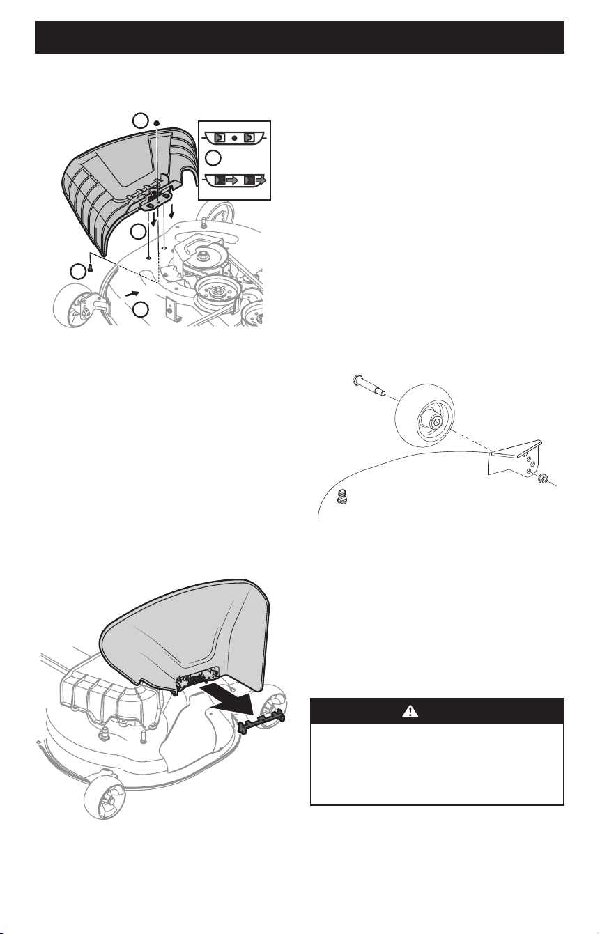
ATTACHING THE CHUTE DEFLECTOR IF NECESSARY
1. Remove the keys attached with a zip tie to the chute bracket.
2. Remove the flange lock nut and hex screw from the deck.
10
ASSEMBLY
3. Place the chute deflector on the deck, be sure to insert the
tabs on the chute deflector into the holes on the deck.
See Figure 9.
3
5
5
4
4
Figure 9
4. Slide the chute deflector toward the rear of the tractor until
the bolt hole in the chute deflector aligns with the hole in the
deck. See Figure 9.
5. Secure the chute deflector in place with the flange lock nut
and hex screw removed in Step 2. Tighten to 102-124 in-lbs
(11.5-14 N-m). Skip ahead to Setting Deck Wheels.
REMOVING THE STOP BRACKET IF NECESSARY
1. If the chute is shipped attached and with a stop bracket
holding the chute upright, the stop brackets must be
removed prior to operating the tractor.
2. Holding the chute deflector fully upward, remove the stop
bracket. Lower the chute deflector and discard the stop
bracket. See Figure 10.
Figure 10
Setting Deck Wheels (If Equipped)
NOTE: The deck wheels are an anti-scalp feature of the deck and
are not designed to support the weight of the cutting deck.
1. Move the tractor to a level surface, preferably pavement.
2. Check tire pressure, adjust if necessary. See tire side wall for
proper tire pressure.
3. Make sure the deck is level side-to-side and properly
pitched. See the Service and Maintenance section for deck
leveling information and instructions.
4. Place deck lift lever or knob in the desired mowing height
position and lower deck.
5. Check the wheels for contact or excessive clearance with the
surface below.
NOTE: The deck wheels should have between 1⁄4” (6.35 mm)
and 1⁄2” (12.7 mm) clearance above the ground.
6. Remove the lock nut (a) gauge wheel (b) and shoulder screw
(c) from the deck. See Figure 11.
(a)
(b)
(c)
Figure 11
7. Insert the shoulder screw into one of four index holes on deck
wheel bracket. Allow a 1⁄4-1⁄2” (6.35-12.7 mm) clearance
between the ground and gauge wheel.
8. Note the index hole used on previously adjusted wheel. Repeat
adjustment on opposite side to align both gauge wheels.
NOTE: Refer to Adjustments section of this manual for
more detail.
Battery Information
WARNING
CALIFORNIA PROPOSITION 65 WARNING: Battery posts,
terminals and related accessories contain lead and lead
compounds, chemicals known to the State of California
to cause cancer and reproductive harm. Wash hands
after handling.
11
ASSEMBLY
WARNING
Should battery acid accidentally splatter into the eyes or
onto the skin, rinse the affected area immediately with
clean cold water. Seek prompt medical attention.
If acid spills on clothing, first dilute it with clean water,
then neutralize with a solution of ammonia/water or
baking soda/water.
NEVER connect (or disconnect) battery charger clips to
the battery while the charger is turned on, as it can
cause sparks.
Keep all sources of ignition (cigarettes, matches, lighters)
away from the battery. The gas generated during
charging can be combustible.
As a further precaution, only charge the battery in a well
ventilated area.
Always shield eyes and protect skin and clothing when
working near batteries.
Batteries contain sulfuric acid and may emit explosive
gases. Use extreme caution when handling batteries.
Keep batteries out of the reach of children.
CAUTION
When attaching battery cables, always connect the
POSITIVE (Red) wire to terminal first, followed by the
NEGATIVE (Black) wire.
NOTE: The positive battery terminal is marked Pos. (+). The
negative battery terminal is marked Neg. (–).
CONNECTING BATTERY CABLES
WARNING
Always connect the positive lead to the battery before
connecting the negative lead. This will prevent sparking
or possible injury from an electrical short caused by
contacting the tractor body with tools being used to
connect the cables.
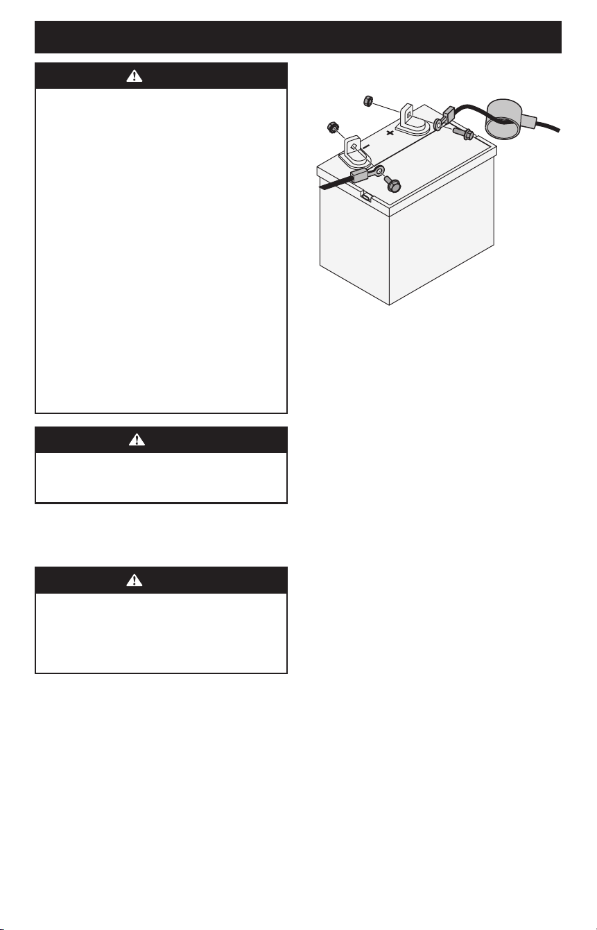
For shipping reasons the factory may leave both battery cables
disconnected from the terminals. To connect the battery cables,
proceed as follows:
1. If present, remove the plastic cover from the positive battery
terminal. Attach the red connector to the positive battery
terminal (+) using the bolt (a) and hex nut (b). See Figure 12.
2. If present, remove the plastic cover from the negative battery
terminal and attach the black cable to the negative battery
terminal (–) with the bolt (a) and hex nut (b). See Figure 12.
3. Position the red rubber boot (c) over the positive battery
terminal to help protect it from corrosion. See Figure 12.
(b)
(b)
(a)
(a)
(c)
Figure 12
NOTE: If the battery is put into service after date shown on top/
side of battery, charge the battery as instructed in the Service
and Maintenance section, prior to operating.
BATTERY MAINTENANCE
• The battery is filled with battery acid and then sealed at
the factory. However, even a “maintenance free” battery
requires some maintenance to ensure its proper life cycle.
• Spray the terminals and exposed wire with a battery
terminal sealer or coat the terminals with a thin coat of
grease or petroleum jelly, to protect against corrosion.
• Always keep the battery cables and terminals clean and free
of corrosion.
• Avoid tipping. Even a sealed battery will leak electrolyte
when tipped.
BATTERY STORAGE
• When storing the tractor for extended periods, disconnect
the negative battery cable. It is not necessary to remove
the battery.
• All batteries discharge during storage. Keep the exterior
of the battery clean, especially the top. A dirty battery will
discharge more rapidly.
• The battery must be stored with a full charge. A discharged
battery can freeze sooner than a charged battery. A fully
charged battery will store longer in cold temperatures
than hot.
• Recharge the battery before returning to service. Although
the tractor may start, the engine charging system may not
fully recharge the battery.