Network Video Recorder
User Manual

Legal Informaon
About this Document
●
This Document includes instrucons for using and managing the Product. Pictures, charts,
images and all other informaon hereinaer are for descripon and explanaon only.
●
The informaon contained in the Document is subject to change, without noce, due to
rmware updates or other reasons. Please nd the latest version of the Document at the
Hikvision website ( hps://www.hikvision.com ). Unless otherwise agreed, Hangzhou Hikvision
Digital Technology Co., Ltd. or its aliates (hereinaer referred to as "Hikvision") makes no
warranes, express or implied.
●
Please use the Document with the guidance and assistance of professionals trained in
supporng the Product.
About this Product
●
This product can only enjoy the aer-sales service support in the country or region where the
purchase is made.
●
If the product you choose is a video product, please scan the following QR code to obtain the
"Iniaves on the Use of Video Products", and read it carefully.
Acknowledgment of Intellectual Property Rights
●
Hikvision owns the copyrights and/or patents related to the technology embodied in the
Products described in this Document, which may include licenses obtained from third pares.
●
Any part of the Document, including text, pictures, graphics, etc., belongs to Hikvision. No part
of this Document may be excerpted, copied, translated, or modied in whole or in part by any
means without wrien permission.
●
and other Hikvision’s trademarks and logos are the properes of Hikvision in
various jurisdicons.
●
Other trademarks and logos menoned are the properes of their respecve owners.
●
The terms HDMI and HDMI High-Denion Mulmedia Interface, and the HDMI Logo
are trademarks or registered trademarks of HDMI Licensing Administrator, Inc. in the United
States and other countries.
Network Video Recorder User Manual
i

LEGAL DISCLAIMER
●
TO THE MAXIMUM EXTENT PERMITTED BY APPLICABLE LAW, THIS DOCUMENT AND THE
PRODUCT DESCRIBED, WITH ITS HARDWARE, SOFTWARE AND FIRMWARE, ARE PROVIDED "AS
IS" AND "WITH ALL FAULTS AND ERRORS". HIKVISION MAKES NO WARRANTIES, EXPRESS OR
IMPLIED, INCLUDING WITHOUT LIMITATION, MERCHANTABILITY, SATISFACTORY QUALITY, OR
FITNESS FOR A PARTICULAR PURPOSE. THE USE OF THE PRODUCT BY YOU IS AT YOUR OWN RISK.
IN NO EVENT WILL HIKVISION BE LIABLE TO YOU FOR ANY SPECIAL, CONSEQUENTIAL,
INCIDENTAL, OR INDIRECT DAMAGES, INCLUDING, AMONG OTHERS, DAMAGES FOR LOSS OF
BUSINESS PROFITS, BUSINESS INTERRUPTION, OR LOSS OF DATA, CORRUPTION OF SYSTEMS, OR
LOSS OF DOCUMENTATION, WHETHER BASED ON BREACH OF CONTRACT, TORT (INCLUDING
NEGLIGENCE), PRODUCT LIABILITY, OR OTHERWISE, IN CONNECTION WITH THE USE OF THE
PRODUCT, EVEN IF HIKVISION HAS BEEN ADVISED OF THE POSSIBILITY OF SUCH DAMAGES OR
LOSS.
●
YOU ACKNOWLEDGE THAT THE NATURE OF THE INTERNET PROVIDES FOR INHERENT SECURITY
RISKS, AND HIKVISION SHALL NOT TAKE ANY RESPONSIBILITIES FOR ABNORMAL OPERATION,
PRIVACY LEAKAGE OR OTHER DAMAGES RESULTING FROM CYBER-ATTACK, HACKER ATTACK,
VIRUS INFECTION, OR OTHER INTERNET SECURITY RISKS; HOWEVER, HIKVISION WILL PROVIDE
TIMELY TECHNICAL SUPPORT IF REQUIRED.
●
YOU AGREE TO USE THIS PRODUCT IN COMPLIANCE WITH ALL APPLICABLE LAWS, AND YOU ARE
SOLELY RESPONSIBLE FOR ENSURING THAT YOUR USE CONFORMS TO THE APPLICABLE LAW.
ESPECIALLY, YOU ARE RESPONSIBLE, FOR USING THIS PRODUCT IN A MANNER THAT DOES NOT
INFRINGE ON THE RIGHTS OF THIRD PARTIES, INCLUDING WITHOUT LIMITATION, RIGHTS OF
PUBLICITY, INTELLECTUAL PROPERTY RIGHTS, OR DATA PROTECTION AND OTHER PRIVACY
RIGHTS. YOU SHALL NOT USE THIS PRODUCT FOR ANY PROHIBITED END-USES, INCLUDING THE
DEVELOPMENT OR PRODUCTION OF WEAPONS OF MASS DESTRUCTION, THE DEVELOPMENT OR
PRODUCTION OF CHEMICAL OR BIOLOGICAL WEAPONS, ANY ACTIVITIES IN THE CONTEXT
RELATED TO ANY NUCLEAR EXPLOSIVE OR UNSAFE NUCLEAR FUEL-CYCLE, OR IN SUPPORT OF
HUMAN RIGHTS ABUSES.
●
IN THE EVENT OF ANY CONFLICTS BETWEEN THIS DOCUMENT AND THE APPLICABLE LAW, THE
LATTER PREVAILS.
© Hangzhou Hikvision Digital Technology Co., Ltd. All rights reserved.
Network Video Recorder User Manual
ii

Regulatory Informaon
FCC Informaon
Please take aenon that changes or modicaon not expressly approved by the party responsible
for compliance could void the user's authority to operate the equipment.
FCC compliance: This equipment has been tested and found to comply with the limits for pursuant
to part 15 of the FCC Rules. These limits are designed to provide reasonable protecon against
harmful interference in a residenal installaon. This equipment generates, uses and can radiate
radio frequency energy and, if not installed and used in accordance with the instrucons, may
cause harmful interference to radio communicaons. However, there is no guarantee that
interference will not occur in a parcular installaon. If this equipment does cause harmful
interference to radio or television recepon, which can be determined by turning the equipment
o and on, the user is encouraged to try to correct the interference by one or more of the
following measures:
●
Reorient or relocate the receiving antenna.
●
Increase the separaon between the equipment and receiver.
●
Connect the equipment into an outlet on a circuit dierent from that to which the receiver is
connected.
●
Consult the dealer or an experienced radio/TV technician for help.
FCC Condions
This device complies with part 15 of the FCC Rules. Operaon is subject to the following two
condions:
●
This device may not cause harmful interference.
●
This device must accept any interference received, including interference that may cause
undesired operaon.
EU Conformity Statement
This product and - if applicable - the supplied accessories too are marked
with "CE" and comply therefore with the applicable harmonized European
standards listed under the EMC Direcve 2014/30/EU, LVD Direcve 2014/
35/EU, the RoHS Direcve 2011/65/EU.
2012/19/EU (WEEE direcve): Products marked with this symbol cannot be
disposed of as unsorted municipal waste in the European Union. For
proper recycling, return this product to your local supplier upon the
Network Video Recorder User Manual
iii

purchase of equivalent new equipment, or dispose of it at designated
collecon points. For more informaon see: hp://www.recyclethis.info .
2006/66/EC (baery direcve): This product contains a baery that cannot
be disposed of as unsorted municipal waste in the European Union. See
the product documentaon for specic baery informaon. The baery is
marked with this symbol, which may include leering to indicate cadmium
(Cd), lead (Pb), or mercury (Hg). For proper recycling, return the baery to
your supplier or to a designated collecon point. For more informaon
see: hp://www.recyclethis.info .
Network Video Recorder User Manual
iv

Applicable Model
This manual is applicable to the following models.
Series Model
DS-7600NXI-K1 DS-7604NXI-K1
DS-7608NXI-K1
DS-7616NXI-K1
DS-7600NXI-K1/P DS-7604NXI-K1/4P
DS-7608NXI-K1/8P
DS-7600NXI-K2 DS-7608NXI-K2
DS-7616NXI-K2
DS-7632NXI-K2
DS-7600NXI-K2/P DS-7608NXI-K2/8P
DS-7616NXI-K2/16P
DS-7632NXI-K2/16P
DS-7700NXI-K4 DS-7708NXI-K4
DS-7716NXI-K4
DS-7732NXI-K4
DS-7700NXI-K4/P DS-7708NXI-K4/8P
DS-7716NXI-K4/16P
DS-7732NXI-K4/16P
Network Video Recorder User Manual
v

Symbol Convenons
The symbols that may be found in this document are dened as follows.
Symbol Descripon
Danger
Indicates a hazardous situaon which, if not avoided, will or could
result in death or serious injury.
Cauon
Indicates a potenally hazardous situaon which, if not avoided, could
result in equipment damage, data loss, performance degradaon, or
unexpected results.
Note
Provides addional informaon to emphasize or supplement
important points of the main text.
Network Video Recorder User Manual
vi

Safety Instrucon
●
Proper conguraon of all passwords and other security sengs is the responsibility of the
installer and/or end-user.
●
In the use of the product, you must be in strict compliance with the electrical safety regulaons
of the naon and region.
●
Firmly connect the plug to the power socket. Do not connect several devices to one power
adapter. Power o the device before connecng and disconnecng accessories and peripherals.
●
Shock hazard! Disconnect all power sources before maintenance.
●
The equipment must be connected to an earthed mains socket-outlet.
●
The socket-outlet shall be installed near the device and shall be easily accessible.
●
For the device with the sign indicang hazardous live, the external wiring connected to the
terminals requires installaon by an instructed person.
●
Never place the device in an unstable locaon. The device may fall, causing serious personal
injury or death.
●
Input voltage should meet the SELV (Safety Extra Low Voltage) and the LPS (Limited Power
Source) according to the IEC62368.
●
High touch current! Connect to earth before connecng to the power supply.
●
If smoke, odor or noise rise from the device, turn o the power at once and unplug the power
cable, and then please contact the service center.
●
Use the device in conjuncon with an UPS, and use factory recommended HDD if possible.
●
This equipment is not suitable for use in locaons where children are likely to be present.
●
CAUTION: Risk of explosion if the baery is replaced by an incorrect type.
●
Do not ingest baery. Chemical Burn Hazard!
●
This product contains a coin/buon cell baery. If the coin/buon cell baery is swallowed, it
can cause severe internal burns in just 2 hours and can lead to death.
●
Improper replacement of the baery with an incorrect type may defeat a safeguard (for
example, in the case of some lithium baery types).
●
Do not dispose of the baery into re or a hot oven, or mechanically crush or cut the baery,
which may result in an explosion.
●
Do not leave the baery in an extremely high temperature surrounding environment, which may
result in an explosion or the leakage of ammable liquid or gas.
●
Do not subject the baery to extremely low air pressure, which may result in an explosion or the
leakage of ammable liquid or gas.
●
Dispose of used baeries according to the instrucons.
●
Keep body parts away from fan blades and motors. Disconnect the power source during
servicing.
●
Keep body parts away from motors. Disconnect the power source during servicing.
●
Use only power supplies same with the original model, or LPS power supplies with the same
voltage and electric current.
Network Video Recorder User Manual
vii

Prevenve and Cauonary Tips
Before connecng and operang your device, please be advised of the following ps:
●
The device is designed for indoor use only. Install it in a well-venlated, dust-free environment
without liquids.
●
Ensure recorder is properly secured to a rack or shelf. Major shocks or jolts to the recorder as a
result of dropping it may cause damage to the sensive electronics within the recorder.
●
The device shall not be exposed to water dripping or splashing, and no objects lled with liquids,
such as vases, shall be placed on the device.
●
No naked ame sources, such as lighted candles, should be placed on the device.
●
The venlaon should not be impeded by covering the venlaon openings with items, such as
newspapers, table-cloths, curtains. The openings shall never be blocked by placing the device on
a bed, sofa, rug, or other similar surface.
●
For certain models, ensure correct wiring of the terminals for connecon to an AC mains supply.
●
For certain models, the equipment has been designed, when required, modied for connecon
to an IT power distribuon system.
●
idenes the baery holder itself and idenes the posioning of the cell(s) inside the
baery holder.
●
+ idenes the posive terminal(s) of the device which is used with, or generates direct current,
and - idenes the negave terminal(s) of the device which is used with, or generates direct
current.
●
If the device has been powered o or placed for a long me, its coin/buon cell baery may run
out power.
●
When the coin/buon cell baery runs out power, the system me would be incorrect, please
contact the aer-sales service to replace the baery.
●
Keep a minimum 200 mm (7.87 inch) distance around the equipment for sucient venlaon.
●
For certain models, ensure correct wiring of the terminals for connecon to an AC mains supply.
●
Do not touch the sharp edges or corners.
●
When the device is running above 45 °C (113 °F), or its HDD temperature in S.M.A.R.T. exceeds
the stated value, please ensure the device is running in a cool environment, or replace HDD(s) to
make the HDD temperature in S.M.A.R.T. below the stated value.
●
Provide a surge suppressor at the inlet opening of the device under special condions such as
the mountain top, iron tower, and forest.
●
Do not touch the bare components (such as the metal contacts of the inlets) and wait for at least
5 minutes, since electricity may sll exist aer the device is powered o.
●
The USB port of the equipment is used for connecng to a mouse, keyboard, USB ash drive, or
Wi-Fi dongle only. The current for the connected device shall be not more than 0.1 A.
●
The serial port of the device is used for debugging only.
●
If the power output port of the device does not comply with Limited Power Source, the
connected device powered by this port shall be equipped with a re enclosure.
●
If a power adapter is provided in the device package, use the provided adapter only.
Network Video Recorder User Manual
viii

●
For the device with scker or , pay aenon to the following cauons: CAUTION: Hot
parts! Do not touch. Burned ngers when handling the parts. Wait one-half hour aer switching
o before handling the parts.
●
If the device needs to be installed on the wall or ceiling,
1. Install the device according to the instrucons in this manual.
2. To prevent injury, this device must be securely aached to the installaon surface in
accordance with the installaon instrucons.
●
Under high working temperature (40 °C (104 °F) to 55 °C (131 °F)), the power of some power
adapters may decrease.
●
Make sure that the power has been disconnected before you wire, install, or disassemble the
device.
●
If the device needs to be wired by yourself, select the corresponding wire to supply power
according to the electric parameters labeled on the device. Strip o wire with a standard wire
stripper at corresponding posion. To avoid serious consequences, the length of stripped wire
shall be appropriate, and conductors shall not be exposed.
●
If smoke, odor, or noise arises from the device, immediately turn o the power, unplug the
power cable, and contact the service center.
Network Video Recorder User Manual
ix

Contents
Chapter 1 Startup ....................................................................................................................... 1
1.1 Acvate Your Device .............................................................................................................. 1
1.2 Login ...................................................................................................................................... 3
1.2.1 Log in via Unlock Paern .............................................................................................. 3
1.2.2 Log in via Password ....................................................................................................... 3
Chapter 2 Live View .................................................................................................................... 5
2.1 GUI Introducon .................................................................................................................... 5
2.2 PTZ Control ............................................................................................................................ 6
2.2.1 Congure PTZ Parameter .............................................................................................. 6
2.2.2 PTZ Control Panel Introducon ..................................................................................... 8
2.2.3 Customize Preset .......................................................................................................... 8
2.2.4 Customize Patrol ........................................................................................................... 8
2.2.5 Customize Paern ......................................................................................................... 9
Chapter 3 Playback ................................................................................................................... 10
3.1 GUI Introducon .................................................................................................................. 10
3.2 Normal Playback .................................................................................................................. 11
3.3 Event Playback ..................................................................................................................... 13
3.4 Slice Playback ....................................................................................................................... 14
3.5 Back up Clip .......................................................................................................................... 15
Chapter 4 Search File ................................................................................................................ 16
Chapter 5 Conguraon (Easy Mode) ....................................................................................... 17
5.1 System Conguraon ........................................................................................................... 17
5.1.1 General ........................................................................................................................ 17
5.1.2 User ............................................................................................................................. 17
5.1.3 Excepon .................................................................................................................... 19
5.2 Network Conguraon ........................................................................................................ 20
Network Video Recorder User Manual
x

5.2.1 General ........................................................................................................................ 20
5.2.2 Hik-Connect ................................................................................................................. 20
5.2.3 Email ........................................................................................................................... 22
5.3 Camera Management .......................................................................................................... 23
5.3.1 Network Camera ......................................................................................................... 23
5.3.2 OSD Sengs ................................................................................................................ 26
5.3.3 Moon ........................................................................................................................ 27
5.4 Device Access ....................................................................................................................... 30
5.4.1 Switch .......................................................................................................................... 30
5.4.2 Non-Video Event (Easy Mode) .................................................................................... 31
5.4.3 IP Speaker ................................................................................................................... 31
5.5 PoE Sengs .......................................................................................................................... 33
5.5.1 Congure PoE Power ................................................................................................... 33
5.5.2 Congure PoE Binding ................................................................................................. 34
5.6 Recording Management ....................................................................................................... 34
5.6.1 Storage Device ............................................................................................................ 34
5.6.2 Congure Recording Schedule .................................................................................... 35
5.6.3 Congure Recording Parameter .................................................................................. 37
Chapter 6 Conguraon (Expert Mode) .................................................................................... 39
6.1 System Conguraon ........................................................................................................... 39
6.1.1 General ........................................................................................................................ 39
6.1.2 Live View ..................................................................................................................... 40
6.1.3 User ............................................................................................................................. 42
6.2 Network Conguraon ........................................................................................................ 42
6.2.1 TCP/IP .......................................................................................................................... 42
6.2.2 DDNS ........................................................................................................................... 43
6.2.3 NAT .............................................................................................................................. 44
6.2.4 NTP .............................................................................................................................. 45
Network Video Recorder User Manual
xi

6.2.5 Upload Logs to the Server ........................................................................................... 46
6.2.6 Ports (More Sengs) .................................................................................................. 46
6.2.7 Hik-Connect ................................................................................................................. 48
6.2.8 ISUP ............................................................................................................................. 48
6.2.9 OTAP Service ............................................................................................................... 49
6.2.10 Email ......................................................................................................................... 50
6.3 Camera Management .......................................................................................................... 50
6.3.1 Network Camera ......................................................................................................... 50
6.3.2 Display Sengs ........................................................................................................... 57
6.3.3 Privacy Mask ............................................................................................................... 58
6.4 Device Access ....................................................................................................................... 59
6.4.1 Switch .......................................................................................................................... 59
6.4.2 IP Speaker ................................................................................................................... 60
6.5 PoE Sengs .......................................................................................................................... 62
6.5.1 Congure PoE Power ................................................................................................... 62
6.5.2 Congure PoE Binding ................................................................................................. 63
6.6 Event Conguraon ............................................................................................................. 63
6.6.1 Normal Event .............................................................................................................. 63
6.6.2 Perimeter Protecon ................................................................................................... 68
6.6.3 Facial Recognion ....................................................................................................... 72
6.6.4 Non-Video Event ......................................................................................................... 74
6.6.5 Other Events ............................................................................................................... 75
6.6.6 Congure Arming Schedule ........................................................................................ 75
6.6.7 Congure Alarm Linkage Acon .................................................................................. 76
6.7 Intelligent Search ................................................................................................................. 78
6.7.1 AcuSearch ................................................................................................................... 78
6.8 Recording Management ....................................................................................................... 79
6.8.1 Congure Recording Schedule .................................................................................... 79
Network Video Recorder User Manual
xii

6.8.2 Congure Recording Parameter .................................................................................. 81
6.8.3 Storage Device ............................................................................................................ 82
6.8.4 Congure Storage Mode ............................................................................................. 84
6.8.5 Advanced Sengs ....................................................................................................... 84
6.9 Face Picture Library Management ....................................................................................... 85
6.9.1 Add a Face Picture Library ........................................................................................... 85
6.9.2 Upload Face Pictures to the Library ............................................................................ 85
Chapter 7 Maintenance ............................................................................................................ 87
7.1 Restore Default .................................................................................................................... 87
7.2 Search Log ............................................................................................................................ 87
7.3 System Service ..................................................................................................................... 87
7.4 Buzzer Switch ....................................................................................................................... 88
7.5 Device Maintenance ............................................................................................................ 89
7.5.1 Schedule Reboot ......................................................................................................... 89
7.5.2 Camera Upgrade ......................................................................................................... 89
7.5.3 Device Status ............................................................................................................... 89
7.5.4 Time Sync Diagnosis .................................................................................................... 89
7.5.5 Picture Buer Enhancement ....................................................................................... 90
7.6 Upgrade ............................................................................................................................... 90
7.6.1 Local Upgrade ............................................................................................................. 91
7.6.2 Online Upgrade ........................................................................................................... 91
Chapter 8 Alarm ....................................................................................................................... 92
8.1 Set Event Hint ....................................................................................................................... 92
8.2 View Alarm in Alarm Center ................................................................................................. 92
Chapter 9 Web Operaon ......................................................................................................... 93
9.1 Introducon ......................................................................................................................... 93
9.2 Login .................................................................................................................................... 93
9.3 Live View .............................................................................................................................. 94
Network Video Recorder User Manual
xiii

9.4 Playback ............................................................................................................................... 94
9.5 Conguraon ....................................................................................................................... 95
9.6 Log ....................................................................................................................................... 96
Chapter 10 Appendix ................................................................................................................ 97
10.1 Glossary ............................................................................................................................. 97
Network Video Recorder User Manual
xiv
Chapter 1 Startup
1.1 Acvate Your Device
For the rst-me access, you need to acvate the video recorder by seng an admin password. No
operaon is allowed before acvaon. You can also acvate the video recorder via web browser,
SADP or client soware.
Before You Start
Power on your device.
Steps
1.
Select a language.
2.
Click Apply.
3.
Set the resoluon as 1920*1080/60Hz (1080P) as needed.
Note
●
The resoluon is 1280*720/60Hz (720P) by default. If you check Do not show this prompt
again., the prompt will not appear again aer reboong.
●
Aer the device is connected to the monitor with HDMI cable, the resoluon will be
automacally adjusted to 1920*1080/60Hz (1080P). Some monitor models do not support
resoluon adaptaon.
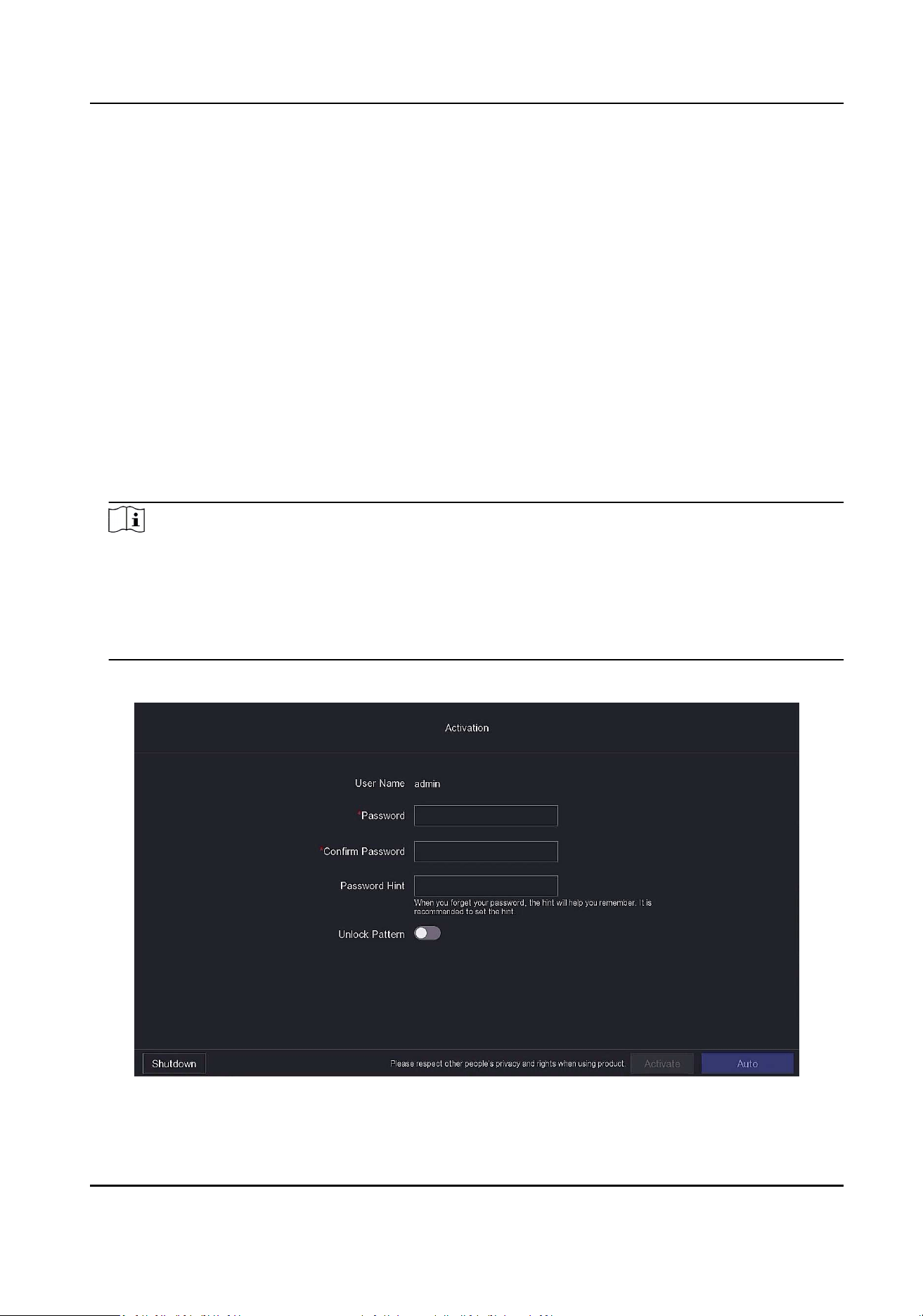
4.
Input the same password in Password and Conrm Password.
Figure 1-1 Acvaon
Network Video Recorder User Manual
1

Warning
●
Strong Password recommended-We highly recommend you create a strong password of your
own choosing according to the following rules in order to increase the security of your
product:
○
8 to 16 characters.
○
Do not contain the following characters in the password: the user name, 123, admin, no less
than 4-digit connuously increasing or decreasing numbers, or no less than 4 connuously
same characters.
○
Ar least 2 of the following types are required: digits, upper-case leers, lower-case leers,
and special characters.
○
Risky password is not allowed.
●
We recommend you reset your password regularly, especially in the high security system,
reseng the password monthly or weekly can beer protect your product.
5.
Oponal: Set Password Hint.
Note
When you forget your password, the hint will help you remember it. It is recommended to set
the password hint.
6.
Oponal: Set Unlock Paern.
1) Enable Unlock Paern.
2) Use the mouse to draw a paern among the 9 dots on the screen. Release the mouse when
the paern is done.
Note
●
The paern shall have 4 dots at least.
●
Each dot can be connected for once only.
3) Draw the same paern again to conrm it. When the two paerns match, the paern is
congured successfully.
7.
Click Acvate.
What to do next
Follow the wizard to set basic parameters.
●
For basic system parameters. Refer to
General for details.
●
For general network parameters. Refer to General for details.
●
For storage device conguraon. Refer to Storage Device for details.
●
For adding network cameras. Refer to Network Camera for details.
●
For plaorm conguraon. Refer Hik-Connect to for details.
●
When you forget your password, there are three methods to reset it, including password
reseng email, Hik-Connect, and security quesons. You have to congure at least one
password reseng method. Refer to Set Password Reseng Email and Hik-Connect for details.
Network Video Recorder User Manual
2
1.2 Login
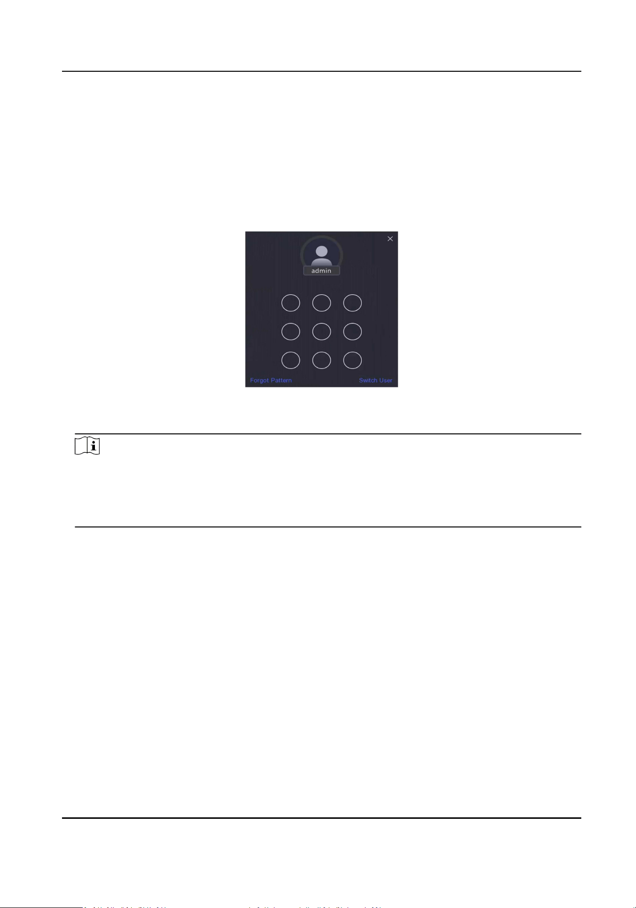
1.2.1 Log in via Unlock Paern
Steps
1.
Right click the mouse on live view.
Figure 1-2 Draw the Unlock Paern
2.
Draw the pre-dened paern to enter the menu operaon.
Note
●
If you have forgoen your paern, you click Forgot My Paern or Switch User to log in via
password.
●
If you have drawn the wrong paern for more than 5 mes, the system will switch to the
normal login mode automacally.
1.2.2 Log in via Password
If your video recorder has logged out, you must login before operang the menu and other
funcons.
Steps
1.
Select User Name.
Network Video Recorder User Manual
3

Figure 1-3 Login Interface
2.
Input password.
3.
Click Login.
Note
●
When you forget the password of the admin, you can click Forgot Password to reset the
password.
●
If you enter the wrong password 7 mes, the current user account will be locked for 60
seconds.
Network Video Recorder User Manual
4
Chapter 2 Live View
2.1 GUI Introducon
●
Click Target Detecon at the upper-le corner, and select or to display the specied live
target detecon results. For result details, click View More.
Note
○
Target Detecon is only available for certain models.
○
Target Detecon is valid when HDD is installed.
○
is valid for moon detecon, line crossing detecon, intrusion detecon, and facial
detecon.
●
Click , check the IP speaker, and click Start to start broadcast.
Note
Before start broadcast, you need to refer to IP Speaker to add the IP speaker.
●
Click to enable/disable self-adapve resoluon. Aer enabling this funcon, the image
display eect would be adjusted according to the screen size.
●
Click
to start/stop auto-switch. The screen will automacally switch to the next one.
●
Click to enter full screen mode.
●
Double click a camera to view it in single-screen mode. Double click again to exit single-screen
mode.
●
Change a camera live view screen by dragging it from its screen to the desired screen.
●
Scroll up/down to turn to previous/next screen.
●
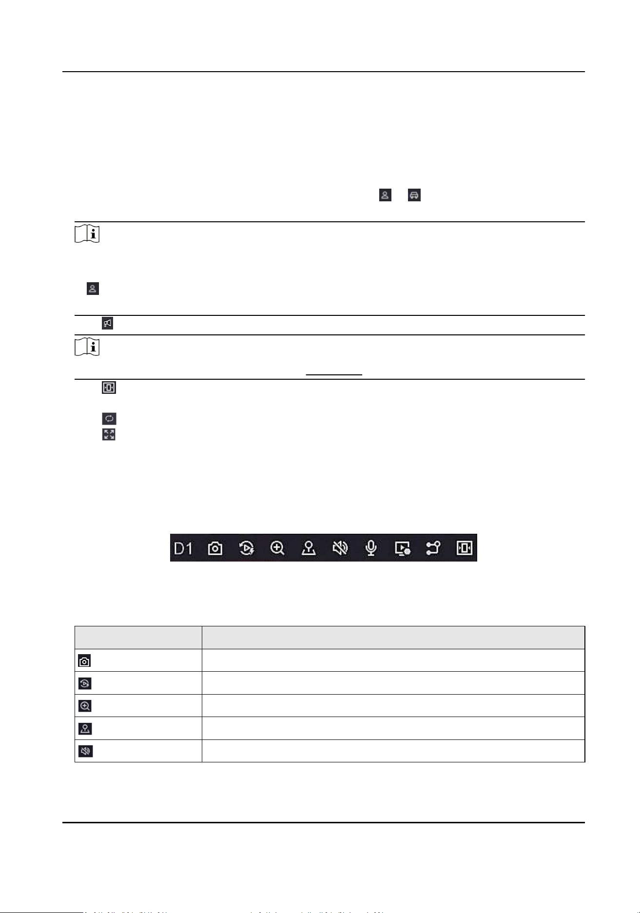
Posion the cursor on a camera to show shortcut menu.
Figure 2-1 Shortcut Menu
Table 2-1 Shortcut Menu Descripon
Buon Descripon
Click to capture.
Start playing videos recorded in the latest ve minutes.
Digital zoom. You can adjust zoom-in mes and view the desired area.
Click it to enter PTZ control mode.
Turn on/o live view audio.
Network Video Recorder User Manual
5
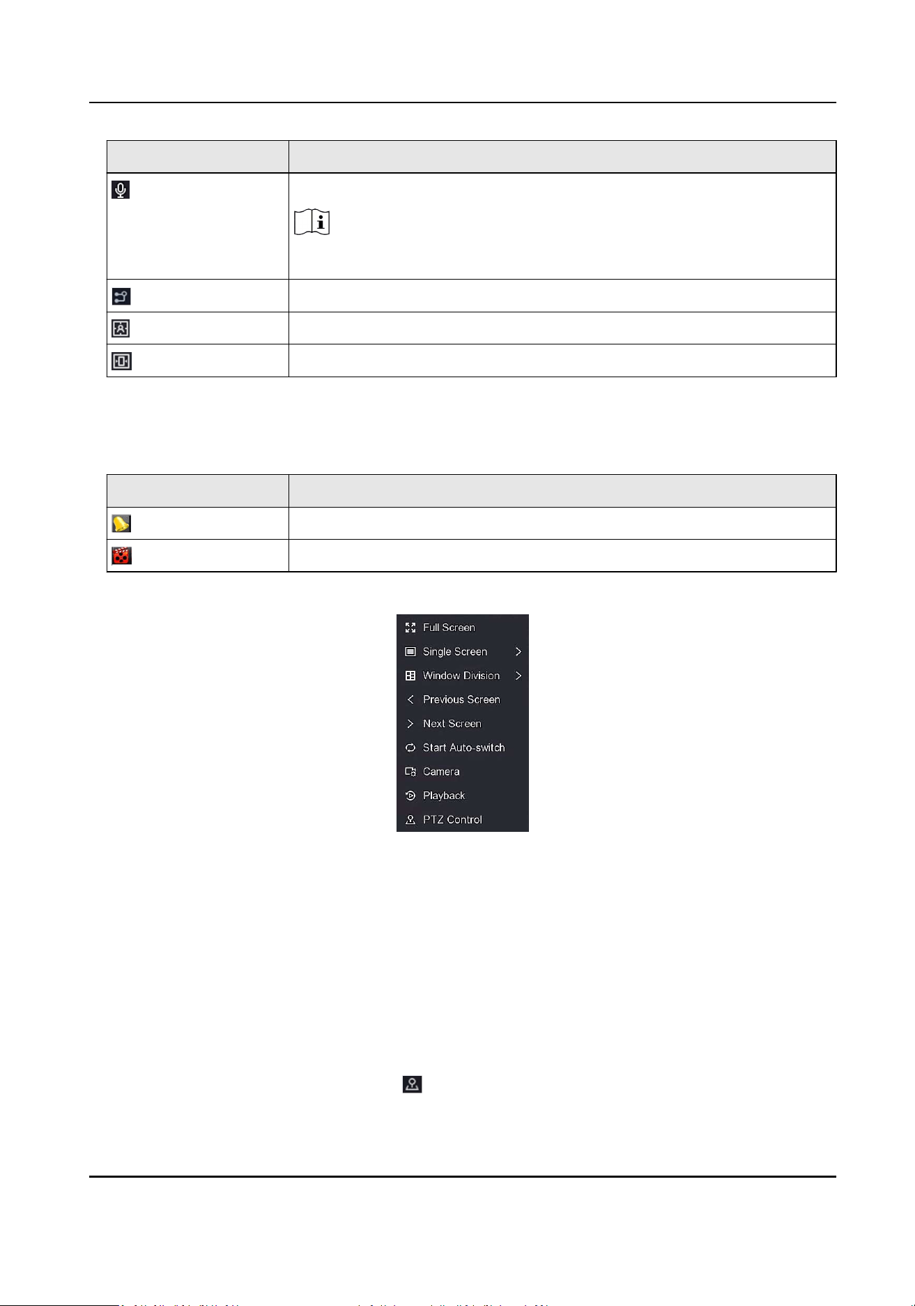
Buon Descripon
Click to start two-way audio between NVR and network camera.
Note
Ensure that the network camera supports two-way audio.
Switch video stream.
Display rule frame and target frame.
Adjust image display eect according to the screen size.
●
In the live view interface, there are icons at the upper-right corner of the screen for each
camera, showing the camera recording and alarm status.
Table 2-2 Live View Icon Descripon
Icon Descripon
Alarming (normal event and smart event).
Recording.
●
Right click your mouse to display the shortcut menu.
Figure 2-2 Right Click Shortcut Menu
2.2 PTZ Control
2.2.1 Congure PTZ Parameter
You shall congure PTZ parameters before controlling a PTZ camera.
Steps
1.
Preview a camera in live view and click on shortcut menu.
Network Video Recorder User Manual
6
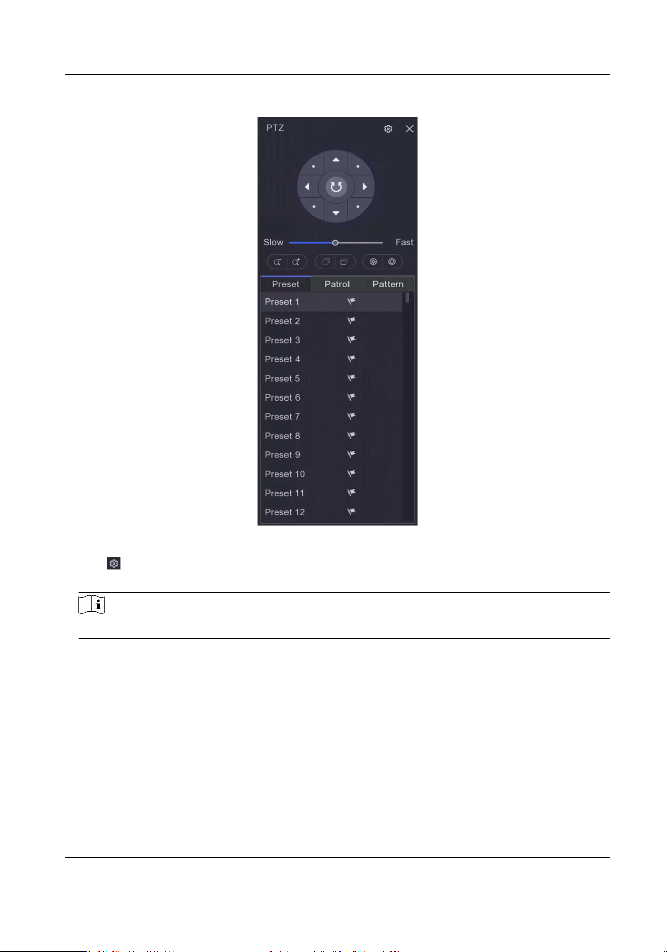
Figure 2-3 PTZ Sengs
2.
Click .
3.
Set the PTZ camera parameters.
Note
All parameters should be the same as the PTZ camera.
4.
Click OK.
Network Video Recorder User Manual
7
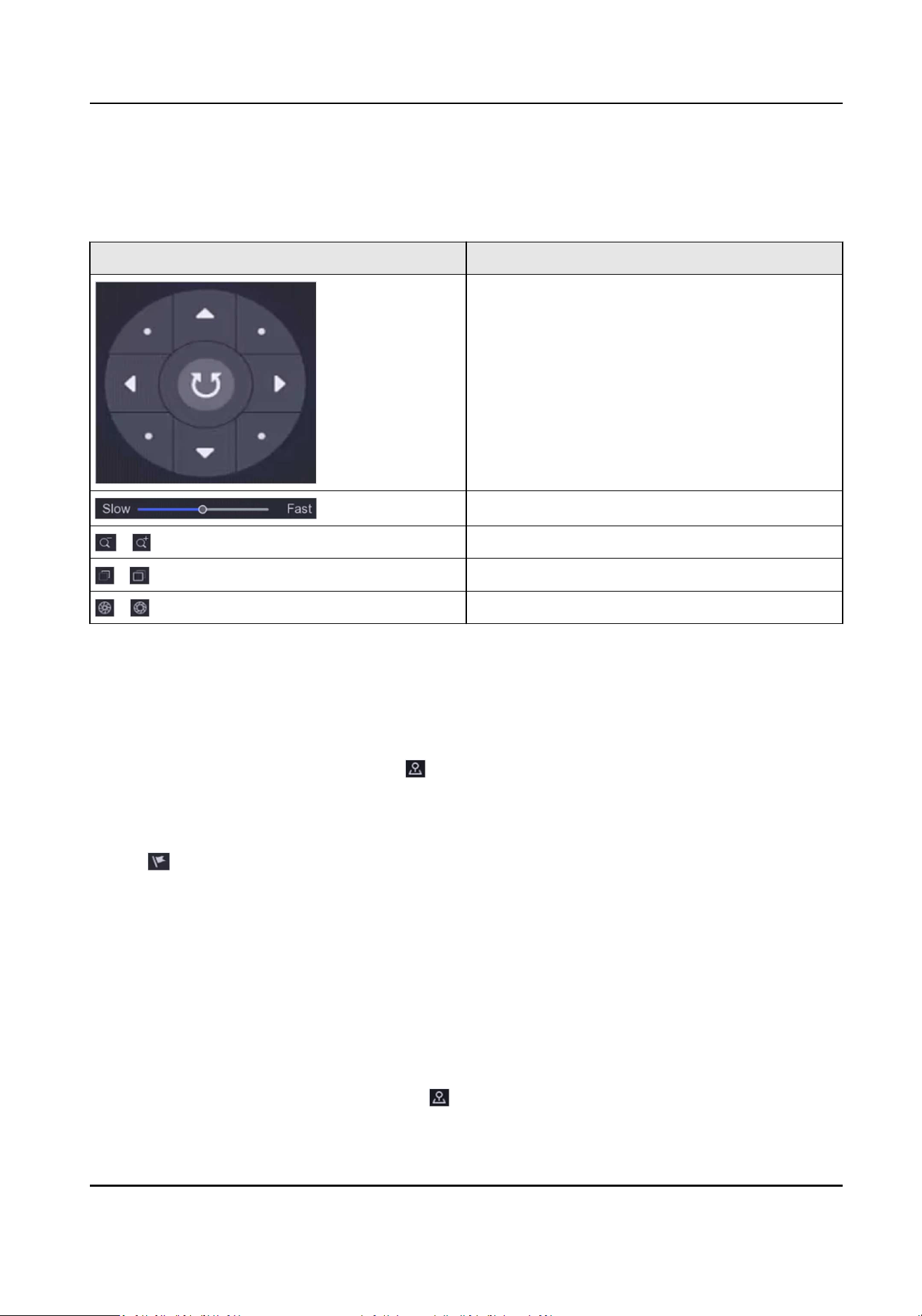
2.2.2 PTZ Control Panel Introducon
Table 2-3 PTZ Panel Descripon
Icon Descripon
Direcon buons, and the auto-cycle buon.
The speed of the PTZ movement.
/ Zoom -/+.
/ Focus -/+.
/ Iris -/+.
2.2.3 Customize Preset
Set a preset locaon where the PTZ camera would point to when an event occurs.
Steps
1.
Preview a camera in live view and click on shortcut menu.
2.
Select a desired preset in preset list.
3.
Use direcon buons to wheel the camera to required locaons. Adjust zoom and focus as your
desire.
4.
Click .
What to do next
Double click a preset in the preset list to call it.
2.2.4 Customize Patrol
Patrol refers to a path consists of a series of presets with designated sequence. It provides dynamic
live image for monitoring several presets.
Steps
1.
Preview a camera in live view and click on
shortcut menu.
Network Video Recorder User Manual
8

2.
Click Patrol.
3.
Click of a desired patrol.
4.
Click .
5.
Congure key point parameters, such as the key point No., duraon of staying for one key point
and speed of patrol. The key point is corresponding to the preset. The preset number
determines the order at which the PTZ will follow while cycling through the patrol. Duraon
refers to the me span to stay at the corresponding key point. Speed denes the speed at which
the PTZ will move from one key point to the next.
Figure 2-4 Patrol Sengs
6.
Click OK.
7.
Click Save.
What to do next
Select a patrol and click to call it. The PTZ camera will move according the predened patrol
path.
2.2.5 Customize Paern
A paern records the movement path and dwell me in a certain posion. When you call a
paern, the PTZ camera will move according to the recorded path.
Steps
1.
Preview a camera in live view and click on shortcut menu.
2.
Click Paern.
3.
Select a paern.
4.
Click
.
5.
Use direcon buons to wheel the camera to required locaons. Adjust zoom and focus as your
desire.
6.
Click . The previous PTZ camera moving path is recorded as a paern.
What to do next
Select a paern and click to call it. The PTZ camera will move according the predened paern.
Network Video Recorder User Manual
9
Chapter 3 Playback
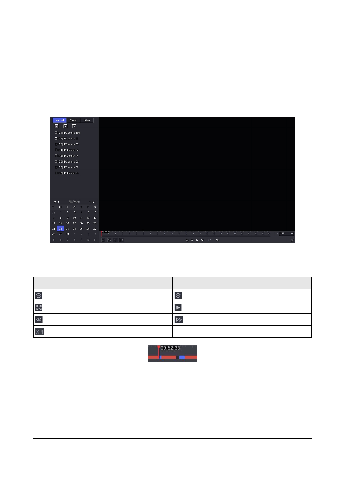
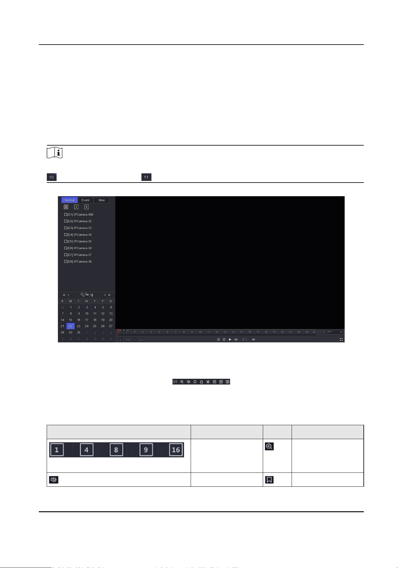
3.1 GUI Introducon
Go to Playback .
Figure 3-1 Playback
Table 3-1 Playback Interface Descripon
Buon Operaon Buon Operaon
30 s reverse. 30 s forward.
Full screen. Start playback.
Speed down. Speed up.
Speed.
Figure 3-2 Timeline
●
Posion the cursor on the meline, drag the meline to posion to a certain me.
●
Period marked with blue bar contains video. Red bar indicates the video in the period is event
video.
●
Scroll up/down to zoom out/in meline.
Network Video Recorder User Manual
10
3.2 Normal Playback
Play back normal videos.
Steps
1.
Go to Playback .
2.
Select a camera from the camera list.
3.
Select a date on the calendar for playback.
Note
The blue triangle at the calendar date corner indicates there are available videos. For example,
means video is available. means no video.
Figure 3-3 Playback
4.
Oponal: Posion the cursor on playback window to show control bar.
Figure 3-4 Control Bar
Table 3-2 Buon Descripon
Buon Descripon Buon Descripon
Window division,
group the channels
and play.
Zoom in/out
playback image.
Turn on/o audio. Add tag.
Network Video Recorder User Manual
11

Buon Descripon Buon Descripon
Lock/unlock video. Clip video.
Show videos that
contain human.
Show videos that
contain vehicle.
Skip Normal Videos If you have clicked
/ , the device
will hide other
videos, and only
show and play
videos that contain
human or vehicle
during playback.
Display rule frame
and target frame.
Adjust image display
eect according to
the screen size.
Smart
Search
( )
If you have clicked
/ , you can
click and
congure the
detecon area to
quickly search the
human/vehicle
informaon in this
area.
a. Aer clicking the
buon, targets
will be displayed
on the screen.
b. Click a target to
search for
pictures that
contain the
target.
c. Click a picture to
play a video
before and aer
that moment.
Note
Before using this
funcon, you need
to enable
Mul-window
division playback.
Network Video Recorder User Manual
12
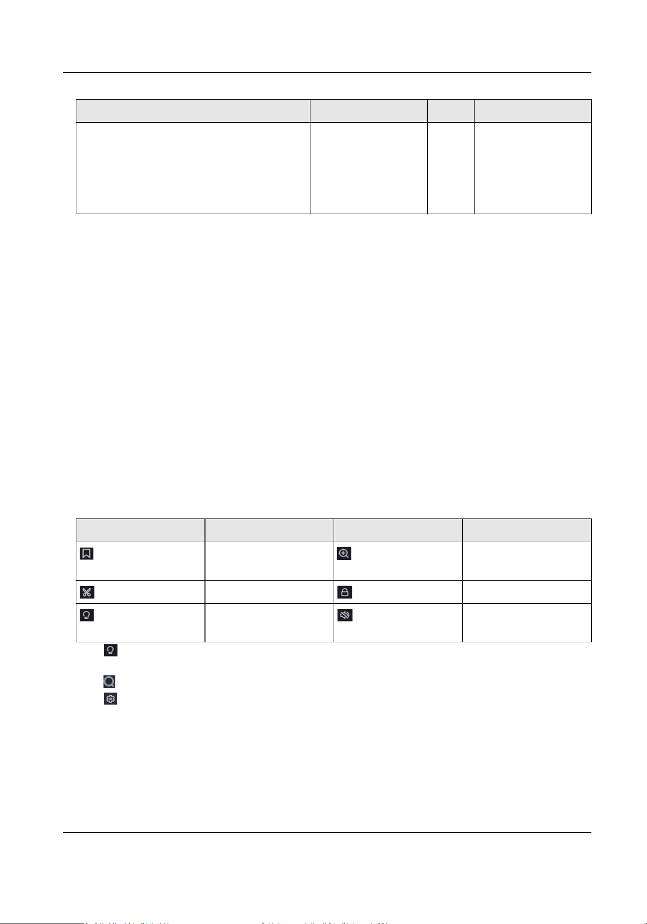
Buon Descripon Buon Descripon
AcuSearch
algorithm for the
current channel.
Please refer to
AcuSearch .
3.3 Event Playback
When you select the event playback mode, the system will analyze and mark videos that contain
the moon detecon, line crossing detecon, or intrusion detecon informaon, .
Before You Start
●
Ensure the camera has enabled Dual-VCA. You can enable it via the camera web browser
interface in Conguraon → Video/Audio → Display Info. on Stream .
●
Ensure your video recorder has enabled Save VCA Data. You can enable it in Conguraon →
Record → Advanced .
Steps
1.
Go to Playback .
2.
Click Event.
3.
Select a camera.
4.
Posion the cursor on playback window to show control bar.
Table 3-3 Buon Descripon
Buon Descripon Buon Descripon
Add tag. Zoom in/out playback
image.
Clip video. Lock/unlock video.
Congure detecon
area.
Turn on/o audio.
5.
Click to set detecon areas of line crossing detecon, intrusion detecon, or moon
detecon.
6.
Click to search videos. Videos meet the detecon rule requirement will be marked in red.
7.
Click to congure the play strategy.
Skip Normal Videos
If it is enabled, videos without smart informaon will not be played.
Normal Video
Network Video Recorder User Manual
13
Set normal video playback speed. The opon is only valid when Do not Play Normal Videos is
unchecked.
Play Speed of Smart/Custom Video
Set playback speed of videos with smart informaon. The opon is only valid when Do not
Play Normal Videos is enabled.
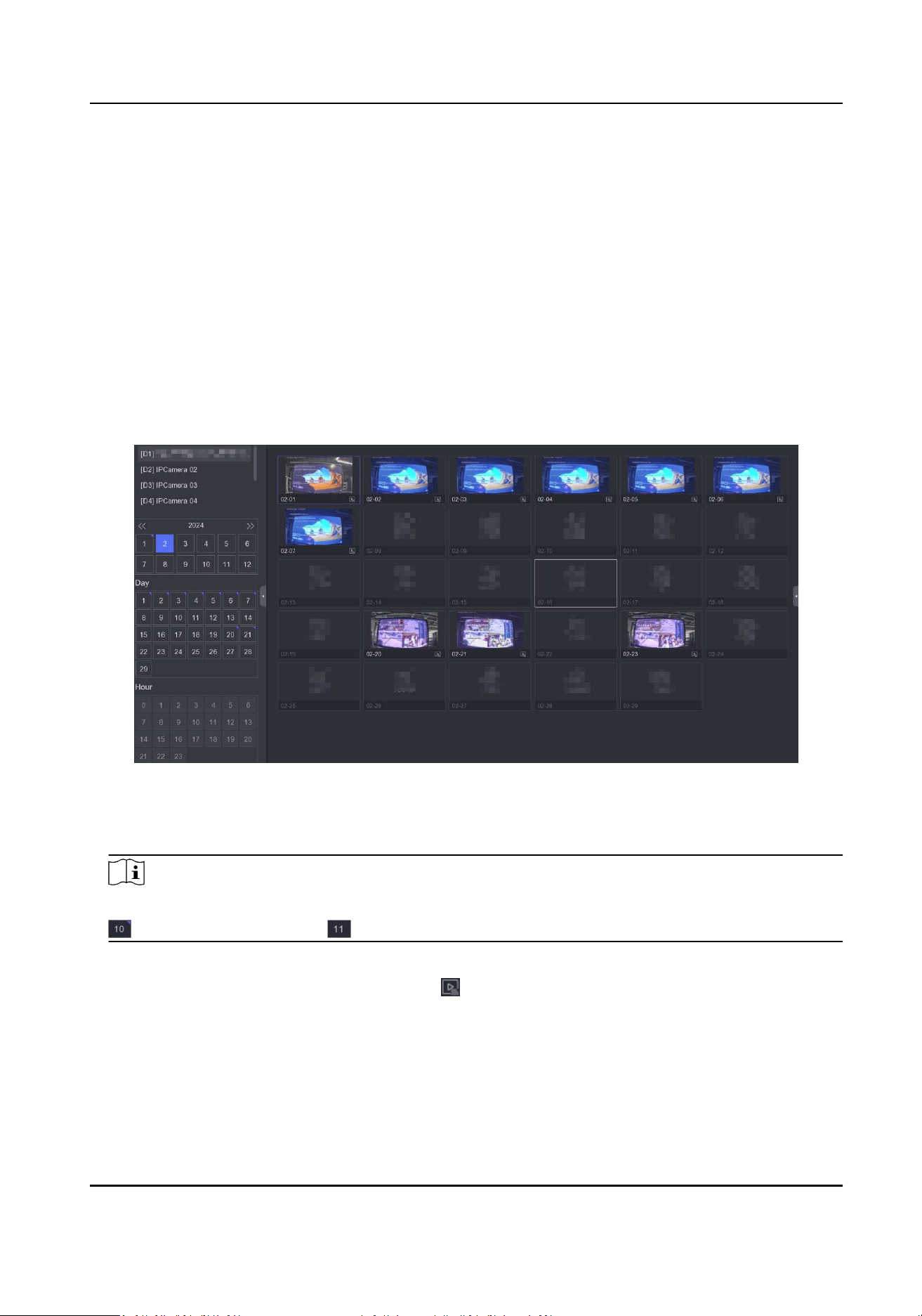
3.4 Slice Playback
Divide the video into slices and play them back.
Steps
1.
Go to Playback → Slice Playback .
Figure 3-5 Slice Playback
2.
Select a camera from the camera list.
3.
Select a month, a date, and an hour on the calendar for playback.
Note
The blue triangle at the calendar date corner indicates there are available videos. For example,
means video is available. means no video.
The retrieved video will be divided into one-hour slices for playback.
4.
Oponal: Select an one-hour slice and click to divide it into one-minute slices for playback.
5.
Click a slice to play back the video on the right.
Network Video Recorder User Manual
14
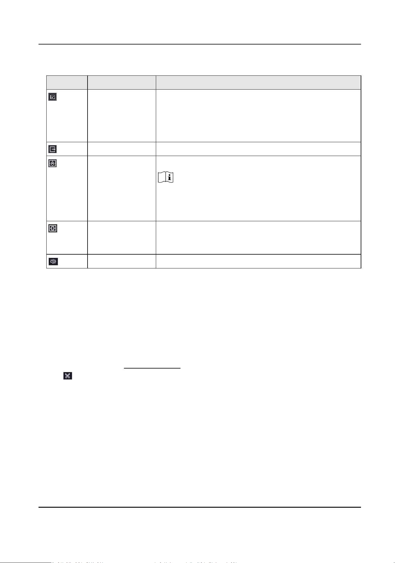
Table 3-4 Slice Playback Icon Descripon
Icon Name Descripon
AcuSearch a. Aer clicking the buon, targets will be displayed on the
screen.
b. Click a target to search for pictures that contain the target.
c. Click a picture to play a video before and aer that
moment.
Export Video Click to export the video.
Display VCA Info Display rule frame and target frame.
Note
Prerequisite: The channel has been added and can be
previewed. VCA conguraon has been completed on the
camera or device.
Enable Self-
Adapve
Resoluon
Adjust the image display eect according to the screen size.
Audio Control Turn on/o audio and adjust the volume.
3.5 Back up Clip
You can clip videos during playback. Video clips can be exported to the backup device (USB ash
drive, etc.).
Before You Start
Connect a backup device to your video recorder.
Steps
1.
Start playback. Refer to Normal Playback for details.
2.
Click .
3.
Set the start and end me.
4.
Click Save.
5.
Select the backup device and folder.
6.
Click Save to export the clip to backup device.
Network Video Recorder User Manual
15

Chapter 4 Search File
Steps
1.
Go to Search.
2.
Select a search type (video, picture, event, etc.).
3.
Set search condions.
4.
Oponal: Click Quick Backup to quickly export videos to the device.
Note
Quick backup is available for video and event search.
5.
Click Search.
-
Click
to play the video.
-
Click
to lock the le. Locked le will not be overwrien.
-
Select le(s), and click Export to export le(s) to backup device.
Network Video Recorder User Manual
16

Chapter 5 Conguraon (Easy Mode)
Easy mode contains basic conguraons. Go to Conguraon , and click Easy Mode.
5.1 System Conguraon
5.1.1 General
You can congure the output resoluon, system me, etc.
Steps
1.
Go to Conguraon → System → General .
2.
Congure the parameters as your desire.
Local Auto Login
Aer Local Auto Login is enabled, the device password will no longer be veried unl the
admin user logs out. Please take good care of your device and admin password to prevent
losses.
Wizard
The wizard will pop up aer the device starts up.
NTP Time Sync
Network me protocol (NTP) is a networking protocol for me synchronizaon. The device
can connect to NTP (network me protocol) server to sync me.
Interval (min)
Time interval between two me synchronizaon with NTP server.
NTP Server
IP address of the NTP server.
3.
Click Apply.
5.1.2 User
Add User
There is a default account: Administrator. The administrator user name is admin. Administrator has
the permission to add, delete, and edit user. Guest user only has live view, playback, and log search
permission.
Network Video Recorder User Manual
17

Steps
1.
Go to Conguraon → System → User .
2.
Click Add and conrm your admin password.
3.
Enter user name.
4.
Select user level.
5.
Enter the same password in Create Password and Conrm.
Warning
●
We highly recommend you create a strong password of your own choosing in order to
increase the security of your product.
○
8 to 16 characters.
○
Do not contain following characters in the password: the user name, 123, admin, no less
than 4-digit connuously increasing or decreasing numbers, or no less than 4 connuously
same characters.
○
At least 2 of the following types are required: digits, upper-case leers, lower-case leers,
and special characters.
○
Risky password is not allowed.
●
We recommend you reset your password regularly, especially in the high security system,
reseng the password monthly or weekly can beer protect your product.
6.
Congure user permissions.
7.
Click OK.
-
Click
/ to edit/delete user.
Set Password Reseng Email
When you forgot your login paern and password, the device will send an email contains
vericaon code to your email for password reseng.
Steps
1.
Go to Conguraon → User .
2.
Click Password Reseng Email.
3.
Enter admin password for authorizaon.
4.
Enter an email address.
5.
Click OK.
Reset Password
You can reset your password when you forgot your login paern and password.
Steps
1.
Click Forgot Password at the password login interface.
2.
Click Next if you agree the Privacy Policy, you can scan the QR code to read it.
Network Video Recorder User Manual
18
3.
Follow the wizard to reset password.
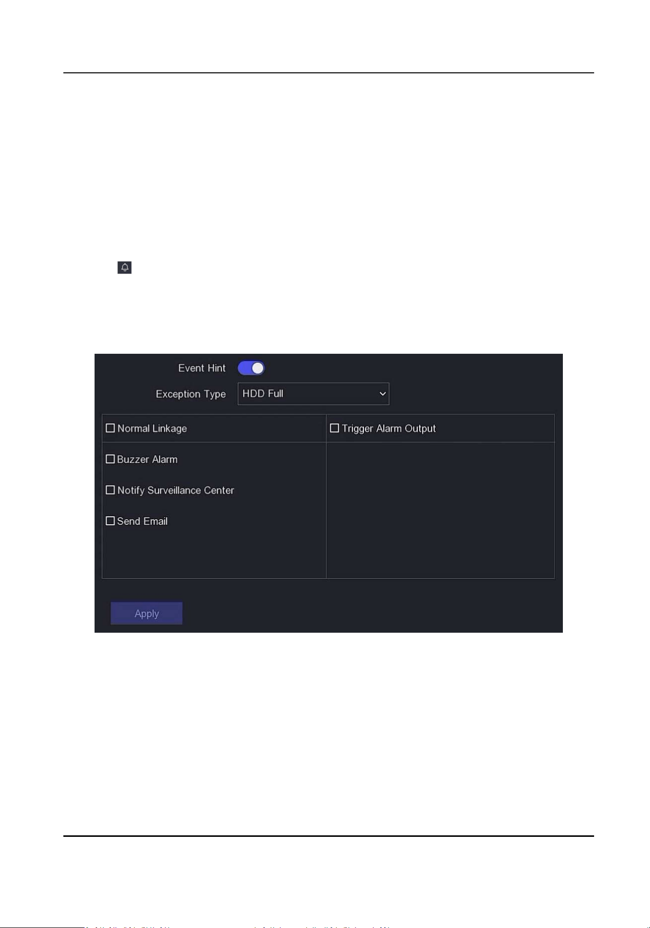
5.1.3 Excepon
You can receive excepon events hint in alarm center, and set excepon linkage acons.
Steps
1.
Go to Conguraon → System → Excepon .
2.
Oponal: Congure event hint. When the set events occur, you will receive hints in alarm center.
1) Enable Event Hint.
2) Click at the upper-right corner of local menu to enter alarm center.
3) Select an event type.
4) Click Set to select events to hint.
3.
Set Excepon Type
4.
Select Normal Linkage type for excepon linkage acons.
Figure 5-1 Excepon
5.
Click Apply.
Network Video Recorder User Manual
19
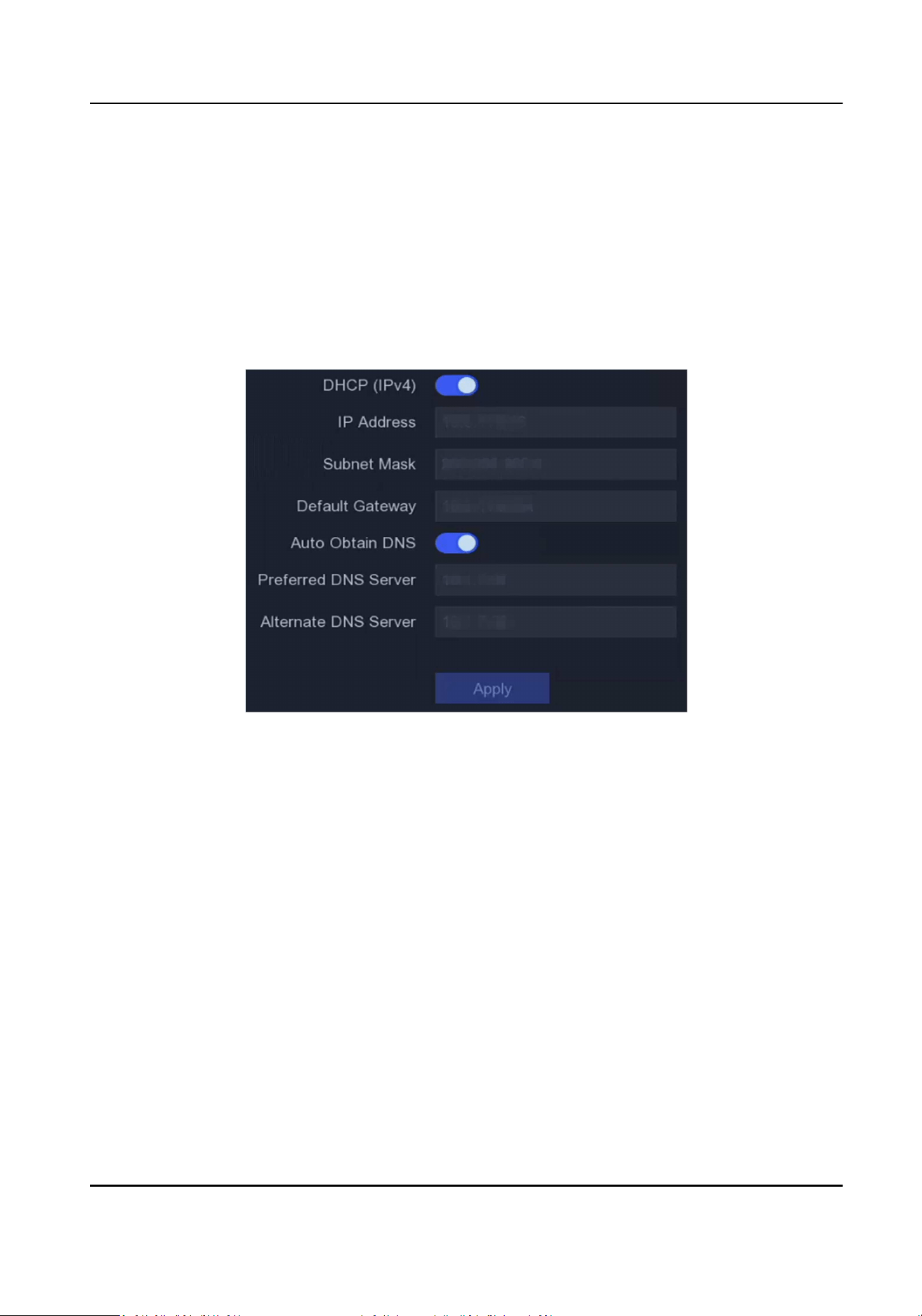
5.2 Network Conguraon
5.2.1 General
You shall properly congure the network sengs before operang the device over network.
Steps
1.
Go to Conguraon → Network → General .
Figure 5-2 Network
2.
Set network parameters.
DHCP
If the DHCP server is available, you can enable DHCP to automacally obtain an IP address
and other network sengs from that server.
Auto Obtain DNS
If DHCP is enabled. You can enable Auto Obtain DNS to automacally obtain Preferred DNS
Server and Alternate DNS Server.
3.
Click Apply.
5.2.2 Hik-Connect
Hik-Connect provides mobile phone applicaon and plaorm service to access and manage your
connected devices, which enables you to get a convenient remote access to the video security
system.
Network Video Recorder User Manual
20

Steps
1.
Go to Conguraon → Network → Hik-Connect .
2.
Turn on Enable. The service terms will pop up.
1) Read the service terms and privacy statement.
2) Check I have read and agree to Service Terms and Privacy Statement. if you agree with the
service terms and privacy statement..
3) Click OK.
3.
Click to set vericaon code.
4.
Oponal: Enable Plaorm Time Sync, the device will sync me with the plaorm server instead
of NTP server.
5.
Oponal: Enable Stream Encrypon. It requires to enter vericaon code in remote access and
live view aer this funcon is enabled.
6.
Oponal: Edit Server IP.
7.
Oponal: Enable Sub-Stream Self-Adapve Bitrate. When the network environment is poor, the
device would automacally adjust video bitrate to ensure playing uency.
8.
Bind your device with a Hik-Connect account.
1) Use a smart phone to scan the QR code, and download Hik-Connect app. You can also
download it from hps://appstore.hikvision.com , or the QR code below. Refer to Hik-
Connect Mobile Client User Manual for details.
Figure 5-3 Download Hik-Connect
2) Use Hik-Connect to scan the device QR, and bind the device.
Note
●
If the device is already bound with an account, you can click Unbind to unbind with the
current account.
●
You can also use the QR code in at the upper-le corner to download Hik-Connect and
bind your device.
9.
Click Apply.
Network Video Recorder User Manual
21
Result
●
If your device is connected with Hik-Connect plaorm, Connecon Status will be Online.
●
If your device is bound with a Hik-Connect account, Bind Status will be Yes.
What to do next
You can access your video recorder via Hik-Connect.
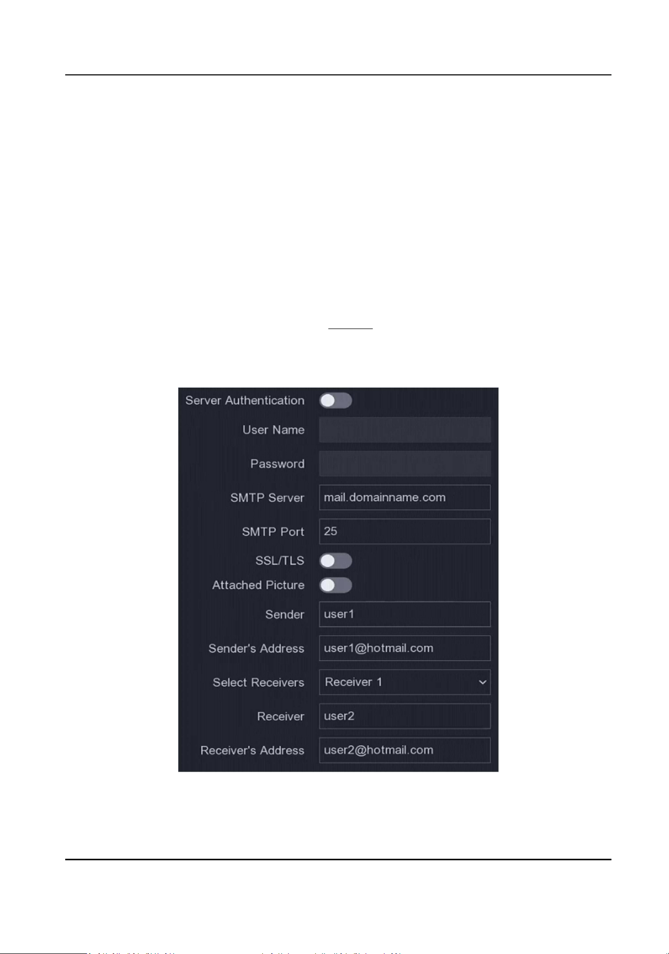
5.2.3 Email
Set an email account to receive event nocaon.
Before You Start
●
Ensure SMTP service is available for your email.
●
Congure your network parameters. Refer to General for details.
Steps
1.
Go to Conguraon → Network → Email .
Figure 5-4 Email
Network Video Recorder User Manual
22

2.
Set email parameters
Server Authencaon
Check it to enable the server authencaon feature.
User Name
The user account of email sender for SMTP server authencaon.
Password
The password of email sender for SMTP server authencaon.
SSL/TLS
(Oponal) Enable SSL/TLS if it is required by the SMTP server.
Aached Picture
(Oponal) If events are triggered, it will send images as email aachment.
Sender
The sender name.
Sender's Address
The sender's email address.
Select Receiver
Select a receiver. Up to 3 receivers are available.
Receiver
The receiver name.
Receiver's Address
The receiver's email address.
Note
For network cameras, the event images are directly sent as the email aachment. One network
camera only sends one picture.
3.
Oponal: Click Test to send a test email.
4.
Click Apply.
5.3 Camera Management
5.3.1 Network Camera
Add Network Camera by Device Password
Add network cameras which the password is the same as your video recorder.
Network Video Recorder User Manual
23

Before You Start
●
Ensure your network camera is on the same network segment with your video recorder.
●
Ensure the network connecon is valid and correct. Refer to General for details.
●
Ensure the network camera password is the same as your video recorder.
Steps
1.
Go to Conguraon → Camera → IP Camera . The online cameras on the same network
segment with your video recorder are displayed in Online Device List.
2.
Select a desired network camera.
3.
Click to add the camera.
Note
If the camera is inacve, the device will acvate it automacally with the password you have set
during device acvaon.
4.
Oponal: If your network camera is not on the same network segment with the NVR and
supports ONVIF protocol, click Advanced Search and ll in the rst three octets of the camera IP
address to add the camera(s).
Add Network Camera Manually
Before You Start
●
Ensure your network camera is on the same network segment with that of your video recorder.
●
Ensure the network connecon is valid and correct.
●
Ensure the network camera is acvated.
Steps
1.
Go to Conguraon → Camera → IP Camera .
2.
Click in Added Device List.
3.
Set network camera parameters, including IP address, protocol, management port, etc.
4.
Oponal: Enable Use Camera Acvaon Password to use the device password to add network
camera(s).
5.
Oponal: Click Add More to add another network camera.
6.
Click Add.
Network Video Recorder User Manual
24
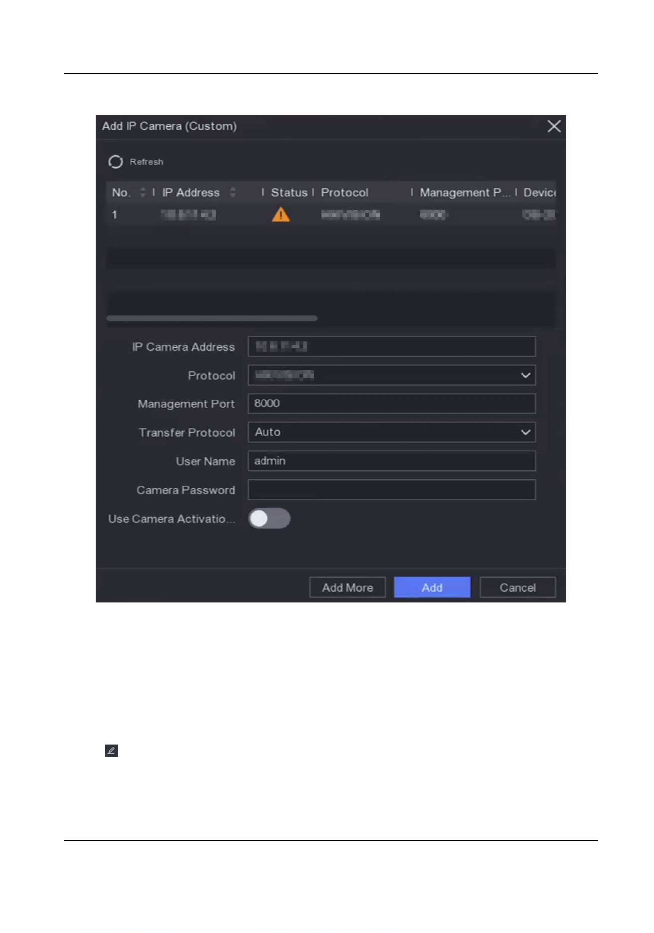
Figure 5-5 Add Network Camera
Edit Connected Network Camera
You can edit the IP address, protocol and other parameters of the added network cameras.
Steps
1.
Go to Conguraon → Camera → IP Camera .
2.
Click to edit the selected camera.
Channel Port
Network Video Recorder User Manual
25

If the connected device is an encoding device with mulple channels, you can select the
channel port No. to choose a connecng channel.
3.
Click OK.
Upgrade Network Camera
The Network camera can be remotely upgraded through the device.
Before You Start
●
Ensure you have inserted the USB ash drive to the device, and it contains the network camera
upgrade rmware.
●
Ensure your network camera is on the same network segment with your video recorder.
●
Ensure the network connecon is valid and correct.
Steps
1.
Go to Conguraon → Camera → IP Camera .
2.
Click .
3.
Click Yes to conrm.
4.
Select the camera upgrade rmware from your storage device.
5.
Click Upgrade to start upgrading. The camera will restarted automacally aer upgrade
completed.
Congure Advanced Camera Parameters
You can congure advanced camera parameters like camera IP address, camera password, etc.
Before You Start
●
Ensure your network camera is on the same network segment with your video recorder.
●
Ensure the network connecon is valid and correct.
Steps
1.
Go to Conguraon → Camera → IP Camera .
2.
Click
.
3.
Set camera parameters like IP address, camera password, etc.
4.
Click Apply.
5.3.2 OSD Sengs
Congure OSD (On-Screen Display) sengs for the camera, including date format, camera name,
etc.
Steps
1.
Go to Conguraon → Camera → OSD .
2.
Select a camera.
Network Video Recorder User Manual
26
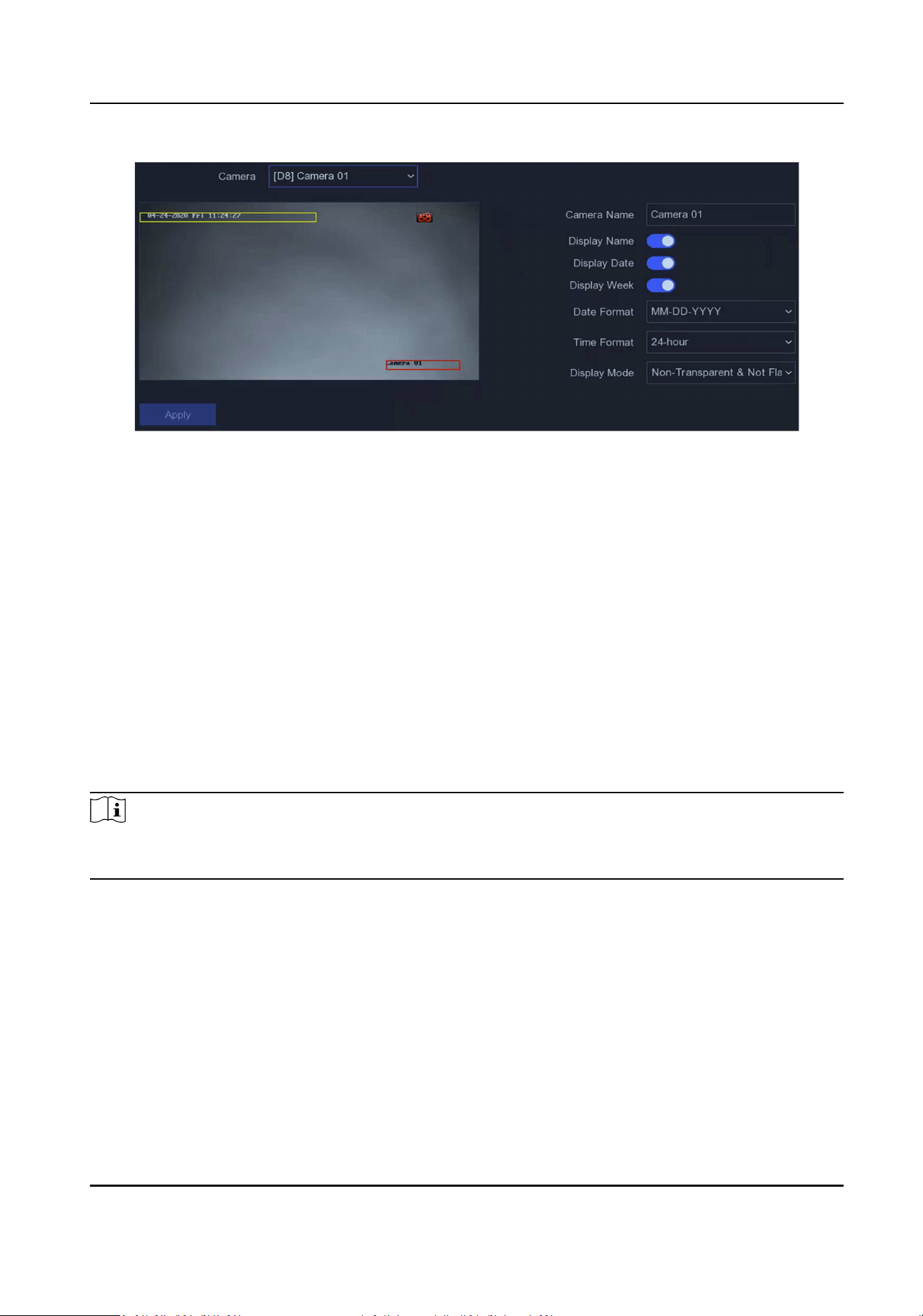
Figure 5-6 OSD
3.
Set parameters as your desire.
4.
Drag the text frames on the preview window to adjust the OSD posion.
5.
Click Apply.
5.3.3 Moon
Moon Detecon
Moon detecon enables the video recorder to detect the moving objects in the monitored area
and trigger alarms. The device can analyze videos that contain human and vehicle, and discard
alarms which are not triggered by human or vehicle.
Steps
Note
If your device VCA Mode can be set as By NVR, this funcon would enabled by default. The default
detecon area is full screen.
1.
Go to Conguraon → Camera → Event → Moon Detecon .
Network Video Recorder User Manual
27

Figure 5-7 Moon Detecon
2.
Select a camera.
3.
Turn on Enable.
4.
Set VCA Mode as By NVR or By Camera.
By NVR
The moon detecon event will be analyzed by NVR. The device can analyze videos that
contain human and vehicle. Only the target of selected type (human or vehicle) will trigger
alarms, which can reduce false alarms that are caused by other objects.
By Camera
The moon detecon event will be analyzed by camera.
5.
Set the moon detecon area.
-
Click Draw Area or Clear to draw or clear areas. The rst area is set as full screen by default.
-
Click Full Screen to set the moon detecon area as full screen. You can drag on the preview
window to draw moon detecon areas.
6.
Adjust Sensivity. Sensivity allows you to calibrate how easily movement could trigger the
alarm. A higher value results in the more readily to triggers moon detecon.
7.
Oponal: Set Target Detecon as Human or Vehicle to discard alarms which are not triggered
by human or vehicle.
Note
When VCA Mode is set as By NVR, the human/vehicle target detecon is conicted with 4K/2K
output resoluon, please lower the resoluon.
8.
Set the arming schedule. Refer to Congure Arming Schedule for details.
9.
Set the linkage acons. Refer to Congure Alarm Linkage Acon for details.
10.
Click Apply.
Network Video Recorder User Manual
28

Congure Arming Schedule
Steps
1.
Select Arming Schedule.
2.
Choose one day of a week and set the me segment. Up to eight me periods can be set within
each day.
Note
Time periods shall not be repeated or overlapped.
Figure 5-8 Set Arming Schedule
3.
Click Apply.
Congure Alarm Linkage Acon
Alarm linkage acons will be acvated when an alarm or excepon occurs.
Steps
1.
Click Linkage Acon.
2.
Set normal linkage acons, alarm output linkage acons, trigger channel, etc.
Alarm Pop-up Window
The local monitor will pop up the alarming channel image when an alarm is triggered. It
requires to select the alarming channel(s) in Trigger Channel.
Buzzer Alarm
It will trigger a buzzer beep when an alarm is triggered.
Nofy Surveillance Center
The device will send an excepon or alarm signal to the remote client soware when an
alarm is triggered.
Send Email
Network Video Recorder User Manual
29

It will send an email with alarm informaon when an alarm is triggered.
Trigger Channel
The selected channel(s) will start recording. It requires to congure the recording schedule
for the channel in Conguraon → Record → Schedule .
3.
Click Apply.
5.4 Device Access
5.4.1 Switch
Add and manage switches.
Quick Add Switch
Quick add switch(es) in the same network segment with the video recorder. If the switch is not
acvated, it will be added with the camera acvaon password.
Steps
1.
Go to Conguraon → Device Access → Switch .
2.
In the Online Device List, check the switch(es) to be added and click Add to add switch(es) in the
same network segment with the video recorder using the channel default password.
Add Switch Manually
Steps
1.
Go to Conguraon → Device Access → Switch .
2.
In the Added Device List, click Add and set the parameters of the device.
Table 5-1 Device Parameter Descripon
Parameter Descripon
IP Address The IP address of the switch.
Management Port It is recommended to keep the default conguraon.
User Name / Password The user name / password of the switch.
Use Camera Acvaon
Password
Use the camera acvaon password of the video recorder to add
the switch.
3.
Click Add and Connue and repeat operaon unl all devices have been added.
4.
Click Add.
Network Video Recorder User Manual
30

5.4.2 Non-Video Event (Easy Mode)
Congure non-video events.
Steps
1.
Go to Conguraon → Device Access → Non-Video Event .
2.
Select a device.
3.
Select the alarm content.
4.
Congure the arming schedule.
5.
Congure the linkage acon.
Buzzer Alarm
It will trigger a buzzer beep when an alarm is triggered.
Nofy Surveillance Center
The device will send an excepon or alarm signal to the remote client soware when an
alarm is triggered.
Send Email
It will send an email with alarm informaon when an alarm is triggered.
6.
Click Apply.
5.4.3 IP Speaker
Add and manage IP speaker. IP speaker can be linked to a camera to realize sound alarm linkage
and two-way audio.
Quick Add IP Speaker
Quick add IP speakers in the same network segment with the video recorder. If the IP speaker is
not acvated, it will be added with the camera acvaon password.
Steps
1.
Go to Conguraon → Device Access → IP Speaker .
2.
In the Online Device List, check the IP speaker(s) to be added and click Add to add IP speaker(s)
in the same network segment with the video recorder using the camera acvaon password.
Note
Up to 4 IP speakers can be added.
Add IP Speaker Manually
Steps
1.
Go to Conguraon → Device Access → IP Speaker .
Network Video Recorder User Manual
31

2.
In the Added Device List, click Add and set the parameters of the device.
Table 5-2 Device Parameter Descripon
Parameter Descripon
IP Address The IP address of the IP speaker.
Management Port It is recommended to keep the default conguraon.
User Name / Password The user name / password of the IP speaker.
Use Camera Acvaon
Password
Use the camera acvaon password of the video recorder to add
the IP speaker.
3.
Click Add and Connue and repeat operaon unl all devices have been added.
Note
Up to 4 IP speakers can be added.
4.
Click Add.
Link IP Speaker to Channel
IP speakers can be linked to camera to realize sound alarm linkage and two-way audio.
Steps
1.
Go to Conguraon → Device Access → IP Speaker .
2.
In the Added Device List, select a device and click .
3.
Select the channel(s) to link.
4.
Click OK.
Batch Time Sync
Supports batch me sync of the IP speakers.
Steps
1.
Go to Conguraon → Device Access → IP Speaker .
2.
In the Added Device List, click Batch Time Sync.
3.
Turn on Enable Time Sync.
4.
Set Time Sync Interval.
5.
Click OK.
Congure Audio Parameters
Steps
1.
Go to Conguraon → Device Access → IP Speaker .
Network Video Recorder User Manual
32

2.
Click Audio Parameter.
3.
Congure the volume of the IP speaker.
Media Library
Supports imporng audio from the external storage to the media library.
Steps
1.
Go to Conguraon → Device Access → IP Speaker .
2.
In the Added Device List, click Media Library.
3.
Select the IP speaker you want to import audio to.
-
Select the IP speaker(s) in the list on the le, and click Import.
-
Click Batch Import Audio, select the IP speaker(s), and click OK.
4.
Select device name, path, and audio le(s).
5.
Click Import.
Note
The le should be MP3 or WAV le within 1 MB.
5.5 PoE Sengs
Congure PoE power and PoE binding.
5.5.1 Congure PoE Power
Steps
1.
Go to Conguraon → PoE Sengs → PoE Power Conguraon .
2.
Enable or disable long network cable mode by selecng Long Distance or Short Distance.
Long Distance
Long-distance (100 to 300 meters) network transmissions via PoE interface.
Short Distance
Short-distance (< 100 meters) network transmission via PoE interface.
Note
●
The PoE ports are enabled with the short distance mode by default.
●
The bandwidth of IP camera connected to the PoE via long network cable (100 to 300 meters)
cannot exceed 6 Mbps.
●
The allowed max. long network cable may be less than 300 meters depending on dierent IP
camera models and cable materials.
Network Video Recorder User Manual
33

●
When the transmission distance reaches 100 to 250 meters, you must use the CAT5e or CAT6
network cable to connect with the PoE interface.
●
When the transmission distance reaches 250 to 300 meters, you must use the CAT6 network
cable to connect with the PoE interface.
3.
Click Apply.
4.
Connect PoE cameras to your device PoE interfaces with network cables.
5.5.2 Congure PoE Binding
Steps
1.
Go to Conguraon → PoE Sengs → PoE Binding Conguraon .
2.
Check or uncheck to enable or disable PoE channel(s).
Note
You can disable a PoE channel to addionally increase a normal IP channel resource.
3.
Set the Access Device Type of PoE1 to PoE4.
4.
Click Apply.
5.6 Recording Management
5.6.1 Storage Device
Inialize HDD
A newly installed hard disk drive (HDD) must be inialized before it can be used to save videos and
informaon.
Before You Start
Install at least an HDD to your video recorder. For detailed steps, refer to Quick Start Guide.
Steps
1.
Go to Conguraon → Record → Storage .
2.
Select an HDD.
3.
Click Init.
Repair Database
Repair an HDD that with error in database. Please operate it with the help of professional
technical support.
Network Video Recorder User Manual
34
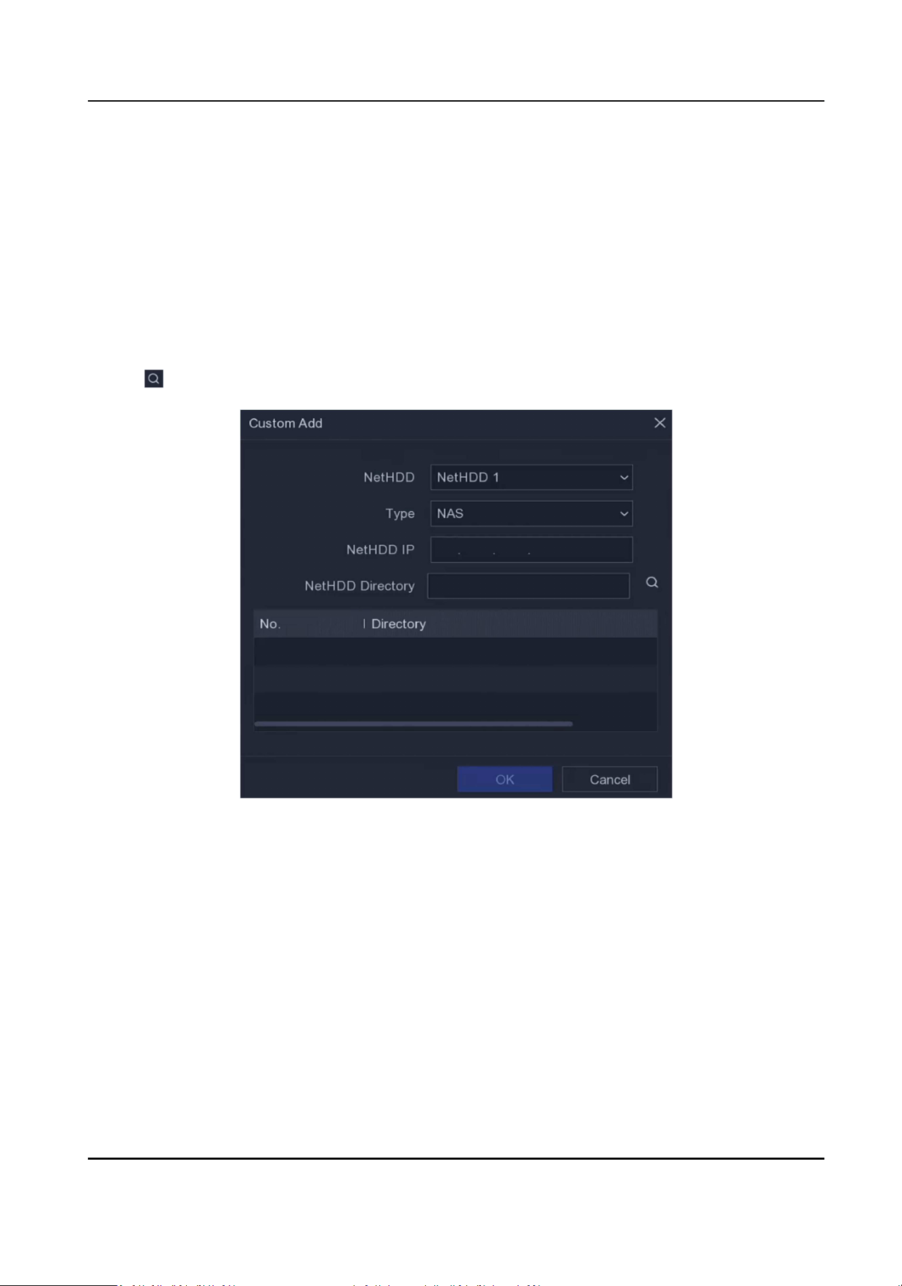
Add Network Disk
You can add the allocated NAS or IP SAN disk to the video recorder, and use it as a network HDD.
Steps
1.
Go to Conguraon → Record → Storage .
2.
Click Add.
3.
Select NetHDD.
4.
Set Type as NAS or IP SAN.
5.
Enter NetHDD IP address.
6.
Click to search the available disks.
Figure 5-9 Add NetHDD
7.
Select NAS disk from the list, or manually enter the directory in NetHDD Directory.
8.
Click OK. The added NetHDD will be displayed in the storage device list.
5.6.2 Congure Recording Schedule
Video recorder will automacally start/stop recording according to the congured schedule.
Congure Connuous Recording
Steps
1.
Go to Conguraon → Record → Parameter .
Network Video Recorder User Manual
35

2.
Set the connuous main stream/sub-stream recording parameters for the camera. Refer to
Congure Recording Parameter for details.
3.
Go to Conguraon → Record → Schedule .
4.
Select recording type as Connuous. Refer to Edit Schedule for details.
Congure Event Recording
You can congure the recording triggered by the moon detecon.
Steps
1.
Go to Conguraon → Camera → Moon .
2.
Congure the event detecon and select the channels to trigger the recording when an event
occurs.
3.
Go to Conguraon → Record → Parameter .
4.
Set the connuous main stream / sub-stream recording parameters for the camera. Refer to
Congure Recording Parameter for details.
5.
Go to Conguraon → Record → Schedule .
6.
Select recording type as Event. Refer to Edit Schedule for details.
Edit Schedule
Steps
1.
Go to Conguraon → Record → Schedule .
Figure 5-10 Recording Schedule
Connuous
Connuous recording.
Event
Network Video Recorder User Manual
36

Recording is triggered by events.
2.
Select a camera in Camera No.
3.
Turn on Enable.
4.
Congure the recording schedule.
Edit
Schedule
a. Click Edit.
b. Select a day to congure in Weekday.
c. To set an all-day recording schedule, check All Day and select schedule type.
d. To set other schedules, uncheck All Day, and set Start/End Time and
schedule type.
Note
Up to 8 periods can be congured for each day. And the me periods cannot
be overlapped with each other.
e. Click OK to save the sengs and go back to upper level menu.
Draw
Schedule
a. Click to select schedule type as Connuous or Event.
b. On the table, drag the mouse on the desired period to draw a colored bar.
5.
Click Apply.
5.6.3 Congure Recording Parameter
Steps
1.
Go to Conguraon → Record → Parameter .
2.
Congure recording parameters.
Main Stream
Main stream refers to the primary stream that aects data recorded to the hard disk drive
and will directly determine your video quality and image size. Comparing with the sub-
stream, the main stream provides a higher quality video with higher resoluon and frame
rate.
Sub-Stream
Sub-stream is a second codec that runs alongside the mainstream. It allows you to reduce the
outgoing internet bandwidth without sacricing your direct recording quality. Sub-stream is
oen exclusively used by smartphone applicaons to view live video. Users with limited
internet speeds may benet most from this seng.
Resoluon
Image resoluon is a measure of how much detail a digital image can hold: the greater the
resoluon, the greater the level of detail. Resoluon can be specied as the number of pixel-
columns (width) by the number of pixel-rows (height), e.g.,1024×768.
Frame Rate
Network Video Recorder User Manual
37

Frame rate refers to how many frames are captured each second. A higher frame rate is
advantageous when there is movement in the video stream, as it maintains image quality
throughout.
Max. Bitrate
Set the maximum bit rate. The bit rate (in Kbit/s or Mbit/s) is oen referred to as speed, but
actually denes the number of bits/me unit and not distance/me unit.
Encoding Type
Set the video encoding type.
Enable H.265+
Enable or Disable H.265+.
Note
Higher resoluon, frame rate, and bitrate provide you beer video quality, but it also requires
more internet bandwidth and uses more storage space on the hard disk drive.
3.
Click Apply.
Network Video Recorder User Manual
38

Chapter 6 Conguraon (Expert Mode)
Go to Conguraon , and click Expert Mode at the lower-le corner.
6.1 System Conguraon
6.1.1 General
Congure Basic Sengs
You can congure the language, system me, output resoluon, mouse pointer speed, lock screen
password, etc.
Go to Conguraon → System → General → Basic Sengs , congure the parameters as your
desire, and click Apply.
Language
The default language is English.
VGA/HDMI Resoluon
Select the output resoluon, which must be the same with the resoluon of the VGA/HDMI
display.
Mouse Pointer Speed
Set the speed of mouse pointer. 4 levels are congurable.
Local Auto Login
Aer Local Auto Login is enabled, the device password will no longer be veried unl the admin
user logs out. Please take good care of your device and admin password to prevent losses.
Wizard
The wizard will pop up aer the device starts up.
Enhanced Decoding Mode
Disabling enhanced decoding mode will reduce the local decoding capability by half and restart
the device.
Congure More Sengs
You can congure your device name, lock screen me, output mode, etc.
Go to Conguraon → System → General → More Sengs , congure the parameters as your
desire, and click Apply.
Network Video Recorder User Manual
39
Device Name
Edit the video recorder name.
Device No.
The number is required in the connecon with remote control, network keyboard, etc. Edit the
serial number of video recorder. The device number ranges from 1 to 255, and the default value
is 255.
Lock Screen
Set meout me for lock screen.
Enable HDMI/VGA Simultaneous Output
Enable simultaneous output of HDMI and VGA interfaces.
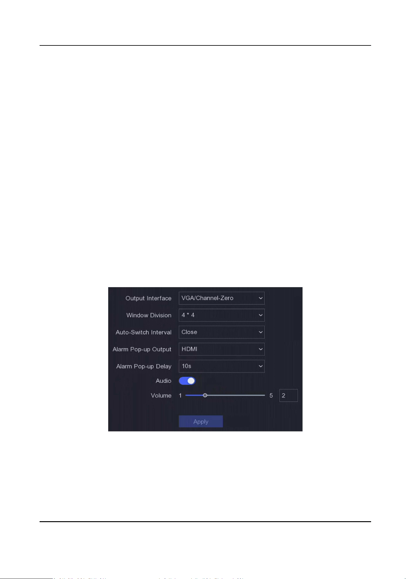
6.1.2 Live View
Congure General Parameters
You can congure the output interface, mute or turning on the audio, event output interface, etc.
Steps
1.
Go to Conguraon → System → Live View → General .
Figure 6-1 Live View-General
2.
Congure the Live View parameters.
Window Division
Select the live view window division.
Network Video Recorder User Manual
40

Auto Switch Interval
The me to dwell in a camera before switching to next camera when auto-switch in live view
is enabled.
Alarm Pop-up Output
Select the output to show alarm video.
Alarm Pop-up Delay
Set the me to show alarm event image.
Audio
Turn on/o audio output for the selected video output.
Volume
Adjust the live view, playback, and two-way audio volume for the selected video output
interface.
3.
Click Apply.
Congure Live View Layout
Steps
1.
Go to Conguraon → System → Live View → View .
2.
Set Output Interface.
3.
Select a window, and double click a camera the list you would like to display. means no
camera is displayed on the window.
4.
Oponal: Click
or to start or stop live view of all cameras.
5.
Click Apply.
Congure Channel-Zero Encoding
Enable the channel-zero encoding when you need to get a remote view of many channels in real
me from a web browser or CMS (Client Management System) soware, in order to decrease the
bandwidth requirement without aecng the image quality.
Steps
1.
Go to Conguraon → System → Live View → General .
2.
Set Video Output Interface as Channel-Zero.
3.
Go to Conguraon → System → Live View → Channel-Zero .
Network Video Recorder User Manual
41

Figure 6-2 Channel-Zero
4.
Turn on Enable.
5.
Congure Frame Rate, Max. Bitrate Mode, and Max. Bitrate. The higher frame rate and bitrate
require higher bandwidth requirement.
6.
Click Apply.
6.1.3 User
Refer to User for details.
6.2 Network Conguraon
6.2.1 TCP/IP
TCP/IP must be properly congured before you operate video recorder over network.
Steps
1.
Go to Conguraon → Network → General → TCP/IP .
2.
Congure network parameters.
Working Mode
Mul-address Mode
The parameters of the two NIC cards can be congured independently. You can select
LAN1 or LAN2 in the NIC type eld for parameter sengs. You can select one NIC card as
default route. And then the system is connecng with the extranet and the data will be
forwarded through the default route.
Net-fault Tolerance Mode
Network Video Recorder User Manual
42

The two NIC cards use the same IP address, and you can select the Main NIC to LAN1 or
LAN2. By this way, in case of one NIC card failure, the video recorder will automacally
enable the other standby NIC card so as to ensure the normal running of the whole
system.
Load Balance Mode
By using the same IP address and two NIC cards share the load of the total bandwidth,
which enables the system to provide two Gigabit network capacity.
Note
Working mode is only available for certain models.
NIC Type
Select NIC type as your desire. If your device supports Wi-Fi dongle funcon, the NIC of Wi-Fi
dongle would be selectable aer a suitable Wi-Fi dongle is installed.
DHCP
If the DHCP server is available, you can check Enable DHCP to automacally obtain an IP
address and other network sengs from that server.
MTU
The maximum transmission unit (MTU) is the size of the largest network layer protocol data
unit that can be communicated in a single network transacon.
Default Route
Select a route as your desire. If your device supports Wi-Fi dongle funcon, the route of Wi-Fi
dongle would be selectable aer a suitable Wi-Fi dongle is installed.
Auto Obtain DNS
If DHCP is checked. You can check Obtain DNS Automacally to obtain Preferred DNS Server
and Alternate DNS Server.
3.
Click Apply.
6.2.2 DDNS
Dynamic domain name server (DDNS) maps dynamic user IP addresses to a xed domain name
server.
Before You Start
Register DynDNS, PeanutHull and NO-IP services with your ISP.
Steps
1.
Go to Conguraon → Network → General → DDNS .
Network Video Recorder User Manual
43
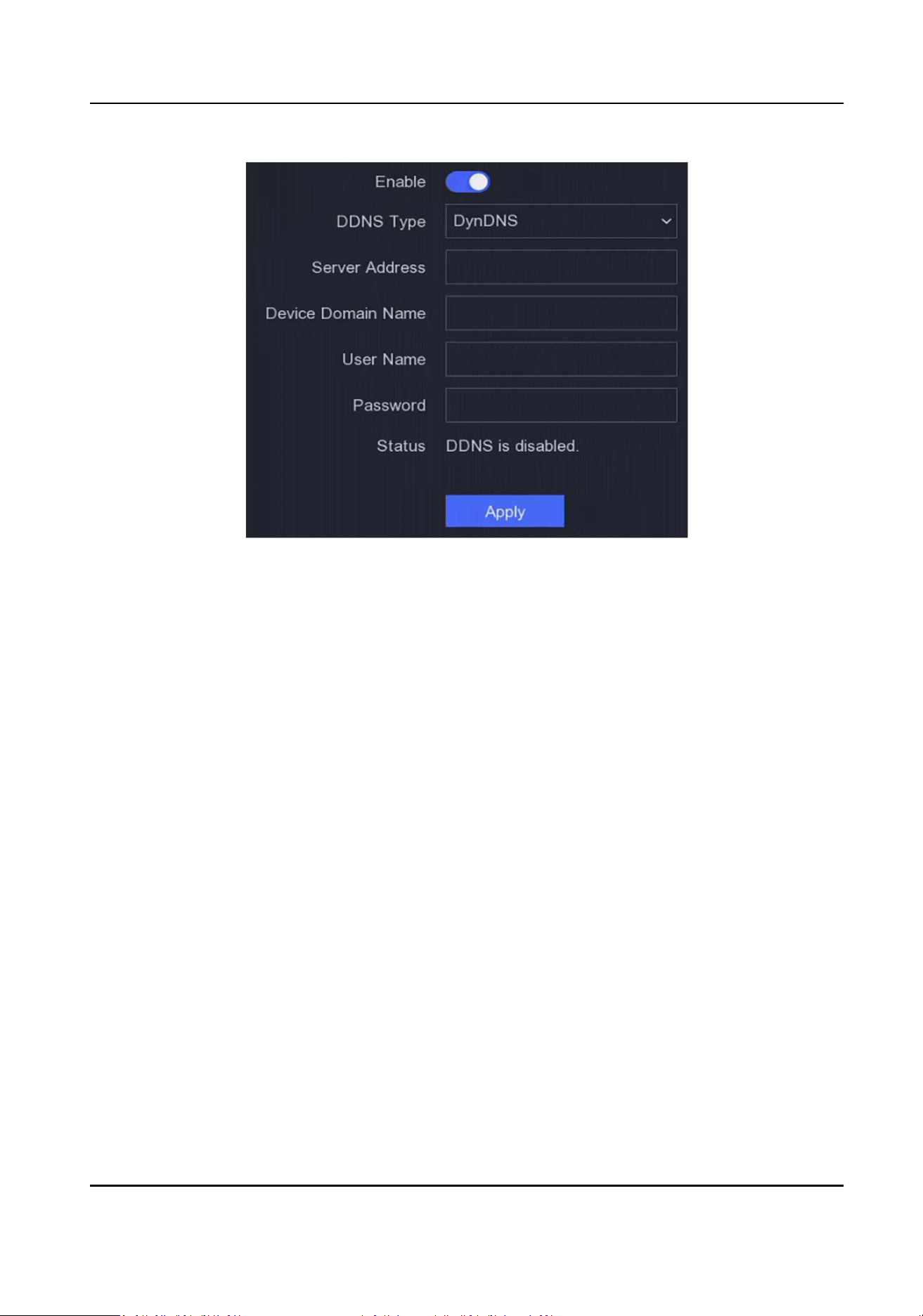
Figure 6-3 DDNS
2.
Turn on Enable.
3.
Select a DDNS type.
4.
Enter parameters including service address, domain name, etc.
5.
Click Apply.
What to do next
You can view DDNS status in Status.
6.2.3 NAT
Two ways are provided for port mapping to realize the remote access via the cross-segment
network, UPnP™ and manual mapping.
Before You Start
Enable the UPnP™ funcon of your router if UPnP™ is required. When the device network working
mode is mul-address, the default device route should be on the same network segment as the
LAN IP address of the router.
Steps
1.
Go to Conguraon → Network → General → NAT .
Network Video Recorder User Manual
44

Figure 6-4 NAT
2.
Turn on Enable.
3.
Select Mapping Type as Manual or Auto
Auto The port mapping items are read-only, and the external ports are set by the router
automacally. You can click Refresh to get the latest status of the port mapping.
Manual Select an external port type. Click
to edit External Port. You can use the default
external port No., or change it according to actual requirements. External Port
indicates the port No. for port mapping in the router.
The value of the RTSP port No. should be 554 or between 1024 and 65535, while
the value of the other ports should be between 1 and 65535 and the value must be
dierent from each other. If mulple devices are congured for the UPnP™ sengs
under the same router, the value of the port No. for each device should be unique.
4.
Set the virtual server of your router, including internal source port, external source port, etc. The
virtual server parameters shall be corresponding with your device port.
6.2.4 NTP
Your device can connect to a network me protocol (NTP) server to ensure that the system me is
accurate.
Steps
1.
Go to Conguraon → Network → General → NTP .
2.
Turn on Enable.
3.
Enter the parameters.
Interval
Time interval between two me synchronizaon with NTP server.
NTP Server
IP address of the NTP server.
Network Video Recorder User Manual
45

4.
Click Apply.
6.2.5 Upload Logs to the Server
You can upload system logs to the server for backup.
Steps
1.
Go to Conguraon → Network → General → Log Server Sengs .
Figure 6-5 Log Server Sengs
2.
Turn on Enable
3.
Set Upload Time Interval, Server IP Address, and Port.
4.
Oponal: Click Test to test if parameters are valid.
5.
Click Apply.
6.2.6 Ports (More Sengs)
Set dierent port types to enable relevant funcons as your desire.
Go to Conguraon → Network → General → More Sengs .
Alarm Host IP/Port
The device will send the alarm event or excepon message to the alarm host when an alarm is
triggered. The remote alarm host must have the client management system (CMS) soware
installed.
Alarm Host IP refers to the IP address of the remote PC on which the CMS soware (e.g.,
iVMS-4200) is installed, and the Alarm Host Port (7200 by default) must be the same as the
alarm monitoring port congured in the soware.
Server Port
For remote client soware access. Ranges from 2000 to 65535. The default value is 8000.
HTTP Port
Network Video Recorder User Manual
46
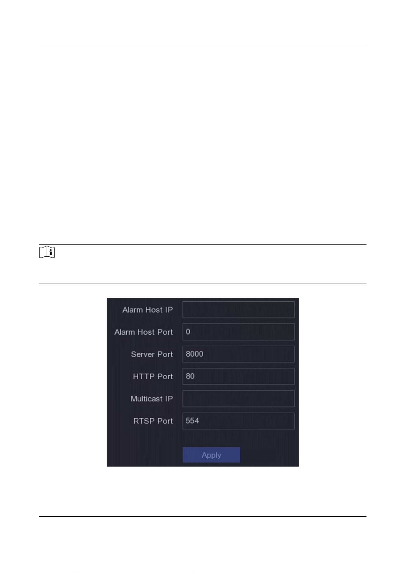
For remote web browser access. The default value is 80.
Mulcast IP
Mulcast can be congured to enable live view for cameras that exceed the maximum number
allowed through network. A mulcast IP address covers Class-D IP ranging from 224.0.0.0 to
239.255.255.255 and it is recommended to use the IP address ranging from 239.252.0.0 to
239.255.255.255.
When adding a device to the CMS soware, the mulcast address must be the same as that of
the device.
RTSP Port
RTSP (Real Time Streaming Protocol) is a network control protocol designed for use in
entertainment and communicaons systems to control streaming media servers. The port is 554
by default.
Output Bandwidth Limit
You can check the checkbox to enable output bandwidth limit.
Output Bandwidth
Aer enable the output bandwidth limit, input the output bandwidth.
Note
●
The output bandwidth limit is used for the remote live view and playback.
●
The default output bandwidth is the maximum limit.
Figure 6-6 Port Sengs
Network Video Recorder User Manual
47
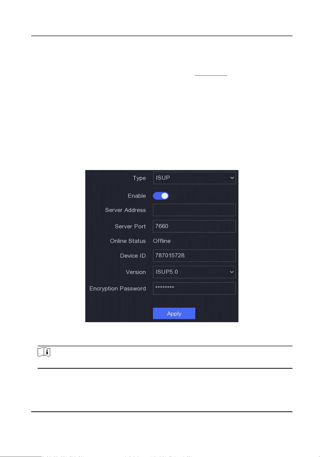
6.2.7 Hik-Connect
Go to Conguraon → Network → Plaorm Access . Refer to Hik-Connect for details.
6.2.8 ISUP
SDK is based on Intelligent Security Uplink Protocol (ISUP). It provides APIs, library les, and
commands for the third-party plaorm to access devices such as NVRs, speed domes, DVRs,
network cameras, mobile NVRs, mobile devices, decoding devices, etc. With this protocol, the
third-party plaorm can realize funcons like live view, playback, two-way audio, PTZ control, etc.
Steps
1.
Go to Conguraon → Network → Plaorm Access .
2.
Set Type as ISUP.
Figure 6-7 ISUP
3.
Turn on Enable.
Note
Enabling ISUP will disable other plaorm access.
4.
Set the related parameters.
Server Address
Network Video Recorder User Manual
48

The plaorm server IP address.
Server Port
The plaorm server port, ranges from 1024 to 65535. The actual port shall be provided by
the plaorm.
Device ID
The Device ID shall be provided by the plaorm.
Version
ISUP protocol version, only V5.0 is available.
Encrypon Password
Encrypon password is required when using ISUP V5.0 version, it provides more secure
communicaon between the device and plaorm. Enter it for vericaon aer the device is
registered to the ISUP plaorm.
5.
Click Apply to save the sengs and restart the device.
What to do next
You can see the online status (online or oine) aer the device is restarted.
6.2.9 OTAP Service
Steps
1.
Go to Conguraon → Network → Plaorm Access .
2.
Set Type as OTAP Service.
3.
Turn on Enable.
Note
Enabling OTAP service will disable other plaorm access.
4.
Set the related parameters.
Server Address
The plaorm server IP address.
Port
The plaorm server port ranges from 1 to 65535. The default value is 7800. The actual port
shall be provided by the plaorm.
Device ID
The Device ID shall be provided by the device.
Key
The key is used for vericaon when the server receives the registraon informaon. 6 to 12
characters are allowed for the key. The default key is abc12345.
5.
Click Apply to save the sengs and restart the device.
Network Video Recorder User Manual
49

What to do next
You can see the registraon status (online or oine) aer the device is restarted.
6.2.10 Email
Go to Conguraon → Network → Email . Refer to Email for details.
6.3 Camera Management
6.3.1 Network Camera
Add Automacally Searched Online Network Camera
Add the network cameras to your video recorder.
Before You Start
●
Ensure your network camera is on the same network segment with your video recorder.
●
Ensure the network connecon is valid and correct.
●
Ensure the network camera password is the same as your video recorder.
Steps
1.
Go to Conguraon → Camera → Camera .
2.
Click Online Device List. The online cameras on the same network segment will be displayed in
the list.
3.
Oponal: Click Edit IP to edit camera IP addresses in batch. The system will allocate IP addresses
to the selected cameras in order.
Note
Ensure the selected cameras are acvated.
4.
Select a network camera, and click Add to add it.
Add Network Camera Manually
Add the network cameras to your video recorder.
Before You Start
●
Ensure your network camera is on the same network segment with that of your video recorder.
●
Ensure the network connecon is valid and correct.
●
Ensure the network camera is acvated.
Steps
1.
Go to Conguraon → Camera → Camera .
Network Video Recorder User Manual
50
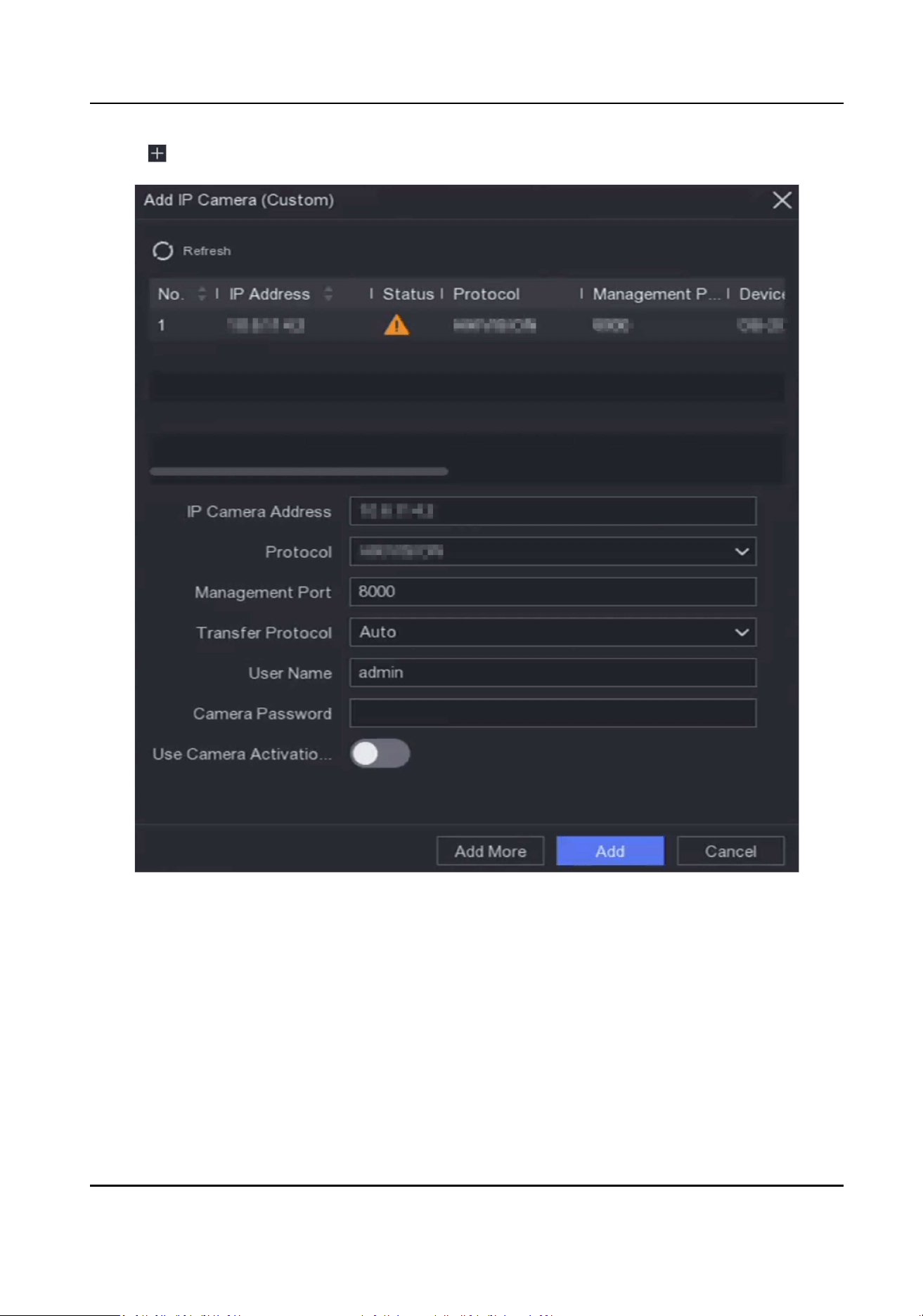
2.
Click .
Figure 6-8 Add IP Camera
3.
Enter network camera parameters.
Use Camera Acvaon Password
If it is enabled, the video recorder will add the camera by the set channel default password.
4.
Click Add.
Network Video Recorder User Manual
51

Add Network Camera on Dierent Network Segment
If your network camera is on a dierent network segment, the device can search its IP address
within a range of IP addresses, and add it.
Before You Start
●
Ensure the network connecon is valid and correct.
●
Ensure the network camera password is the same as your video recorder.
Steps
1.
Go to Conguraon → Camera → Camera → IP Channel .
2.
Click Advanced Search.
3.
Enter Network Segment.
Figure 6-9 Enter Network Segment
4.
Click Add.
Add Network Camera Through Plug-and-Play
If an inacve network camera or third party ONVIF camera is connected to your network, the video
recorder may automacally detect and add the camera, or nofy you to manually add it.
Steps
1.
Go to Conguraon → Camera → Camera → IP Channel .
2.
Click More.
3.
Select Plug-and-Play.
4.
Oponal: Enable Auto Add Network Camera. The video recorder would automacally detect
and add the inacve network camera or third party ONVIF camera.
Figure 6-10 Auto Add Network Camera
Network Video Recorder User Manual
52

Note
If you turn o Auto Add Network Camera, when an inacve network camera or third party
ONVIF camera is connected to your network, the video recorder would automacally detect it
and nofy you to add it.
Edit Network Camera
You can edit the IP address, protocol and other parameters of network cameras.
Steps
1.
Go to Conguraon → Camera → Camera .
2.
Click of an added network camera.
Channel Port
If the connected device is an encoding device with mulple channels, you can choose the
channel to connect by selecng the channel port No. in the drop-down list.
3.
Oponal: Click Edit IP to edit camera IP addresses in batch. The system will allocate IP addresses
to the selected cameras in order.
4.
Click OK.
Upgrade Network Camera
The Network camera can be remotely upgraded through the device.
Before You Start
●
Ensure you have inserted the USB ash drive to the device, and it contains the network camera
upgrade rmware.
●
Ensure your network camera is on the same network segment with your video recorder.
●
Ensure the network connecon is valid and correct.
Steps
1.
Go to Conguraon → Camera → Camera .
2.
Click .
3.
Click Yes to conrm.
4.
Select the camera upgrade rmware from your storage device.
5.
Click Upgrade to start upgrading. The camera will restarted automacally aer upgrade
completed.
Add Network Camera Through PoE
The PoE interfaces enable the device to transfer electrical power and data to connected PoE
cameras. And the PoE interface supports the Plug-and-Play funcon. Connectable PoE camera
Network Video Recorder User Manual
53

number varies with device models. If you disable a PoE interface, you can also use it to connect to
an online network camera.
Add PoE Camera
Steps
1.
Go to Conguraon → Camera → Camera → PoE Sengs .
2.
Enable or disable long network cable mode by selecng Long Distance or Short Distance.
Long Distance
Long-distance (100 to 300 meters) network transmissions via PoE interface.
Short Distance
Short-distance (< 100 meters) network transmission via PoE interface.
Note
●
The PoE ports are enabled with the short distance mode by default.
●
The bandwidth of IP camera connected to the PoE via long network cable (100 to 300 meters)
cannot exceed 6 Mbps.
●
The allowed max. long network cable may be less than 300 meters depending on dierent IP
camera models and cable materials.
●
When the transmission distance reaches 100 to 250 meters, you must use the CAT5e or CAT6
network cable to connect with the PoE interface.
●
When the transmission distance reaches 250 to 300 meters, you must use the CAT6 network
cable to connect with the PoE interface.
Network Video Recorder User Manual
54

Figure 6-11 Add PoE Camera
3.
Click Apply.
4.
Connect PoE cameras to your device PoE interfaces with network cables.
What to do next
The connected PoE camera will be displayed in Conguraon → Camera → Camera .
Add Non-PoE Network Camera
You can use the PoE channel resource to connect a non-PoE network camera.
Steps
1.
Go to Conguraon → Camera → Camera → IP Channel .
2.
Click of a channel with no linked network camera.
3.
Select Adding Method as Manual.
Plug-and-Play
The camera is physically connected to the PoE interface. You can click in the added device
list to edit its parameters.
Manual
Add IP camera without physical connecon via network cable.
4.
Set other parameters, such as user name, password, and IP address.
Network Video Recorder User Manual
55

Congure Advanced Camera Parameters
You can congure advanced camera parameters like camera IP address, camera password, etc.
Before You Start
●
Ensure your network camera is on the same network segment with your video recorder.
●
Ensure the network connecon is valid and correct.
Steps
1.
Go to Conguraon → Camera → Camera .
2.
Click .
3.
Set camera parameters like IP address, camera password, etc.
4.
Click Apply.
Import/Export IP Camera Conguraon File
The informaon of added network camera can be generated into an excel le and exported to the
local device for backup, including the IP address, port, password of admin, etc. And the exported
le can be edited on your computer, like adding or deleng the content, and copy the seng to
other devices by imporng the excel le to it.
Before You Start
Connect a backup device, such as a USB ash drive, to your video recorder.
Steps
1.
Go to Conguraon → Camera → Camera .
2.
Click More.
3.
Click Export/Import to export/import conguraon les to the connected backup device.
4.
Set the storage device and folder path.
5.
Click Export/Import.
What to do next
Aer the imporng process is completed, you must restart the video recorder.
Advanced Sengs
Steps
1.
Go to Conguraon → Camera → Camera .
2.
Click More.
3.
Congure the parameters as your desire.
H.265 Auto Switch Conguraon
If you enable the opon, the device will automacally switch to H.265 stream for the network
camera (which supports H.265 video format) for the inial access.
Network Video Recorder User Manual
56

Upgrade
Upgrade the added network cameras.
Export/Import
The informaon of added network camera can be generated into an excel le and exported to
the local device for backup, including the IP address, port, password of admin, etc. And the
exported le can be edited on your computer, like adding or deleng the content, and
copying the sengs to other devices by imporng the excel le to it.
Protocol
To connect the network cameras which are not congured with the standard protocols, you
can congure the customized protocols for them. The system provides 16 customized
protocols.
Camera Acvaon Password Sengs
Change the default password for acvang and adding network cameras. For network
cameras that are already connected, you can choose to change their passwords to this one in
the following pup-up window.
Batch Conguraon
The device can enable SVC funcon or automacally synchronize me of the selected
network cameras.
Plug-and-Play
The device can add network camera automacally.
Quick Image Output Conguraon
Aer the network camera that supports this funcon is linked to the NVR,enabling this
funcon will increase the image outpung speed of the camera.
Note
This funcon is only available for NVRs that support PoE funcon.
6.3.2 Display Sengs
Congure the OSD (On-Screen Display), image sengs, exposure sengs, day/night switch
sengs, etc.
Steps
1.
Go to Conguraon → Camera → Display .
2.
Set Camera.
3.
Congure parameters as your desire.
OSD Sengs
Congure the OSD (On-screen Display) sengs for the camera, including date/me, camera
name, etc.
Network Video Recorder User Manual
57
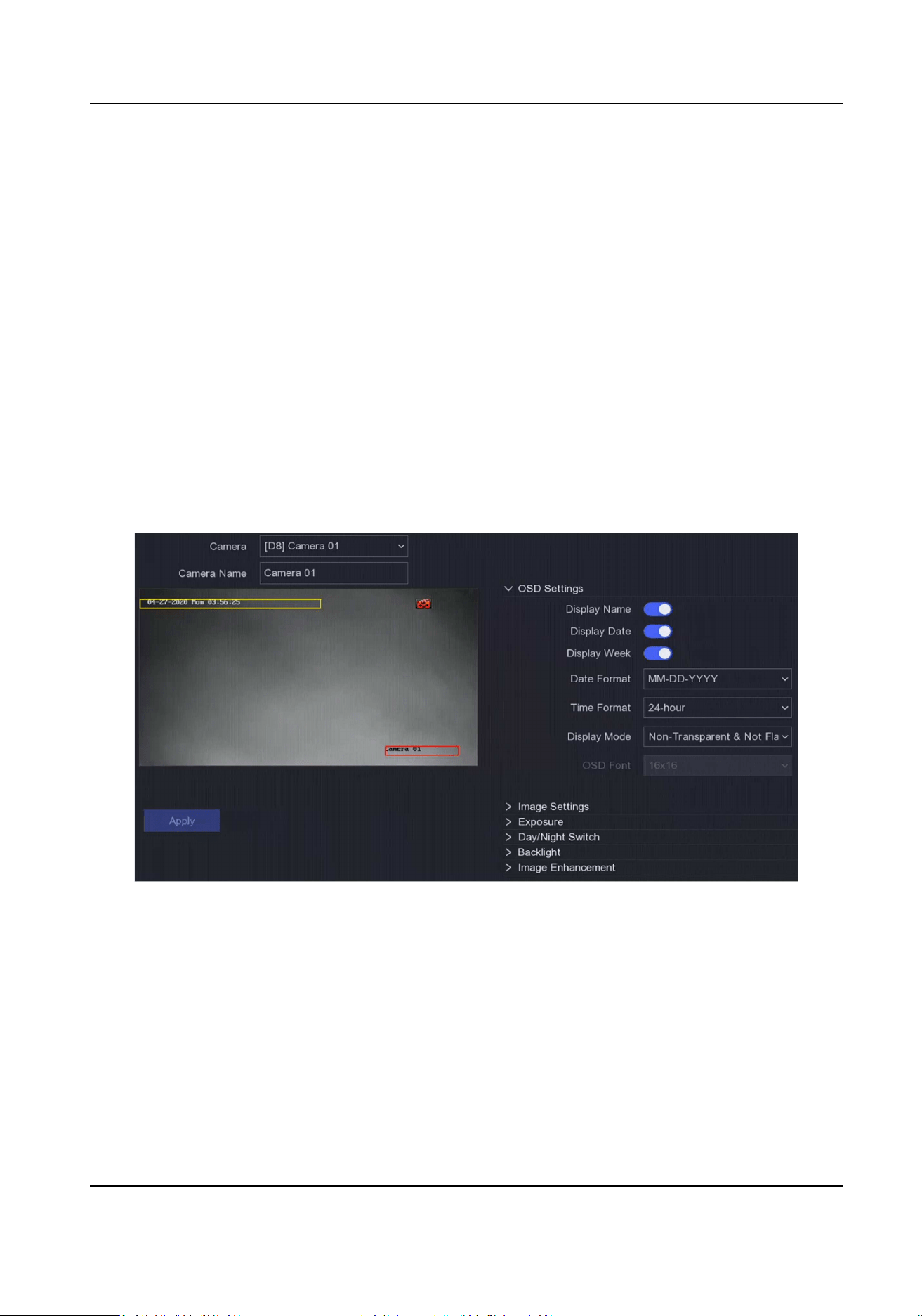
Image Sengs
Customize the image parameters including the brightness, contrast, and saturaon for the
live view and recording eect.
Exposure
Set the camera exposure me (1/10000 to 1 sec). A larger exposure value results in a brighter
image.
Day/Night Switch
The camera can be set to day, night, auto or scheduled switch mode according to the
surrounding illuminaon condions or me schedule.
Backlight
Set the camera's wide dynamic range (0 to 100). When the surrounding illuminaon and the
object have large dierences in brightness, you should set the WDR value.
Image Enhancement
For opmized image contrast enhancement.
Figure 6-12 OSD
4.
Drag the text frames on the preview window to adjust the OSD posion.
5.
Click Apply.
6.3.3 Privacy Mask
You are allowed to congure the privacy mask areas that cannot be viewed or recorded.
Steps
1.
Go to Conguraon → Camera → Privacy Mask .
Network Video Recorder User Manual
58
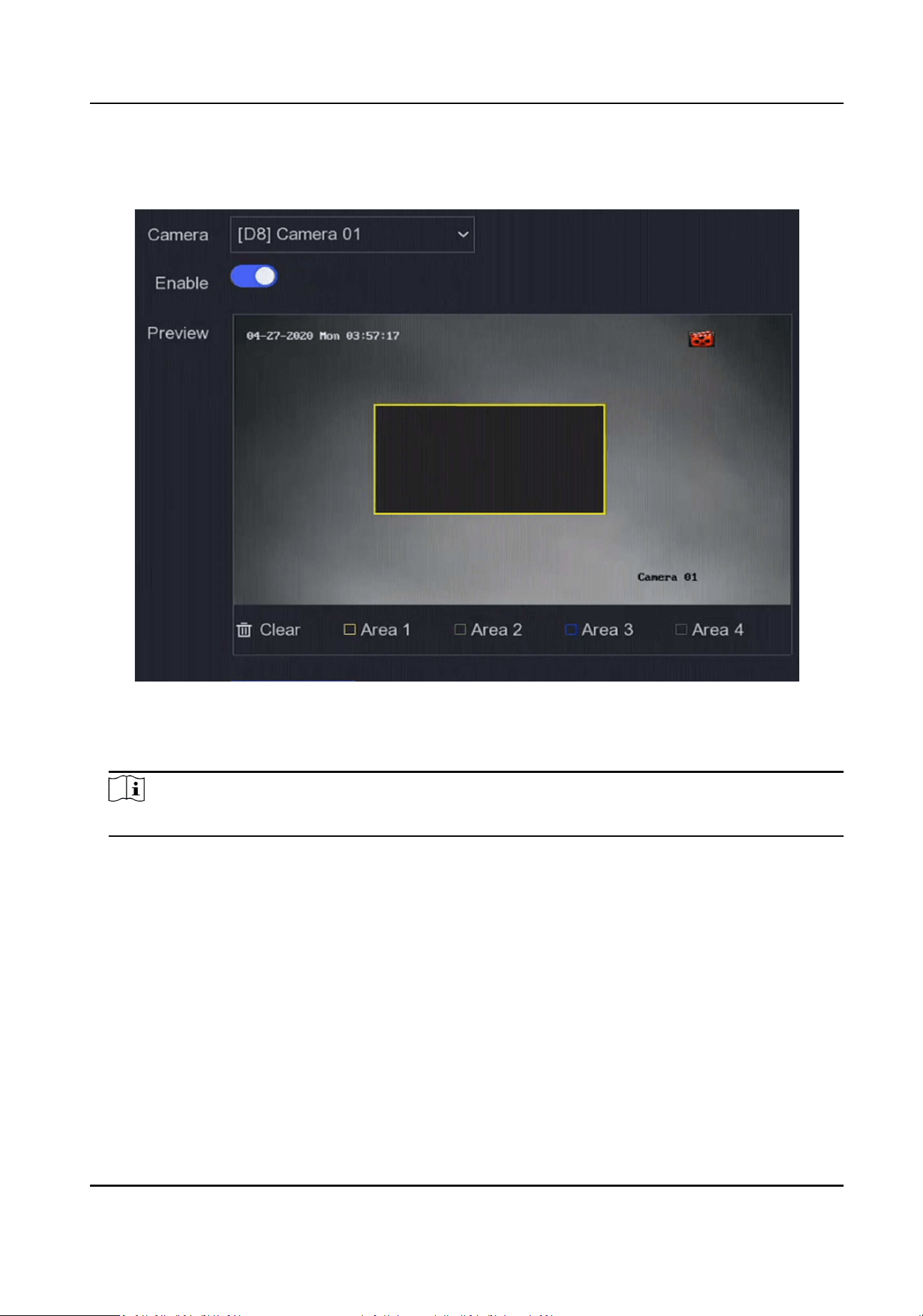
2.
Select Camera.
3.
Turn on Enable.
Figure 6-13 Privacy Mask
4.
Drag to draw an area on the window. The frames of the areas will be marked with dierent
colors.
Note
Up to 4 privacy mask areas can be congured. The size of each area can be adjusted.
5.
Click Apply.
6.4 Device Access
6.4.1 Switch
Add and manage switches.
Network Video Recorder User Manual
59

Quick Add Switch
Quick add switch(es) in the same network segment with the video recorder. If the switch is not
acvated, it will be added with the camera acvaon password.
Steps
1.
Go to Conguraon → Device Management → Switch.
2.
In the Online Device List, check the switch(es) to be added and click Add to add switch(es) in the
same network segment with the video recorder using the camera acvaon password.
Add Switch Manually
Steps
1.
Go to Conguraon → Device Access → Switch .
2.
In the Added Device List, click Add and set the parameters of the device.
Table 6-1 Device Parameter Descripon
Parameter Descripon
IP Address The IP address of the switch.
Management Port It is recommended to keep the default conguraon.
User Name / Password The user name / password of the switch.
Use the Camera Acvaon
Password
Use the Camera Acvaon password of the video recorder to add
the switch.
3.
Click Add and Connue and repeat operaon unl all devices have been added.
4.
Click Add.
6.4.2 IP Speaker
Add and manage IP speaker. IP speaker can be linked to a camera to realize sound alarm linkage
and two-way audio.
Quick Add IP Speaker
Quick add IP speakers in the same network segment with the video recorder. If the IP speaker is
not acvated, it will be added with the camera acvaon password.
Steps
1.
Go to Conguraon → Device Access → IP Speaker .
2.
In the Online Device List, check the IP speaker(s) to be added and click Add to add IP speaker(s)
in the same network segment with the video recorder using the camera acvaon password.
Network Video Recorder User Manual
60

Note
Up to 4 IP speakers can be added.
Add IP Speaker Manually
Steps
1.
Go to Conguraon → Device Access → IP Speaker .
2.
In the Added Device List, click Add and set the parameters of the device.
Table 6-2 Device Parameter Descripon
Parameter Descripon
IP Address The IP address of the IP speaker.
Management Port It is recommended to keep the default conguraon.
User Name / Password The user name / password of the IP speaker.
Use Camera Acvaon
Password
Use the camera acvaon password of the video recorder to add
the IP speaker.
3.
Click Add and Connue and repeat operaon unl all devices have been added.
Note
Up to 4 IP speakers can be added.
4.
Click Add.
Link IP Speaker to Channel
IP speakers can be linked to camera to realize sound alarm linkage and two-way audio.
Steps
1.
Go to Conguraon → Device Access → IP Speaker .
2.
In the Added Device List, select a device and click
.
3.
Select the channel(s) to link.
4.
Click OK.
Batch Time Sync
Supports batch me sync of the IP speakers.
Steps
1.
Go to Conguraon → Device Access → IP Speaker .
2.
In the Added Device List, click Batch Time Sync.
Network Video Recorder User Manual
61

3.
Turn on Enable Time Sync.
4.
Set Time Sync Interval.
5.
Click OK.
Congure Audio Parameters
Steps
1.
Go to Conguraon → Device Access → IP Speaker .
2.
Click Audio Parameter.
3.
Congure the volume of the IP speaker.
Media Library
Supports imporng audio from the external storage to the media library.
Steps
1.
Go to Conguraon → Device Access → IP Speaker .
2.
In the Added Device List, click Media Library.
3.
Select the IP speaker you want to import audio to.
-
Select the IP speaker(s) in the list on the le, and click Import.
-
Click Batch Import Audio, select the IP speaker(s), and click OK.
4.
Select device name, path, and audio le(s).
5.
Click Import.
Note
The le should be MP3 or WAV le within 1 MB.
6.5 PoE Sengs
Congure PoE power and PoE binding.
6.5.1 Congure PoE Power
Steps
1.
Go to Conguraon → PoE Sengs → PoE Power Conguraon .
2.
Enable or disable long network cable mode by selecng Long Distance or Short Distance.
Long Distance
Long-distance (100 to 300 meters) network transmissions via PoE interface.
Short Distance
Short-distance (< 100 meters) network transmission via PoE interface.
Network Video Recorder User Manual
62

Note
●
The PoE ports are enabled with the short distance mode by default.
●
The bandwidth of IP camera connected to the PoE via long network cable (100 to 300 meters)
cannot exceed 6 Mbps.
●
The allowed max. long network cable may be less than 300 meters depending on dierent IP
camera models and cable materials.
●
When the transmission distance reaches 100 to 250 meters, you must use the CAT5e or CAT6
network cable to connect with the PoE interface.
●
When the transmission distance reaches 250 to 300 meters, you must use the CAT6 network
cable to connect with the PoE interface.
3.
Click Apply.
4.
Connect PoE cameras to your device PoE interfaces with network cables.
6.5.2 Congure PoE Binding
Steps
1.
Go to Conguraon → PoE Sengs → PoE Binding Conguraon .
2.
Check or uncheck to enable or disable PoE channel(s).
Note
You can disable a PoE channel to addionally increase a normal IP channel resource.
3.
Set the Access Device Type of PoE1 to PoE4.
4.
Click Apply.
6.6 Event Conguraon
6.6.1 Normal Event
Moon Detecon
Moon detecon enables the video recorder to detect the moving objects in the monitored area
and trigger alarms. Refer to
Moon Detecon for details.
Video Tampering
Trigger alarm when the lens is covered and take alarm response acons.
Steps
1.
Go to Conguraon → Event → Normal Event → Video Tampering .
Network Video Recorder User Manual
63

Figure 6-14 Video Tampering
2.
Set Camera.
3.
Turn on Enable.
4.
Adjust Sensivity as your desire. The higher the value is, the more easily the video tampering
can be triggered.
5.
Set the arming schedule. Refer to
Congure Arming Schedule for details.
6.
Set the linkage acons. Refer to Congure Alarm Linkage Acon for details.
7.
Click Apply.
Video Loss
Detect video loss of a camera and take alarm response acons.
Steps
1.
Go to Conguraon → Event → Normal Event → Video Loss .
2.
Set Camera.
3.
Turn on Enable.
4.
Set the arming schedule. Refer to Congure Arming Schedule for details.
5.
Set the linkage acons. Refer to Congure Alarm Linkage Acon for details.
6.
Click Apply.
Alarm Input
Set linkage acons for an external sensor alarm.
Network Video Recorder User Manual
64

Steps
1.
Go to Conguraon → Event → Normal Event → Alarm Input .
Figure 6-15 Alarm Input
Note
Local alarm input: Local alarm input is triggered by the external device that connected to the
video recorder's terminal block.
2.
Click of a desired alarm input.
Figure 6-16 Edit Alarm Input
3.
Customize Alarm Name.
4.
Set alarm type as N.O (normally open) or N.C (normally closed).
5.
Set Sengs as Input to enable the funcon.
Note
If you set Sengs as Nonuse, the alarm input will be disabled. If you set Sengs as One-Key
Disarmig, the selected linkage method(s) of the alarm input will be disabled.
6.
Set the arming schedule. Refer to Congure Arming Schedule for details.
7.
Set the linkage acons. Refer to Congure Alarm Linkage Acon for details.
8.
Click Apply.
Alarm Output
Trigger an alarm output when an alarm is triggered.
Steps
1.
Go to Conguraon → Event → Normal Event → Alarm Output .
Network Video Recorder User Manual
65
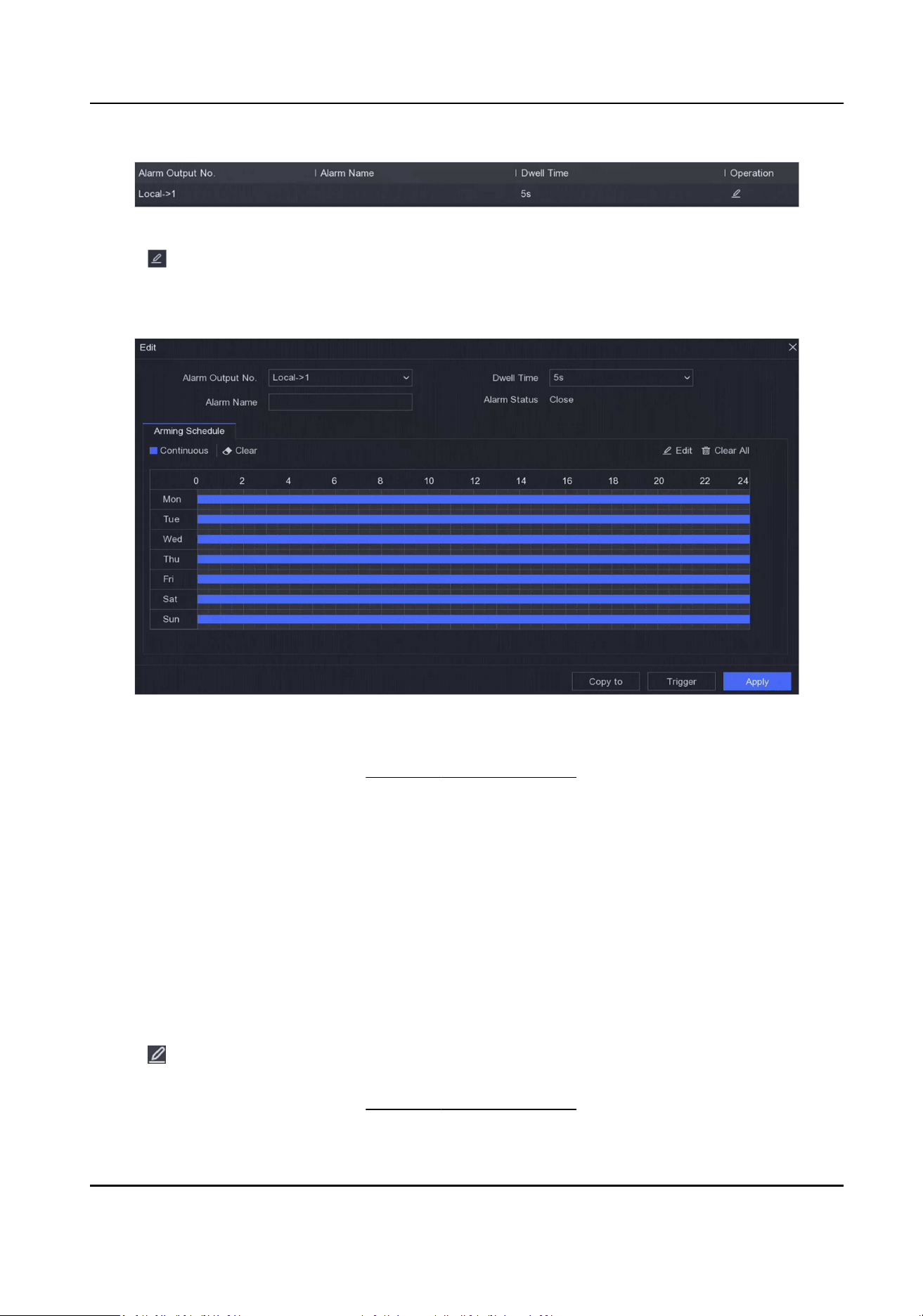
Figure 6-17 Alarm Output
2.
Click of a desired alarm output.
3.
Customize Alarm Name.
4.
Select Dwell Time.
Figure 6-18 Edit Alarm Output
5.
Set Sengs as Input to enable the funcon.
6.
Set the arming schedule. Refer to Congure Arming Schedule for details.
7.
Click Apply.
Flashing Light Alarm Output
When light and audio alarm camera is connected, you can set the ashing me, ashing frequency,
and arming schedule of the ashing light alarm.
Before You Start
Light and audio alarm camera is connected.
Steps
1.
Go to Conguraon → Event → Normal Event → Flashing Light Alarm Output.
2.
Click for any row.
3.
Set the Flashing Time and Flashing Frequency.
4.
Set the arming schedule. Refer to Congure Arming Schedule for details.
Network Video Recorder User Manual
66

5.
ClickSave.
Audio Alarm Output
When light and audio alarm camera is connected, you can set the parameters and arming schedule
of the audio alarm.
Before You Start
Light and audio alarm camera is connected.
Steps
1.
Go to Conguraon → Event → Normal Event → Flashing Light Alarm Output.
2.
Click for any row.
3.
Select the Audio Type as Alarm Sound, Prompt Sound, or Custom Audio.
Note
●
When you select the Alarm Sound, you also need to select the alarm sound type.
●
When you select the Alarm Sound, you also need to upload the custom audio, enter the audio
name and select the uploaded audio in the drop-down box of Custom Audio.
4.
Set the Alarm Times and Sound Volume.
5.
Set the arming schedule. Refer to Congure Arming Schedule for details.
6.
ClickSave.
Excepon
Excepon events can be congured to take the event hint in the live view window and trigger
alarm outputs and linkage acons.
Steps
1.
Go to Conguraon → Event → Normal Event → Excepon .
2.
Congure event hint. When the set events occur, you will receive hints in alarm center.
1) Enable Event Hint.
2) Select events to hint. Choose from:
●
Click of Event Hint Conguraon to select events.
●
Click in the upper-right corner of local menu to enter alarm center to select events.
3.
Select Excepon Type to set its linkage acons.
Network Video Recorder User Manual
67
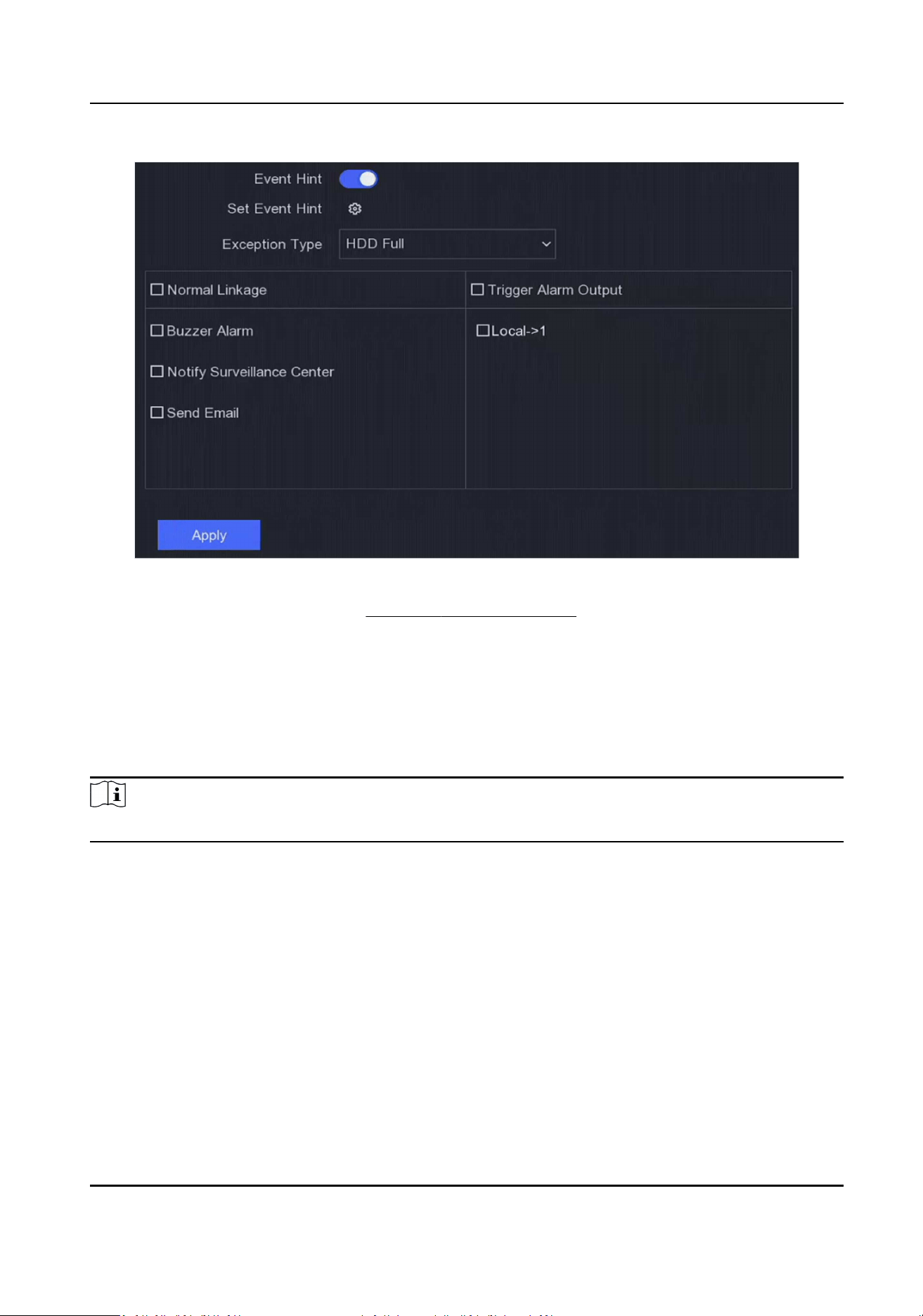
Figure 6-19 Excepons
4.
Set the arming schedule. Refer to Congure Arming Schedule for details.
5.
Click Apply.
6.6.2 Perimeter Protecon
Perimeter protecon includes line crossing detecon, intrusion detecon, region entrance
detecon, and region exing detecon.
Note
Perimeter protecon is only available for certain device models or camera models.
Line Crossing Detecon
Line crossing detecon detects people, vehicles, and objects crossing a set virtual line. The
detecon direcon can be set as bidireconal, from le to right or from right to le.
Steps
1.
Go to Conguraon → Event → Perimeter Protecon → Line Crossing .
2.
Set Camera.
3.
Select VCA Mode.
By NVR
Network Video Recorder User Manual
68

The event will be analyzed by NVR. The device can analyze videos that contain human and
vehicle. Only the target of selected type (human or vehicle) will trigger alarms, which can
reduce false alarms that are caused by other objects.
By Camera
The event will be analyzed by camera.
4.
Turn on Enable.
5.
Set the detecon rules and detecon areas.
1) Set Arming Area.
2) Set Direcon as A<->B, A->B, or A<-B.
A<->B
Only the arrow on the B side shows. An object crossing a congured line in both direcons
can be detected and trigger alarms.
A->B
Only an object crossing the congured line from the A side to the B side can be detected.
B->A
Only an object crossing the congured line from the B side to the A side can be detected.
3) Click Max. Size and draw a quadrilateral in the preview window to set the maximum draw
area size.
4) Click Min. Size and draw a quadrilateral in the preview window to set the minimum draw area
size.
5) Click Draw Area and draw a quadrilateral in the preview window by specifying four vertexes of
the detecon region.
6.
Adjust Sensivity. Sensivity allows you to calibrate how readily movement triggers the alarm. A
higher value results in the more readily to triggers moon detecon.
7.
Oponal: Set Detecon Target as Human or Vehicle to discard alarms which are not triggered
by human or vehicle.
Note
This funcon is only available for certain models.
8.
Set the arming schedule. Refer to Congure Arming Schedule for details.
9.
Set the linkage acons. Refer to Congure Alarm Linkage Acon for details.
10.
Click Apply.
Intrusion Detecon
Intrusion detecon funcon detects people, vehicles, or objects that enter and loiter in a pre-
dened virtual region.
Steps
1.
Go to Conguraon → Event → Smart Event → Intrusion .
2.
Set Camera.
Network Video Recorder User Manual
69

3.
Select VCA Mode.
By NVR
The event will be analyzed by NVR. The device can analyze videos that contain human and
vehicle. Only the target of selected type (human or vehicle) will trigger alarms, which can
reduce false alarms that are caused by other objects.
By Camera
The event will be analyzed by camera.
4.
Turn on Enable.
5.
Oponal: Check Save VCA Picture to save the captured pictures of VCA detecon.
6.
Set the detecon rules and detecon areas.
1) Set Arming Area. Up to 4 arming areas are selectable.
2) Adjust Time Threshold and Sensivity.
Sensivity
The size of the object that can trigger the alarm. The higher the value is, the more easily
the detecon alarm will be triggered. Its range is [1-100].
Time Threshold
Range [1s-10s], the threshold for the me of the object loitering in the region. When the
duraon of the object in the dened detecon area is longer than the set me, the alarm
will be triggered.
3) Oponal: Set Detecon Target as Human or Vehicle to discard alarms which are not triggered
by human body or vehicle.
4) Click Max. Size and draw a quadrilateral in the preview window to set the maximum draw
area size.
5) Click Min. Size and draw a quadrilateral in the preview window to set the minimum draw area
size.
6) Click Draw Area and draw a quadrilateral in the preview window by specifying four vertexes of
the detecon region.
7.
Set the arming schedule. Refer to
Congure Arming Schedule for details.
8.
Set the linkage acons. Refer to Congure Alarm Linkage Acon for details.
9.
Click Apply.
Region Entrance Detecon
Region entrance detecon funcon detects people, vehicles or other objects which enter a pre-
dened virtual region from the outside place, and some certain acons can be taken when the
alarm is triggered.
Steps
1.
Go to Conguraon → Event → Smart Event → Region Entrance .
2.
Set Camera.
3.
Select VCA Mode.
Network Video Recorder User Manual
70

By NVR
The event will be analyzed by NVR. The device can analyze videos that contain human and
vehicle. Only the target of selected type (human or vehicle) will trigger alarms, which can
reduce false alarms that are caused by other objects.
By Camera
The event will be analyzed by camera.
4.
Turn on Enable.
5.
Oponal: Check Save VCA Picture to save the captured pictures of VCA detecon.
6.
Set the detecon rules and detecon areas.
1) Set Arming Area. Up to 4 arming areas are selectable.
2) Adjust Sensivity. Sensivity: Range [0-100]. The higher the value is, the more easily the
detecon alarm can be triggered.
3) Oponal: Set Detecon Target as Human or Vehicle to discard alarms which are not triggered
by human body or vehicle.
4) Click Max. Size and draw a quadrilateral in the preview window to set the maximum draw
area size.
5) Click Min. Size and draw a quadrilateral in the preview window to set the minimum draw area
size.
6) Click Draw Area and draw a quadrilateral in the preview window by specifying four vertexes of
the detecon region.
7.
Set the arming schedule. Refer to Congure Arming Schedule for details.
8.
Set the linkage acons. Refer to Congure Alarm Linkage Acon for details.
9.
Click Apply.
Region Exing Detecon
Region exing detecon funcon detects people, vehicles or other objects which exit from a pre-
dened virtual region, and some certain acons can be taken when the alarm is triggered.
Steps
1.
Go to Conguraon → Event → Smart Event → Region Exing .
2.
Set Camera.
3.
Select VCA Mode.
By NVR
The event will be analyzed by NVR. The device can analyze videos that contain human and
vehicle. Only the target of selected type (human or vehicle) will trigger alarms, which can
reduce false alarms that are caused by other objects.
By Camera
The event will be analyzed by camera.
4.
Turn on Enable.
5.
Oponal: Check Save VCA Picture to save the captured pictures of VCA detecon.
Network Video Recorder User Manual
71

6.
Set the detecon rules and detecon areas.
1) Set Arming Area. Up to 4 arming areas are selectable.
2) Adjust Sensivity. Sensivity: Range [0-100]. The higher the value is, the more easily the
detecon alarm can be triggered.
3) Oponal: Set Detecon Target as Human or Vehicle to discard alarms which are not triggered
by human body or vehicle.
4) Click Max. Size and draw a quadrilateral in the preview window to set the maximum draw
area size.
5) Click Min. Size and draw a quadrilateral in the preview window to set the minimum draw area
size.
6) Click Draw Area and draw a quadrilateral in the preview window by specifying four vertexes of
the detecon region.
7.
Set the arming schedule. Refer to Congure Arming Schedule for details.
8.
Set the linkage acons. Refer to Congure Alarm Linkage Acon for details.
9.
Click Apply.
6.6.3 Facial Recognion
Facial recognion is the funcon that compares a captured face (in image or video stream) with
those in face picture libraries and returns its identy informaon if the face is recognized. Based on
facial feature of human being, facial recognion rst checks if human face exists in the input image
or video stream. If there is a human face, the funcon compares the face data (such as posion,
size, and facial feature) with those in current face picture libraries to idenfy the person.
Note
This funcon is only available for certain models.
Face Capture
Face capture detects human faces appearing in the scene. Linkage acons can be triggered when a
human face is detected.
Steps
1.
Go to Conguraon → Event → Face Recognion → Face Capture .
Network Video Recorder User Manual
72

Figure 6-20 Face Capture
2.
Select Camera.
3.
Turn on Enable.
4.
Adjust Sensivity.
Sensivity
The higher the value is, the more easily the defocus image can trigger the alarm.
5.
Set the arming schedule. Refer to Congure Arming Schedule for details.
6.
Set the linkage acons. Refer to Congure Alarm Linkage Acon for details.
7.
Click Apply.
Face Picture Comparison
Face picture comparison compares the detected face pictures with face pictures in the face picture
library. The device will trigger an alarm when comparison succeeded.
Before You Start
Ensure you have created at least one face picture library, and face pictures are added to the library.
Refer to Face Picture Library Management for operaon details.
Steps
1.
Go to Conguraon → Facial Recognion → Face Picture Comparison .
Network Video Recorder User Manual
73

Figure 6-21 Face Picture Comparison
2.
Select a camera.
3.
Turn on Enable.
4.
Select the face picture library (or libraries) in List Library Linkage.
5.
Set the face picture library similarity.
Similarity
Similarity value ranges from 0 to 100. Device will analyze the similarity between the detected
face picture and face pictures in the library. When the similarity reaches the threshold value,
the face picture comparison succeeded, and the face picture is recognized.
6.
Set the arming schedule. Refer to
Congure Arming Schedule for details.
7.
Set the linkage acons for Linkage Succeeded and Linkage Failed. Refer to Congure Alarm
Linkage Acon for details.
Linkage Succeeded
The device will perform linkage acons when the face picture comparison succeeded.
Linkage Failed
The device will perform linkage acons when the face picture comparison failed.
8.
Click Apply.
6.6.4 Non-Video Event
Congure non-video event.
Steps
1.
Go to Conguraon → Device Management → Non-Video Event.
2.
Select the device.
3.
Select the Alarm Content.
Network Video Recorder User Manual
74

4.
Set the arming schedule. Refer to Congure Arming Schedule for details.
5.
Set the linkage acons. Refer to Congure Alarm Linkage Acon for details.
6.
Click Apply。
6.6.5 Other Events
Thermal Camera Detecon
The device supports the event detecon modes of thermal network cameras: re detecon,
temperature detecon, etc. You can congure the arming schedule and linkage acons of the
selected event.
Before You Start
Add a thermal network camera to your device and make sure the camera is acvated.
Steps
1.
Go to Conguraon → Event → Other Events .
2.
Select a thermal camera detecon event.
3.
Set Camera.
4.
Set the arming schedule. Refer to Congure Arming Schedule for details.
5.
Set the linkage acons. Refer to Congure Alarm Linkage Acon for details.
6.
Click Apply.
6.6.6 Congure Arming Schedule
Steps
1.
Click Arming Schedule.
2.
Choose one day of a week and set the me segment. Up to eight me periods can be set within
each day.
Note
Time periods shall not be repeated or overlapped.
Network Video Recorder User Manual
75

Figure 6-22 Set Arming Schedule
3.
Click Apply.
6.6.7 Congure Alarm Linkage Acon
Congure Alarm Pop-up Window
When an alarm is triggered, the local monitor displays in full screen the video image from the
alarming channel congured for full screen monitoring. And when the alarm is triggered
simultaneously in several channels, you must congure the auto-switch dwell me.
Steps
1.
Go to Conguraon → System → Live View → General .
2.
Set the event output and dwell me.
Alarm Pop-up Output
Select the output to show event video.
Alarm Pop-up Delay
Set the me in seconds to show alarm event image. If alarms are triggered simultaneously in
several channels, their full-screen images will be switched at an interval of 10 seconds
(default dwell me).
3.
Click Linkage Acon of the alarm detecon.
4.
Select Alarm Pop-up Window alarm linkage acon.
5.
Select the channel(s) in Trigger Channel sengs you want to make full screen monitoring.
Note
Auto-switch will terminate once the alarm stops and back to the live view interface.
Network Video Recorder User Manual
76

Congure Buzzer Alarm
The audio warning enables the video recorder to trigger an audible beep when an alarm is
detected.
Steps
1.
Go to Conguraon → System → Live View → General .
2.
Turn on Audio, and set Volume.
3.
Go to Linkage Acon interface of the alarm detecon.
4.
Select Buzzer Alarm linkage acon.
Nofy Surveillance Center
The video recorder can send an excepon or alarm signal to the remote alarm host when an event
occurs. The alarm host refers to the computer installed with client soware (e.g., iVMS-4200,
iVMS-5200).
Steps
1.
Go to Conguraon → Network → General → More Sengs .
2.
Set Alarm Host IP and Alarm Host Port.
3.
Go to Linkage Acon interface of the alarm detecon.
4.
Select Nofy Surveillance Center.
Congure Email Linkage
The video recorder can send an email with alarm informaon to a user or users when an alarm is
detected.
Steps
1.
Go to Conguraon → Network → Email .
2.
Congure the sengs.
3.
Go to Linkage Acon interface of the alarm detecon.
4.
Select Send Email as alarm linkage acon.
Trigger Alarm Output
The alarm output can be triggered by the normal and smart events.
Steps
1.
Go to Linkage Acon interface of the alarm input or event detecon.
2.
Click Trigger Alarm Output.
3.
Select the alarm outputs to trigger.
Network Video Recorder User Manual
77

4.
Go to Conguraon → Event → Normal Event → Alarm Output .
5.
Select an alarm output item from the list. Refer to Alarm Output for details.
Congure PTZ Linkage
Video recorder can trigger the PTZ acons (e.g., call preset/patrol/paern) when the alarm event,
or VCA detecon events occur.
Steps
1.
Go to Linkage Acon interface of the alarm input or VCA detecon.
2.
Select PTZ Linkage.
3.
Select the camera to perform the PTZ acons.
4.
Select the preset/patrol/paern No. to call when the alarm events occur.
Figure 6-23 PTZ Linkage
Note
You can set one PTZ type only for the linkage acon each me.
6.7 Intelligent Search
6.7.1 AcuSearch
Enable AcuSearch funcon for selected channels.
Steps
1.
Go to Conguraon → Intelligent Search → Acu Search .
2.
Turn on Enable.
3.
Select the channels on which you want to enable the AcuSearch funcon.
4.
Click Apply.
Note
You can perform AcuSearch in playback interface. For details, please refer to Normal Playback
and Slice Playback .
Network Video Recorder User Manual
78

6.8 Recording Management
6.8.1 Congure Recording Schedule
Video recorder will automacally start/stop recording according to the congured schedule.
Congure Connuous Recording
Steps
1.
Go to Conguraon → Record → Parameter .
2.
Set the connuous main stream/sub-stream recording parameters for the camera.
3.
Go to Conguraon → Record → Schedule .
4.
Select recording type as Connuous.
Congure Event Recording
You can congure the recording triggered by the normal event or smart event.
Steps
1.
Go to Conguraon → Event .
2.
Congure the event detecon and select the cameras to trigger the recording when event
occurs.
3.
Go to Conguraon → Record → Parameter .
4.
Set the connuous main stream/sub-stream recording parameters for the camera.
5.
Go to Conguraon → Record → Schedule .
6.
Select recording type as Event.
Edit Schedule
Steps
1.
Go to Conguraon → Record → Schedule .
Network Video Recorder User Manual
79

Figure 6-24 Recording Schedule
Connuous
Connuous recording.
Event
Recording triggered by all event triggered alarms.
2.
Select a camera in Camera No.
3.
Turn on Enable.
4.
Congure the recording schedule.
1) Click Edit.
2) Select a day to congure in Weekday.
3) To set an all-day recording schedule, check All Day and select schedule Type.
4) To set other schedules, uncheck All Day and set Start/End me and schedule Type.
Note
Up to 8 periods can be congured for each day. And the me periods cannot be overlapped
with each other.
5) Click OK to save the sengs and go back to upper level menu.
Note
You can also select schedule type as Connuous or Event, and drag the cursor on the desired
period to draw a colored bar.
5.
Click Advanced to set advanced parameters.
Record Audio
Audio will be record to the video le.
Pre-Record
Network Video Recorder User Manual
80

The me you set to record before the scheduled me or event. For example, when an alarm
triggers the recording at 10:00, and if you set the pre-record me as 5 seconds, the camera
records at 9:59:55.
Post-Record
The me you set to record aer the event or the scheduled me. For example, when an
alarm triggered recording ends at 11:00, and if you set the post-record me as 5 seconds, it
records ll 11:00:05.
Stream Type
Main stream and sub-stream are selectable for recording. When you select sub-stream, you
can record for a longer me with the same storage space.
Video/Picture Expiry Time
The expiry me is period for a recorded le to be kept in the HDD. When the deadline is
reached, the le will be deleted. If you set the expiry me to 0, the le will not be deleted.
The actual keeping me for the le should be determined by the capacity of the HDD.
6.
Click OK to save the advanced sengs.
7.
Click Apply.
6.8.2 Congure Recording Parameter
Steps
1.
Go to Conguraon → Record → Parameter to congure camera main stream and sub-stream
parameters.
2.
Congure recording parameters.
Main Stream
Main stream refers to the primary stream that aects data recorded to the hard disk drive
and will directly determine your video quality and image size. Comparing with the sub-
stream, the main stream provides a higher quality video with higher resoluon and frame
rate.
●
Main Stream (Connuous) refers to the main stream of normal recording.
●
Main Stream (Event) refers to the main stream of event recording.
Sub-Stream
Sub-stream is a second codec that runs alongside the mainstream. It allows you to reduce the
outgoing internet bandwidth without sacricing your direct recording quality. Sub-stream is
oen exclusively used by smartphone applicaons to view live video. Users with limited
internet speeds may benet most from this seng.
Stream Type
You can choose to include video and audio or only video in the recording.
Resoluon
Network Video Recorder User Manual
81

Image resoluon is a measure of how much detail a digital image can hold: the greater the
resoluon, the greater the level of detail. Resoluon can be specied as the number of pixel-
columns (width) by the number of pixel-rows (height), for example, 1024 × 768.
Bitrate Type
●
Variable bitrate: The bitrate would be adjusted based on dierent scenarios, which leads to
higher ulizaon of network bandwidth, thus saving storage space. You can set 6 levels of
Video Quality. If you select H.265 as Video Encoding format, the system will adopt H.265
Pro encoding.
●
Constant bitrate: Encode at the maximum bitrate. Video Quality is not adjustable.
Frame Rate
Frame rate refers to how many frames are captured each second. A higher frame rate is
advantageous when there is movement in the video stream, as it maintains image quality
throughout.
Max. Bitrate Mode
●
General: Fixed-value parameters are available for selecon.
●
Custom: Customize the value of the maximum bitrate.
Video Encoding
Select the video encoding format. The opons are determined by the connected camera.
Enable H.265+
The H.265+ mode helps to ensure the high video quality with a lowered bitrate. It can
eecvely reduce the need of bandwidth and HDD storage space.
3.
Click Apply.
6.8.3 Storage Device
Inialize HDD
If it is the rst me you use your HDD, please inialize it aer it is installed.
Before You Start
Install at least an HDD to your video recorder.
Steps
1.
Go to Conguraon → Record → Storage .
2.
Select an HDD.
3.
Click Init.
Repair Database
Repair an HDD that with error in database. Please operate it with the help of professional
technical support.
Network Video Recorder User Manual
82

Add Network Disk
You can add the allocated NAS or IP SAN disk to the video recorder, and use it as a network HDD.
Steps
1.
Go to Conguraon → Record → Storage .
2.
Click Add.
3.
Set NetHDD.
4.
Set Type as NAS or IPSAN.
5.
Enter NetHDD IP address.
6.
Click to search the available disks.
Figure 6-25 Add NetHDD
7.
Select NAS disk from the list, or manually enter the directory in NetHDD Directory.
8.
Click OK.
Note
Up to 8 TB storage capacity is allowed for each network disk.
Result
The added network disks will be displayed in the storage device list.
Network Video Recorder User Manual
83

6.8.4 Congure Storage Mode
Congure HDD Quota
Each camera can be congured with an allocated quota for storing videos.
Steps
Note
This funcon is only available for certain models.
1.
Go to Conguraon → Record → Storage Mode .
2.
Select a camera to set quota in Camera.
3.
Enter the storage capacity in Record Capacity.
Note
When the quota capacity is set to 0, all cameras will use the total capacity of HDD for videos and
pictures.
4.
Click Apply.
5.
Restart the video recorder to acvate the new sengs.
6.8.5 Advanced Sengs
Steps
1.
Go to Conguraon → Record → Advanced .
2.
Congure the parameters as your desire.
Overwrite
●
Disable: When the HDD is full, video recorder will stop wring.
●
Enable: When hard drive is full, video record will connue to write new les by deleng the
oldest les.
Save Camera VCA Data
Camera VCA data will be saved so that you can search it.
Note
Disabling Save Camera VCA Data will delete the exisng Dual-VCA and moon detecon
informaon, and stop analyzing and storing Dual-VCA and moon detecon informaon.
Alarm Storage
When the HDD free space is not enough, you can disable it to save space, but your device will
stop storing alarm informaon.
Picture Storage
Network Video Recorder User Manual
84

When the HDD free space is not enough, you can disable it to save space, but your device will
stop storing pictures.
6.9 Face Picture Library Management
Face picture library is mainly used for face picture storage and face picture comparison.
Note
The secon is only available for certain models.
6.9.1 Add a Face Picture Library
Face picture library is used to store face pictures, it is essenal for face picture comparison.
Steps
1.
Go to Conguraon → Face Picture Library .
2.
Enter the admin password for authorizaon.
3.
Click Add.
4.
Enter the face picture library name.
5.
Click Add.
What to do next
Aer a face picture library is added, you can edit its name, delete it, or upload face pictures to it.
6.9.2 Upload Face Pictures to the Library
You can upload a single face picture or import mulple face pictures to the library.
Before You Start
Ensure you have created a face picture library and enabled face picture comparison.
Steps
1.
Go to Conguraon → Face Picture Library .
2.
Find the face picture library that you are going to upload face pictures, and click
.
3.
Click Add.
4.
Import picture(s).
Add one face picture to the library.
Add mulple face pictures to the library.
Network Video Recorder User Manual
85

Note
●
Only JPG and JPEG formats are supported.
●
Each picture size should be less than 1 MB.
●
The picture resoluon shall be between 80 × 80 and 1920 × 1080.
Network Video Recorder User Manual
86

Chapter 7 Maintenance
7.1 Restore Default
Steps
1.
Click at the upper-right corner.
2.
Select the restoring type.
Simple Restore
Restore all parameters, except the network (including IP address, subnet mask, gateway,
MTU, NIC working mode, default route, server port, etc.) and user account parameters, to the
factory default sengs.
Factory Defaults
Restore all parameters to the factory default sengs.
Restore to Inacve
Restore the device to the inacve status, and leave all sengs unchanged except restoring
user accounts.
3.
Click Yes. The device will reboot automacally.
7.2 Search Log
The operaon, alarm, excepon and informaon of video recorder can be stored in logs, which can
be viewed and exported at any me.
Steps
1.
Click
at the upper-right corner.
2.
Click More.
3.
Click Log Informaon.
4.
Set the search condions.
5.
Click Search.
7.3 System Service
Steps
1.
Click at the upper-right corner.
2.
Click More.
3.
Click System Service.
4.
Congure the parameters as your desire.
RTSP
Network Video Recorder User Manual
87

You can specically secure the stream data of live view by seng the RTSP authencaon.
RTSP Authencaon
Two authencaon types are selectable, if you select digest, only the request with digest
authencaon can access the video stream by the RTSP protocol via the IP address. For
security reasons, it is recommended to select digest as the authencaon type.
ISAPI
ISAPI (Internet Server Applicaon Programming Interface) is an open protocol based on HTTP,
which can realize the communicaon between the system devices (e.g., network camera,
NVR, etc.). The video recorder is used as a server, the system can nd and connect the video
recorder.
HTTP
The admin user account can disable the HTTP service from the GUI or the web browser. Aer
the HTTP is disabled, all the related services, including ISAPI and ONVIF, will terminate as
well.
HTTP Authencaon
If you need to enable the HTTP service, you can set the HTTP authencaon to enhance the
access security. Two authencaon types are selectable. For security reasons, it is
recommended to select digest as the authencaon type.
Camera Added Detecon
The funcon detects the network camera status. If the network camera has been added by
another video recorder, the network camera status will show as in Online Device list.
IOT Monitoring
Aer enabled, the IoT channel will be used for listening.
5.
Click Apply.
7.4 Buzzer Switch
You can enable or disable buzzer with alarm linkage or exceponal linkage.
Steps
1.
Click at the upper-right corner.
2.
Click More.
3.
Go to Buzzer Switch.
4.
Turn on or turn o Enable.
Network Video Recorder User Manual
88

7.5 Device Maintenance
7.5.1 Schedule Reboot
The device will automacally restart according to the schedule.
Steps
1.
Click at the upper-right corner.
2.
Click More.
3.
Go to Device Maintenance → Schedule Reboot .
4.
Turn on Enable.
5.
Set the reboot schedule.
6.
Click Apply.
7.5.2 Camera Upgrade
Upgrade the camera(s) in the added device list.
Steps
1.
ClickMaintenance( ) → More → Deice Maintenance → Camera Upgrade.
2.
Click Check for Updates.
3.
Upgrade camera.
-
Select the channel to upgrade, and click the Upgrade on the right.
-
Click Quick Upgrade to upgrade all channels that have updates.
7.5.3 Device Status
You can mute the selected channel(s).
Steps
1.
Click
at the upper-right corner.
2.
Click More.
3.
Go to Device Maintenance → Device Status .
4.
In the Mute and Not Disturb column, check the corresponding channel(s).
Result
The selected channel(s) will be muted.
7.5.4 Time Sync Diagnosis
View me sync informaon and enable me sync excepon detecon.
Network Video Recorder User Manual
89

Steps
1.
Click at the upper-right corner.
2.
Click More.
3.
Go to Device Maintenance → Time Sync Diagnosis .
View the current me sync informaon.
4.
Click Time Sync Conguraon.
5.
Turn on Enable Time Sync Excepon Detecon.
Note
●
Supports detecon of mulple me sync sources. If mulple me sync sources are detected,
you need to turn o unnecessary me sync sources in me, otherwise it may cause device
me changes, which will aect the recording.
●
Supports RTC baery detecon. If RTC baery is running out, device me excepon will occur,
which may cause video loss or incorrect recording me. Please change the buon cell baery
on the mainboard and sync me again.
6.
Click OK.
7.5.5 Picture Buer Enhancement
Aer the alarm picture buer enhancement mode is enabled, the receiving and sending buers of
the alarm picture will be improved when the device is started, which can prevent image loss.
Steps
1.
Click at the upper-right corner.
2.
Click More.
3.
Go to Device Maintenance → Picture Buer Enhancement .
4.
Turn on Enable.
Note
Aer enabling Picture Buer Enhancement, 2K/4K output will be disabled and the device would
be restarted.
7.6 Upgrade
Warning
Do not shutdown or turn o the power during upgrade.
Network Video Recorder User Manual
90

7.6.1 Local Upgrade
Before You Start
Store the upgrade rmware to a backup device, and connect it to your device.
Steps
1.
Click at the upper-right corner.
2.
Click .
3.
Click Local Upgrade.
4.
Select a backup device in Device Name.
5.
Select the upgrade rmware.
6.
Click Upgrade. Your device will reboot automacally.
7.6.2 Online Upgrade
Upgrade the device with the latest online rmware.
Before You Start
Ensure Hik-Connect is enabled and properly congured. Refer to Hik-Connect for details.
Steps
1.
Click at the upper-right corner.
2.
Click .
3.
Go to Online Upgrade .
4.
Download the latest rmware.
Auto Download The will automacally check and download the latest rmware.
Test Upgrade Click Test Upgrade to manually check and download the latest rmware.
5.
Upgrade your device if a new rmware version is available. The device will reboot automacally.
Network Video Recorder User Manual
91

Chapter 8 Alarm
When events occur, you can view their details in alarm center.
8.1 Set Event Hint
Select the events to hint in alarm center.
Steps
1.
Click at the upper-right corner.
2.
Select event type as your desire.
3.
Click and select events to hint.
4.
Click OK.
When the selected events occur, the alarm informaon will be displayed in (locang at the
upper-right corner of local menu).
8.2 View Alarm in Alarm Center
Steps
1.
Click at the upper-right corner of local menu.
2.
Select event type to view as your desire.
Network Video Recorder User Manual
92
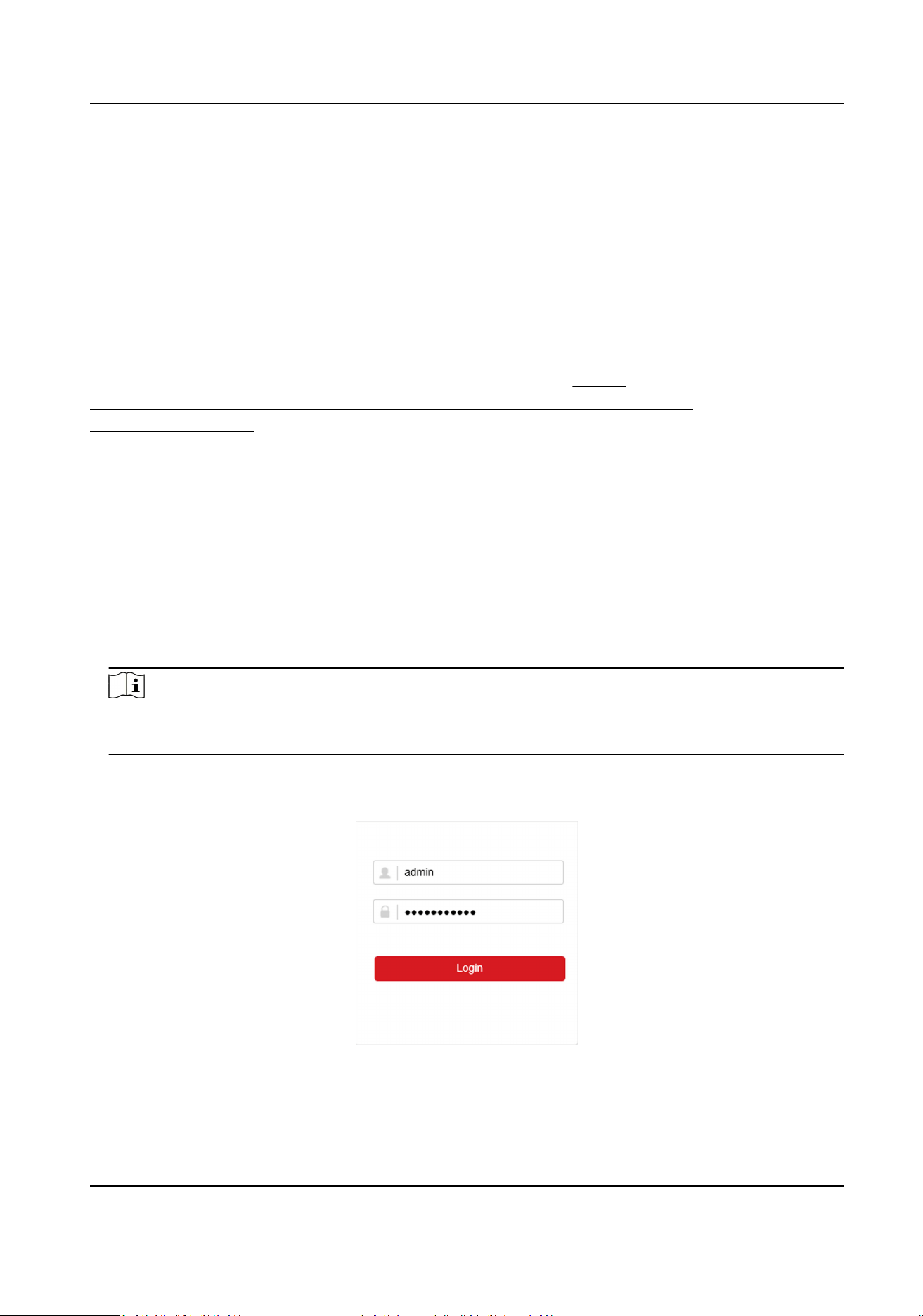
Chapter 9 Web Operaon
9.1 Introducon
You can get access to the video recorder via web browser.
You may use one of the following listed web browsers: Internet Explorer 11.0, Apple Safari, Mozilla
Firefox, and Google Chrome. The supported resoluons include 1024×768 and above.
For certain models, you will have to download a web component plug-in, and install it. Otherwise,
a few funcons would be unavailable. The download address is hp://
hikdownload.ys7.com/web/webplugin/windows/WebComponents/standard/
WebComponents.exe .
9.2 Login
You shall acknowledge that the use of the product with Internet access might be under network
security risks. For avoidance of any network aacks and informaon leakage, please strengthen
your own protecon. If the product does not work properly, please contact with your dealer or the
nearest service center.
Steps
1.
Open web browser, input the IP address of the video recorder and then press Enter.
Note
If you have changed HTTP port, enter hp://IP address:HTTP port in address bar. E.g., hp:
192.168.1.64:81.
2.
Enter user name and password in the login interface.
3.
Click Login.
Figure 9-1 Login
4.
Follow the installaon prompts to install the plug-in.
Network Video Recorder User Manual
93
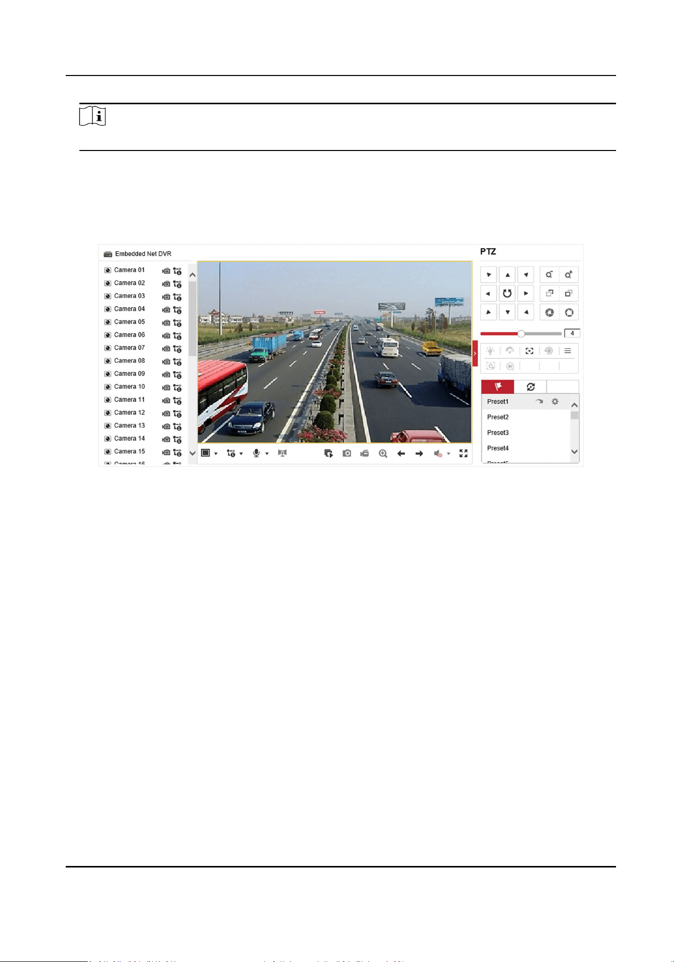
Note
You may have to close the web browser to nish the installaon of the plug-in.
9.3 Live View
Aer login, live view interface shows.
Figure 9-2 Live View
9.4 Playback
Click Playback to enter playback interface.
Network Video Recorder User Manual
94
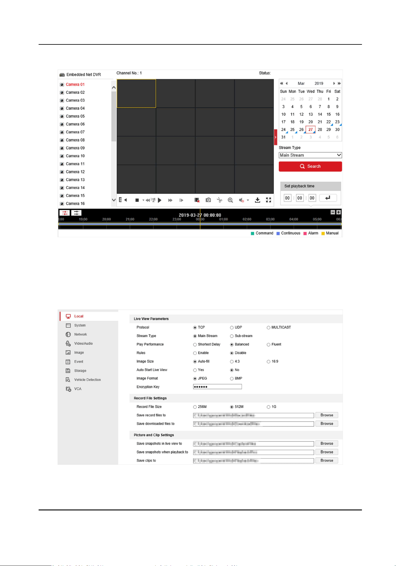
Figure 9-3 Playback
9.5 Conguraon
Click Conguraon to enter conguraon interface.
Figure 9-4 Conguraon
Network Video Recorder User Manual
95
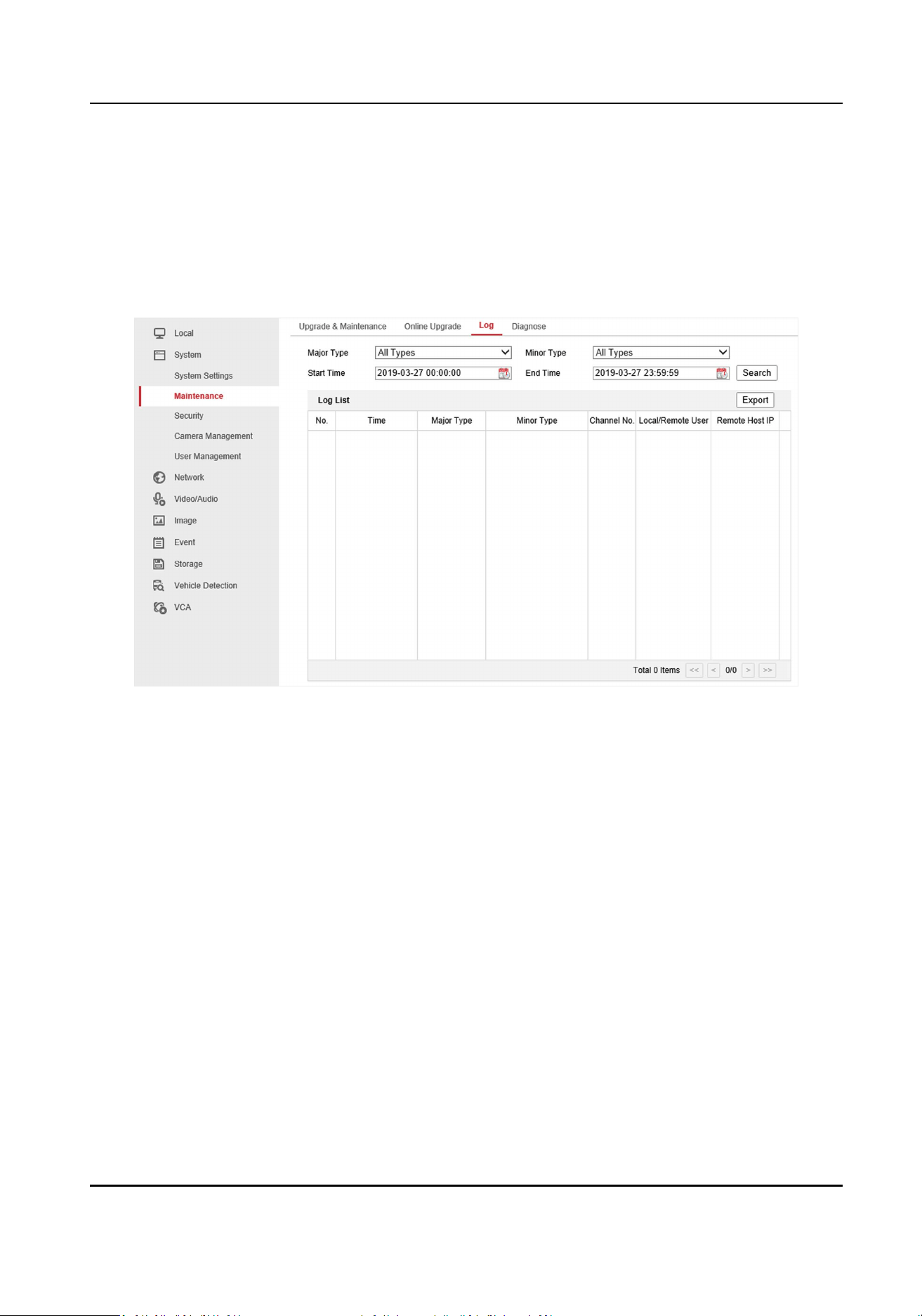
9.6 Log
Steps
1.
Go to Maintenance → System → Maintenance → Log .
2.
Set the search condions.
3.
Click Search.
Figure 9-5 Log
Network Video Recorder User Manual
96

Chapter 10 Appendix
10.1 Glossary
Dual-Stream
Dual-stream is a technology used to record high resoluon video locally while transming a
lower resoluon stream over the network. The two streams are generated by the DVR, with the
main stream having a maximum resoluon of 1080P and the sub-stream having a maximum
resoluon of CIF.
DVR
Acronym for Digital Video Recorder. A DVR is device that is able to accept video signals from
analog cameras, compress the signal and store it on its hard drives.
HDD
Acronym for Hard Disk Drive. A storage medium which stores digitally encoded data on plaers
with magnec surfaces.
DHCP
Dynamic Host Conguraon Protocol (DHCP) is a network applicaon protocol used by devices
(DHCP clients) to obtain conguraon informaon for operaon in an Internet Protocol
network.
HTTP
Acronym for Hypertext Transfer Protocol. A protocol to transfer hypertext request and
informaon between servers and browsers over a network.
PPPoE
PPPoE, Point-to-Point Protocol over Ethernet, is a network protocol for encapsulang Point-to-
Point Protocol (PPP) frames inside Ethernet frames. It is used mainly with ADSL services where
individual users connect to the ADSL transceiver (modem) over Ethernet and in plain Metro
Ethernet networks.
DDNS
Dynamic DNS is a method, protocol, or network service that provides the capability for a
networked device, such as a router or computer system using the Internet Protocol Suite, to
nofy a domain name server to change, in real me (ad-hoc) the acve DNS conguraon of its
congured hostnames, addresses or other informaon stored in DNS.
Hybrid DVR
A hybrid DVR is a combinaon of a DVR and NVR.
NTP
Acronym for Network Time Protocol. A protocol designed to synchronize the clocks of
computers over a network.
Network Video Recorder User Manual
97

NTSC
Acronym for Naonal Television System Commiee. NTSC is an analog television standard used
in such countries as the United States and Japan. Each frame of an NTSC signal contains 525
scan lines at 60Hz.
NVR
Acronym for Network Video Recorder. An NVR can be a PC-based or embedded system used for
centralized management and storage for IP cameras, IP Domes and other DVRs.
PAL
Acronym for Phase Alternang Line. PAL is also another video standard used in broadcast
televisions systems in large parts of the world. PAL signal contains 625 scan lines at 50Hz.
PTZ
Acronym for Pan, Tilt, Zoom. PTZ cameras are motor driven systems that allow the camera to
pan le and right, lt up and down and zoom in and out.
USB
Acronym for Universal Serial Bus. USB is a plug-and-play serial bus standard to interface devices
to a host computer.
Network Video Recorder User Manual
98

UD37582B