
Technical Support and E-Warranty Certificate www.vevor.com/support
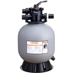
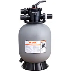
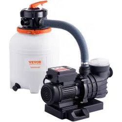
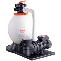
SAND FILTER
MODEL:25023BX/25033BX/25043BX/25053BX
We continue to be committed to provide you tools with competitive price.
"Save Half", " Half Price" or any other similar expressions used by us only represents an
estimate of savings you might benefit f rom buying certain tools with us compared to the major
top brands and doses not necessarily mean to cover all categories of tools offered by us. You
are kindly reminded to verify carefully when you are placing an order with us if you are
actually saving half in comparison with the top major brands.

- 1 -
MODEL:25023BX/25033BX/25043BX/25053BX
Have product questions? Need technical support? Please feel free to
contact us:
CustomerService@vevor.com
NEED HELP? CONTACT US!
This is t he original instruction, please read all manual instructions
carefully before operating. VEVOR reserves a clear interpretation of our
user manual. The appearance of the product shall be subject to the
product you received. Please forgive us that we won't inform you again if
there are any technology or software updates on our product.
SAND FILTER

- 2 -
FUNCTION
The filter uses special filter sand to remove dirt particles from pool water.
The filter sand is loaded into the filer tank and functions as the permanent
dirt-removing media. When the control valve is in the FILTER position, the
pool water, which contains suspended dirt particles, is pumped through
your piping system and is automatically directed by the patented filter
control valve to the top of the filter tank. As the pool water is pumped
through the filter, dirt particles are trapped by the sand bed and filtered out.
The cleaned pool water is returned from the bottom of the filter tank,
through the control valve, and back to the pool through the piping system.
This entire sequence is continuous and automatic and provides for total
recirculation of pool water through your filter and piping System. After a
period of time, the accumulated dirt in the filter causes a resistance to flow,
and the flow diminishes. This means it is time to clean your filter. With the
control valve in the BACKWASH position, the water flow is automatically
reversed through the filter so that it is directed to the bottom of the tank, up
through the sand, flushing the previously trapped dirt and debris out the
waste line. Once the filter is back-washed of dirt, set the control valve to
RINSE position and run the pump for about 1/2 to 1 minute, and then to the
filter to resume normal filtering.
NOTE: Turn the pump off before changing the valve position.
INSTALLATION
Only simple tools (screwdriver and wrenches), plus pipe sealant for plastic
adapters, are required to install and service the filter.
1.The filter should be placed on a level concrete slab, very firm ground, or
equivalent. Position the filter so that the piping connections and control
valve are convenient and accessible for operation and service.
2.Loading the sand media. Filter sand media is loaded through the top
opening of the filter.

- 3 -
a. Loosen the flange clamp and remove the filter control valve (if
previously installed).
b. Cap the internal pipe with a plastic cap to prevent sand from entering
it.
c. We recommend a filling tank approximately 1/2way with water to
provide a cushion effect when the filter sand is poured in. This helps
protect the under-drain laterals from excessive shock.
d. Carefully pour in the correct amount and grade of filter sand. (Be sure
the center pipe remains centered in the opening.) The sand surface
should be leveled and should come to about the middle of the filter
tank. Remove the plastic cap from the internal pipe.
3.Assemble the filter control valve to the filter tank.
a. Insert the filter control valve (with O ring in place) into the tank neck,
taking care that the center pipe slips into the hole in the bottom of the
valve.
b. Place two plastic clamps around the valve flange and tank flange and
tighten just enough so that the valve may not be rotated on the tank for
final positioning.
c. Carefully screw the pressure gauge (with the O ring in place) into the
tapped hole in the valve body. Do not over-tighten.
d.Connect the pump to the control valve opening marked PUMP. After
connections are made, tighten valve flange clamps with a screwdriver,
tapping around clamp with a screwdriver handle to help seat valve
flange clamp.
4.Make a return to the pool pipe connection to the control valve opening
marked RETURN and complete other necessary plumbing connections,
suction lines to pump, waste, etc.
5.Make electrical connections to the pump per pump instructions.
6.To prevent water leakage, be sure all pipe connections are tight.
- 4 -
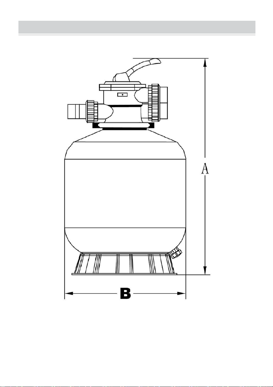
MAIN DIMENSION
- 5 -
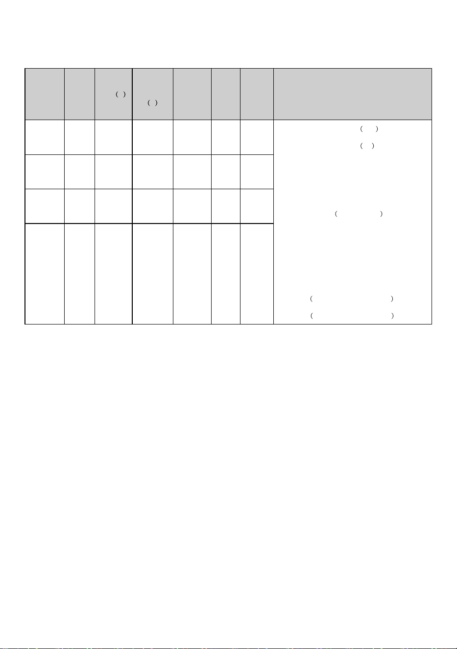
DIMENSION TABLE
Model Size
High A
Diameter
B
Valve
Port
Size
Sand Qmax Accessories
25023BX 16" 820mm 400mm 11/2"
1.Cylinder end locking ring
right 1PCS
2.Cylinder end locking ring
left 1PCS
3.Two-end threaded joint 3PCS
4.Single-end threaded joint 1PCS
5.Transparent single-end T-thread 1PCS
6.Pressure gauge
radial direction 1PCS
7.Screw three-piece set 2PCS
8.Teflon tape 1PCS
9.Locking nut 3PCS
10.T-joint 2PCS
11.O-ring 58 x 3.1 mm A-level rubber 3PCS
12.O-ring
50 x 3.1 mm A-level rub ber 3PCS
25033BX 19" 835mm 458mm 11/2"
25043BX 22" 855mm 506mm 11/2"
25053BX 24" 1095mm 600mm 11/2"
35GPM
45GPM
55GPM
65GPM
35kg
45kg
85kg
145kg

- 6 -
INSTALL/START-UP OF FILTER
1.Be sure the correct amount of filter media sand is in the tank and that all
connections have been made and are secure.
2.Depress the control valve handle and rotate to the BACKWASH position.
(To prevent damage to the control valve seal, always depress the handle
before turning.)
3.Prime and start the pump according to pump instructions (be sure all
suction and return lines are open), allowing the filter tank to fill with water.
Once water is flowing out of the waste line, run the pump for at least l
minute.The initial back-washing of the filter is recommended to remove
any impurities or fine sand particles in the sand media.
4.Turn the pump off and set the valve to the RINSE position. Start the
pump and operate until the water in the sight glass is clear, about 1/2 to l
minute. Turn the pump off and set the valve to FILTER position and
restart the pump. The filter is now operating in the normal filter mode,
filtering dirt particles from the pool water.
5.Adjust pool suction and return valves to achieve the desired flow. Check
the system and filter for water leaks and tighten connections, bolts, and
nuts, as required.
6.Note the initial pressure gauge reading when the filter is clean. (It will
vary from pool to pool depending upon the pump and general piping
system.) As the filter removes dirt and impurities from the pool water, the
accumulation in the filter will cause the pressure to rise and flow to
diminish. When the pressure gauge reading is 1.5 bar, higher than the
initial clean pressure you noted, it is time to backwash the filter (see
BACKWASH under filter and control valve functions).
NOTE: During the initial clean-up of the pool water, it may be necessary to
backwash frequently due to the unusually heavy initial dirt load in the
water.
- 7 -
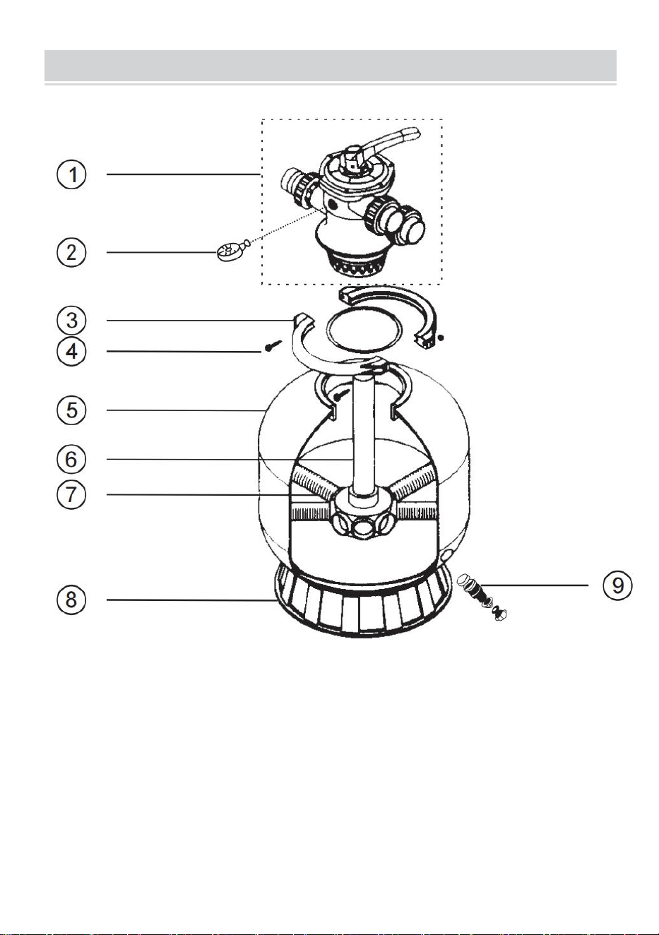
REPLACEMENT PARTS OF FILTER

- 8 -
Item
Part number
Description
1
MPV-01A
Valve
2
FT-03W-04-1
FT-03W-05
Pressure gauge with o ring
3
FT-01-003
Flange clamp
4
MPV-01W-10-1
MPV-01W-10-2
Screw with nut
5
FT-01-035
FT-01-036
FT-01-037
FT-01-038
FT-01-039
Ph350
PH400
PH450 Filter tank
PH500
PH600
6
MPV-03W-03
FT-01-017
Lateral assembly
with center pipe
7
FT-01-022
FT-01-023
PH350-PH400
PH450-PH600
Lateral
8
FT-01-008
FT-01-007
PH350-PH400
PH450-PH600
Filter
base
9
FT-01-010
Drain

- 9 -
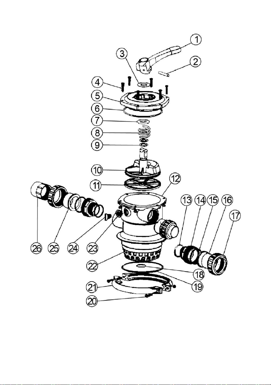
REPLACEMENT PARTS OF THE MULTIPORT VALVE
Item
Description
Qty
Part No
1
Handle
1
MPV-01-020
2
Pin handle
1
MPV-01W-1
3
Washer
1
MPV-01-006
4
Bolt with nut, lid
6
MPV-01W-02-1
MPV-01W-02-2
5
Lid assy
1
MPV-01-004
6
O'ring,lid
1
MPV-01W-03
7
Washer
1
MPV-01-007
8
Spring
1
MPV-01W-04
9
O'ring,rotor
2
MPV-01W-05
10
Rotor
1
MPV-01-005
11
Gasket,spider
1
MPV-01-015
12
Body-diffuser assy
1
MPV-01-001
13
O'ring,bulkhead
3
MPV-01W-06
14
Bulkhead fitting
3
MPV-03-004
15
O'ring,bulkhead
3
MPV-01W-7
16
Adaptor,bulkhead
2
MPV-01-010
17
Nut,bulkhead
3
MPV-01-009
18
O'ring,standpipe
1
MPV-01W-8
19
O'ring,filter
1
MPV-01W-9B
20
Bolt with nut,clamp
2
MPV-01W-10-1
MPV-01W-10-2
21
Flange clamp
2
FT-01-003
22
Over drain,diffuser
1
MPV-01-012
23
Nut,plug
1
MPV-01-014
24
Plug with o ring
1
MPV-01-013
FT-03W-05
25
Sight glass
1
MPV-01-017
26
Tricky set
1
MPV-01-018
- 10 -
- 11 -
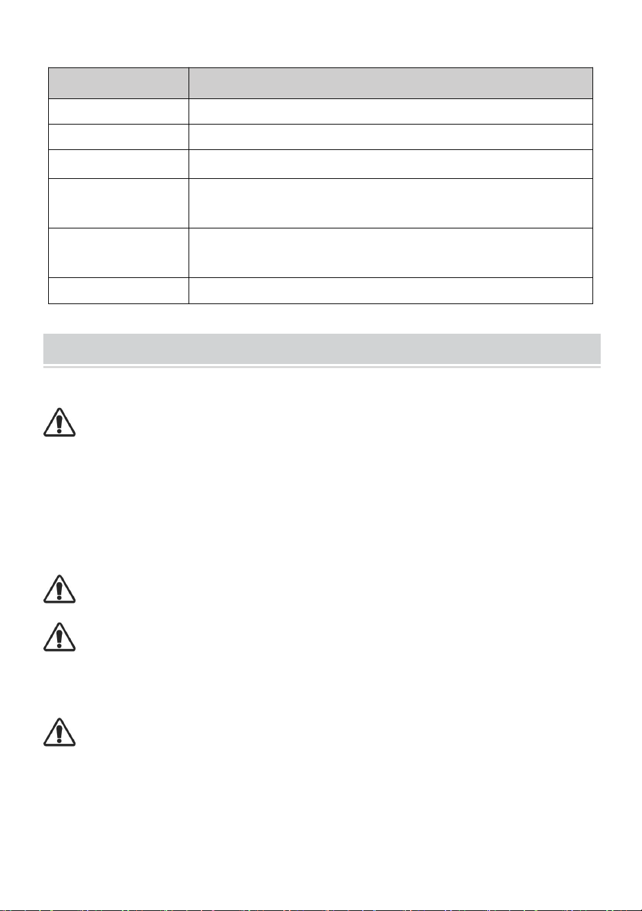
Valve Position
Function
FILTER
Normal Filtration and Vacuuming
BACKWASH
Cleaning Filter by reversing the flow
RINSE
Used after backwash to flush dirt from the valve
WASTE
By-passes filter, used for vacuuming to waste or lowering
the water level
RECIRCULATE
By-passes filter for circulating water to pool
CLOSED
Shuts off all flow to filter or pool
REPLACEMENT PARTS OF THE MULTIPORT VALVE
THIS FILTER OPERATES UNDER HIGH PRESSURE. WHEN ANY PART
OF THE CIRCULATING SYSTEM (e.g., CLAMP, PUMP, FILTER, VALVES,
ETC.) IS SERVICED, AIR CAN ENTER THE SYSTEM AND BECOME
PRESSURIZED. PRESSURIZED AIR CAN CAUSE THE LID OR VALVE TO
BE BLOWN OFF, WHICH CAN RESULT IN SEVERE INJURY, DEATH, OR
PROPERTY DAMAGE
TURN THE PUMP OFF BEFORE CHANGING THE VALVE POSITION.
TO PREVENT DAMAGE TO THE PUMP AND FOR PROPER OPERATION
OF THE SYSTEM, CLEAN THE PUMP STRAINER AND SKIMMER
BASKETS REGULARLY.
DO NOT UNSCREW THE SCREWS OFF LANGE CLAMP WHILE THE
PUMP IS RUNNING.

- 12 -
Made In China

- 13 -