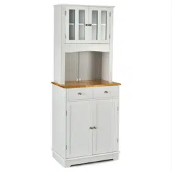

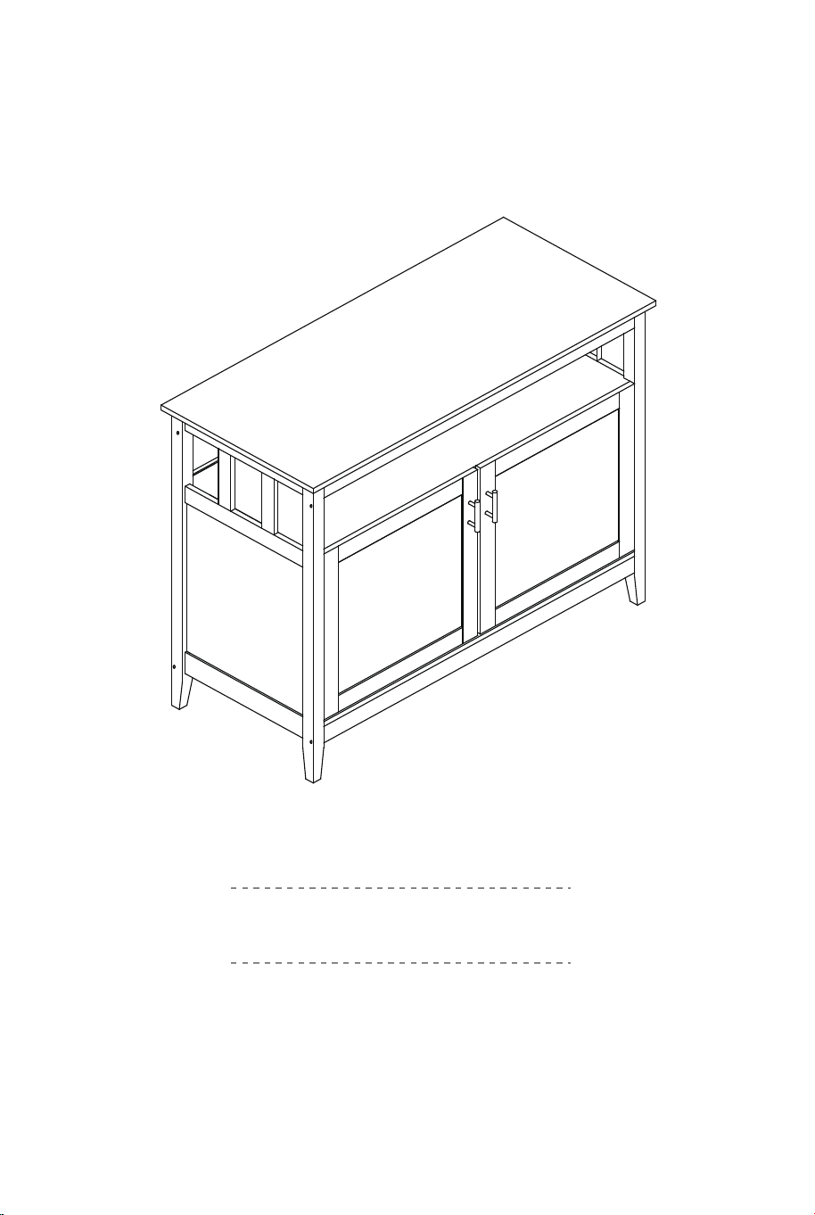
HW53869
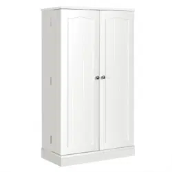
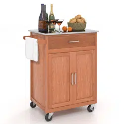
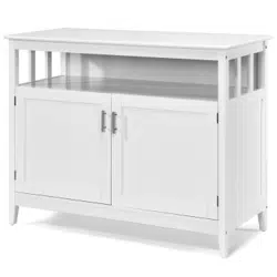
Kitchen Sideboard Cabinet
Meuble de Cuisine
THIS INSTRUCTION BOOKLET CONTAINS IMPORTANT SAFETY INFORMATION. PLEASE READ AND KEEP FOR FUTURE REFERENCE.
If you're having difficulty, our friendly
customer team is always here to help.
USA office: Fontana AUS office: Truganina
GBR office: Ipswich FRA office: Saint Vigor d'Ymonville
AUS:cs.au@costway.com
GBR:cs.uk@costway.com
FRA:cs.fr@costway.com
02 03
Before You Start
Please read all instructions carefully.
Retain instructions for future reference.
Separate and count all parts and hardware.
Read through each step carefully and follow the proper order.
We recommend that, where possible, all items are assembled near to the area in
which they will be placed in use, to avoid moving the product unnecessarily once
assembled.
Always place the product on a flat, steady and stable surface.
Keep all small parts and packaging materials for this product away from babies
and children as they potentially pose a serious choking hazard.
FR
Veuillez lire attentivement toutes les instructions.
Conservez les instructions pour vous y référer ultérieurement.
Vérifiez toutes les pièces et les accessoires.
Lisez attentivement chaque étape et suivez l’ordre correct.
Nous recommandons que, dans la mesure du possible, tous les produits
soient assemblés à proximité de la zone où ils seront utilisés, afin d’éviter tout
déplacement inutile du produit une fois assemblé.
Placez toujours le produit sur une surface plane et stable.
Conservez toutes les petites pièces de ce produit et les matériaux d’emballage
hors de portée des bébés et des enfants, car ils pourraient présenter un risque
d’étouffement.
Avant de Commencer
Kitchen Sideboard Cabinet
Meuble de Cuisine
EN
04 05
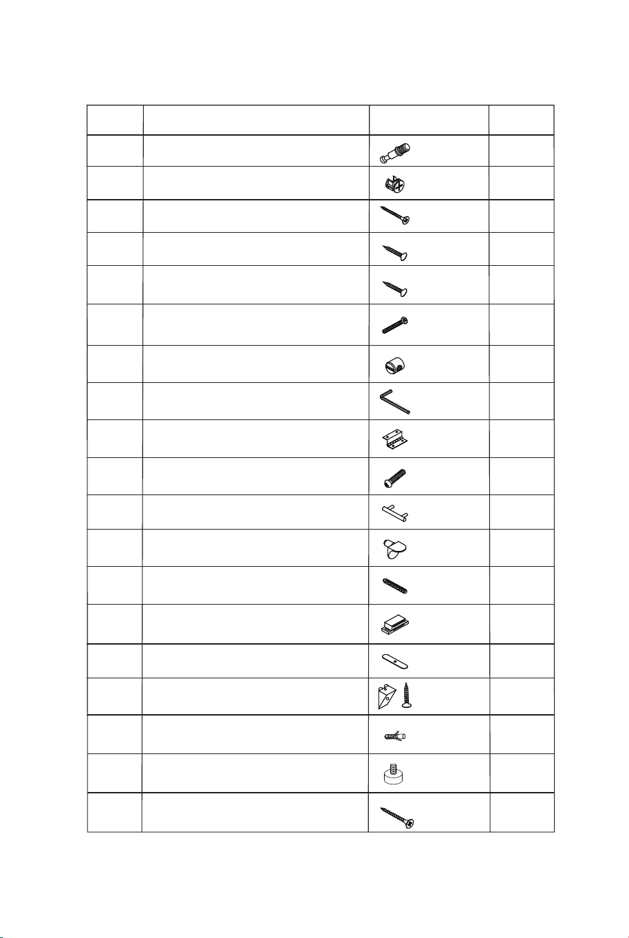
Hardware List / Liste des Accessoires
H
DESCRIPTION/DESCRIPTION
B
C
D
F
G
E
ITEM
/OBJET
PART/PIÈCE
QTY/
I
J
L
M
N
K
O
P
Q
x10
x9
x2
x18
x8
x8
x1
x4
x4
x2
x4
x28
x1
x2
x8
x2
Camlock / Verrou à came
Screw / Vis
Screw / Vis
Screw / Vis
Allen Head Bolt /
Boulon à tête Allen
Barrel Nut / Écrou de baril
Allen Wrench / Clé Allen
Hinge / Charnière
Handle Bolt / Boulon de poignée
Handle / Poignée
Shelf Pin / Goupille d'étagère
Wooden Dowel /
Cheville en bois
Magnetic Catch /
Loquet magnétique
Magnetic Bar /
Barre magnétique
Fixed Button / Bouton fixe
Plastic Anchor /
Ancrage en plastique
A
x10
Cam Bolt / Boulon à came
6x35mm
15x10mm
4x40mm
3x14mm
3x12mm
6x70mm
10x10mm
45mm
4x16mm
8x40mm
35x12x1mm
x4
R
Adjustable Leg Stud / Goujon de
pied réglable
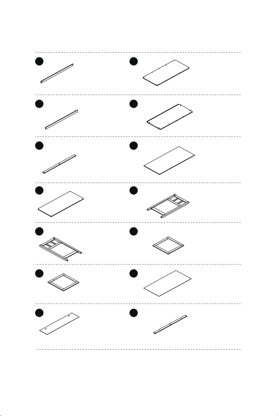
Part List / Liste des Pièces
Connect Rail
for Bottom
Panel / Rail de
connexion
pour panneau
inférieure
Connect Rail
for Shelf / Rail
de connexion
pour étagère
Front Connect
Rail for Top
Panel / Rail de
connexion
avant pour
panneau
supérieur
Adjustable
Shelf / Étagère
réglable
Right Side
Panel /
Panneau
latéral droit
Right Side
Panel / Porte
droite
Upper Back
Panel /
Panneau
arrière
supérieur
Bottom Panel
/ Panneau
inférieure
Shelf / Étagère
Top Panel
/ Panneau
supérieur
Left Side
Panel
/ Panneau
latéral gauche
Left Door
/ Porte gauche
Lower Back
Panel
/ Panneau
inférieure
arrière
Back Connect
Rail for Top
Panel / Rail de
connexion
arrière pour
panneau
supérieur
1 x2
2
x1
3 x1
4
x1
5 x1
6
x1
7 x1
8
x1
9 x1
10
x1
11
x1
12
x1
13
x1
14
x1
4x70mm
x2
Screw / Vis
S
04 05
Hardware List / Liste des Accessoires
H
DESCRIPTION/DESCRIPTION
B
C
D
F
G
E
ITEM
/OBJET
PART/PIÈCE
QTY/
I
J
L
M
N
K
O
P
Q
x10
x9
x2
x18
x8
x8
x1
x4
x4
x2
x4
x28
x1
x2
x8
x2
Camlock / Verrou à came
Screw / Vis
Screw / Vis
Screw / Vis
Allen Head Bolt /
Boulon à tête Allen
Barrel Nut / Écrou de baril
Allen Wrench / Clé Allen
Hinge / Charnière
Handle Bolt / Boulon de poignée
Handle / Poignée
Shelf Pin / Goupille d'étagère
Wooden Dowel /
Cheville en bois
Magnetic Catch /
Loquet magnétique
Magnetic Bar /
Barre magnétique
Fixed Button / Bouton fixe
Plastic Anchor /
Ancrage en plastique
A
x10
Cam Bolt / Boulon à came
6x35mm
15x10mm
4x40mm
3x14mm
3x12mm
6x70mm
10x10mm
45mm
4x16mm
8x40mm
35x12x1mm
x4
R
Adjustable Leg Stud / Goujon de
pied réglable
Part List / Liste des Pièces
Connect Rail
for Bottom
Panel / Rail de
connexion
pour panneau
inférieure
Connect Rail
for Shelf / Rail
de connexion
pour étagère
Front Connect
Rail for Top
Panel / Rail de
connexion
avant pour
panneau
supérieur
Adjustable
Shelf / Étagère
réglable
Right Side
Panel /
Panneau
latéral droit
Right Side
Panel / Porte
droite
Upper Back
Panel /
Panneau
arrière
supérieur
Bottom Panel
/ Panneau
inférieure
Shelf / Étagère
Top Panel
/ Panneau
supérieur
Left Side
Panel
/ Panneau
latéral gauche
Left Door
/ Porte gauche
Lower Back
Panel
/ Panneau
inférieure
arrière
Back Connect
Rail for Top
Panel / Rail de
connexion
arrière pour
panneau
supérieur
1 x2
2
x1
3 x1
4
x1
5 x1
6
x1
7 x1
8
x1
9 x1
10
x1
11
x1
12
x1
13
x1
14
x1
4x70mm
x2
Screw / Vis
S
06 07
M
C
1
1
2
M
C
3
4
1
2
C
M
x6
x4
C
M
x3
x2
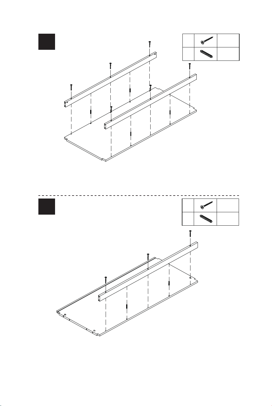
EN: Attach connect rail (1) to bottom panel (2) by using screw (C) and
wooden dowel (M). Do not overtighten.
FR: Fixez le rail de connexion (1) pour panneau inférieur (2) à l'aide de
la vis (C) et de la cheville en bois (M). Ne pas trop serrer
EN: Attach connect rail (3) to shelf panel (4) by using screw (C) and
wooden dowel (M). Do not overtighten.
FR: Fixez le rail de connexion (3) pour panneau de l'étagère (4) à l'aide
de la vis (C) et de la cheville en bois (M). Ne pas trop serrer.
3
8
A
A
M
F
B
4
2
G
H
M
8
B
F
H
G
3
1
1
R
R
A
B
M
F
G
H
x2
x2
x2
x2
x1
x6
R
x2
06 07
M
C
1
1
2
M
C
3
4
1
2
C
M
x6
x4
C
M
x3
x2
EN: Attach connect rail (1) to bottom panel (2) by using screw (C) and
wooden dowel (M). Do not overtighten.
FR: Fixez le rail de connexion (1) pour panneau inférieur (2) à l'aide de
la vis (C) et de la cheville en bois (M). Ne pas trop serrer
EN: Attach connect rail (3) to shelf panel (4) by using screw (C) and
wooden dowel (M). Do not overtighten.
FR: Fixez le rail de connexion (3) pour panneau de l'étagère (4) à l'aide
de la vis (C) et de la cheville en bois (M). Ne pas trop serrer.
3
8
A
A
M
F
B
4
2
G
H
M
8
B
F
H
G
3
1
1
R
R
A
B
M
F
G
H
x2
x2
x2
x2
x1
x6
R
x2

08 09
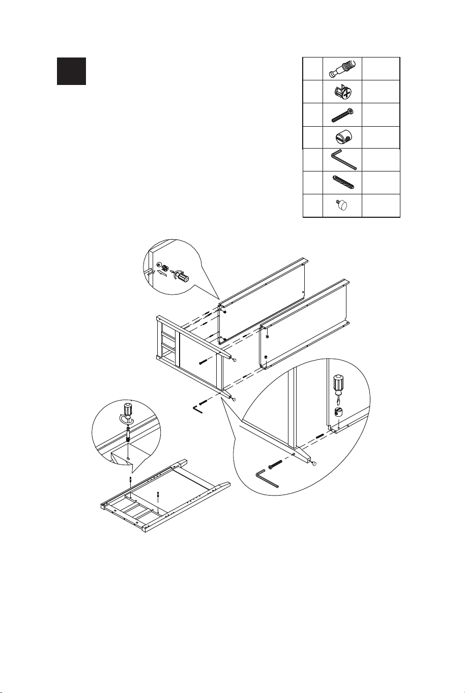
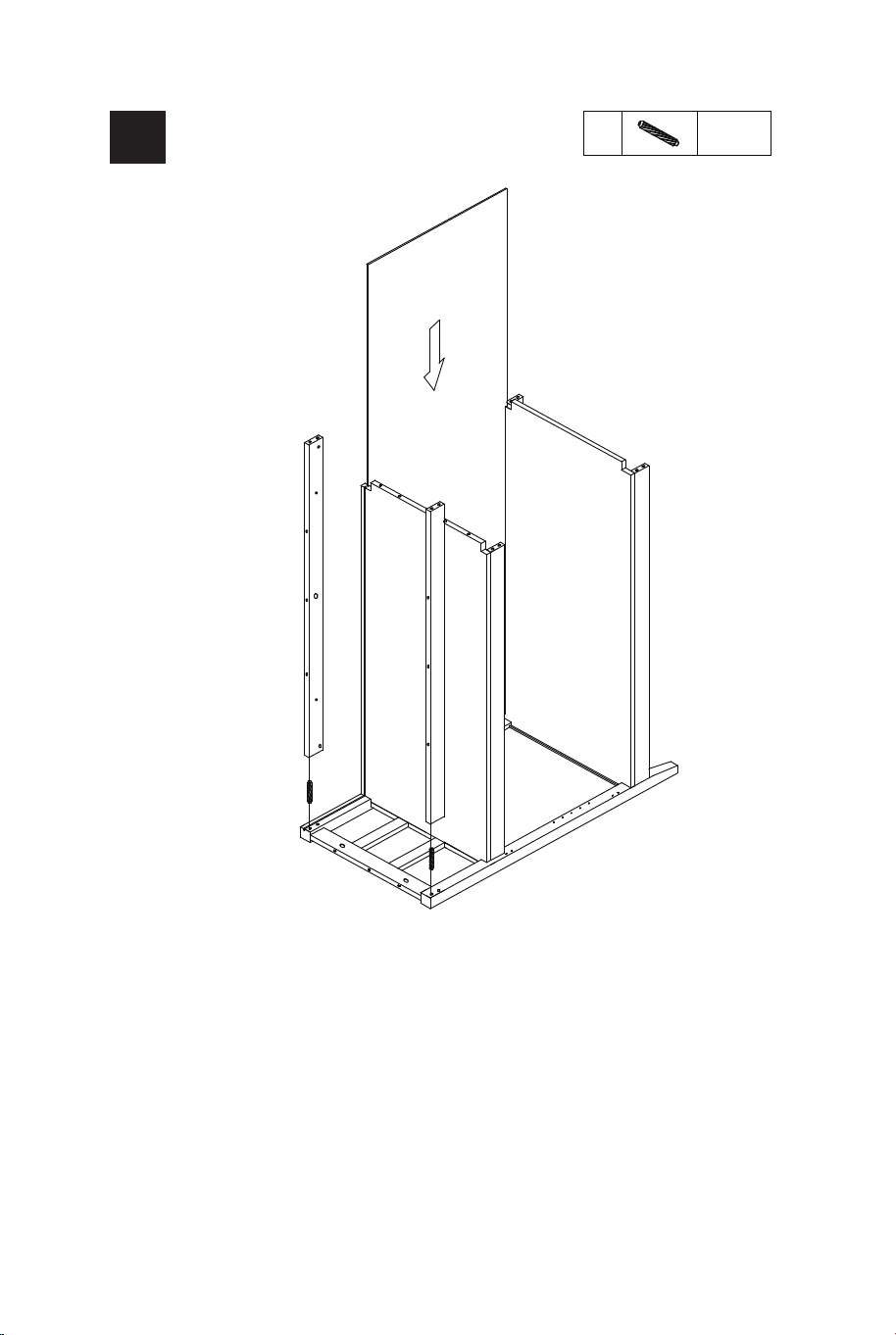
EN: a) Rotate the part from step 3 carefully. Insert Lower Back
Panel (12) via the the groove on (2 & 4).
b) Insert Wood Dowel (M) to Connect Rail (5 & 14), then Attach (5
& 14) to (8). Please hold (5 & 14) another person.
FR: a) Faites pivoter la pièce de l'étape 3 avec précaution. Insérez
le panneau arrière inférieur (12) via la rainure sur (2 et 4).
b) Insérez la cheville en bois (M) pour connecter le rail (5 et 14),
puis fixez (5 et 14) à (8). Veuillez tenir (5 & 14) une autre personne.
EN:
a) Screw in Cam-bolt (A) to Left Side Panel (8).
b) Insert Wood Dowel (M) to the designated holes on (1,2,3 & 4)
as shown.
c) Attach (8) to (3 and 4) via Cam-bolts and Wood Dowels.
d) Insert Cam-lock (B) to the designated holes on (4) then rotate
clockwise to secure Cam-bolt in place.
e) Attach (1 & 2) to (8) via Wood Dowels.
f) Insert barrel nut (G) to the desiganted holes on connect rail (1)
in right direction.
g) Screw the Allen Head Bolt (F) to tighten (8) to (1) by using
Allen Wrench (H).
h) Mounting adjust the leg studs(R), and the bottom rotating
screw can be adjusted to adapt to uneven ground.
FR: a) Visser le boulon à came (A) sur le panneau latéral gauche (8).
b) Insérez la cheville en bois (M) dans les trous désignés sur (1, 2, 3
et 4) tel qu'illustré.
c) Fixez (8) à (3 et 4) via des boulons à came et des chevilles en
bois.
d) Insérez le verrou à came (B) dans les trous désignés sur (4), puis
tournez dans le sens des aiguilles d'une montre pour fixer le boulon à
came en place.
e) Fixez (1 & 2) à (8) via des chevilles en bois.
f) Insérez l'écrou de baril (G) dans les trous désignés sur le rail de
connexion (1) dans la bonne direction.
g) Vissez le boulon à tête Allen (F) pour serrer (8) à (1) à l'aide de la
clé Allen (H).
h) Le montage ajuste les goujons des pieds (R) et la vis rotative
inférieure peut être ajustée pour s'adapter à un sol inégal.
4
12
14
5
M
2
4
8
M
x2
08 09
EN: a) Rotate the part from step 3 carefully. Insert Lower Back
Panel (12) via the the groove on (2 & 4).
b) Insert Wood Dowel (M) to Connect Rail (5 & 14), then Attach (5
& 14) to (8). Please hold (5 & 14) another person.
FR: a) Faites pivoter la pièce de l'étape 3 avec précaution. Insérez
le panneau arrière inférieur (12) via la rainure sur (2 et 4).
b) Insérez la cheville en bois (M) pour connecter le rail (5 et 14),
puis fixez (5 et 14) à (8). Veuillez tenir (5 & 14) une autre personne.
EN:
a) Screw in Cam-bolt (A) to Left Side Panel (8).
b) Insert Wood Dowel (M) to the designated holes on (1,2,3 & 4)
as shown.
c) Attach (8) to (3 and 4) via Cam-bolts and Wood Dowels.
d) Insert Cam-lock (B) to the designated holes on (4) then rotate
clockwise to secure Cam-bolt in place.
e) Attach (1 & 2) to (8) via Wood Dowels.
f) Insert barrel nut (G) to the desiganted holes on connect rail (1)
in right direction.
g) Screw the Allen Head Bolt (F) to tighten (8) to (1) by using
Allen Wrench (H).
h) Mounting adjust the leg studs(R), and the bottom rotating
screw can be adjusted to adapt to uneven ground.
FR: a) Visser le boulon à came (A) sur le panneau latéral gauche (8).
b) Insérez la cheville en bois (M) dans les trous désignés sur (1, 2, 3
et 4) tel qu'illustré.
c) Fixez (8) à (3 et 4) via des boulons à came et des chevilles en
bois.
d) Insérez le verrou à came (B) dans les trous désignés sur (4), puis
tournez dans le sens des aiguilles d'une montre pour fixer le boulon à
came en place.
e) Fixez (1 & 2) à (8) via des chevilles en bois.
f) Insérez l'écrou de baril (G) dans les trous désignés sur le rail de
connexion (1) dans la bonne direction.
g) Vissez le boulon à tête Allen (F) pour serrer (8) à (1) à l'aide de la
clé Allen (H).
h) Le montage ajuste les goujons des pieds (R) et la vis rotative
inférieure peut être ajustée pour s'adapter à un sol inégal.
4
12
14
5
M
2
4
8
M
x2
10 11
A
A
9
G
9
F
M
B
F
M
G
H
H
B
14
5
2
4
1
3
R
A
B
M
F
G
x2
x2
x4
x4
x8
R
x2
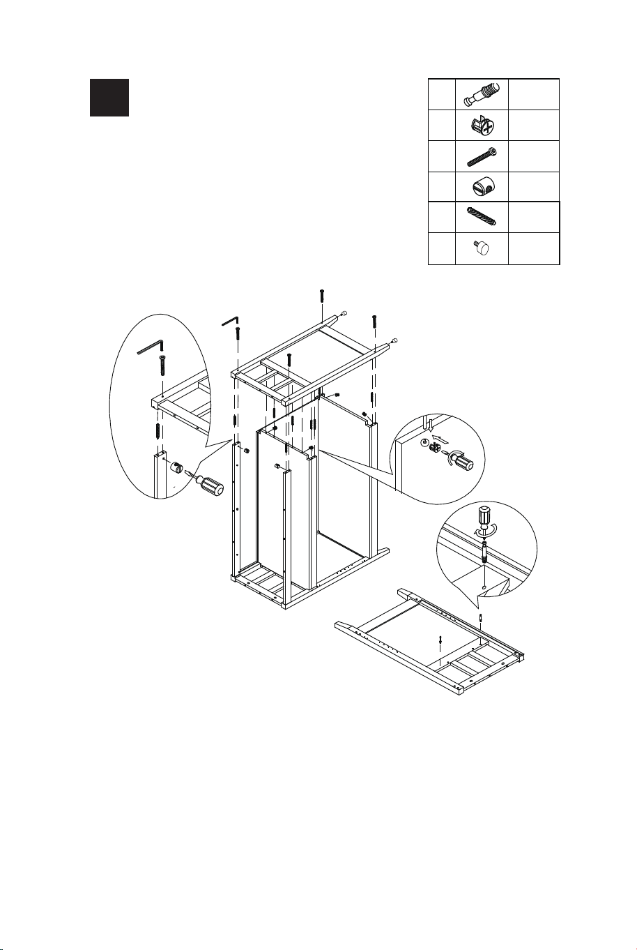
EN:
a) Screw in Cam-boit (A) to Right Side Panel (9).
b) Insert Wood Dowel (M) to (1, 2, 3, 4, 5 & 14).
c) Attach (9) to (1, 2, 3, 4, 5 & 14) via Cam-bolts and Wood
Dowels. Please assue the Back Panel just in the place of the
groove on (9).
d) Insert Cam-lock (B) to the desiganted holes on (4) then rotate
clockwise to secure Cam-bolt in place.
e) Insert Barrel Nut (G) to the designated holes on Connect Rails
(1, 5 & 14) in right direction.
f) Screw the Allen Head Boit (F) to tighten (9) to (1, 5 & 14) by
using Allen Wrench (H).
g) Mounting adjust the leg studs(R), and the bottom rotating
screw can be adjusted to adapt to uneven ground.
FR: a) Visser le boulon à came (A) sur le panneau latéral droit (9).
b) Insérez la cheville en bois (M) dans (1, 2, 3, 4, 5 et 14).
c) Fixez (9) à (1, 2, 3, 4, 5 et 14) via des boulons à came et des
chevilles en bois. Assurez-vous que le panneau arrière est juste à la
place de la rainure sur (9).
d) Insérez le verrou à came (B) dans les trous désignés sur (4), puis
tournez dans le sens des aiguilles d'une montre pour fixer le boulon
à came en place.
e) Insérez l'écrou de baril (G) dans les trous désignés sur les rails
de connexion (1, 5 et 14) dans la bonne direction.
f) Vissez le boitier à tête Allen (F) pour serrer (9) à (1, 5 et 14) à
l'aide de la clé Allen (H).
g) Le montage ajuste les goujons de jambe (R) et la vis rotative
inférieure peut être ajustée pour s'adapter à un sol inégal.
5

10 11
A
A
9
G
9
F
M
B
F
M
G
H
H
B
14
5
2
4
1
3
R
A
B
M
F
G
x2
x2
x4
x4
x8
R
x2
EN:
a) Screw in Cam-boit (A) to Right Side Panel (9).
b) Insert Wood Dowel (M) to (1, 2, 3, 4, 5 & 14).
c) Attach (9) to (1, 2, 3, 4, 5 & 14) via Cam-bolts and Wood
Dowels. Please assue the Back Panel just in the place of the
groove on (9).
d) Insert Cam-lock (B) to the desiganted holes on (4) then rotate
clockwise to secure Cam-bolt in place.
e) Insert Barrel Nut (G) to the designated holes on Connect Rails
(1, 5 & 14) in right direction.
f) Screw the Allen Head Boit (F) to tighten (9) to (1, 5 & 14) by
using Allen Wrench (H).
g) Mounting adjust the leg studs(R), and the bottom rotating
screw can be adjusted to adapt to uneven ground.
FR: a) Visser le boulon à came (A) sur le panneau latéral droit (9).
b) Insérez la cheville en bois (M) dans (1, 2, 3, 4, 5 et 14).
c) Fixez (9) à (1, 2, 3, 4, 5 et 14) via des boulons à came et des
chevilles en bois. Assurez-vous que le panneau arrière est juste à la
place de la rainure sur (9).
d) Insérez le verrou à came (B) dans les trous désignés sur (4), puis
tournez dans le sens des aiguilles d'une montre pour fixer le boulon
à came en place.
e) Insérez l'écrou de baril (G) dans les trous désignés sur les rails
de connexion (1, 5 et 14) dans la bonne direction.
f) Vissez le boitier à tête Allen (F) pour serrer (9) à (1, 5 et 14) à
l'aide de la clé Allen (H).
g) Le montage ajuste les goujons de jambe (R) et la vis rotative
inférieure peut être ajustée pour s'adapter à un sol inégal.
5
12 13
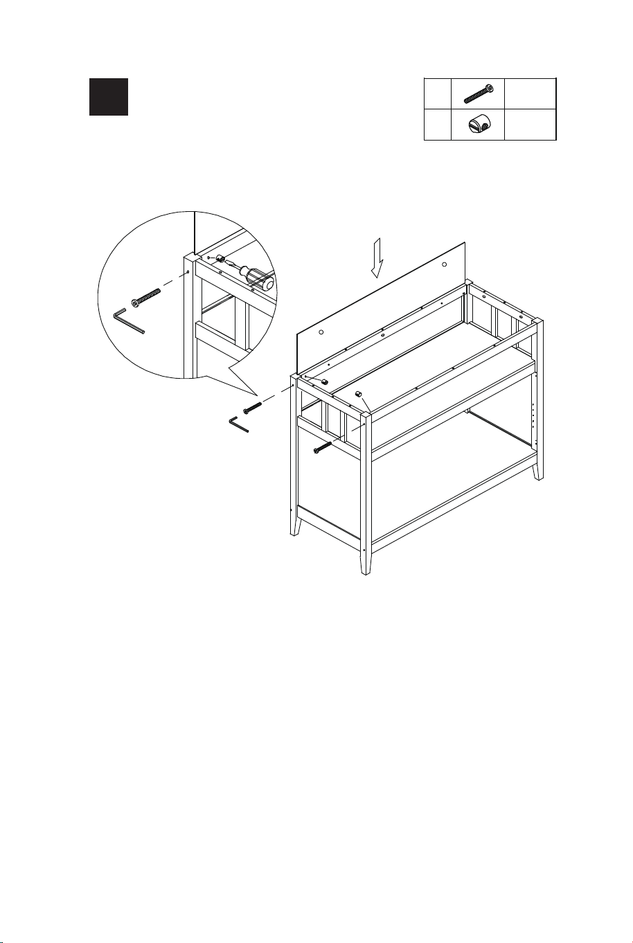
EN: a) Rotate the part from STEP 5 carefully. Insert Upper Back
Panel (13) via the groove on Side Panels.
b) Insert Barrel Nut (G) to Connect Rail (5 & 14) in right direction.
c) Screw the Allen Head Bolt (F) to tighten (9) to (5 & 14) by
using Allen Wrench (H).
FR: a) Faites pivoter la pièce de l'ÉTAPE 5 avec précaution.
Insérez le panneau arrière supérieur (13) dans la rainure des
panneaux latéraux.
b) Insérez l'écrou de baril (G) dans les rails de connexion (5 et
14) dans le bon sens.
c) Vissez le boulon à tête Allen (F) pour serrer (9) à (5 et 14) à
l'aide de la clé Allen (H).
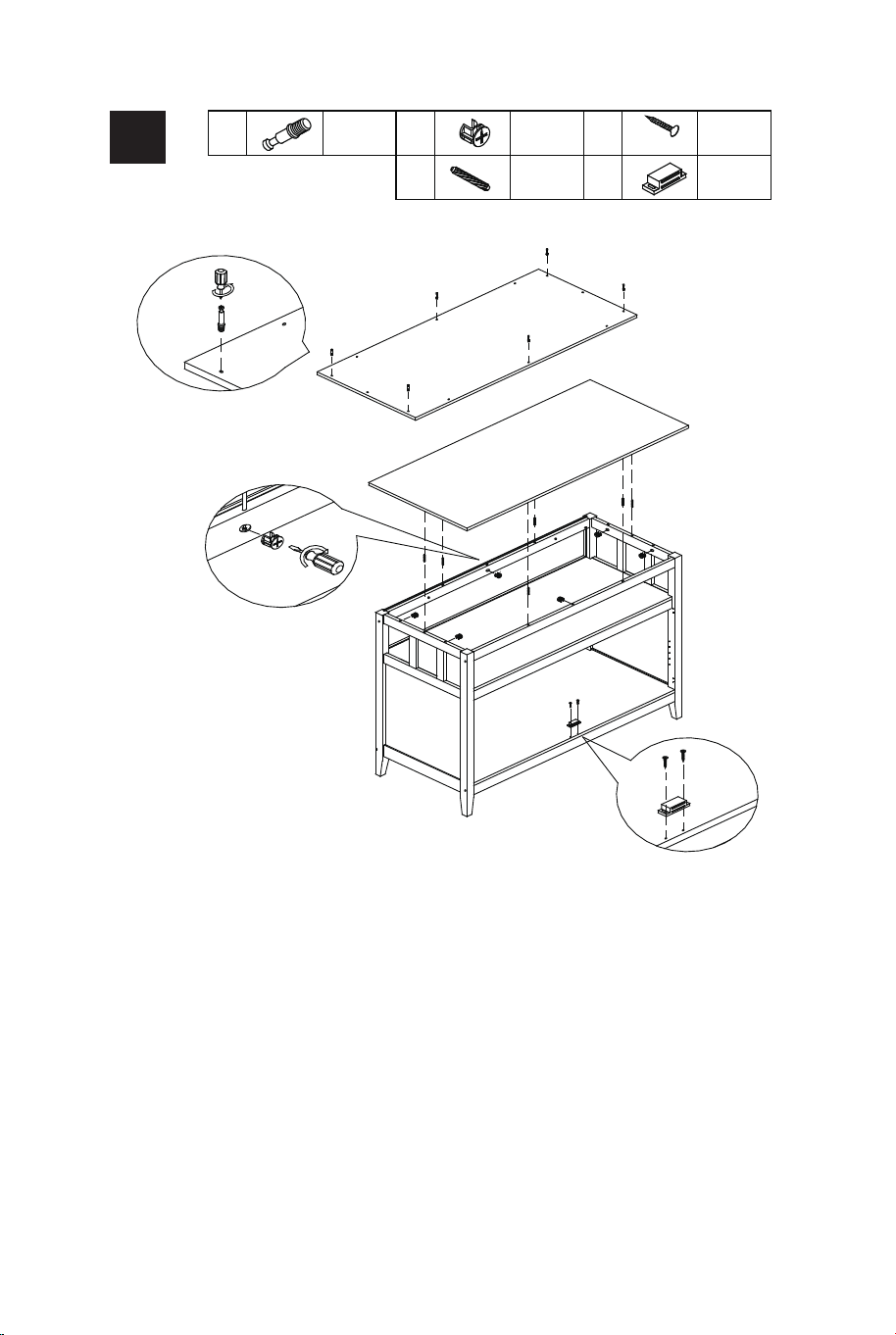
EN: a) Screw in Cam-bolt (A) to Top Panel (6).
b) Insert Wood Dowels (M) to (5, 8, 9 and 14).
c) Insert Cam-lock (B) to the designated holes on (5, 8, 9 & 14) then
rotate clockwise to secure Cam-bolt in place.
d) Attach Magnetic Catch (N) to Bottom Panel (2) by using screw (D).
FR: a) Visser le boulon à came (A) sur le panneau supérieur (6).
b) Insérez les chevilles en bois (M) dans (5, 8, 9 et 14).
c) Insérez le verrou à came (B) dans les trous désignés sur (5, 8, 9 et
14) puis tournez dans le sens des aiguilles d'une montre pour fixer le
boulon à came en place.
d) Fixez le loquet magnétique (N) au panneau inférieur (2) à l'aide de
la vis (D).
13
F
G
F
G
H
H
14
5
A
6
A
B
6
A
M
B
D
N
D
N
5
14
8
9
2
2
NM
DB A
3*14mm
x6 x6 x2
x6 x1
F
G
x2
x2
6
7
12 13
EN: a) Rotate the part from STEP 5 carefully. Insert Upper Back
Panel (13) via the groove on Side Panels.
b) Insert Barrel Nut (G) to Connect Rail (5 & 14) in right direction.
c) Screw the Allen Head Bolt (F) to tighten (9) to (5 & 14) by
using Allen Wrench (H).
FR: a) Faites pivoter la pièce de l'ÉTAPE 5 avec précaution.
Insérez le panneau arrière supérieur (13) dans la rainure des
panneaux latéraux.
b) Insérez l'écrou de baril (G) dans les rails de connexion (5 et
14) dans le bon sens.
c) Vissez le boulon à tête Allen (F) pour serrer (9) à (5 et 14) à
l'aide de la clé Allen (H).
EN: a) Screw in Cam-bolt (A) to Top Panel (6).
b) Insert Wood Dowels (M) to (5, 8, 9 and 14).
c) Insert Cam-lock (B) to the designated holes on (5, 8, 9 & 14) then
rotate clockwise to secure Cam-bolt in place.
d) Attach Magnetic Catch (N) to Bottom Panel (2) by using screw (D).
FR: a) Visser le boulon à came (A) sur le panneau supérieur (6).
b) Insérez les chevilles en bois (M) dans (5, 8, 9 et 14).
c) Insérez le verrou à came (B) dans les trous désignés sur (5, 8, 9 et
14) puis tournez dans le sens des aiguilles d'une montre pour fixer le
boulon à came en place.
d) Fixez le loquet magnétique (N) au panneau inférieur (2) à l'aide de
la vis (D).
13
F
G
F
G
H
H
14
5
A
6
A
B
6
A
M
B
D
N
D
N
5
14
8
9
2
2
NM
DB A
3*14mm
x6 x6 x2
x6 x1
F
G
x2
x2
6
7
14 15
E
I
J
K
O
3*12mm
x10
x4
x4
x2
x2
E
L
3*12mm
x8
x4
J
K
E
I
10
E
O
J
K
E
I
11
E
O
E
I
E
O
7
10
11
E
L
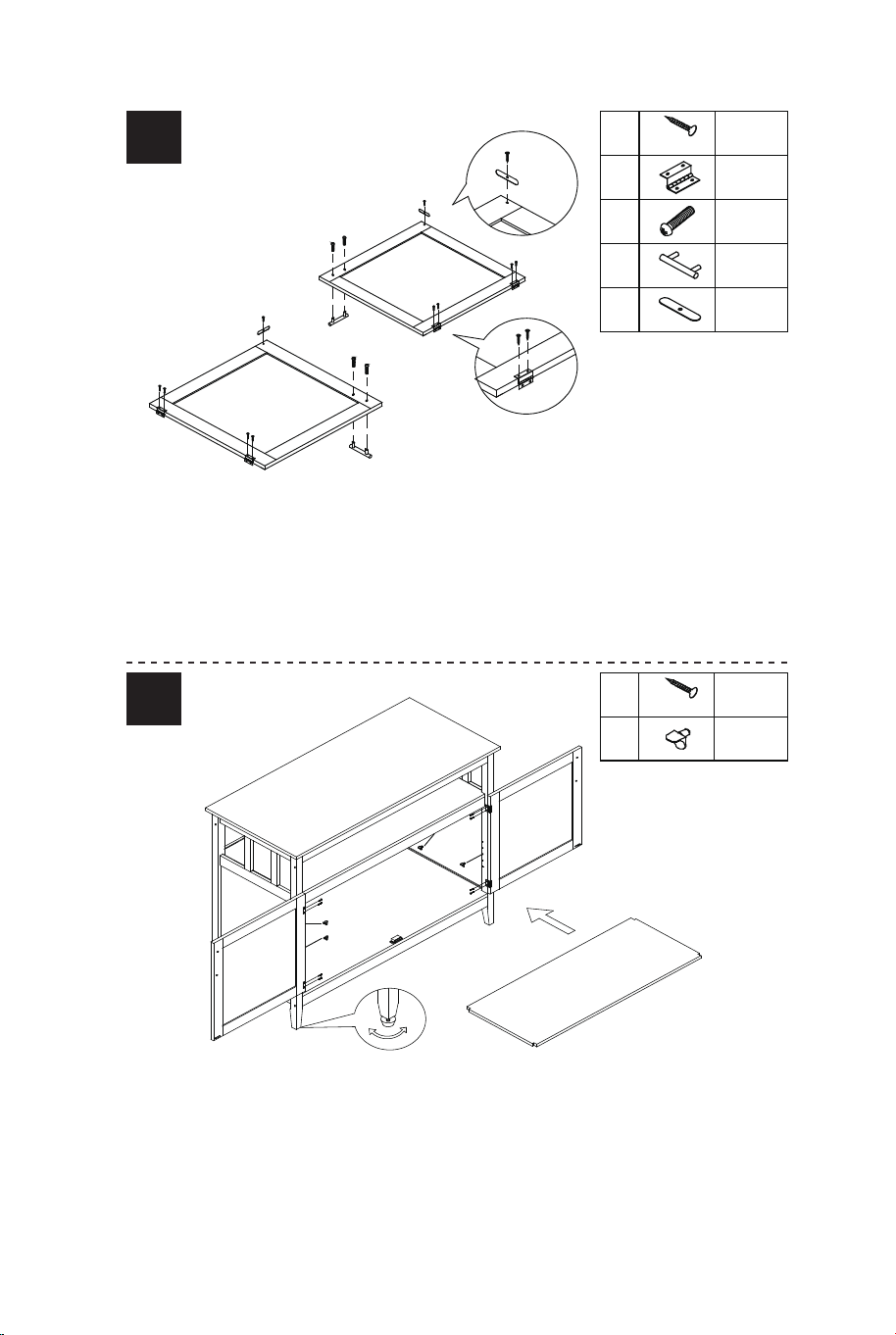
EN: a) Attach Hinge (I) and Magnetic Bar (O) to Door (10 & 11) by using
Screw (E).
b) Attach Handel (K) to Door (10 & 11) by using Handle Bolt (J).
FR: a) Fixez la charnière (I) et la barre magnétique (O) à la porte (10 et
11) à l'aide de la vis (E).
b) Fixez la poignée (K) à la porte (10 et 11) à l'aide du boulon de
poignée (J).
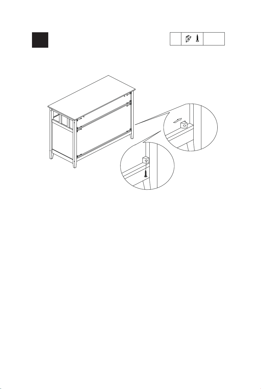
EN: Insert Fixed (P) to the gap between Back panel and Side
Panel, then fix it by using the Screw (P) as shown. The assembly
of the Cabinet unit is complete.
FR: Insérez le boulon fixe (P) dans l'espace entre le panneau
arrière et le panneau latéral, puis fixez-le à l'aide de la vis (P)
comme indiqué. L'assemblage du meuble est terminé.
EN: a) Attach Doors (10 & 11) to Side Panels by using Screw (E).
b) Insert Shelf Pin (L) to the designated holes on Side Panels, then
place Adjustable Sheif (7) on it.
FR: a) Fixez les portes (10 et 11) aux panneaux latéraux à l'aide de la
vis (E).
b) Insérez la goupille d’étagère (L) dans les trous désignés sur les
panneaux latéraux, puis placez la étagère réglable (7) dessus.
8 10
9
P
P
P
P
x8
14 15
E
I
J
K
O
3*12mm
x10
x4
x4
x2
x2
E
L
3*12mm
x8
x4
J
K
E
I
10
E
O
J
K
E
I
11
E
O
E
I
E
O
7
10
11
E
L
EN: a) Attach Hinge (I) and Magnetic Bar (O) to Door (10 & 11) by using
Screw (E).
b) Attach Handel (K) to Door (10 & 11) by using Handle Bolt (J).
FR: a) Fixez la charnière (I) et la barre magnétique (O) à la porte (10 et
11) à l'aide de la vis (E).
b) Fixez la poignée (K) à la porte (10 et 11) à l'aide du boulon de
poignée (J).
EN: Insert Fixed (P) to the gap between Back panel and Side
Panel, then fix it by using the Screw (P) as shown. The assembly
of the Cabinet unit is complete.
FR: Insérez le boulon fixe (P) dans l'espace entre le panneau
arrière et le panneau latéral, puis fixez-le à l'aide de la vis (P)
comme indiqué. L'assemblage du meuble est terminé.
EN: a) Attach Doors (10 & 11) to Side Panels by using Screw (E).
b) Insert Shelf Pin (L) to the designated holes on Side Panels, then
place Adjustable Sheif (7) on it.
FR: a) Fixez les portes (10 et 11) aux panneaux latéraux à l'aide de la
vis (E).
b) Insérez la goupille d’étagère (L) dans les trous désignés sur les
panneaux latéraux, puis placez la étagère réglable (7) dessus.
8 10
9
P
P
P
P
x8
16 17
Instructions De Retour / Réclamation De Dommages
Dans le cas où un retour est requis, l'article doit être retourné dans sa boîte
d'origine. Sans cela, votre retour ne sera pas accepté.
NE PAS jeter la boîte/l'emballage d'origine.
Prenez une photo des marquages de la boîte.
Prenez une photo des dommages (le cas échéant).
Envoyez-nous un e-mail avec les images demandées.
Une photo des marquages (texte) sur le côté de la boîte est requise au cas où
une pièce serait nécessaire pour le remplacement. Cela aide notre personnel à
identifier votre numéro de produit pour s'assurer que vous recevez les bonnes
pièces.
Une photo des dommages est toujours requise pour déposer une réclamation et
obtenir rapidement votre remplacement ou votre remboursement. Assurez-vous
d'avoir la boîte même si elle est endommagée.
Envoyez-nous un e-mail directement depuis le marché où votre article a été
acheté avec les images ci-jointes et une description de votre réclamation.
FR
In case a return is required, the item must be returned in original box. Without this
your return will not be accepted.
DO NOT discard the box / original packaging.
Take a photo of the box markings.
Take a photo of the damaged part (if applicable).
Send us an email with the images requested.
A photo of the markings (text) on the side of the box is required in case a part is
needed for replacement. This helps our staff identify your product number to
ensure you receive the correct parts.
A photo of the damage is always required to file a claim and get your replacement
or refund processed quickly. Please make sure you have the box even if it is
damaged.
Email us directly from marketplace where your item was purchased with the
attached images and a description of your claim.
EN
Return / Damage Claim Instructions
Instructions De Retour / Réclamation De Dommages
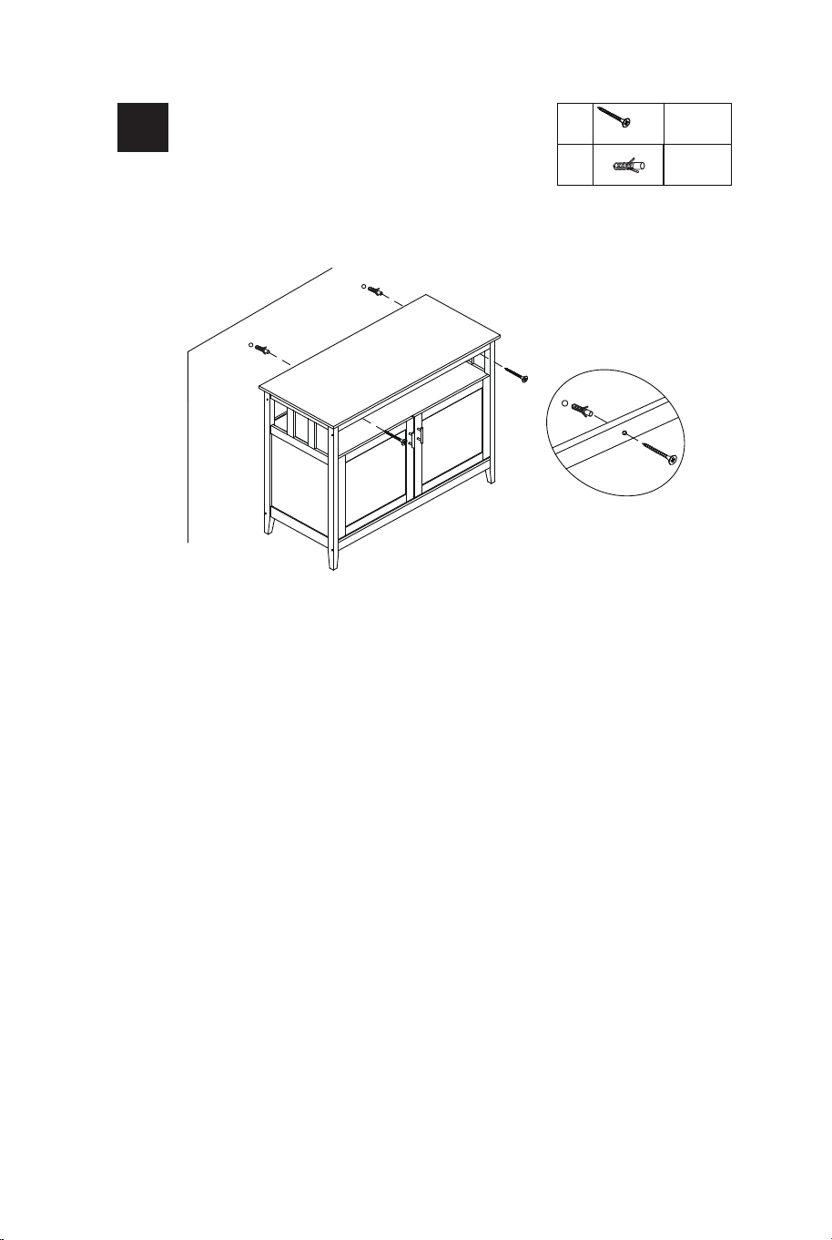
EN: a) Drill two holes in the dry wall as per the length and diame-
ter of Plastic Anchor (Q) and the distance between the holes and
the height need to the same as the screw holes on Connect Rail
(14).
b) Press Plastic wall anchor (Q) into the 2 drilled holes. Ensure
that the anchor fits securely in the wall.
c) Drive Screw (S) through the screw hole on (14) into the screw
hole on (Q) to secure the Cabinet to the wall.
FR: a) Percez deux trous dans la cloison sèche selon la longueur
et le diamètre de l'ancrage en plastique (Q) et la distance entre
les trous et la hauteur doivent être identiques à celles des trous
de vis sur le rail de connexion (14).
b) Enfoncez l'ancrage mural en plastique (Q) dans les 2 trous
percés. Assurezvous que l'ancre s'insère solidement dans le
mur.
c) Vissez la vis (S) à travers le trou de vis de (14) dans le trou de
vis de (Q) pour fixer l'armoire au mur.
WALL
WAND
MUR
PARED
PARETE
SCIANA
\
S
Q
Q
S
14
S
Q
x2
x2
11
4x70mm
16 17
Instructions De Retour / Réclamation De Dommages
Dans le cas où un retour est requis, l'article doit être retourné dans sa boîte
d'origine. Sans cela, votre retour ne sera pas accepté.
NE PAS jeter la boîte/l'emballage d'origine.
Prenez une photo des marquages de la boîte.
Prenez une photo des dommages (le cas échéant).
Envoyez-nous un e-mail avec les images demandées.
Une photo des marquages (texte) sur le côté de la boîte est requise au cas où
une pièce serait nécessaire pour le remplacement. Cela aide notre personnel à
identifier votre numéro de produit pour s'assurer que vous recevez les bonnes
pièces.
Une photo des dommages est toujours requise pour déposer une réclamation et
obtenir rapidement votre remplacement ou votre remboursement. Assurez-vous
d'avoir la boîte même si elle est endommagée.
Envoyez-nous un e-mail directement depuis le marché où votre article a été
acheté avec les images ci-jointes et une description de votre réclamation.
FR
In case a return is required, the item must be returned in original box. Without this
your return will not be accepted.
DO NOT discard the box / original packaging.
Take a photo of the box markings.
Take a photo of the damaged part (if applicable).
Send us an email with the images requested.
A photo of the markings (text) on the side of the box is required in case a part is
needed for replacement. This helps our staff identify your product number to
ensure you receive the correct parts.
A photo of the damage is always required to file a claim and get your replacement
or refund processed quickly. Please make sure you have the box even if it is
damaged.
Email us directly from marketplace where your item was purchased with the
attached images and a description of your claim.
EN
Return / Damage Claim Instructions
Instructions De Retour / Réclamation De Dommages
EN: a) Drill two holes in the dry wall as per the length and diame-
ter of Plastic Anchor (Q) and the distance between the holes and
the height need to the same as the screw holes on Connect Rail
(14).
b) Press Plastic wall anchor (Q) into the 2 drilled holes. Ensure
that the anchor fits securely in the wall.
c) Drive Screw (S) through the screw hole on (14) into the screw
hole on (Q) to secure the Cabinet to the wall.
FR: a) Percez deux trous dans la cloison sèche selon la longueur
et le diamètre de l'ancrage en plastique (Q) et la distance entre
les trous et la hauteur doivent être identiques à celles des trous
de vis sur le rail de connexion (14).
b) Enfoncez l'ancrage mural en plastique (Q) dans les 2 trous
percés. Assurezvous que l'ancre s'insère solidement dans le
mur.
c) Vissez la vis (S) à travers le trou de vis de (14) dans le trou de
vis de (Q) pour fixer l'armoire au mur.
WALL
WAND
MUR
PARED
PARETE
SCIANA
\
S
Q
Q
S
14
S
Q
x2
x2
11
4x70mm

HW53869
Kitchen Sideboard Cabinet
Meuble de Cuisine
THIS INSTRUCTION BOOKLET CONTAINS IMPORTANT SAFETY INFORMATION. PLEASE READ AND KEEP FOR FUTURE REFERENCE.
If you're having difficulty, our friendly
customer team is always here to help.
USA office: Fontana AUS office: Truganina
GBR office: Ipswich FRA office: Saint Vigor d'Ymonville
AUS:cs.au@costway.com
GBR:cs.uk@costway.com
FRA:cs.fr@costway.com