Loading ...
Loading ...
Loading ...
I
nstallation RequirementsInstallation Requirements
WARNING
• Observe all governing codes and ordinances during
planning and installation. Contact your local building
department for further information.
• To prevent an electric shock hazard, the power supply
must meet the specifications stated below.
T
he electrical and gas supply data on this page is for
reference only. If the requirements below do not agree
with the product data label, use the data on the product
data label.
E
lectrical Requirements
•
The electrical installation, including minimum
supply wire size and grounding, must be done in
accordance with National Electric Code ANSI/NFPA
70 and local codes and ordinances. A copy of this
standard may be obtained from:
National Fire Protection Association
1 %DWWHU\PDUFK Park
Quincy, MA 02269-9101
• The correct voltage, frequency and amperage must be
supplied to the electrical outlet according to the
product data label located on the bottom of the chassis.
• The electrical outlet must be installed by a licensed
electrician.
E
LECTRIC CIRCUIT REQUIREMENTS
Circuit Required
Total Connected Load
120 V 60Hz ,
Minimum 15 Amp.
0.25 Amp
@ 120 V, 60 Hz
P
roduct Dimensions
Gas Supply Requirements
• C
heck your local building codes for the proper method
of installation. In the absence of local codes, this
appliance should be installed in accordance with the
National Fuel Gas Code ANSI Z223.1/NFPA 54. The
gas service must be installed by a qualified professional
• Be certain that the cooktop being installed is correct for
the gas service being provided (natural gas or LP gas).
Also, if operating the cooktop at an altitude above 4000
ft. (1219 m) make sure it is equipped for high altitude
operation. See the inside cover for more information.
• An external manual shut-off valve must be installed
between the gas inlet and the cooktop for the purpose
of turning on or shutting off gas to the appliance.
• AQ\ standard regulator PD\QHHGWR be installed inWR the gas
liQHthat runs from the gas shut off valve to the cooktop
gas inlet. Use only a regulator inlet that accommodates
a 3/4” gas supply line and is also compatible with a
1/2” house gas supply.$Q\EUDQGQDPHUHJXODWRUZLOOVXIILFH
The inlet to the cooktop itself LVequipped with a ” male
137 fitting DTXLFNFRQQHFWJDVILWWLQJPD\EHVFUHZHGRQWKH
137ILWWLQJVLPSO\XQVFUHZZLWKDZUHQFKDQGDWWDFKD
IODUHILWWLQJ(QVXUHJDVVHDODQWLVXVHGRQWKHWKUHDGLQJ
G
AS SUPPLY PRESSURE REQUIREMENTS*
Gas Type
Manifold
Pressure
Minimum Gas
Supply Pressure
Natural Gas
Propane (LP)
5” Water Column
10” Water
Column
6” Water Column
11” Water
Column
* Maximum gas supply pressure for all models is 1/2 p.s.i.
137VWDQGVIRU1DWLRQDO3LSH7KUHDG
” gas inlet, connects to JDVKRVH frombottom or rear of unit,
end is recessed 2” (51 mm) from KREVbottom. 8QVFUHZ,WDOLDQ
VW\OHTXLFNFRQQHFWILWWLQJLIDSSOLFDEOHDQGUHSODFHZLWKIODUH
ILWWLQJ
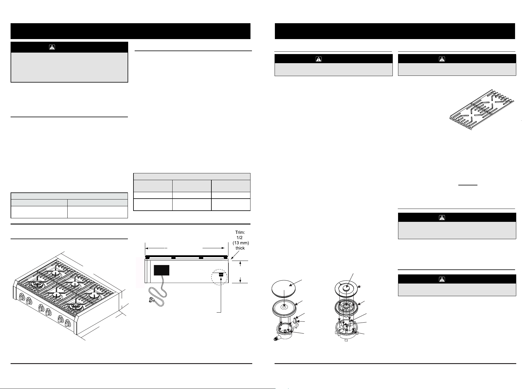
P
roduct tolerances: ±1/16” (±1.6 mm) unless otherwise
noted.
REAR VIEW
5
8 1
/3 Inch
35 3/8 Inches
8 1/3”
2
3 5/8 “
35 3/8”
Electrical
Te
rmin al
Box/Cover
G
rate does not protrude in actual unit
Approximate position of
gas & electrical.
CAUTION
CAUTION
CAUTION
Continued...
C
are and Cleaning
B
urner Components and IgniterGrates, Spill Trays and WOK Ring
U
se care while cleaning the igniter. The porcelain is
fragile and can crack or break.
IMPORTANT: The igniter may not spark or work
properly if the burner parts or the igniter themselves
are not clean and dry.
After disassembling the burners, check for any dirt
or grime deposited on the individual parts, including
the igniter.
1. Use a firm toothbrush to clean completely around
the igniter, including all of the metal top and porcelain
base. Use care while cleaning because the porcelain is
fragile and can crack or break. Do not use water to
clean the igniter. If necessary, use a small amount of
rubbing alcohol to help dissolve grime.
2. Examine the burner rings. Remove anything
stuck in the holes with a straightened paper
clip, wire or needle. Be careful not to scratch or
damage the ring and head. Do not distort the
shape of the burner ring holes.
3. Clean all of the burner parts, including the burner
bases, with window cleaner or rubbing alcohol. Use a
cleaning brush with plastic bristles or a firm tooth
brush. When done, rinse the parts well with clean water.
Dry all the parts thoroughly before re-assembling them.
4. Reassemble the cooktop according to the burner and
grate assembly instructions. Test the burners after
reassembling them. If the flame is uneven, be sure that
all the burner parts are properly positioned, then check
for any remaining dirt or grime on the burner parts or
igniter. If erratic sparking (clicking) is still present,
make sure the igniter is completely dry. If the unit still
exhibits problems after drying, call your local Vervice Dgent.
CAUTION
Do not clean the cooktop grates, burner parts in a
dishwasher. They will be damaged.
The gratesDQG the spill tray are
coated with a porcelain finish.
• For everyday cleaning,use a soft cloth
or nonabrasivepad with warm
soapy water to clean all
of the porcelain parts.
• If necessary, tough
stains may be removed
by applying full-strength
sprays such as Simple
Green™, Ajax™ All-Purpose Cleaner or Formula
409™. To minimize wear, use the mildest cleaner
needed to get the surface clean.
• For extremely stubborn stains, you may use a
mildly abrasive cleaner or applicator, such as
Soft Scrub™, Bon Ami™, S.O.S. pads or other
soap-filled steel wool pads. Use these cleaners
with extreme care and only on occasion. Extensive
use of these types of abrasives will eventually
damage the porcelain enamel.XVH626SDGV
RURWKHUVWHHOZRROSDGVRQVWDLQOHVVVWHHO
S
tainless Steel Surfaces
Brass, Chrome and Copper Surfaces
Always wipe stainless steel (silver colored) surfaces.
To prevent scratching, do not use abrasive
c
leaners or scrubbers on stainless steel surfaces.
• 21/<XVHDVWRUHDGYHUWLVHG6WDLQOHVV6WHHO3ROLVKHURU
&OHDQHU.Rinse and dry with a soft, lint-free cloth.
T
o prevent scratching, do not use abrasive cleaners or
scrubbers on metal surfaces.
Using a soft cloth, clean metal surfaces with a mild
solution of DVWRUHDGYHUWLVHG6WDLQOHVV6WHHORU0HWDO
&OHDQHU3ROLVKHU. Rinse and drywith a soft, lint-free cloth.
14
A
/ B Burner AssemblyC / D Burner Assembly
B
urner cap
Outer burner cap
Inner burner cap
Burner ring
Burner ring
Ignition pin
Ignition pin
Thermocouple
Thermocouple
Hole of the
burner base
Hole of the
burner base
Loading ...
Loading ...
Loading ...