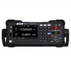

HBT4000 series
Internal resistance tester
User Manual
2023.12

Warranties and Declarations
Copyright
The copyright of this document belongs to Qingdao Hantek Electronic Co., LTD.
Statement
Qingdao Hantek Electronic Co., Ltd. reserves the right to amend this document without prior
notice. Qingdao Hantek Electronic Co., Ltd. promises that the information provided is correct
and reliable but does not guarantee that this document is free from errors. Before using this
product, please make sure that the specifications of relevant technical documents are the
latest effective version. If you use documents or products of Qingdao Hantek Electronic Co.,
LTD and need products, patents or works of third parties to cooperate with them, you shall
be responsible for obtaining the consent and authorization of the third parties. The above
consent and authorization shall not be the liability of Hantek.
Product certification
The Hantek certified HBT4000 series internal resistance tester meets Chinese national and
industry standards, and has passed CE certification and UKCA certification.
Contact Us
If you have any questions or uncertainties while using the products of Qingdao Hantek
Electronics Co., Ltd., you can obtain service and support through the following methods:
Email: service@hantek.com , support@hantek.com
Website: http://www.hantek.com

EN
Copyright © Qingdao Hantek Electronic Co., LTD HBT4000 series user manual
I
Contents
Contents ......................................................................................................................................... I
Figures ........................................................................................................................................ VII
Tables ............................................................................................................................................. X
1 Safety requirement ................................................................................................................ 1
1.1 Summary of general security issues ....................................................................................... 1
1.2 Security terms and signs ............................................................................................................. 2
1.3 Measurement category ............................................................................................................... 3
1.4 Ventilation Requirement ............................................................................................................. 4
1.5 Work Environment ........................................................................................................................ 5
1.6 Care and Cleaning ......................................................................................................................... 7
1.7 Environmental precautions ........................................................................................................ 8
2 Product features ..................................................................................................................... 9
3 Overview .................................................................................................................................. 10
4 Quick Start .............................................................................................................................. 14
4.1 General inspection ..................................................................................................................... 14
4.2 Appearance dimensions .......................................................................................................... 15
4.3 Preparation before use ............................................................................................................. 15

EN
HBT4000 series user manual Copyright © Qingdao Hantek Electronic Co., LTD
II
4.3.1 Connecting the power supply ........................................................................................................ 15
4.3.2 Adjusting the handle .......................................................................................................................... 16
4.3.3 Setting System Language ................................................................................................................. 17
4.4 Product Introduction ................................................................................................................. 17
4.4.1 Introduction to Front Panel ............................................................................................................. 17
4.4.2 Introduction to Rear Panel ............................................................................................................... 18
4.4.3 User Interface Introduction ............................................................................................................. 19
4.5 Set parameter values ................................................................................................................ 19
4.6 Using the built-in help system .............................................................................................. 20
5 Start using ............................................................................................................................... 21
5.1 Measurement Settings ............................................................................................................. 21
5.1.1 Setting Type .......................................................................................................................................... 21
5.1.2 Set voltage range ................................................................................................................................ 22
5.1.3 Setting the Resistance Range ......................................................................................................... 23
5.1.4 Setting the sampling rate ................................................................................................................. 23
5.2 Zeroing ........................................................................................................................................... 24
5.3 Test abnormal output ............................................................................................................... 24
6 Application measurement ................................................................................................. 26
6.1 Measurement Configuration .................................................................................................. 26

EN
Copyright © Qingdao Hantek Electronic Co., LTD HBT4000 series user manual
III
6.1.1 Setting the sampling rate ................................................................................................................. 26
6.1.2 Setting the average value ................................................................................................................ 27
6.1.3 Trigger function ................................................................................................................................... 27
6.1.4 Delay function ...................................................................................................................................... 28
6.1.5 Absolute value function .................................................................................................................... 28
6.2 Comparator function ................................................................................................................. 29
6.2.1 Comparator function settings......................................................................................................... 29
6.2.2 Setting the Limits and Percent ....................................................................................................... 31
6.2.3 Page display of comparator ............................................................................................................ 32
6.3 Statistical operation function ................................................................................................. 33
6.3.1 Switch of statistical function ........................................................................................................... 33
6.3.2 Statistical Results ................................................................................................................................. 33
6.3.3 Normal distribution diagram .......................................................................................................... 36
6.3.4 SAVE/LOAD ........................................................................................................................................... 36
6.3.5 Data Temp ............................................................................................................................................. 37
6.3.6 Data Clearing ........................................................................................................................................ 37
6.4 System Settings ........................................................................................................................... 37
6.5 Calibration ..................................................................................................................................... 38
6.6 IO ...................................................................................................................................................... 39

EN
HBT4000 series user manual Copyright © Qingdao Hantek Electronic Co., LTD
IV
6.6.1 LAN ........................................................................................................................................................... 40
6.6.2 Serial ........................................................................................................................................................ 40
6.6.3 GPIB .......................................................................................................................................................... 40
6.7 Other settings .............................................................................................................................. 41
6.7.1 System time ........................................................................................................................................... 41
6.7.2 Brightness .............................................................................................................................................. 41
6.7.3 Keytone ................................................................................................................................................... 42
6.7.4 Language ................................................................................................................................................ 42
6.7.5 Upgrade .................................................................................................................................................. 42
6.8 SAVE ................................................................................................................................................ 42
6.8.1 Save Path ................................................................................................................................................ 42
6.8.2 Inter/Exter Save .................................................................................................................................... 43
6.8.3 Boot Set .................................................................................................................................................. 43
6.9 Load ................................................................................................................................................. 43
6.9.1 Load Path ............................................................................................................................................... 43
6.9.2 Inter/Exter Save .................................................................................................................................... 44
6.9.3 Boot Set .................................................................................................................................................. 44
6.10 0 ADJ ............................................................................................................................................ 44
6.11 Local key ...................................................................................................................................... 45

EN
Copyright © Qingdao Hantek Electronic Co., LTD HBT4000 series user manual
V
6.12 TRIG key ...................................................................................................................................... 45
6.13 Plus/Minus keys ........................................................................................................................ 45
6.14 Range key ................................................................................................................................... 45
6.15 ESC key ........................................................................................................................................ 45
6.16 P key ............................................................................................................................................. 45
7 EXT I/O ..................................................................................................................................... 48
7.1 Input terminal function ............................................................................................................ 52
7.2 Output terminal function......................................................................................................... 53
8 Analog Output ...................................................................................................................... 55
8.1 Connect analog output ............................................................................................................ 55
9 Remote control ..................................................................................................................... 57
9.1 USB remote control ................................................................................................................... 57
9.2 LAN remote control ................................................................................................................... 57
9.3 Serial port control ...................................................................................................................... 59
9.4 GPIB Remote control ................................................................................................................. 61
10 Fault handling ..................................................................................................................... 63
11 Appendix ............................................................................................................................... 64
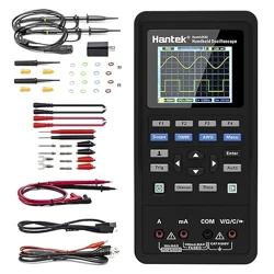
11.1 Appendix A: Models and Accessories ............................................................................... 64
11.2 Appendix B: AC Four Terminal Test Method .................................................................. 66

EN
HBT4000 series user manual Copyright © Qingdao Hantek Electronic Co., LTD
VI
11.3 Appendix C: Performing Zero Adjustment ..................................................................... 67
11.3.1 Zero adjustment wiring principle ................................................................................................ 67
11.3.2 Zero adjustment using clamp type test line ........................................................................... 68
11.3.3 Zero adjustment using needle shaped test lines .................................................................. 68
11.4 Appendix D: Warranty Summary ........................................................................................ 69

EN
Copyright © Qingdao Hantek Electronic Co., LTD HBT4000 series user manual
VII
Figures
Figure 4-1Front view ........................................................................................................ 15
Figure 4-2 vertical view ................................................................................................... 15
Figure 4-3 Handheld position ...................................................................................... 16
Figure 4-4 Front Panel ..................................................................................................... 17
Figure 4-5 Rear Panel ...................................................................................................... 18
Figure 4-6 User Interface ................................................................................................ 19
Figure 4-7 Keypad ............................................................................................................. 20
Figure 5-1 Measurement display interface .............................................................. 21
Figure 5-2 Measurement voltage interface ............................................................. 22
Figure 5-3 Measurement resistance interface ........................................................ 22
Figure 5-4 Measurement display interface .............................................................. 24
Figure 5-5 Zeroing ............................................................................................................ 24
Figure 5-6 Test exception ............................................................................................... 25
Figure 5-7 Measure overflow ........................................................................................ 25
Figure 6-1 Measurement display interface .............................................................. 26
Figure 6-2 Set sampling rate......................................................................................... 27
Figure 6-3 Set average value ........................................................................................ 27
Figure 6-4 Set trigger source ........................................................................................ 28
Figure 6-5 Setting Delay ................................................................................................. 28
Figure 6-6 Set absolute value function ..................................................................... 29

EN
HBT4000 series user manual Copyright © Qingdao Hantek Electronic Co., LTD
VIII
Figure 6-7 Set comparator function ........................................................................... 30
Figure 6-8 Set the upper and lower limits of resistance ..................................... 31
Figure 6-9 Keypad ............................................................................................................. 32
Figure 6-10 page display ................................................................................................ 32
Figure 6-11 Statistical operation function ................................................................ 33
Figure 6-13 statistical indicators .................................................................................. 34
Figure 6-14 Statistical List .............................................................................................. 35
Figure 6-15 Statistical List .............................................................................................. 35
Figure 6-16 Normal distribution diagram ................................................................ 36
Figure 6-17 Normal distribution diagram ................................................................ 36
Figure 6-19 System settings .......................................................................................... 38
Figure 6-20 Voltage Calibration ................................................................................... 39
Figure 6-21 LAN parameter settings .......................................................................... 40
Figure 6-22 Set system time ......................................................................................... 41
Figure 7-1 EXT I/O connector ....................................................................................... 48
Figure 8-1Connection diagram .................................................................................... 56
Figure 9-1 Set LAN parameters ................................................................................... 58
Figure 9-2 Set computer Ethernet properties ......................................................... 58
Figure 9-3 Manually adding devices .......................................................................... 59
Figure 9-4 Network interface icon display ............................................................... 59
Figure 9-5 RS232/485 connector ................................................................................ 59
Figure 9-6 GPIB connector............................................................................................. 61

EN
Copyright © Qingdao Hantek Electronic Co., LTD HBT4000 series user manual
IX
Figure 11-1 Principle diagram of measurement method ................................... 66
Figure 11-2 Zero adjustment schematic diagram ................................................. 67
Figure 11-3 Zero adjustment of clamp type test line .......................................... 68
Figure 11-4 Zero adjustment of needle shaped test line ................................... 68

EN
HBT4000 series user manual Copyright © Qingdao Hantek Electronic Co., LTD
X
Tables
Table 3-1 Button ................................................................................................................ 11
Table 3-2 Model Table ..................................................................................................... 13
Table 6-1 Factory Default ............................................................................................... 47
Table 7-1 EXT I/O output terminal .............................................................................. 52
Table 8-1 Analog output specifications .................................................................... 56
Table 9-1 RS232/485 connector pin number .......................................................... 60
Table 9-2 GPIB connector ............................................................................................... 62
Table 11-1 Internal resistance tester model ............................................................ 65
Table 11-2 Standard accessories .................................................................................. 65

Safety requirement
EN
Copyright © Qingdao Hantek Electronic Co., LTD HBT4000 series user manual
1
1 Safety requirement
1.1 Summary of general security issues
Read the following safety precautions carefully to avoid injury and to prevent
damage to this product or any product connected. To avoid possible dangers,
please use this product in accordance with the regulations.
⚫ Only professionally authorized personnel can perform repairs.
⚫ Use the correct power cord.
Only use the dedicated power cord recognized by the country where the product
is located.
⚫ Ground the product.
To avoid electric shocks, the product is grounded through a grounding
conductor of the power cable. The grounding conductor must be connected to
the ground before connecting the input or output terminals of the product.
Ensure that the product is properly grounded.
⚫ View all terminal rating values.
To avoid fire or excessive current, please check all rating values and signs on the
product. Please consult the product manual for details of the rating values
before connecting the product.
⚫ Do not operate with the cover open.
Do not run the product with the cover or panel open.
⚫ Avoid circuit exposure.
Safety requirement
EN
HBT4000 series user manual Copyright © Qingdao Hantek Electronic Co., LTD
2
Do not touch exposed connectors and components after power is switched on.
⚫ Do not operate if the product is suspected to be faulty.
If you suspect that the product has been damaged, please ask qualified
maintenance personnel to check it.
⚫ Maintain proper ventilation.
⚫ Do not operate in a humid environment.
⚫ Do not operate in inflammable or explosive environment.
⚫ Please keep the product surface clean and dry.
Warning:
Equipment that meets Class A requirements may not provide adequate
protection for broadcast services in residential environments.
1.2 Security terms and signs
Security terms in this manual:
Warning:
Indicates that the operation may not cause immediate damage to you.
Warning:
Indicates that if you perform this operation, it may not immediately cause
damage to you.
Note:
Indicates that the operation may cause damage to the product or other property.
Safety terms on products:
Safety requirement
EN
Copyright © Qingdao Hantek Electronic Co., LTD HBT4000 series user manual
3
Warning:
Indicates a potential hazard may be caused to you if you do not perform this
operation.
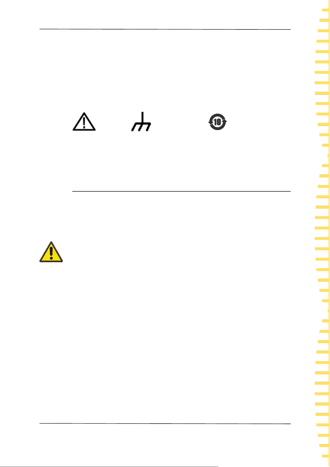
Safety signs on the product:
Warning
Shell grounding
terminal
Environmental protection usage
period identification
1.3 Measurement category
Measurement category
This instrument can be used for measurement under class I.
Warning:
This instrument is only allowed to be used in the specified measurement
class.
Measurement class definition
⚫ Class I refers to measurements taken on a circuit not directly connected to
the main power supply. For example, measurements made on circuits that
are not exported from a main power supply, especially from a protected
(internal) main power supply. In the latter case, the instantaneous stress will
change. Therefore, the user should understand the instantaneous capacity of
the instrument.

Safety requirement
EN
HBT4000 series user manual Copyright © Qingdao Hantek Electronic Co., LTD
4
⚫ Class II refers to measurements taken on a circuit directly connected to low-
voltage instruments. For example, measurements made on household
appliances, portable tools, and similar equipment.
⚫ Class III refers to measurements taken on construction equipment. For
example, measurements made on switchboards, circuit breakers, circuits
(including cables, busbars, junction boxes, switches, sockets) in fixed
equipment, as well as equipment for industrial use and certain other
equipment (for example, fixed motors permanently connected to fixed
instruments).
⚫ Class IV refers to measurements taken at the source of low-voltage
equipment. For example, measurements made on electricity meters, primary
overcurrent protection equipment, and pulse control units.
1.4 Ventilation Requirement
To ensure sufficient ventilation, when using the instrument in a workbench or
rack, please ensure that there is a gap of at least 10 centimeters on both sides,
above, and behind it.
Note:
Poor ventilation can cause an increase in instrument temperature, leading to
instrument damage. Good ventilation should be maintained during use, and
ventilation openings should be regularly checked.
Safety requirement
EN
Copyright © Qingdao Hantek Electronic Co., LTD HBT4000 series user manual
5
1.5 Work Environment
Operating temperature and humidity range
0 ℃ -40 ℃, below 80% RH (without condensation)
Storage temperature and humidity range
-10 ℃ -50 ℃, below 80% RH (without condensation)
Accuracy assurance temperature and humidity range
23 ° C ± 5 ° C, below 80% RH (without condensation)
Warning:
To avoid the risk of short circuits or electric shock inside the instrument, do
not operate the instrument in a damp environment.
Altitude
Operating and Non-operating: 2,000m.
This product is powered by mains conforming to installation (overvoltage)
category II.
Warning:
Ensure that no overvoltage (e.g. from lightning) reaches the product.
Otherwise, the operator may be in danger of receiving electric shock.
Installation (Overvoltage) Category Definitions.
Installation (overvoltage) category I refers to the signal level, which is suitable
for measuring terminals connected to equipment in the source circuit, where
measures have been taken to limit instantaneous voltage to the corresponding

Safety requirement
EN
HBT4000 series user manual Copyright © Qingdao Hantek Electronic Co., LTD
6
low level.
Installation (overvoltage) category II refers to the local distribution level, which
is suitable for equipment connected to the mains (AC power supply).
Pollution Degree
Pollution Degree 2
Pollution Degree Definition
⚫ Pollution Degree 1: No pollution or only dry, nonconductive pollution
occurs. The pollution has no effect. For example, a clean room or air-
conditioned office environment.
⚫ Pollution Degree 2: Normally only nonconductive pollution occurs.
Temporary conductivity caused by condensation is to be expected. For
example, indoor environment.
⚫ Pollution Degree 3: Conductive pollution or dry nonconductive pollution
that becomes conductive due to condensation occurs. To be found in
industrial environment or construction sites (harsh environments). For
example, sheltered outdoor environment.
⚫ Pollution Degree 4: The pollution generates persistent conductivity caused
by conductive dust, rain, or snow. For example, outdoor areas.
Security level
Class 1 - Grounded products

Safety requirement
EN
Copyright © Qingdao Hantek Electronic Co., LTD HBT4000 series user manual
7
1.6 Care and Cleaning
Care:
When storing or placing the internal resistance tester, do not expose the LCD
display to direct sunlight for a long time.
Cleaning:
According to the requirements of operating conditions, regularly check the
internal resistance tester and test line. Please clean the outer surface of the
instrument according to the following steps:
1) Use a lint free cloth to remove floating dust from the outside of the internal
resistance tester and test line. Please be extremely careful to avoid scratching the
smooth display filter material.
2) Clean the internal resistance tester with a soft cloth soaked in water. To clean
more thoroughly, a water solvent of 75% isopropanol can be used.
Note:
To avoid damaging the surface of the internal resistance tester or test line, do
not use any corrosive or chemical cleaning agents.
Warning:
Before re powering on, please confirm that the instrument has dried thoroughly
to avoid electrical short circuits or even personal injury caused by moisture.

Safety requirement
EN
HBT4000 series user manual Copyright © Qingdao Hantek Electronic Co., LTD
8
1.7 Environmental precautions
The following symbols indicate that this product complies with the requirements
established by WEEE Directive 2002/96/EC.
Equipment recycling:
The production of this equipment requires the extraction and utilization of natural
resources. If the scrapping of this product is not handled properly, certain
substances contained in the equipment may be harmful to the environment or
human health. To avoid the release of harmful substances into the environment
and reduce the use of natural resources, it is recommended to use appropriate
methods to recycle this product to ensure that most materials can be correctly
reused.

Product features
EN
Copyright © Qingdao Hantek Electronic Co., LTD HBT4000 series user manual
9
2 Product features
Product features
⚫ The full range of voltage measurement covers:160 V/260
V/410V/1300V/1700V/2100V
⚫ Internal impedance measurement range:3 mΩ/30 mΩ/300 mΩ/3 Ω/30 Ω/300
Ω/3.9 kΩ
⚫ Using the AC 4-terminal method, impedance measurement is not affected by
the impedance of the test line
⚫ Resistance minimum resolution 0.1μΩ, minimum voltage resolution 1μV
⚫ It has independent comparison functions for resistance and voltage, while
displaying the internal resistance and voltage of the battery
⚫ Short circuit zeroing function to remove bias voltage of the instrument or
errors caused by measurement environment
⚫ Supports USB data storage and screenshot saving functions, and can upgrade
instrument programs through USB drives
⚫ Calculate various statistical indicators, including but not limited to mean,
maximum, minimum, standard deviation, etc., and easily draw a normal
distribution map
⚫ Standard RS232/485, LAN, EXT I/O, USB Host, ANALOG OUTPUT, USB Device
interface, optional GPIB interface
⚫ Sampling rate: Slow/Horotelic/Fast, capable of high-speed measurement up
to approximately 40 ms
⚫ Voltage calibration and resistance calibration, used to compensate for bias
voltage or gain drift in the internal circuit of the instrument
The HBT4000 series internal resistance tester is a battery internal resistance
tester with high precision, high resolution, and fast measurement characteristics.
Using the AC four terminal testing method to more accurately test the internal
resistance and voltage of the battery; 0.1μΩ Resistance resolution, minimum
voltage resolution 1μV. Ensure the credibility of the measurement; Built in
comparator function to automatically determine whether battery parameters
meet standards; Built in multiple high-speed communication interfaces, suitable
for more testing scenarios; Easy to operate, precise and fast, stable and reliable,
this battery internal resistance tester will be your best choice.

Overview
EN
HBT4000 series user manual Copyright © Qingdao Hantek Electronic Co., LTD
10
3 Overview
This document is used to guide users to quickly understand the front and rear
panels, user interface, and basic operating methods of the HBT4000 series
internal resistance tester.
Tip:
The latest version of this manual can be downloaded at
(https://www.hantek.com).
Document number:202312
Software version:
Software upgrade may change or increase product functionalities, please pay
attention to Hantek website for the latest version.
Document format conventions:
1 button
Use "square brackets+text (bold)" to represent the front panel buttons, for
example, [Utility] represents the "Utility" button.
2 menus
Use "menu text (bold)+blue" to represent a menu option, such as "other" to click
on the "other" option on the current operating interface of the instrument and
enter the "other" function configuration menu。
3 Operation steps
Use "->" to represent the next step. For example, [Utility] -> Other means click

Overview
EN
Copyright © Qingdao Hantek Electronic Co., LTD HBT4000 series user manual
11
Utility label before clicking Other menu.
4 Button icon
Icon
Button
Icon
Button
Direction keys
Screenshot key
Confirm key
Menu softkeys
Table 3-1 Button
Document content agreement:
The HBT4000 series internal resistance tester includes the following models.
Unless otherwise specified, this manual uses HBT4563H as an example to explain
the HBT4000 series and its basic operations.
Model
Resistance
resolution
Voltage
resolution
Measuring
range
Interface
HBT4561A
0.1μΩ
1μV
0~3.9kΩ/
0~160V
RS232/485,USB,LAN,I
O,ANALOG OUTPUT
HBT4561H
0.1μΩ
1μV
0~3.9kΩ/
0~160V
RS232/485,USB,LAN,I
O,ANALOG
OUTPUT,GPIB
HBT4562A
0.1μΩ
1μV
0~3.9kΩ/
0~260V
RS232/485,USB,LAN,I
O,ANALOG OUTPUT
HBT4562H
0.1μΩ
1μV
0~3.9kΩ/
RS232/485,USB,LAN,I

Overview
EN
HBT4000 series user manual Copyright © Qingdao Hantek Electronic Co., LTD
12
Model
Resistance
resolution
Voltage
resolution
Measuring
range
Interface
0~260V
O,ANALOG
OUTPUT,GPIB
HBT4563A
0.1μΩ
1μV
0~3.9kΩ/
0~410V
RS232/485,USB,LAN,I
O,ANALOG OUTPUT
HBT4563H
0.1μΩ
1μV
0~3.9kΩ/
0~410V
RS232/485,USB,LAN,I
O,ANALOG
OUTPUT,GPIB
HBT4564A
0.1μΩ
10μV
0~3.9kΩ/
0~1300V
RS232/485,USB,LAN,I
O,ANALOG OUTPUT
HBT4564H
0.1μΩ
10μV
0~3.9kΩ/
0~1300V
RS232/485,USB,LAN,I
O,ANALOG
OUTPUT,GPIB
HBT4565A
0.1μΩ
10μV
0~3.9kΩ/
0~1700V
RS232/485,USB,LAN,I
O,ANALOG OUTPUT
HBT4565H
0.1μΩ
10μV
0~3.9kΩ/
0~1700V
RS232/485,USB,LAN,I
O,ANALOG
OUTPUT,GPIB
HBT4566A
0.1μΩ
10μV
0~3.9kΩ/
0~2100V
RS232/485,USB,LAN,I
O,ANALOG OUTPUT

Overview
EN
Copyright © Qingdao Hantek Electronic Co., LTD HBT4000 series user manual
13
Model
Resistance
resolution
Voltage
resolution
Measuring
range
Interface
HBT4566H
0.1μΩ
10μV
0~3.9kΩ/
0~2100V
RS232/485,USB,LAN,I
O,ANALOG
OUTPUT,GPIB
Table 3-2 Model Table

Quick Start
EN
HBT4000 series user manual Copyright © Qingdao Hantek Electronic Co., LTD
14
4 Quick Start
4.1 General inspection
Check transportation packaging
After receiving the internal resistance tester, the user should check the equipment
according to the following steps: check whether there is any damage caused by
transportation: if the packaging carton or foam plastic protective pad is seriously
damaged, please keep it until the whole machine and accessories pass the
electrical and mechanical tests.
Check attachments
The details of the provided attachments are explained in Appendix A: Models and
Accessories at the end of this manual. If missing or damaged attachments are
found, please contact the dealer responsible for this business.
Inspect the entire machine
If you find that the appearance of the instrument is damaged, the instrument is
not working properly, or it fails the performance test, please contact the dealer
responsible for this business.
Quick Start
EN
Copyright © Qingdao Hantek Electronic Co., LTD HBT4000 series user manual
15
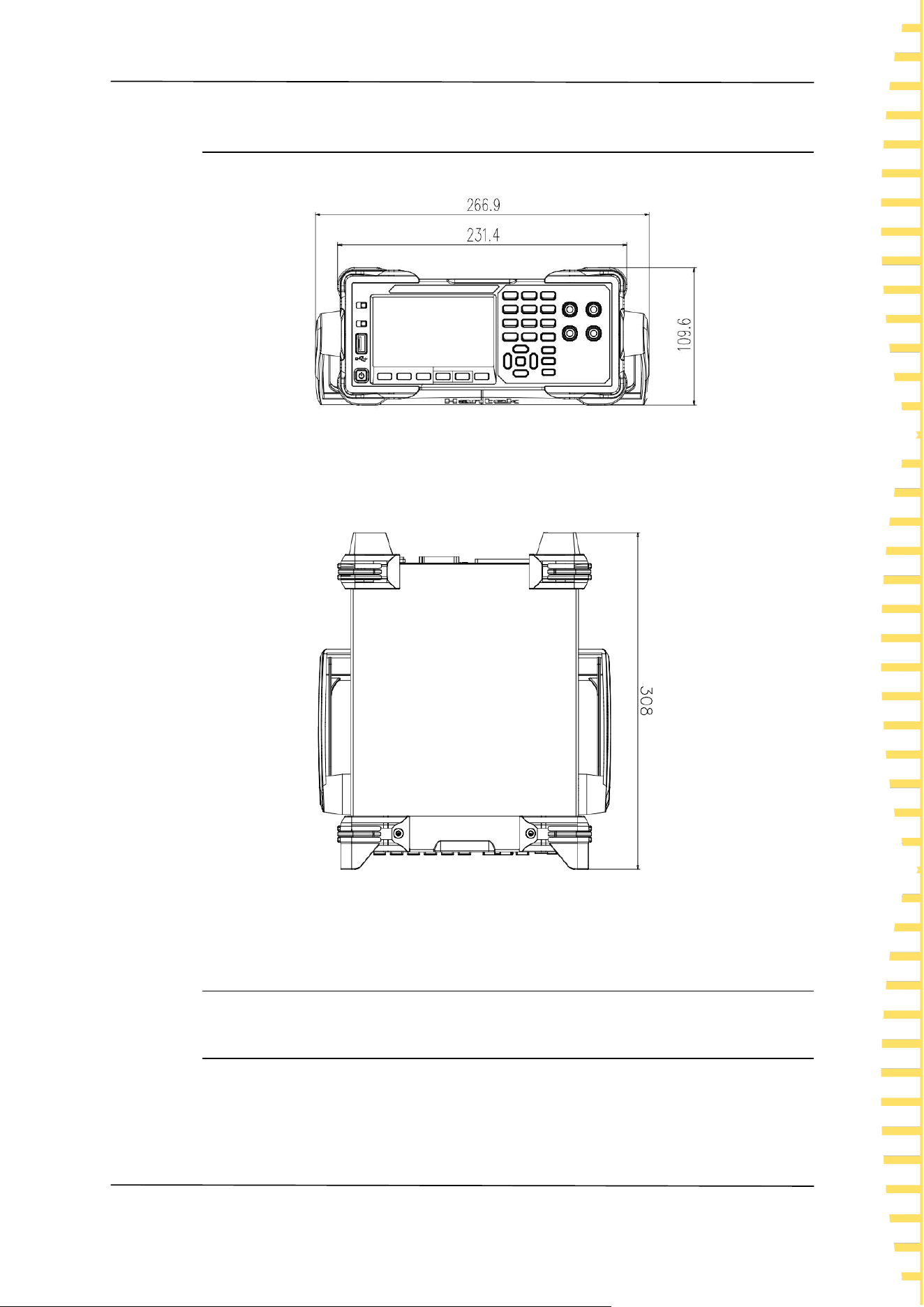
4.2 Appearance dimensions
Figure 4-1Front view
Figure 4-2 vertical view
4.3 Preparation before use
4.3.1 Connecting the power supply
This series of internal resistance testers can input AC power with specifications of
Quick Start
EN
HBT4000 series user manual Copyright © Qingdao Hantek Electronic Co., LTD
16
90-240 VAC, 47/63Hz, and 30VA. Please connect the internal resistance tester to
the power supply using the power cord provided in the attachment. Press the
power switch in the lower left corner of the front panel to turn on the
instrument. If the instrument is not turned on, please confirm that the power
cord is securely connected and ensure that the instrument is connected to a
powered power source.
Warning:
To avoid electric shock, please ensure that the instrument is properly
grounded.
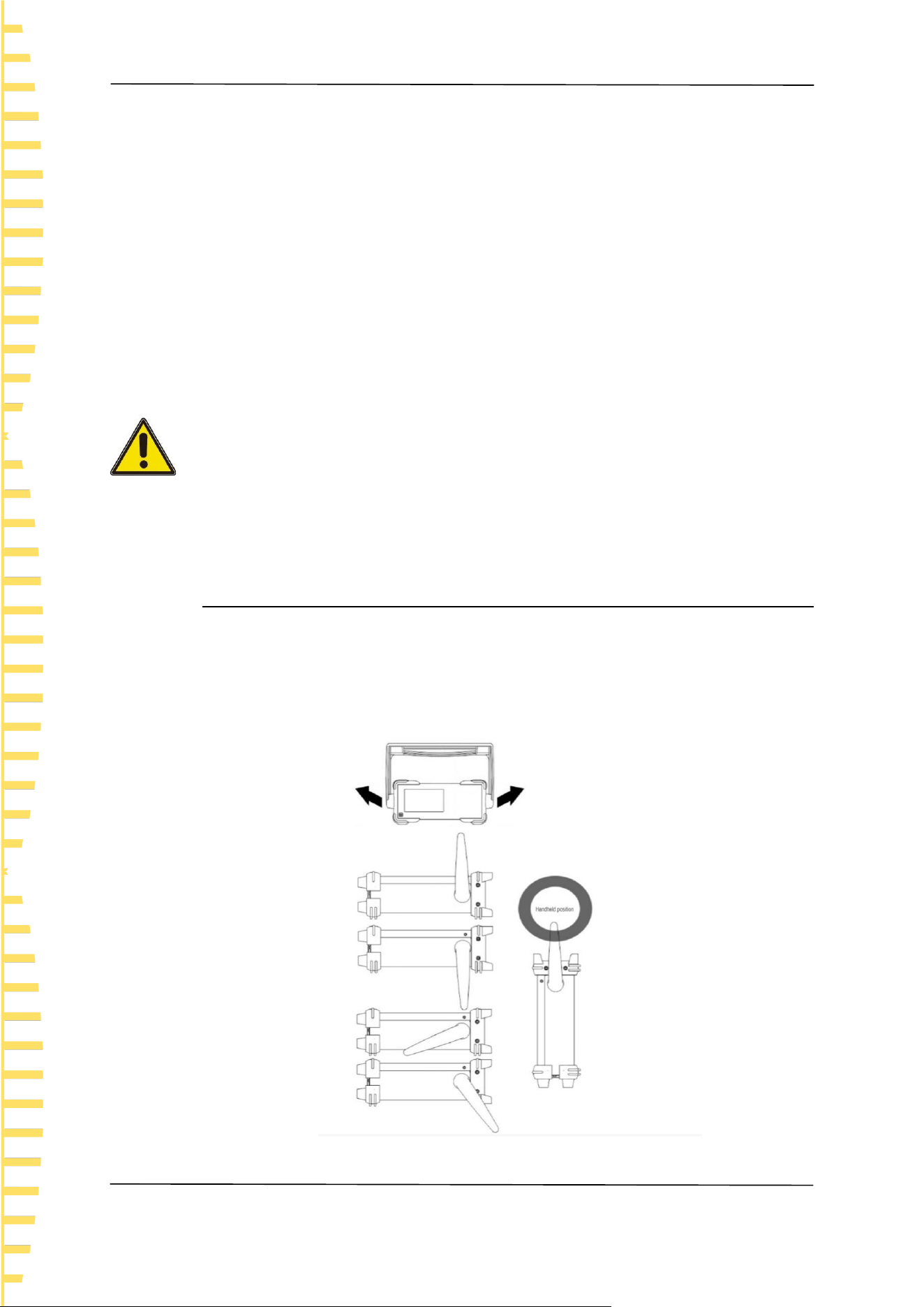
4.3.2 Adjusting the handle
To adjust the handle of the instrument, hold the handles on both sides of the
instrument and pull them outward, then rotate the handles.
Figure 4-3 Handheld position
Quick Start
EN
Copyright © Qingdao Hantek Electronic Co., LTD HBT4000 series user manual
17
4.3.3 Setting System Language
The internal resistance tester supports both Chinese and English menus, and
provides corresponding help information, prompt information, and interface
display.
Press [Utility] ->Other ->English to select the desired language. When selecting
"Chinese" or "English", the menu, help information, prompt messages, and
interface are displayed in Chinese or English, respectively.
4.4 Product Introduction
This chapter introduces the front and rear panels and user interface of the
internal resistance tester.
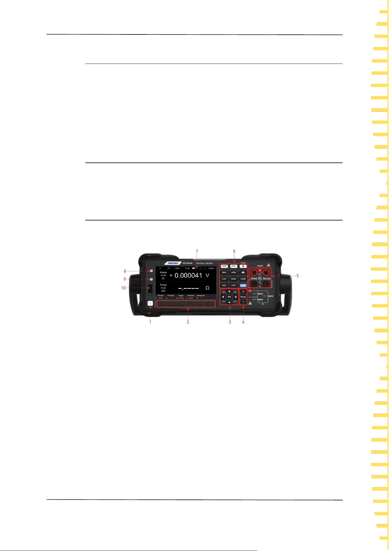
4.4.1 Introduction to Front Panel
Figure 4-4 Front Panel
1 Key switch
2 Menu soft keys
Corresponding to the menu above it one by one, press any soft key to activate the
corresponding menu.
3 Directional keys (up/down/left/right), confirm key
Direction keys: used to select keyboard numbers or modify parameters; Confirm
key: Confirm the selected parameter.
4 Plus keys, range keys, and minus keys
5 Input ports
6 Function keys
⚫ [COMP]: Comparator function menu.
⚫ [STAT]: Statistics function menu.
⚫ [Local]: Lock/unlock the keyboard; Local remote control key.
Quick Start
EN
HBT4000 series user manual Copyright © Qingdao Hantek Electronic Co., LTD
18
⚫ [MEA]: Measurement function menu.
⚫ [VIEW]: System information menu.
⚫ [0 ADJ]: Zero adjustment key.
⚫ [SAVE]: Save key.
⚫ [LOAD]: Load key.
⚫ [ESC]:Escape key.
⚫ [Utility]: Auxiliary function keys.
⚫ [TRIG]: Trigger key.
⚫ : Screenshot key.
7 LCD display screen
4.3-inch color TFT LCD display screen, displaying the menu and parameter
settings of current functions, system status, and prompt messages.
8 Restore default settings
Used to restore the instrument status to the factory default values.
9 Help
To obtain contextual help information for any front panel buttons or menu soft
keys, press the key and then press the button that you need help for.
10 USB HOST interface
Can be connected to external storage devices (USB drives) for saving or loading
settings files, etc.
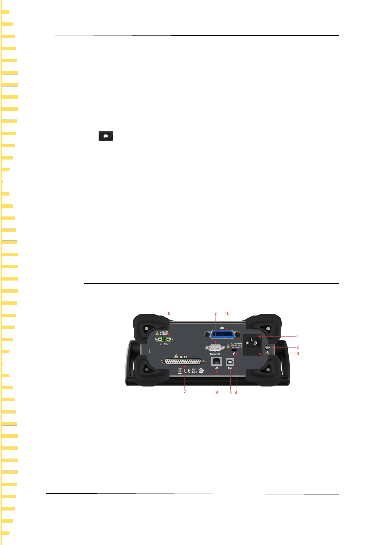
4.4.2 Introduction to Rear Panel
Figure 4-5 Rear Panel
1 AC power socket
2 Shell grounding terminal
3 Fuse holder
4 Safety lock holes
5 USB DEVICE interface
6 LAN interface
Quick Start
EN
Copyright © Qingdao Hantek Electronic Co., LTD HBT4000 series user manual
19
7 EXT I/O interface
8 ANALOG OUTPUT interface
9 RS-232/485 interface
10 GPIB interface
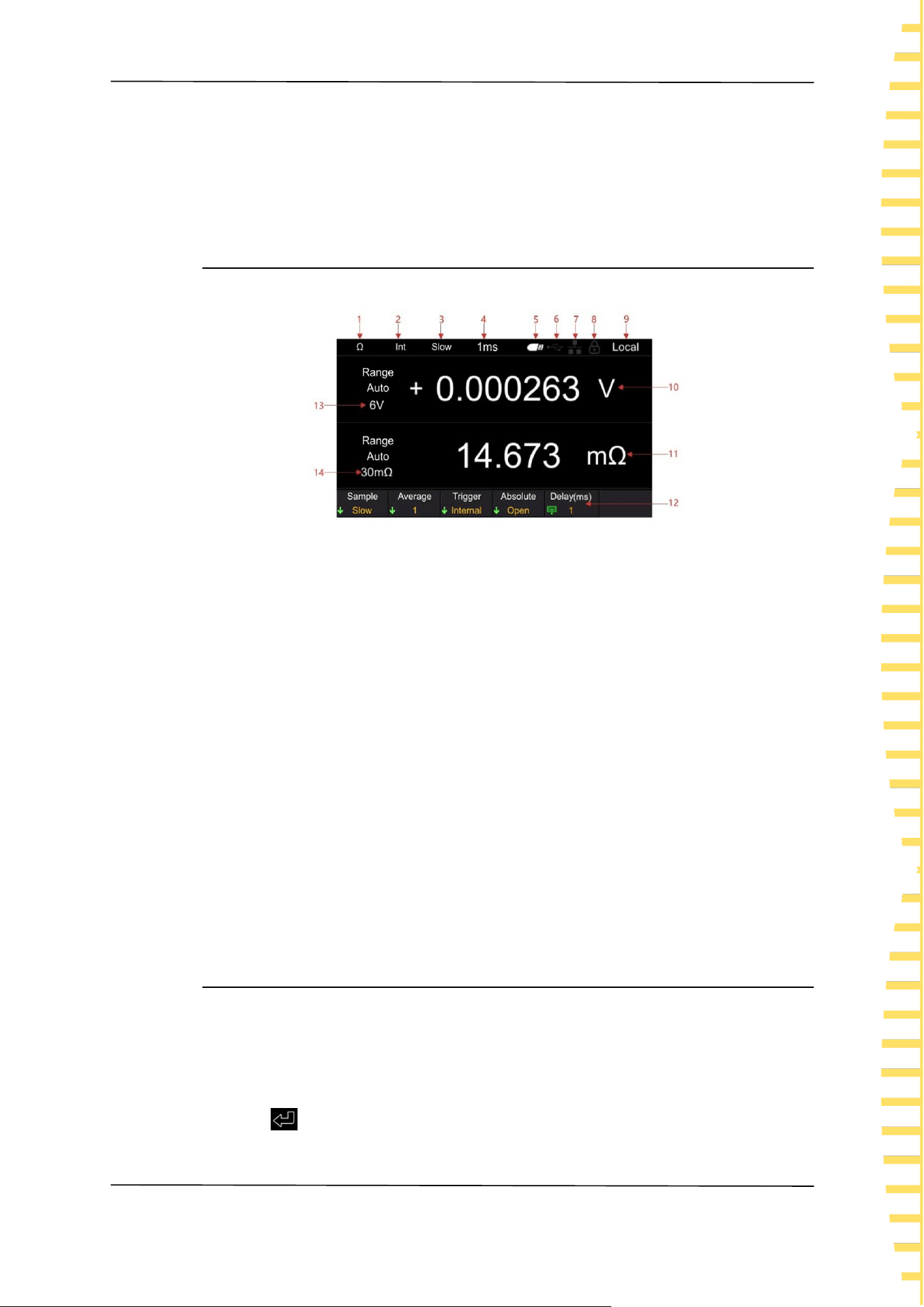
4.4.3 User Interface Introduction
Figure 4-6 User Interface
1 Range Quick Identification
2 Trigger sources
3 Sampling rates
4 Delay
5 USB icon display
6 USB device icon display
7 Network icon display
8 lock screen icons
9 Local/Remote Display
10 Voltage measurement values
11 Resistance measurement value
12 Auxiliary menu bar
13 Resistance range
14 Voltage range
4.5 Set parameter values
The parameter settings of this series of internal resistance testers support numeric
keyboard input. Parameter settings can be completed by left clicking, right
clicking, and confirmation keys. Move the cursor position by clicking the left and
right buttons, and click the confirm button [OK] to input. Move the cursor to the
enter key , then click [OK] to save and exit.

Quick Start
EN
HBT4000 series user manual Copyright © Qingdao Hantek Electronic Co., LTD
20
Figure 4-7 Keypad
Note: If no settings are made on the numeric keyboard interface for more than 30
seconds, the instrument will automatically jump to the measurement display
interface.
4.6 Using the built-in help system
To obtain help information for any front panel buttons or menu soft keys, on the
measurement display interface, press the [?] button on the front panel, and then
press the button you need help with to obtain the operation prompt for that
button. Press the [?] button again to exit the help system.
Start using
EN
Copyright © Qingdao Hantek Electronic Co., LTD HBT4000 series user manual
21
5 Start using
⚫ To prevent electric shock accidents, please do not short circuit the top of
the test line and the line with voltage.
⚫ Do not measure AC voltage, AC current, or DC current. Otherwise, it may
cause instrument damage or personal injury accidents.
⚫ To prevent electric shock, please confirm the rated value of the test wire
before measurement, and do not measure voltage higher than the rated
value.
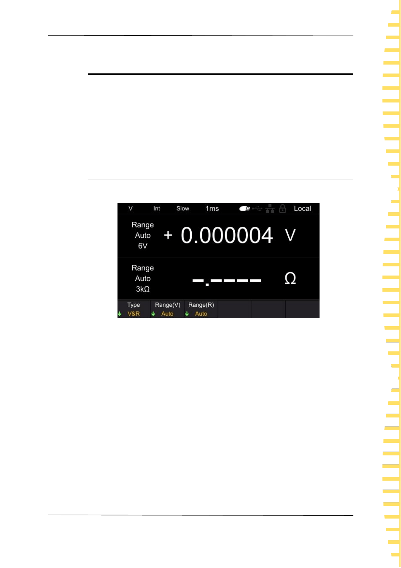
5.1 Measurement Settings
Click the [Range] button to enter the measurement display interface.
Figure 5-1 Measurement display interface
Note: If no settings are made in other interfaces (except the calibration interface)
for more than 30 seconds, the instrument will automatically jump to the
measurement display interface.
5.1.1 Setting Type
Click the Type menu soft key to select categories such as V&R, Voltage, and
Resistance.
V&R: Simultaneously measure and display voltage and resistance, as shown in
Figure 5-1.
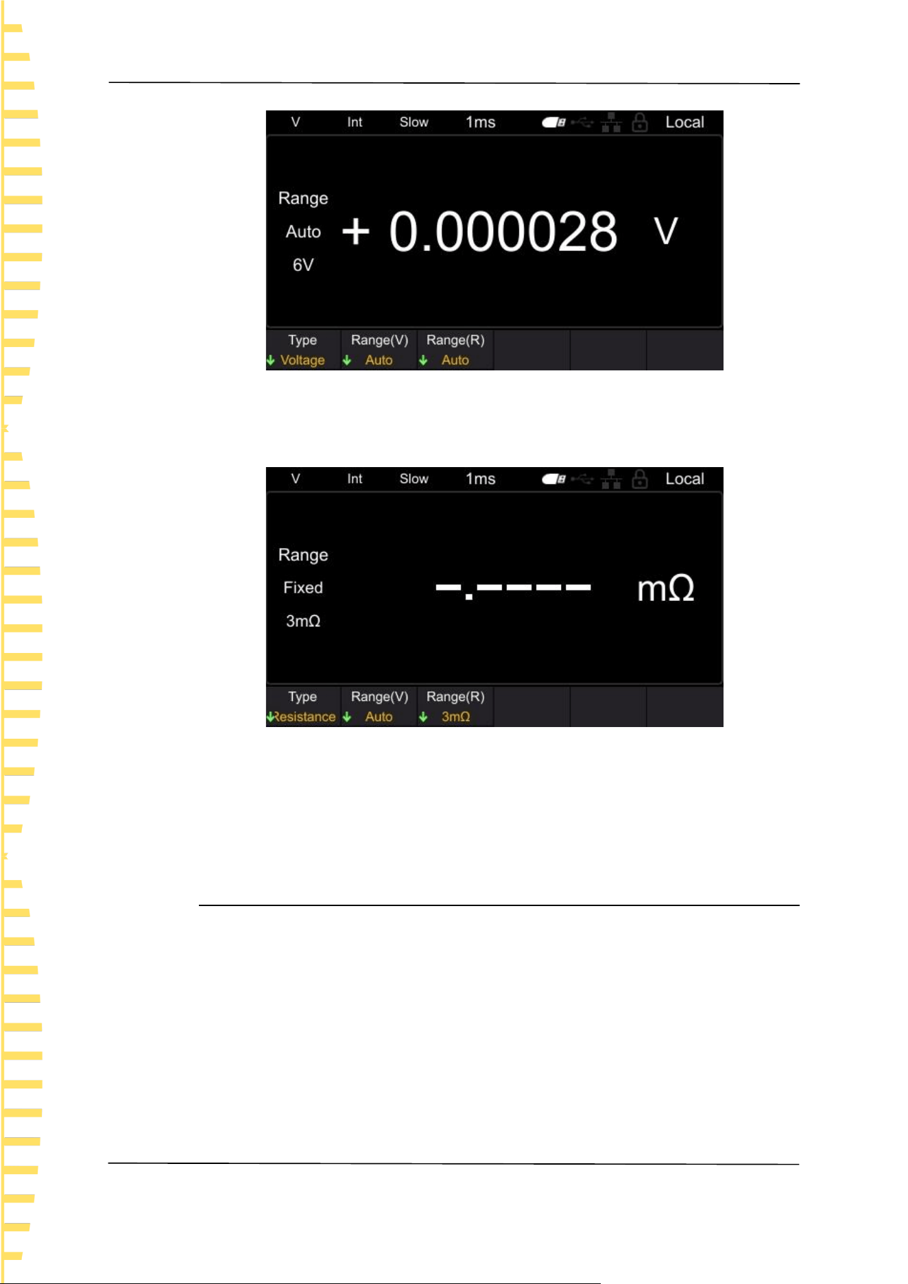
Voltage: Measure and display the voltage value, as shown in the following figure.
Start using
EN
HBT4000 series user manual Copyright © Qingdao Hantek Electronic Co., LTD
22
Figure 5-2 Measurement voltage interface
Resistance: Measure and display the resistance value, as shown in the following
figure.
Figure 5-3 Measurement resistance interface
Note: When measuring resistance or voltage separately, if the measurement type
is set to resistance function or voltage function, faster measurements can be
made.
5.1.2 Set voltage range
This instrument (HBT4563H) has selectable voltage ranges of 6V, 60V, 410V, and
Auto. Automatic refers to the instrument automatically selecting the appropriate
voltage range.
1 Press the [Range] key to enter the measurement page;
2 Click on the Range (V) menu soft key;
3 Use the menu soft key to select the range and complete the voltage range
setting.
In addition, the range can be switched using the plus minus keys, and automatic
cannot be selected when switching ranges using the plus minus keys.
Start using
EN
Copyright © Qingdao Hantek Electronic Co., LTD HBT4000 series user manual
23
Note: The automatic range may become unstable due to the measured value of
the object being at the critical range value. At this point, please manually specify
the range or extend the delay time.
If the plus and minus keys are pressed in automatic range mode, the automatic
range will be released in the current range and changed to manual range. The
automatic displayed on the screen will become fixed.
5.1.3 Setting the Resistance Range
The resistance ranges available for this series of internal resistance testers include
3m Ω, 30 m Ω, 300 m Ω, 3 Ω, 30 Ω, 300 Ω, 3900 Ω, and Auto. Automatic refers
to the instrument automatically selecting the appropriate resistance range.
1 Press the [Range] key to enter the measurement page;
2 Click on the Range (R) menu soft key;
3 Use the menu soft key to select the range and complete the setting of the
resistance range.
In addition, the range can be switched using the plus minus keys, and automatic
cannot be selected when switching ranges using the plus minus keys.
Note: The automatic range may become unstable due to the measured value of
the object being at the critical range value. At this point, please manually specify
the range or extend the delay time.
If the plus and minus keys are pressed in automatic range mode, the automatic
range will be released in the current range and changed to manual range. The
automatic displayed on the screen will become fixed.
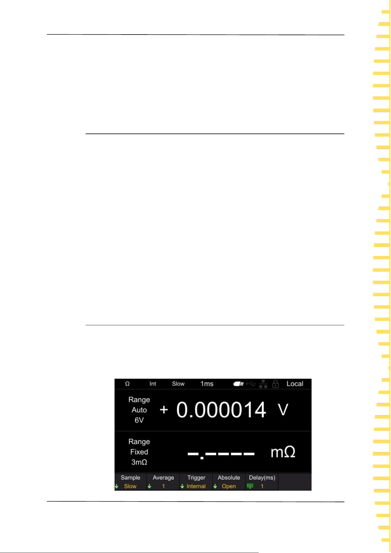
5.1.4 Setting the sampling rate
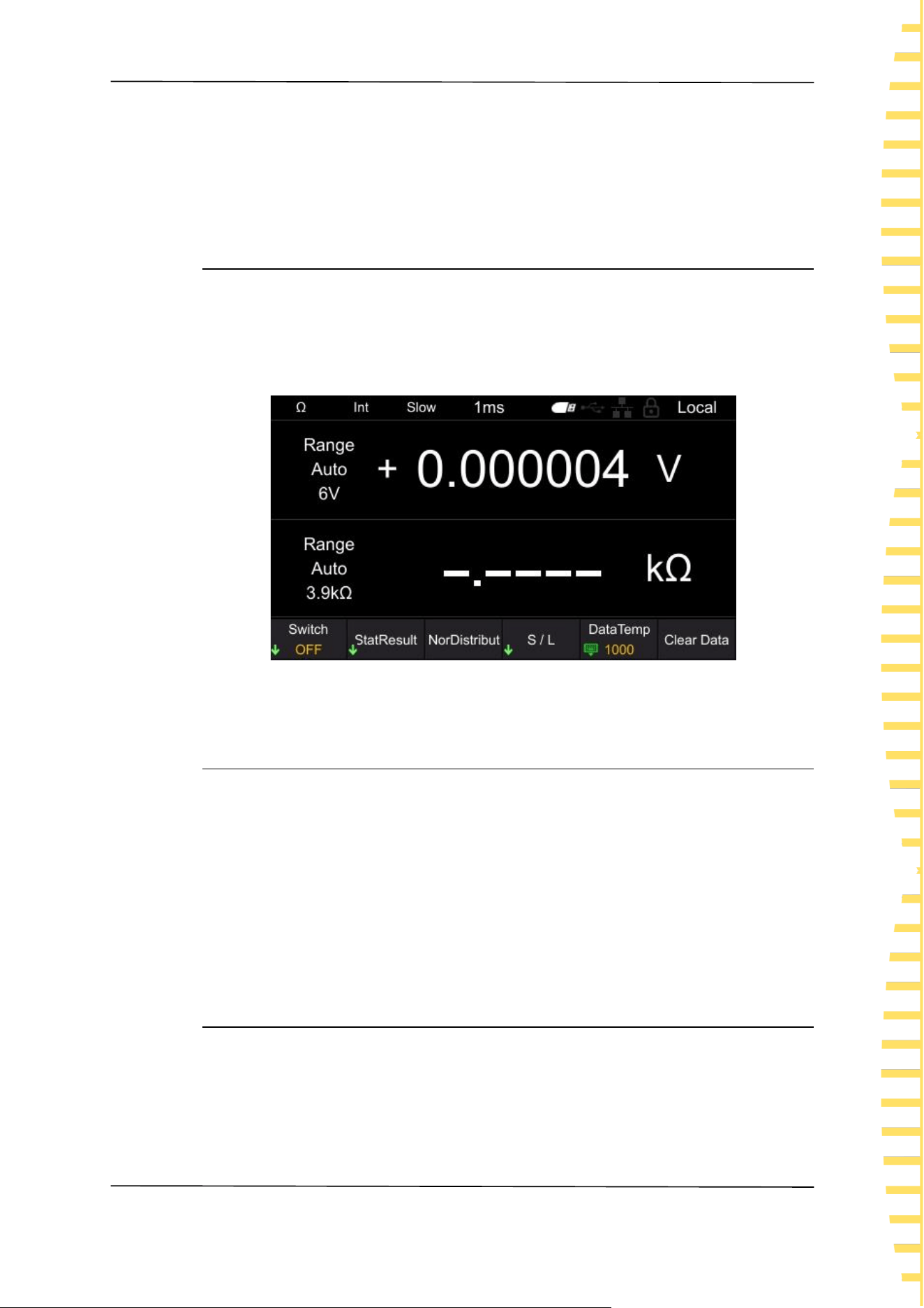
Click the [MEA] button to enter the measurement display interface, as shown in
the following figure. Click on the Sample again, and the selectable gears are:
Slow, Horotelic and Fast.Use the menu soft key to select the desired rate gear to
complete the sampling rate setting.
Start using
EN
HBT4000 series user manual Copyright © Qingdao Hantek Electronic Co., LTD
24
Figure 5-4 Measurement display interface
5.2 Zeroing
To eliminate errors caused by the bias voltage of the instrument itself or the
measurement environment, please perform zero adjustment before measurement.
The measurement accuracy is specified after zeroing. Zero adjustment can also be
performed on the 0ADJ terminal of EXT I/O.
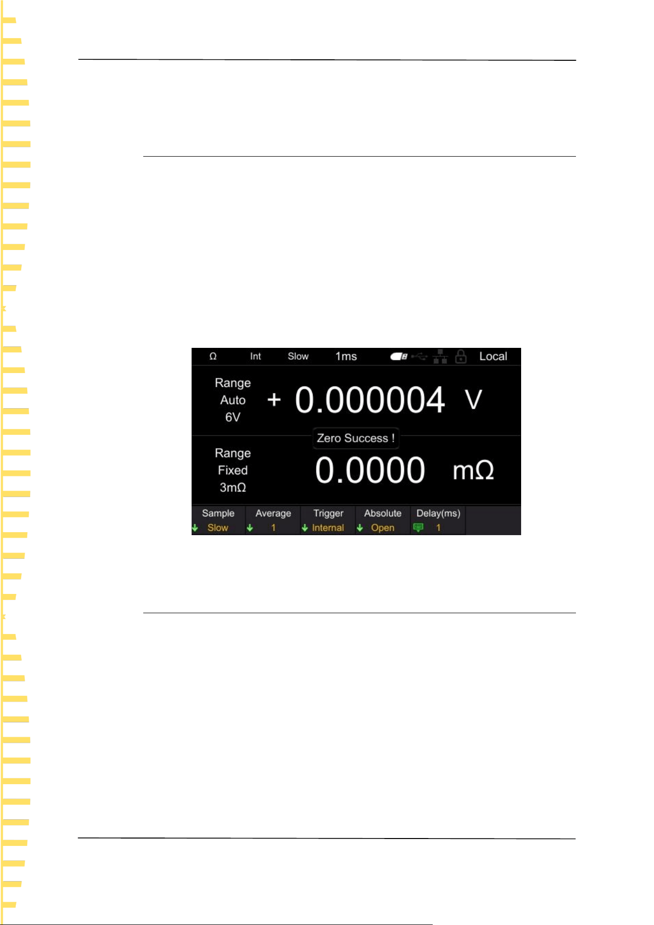
Click on the [0 ADJ] key, or click on [Utility] ->Cal in sequence. After entering the
password, click on the [0 ADJ] soft key to execute zero adjustment. After
successful zero adjustment, the interface will pop up as shown in the following
figure. If zero adjustment fails, please check if the short circuit is correct, and then
perform zero adjustment until successful.
Figure 5-5 Zeroing
5.3 Test abnormal output
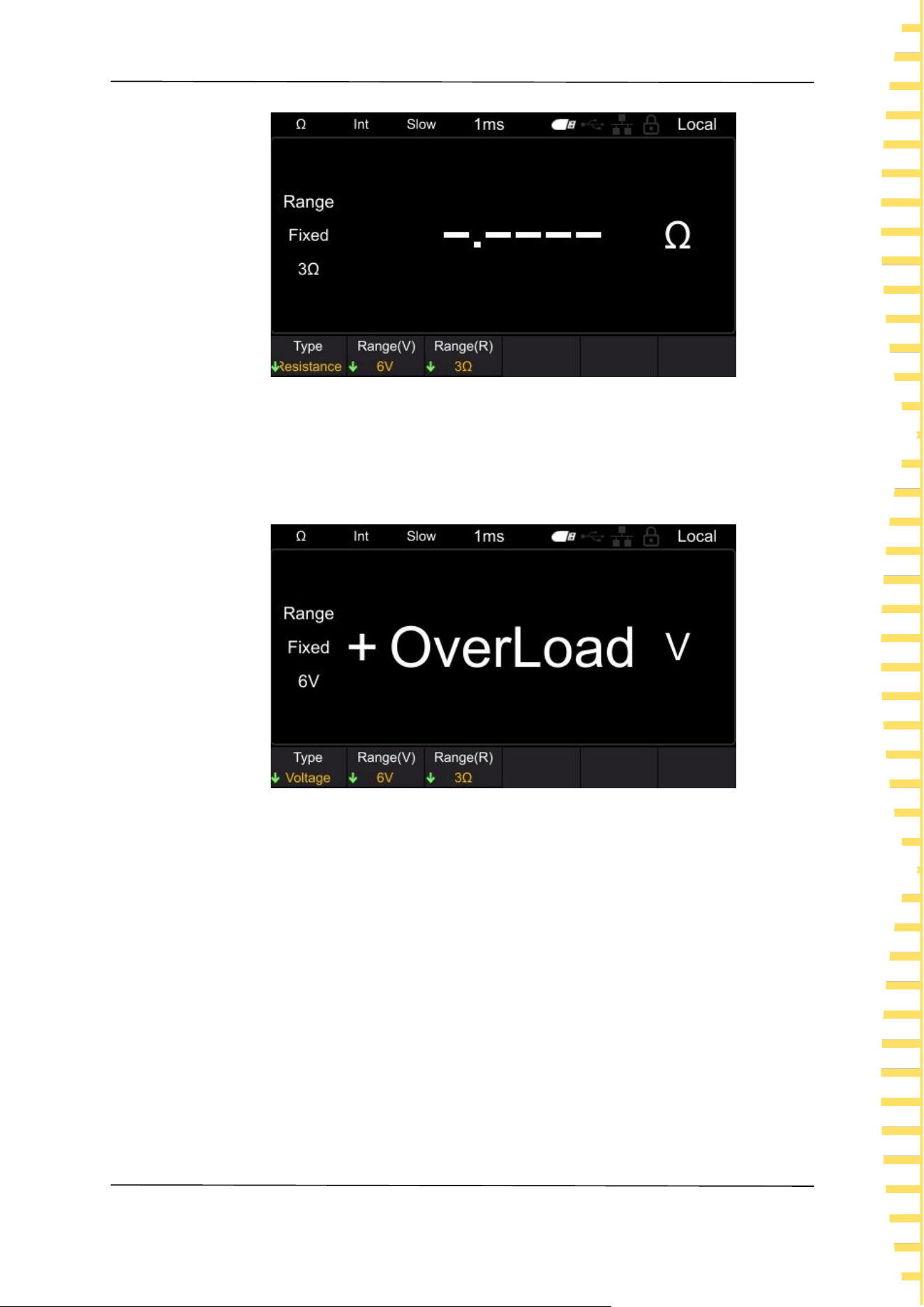
⚫ When the test line is not connected to the test object, [------] is displayed on
the screen, as shown in the following figure. In addition, an abnormal test
signal (ERR) will be output from the EXTI/O terminal.
Start using
EN
Copyright © Qingdao Hantek Electronic Co., LTD HBT4000 series user manual
25
Figure 5-6 Test exception
⚫ When the resistance of the test object is greater than the range, [OverLoad] is
displayed on the screen, as shown in the following figure. In addition, an
abnormal test signal (ERR) will be output from the EXTI/O terminal.
Figure 5-7 Measure overflow
In addition, the following situations can also cause testing anomalies.
⚫ When the probe is disconnected
⚫ When the circuit protection fuse is disconnected
⚫ When the contact resistance is high or the wiring resistance is high due to
probe wear, dirt, etc
Note: If the contact resistance or wiring resistance is large, the measurement error
will increase.
Application measurement
EN
HBT4000 series user manual Copyright © Qingdao Hantek Electronic Co., LTD
26
6 Application measurement
6.1 Measurement Configuration
The measurement page has 5 test configurations: [Sample], [Average], [Trigger],
[Absolute] and [Delay].Below are the functions and setting methods of these
measurement configurations.
6.1.1 Setting the sampling rate
The sampling rate can be changed in three stages (Slow/Horotelic/Fast).The lower
the sampling rate, the higher the testing accuracy.
Steps for switching sampling rate:
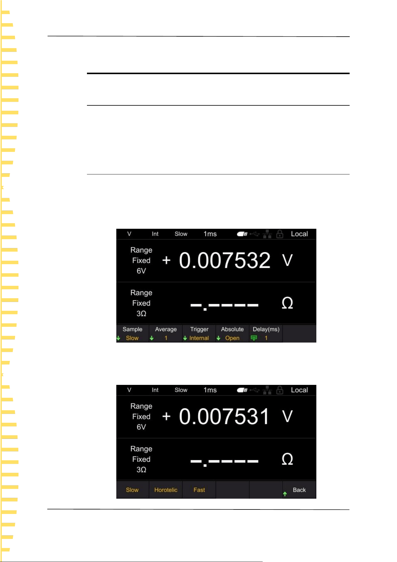
Click on the [MEA] button, and the display will be as follows:
Figure 6-1 Measurement display interface
Click on the Sample and it will display as follows. Press the corresponding soft
key again to complete setting the sampling rate.
Application measurement
EN
Copyright © Qingdao Hantek Electronic Co., LTD HBT4000 series user manual
27
Figure 6-2 Set sampling rate
6.1.2 Setting the average value
The average function refers to the function of outputting the average measured
value. By using this function, the deviation of the displayed value can be reduced.
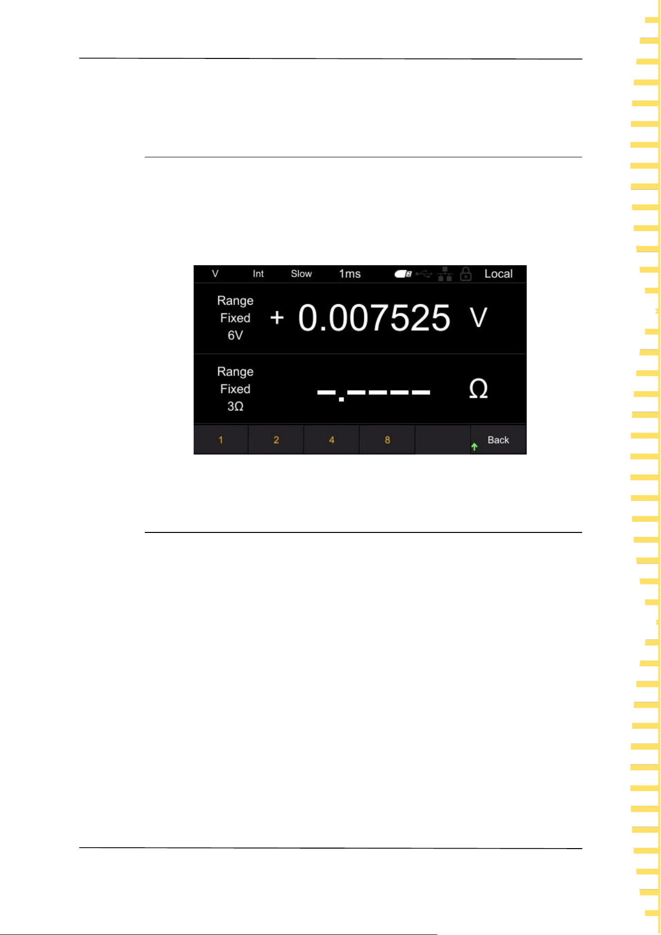
Click on [MEA] ->Average to set the average value. The average number of
choices is 1, 2, 4, and 8, as shown in the figure. The default setting is 1. Press the
corresponding soft key again to complete setting the average value.
Figure 6-3 Set average value
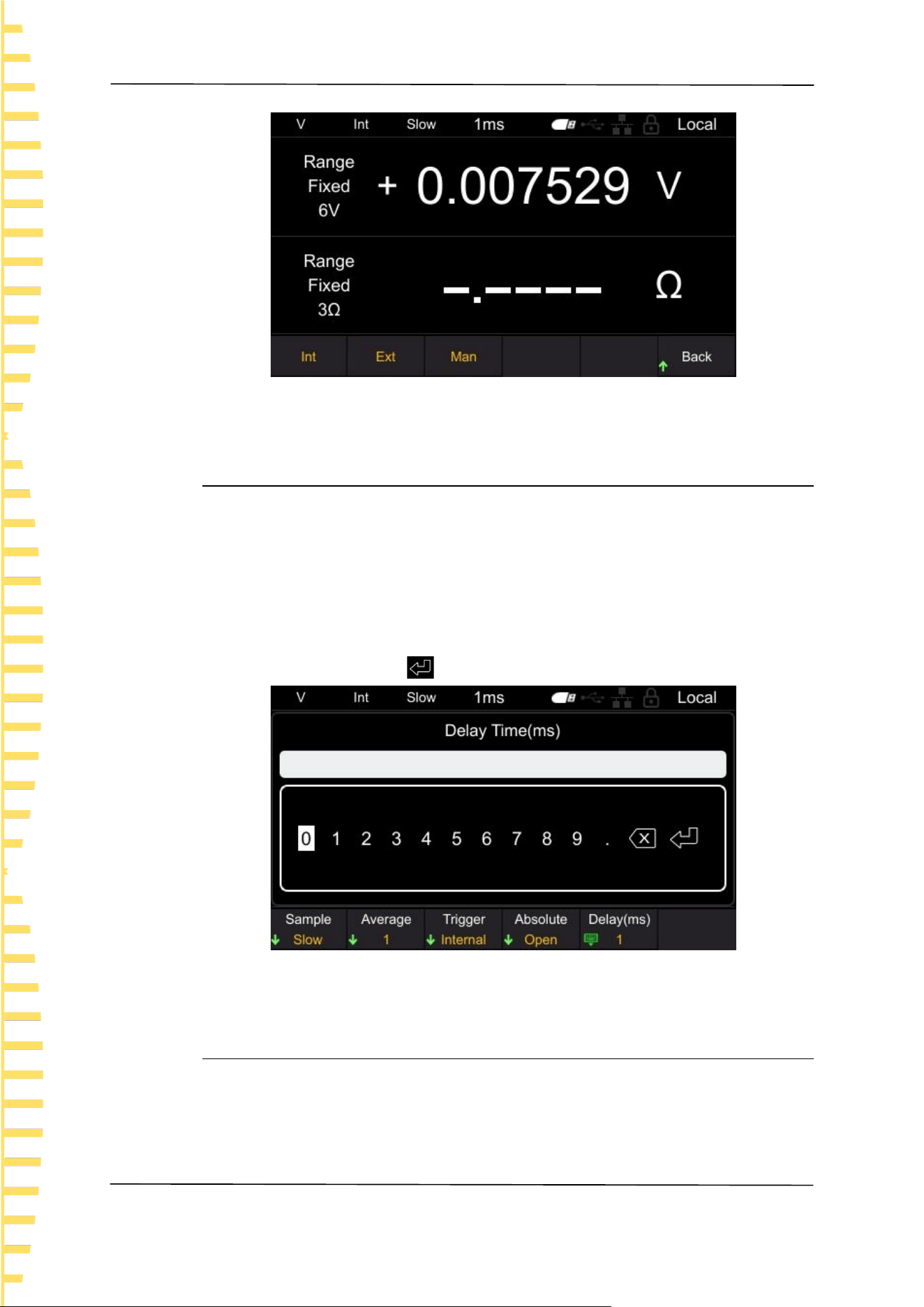
6.1.3 Trigger function
The trigger source function is used to set the trigger mode of the instrument.
Trigger sources include [Int], [Ext], and [Man].
Internal trigger: Automatically triggered internally (measured automatically).
External triggering: Measurement is carried out through external input triggering
signals. Set to external trigger, connect the TRIG terminal of the EXT I/O
connector on the rear panel to ISO_ COM short circuit, perform one
measurement.
Manual triggering: Measurement is carried out by manually inputting triggering
signals. Set to manual trigger, press the TRIG key to perform one measurement.
Click on [MEA] ->Trigger in sequence to set the trigger source, as shown in the
figure. Press the corresponding soft key again to complete the setting of the
trigger source. The default setting is Int.
Application measurement
EN
HBT4000 series user manual Copyright © Qingdao Hantek Electronic Co., LTD
28
Figure 6-4 Set trigger source
6.1.4 Delay function
Set the delay time from the input trigger signal to the start of measurement. If a
trigger signal is input immediately after connecting the test object, the
instrument will start measuring after the measurement value stabilizes by setting
a delay time. The adjustable delay range is 1ms~9999ms, with a default of 1ms.
Click on [MEA] ->Delay (ms) in sequence to set the delay time, as shown in the
figure. Move the cursor position by left and right clicking, and click [OK] to input.
Move the cursor to the key , then click [OK] to save and exit.
Figure 6-5 Setting Delay
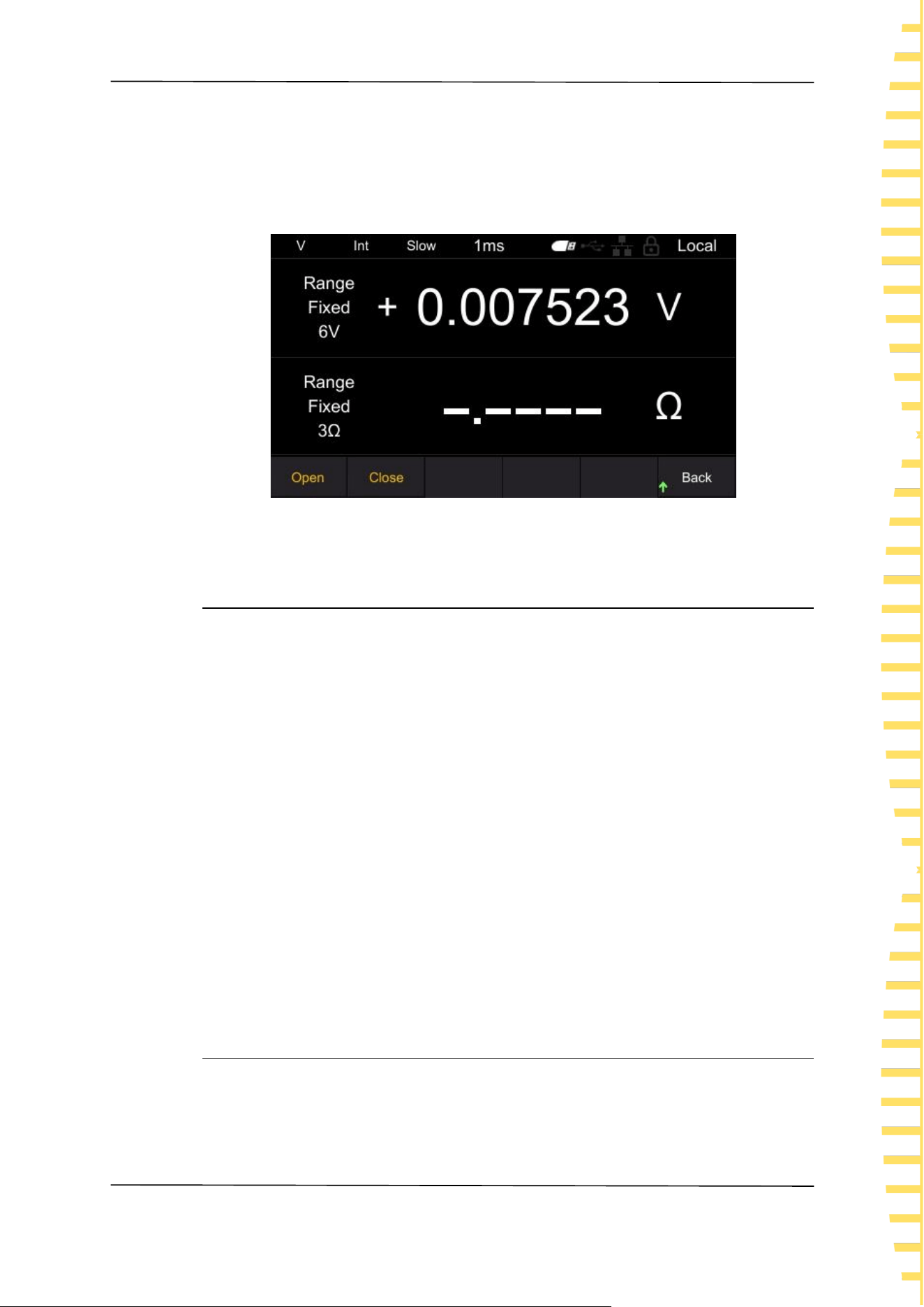
6.1.5 Absolute value function
The absolute value determination includes [Open] and [Close], and the absolute
value determination defaults to Open. After enabling this function, even if the
battery polarity is reversed, it can still be displayed as a positive value; If this
Application measurement
EN
Copyright © Qingdao Hantek Electronic Co., LTD HBT4000 series user manual
29
function is turned off, there is a possibility of negative measurement values, which
can affect the judgment of comparison results.
Click on [MEA] ->Absolute in sequence to set the absolute value, as shown in the
figure. Press the corresponding soft key again to complete the function of setting
absolute values.
Figure 6-6 Set absolute value function
6.2 Comparator function
The comparator function refers to the function of comparing pre-set critical values
with measured values, determining whether the measured values meet the
judgment criteria, and displaying and outputting them. The comparison methods
for thresholds include two methods: setting upper and lower limits, and setting
baseline values and percentages. As a comparator result, in addition to displaying
Hi, In, Lo pages and sounding the buzzer, it can also be output through the EXT
I/O terminal.
There are two comparison modes: Auto and Manual, with the default being Auto
mode.
Automatic mode: After setting to automatic mode and enabling the comparator
function, always output the comparison results of the comparator.
Manual mode: After setting to manual mode and enabling the comparator
function, the comparison result is only output when the MANU input of EXT I/O is
on.
Note: When the comparator is turned on, automatic range cannot be used.
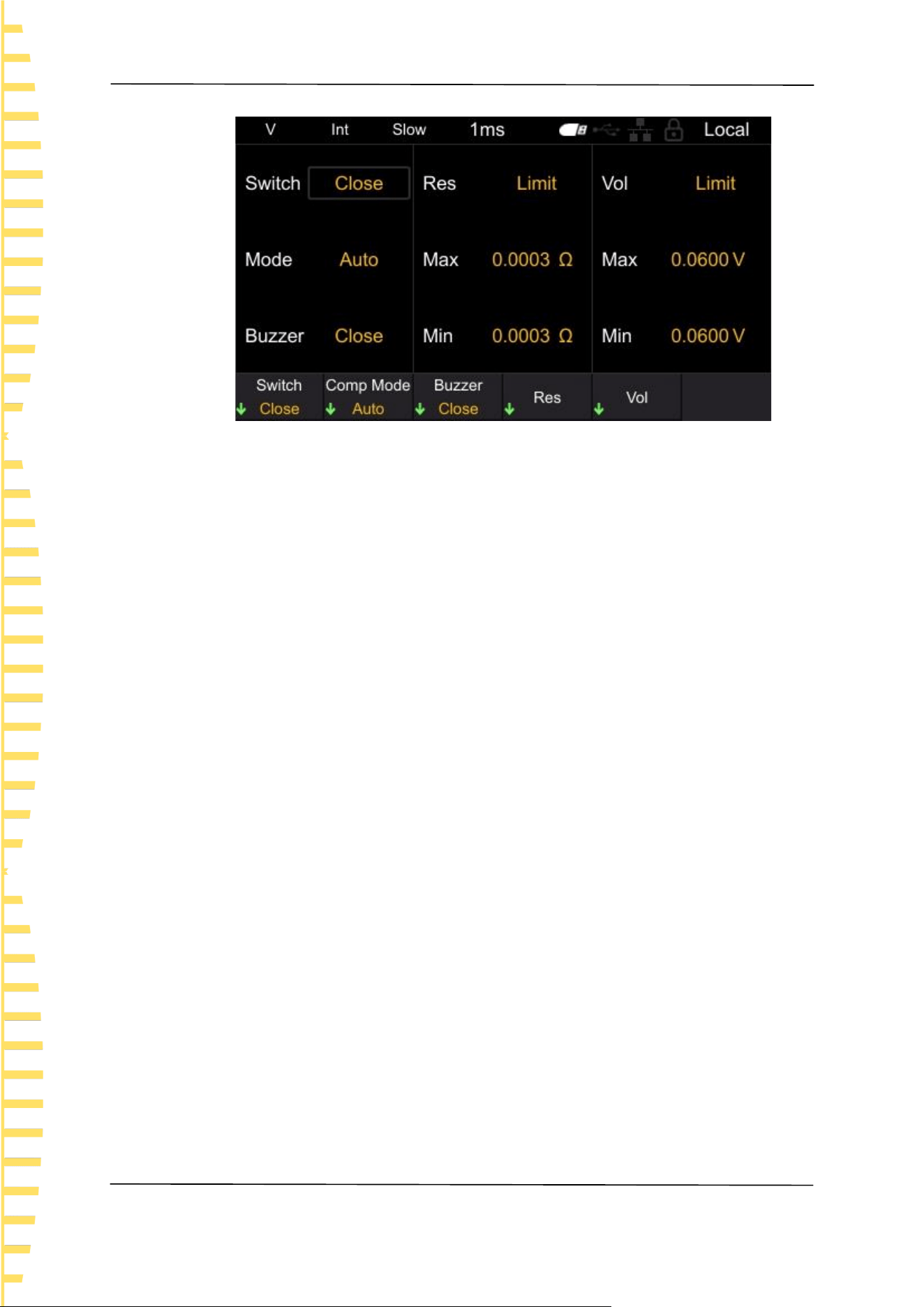
6.2.1 Comparator function settings
Click the [Comp] button to jump to the comparator settings page, as shown in
the figure.
Application measurement
EN
HBT4000 series user manual Copyright © Qingdao Hantek Electronic Co., LTD
30
Figure 6-7 Set comparator function
After entering the comparator interface, there are two methods to modify the
corresponding settings:
Method 1: Use the up/down keys of the arrow keys to move the white box to the
corresponding setting. After confirming the setting to be modified, click the
left/right keys of the arrow keys to modify the corresponding parameters.
Method 2: Click on the menu soft key to set it.
1. Switch
Press the soft key to select whether to turn the comparator function on or off.
2. Comp Mode
Press the soft key to select automatic or manual mode.
3. Buzzer
Press this soft key to set the buzzer to sound. The available types are closed,
HL, IN, BT1, and BT2.
Off: The buzzer is in the off state.
HL: When the comparison result is Hi or Lo, the buzzer emits a "beep..."
sound.
In: When the comparison between voltage and resistance is In, the buzzer
emits a continuous beep sound.
BT1: When the comparison result is In, the buzzer emits a "beep" sound
(continuous sound), and when Hi and Lo, the buzzer emits a "beep..." sound.
BT2: When the state changes from Hi and Lo to In, the buzzer only emits a
"beep" (short sound) once, and when Hi and Lo, the buzzer emits a "beep..."
sound.
4. Res
Press this soft key to set the Limits and Percent of the resistance.
Select the Limits, set the Max(mΩ) and Min(mΩ).
Select the Percent, set the Datum(mΩ) and Percent (%).
5. Vol
Press this soft key to set the Limits and Percent of the voltage.
Application measurement
EN
Copyright © Qingdao Hantek Electronic Co., LTD HBT4000 series user manual
31
Select the Limits, set the Max(V) and Min(V).
Select the Percent, set the Datum(V) and Percent (%).
Note: if there is no command setting in the comparator interface for more
than 30 seconds, the instrument will automatically jump to the measurement
display interface.
After the comparator function is turned on, the comparator interface
parameters cannot be modified.
After the comparator function is turned on, operations that affect
measurement will be prohibited. Prohibited operations include the following:
All settings in the MEA interface are invalid, and clicking the SAVE, LOAD, and
0ADJ buttons is invalid.
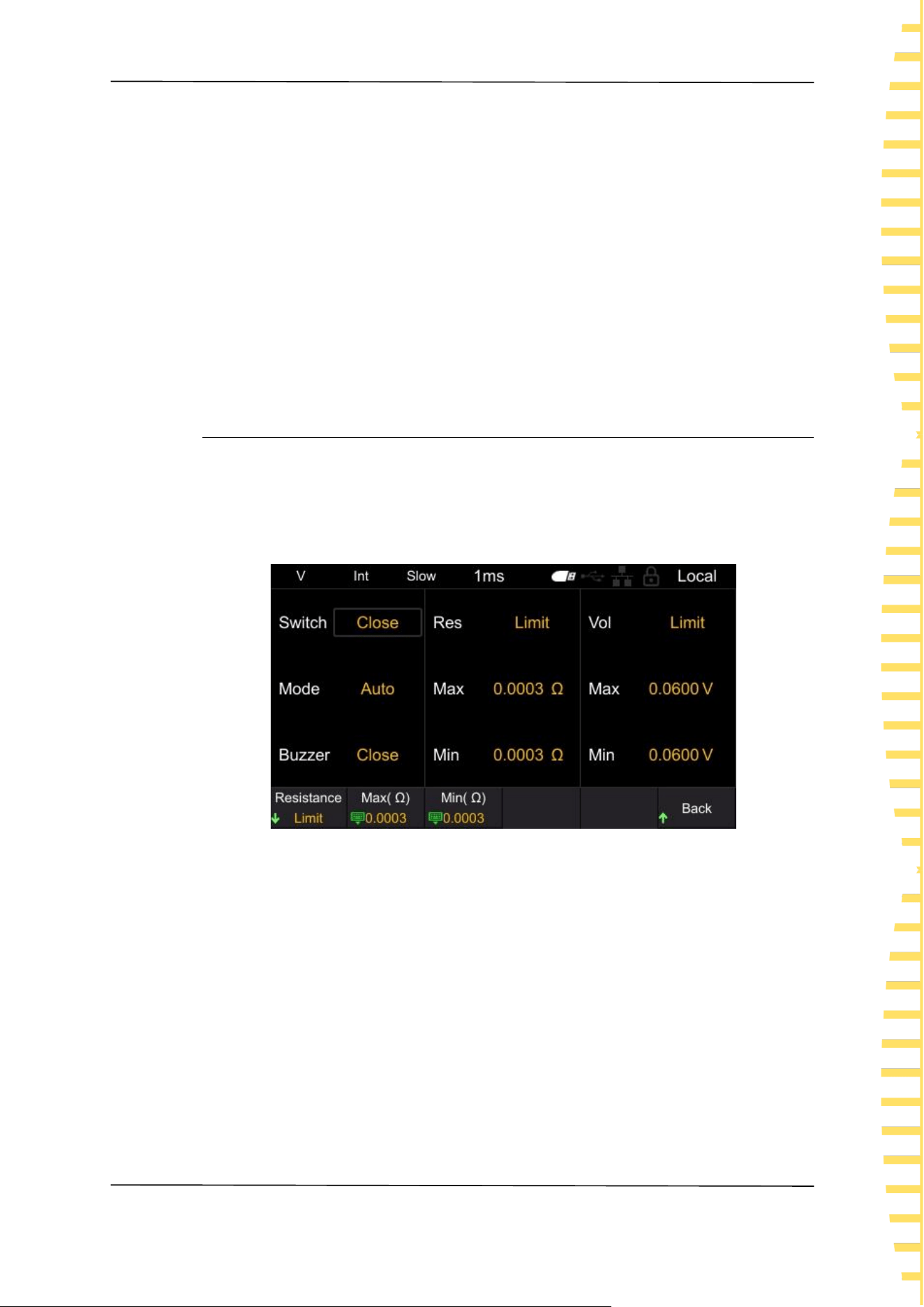
6.2.2 Setting the Limits and Percent
Click on the Res on the comparator page to set the parameters of the resistor
comparator; Click on the Vol on the comparator page to set the voltage
comparator parameters. There are two modes for parameter settings: Limits and
Percent, with the default being the Limits mode.
Figure 6-8 Set the upper and lower limits of resistance
Press this soft key to set the Limits and Percent.
Select the Limits, set the Max and Min.
Select the Percent, set the Datum and Percent.
The steps for setting Max ,Min, Datum, and Percent are the same, using setting
Datum as an example for explanation.
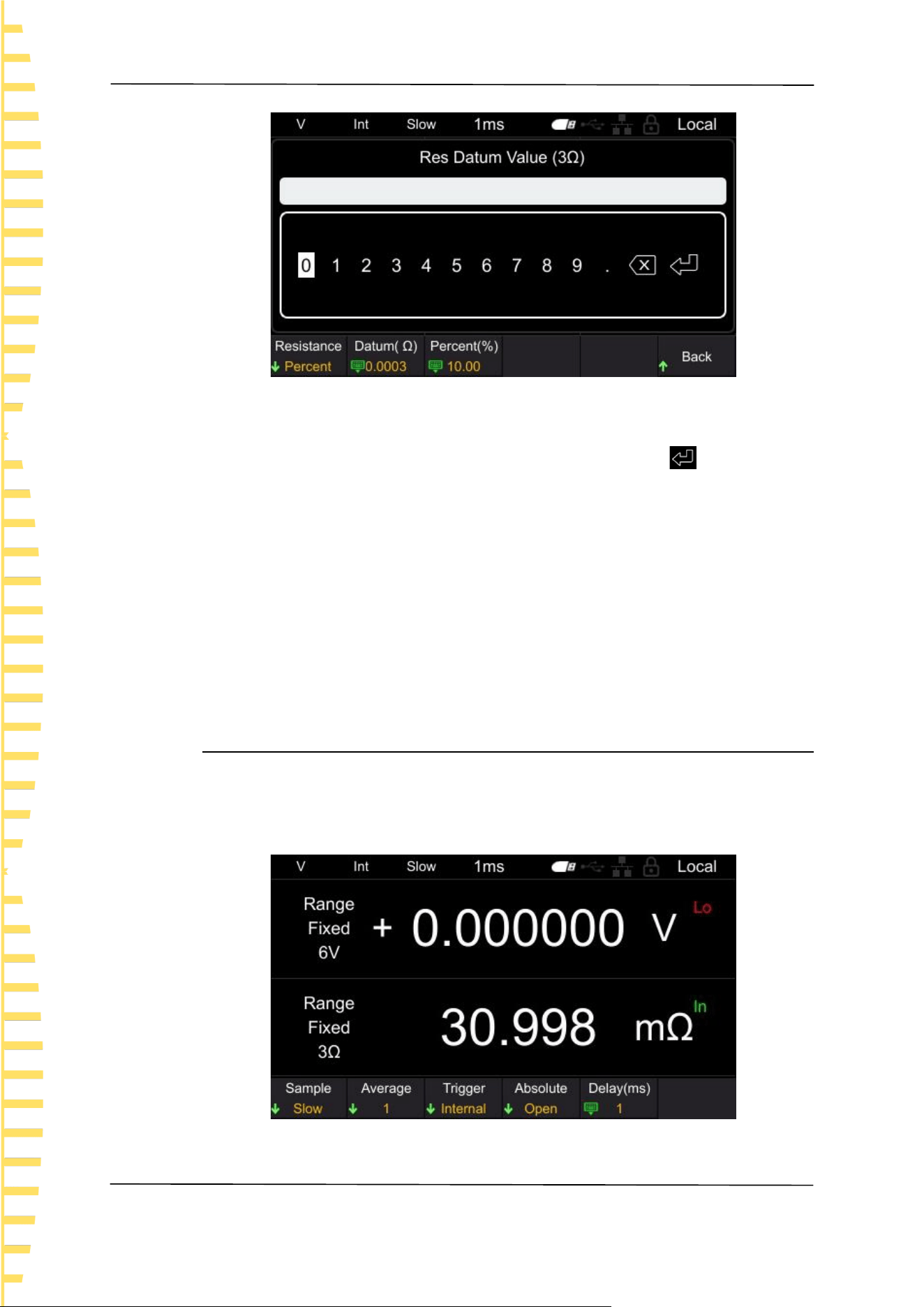
On the resistance ratio interface, click on the Datum (mΩ) and a numeric keypad
will pop up, as shown in the following figure.
Application measurement
EN
HBT4000 series user manual Copyright © Qingdao Hantek Electronic Co., LTD
32
Figure 6-9 Keypad
Move the cursor position by clicking the left and right buttons, and click the
confirm button [OK] to input. Move the cursor to the enter key , then click
[OK] to save and exit.
The parentheses in the keyboard title contain the current measurement gear of
the instrument, as shown in the above figure, which is the 300mΩ gear. The
values set using the keyboard are also in mΩ units. For example, entering 15 on
the keyboard represents the set resistance reference value of 15mΩ.
Note: The comparison value set will change with the switching of the instrument's
measurement gear. For example, if the current gear is 3.9kΩ, set the upper limit
value of the comparator to 3kΩ. When switching to the 300Ω gear, the upper
limit value of the comparator will automatically change to 300Ω.
6.2.3 Page display of comparator
After the comparator is turned on, the instrument will compare it with the
measured value based on the set upper and lower limits or ratio, and display the
comparison results Hi, In, and Lo on the page. As shown in the figure.
Figure 6-10 page display
Application measurement
EN
Copyright © Qingdao Hantek Electronic Co., LTD HBT4000 series user manual
33
Hi: The measured value exceeds the upper and lower limits or proportional range.
In: The measured value is within the upper and lower limits or proportional range.
Lo: The measured value is below the upper and lower limits or proportional range.
6.3 Statistical operation function
Click the [STAT] button to enter the statistical calculation function interface, as
shown in the figure. The following will introduce the statistical function switch,
statistical results, normal distribution map, save/load, data temp, and clear data
functions.
Figure 6-11 Statistical operation function
6.3.1 Switch of statistical function
Click on the [STAT] ->Switch in sequence to set the switch for the statistics
function. Press the corresponding soft key to turn on or off the statistics function.
After turning on the statistics function, the current count will be displayed in real-
time on the screen.
After turning off the statistics function, if data clearing is not performed and the
statistics function is turned on again, the instrument will accumulate on the basis
of the original count.
6.3.2 Statistical Results
The viewing methods for statistical results are divided into [Index] and [List].
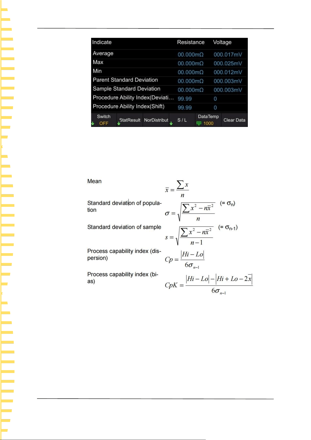
Click on [STAT] ->StatResult ->Index in sequence, and the statistical indicators
will be displayed as follows:
Application measurement
EN
HBT4000 series user manual Copyright © Qingdao Hantek Electronic Co., LTD
34
Figure 6-12 statistical indicators
Calculate and display the Average, Max, Min, Parent Standard Deviation, Sample
Standard Deviation, and Procedure Ability Index for up to 1000 measurement
data. The calculation formula is as follows:
⚫ The n in the formula represents the number of valid data.
⚫ Hi and Lo use the upper and lower limits of the comparator.
⚫ The process capability index refers to the ability to achieve process quality, which
can be understood as the degree of quality deviation and deviation that a process
has.
Generally, the values of Cp and Cpk can be used to evaluate process capability
(as shown below):
Cp, CpK>1.33...... Sufficient process capability
1.33 ≥ Cp, CpK>1.00... Appropriate process capability
1.00 ZCp, CpK, etc. Insufficient process capability
Note:
⚫ When the number of valid data (excluding test anomalies) is 1, the sampling
Application measurement
EN
Copyright © Qingdao Hantek Electronic Co., LTD HBT4000 series user manual
35
standard deviation and process capability index are not displayed.
⚫ When σn-1 is 0, Cp and CpK are 99.99.
⚫ The upper limit of Cp and CpK is 99.99. When Cp and CpK>99.99, it is displayed
as 99.99.
⚫ When CpK is negative, CpK=0.
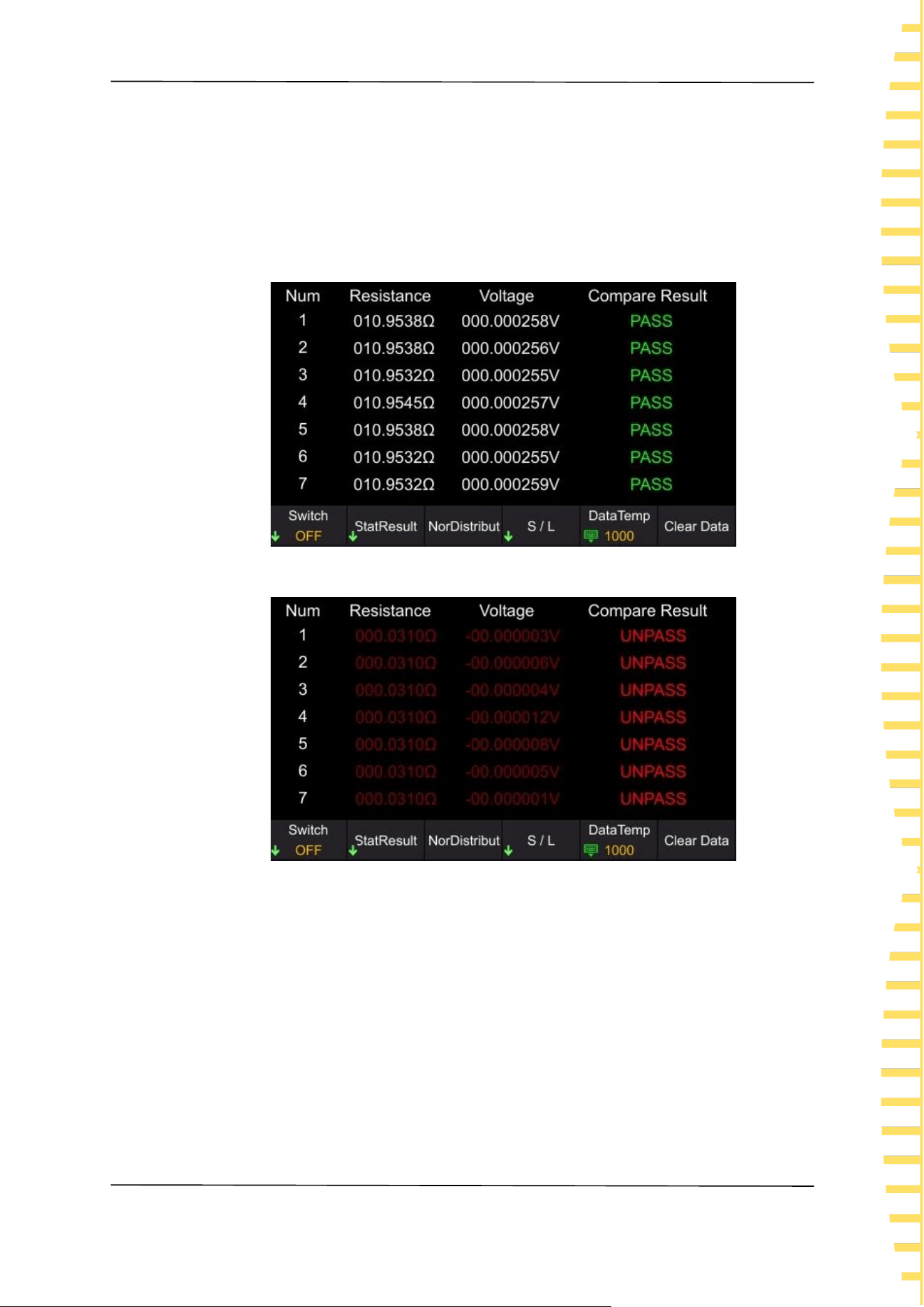
Click on [STAT] ->Statistical Results ->Statistical List, and the statistical list will
be displayed as follows:
Figure 6-13 Statistical List
Figure 6-14 Statistical List
Compare the maximum and minimum values of voltage and resistance set in the
comparator function with the statistical data. If the statistical data is within the
comparison range, the corresponding voltage or resistance will be displayed in
white; If it is not within the comparison range, the corresponding voltage or
resistance will be displayed in red; If the voltage and resistance values are both
within the comparison range, the comparison result shows PASS; On the
contrary, display UNPASS. The judgment results PASS and UNPASS (Hi, In, Lo of
resistance and voltage respectively) can be output to EXT I/O.
Application measurement
EN
HBT4000 series user manual Copyright © Qingdao Hantek Electronic Co., LTD
36
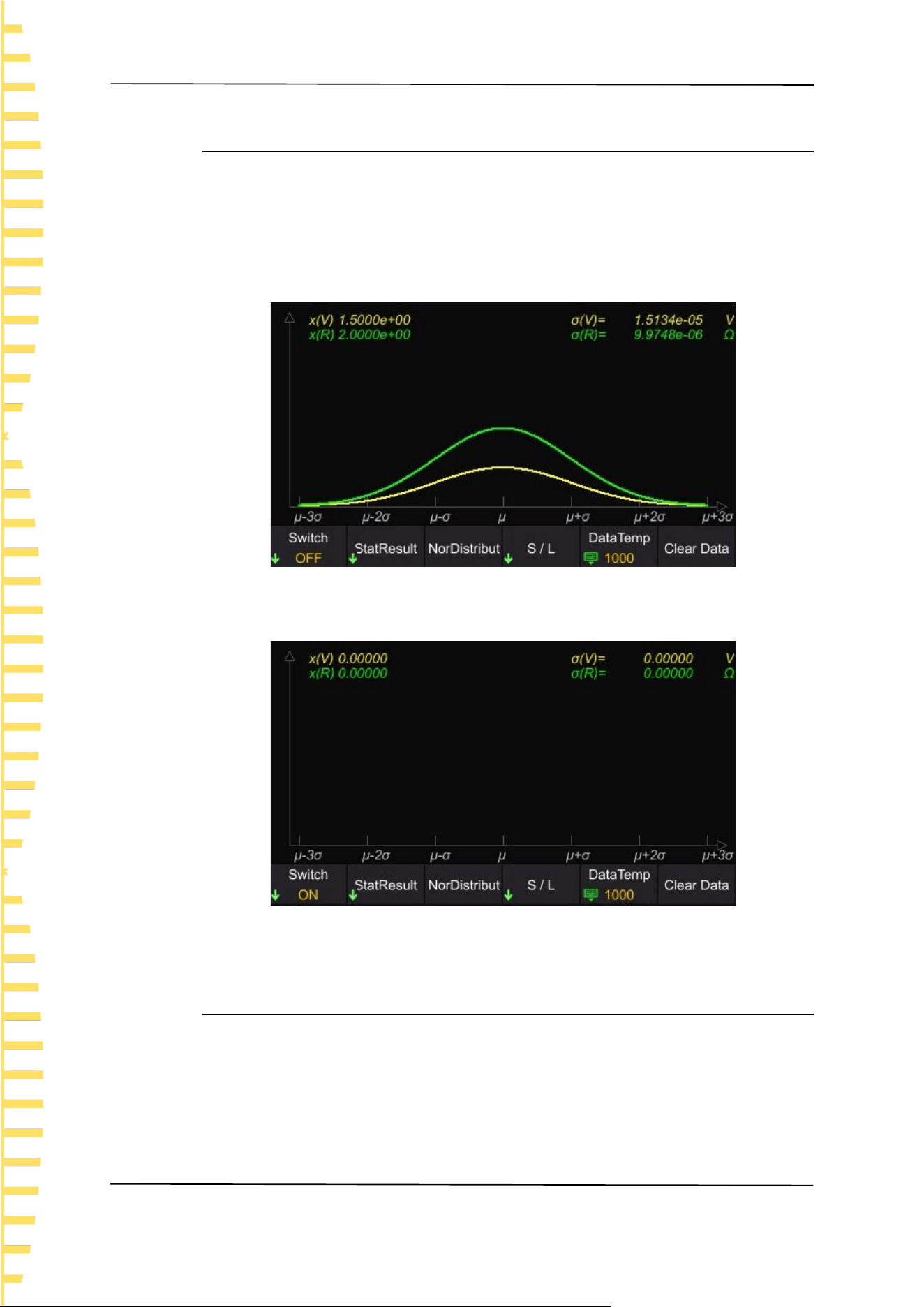
6.3.3 Normal distribution diagram
The HBT4000 series internal resistance tester can generate a normal distribution
map of statistical resistance and voltage measurement data. In the statistics main
interface, click on the Nor Distribut to enter the normal distribution map
interface. X represents the waveform display multiple.
When the instrument has statistical data, it displays as follows:
Figure 6-15 Normal distribution diagram
When there is no statistical data, it is displayed as follows:
Figure 6-16 Normal distribution diagram
6.3.4 SAVE/LOAD
Users can store statistical data in the form of. csv files to external USB drives.
Steps to save data settings:
1 Firstly, turn off the statistics function and insert the USB drive into the USB
port on the front panel of the instrument. After successful connection, the
screen will display "USB Device Connect".

Application measurement
EN
Copyright © Qingdao Hantek Electronic Co., LTD HBT4000 series user manual
37
2 In the statistical calculation interface, click on S/L->Save Data. The screen
will display "File saved successfully", and the instrument will automatically
generate a file name and save it to the USB drive. The file is named based on
the current system time.
Steps for calling up data settings:
1 Firstly, turn off the statistics function and insert the USB drive into the USB
port on the front panel of the instrument. After successful connection, the
screen will display "USB Device Connect ".
2 In the statistical calculation interface, click on S/L->Load Data, use up/down
keys to move the cursor to select a file, click [OK] to retrieve the file, and the
screen will display "File loaded successfully".
3 Click Stat Result -> List to view the file data currently called out.
6.3.5 Data Temp
The HBT4000 series internal resistance tester can record up to 1000 sets of
statistical data. Through the data caching function, the size of the data cache area
can be set, that is, the number of recorded values for each statistical test. For
example, if the data cache is set to 10, the instrument will automatically stop
recording when the recorded value reaches 10.
Click [STAT] ->Data Storage, left and right click to move the cursor position, and
click [OK] for input. Move the cursor to the key , then click [OK] to save and
exit.
6.3.6 Data Clearing
Click [STAT] ->Clear data, click [OK] to confirm clearing, and click [ESC] to cancel
clearing. If the statistics function is not turned off, click Clear Data, and the
instrument will clear the current count and automatically perform the next
statistics.
6.4 System Settings
Click [Utility] to enter the system settings interface. The system settings include
Sys info, Cal, IO, and Other.
Click on [Utility] ->Sys info in sequence to view device information (such as
model, serial number, software version, hardware version, etc.). In addition, system
information can also be viewed by clicking on [VIEW]. After the system
information menu pops up, if no action is taken on the interface for more than 30
seconds, the system information will automatically close.

Application measurement
EN
HBT4000 series user manual Copyright © Qingdao Hantek Electronic Co., LTD
38
Figure 6-17 System settings
6.5 Calibration
Click on [Utility] ->Cal in sequence, enter the password, and you can set [Zero],
[Calib Vol], and [Calib Res].
The specific steps are as follows:
Click Cal to pop up the numeric keypad for the password.
After entering the correct password, enter the calibration submenu; If the
password is incorrect, a prompt message "Password Error" will pop up on the
interface.
Zero
Details reference Appendix C: Performing Zero Adjustment
Voltage calibration setting steps
1 Connect the DC power supply to the input port of the internal resistance
tester and set the power output
2 Input actual voltage
Click on Calib Vol ->Real Vol in sequence, and the page will display Voltage
Calibration (P). Use the left/right keys to move the cursor, click [OK] to enter the
actual voltage value, position the cursor to the key , and then click [OK] to
save the value.

Application measurement
EN
Copyright © Qingdao Hantek Electronic Co., LTD HBT4000 series user manual
39
Figure 6-18 Voltage Calibration
3 Set the next gear
Click Next to correct the next gear. Repeat steps 1 and 2.
When the page displays voltage calibration (N), the red and black probes should
be reversed and calibration should continue. After all gear calibration is
completed, the return menu in the bottom right corner switches to complete.
Click Done to complete the voltage calibration.。
Steps for setting up resistance calibration
1 Connect the four wire resistor to the input port of the internal resistance
tester
2 Input actual resistance value
Click on Calib Res ->Real Res in sequence, and the page will display Resistance
Calibration. Use the left/right keys to move the cursor, click [OK] to enter the
actual resistance value, position the cursor to the key , and then click [OK] to
save the value.
3 Set the next gear
Click Next to correct the next gear. Repeat steps 1 and 2. After all gear
calibration is completed, the return menu in the bottom right corner switches to
complete. Click Done to complete the resistance calibration.
Note:
Before calibration, please preheat the machine for 30 minutes.
Before calibration, please confirm the rated values of the instrument and test
lines, otherwise it may cause damage to the instrument or personal injury
accidents.
6.6 IO
Communication settings include: LAN, Serial, GPIB
Application measurement
EN
HBT4000 series user manual Copyright © Qingdao Hantek Electronic Co., LTD
40
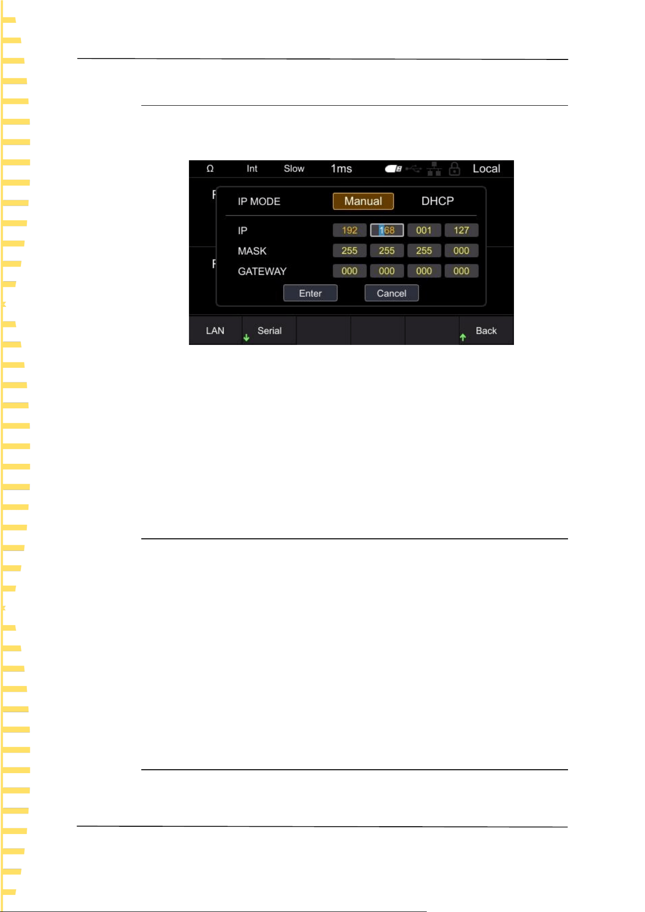
6.6.1 LAN
Click on [Utility] ->IO ->LAN in sequence to enter the LAN settings menu.
LAN parameter settings include: IP mode, IP address, subnet mask, and gateway.
Figure 6-19 LAN parameter settings
Switch input boxes by left/right clicking, click [OK] to select the input box, click
up/down to modify the value, click left/right to move the cursor position, and
click [OK] again to exit the current input box. After setting the LAN parameters,
use the arrow keys to position the cursor to confirm, click [OK] to save and exit.
Note: In the LAN parameter setting interface, if no operation is performed for
more than 30 seconds, the instrument will automatically close the LAN parameter
setting interface.
6.6.2 Serial
Click on [Utility] ->IO ->Serial Port to enter the Serial Port Settings menu.
The serial port parameter settings include Baud, Data, Check, and Stop.
Set the baud rate, click on the corresponding soft key to select the appropriate
baud rate.
Set the data bit and click the corresponding soft key to select the appropriate
data bit.
Set the checksum, which can be selected from no checksum, odd checksum, and
even checksum.
Set the stop position and click the corresponding soft key to select the desired
stop position.
6.6.3 GPIB
Click on [Utility] ->IO ->GPIB in sequence to enter the GPIB settings menu.
Click [OK] to display the position of the cursor. Use up/down to modify values
Application measurement
EN
Copyright © Qingdao Hantek Electronic Co., LTD HBT4000 series user manual
41
and move the cursor position left/right. Click [OK] again to exit the input box, use
the arrow keys to position the cursor to confirm, click [OK] to save and exit.
6.7 Other settings
Other settings include: Sys Time, Brightness, Keytone, Language, and Upgrade.
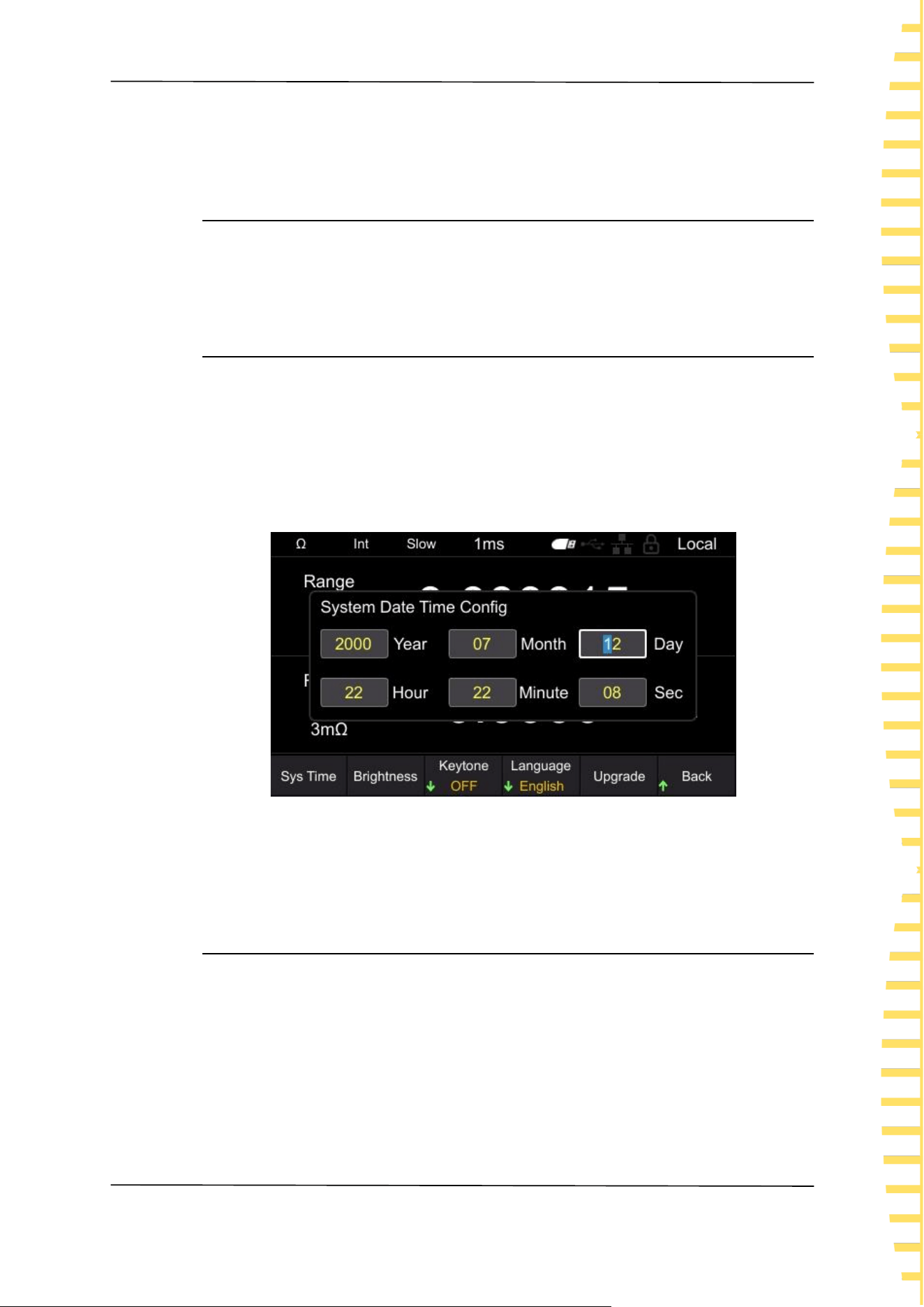
6.7.1 System time
Click on [Utility] ->Other ->Sys Time to enter the clock setting interface.
Switch input boxes by left/right clicking, click [OK] to select the input box, click
up/down to modify the value, click left/right to move the cursor position, click
[OK] again to save and exit the current input box. Click [ESC] to exit the system
time setting. The system time is mainly used for naming instruments when saving
files and screenshots.
Figure 6-20 Set system time
Note: If no action is taken after 30 seconds in the system time setting interface,
the instrument will automatically close the system time setting interface.
6.7.2 Brightness
Click on [Utility] ->Other -> Brightness to enter the screen brightness setting
interface. Click the left/right button to decrease or increase screen brightness in
steps of 5. The adjustable range is 10-100. The default value is 50.

Application measurement
EN
HBT4000 series user manual Copyright © Qingdao Hantek Electronic Co., LTD
42
6.7.3 Keytone
Click on [Utility] ->Other ->Keytone to turn on or off button sounds.
6.7.4 Language
Click on [Utility] ->Other ->Language, and switch to Chinese or English.
6.7.5 Upgrade
Copy the firmware to a USB drive and insert it into the USB port on the front
panel of the instrument. Click on [Utility] ->Other ->Upgrade in sequence, and
the screen will pop up "Do you want to upgrade the system?". Move the cursor
to confirm and click [OK] to complete the upgrade settings. When the progress
bar reaches 100%, the instrument will automatically restart, and the application
upgrade is completed.
6.8 SAVE
The storage function can store the configuration used by the instrument for the
next power on to the internal memory or USB drive of the machine. Click the
[SAVE] button to pop up the storage function menu, which includes [Save Path],
[Inter/Exter Save], and [Boot Set] options. When the storage function is enabled,
the storage settings cannot be modified.
Note: The configuration saved here is the one used for the next power on of the
instrument, that is, the startup settings.
6.8.1 Save Path
The save path is divided into [Inter] and [Exter]. The default path is [Inter], which
can be set to [Exter] when connecting to USB.
Click on [SAVE] ->Save Path in sequence, and when selecting Internal, the
instrument will save the configuration used for the next power on to the
machine's internal system; When selecting an external device, the instrument
saves the configuration used for the next power on to the USB drive.

Application measurement
EN
Copyright © Qingdao Hantek Electronic Co., LTD HBT4000 series user manual
43
6.8.2 Inter/Exter Save
When the save path is selected internally, the menu bar displays Inter Save; When
selecting an external save path, the menu bar displays Exter Save.
Internal save setting steps: After setting the required storage options, click on
Inter Save. In the pop-up menu, there are a total of 6 states from 0 to 5 to choose
from. Click the corresponding soft key to save to the corresponding status
location. If you want to save the startup settings to 0 state, you need to click the 0
soft key, and the screen will pop up "Save Stat0. bin successful!", indicating that
the settings are successful. If the entered state already exists, clicking the
corresponding soft key will overwrite the original state configuration.
External save setting steps: After setting the required storage options, click on
Exter Save, and the instrument will automatically generate a file name and save
the status to the USB drive.
6.8.3 Boot Set
The startup settings include: default, previous, 0, 1, 2, 3, 4, and 5. The instrument
is set to default by default.
⚫ Default: The signal generator automatically calls up the default settings when
turned on.
⚫ Last Off: The internal resistance tester automatically saved the settings before
shutdown, and after restarting, the internal resistance tester will automatically
call up the settings before the previous shutdown. Including all system
parameters, except for clock sources.
⚫ 0, 1, 2, 3, 4, and 5: refer to the boot configuration stored inside the machine.
Press the [SAVE] ->Boot Set soft key and select the desired configuration type.
6.9 Load
The loading function can load the configuration used when the instrument is
powered on from internal memory or USB drive. Click the [LOAD] button to pop
up a loading function menu, which includes storage functions such as [Load Path],
[Inter/Exter Load], and [Boot Set] options.
Note: The configuration loaded here is the one used when the instrument is
powered on, that is, the startup settings.
6.9.1 Load Path
The loading path is divided into [Interl] and [Exter].

Application measurement
EN
HBT4000 series user manual Copyright © Qingdao Hantek Electronic Co., LTD
44
Click [LOAD] ->Load Path in sequence, and click the corresponding soft key to
select internal or external.
6.9.2 Inter/Exter Save
When selecting internal loading path, the menu bar displays Intern; When the
loading path is selected as external, the menu bar displays Extern.
Internal loading setting steps: Set the loading path to internal, click on Inter Load,
and in the pop-up menu, there are a total of 6 states to choose from, ranging
from 0 to 5. Click the corresponding soft key to load it into the corresponding
startup settings. If there are saved startup settings in the current state, the screen
will display "StatX.bin Load Success!"; If there are no saved startup settings in the
current state, the screen will display "Load Failed StatX.bin Does Not Exist!".
External loading setting steps: Insert the USB flash drive into the USB HOST
interface on the front panel, set the loading path to external, click on Exter Load,
use up/down keys to select the. csv file, and click [OK] to load the file.
6.9.3 Boot Set
The startup settings include: Default, Last Off, 0, 1, 2, 3, 4, and 5. The default
selection for the instrument is default.
Press the [LOAD] ->Boot Set soft key, select the desired configuration type, and
complete the power on settings.
6.10 0 ADJ
To eliminate errors caused by the bias voltage of the instrument itself or the
measurement environment, perform zero adjustment before measurement.
Before conducting the test, the instrument needs to be zeroed first. Before
zeroing, short-circuit the test line using the correct method, and then press the
[0ADJ] button to perform zeroing. The interface will display "Zero adjustment
Failed/Success" and disappear after 2 seconds.
Note:
⚫ Perform zero adjustment on all ranges.
⚫ Even if the power is cut off, the compensation value after zero adjustment will
continue to be maintained.
⚫ Zero adjustment can be performed on the 0ADJ terminal of EXTI/O.
⚫ After successful zeroing, continue zeroing. If zeroing fails, retain the previous
zeroing result.

Application measurement
EN
Copyright © Qingdao Hantek Electronic Co., LTD HBT4000 series user manual
45
6.11 Local key
Click [Local], the lock screen icon on the screen will light up, and clicking any
button other than this button is an invalid operation. Click the button again, and
the lock screen icon on the screen will turn gray.
In remote control mode, click [Local] to switch remote control to local control.
6.12 TRIG key
When manually triggered, press this button to trigger one measurement at a time.
6.13 Plus/Minus keys
Quickly adjust the voltage and resistance range. By default, the resistance range is
adjusted and displayed as Ω in the upper left corner of the screen. Press [Range]
to switch to adjusting the voltage range, and switch the range shortcut label to V.
Note: Using the plus/minus keys to adjust the range, it is not possible to adjust
the range to automatic.
6.14 Range key
Press [Range] to set the range of voltage and resistance.
6.15 ESC key
Use the [ESC] button to return or cancel the current operation. The functions of
the [ESC] button include canceling input/canceling pop-up boxes/canceling
submenus.
6.16 P key
Used to restore the instrument status to the factory default values.
Function
Default value
Range

Application measurement
EN
HBT4000 series user manual Copyright © Qingdao Hantek Electronic Co., LTD
46
Function
Default value
Measurement type
V&R
Voltage range
Auto
Resistance range
Auto
MEA
Sample
Slow
Average
1
Trigger
Internal
Absolute
Open
Delay(ms)
1
SAVE/LOAD
Boot Set
Default
STAT
Switch
OFF
Data Temp
1000
COMP
Switch
Close
Comp Mode
Auto
Buzzer
Close
Resistance
Limit
Voltage
Limit

Application measurement
EN
Copyright © Qingdao Hantek Electronic Co., LTD HBT4000 series user manual
47
Function
Default value
Utility
Brightness
50%
GPIB Address
2
Key tone
OFF
Language
Chinese
IP
192.168.1.127
MASK
255.255.255.0
IP MODE
Manual
Serial-Baud
9600
Serial-Data
7
Serial-Check
None
Serial-Stop
1
Table 6-1 Factory Default
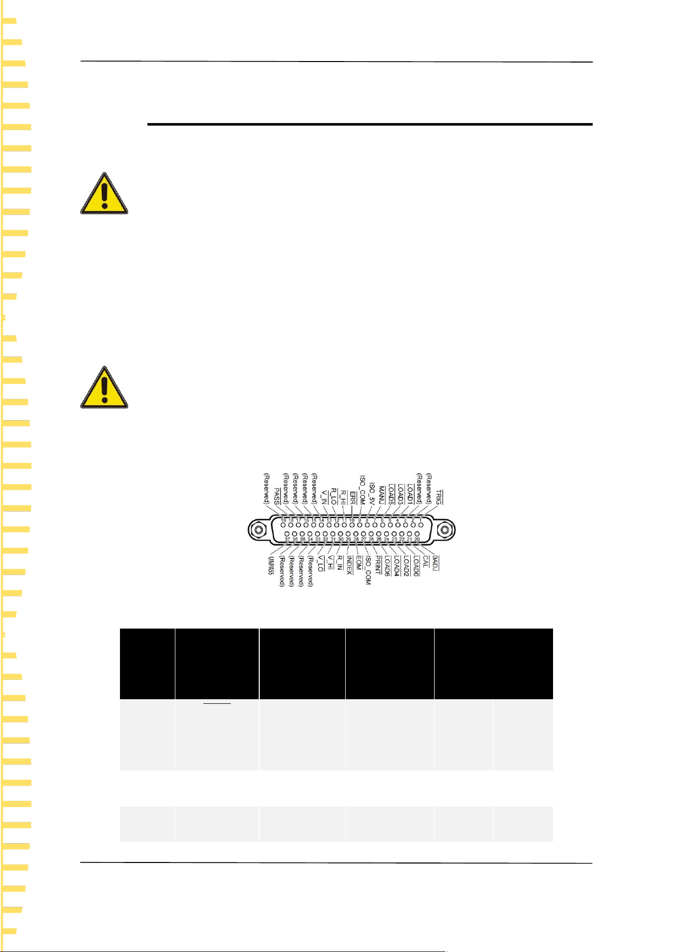
EXT I/O
EN
HBT4000 series user manual Copyright © Qingdao Hantek Electronic Co., LTD
48
7 EXT I/O
The EXTI/O interface provides external output and external control functions.
Please read the precautions before connecting.
Warning:
To prevent electric shock accidents and instrument malfunctions, please follow the
following instructions when connecting the wiring of the EXTI/O connector.
⚫ Please cut off the power supply of this instrument and connect it before
connecting it.
⚫ If the wiring detaches during operation, it may come into contact with other
conductive components, which is very dangerous.
⚫ Please securely secure the external connector with screws.
⚫ Please insulate the instruments and devices connected to the EXTI/O
connector appropriately.
Note:
⚫ Do not input voltage or current above the rated value to the EXTI/O
connector.
⚫ When using a relay, be sure to install a freewheeling diode.
⚫ Do not use ISO_ 5V and ISO_ COM forms a short circuit.
Figure 7-1 EXT I/O connector
Needle
number
Signal
name
I/O
Function
Logic
1
𝑻𝑹𝑰𝑮
IN
external
trigger
negative
edge
2
(Reserved)
IN
-
-
-
3
(Reserved)
IN
-
-
-

EXT I/O
EN
Copyright © Qingdao Hantek Electronic Co., LTD HBT4000 series user manual
49
Needle
number
Signal
name
I/O
Function
Logic
4
𝑳𝑶𝑨𝑫𝟏
IN
Read Number
Bit1
negative
edge
5
𝑳𝑶𝑨𝑫𝟑
IN
Read Number
Bit3
negative
edge
6
𝑳𝑶𝑨𝑫𝟓
IN
Read Number
Bit5
negative
edge
7
𝑴𝑨𝑵𝑼
IN
Manual
control of
comparator
negative
edge
8
ISO_5V
-
Insulated
power supply
5V output
-
-
9
ISO_COM
-
Insulated
power supply
common
terminal
-
-
10
𝑬𝑹𝑹
OUT
Test exception
negative
edge
11
𝑹_𝑯𝑰
OUT
Resistance
determination
negative
edge

EXT I/O
EN
HBT4000 series user manual Copyright © Qingdao Hantek Electronic Co., LTD
50
Needle
number
Signal
name
I/O
Function
Logic
result HI
12
𝑹_𝑳𝑶
OUT
Resistance
determination
result Lo
negative
level
13
𝑽_𝑰𝑵
OUT
Resistance
determination
result IN
negative
level
14
(Reserved)
OUT
-
-
-
15
(Reserved)
OUT
-
-
-
16
(Reserved)
OUT
-
-
-
17
(Reserved)
OUT
-
-
-
18
𝑷𝑨𝑺𝑺
OUT
Judgment
result PASS
negative
level
19
(Reserved)
OUT
-
-
-
20
𝟎𝑨𝑫𝑱
IN
Zero
negative
edge
21
𝑪𝑨𝑳
IN
Perform self
calibration
negative
edge
22
𝑳𝑶𝑨𝑫𝟎
IN
Read the
Number Bit0
negative
level

EXT I/O
EN
Copyright © Qingdao Hantek Electronic Co., LTD HBT4000 series user manual
51
Needle
number
Signal
name
I/O
Function
Logic
23
𝑳𝑶𝑨𝑫𝟐
IN
Read the
number Bit2
negative
level
24
𝑳𝑶𝑨𝑫𝟒
IN
Read the
number Bit4
negative
level
25
𝑳𝑶𝑨𝑫𝟔
IN
Read the
number Bit6
negative
level
26
𝑷𝑹𝑰𝑵𝑻
IN
Measurement
value printing
negative
edge
27
ISO_COM
-
Insulated
power supply
common
terminal
-
-
28
𝑬𝑶𝑴
OUT
End Of
Measurement
negative
edge
29
𝑰𝑵𝑫𝑬𝑿
OUT
Measurement
reference
signal
negative
level
30
𝑹_𝑰𝑵
OUT
Resistance
determination
negative
level

EXT I/O
EN
HBT4000 series user manual Copyright © Qingdao Hantek Electronic Co., LTD
52
Table 7-1 EXT I/O output terminal
Note:The outer shell of the connector is connected to the metal part of the
instrument, and also connected (conductive) to the protective grounding terminal
of the power socket.
7.1 Input terminal function
⚫ 𝑻𝑹𝑰𝑮
External trigger input, when the trigger source is set to external, it will change
Needle
number
Signal
name
I/O
Function
Logic
result IN
31
𝑽_𝑯𝑰
OUT
Voltage
judgment
result Hi
negative
level
32
𝑽_𝑳𝑶
OUT
Voltage
judgment
result Lo
negative
level
33
(Reserved)
OUT
-
-
-
34
(Reserved)
OUT
-
-
-
35
(Reserved)
OUT
-
-
-
36
(Reserved)
OUT
-
-
-
37
𝑼𝑵𝑷𝑨𝑺𝑺
OUT
Judgment
result
UNPASS
negative
level

EXT I/O
EN
Copyright © Qingdao Hantek Electronic Co., LTD HBT4000 series user manual
53
from a high-level signal to a low-level signal and trigger a measurement at the
edge of the jump. When triggered internally, trigger measurement cannot be
performed.
⚫ 𝑳𝑶𝑨𝑫𝟎~𝑳𝑶𝑨𝑫𝟔
The panel display number used for external input selection calls. When the
number is selected, a signal is input, and the device reads the configuration
corresponding to the selected panel display number for measurement. If the
number value does not change when input, perform a measurement when
triggered externally.
⚫ 𝟎𝑨𝑫𝑱
External input control zeroing function, when the signal changes from high level
to low level, it triggers the application program to perform a zeroing function in
the form of an interrupt.
⚫ 𝑷𝑹𝑰𝑵𝑻
External input control screenshot function, when the signal changes from high
level to low level, it triggers the application program to execute a screenshot
function in the form of an interrupt.
⚫ 𝑪𝑨𝑳
External input control correction function, when the signal changes from a high
level to a low level signal, it triggers the application program to perform a
correction function in the form of an interrupt.
⚫ 𝑴𝑨𝑵𝑼
External input control comparator function, default to high level. When the level
changes (such as high to low or low to high), it triggers the application program
to read the current level status in the form of an interrupt. If an interrupt is
generated and the level is low, the comparator function is turned on. If it is high,
the comparator function is turned off.
7.2 Output terminal function
⚫ 𝑬𝑶𝑴
The measurement end signal is divided into HOLD mode and PULSE mode. In the
external trigger mode, after the measurement is completed, the HOLD mode
keeps the EOM at a low level and continues until the next measurement begins
(when the external trigger is generated) to recover to a high level. The PULSE
mode outputs a configurable width of low-level pulses and then returns to a high
level state; In the internal triggering mode, after the measurement is completed,
the HOLD mode outputs a fixed width of low-level pulses according to the
measurement mode and restores the high-level state, while the PULSE mode
outputs a configurable width of low-level pulses and restores the high-level state.
⚫ 𝑰𝑵𝑫𝑬𝑿
The measurement process indicator signal outputs an INDEX signal at a low level

EXT I/O
EN
HBT4000 series user manual Copyright © Qingdao Hantek Electronic Co., LTD
54
when waiting for triggering, delay, self correction, and operation states. The
output signal is at a high level when in range configuration, data acquisition, data
transmission, and operation states. The signal can be removed from the test
object from high to low.
⚫ 𝑬𝑹𝑹
The measurement of abnormal output signals can be divided into two modes:
synchronous output and asynchronous output. In synchronous output mode, the
ERR state is synchronized with the EOM output, and it is determined that the ERR
state is valid when the EOM output is low. In asynchronous output mode, the ERR
state is updated in real-time and has no synchronous timing relationship with the
EOM.
⚫ 𝑹_𝑯𝑰
、
𝑹_𝑰𝑵
、
𝑹_𝑳𝑶
、
𝑽_𝑯𝑰
、
𝑽_𝑰𝑵
、
𝑽_𝑳𝑶
、
𝑷𝑨𝑺𝑺
、
𝑼𝑵𝑷𝑨𝑺𝑺
The output results of the comparator function, R-HI, R-IN, R-LO, V-HI, V-IN, V-LO
represent the comparison results of resistance and voltage, respectively. The PASS
signal is judged under different conditions based on different measurement
modes. In the resistance voltage mode, when the resistance comparison result is
R-IN and the voltage is V-IN, the PASS is at a low level; In resistance mode, when
the comparison result is R-IN, PASS is at a low level; In voltage mode, when the
comparison result is V-IN, PASS is at a low level. The UNPASS signal is a logic
inversion output of the PASS signal.
Note:
⚫ When the measurement conditions of this instrument change, I/O signals
cannot be used.
⚫ When the power is turned on, the signal and signal are initialized to HIGH
(OFF).
⚫ When there is no need to switch measurement conditions, please fix all
𝑳𝑶𝑨𝑫𝟎~𝑳𝑶𝑨𝑫𝟔 as Hi or Lo.
⚫ To avoid erroneous judgments, please confirm the comparator's judgment
through both 𝑷𝑨𝑺𝑺 and 𝑼𝑵𝑷𝑨𝑺𝑺 signals.

Analog Output
EN
Copyright © Qingdao Hantek Electronic Co., LTD HBT4000 series user manual
55
8 Analog Output
The analog output of resistance measurement values is recorded by connecting
the analog output to a recorder to record the changes in resistance values.
⚫ To avoid electric shock and instrument malfunction, please set the power
supply of this instrument and the connected instrument to OFF when
connecting the analog output terminal.
⚫ To avoid damaging this instrument, please do not short circuit the output
terminals or input voltage.
8.1 Connect analog output
Analog output specifications
Output voltage
DC 0V~DC 3.1V(f.s.)
Resolution ratio
12 bit resolution (approximately 1mV)
output resistance
100Ω
Output items
Resistance measurement value
(display count value) OF, fixed at 3.1V
when testing abnormal, fixed at 0V
when negative value
Output rate
0 count value~31000 count values
0V~3.1V
Output accuracy
Resistance testing accuracy is 0.2% f. s.
(temperature coefficient is 0.02% f.
s./℃)
Response time
Resistance measurement response
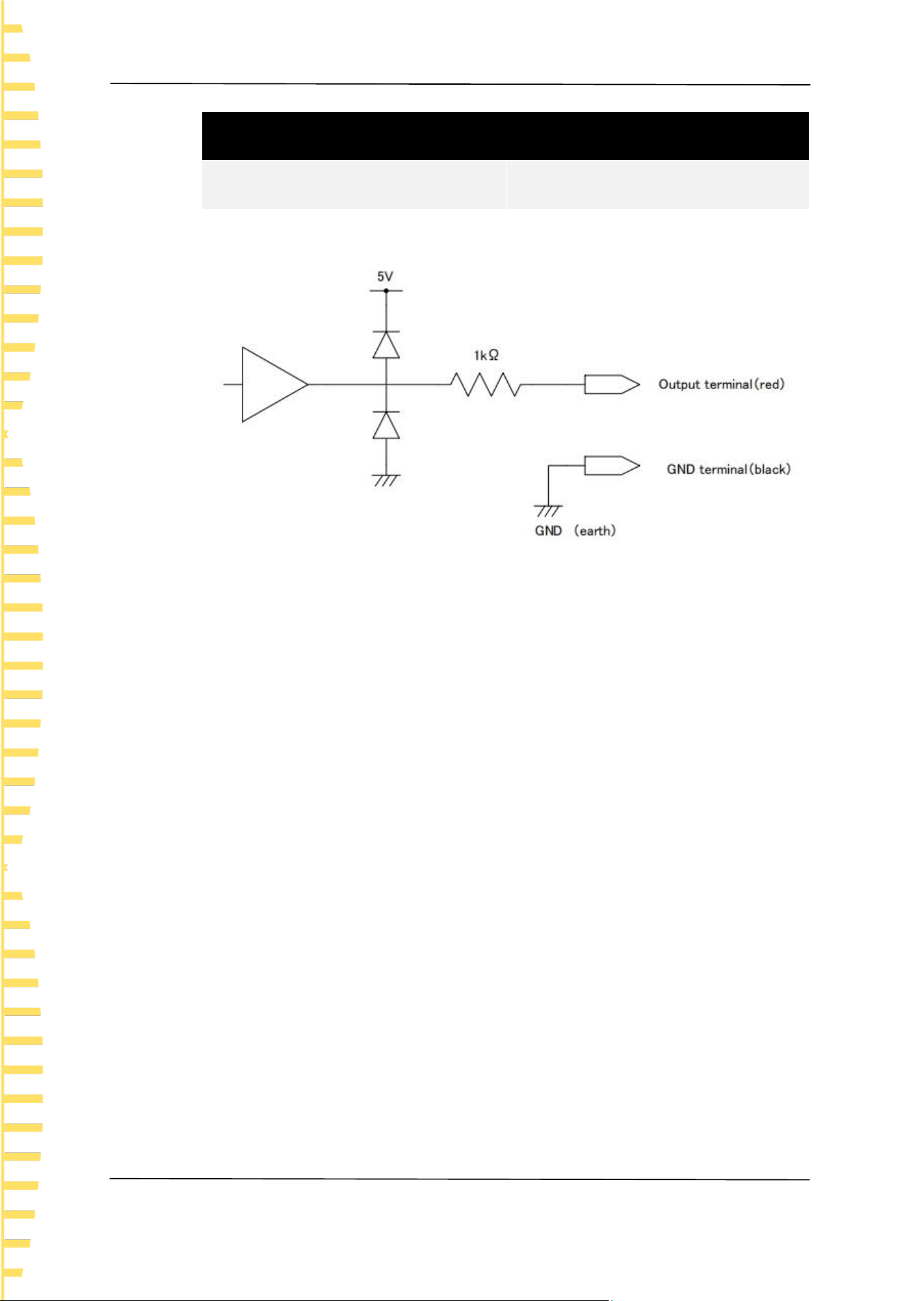
Analog Output
EN
HBT4000 series user manual Copyright © Qingdao Hantek Electronic Co., LTD
56
Analog output specifications
time+sampling time+1 ms
Table 8-1 Analog output specifications
Figure 8-1Connection diagram
Note:
⚫ The output impedance is 100 Ω. Please use a connecting instrument with an
input impedance of 5M Ω or higher.
⚫ If cables are connected, external noise may be picked up. Please use bandpass
filters, etc. on the connected instruments as needed. Connect the GND
terminal of the analog output to the ground wire (metal part of the casing).
⚫ The output voltage is updated based on the sampling timing of resistance
measurement.
⚫ The recorded waveform is in a stepped shape. (Because the response of the
output circuit is very fast compared to the update cycle)
⚫ In automatic range, due to range switching, even if the resistance value is the
same, the output voltage is 1/10 (or 10 times). It is recommended to use in
manual range.
⚫ When changing settings (range switching, etc.) and when the power is turned
off, the output is set to 0 V.
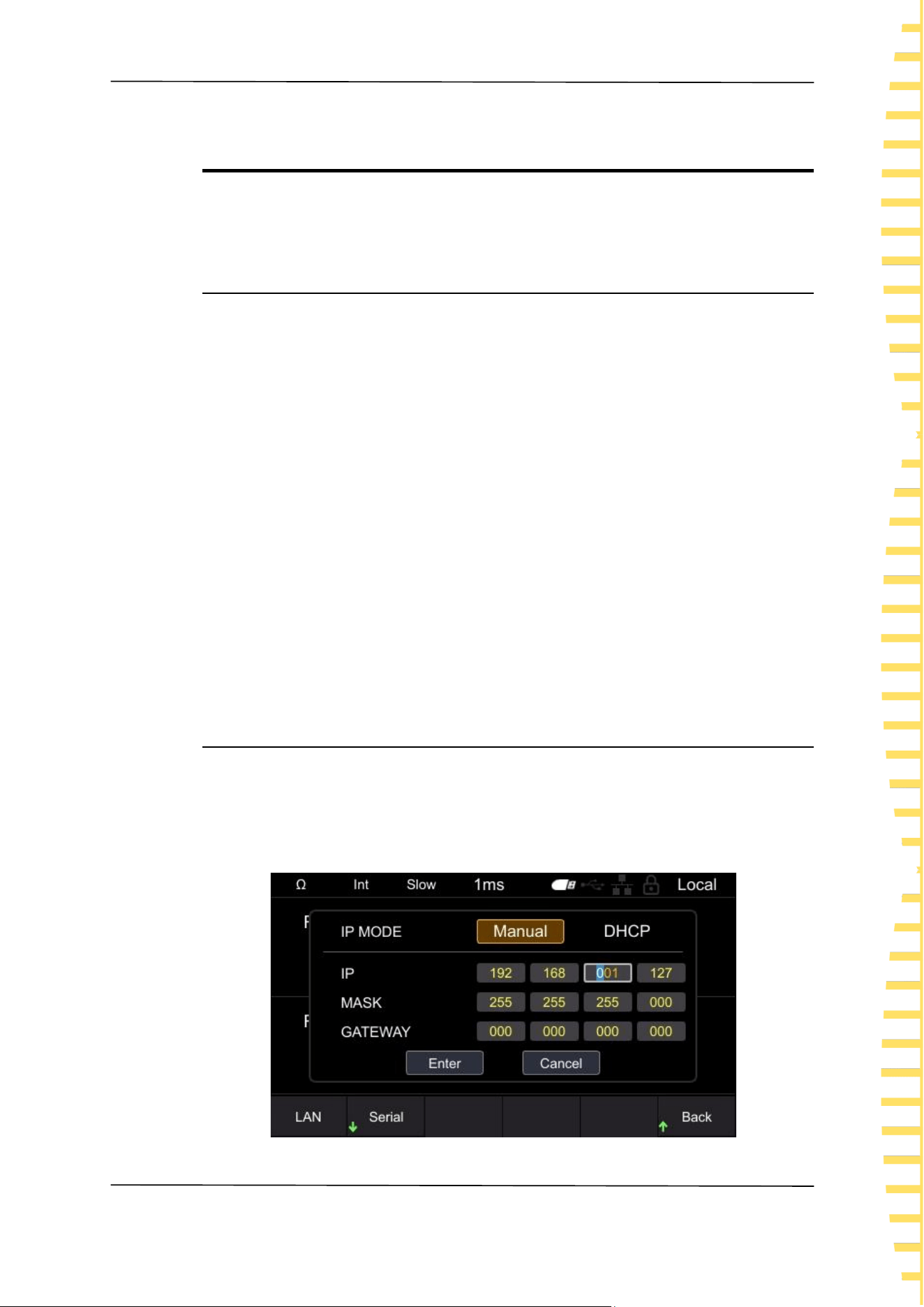
Remote control
EN
Copyright © Qingdao Hantek Electronic Co., LTD HBT4000 series user manual
57
9 Remote control
When remote control is enabled, the Local displayed in the upper right corner of
the interface switches to Remote.
9.1 USB remote control
Use a USB cable to connect the computer's USB port to the USB interface on the
back panel of the internal resistance tester. At this point, the upper right corner of
the measurement display interface of the internal resistance tester displays the
USB connected label.
Download and install IO software from the following address:
https://www.keysight.com/main/software.jspx?ckey=2175637&lc=chi&cc=CN&ni
d=-11143.0.00&i d=2175637
Open the IO software, locate the device, send a command to check if
communication is normal, and after obtaining normal communication, use the
SCPI command to remotely control the internal resistance tester.
For example:
Query :FETC? (Read the latest measurement values)
Response 288.02E-3 , 1.3921E+0 (ΩV function)
The measured resistance value is 288.02m Ω, and the measured voltage value is
1.3921V
9.2 LAN remote control
Connect the backend network port of the computer to the rear panel network
port of the internal resistance tester using a LAN cable.
Click on [Utility] ->IO ->LAN in order to set the LAN parameters of the internal
resistance tester.
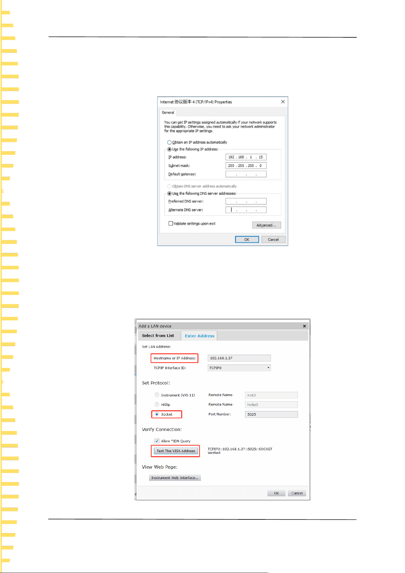
Remote control
EN
HBT4000 series user manual Copyright © Qingdao Hantek Electronic Co., LTD
58
Figure 9-1 Set LAN parameters
Manually configure the IP and other information of the computer, and set the
Ethernet properties of the computer:
Figure 9-2 Set computer Ethernet properties
After opening the IO software and successfully connecting, the device will appear
in the LAN list. If the device does not appear, you can manually add the device,
enter the IP address and protocol of the device, test the VISA address, and click
OK to add a new device.
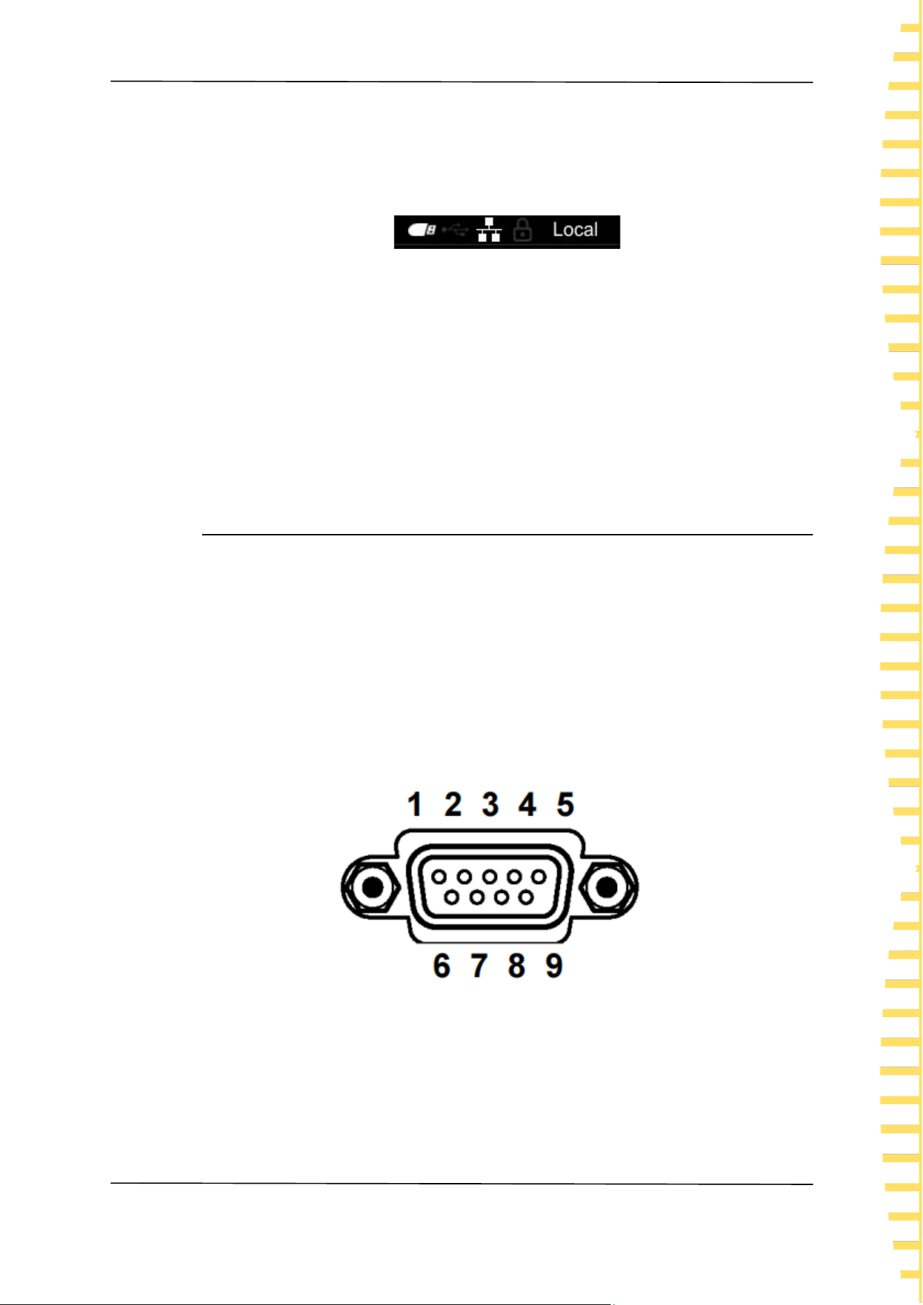
Remote control
EN
Copyright © Qingdao Hantek Electronic Co., LTD HBT4000 series user manual
59
Figure 9-3 Manually adding devices
After successful connection, the network port icon in the upper right corner of the
machine measurement display interface is displayed as follows:
Figure 9-4 Network interface icon display
Like USB remote control, after obtaining normal communication, SCPI instructions
can be used to control the power output.
If there is a DHCP server in the local area network, the DHCP function can be
turned on, and the instrument will automatically obtain IP and other information
from the DHCP server without the need for manual settings.
Note: There is no DHCP server in the local area network, and IP and other
information must be manually configured.
9.3 Serial port control
Click on [Utility] ->IO ->Serial, and set the serial port parameters of the internal
resistance tester.
Click on the Baud, and the available baud rates are 9600, 19200, 38400, 57600,
115200, and 230400.
Click on the Data, there are 7 and 8 data bits to choose from.
Click on the Check to select no checksum, odd checksum, and even checksum.
Click on the Stop, and there are 1 and 2 stop bits to choose from.
Use an RS232/485 cable to connect the computer's RS232/485 port to the
RS232/485 interface on the rear panel of the internal resistance tester.
Figure 9-5 RS232/485 connector

Remote control
EN
HBT4000 series user manual Copyright © Qingdao Hantek Electronic Co., LTD
60
Needle
number
Signal name
Signal
Notes
customary
EIA
JIS
1
DCD
CF
CD
Not used
Not
connected
2
RxD
BB
RD
Receive
data
3
TxD
BA
SD
Send data
4
DTR
CD
ER
Data
terminal
ready
Connected
to
internal+5V
5
GND
AB
SG
Signal
grounding
6
DSR
CC
DR
Not used
Not
connected
7
RTS
CA
RS
Send
request
Connected
to
internal+5V
8
CTS
CB
CS
Not used
Not
connected
9
RI
CE
CI
Not used
Not
connected
Table 9-1 RS232/485 connector pin number
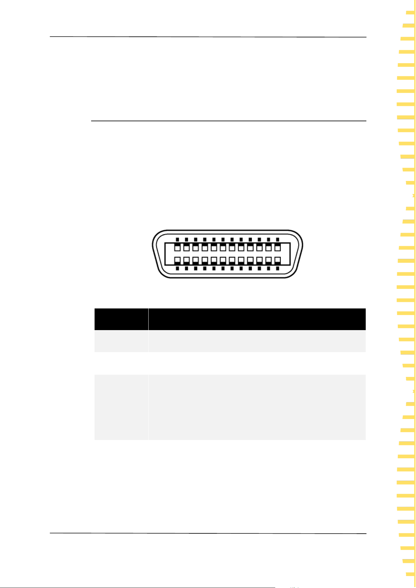
Remote control
EN
Copyright © Qingdao Hantek Electronic Co., LTD HBT4000 series user manual
61
Open the IO software, select Add Device, set the corresponding baud rate, data
bits, checksum, and stop bits, test the VISA address, and click OK to add a new
device. Like USB remote control, after obtaining normal communication, the SCPI
command can be used to remotely control the internal resistance tester.
9.4 GPIB Remote control
Click on [Utility] ->IO ->GPIB to access the GPIB window.
Click [OK] to display the cursor position, click up/down to modify the value, click
left/right to move the cursor position, click [OK] again to exit the current input
box, click down to position the cursor to confirm, click [OK] to save and exit.
Connect the computer USB port to the GPIB interface on the rear panel of the
internal resistance tester using a GPIB cable. Open the IO software, select Add
Device, set the corresponding GPIB address, and click OK to add a new device.
Note: The GPIB address range is 02-30.
Figure 9-6 GPIB connector
Interface
Concept
SH1
It has all the functions of source/synchronous replacement.
AH1
It has all the functions of receiver/synchronous replacement.
T6
Has basic messaging functions. Has serial point function.
There is no delivery only mode. It has the function of
terminating delivery with MLA (My Listen Address).
L4
Has basic receiving function. There is no delivery only mode. It
has the function of releasing reception through MTA (My Talk
Address).

Remote control
EN
HBT4000 series user manual Copyright © Qingdao Hantek Electronic Co., LTD
62
Interface
Concept
SR1
Having all the functions of service and request.
RL1
Has all remote/local functions.
PP0
There is no parallel point function.
DC1
It has all the functions of device clearing.
DT1
Has all the functions triggered by the device.
C0
No controller function.
Table 9-2 GPIB connector

Fault handling
EN
Copyright © Qingdao Hantek Electronic Co., LTD HBT4000 series user manual
63
10 Fault handling
Pressing the power button still causes the instrument to screen black and
cannot be turned on.
a. Check if the power connector is properly connected.
b. Check if the power button is pressed firmly.
c. Check if the fuse is blown. If you need to replace the fuse, please use a fuse
that meets the specifications of this product.
d. After completing the above checks, restart the instrument.
e. If you still cannot use this product normally, please contact Hantek.
Invalid key input
a. Check if the buttons are locked.
b. Whether to use external remote control.
c. If you still cannot use this product normally, please contact Hantek.
Unstable measurement values
a. Has the four terminal connection not been made.
b. Are there any metal parts around the probe.
Reason: If there are metal parts around the battery and probe to be measured,
the measurement value may fluctuate due to the induction of eddy current.
Countermeasure: When measuring, please try to stay as far away from the metal
parts as possible.
Wrap the cables together and minimize the area of the branch parts as much as
possible.
c. Is noise mixed in.
Countermeasure: Wrap the cables together and minimize the area of the
branch parts as much as possible.
Shield the cable and connect it to the ground wire.
d. Whether to use multiple instruments for simultaneous measurement.
Reason: When multiple instruments measure simultaneously, interference
occurs due to the measurement signals between them, resulting in fluctuations
in the measurement values.
Countermeasure: When measuring, please use the measurement current pulse
output function to stagger the measurement timing.
Please try not to overlap the probes as much as possible. Do not stack this
instrument when placing it.
e. Whether the body is tightly attached to the front of this instrument for
measurement
Reason: Noise may be picked up due to the induction signal in the circuit of this
instrument, causing fluctuations in the measured values.
Countermeasure: When measuring, please maintain a distance of more than
20cm from this instrument.
f. If you still cannot use this product normally, please contact Hantek.

Appendix
EN
HBT4000 series user manual Copyright © Qingdao Hantek Electronic Co., LTD
64
11 Appendix
11.1 Appendix A: Models and Accessories
Ordering Information
Order ID
Host model
160V,RS232/485,USB,LAN,IO,ANALOG
OUTPUT
HBT4561A
160V,RS232/485,USB,LAN,IO, ANALOG
OUTPUT, GPIB
HBT4561H
260V,RS232/485,USB,LAN,IO,ANALOG
OUTPUT
HBT4562A
260V,RS232/485,USB,LAN,IO, ANALOG
OUTPUT, GPIB
HBT4562H
410V,RS232/485,USB,LAN,IO,ANALOG
OUTPUT
HBT4563A
410V ,RS232/485,USB,LAN,IO,ANALOG
OUTPUT, GPIB
HBT4563H
1300V,RS232/485,USB,LAN,IO,ANALOG
OUTPUT
HBT4564A
1300V,RS232/485,USB,LAN,IO, ANALOG
OUTPUT, GPIB
HBT4564H

Appendix
EN
Copyright © Qingdao Hantek Electronic Co., LTD HBT4000 series user manual
65
Ordering Information
Order ID
1700V,RS232/485,USB,LAN,IO,ANALOG
OUTPUT
HBT4565A
1700V,RS232/485,USB,LAN,IO,ANALOG
OUTPUT, GPIB
HBT4565H
2100V,RS232/485,USB,LAN,IO,ANALOG
OUTPUT
HBT4566A
2100V,RS232/485,USB,LAN,IO,ANALOG
OUTPUT,GPIB
HBT4566A
Table 11-1 Internal resistance tester model
Ordering Information
Order ID
Standard accessories
Power cord that meets the standards of the
host country
— —
Square USB cable
— —
Clamp type testing line
HT2107
Needle shaped testing line
HT2100
Packing list
— —
Table 11-2 Standard accessories
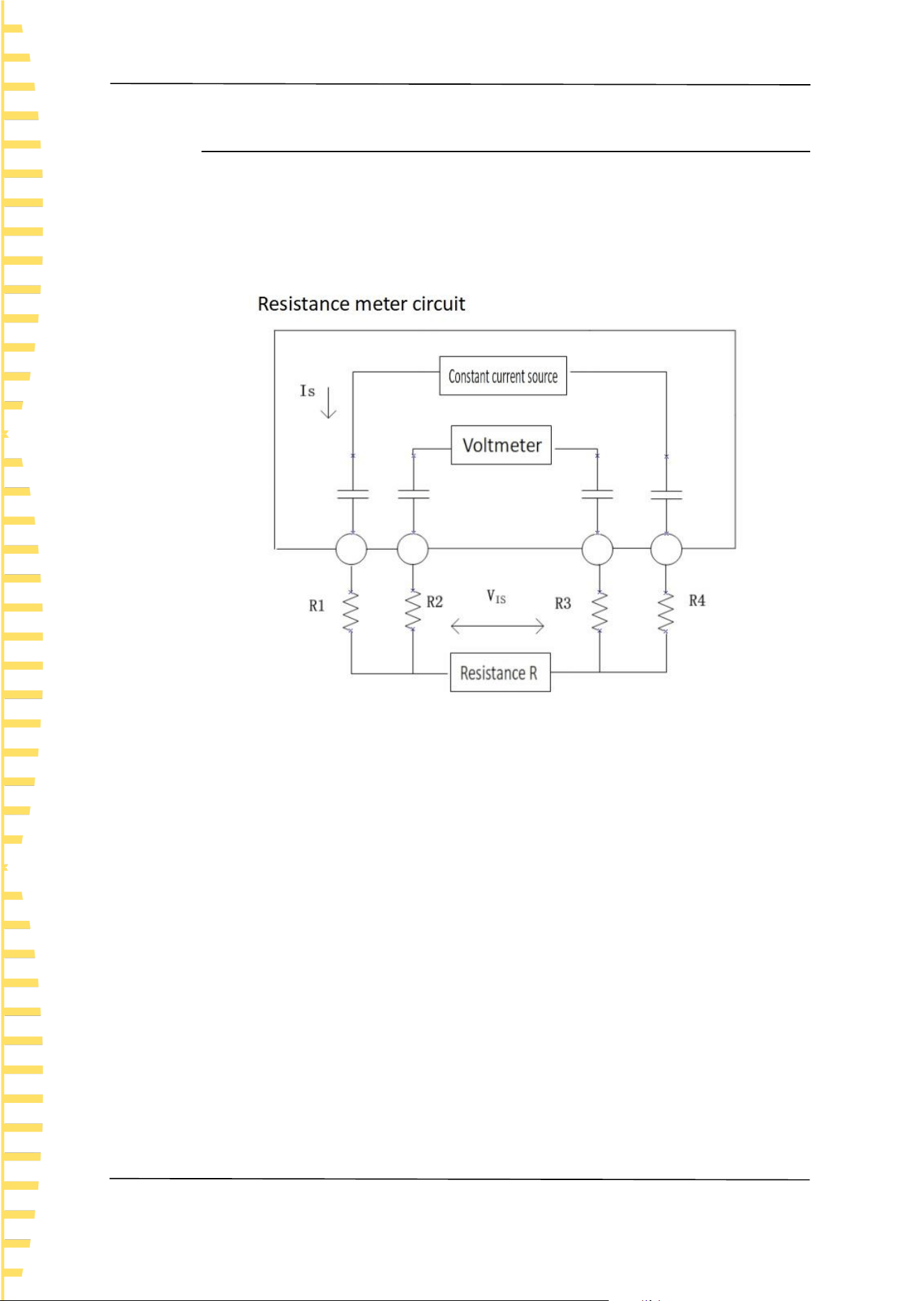
Appendix
EN
HBT4000 series user manual Copyright © Qingdao Hantek Electronic Co., LTD
66
11.2 Appendix B: AC Four Terminal Test Method
This series of internal resistance testers adopts the AC four terminal testing
method, which deduces the wire resistance and contact electrons between the
wire and the test object during the measurement process, making the
measurement results more accurate.
Figure 11-1 Principle diagram of measurement method
Principle of AC four terminal measurement method: As shown in the figure, the
AC current IS is input to the measured object through the current output terminal,
and the voltage drop VIS caused by the impedance of the measured object is
measured on the voltage measurement terminal. At this point, the current
terminal is connected to the internal high impedance voltmeter, so there is almost
no current flowing through the resistance R2 and R3 of the wire resistance and
contact resistance, eliminating the voltage drop on R2 and R3, making the
measurement results more accurate.
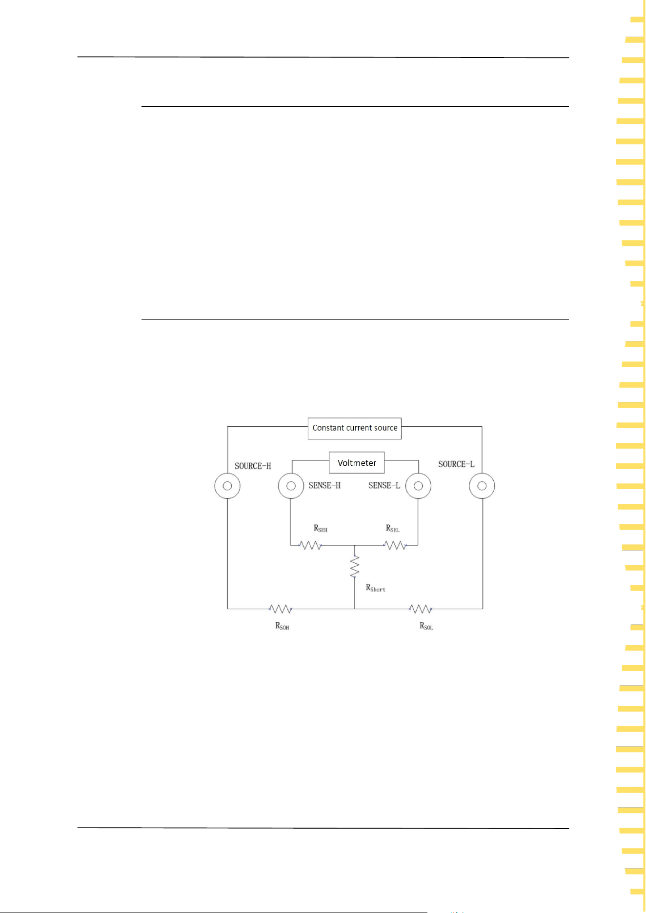
Appendix
EN
Copyright © Qingdao Hantek Electronic Co., LTD HBT4000 series user manual
67
11.3 Appendix C: Performing Zero Adjustment
To remove residual components caused by bias voltage or measurement
environment of this instrument, please perform zero adjustment before
measurement, and the testing accuracy will be specified after zero adjustment.
Zero adjustment refers to the function of subtracting the residual value when
measuring 0 to adjust the zero point, so it is necessary to perform zero
adjustment when connected to 0. Considering that it is unrealistic to connect the
test object without resistance in reality. So, in the actual zeroing process, zeroing
is achieved by establishing a state close to 0. If zero adjustment is not performed
correctly, the correct measurement value cannot be obtained.
11.3.1 Zero adjustment wiring principle
According to Ohm's law E=I * R, in order to establish a state close to 0, it is
necessary to short-circuit directly between SENSE-H (red) and SENSE-L (black).
The voltage between SENSE-H and SENSE-L is approximately 0V, and the specific
calculation is as follows:
Figure 11-2 Zero adjustment schematic diagram
RSEH and RSEL are wiring resistors for SENSE-H and SENSE-L
RSOH and RSOL are the wiring resistors for Source-H and Source-L
RShort is the short-circuit resistance
I0 is the current flowing from SENSE-H to SENSE-L
I is the current flowing from Source-H to Source-L
Then:
E=(I
0
×R
SEL
)+(I
0
×R
SEH
)

Appendix
EN
HBT4000 series user manual Copyright © Qingdao Hantek Electronic Co., LTD
68
=(0×R
SEL
)+(0×R
SEH
)
=0(V)
So, through the above wiring method, the voltage between SENSE-H and SENSE-L
can be correctly maintained at 0V, so it can be adjusted to zero appropriately.
11.3.2 Zero adjustment using clamp type test line
To use a clamp type test wire for zero adjustment, the red and black probes need
to be short circuited. Please connect the test wire as follows:
Figure 11-3 Zero adjustment of clamp type test line
11.3.3 Zero adjustment using needle shaped test lines
To use a needle type test wire to zero, short the internal pin wiring of the red and
black probe. Please connect the test wire as follows:
Figure 11-4 Zero adjustment of needle shaped test line

Appendix
EN
Copyright © Qingdao Hantek Electronic Co., LTD HBT4000 series user manual
69
11.4 Appendix D: Warranty Summary
Qingdao Hantek Electronics Co., Ltd. (hereinafter referred to as Hantek) promises
that the host and accessories of its production instruments will have no material
or process defects during the product warranty period.
During the warranty period, if the product is proven to be defective, Hantek will
provide free repair or replacement for the user. Please refer to the official website
of Hantek or the product warranty card for detailed warranty regulations. To
obtain the full text of repair services or warranty instructions, please contact the
Hantek repair center or local offices.
Except for the warranties provided in this summary or other applicable warranty
cards, Hantek Company does not provide any other express or implied
warranties, including but not limited to any implied warranties of product
tradability and suitability for special purposes. Under no circumstances shall
Hantek be liable for indirect, special or consequential losses.

Address: Building 35, Liandong U Valley, No. 780 Baoyuan Road, High tech Zone, Qingdao,
Shandong Province
Switchboard: 400-036-7077
Email: service@hantek.com
Phone: 0532-55678770, 55678772, 55678773
Postal Code: 266000
Official website: www.hantek.com
Qingdao Hantek Electronic Co., LTD