Loading ...
Loading ...
Loading ...

Part 1 – Introduction
8
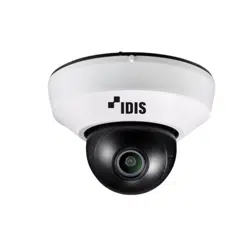
Overview
Product color and design may vary depending on the
model.
Top Cover
Body
1
3
2
4
5
6
1
IR LED
2
Lens
3
Network Port
4
Wall/Ceiling Installation Hole
5
Cable Access Hole
6
Factory Reset Button
• IR LED
A sensor inside the system monitors lighting
levels and activates the IR LED during low-lighting
conditions.
• Lens
Features a xed focus lens.
• Network Port
Connect a network cable with an RJ-45 connector to
this port. If using a PoE switch, you can supply power
to the camera using an ethernet cable. For more
information on PoE switch use, refer to the switch
manufacturer's operation manual. You can congure,
manage, and upgrade this camera and monitor its
images from a remote computer over the network.
For more information on network connection setup,
refer to the IDIS Discovery operation manual.
The following table describes the network cable
specications.
<The network cable specications>
Item Content Note
Connector RJ-45
Ethernet 10/100 Base 10/100 Mbps
Cable
UTP Category 5e or
higher
Maximum
length
100m
PoE IEEE 802.3af, Class 1
• Wall/Ceiling Installation Hole
Used to screw the camera in place on a wall or a
ceiling.
• Cable Access Hole
For routing cables.
• Factory Reset Button
Restores the camera's default factory settings. For
more information, refer to the Factory Reset.
Loading ...
Loading ...
Loading ...