............ www.truemfg.com ............
TABLE OF CONTENTS
Safety Information
Safety Precautions 1
Proper Disposal 2
Connecting Electricity 3
Adapter Plugs 3
Installation / Operation Instructions
Ownership 4
Required Tools 4
Uncrating 4
Location 5
Leveling Cabinet 5
Slide Doors 6
Wire Gauge Cart 7
Sealing Cabinet to the floor 8
Electrical Instructions 9
Direct Draw Draft Arm Installation 9-10
Start-up and Light Switch Location 10
Temperature Control Adjustment 12
Shelving & Bin Divider Installation 13
Storage & Handling 13
Temperature/Pressure/Tapping 14
Maintenance, Care & Cleaning
Draft Beer Problems 15
Changing CO
2
Gas Cylinder 16
Cleaning Bar System 17
Cleaning the Condenser 18
Important Warranty Information 19
Stainless Steel Equipment Care & Cleaning 20-21
Lightbulb Replacement 22
Warranty (U.S.A. and Canada ONLY!) 23
UNDERBAR
REFRIGERATION
CONGRATULATIONS!
You have just purchased the finest commercial
refrigerator available. You can expect many years
of trouble-free operation.
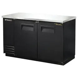
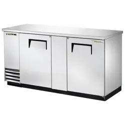
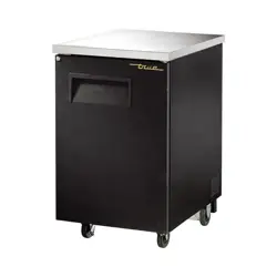
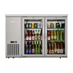
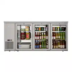
TBB-3G-S
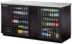
TBB-2
TD-50-18-S
TDD-4
*Spanish, German, French, and Dutch versions included.
TDB-24-48-1-G-1
#894417 • 11/13
INSTALLATION MANUAL FOR
UNDERBAR REFRIGERATION
TRUE FOOD SERVICE EQUIPMENT, INC.
2001 East Terra Lane • O’Fallon, Missouri 63366-4434
(636)-240-2400 • FAX (636)-272-2408 • INT'L FAX (636)272-7546 • (800)-325-6152
Parts Department (800)-424-TRUE • Parts Department FAX# (636)-272-9471
............ www.truemfg.com ............
True Food Service Equipment, Inc.

............ www.truemfg.com ............
SAFETY INFORMATION
True Food Service Equipment, Inc.
1
1
• Thisrefrigeratormustbeproperlyinstalled
andlocatedinaccordancewiththeInstallation
Instructionsbeforeitisused.
• Donotallowchildrentoclimb,standorhangonthe
shelvesintherefrigerator.Theycoulddamagethe
refrigeratorandseriouslyinjurethemselves.
• Donottouchthecoldsurfacesinthefreezer
compartmentwhenhandsaredamporwet.Skin
maysticktotheseextremelycoldsurfaces.
• Donotstoreorusegasolineorotherflammable
vaporsandliquidsinthevicinityofthisoranyother
appliance.
• Keepfingersoutofthe“pinchpoint”areas;
clearancesbetweenthedoorsandbetweenthedoors
andcabinetarenecessarilysmall;becarefulclosing
doorswhenchildrenareinthearea.
NOTE
We strongly recommend that any servicing
be preformed by a qualified individual.
• Unplugtherefrigeratorbeforecleaning
andmakingrepairs.
• Settingtemperaturecontrolstothe0positiondoes
notremovepowertothelightcircuit,perimeter
heaters,orevaporatorfans.
WARNING!
Use this appliance for its intended purpose as described in this Owner Manual.
This cabinet contains fluorinated greenhouse gas covered by the Kyoto Protocol
(please refer to cabinet's inner label for type and volume,
GWP of 134a= 1,300. R404a= 3,800).
How to Maintain Your lkkkfdls
Unit to Receive the Most Efficient and
Successful Operation
You have selected one of the finest commercial refrigeration units made. It is manufactured
under strict quality controls with only the best quality materials available. Your TRUE cooler
when properly maintained will give you many years of trouble-free service.
SAFETY PRECAUTIONS
When using electrical appliances, basic safety precautions should be followed, including the following:

............ www.truemfg.com ............
True Food Service Equipment, Inc.
SAFETY INFORMATION
2
2
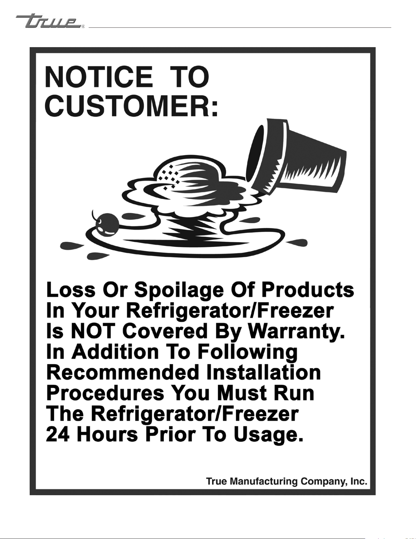
PROPER DISPOSAL OF THE REFRIGERATOR
DANGER!
RISK OF CHILD ENTRAPMENT
USE OF EXTENSION CORDS
NEVER USE AN EXTENSION CORD! TRUE will not warranty any refrigerator that has been connected to an extension cord.
Childentrapmentandsuffocationarenotproblemsof
thepast.Junkedorabandonedrefrigeratorsarestill
dangerous…eveniftheywillsitfor“justafewdays.”If
youaregettingridofyouroldrefrigerator,pleasefollow
theinstructionsbelowtohelppreventaccidents.
Before You Throw Away Your Old Refrigerator or Freezer:
• Takeoffthedoors.
• Leavetheshelvesinplacesothatchildrenmaynot
easilyclimbinside.
Refrigerant Disposal
Youroldrefrigeratormayhaveacoolingsystemthatuses
“OzoneDepleting”chemicals.Ifyou
arethrowingawayyouroldrefrigerator,makesurethe
refrigerantisremovedforproperdisposalby
aqualifiedservicetechnician.Ifyouintentionallyrelease
anyrefrigerantsyoucanbesubjecttofinesand
imprisonmentunderprovisionsoftheenvironmental
regulations.
REPLACEMENT PARTS
• Componentpartsshallbereplacedwithlikecomponents.
• Servicingshallbedonebyauthorizedservicepersonnel,tominimizetheriskofpossibleignitionduetoincorrect
partsorimproperservice.
• Lampsmustbereplacedbyindenticallampsonly.
• Ifthesupplycordisdamaged,itmustbereplacedbyaspecialcordorassemblyavailablefromthemanufactureror
itsserviceagent.
Thepowercordofthisapplianceisequipped
withagroundingplugwhichmates
withastandardgroundingwalloutlet
tominimizethepossibilityofelectricshock
hazardfromthisappliance.
Havethewalloutletandcircuitcheckedbyaqualified
electriciantomakesuretheoutletisproperlygrounded.
Iftheoutletisastandard2-prongoutlet,itis
yourpersonalresponsibilityandobligationto
haveitreplacedwiththeproperlygroundedwalloutlet.
Therefrigeratorshouldalwaysbepluggedinto
it’sownindividualelectricalcircuit,whichhas
avoltageratingthatmatchestheratingplate.
Thisprovidesthebestperformanceandalsoprevents
overloadingbuildingwiringcircuitswhichcouldcausea
firehazardfromoverheatedwires.
Neverunplugyourrefrigeratorbypullingonthepower
cord.Alwaysgripplugfirmlyandpullstraightoutfrom
theoutlet.
Repairorreplaceimmediatelyallpowercordsthathave
becomefrayedorotherwisedamaged.Donotuseacord
thatshowscracksorabrasiondamagealongitslengthor
ateitherend.
Whenremovingtherefrigeratorawayfromthewall,be
carefulnottorolloverordamagethepowercord.
HOW TO CONNECT ELECTRICITY
Do not, under any circumstances, cut or remove the ground prong from the power cord.
For personal safety, this appliance must be properly grounded.
WARNING!
USE OF ADAPTER PLUGS
NEVER USE AN ADAPTER PLUG! Because of potential safety hazards under certain conditions, we strongly recommend against
the use of an adapter plug.
............ www.truemfg.com ............
SAFETY INFORMATION
True Food Service Equipment, Inc.
3
3
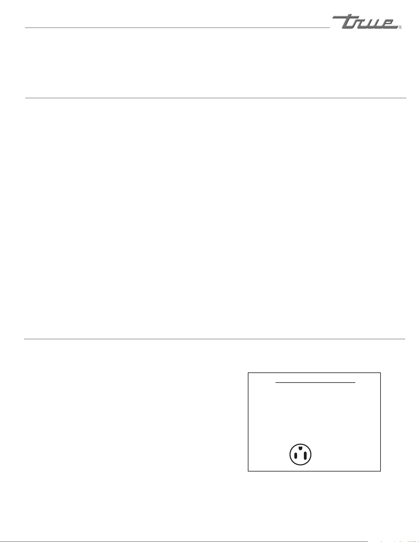
115/60/1
NEMA-5-20R
115/208-230/1
NEMA-14-20R
115/60/1
NEMA-5-15R
208-230/60/1
NEMA-6-15R
NEMA plug confi gurations
T-Series and GDM Freezers
Spec Series same as T-Series
Back Bar
Milk Coolers
TSSU
TPP
TWT
TUC
TRCB
T-Series and GDM Refrigerators
Double Duty, Single Duty, Curved Glass
Horizontal Freezers
GDIM
TAC (Air Curtain)
North America Use Only!
NEMAplugs
TRUEusesthesetypesofplugs.If
youdonothavetherightoutlethave
acertifiedelectricianinstallthecorrect
powersource.
Theincomingpowersourcetothecabinetincludingany
adaptersusedmusthavetheadequatepoweravailable
andmustbeproperlygrounded.Onlyadapterslisted
withULshouldbeused.
............ www.truemfg.com ............
True Food Service Equipment, Inc.
INSTALLATION / OPERATION INSTRUCTIONS
4
4
Toensurethatyourunitworksproperlyfromthefirst
day,itmustbeinstalledproperly.Wehighlyrecommend
atrainedrefrigerationmechanicandelectricianinstall
yourTRUEequipment.Thecost
ofaprofessionalinstallationismoneywellspent.
BeforeyoustarttoinstallyourTRUEunit,carefully
inspectitforfreightdamage.Ifdamageisdiscovered,
immediatelyfileaclaimwiththedeliveryfreightcarrier.
TRUE is not responsible for damage incurred during shipment.
OWNERSHIP
• AdjustableWrench
• PhillipsHeadScrewdriver
• Level
REQUIRED TOOLS
Thefollowingprocedureisrecommendedforuncrating
theunit:
A. Removetheouterpackaging,(cardboardandbubbles
orstyrofoamcornersandclearplastic).Inspectfor
concealeddamage.Again,immediatelyfileaclaim
withthefreightcarrierifthereisdamage.
B. Moveyourunitasclosetothefinallocationas
possiblebeforeremovingthewoodenskid.
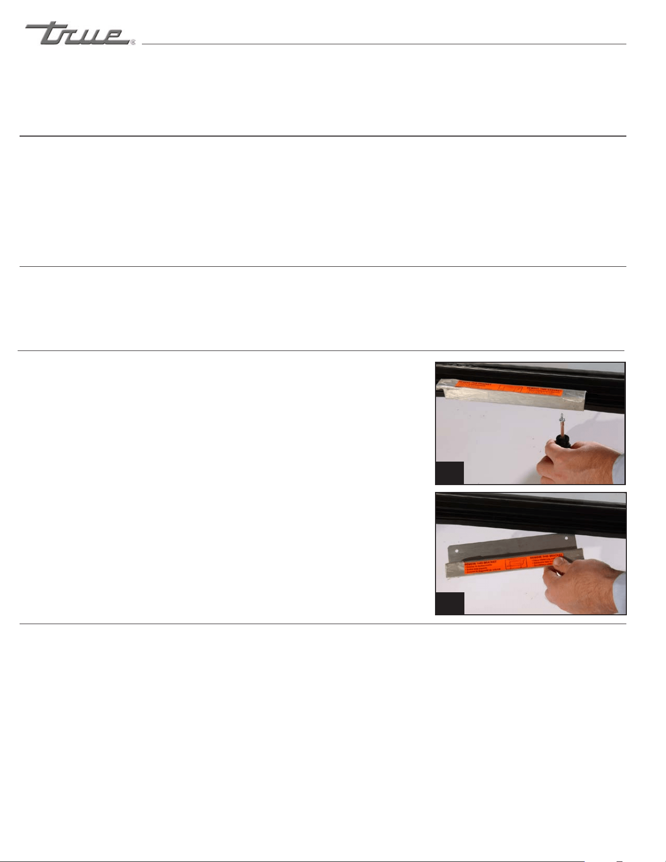
C. Removedoorbracketonswingingglassdoormodels
(seeimage1-2).
NOTE
Keys for coolers with door locks are located in warranty
packets.
UNCRATING
INSTALLATION / OPERATION INSTRUCTIONS
1
2
REMOTE UNITS (This section applies to remotes only!)
• Remotecabinetsmustbeorderedasremote.
Wedonotrecommendconvertingfora
standardselfcontainedtoremotesystem.
• Allremotecabinetsmustbehardwired.
• Nocastorsavailable.
• Allremotecabinetscomestandardusing404A
refrigerant.
• Allremoteunitscomestandardwithexpansion
valve,liquidlinesolenoid,heatedcondensate
pan,anddefrosttimerwhenapplicable.
• ContactTRUETechnicalServiceforBTU
requirements.
• Nowiringnecessarybetweencabinet
andcondensingunit.
• Allremotecondensingunitspurchased
fromTRUEare208/230voltssinglephase.
If you have any questions regarding this section,
please call TRUE at 1-(800)-325-6152.
............ www.truemfg.com ............
INSTALLATION / OPERATION INSTRUCTIONS
True Food Service Equipment, Inc.
5
5
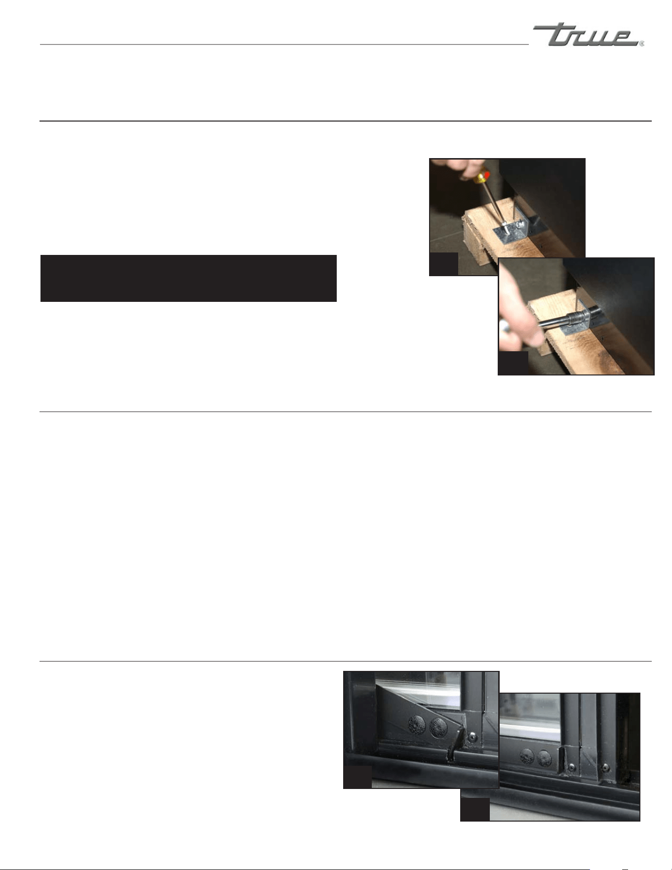
TOOLS REQUIRED:
• Phillipsscrewdriver
• 3/8”socketor3/8”wrench
A. Useaphillipsscrewdiverandremovefourscrews
fromtheL-bracketconnectedtheunittothewood
skid(seeimage1).Thenusea3/8”socketorwrench
andremovetheL-bracketfromtheunit
(seeimage2).
When lifting unit do not use the countertop as
a lifting point. Also remember to leave cabinet upright
for 24 hours before plugging into power source.
B. Removeskidbyunscrewingallbaserailanchor
brackets.Placeskidtotheside.
C. Carefullyuprightcabinet.
D. Applicancetestedaccordingtotheclimateclasses5
and7fortemperatureandrelativehumidity.
LOCATING
Removing
bracket from
skid.
Removing bracket
from cabinet.
1
2
A. Setunitinitsfinallocation.Besurethereisadequate
ventilationinyourroom.Underextremeheat
conditions,(100°F+,38°C+),
youmaywanttoinstallanexhaustfan.
WARNING
Warranty is void if ventilation is insufficient.
B. ProperlevelingofyourTRUEcooleriscriticalto
operatingsuccess(fornon-mobilemodels).Effective
condensateremovalanddooroperationwillbe
effectedbyleveling.
C. Thecoolershouldbeleveledfronttoback
andsidetosidewithalevel.
D. Ensurethatthedrainhoseorhosesarepositionedin
thepan.
E. Freeplugandcordfrominsidethelowerrear
ofthecooler(donotplugin).
F. Theunitshouldbeplacedcloseenoughtothe
electricalsupplysothatextensioncordsarenever
used.
WARNING
Cabinet warranties are void if OEM power cord is tampered
with. True will not warranty any units that are connected to
an extension cord.
LEVELING
Theseinstructionsexplainhowtokeepdoorinopen
position.
A. Slidethedooropen.
B. Latchthedoorintheopenpositionfromthe
backsideofdoor(notchintrack).
C. Doorlatchinimage1isintheopenposition.
D. Doorlatchinimage2isintheclosedposition.
SLIDE DOOR UNITS WITH HOLD OPEN FEATURE
1
2
(Rear view of door & track)
............ www.truemfg.com ............
True Food Service Equipment, Inc.
6
6
INSTALLATION / OPERATION INSTRUCTIONS
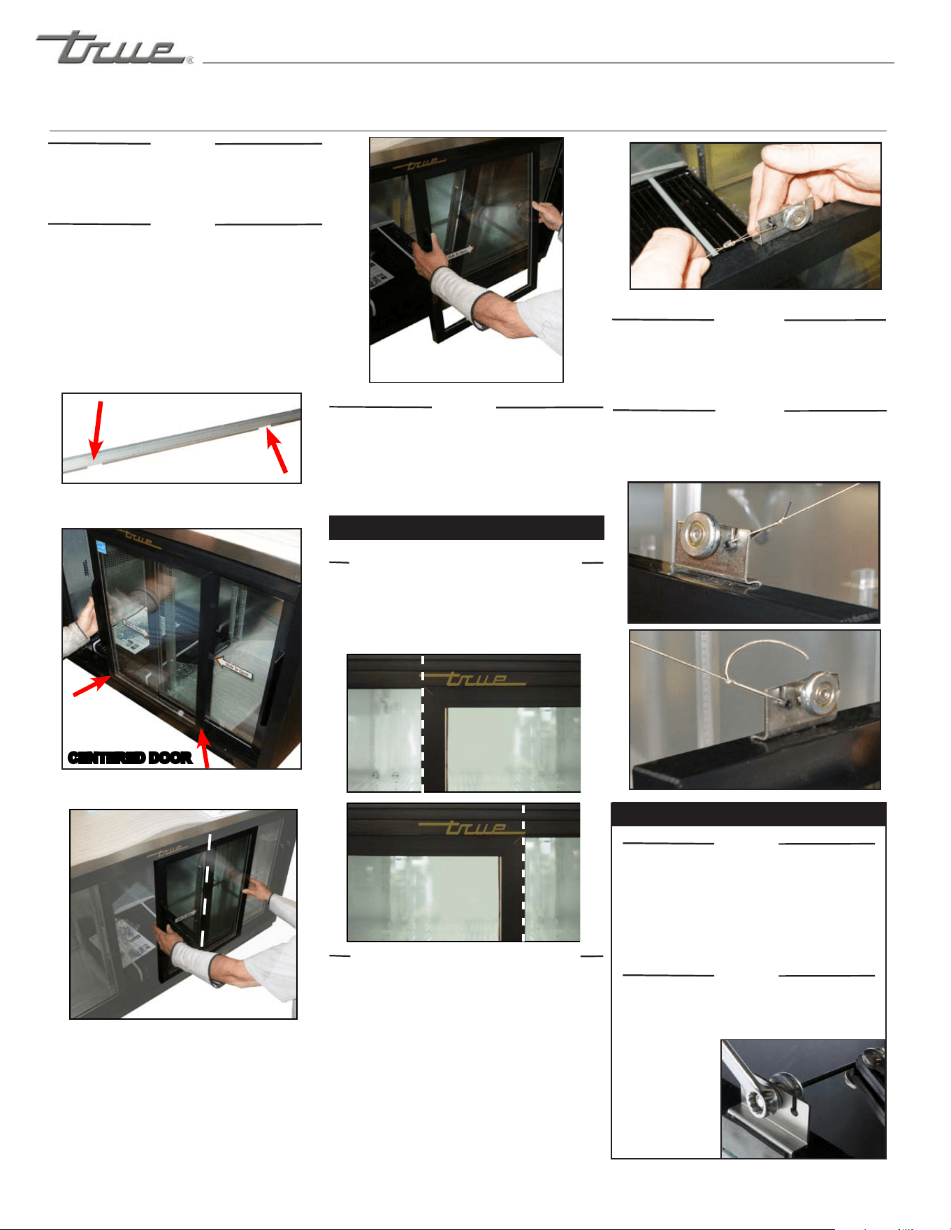
STEP 2
Usinga7/16”wrenchoradjustablewrench
and1/8”allenwrenchloosenrollerandmove
alongslottedhole.Afteradjustmenthasbeen
madetightenthe
rollerintoplace.
Seeimage9.
Image 9
TO ADJUST SLIDE DOOR
STEP 6
Removedoorcordfromrollerbracket.The
blackplastictabholdingthedoorcordslidesout
theback.Slowlyletthedoorcordretractback
tothetrack.Seeimage6.
STEP 7
Whenreinstallingdoormakesuredoorcord
grommetattachestorollerslotclosesttopulley.
(Seeimage7and8).
STEP 1
Aftercabinetisinstalledinafinallocationand
correctlyleveledcheckforanyopeningswhenthe
slidedoorsarecompletelyclosed.Ifthereare
anygaps/openingsbetweenthecloseddoors
andcabinet,thedoorswillneedtobe
adjusted.
Image 3 (Three Door Units ONLY)
STEP 1
Doorscannotberemovedunlessplacedin
specificlocationsstatedintheseinstructions.
STEP 2
Two Door Units:Slidethefrontdoorsoitis
centeredonthecabinet.Thedoorcannotbe
removedunlessitiscentered.Seeimage1for
doorchannelopeningsandimage2for
centeringdoor.
Three Door Units:Slidethemiddledoorto
therightsoitiscenteredwiththeleftedgeof
therightdoor.Seeimage3.
Image 1 (Two Door Units ONLY)
Image 2 (Two Door Units ONLY)
CENTERED DOOR
Image 5 (Three Door Units ONLY)
STEP 5 (Three Door Units Only)
Slideleftdoortotherightsorightedgelinesup
withtherightedgeoftheTrueLogolocatedat
thetopofthedoorframe.Seeimage5b.Then
liftdooroutoftrackasdescribedinStep3.
STEP 4 (Three Door Units Only)
Sliderightdoortotheleftsoleftedgelinesup
withtheleftedgeofTrueLogolocatedabovethe
door.Seeimage5a.Thenliftdooroutoftrackas
describedinStep3.
STEP 3
Aftercenteringthedoorliftitupandtilttopof
doortowardsthebackoftheunitsotherollersare
outofthetopchannel.Swingthebottomofthe
dooroutofthebottomchannel.Thenremovethe
doorandsetitdown.Seeimage4.
(TWO DOOR UNITS SKIP TO STEP 6)
Image 4
Image 6
SLIDE DOORS
Image 5a
Image 5b
Image 7 (Door closing to the right)
Image 8 (Door closing to the left)

............ www.truemfg.com ............
True Food Service Equipment, Inc.
7
7
CONDUCTORS AND CIRCUITS
Wire Gauge for 2% Voltage Drop in Supply Circuits.
115 Volt Distance In Feet To Center of Load
Amps 20 30 40 50 60 70 80 90 100 120 140 160
2 14 14 14 14 14 14 14 14 14 14 14 14
3 14 14 14 14 14 14 14 14 14 14 14 12
4 14 14 14 14 14 14 14 14 14 12 12 12
5 14 14 14 14 14 14 14 12 12 12 10 10
6 14 14 14 14 14 14 12 12 12 10 10 10
7 14 14 14 14 14 12 12 12 10 10 10 8
8 14 14 14 14 12 12 12 10 10 10 8 8
9 14 14 14 12 12 12 10 10 10 8 8 8
10 14 14 14 12 12 10 10 10 10 8 8 8
12 14 14 12 12 10 10 10 8 8 8 8 6
14 14 14 12 10 10 10 8 8 8 6 6 6
16 14 12 12 10 10 8 8 8 8 6 6 6
18 14 12 10 10 8 8 8 8 8 8 8 5
20 14 12 10 10 8 8 8 6 6 6 5 5
25 12 10 10 8 8 6 6 6 6 5 4 4
30 12 10 8 8 6 6 6 6 5 4 4 3
35 10 10 8 6 6 6 5 5 4 4 3 2
40 10 8 8 6 6 5 5 4 4 3 2 2
45 10 8 6 6 6 5 4 4 3 3 2 1
50 10 8 6 6 5 4 4 3 3 2 1 1
Wire Gauge for 2% Voltage Drop in Supply Circuits.
230 Volt Distance In Feet To Center of Load
Amps 20 30 40 50 60 70 80 90 100 120 140 160
5 14 14 14 14 14 14 14 14 14 14 14 14
6 14 14 14 14 14 14 14 14 14 14 14 12
7 14 14 14 14 14 14 14 14 14 14 12 12
8 14 14 14 14 14 14 14 14 14 12 12 12
9 14 14 14 14 14 14 14 14 12 12 12 10
10 14 14 14 14 14 14 14 12 12 12 10 10
12 14 14 14 14 14 14 12 12 12 10 10 10
14 14 14 14 14 14 12 12 12 10 10 10 8
16 14 14 14 14 12 12 12 10 10 10 8 8
18 14 14 14 12 12 12 10 10 10 8 8 8
20 14 14 14 12 10 10 10 10 10 8 8 8
25 14 14 12 12 10 10 10 10 8 8 6 6
30 14 12 12 10 10 10 8 8 8 6 6 6
35 14 12 10 10 10 8 8 8 8 6 6 5
40 14 12 10 10 8 8 8 6 6 6 5 5
50 12 10 10 8 6 6 6 6 6 5 4 4
60 12 10 8 6 6 6 6 6 5 4 4 3
70 10 10 8 6 6 6 5 5 4 4 2 2
80 10 8 8 6 6 5 5 4 4 3 2 2
90 10 8 6 6 5 5 4 4 3 3 1 1
100 10 8 6 6 5 4 4 3 3 2 1 1
INSTALLATION / OPERATION INSTRUCTIONS

............ www.truemfg.com ............
True Food Service Equipment, Inc.
8
8
Step 1 - Position Cabinet
Allowoneinchbetweenthewallandrearofthe
refrigeratedBarEquipmenttoassureproperventilation.
ForGlass&PlateChillers/Frosters3inchesbetweenthe
wallandrearofthecabinetwillassureproperventilation.
Step 2 - Level Cabinet
Cabinetshouldbelevel,sidetosideandfronttoback.
Placeacarpenter’slevelintheinteriorfloorinfour
places:
A. Positionlevelintheinsideflooroftheunitnearthe
doors.(Levelshouldbeparalleltocabinetfront).
Levelcabinet.
B. Positionlevelattheinsiderearofcabinet.(Again
levelshouldbeplacedparalleltocabinetback).
C. PerformsimilarprocedurestostepsA&Bbyplacing
theleveloninsidefloor(leftandrightsides-parallel
tothedepthofthecooler).Levelcabinet.
Step 3
Drawanoutlineonthebaseonthefloor.
Step 4
Raiseandblockthefrontsideofthecabinet.
Step 5
Applyabeadof“NSFApprovedSealant”,(seelistbelow),
toflooronhalfinchinsidetheoutlinedrawn.Thebead
mustbeheavyenoughtosealtheentirecabinetsurface
whenitisdownonthesealant.
Step 6
Raiseandblocktherearofthecabinet
Step 7
ApplysealantonfloorasoutlinedinStep5onother
threesides.
Step 8
Examinetoseethatcabinetissealedtoflooraround
entireperimeter.
Note:
Asphaltfloorsareverysusceptibletochemicalattack.A
layeroftapeonthefloorpriortoapplyingthesealant
willprotectthefloor.
NSF Approved Sealants:
1.MinnesotaMining#ECU800Caulk
2.MinnesotaMining#ECU2185Caulk
3.MinnesotaMining#ECU1055Bead
4.MinnesotaMining#ECU1202Bead
5.ArmstrongCork-RubberCaulk
6.ProductsResearchCo.#5000RubberCaulk
7.G.E.SiliconeSealer
8.DowCorningSiliconeSealer
SEALING CABINET TO FLOOR
INSTALLATION / OPERATION INSTRUCTIONS
............ www.truemfg.com ............
9
9
True Food Service Equipment, Inc.
............ www.truemfg.com ............
INSTALLATION / OPERATION INSTRUCTIONS
A. Beforeyournewunitisconnectedtoapowersupply,
checktheincomingvoltagewithavoltmeter.If
anythinglessthan100%oftheratedvoltagefor
operationisnoted,correctimmediately.
B. Allunitsareequippedwithaservicecord,andmust
bepoweredatproperoperatingvoltageatalltimes.
Refertocabinetdataplateforthisvoltage.
TRUErecommendsthatasoleusecircuitbededicated
fortheunit.
WARNING
Compressor warranties are void if compressor burns out due
to low voltage.
WARNING
Power supply cord ground should not be removed!
WARNING
Do not use electrical appliances inside the food storage
compartments of the appliances unless they are of the
type recommended by the manufacturer.
NOTE
To reference wiring diagram - Remove front louvered grill,
wiring diagram is positioned on the inside cabinet wall.
ELECTRICAL INSTRUCTIONS
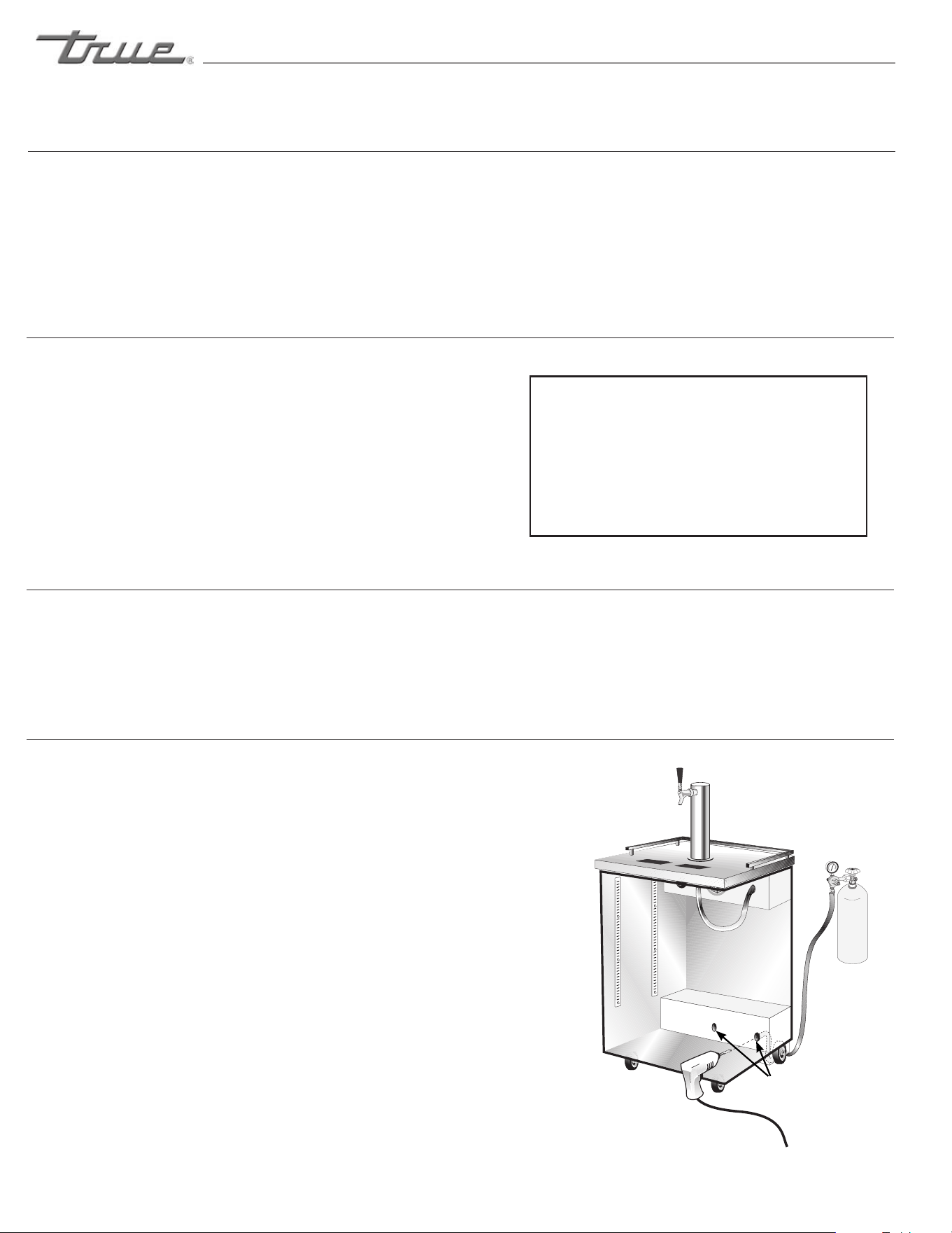
Ondirectdraws,thedrainislocatedatthefront
ofthecabinet.Toplumbinthedrain,connect
3
⁄4"
(2cm)P.V.C.pipetothe
3
⁄4"(2cm)barbedfitting
supplieswiththeunit.
CO
2
PRESSURE
Mobiletapsters,toretaincompletemobility,the
CO
2
tank(uptofivepoundsinsize)canbe
placedinsidethecooler(strapholdersfurnished).
CAUTION
Filled CO
2
tanks are potentially dangerous because
of the pressure they contain. If you are unfamiliar
with their use or the use of the CO
2
regulator, seek
information from your local distributor, or your local
beverage man before proceeding.
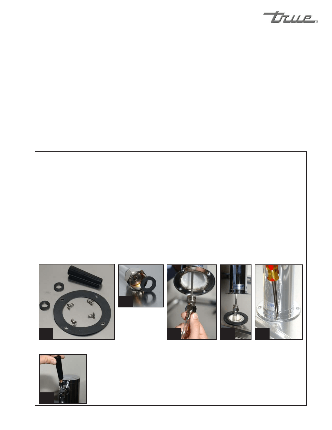
INSTALL DRAFT ARM
Placerubberwasheroverdraftarmmounting
holesincabinet,putbeerlineconnectordown
throughhole.Next,securedraftarmwithfour
screws.(Seeimages1-6)
DIRECT DRAW DRAFT ARM INSTALLATION
CONTINUED ON
NEXT PAGE...
Draft arm install contents.
(Draft arm not shown)
Beer line
connector.
Thread beer line connector to draft arm and secure draft arm
to cabinet with rubber gasket under the draft arm.
Thread beer
draft arm
handle onto
the draft
arm.
1
2
3 4 5
6
............ www.truemfg.com ............
10
10
True Food Service Equipment, Inc.
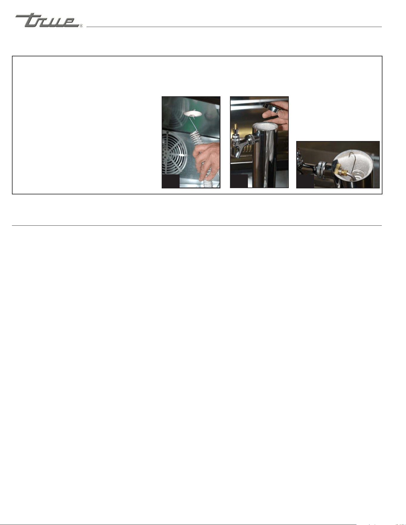
INSTALL DRAFT ARM continued...
Insertairhose(oneinchplastictube)
indraftarm,beingcarefulnottodisturb
insulation.Removetopcoverofdraftarm
andattachairhosecliptotheinsulating
sleeveatthetopofthedraftarm.Replace
topcover.Theairhoseclipwillassurethat
thehoseremains
inproperplaceatalltimes,keeping
thebeerfaucetcold.(Seeimage7-9)
............ www.truemfg.com ............
INSTALLATION / OPERATION INSTRUCTIONS
DIRECT DRAW DRAFT ARM INSTALLATION
CONTINUED...
A. Thecompressorisreadytooperate.Pluginthe
cooler.
B. TemperaturecontrolsetatNo.4positiongives
refrigeratorsanapproximatetemperatureof35°Fand
glasschillerfrostershaveanapproximatetemperatureof
0°F.Allowunittofunctionseveralhours,completely
coolingcabinetbeforechangingthecontrolsetting.
C. Excessivetamperingwiththecontrolcouldleadto
servicedifficulties.Shoulditeverbecomenecessary
toreplacetemperaturecontrol,besureitisordered
fromyourTRUEdealerorrecommendedservice
agent.
D. GoodairflowinyourTRUEunitiscritical.Be
carefultoloadproductsothatitneitherpresses
againstthebackwall,norcomeswithinfourinchesof
theevaporatorhousing.Refrigeratedairoffthecoil
mustcirculatedownthebackwall.
LIGHT SWITCH LOCATION:
Theswitchislocatedonthefrontoftheevaporator
housingtowardthefrontofthecabinet.Openthefront
doorsandtheswitchwillbevisibleclosetotheceiling
thecabinet.
NOTE
If the unit is disconnected or shut off, wait five minutes
before starting again.
RECOMMENDATION
Before loading product we recommend you run your TRUE
unit empty for two to three days. This allows you to be sure
electrical wiring and installation are correct and no shipping
damage has occurred. Remember, our factory warranty does
not cover product loss!
REPLACEMENT PARTS
TRUE maintains a record of the cabinet serial number for
your cooler. If at any time during the life of your cooler, a
part is needed, you may obtain this part by furnishing the
model number and serial number to the company from whom
you purchased the cooler. Call Toll-Free: (800)-424-TRUE
(Direct to Parts Department). (800)-325-6152 (U.S.A.
& Canada only) or call: (636)-240-2400.
STARTUP
7 8 9

............ www.truemfg.com ............
True Food Service Equipment, Inc.
11
11
DANFOSS ELECTRONIC TEMPERATURE CONTROL
GENERAL SEQUENCE OF OPERATION
YOUR TRUE GLASS & PLATE CHILLER MAY USE
AN ELECTRONIC CONTROL - 115V/60HZ ONLY
IF YOUR CABINET IS PRODUCED WITH AN ELECTRONIC CONTROL, THERE MAY BE
UP TO A 20 MINUTE DELAY WHEN CABINET IS PLUGGED IN.
If the serial number on your cabinet is higher than listed below, it was produced with
an electronic control.
1.Cabinetispluggedin.
a.InteriorlightswillilluminateofGlassDoorModelsonly.Iflightsdonotcomeonverifythelightswitchisinthe
“ON”position.Soliddoorcabinetmayormaynothavelightsthatmaybecontrolledbythedoorswitch.
b.CabinetwillstartinaDefrostCycle.
2.DuringtheinitialDefrostCycle,theevaporatorfan(s)andthecompressorwillremainoforaminimumof4
minutes.
a.AftertheDefrostCycletherewillbea2minutedelay.
b.Afterthe2minutedelaythecompressorwillstart.
c.eevaporatorfanswillremainoforanadditional3minutes.
3.eDanfosscontrolwillcyclethecompressorandtheevaporatorfan(s)onandotogether.
a.etemperaturecontrolissensingthedischargeairtemperature.
b.etemperaturecontrolshouldbesetonthe#4or#5.
c.ewarmestsettingis#1and#0istheoposition.
d.ethermometerisdesignedtoreadanddisplayacabinettemperaturenotaproducttemperature.iscabinet
temperaturemayreecttherefrigerationcycledeterminedbythetemperaturecontrol.emostaccurate
temperatureonacabinetsoperationistoverifytheproducttemperature.
4.eDanfosscontrolispreprogrammedtoinitiatedefrostevery4hoursofcompressorruntime.
a.Atthistimethecompressorandevaporatorfan(s)willturnoandtheevaporatorcoilheateranddraintube
heaterwillbeenergized.Somecabinetsmayalsochangetherotationofthereversingcondenserfanmotor.
b.Onceapreprogrammedtemperatureoftheevaporatorcoilisreached,theDefrostCyclewillterminateandthe2
minutedelaywilloccur.
c.Afterthe2minutedelaythecompressorwillrestart.
d.eevaporatorfanswillremainoforanadditional3minutes.
T-24-GC / T-24-GC-S
S# 7721857
T-36-GC / T-36-GC-S
S# 7218795
T-50-GC / T-50-GC-S
SN 7147406
............ www.truemfg.com ............
True Food Service Equipment, Inc.
12
12
TERMS:
Cut-out-Temperaturesensedbythe
controllerthatshutsthecompressor
off.
Cut-in-Temperaturesensedbythe
controllerthatturnsthecompressor
on.
REQUIRED TOOLS
• PhillipsHeadScrewdriver
• 5/64"or2mmAllenWrench
• T-7TorxWrench
STE P 1
Unplugthecooler.
STE P 2
Removethescrewsthatsecurethe
temperaturecontroltotheinsetbox.
S T E P 3
Pulloutgentlyfromcabinet.
S T E P 4
Forhighelevationinstallations,it
maybenecessaryto"warm-up"the
setpoints.Tomaketheadjustment,
inserttheappropriatetoolineach
adjustmentscrewandturn1/4ofa
revolutionclockwise(totheright).
Thisprocedurewilladjustboth
thecut-inandcut-outabout2°F
warmer.
S T E P 5
Makesuretoreconnectthepink
wiretotheproperspadeterminal
whenreinstalling.
NOTE:
Mechanical temperature
controllers are affected when
functioning at high altitude. The
cut-in and cut-out
temperatures will be colder than
when the controller functions
closer to sea level
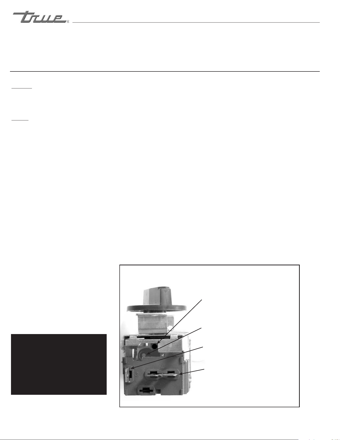
Danfoss Temperature Control (High Altitude Adjustment Only!)
Cut-out Adjustment Screw Allen (5/64"
or 2 mm) (clockwise for warmer)
Cut-in Adjustment Screw Torx (T-7)
(clockwise for warmer)
Compressor Connection (pink)
Compressor Connection (pink)
TEMPERATURE CONTROL ADJUSTMENT FOR
HIGH ALTITUDE ONLY!
INSTALLATION / OPERATION INSTRUCTIONS
............ www.truemfg.com ............
True Food Service Equipment, Inc.
13
13
O
F
F
9
8
7
6
5
4
3
2
1
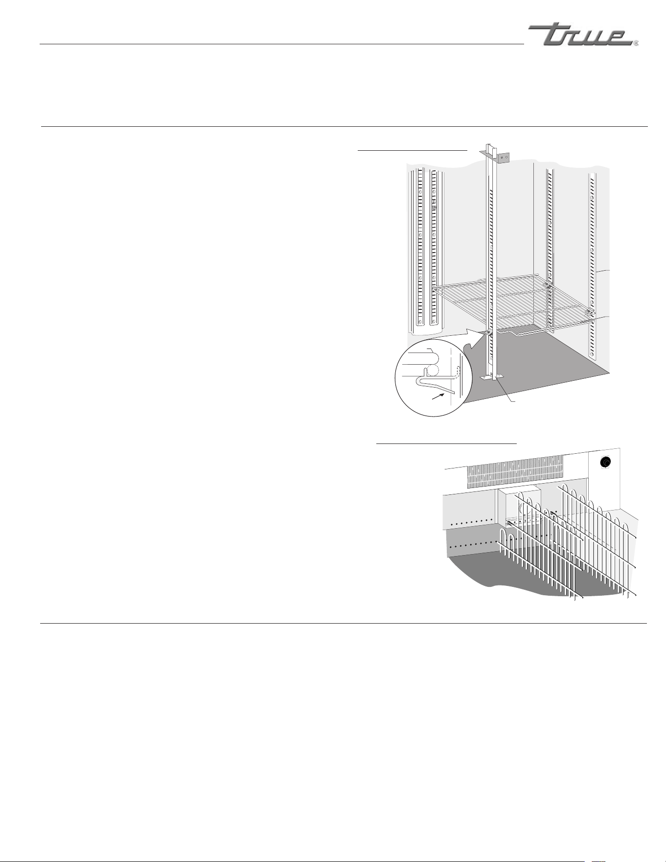
SHELVING and BIN DIVIDER INSTALLATION /
OPERATION
SHELF INSTALLATION:
A. Hookshelfclipsontoshelfstandards.
B. Positionallfourshelfclipsequalindistancefromthe
floorforflatshelves.
C. Shelvesareorientedsothatcrosssupportbarsare
facingdown.
D. Placeshelvesonshelfclipsmakingsureallcorners
areseatedproperly.
HORIZONTAL BOTTLE COOLER BIN DIVIDER
INSTALLATION:
Horizontalbottlecoolersareshippedwithbindividers
inplace.Ifitisnecessarytoadjustspacingthefollowing
procedureisrecommended.
A. Dividersarespringloaded-pushdividertowardsrear
ofthecoolertoreleasefromfrontgrommetedholes.
B. Lineupdividerfrontpegswithdesiredholesand
punchthroughinteriortapeliningofbothtopand
bottomholes-bottompegfirst(frontholesaretaped
overtoimproveinsulationvalues).
C. Removedividerfromthefrontholesandlineup
regularandspringloadedrearpegswithholesinline
withthosedesiredinfront.Insertasfaraspossible
andmaneuverfrontpegsinplace.
SHELF INSTALLATION
BIN DIVIDER INSTALLATION
NOTE
Divider
positioned
in front of
mechanical box
requires specific
notch cut out.
Draftbeershouldbetreatedasafoodproduct.In
mostinstancesdraftbeerisnotpasteurized.Itisvery
importantthatyoustoreandhandleitproperly.
Followthesestepstoensurethehighestqualityand
consumersatisfaction.
• Draftbeershouldbeimmediatelystoredina
refrigeratedcabinet.
• Draftbeerproductshavearecommendedshelflife.
Ifyouhavequestionsregardingtheshelflifeofany
ofyourdraughtproducts,pleaseconsultwithyour
supplyingdepotorrespectiveBrewerrepresentative.
• Kegsshouldbestoredseparatelyfromfoodproducts.
Ifyourcoolerisusedtorefrigeratedraughtandfood
products,itisveryimportantthatthefoodnotbe
storednearoronthekegs.
• Kegstorageanddispensingareasshouldbekeptclean
topreventanypossibilityofcontaminatingyour
draughtproducts.
STORAGE AND HANDLING
Shelf
Clip
Shelf
Shelf
Pillaster
(I-beam)
Shelf
Standards
INSTALLATION / OPERATION INSTRUCTIONS
............ www.truemfg.com ............
True Food Service Equipment, Inc.
14
14
Dispensing pressures differ according to:
• Thetypeofdraftdispensingsystem
• Thelengthofdraftdispensingline
• Theactualproduct-somerequiremore,
somerequireless
• Thetemperatureoftheproduct
• Thepressurizingagent:airpressure,
CO
2
orspecialblendedgases.
PRESSURE
• Correcttemperatureisakeyfactortoconsiderinstoring
anddispensingdraftbeer.Toocoolortoowarmmaycause
flavorloss,offtasteanddispensingproblems.
Helpful Hints on Controlling Temperature
• Keepathermometerhandy
• Monitortemperatureofdraftinyourcooler
andatthetap
• Keepcoolerdoorclosedasmuchaspossible
toavoidtemperaturefluctuation
• Regularmaintenanceofrefrigerationequipment
isrecommended
TEMPERATURE
Helpful Hints On Maintaining The Correct Pressure:
• Knowwhichpressurizingagentto
useonwhichproductandwhy.
• Monitoryourregulatorstoensure
appliedpressureremainsconstant.
• Keepequipmentingoodrepair.
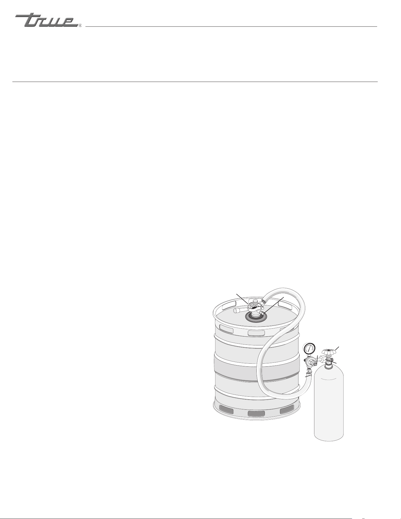
Donotagitatethekegsunnecessarily.Ifexcessiveagitation
occursallowkegstosettlefor1to2hoursbeforetapping.
Priortotappingthekeg,ensurethatallbeerfaucetinthe
servinglocationareintheoffposition.Completelyremove
thedustcover(identificationcap)fromthekeg.
TAPPING
isinstructionisTRUE’s
recommendedprocedureforinstallinga
remoteCO
2
container.
REQUIRED TOOLS
•Pliers
•PowerDrill
•SiliconeSealer
•Drillbit,1/2”
STEP 1
Removeblackknockoutplugwithapair
ofpliers.
NOTE:
KnockoutplugforCO
2
linecanbe
locateintwodierentareas.View
diagramtolocatethesetwoareas.
STEP2
Usedrillandbittoboreholestraight
backthroughwallintocompressor
compartment.
STEP3
SnakeCO
2
linethroughholedown
andaroundexitingbehindrearcastor
underneathreargrill.
STEP4
SealholearoundCO
2
linewithsilicone
sealertopreventcoldairleakage.
TDD-1 CO
2
KNOCK-OUT
O
F
F
9
8
7
6
5
4
3
2
Knockout Plug
can be located at
either location.
INSTALLATION / OPERATION INSTRUCTIONS

............ www.truemfg.com ............
True Food Service Equipment, Inc.
15
15
Flat Beer - Description: Foamy head
disappears quickly. Beer lacks usual zestful
brewery fresh flavor.
• CO
2
turnedoffwhennotinuse.
• Contaminatedairsource(associatedwith
compressedair).
• Greasyglasses.
• Notenoughpressure.
• Pressureshutoffduringnight.
• Loosetaporventconnection.
• Sluggishpressureregulator.
• Obstructioninlines.
False Head - Description: Large soap-like
bubbles, head dissolves very quickly.
• Dryglasses.
• Improperpour.
• Pressurerequireddoesnotcorrespondto
beertemperature.
• Coilsordirectdrawbeerlineswarmerthan
beerinkeg.
• Smalllinesintolargefaucetshanks.
• Beerdrawnimproperly.
Wild Beer - Description: Beer, when drawn,
is all foam and not enough liquid beer.
• Beerdrawnimproperly.
• Faucetinbadorworncondition.
• Kinks,dents,twistsorotherobstructionsin
line.
• Trapsinbeerlines.
• Beertoowarminkegsorlines.
• Toomuchpressure.
• Creepinggaugecausingtoomuchpressure.
Cloudy Beer - Description: Beer in the glass
appears hazy. Not clear.
• Dirtyglassorfaucet.
• Beeroverchilled.
• Beertemperaturevarianceinkeg(Beermay
havewarmedupatsometime).
• Hotspotsinbeerlines.
• Cuttingbeerthroughfaucet.
• Beerlineinpoorcondition.
• Dirtylines.
• Beerthathasbeenfrozen.
Bad Taste
• Dirtyfaucet.
• Oldordirtybeerlines.
• Failuretoflushbeerlineswithwaterafter
eachemptykeg.
• Unsanitaryconditionsatbar.
• Foulairordirtinlines.
• Oilyair;greasykitchenair.
• Temperatureofpackagetoowarm.
• Dryglasses
DRAFT BEER PROBLEMS
To minimize draft beer problems, always follow the recommended instructions for temperature
and CO
2
pressures from your beer supplier.
INSTALLATION / OPERATION INSTRUCTIONS
MAINTENANCE, CARE & CLEANING
............ www.truemfg.com ............
True Food Service Equipment, Inc.
16
16
Follow these instructions at ALL times when you
replace a CO
2
gas cylinder:
1. Closecylinderat"A".
2. Removetap"D"frombarrel.Pullpressurerelease
ringonbodyoftaptoreleasepressureremainingin
line.(donotclose"C")
3. Removeorloosenregulatorkey"B"byturning
counterclockwise.
4. Removeregulatorfromusedcylinderat"E".
5. Removedustcapfromnewgascylinderat"E"and
cleardustfromoutletbyopeningandclosingvalve
"A"quicklyusingappropriatewrench.
6. Attachregulatortonewcylinderat"E".(usenew
fiber/plasticwasher,ifrequired).
7. Openvalve"A"alltheway.
8. Closevalve"C".
9. Adjustregulatorkey"B"byturningclockwisetoset
pressure.(checksettingbyopening"C"andpulling
andreleasingthering"F"onthepressurerelease
valveonthebodyofthetap)
10. Tapbarrelat"D"withvalve"C"open.
NOTE
Don't lay CO
2
cylinders flat.
Don't drop CO
2
cylinders.
It requires 1/2 pound CO
2
to dispense 1/2 barrel of beer
at 38˚F with 15 pounds pressure on barrel.
PRESSURE ADJUSTMENT ON CO
2
REGULATOR
Increasing Pressure:
1. Closeregulatorshut-off"C".
2. Turnregulatorkey"B"clockwiseandmakesetting.
3. Tapgaugeforaccuratereading.
4. Openregulatorshut-off"C"anddrawbeer.
Decreasing Pressure:
1. Closeregulatorshut-off"C".
2. Untapbarrelat"D"andtobleedline,activatetap
handle.Leaveinopenposition.
3. Slowlyopenregulatorshut-off"C"and
simultaneouslyturnregulatorkeycounter-clockwise
tozeroreading.
4. Closeregulatorshut-off"C"andsetpressureby
turningregulatorkeyclockwise.Checksettingby
openingandclosingvalve"C".
5. Closetaphead"D".(putin"OFF"position)
6. Tapbarrelat"D"andopenregulatorshut-off"C".
CHANGING CO
2
GAS CYLINDER
A
B
C
D
E
F
MAINTENANCE, CARE & CLEANING
............ www.truemfg.com ............
True Food Service Equipment, Inc.
17
17
Draughtdispensers,regardlessofdesign,mustbecleaned
atleasteverytwoweeks.Flushingyourdraughtdispenser
withwateronlyisnotenough.
NOTE
Use cleaners approved by your beer supplier and follow their
instructions. If you are using the cleaning kit purchased from
TRUE follow these instructions:
Exacting cleanliness should be constantly maintained in
your dispenser so that your draught beer will be at its best
when served. Although the beer in the barrel is in excellent
condition, it can become less satisfying as it is drawn
through the beer line and faucet if they are not kept clean.
Prepare Solution:
• Add1/2ounce(19grams)oflinecleaningpowderto
eachquartofwater,coldorwarm.
Cleaning:
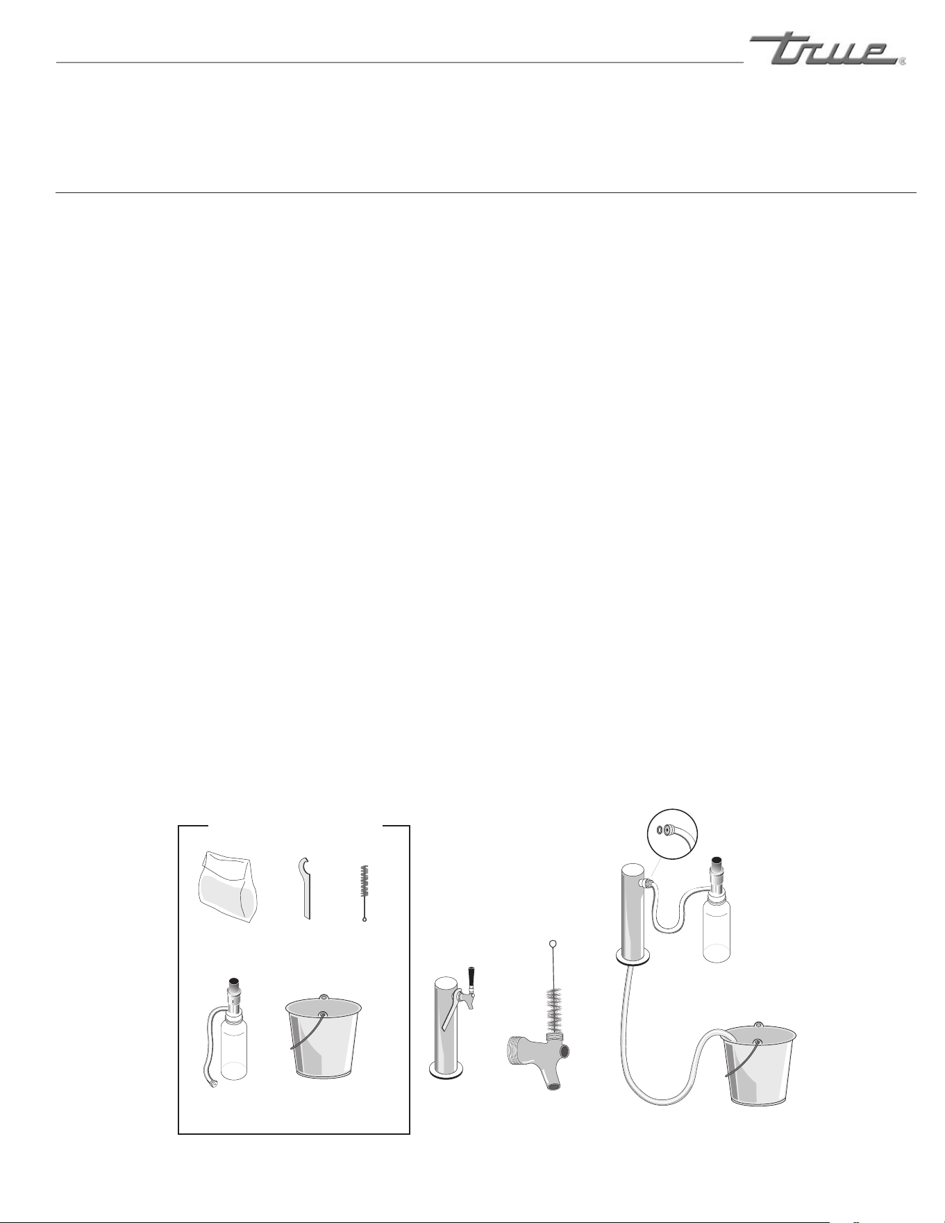
1. Disconnecttapfrombarrel.Removebeerfaucetwith
spannerwrenchunscrewhandleandremovevalve
assembly(fig.1).
2. Puttapandfaucetpartsinabucketwithcleaning
solutiontosoak.
3. Usesmallbrushtocleanbeerfaucetparts
(fig.2).
4. Rinsepartsthoroughly.
5. FillpumpbottlewithDBKsolution.
6. Attachhosefrompumpbottletobeercolumntap
outlet(besurerubbergasketisinplacetoprevent
leakage)-allowtaptodraininbucket(fig.3).
7. Pumpsolution(2-3timesfrombottlethroughthe
lineuntilitstartstoflowoutthebeerline.
Wait 10 minutes while cleaning solution works
on the lines.
8. Pumpexcesssolutionthroughlines.
9. Rinsebucket,pumpbottleandhosethoroughlywith
cleancoolwater.
10. Fillpumpbottlewithcleancoolwaterandpump
throughlinesuntilwaterrunsclear.
11. Whencrystalclearwatercomesthrough,you'reready
toassembleandreattachfaucetandre-tapthebarrel.
12.Drawthewaterfromthebeerline;nowyou'reready
toservebreweryfresh,goldenbeer.
NOTE
Keeping your dispenser and all its parts clean and odor
free will help you to serve beautiful foam topped glasses of
delicious satisfying draught beer.
CLEANING BAR SYSTEM
fig. 1 fig. 2 fig. 3
Beer Tap Cleaning Kit
Required Tools
linecleaning
powder
Spanner
wrench
Brush
Pumpbottle
andtub
Bucketand
freshwater
MAINTENANCE, CARE & CLEANING
............ www.truemfg.com ............
True Food Service Equipment, Inc.
18
18
MAINTENANCE, CARE & CLEANING
CLEANING THE CONDENSER COIL
When using electrical appliances, basic safety precautions should be followed, including the following:
T
M
C
TRUE
REQUIRED TOOLS
•PhillipsScrewdriver
•StiffBristleBrush
•AdjustableWrench
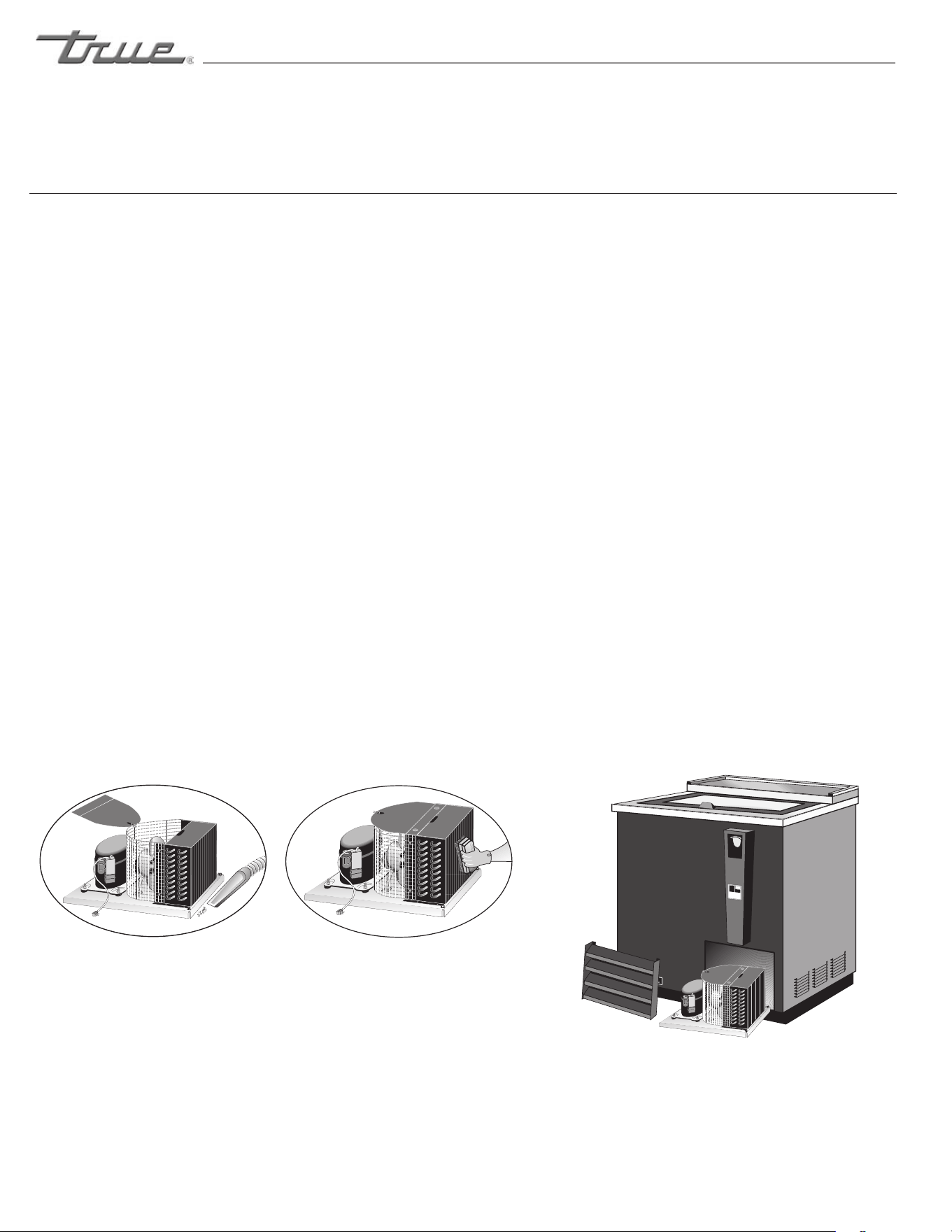
STEP 1
Disconnectpowertounit.
STEP 2
Takeofflowergrillassemblybyremovingallscrews.
STEP 3
Removeboltsanchoringcompressorassemblytoframe
railsandcarefullyslideout.(tubeconnectionsare
flexible)
STEP 4
Cleanoffaccumulateddirtfromcondensingcoilwitha
stiffbristlebrush.
STEP 5
Liftcardboardcoverabovefanatplasticplugsand
carefullycleancondensercoilandfanblades.
STEP 6
Afterbrushingcondensercoilvacuumdirtfromcoil,and
interiorfloor.
STEP 7
Replacecardboardcover.Carefullyslidecompressor
assemblybackintopositionandreplacebolts.
STEP 8
Reinstalllouverassemblyontounitwithappropriate
fastenersandclips.Tightenallscrews.
STEP 9
Connectunittopowerandchecktoseeifcondenseris
running.
............ www.truemfg.com ............
True Food Service Equipment, Inc.
19
19
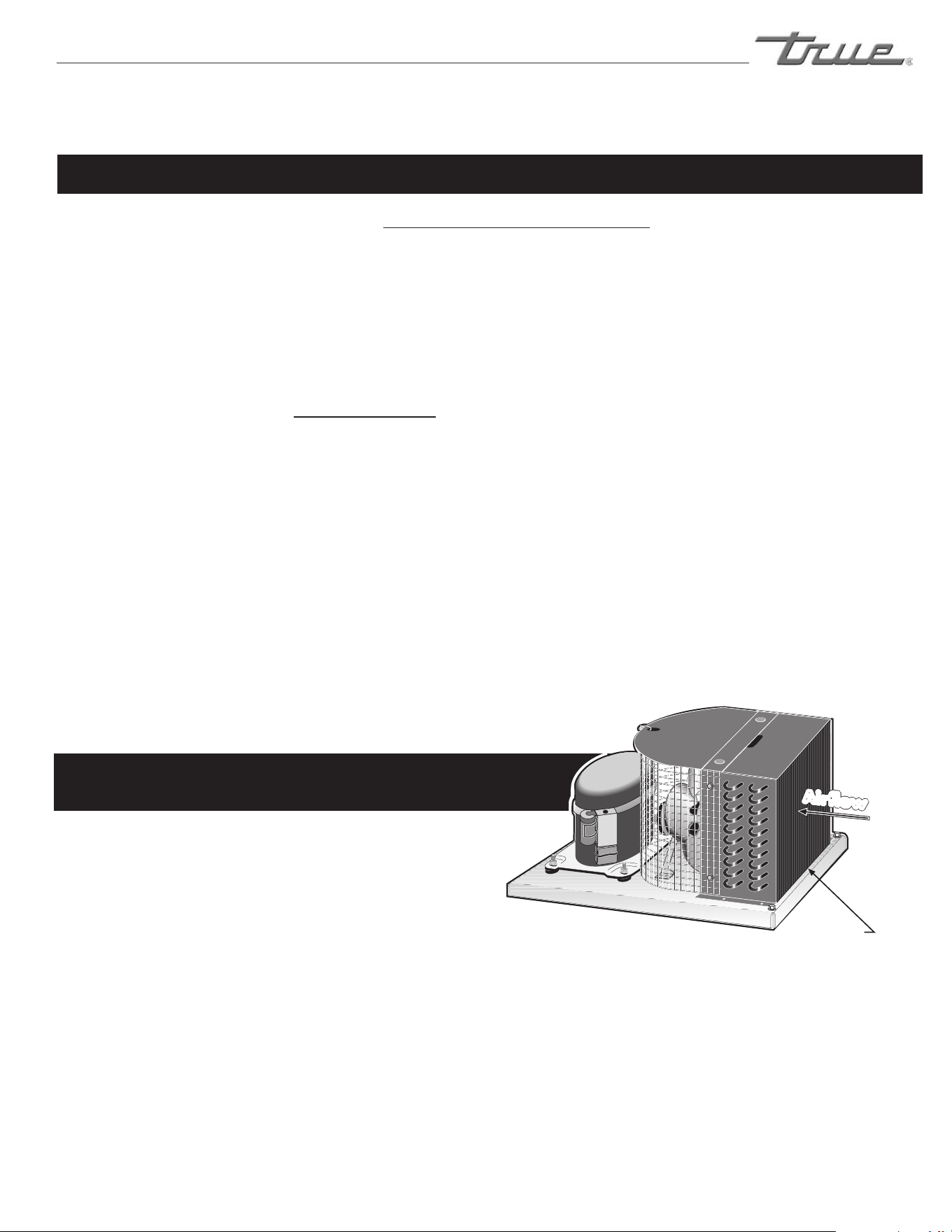
Condensers accumulate dirt and require cleaning every 30 days. Dirty condensers result in
compressor failure, product loss, and lost sales... which are not covered by warranty.
If you keep the Condenser clean you will minimize your service expense and lower your electrical costs. The
Condenser requires scheduled cleaning every thirty days or as needed.
Air is pulled through the Condenser continuously, along with dust, lint, grease, etc.
A dirty Condenser can result in NON-WARRANTEED part & Compressor Failures, Product Loss, and Lost Sales.
Proper cleaning involves removing dust from the Condenser. By using a soft brush, or vacuuming the Condenser
with a shop vac, or using CO2, nitrogen, or pressurized air.
If you cannot remove the dirt adequately, please call your refrigeration service company.
On most of the reach-in units the condenser is accessible in the rear of the unit. You must remove the cabinet grill
to expose the Condenser.
The Condenser looks like a group of vertical fins. You need to be able to see through the condenser for the unit to
function at maximum capacity. Do not place filter material in front of condensing coil. This material blocks air-flow
to the coil similar to having a dirty coil.
THE CLEANING OF THE CONDENSER IS NOT
COVERED BY THE WARRANTY!
HOW TO CLEAN THE CONDENSER:
1. Disconnect the electrical power to the unit.
2. Remove the louvered grill.
3. Vacuum or brush the dirt, lint, or debris from the finned condenser coil.
4. If you have a significant dirt build up you can blow out the condenser with compressed air.
(CAUTION MUST BE USED to avoid eye injury. Eye protection is recommended.)
5. When finished be sure to replace the louvered grill. The grill protects the condenser.
6. Reconnect the electrical power to the unit.
If you have any questions, please call TRUE Manufacturing at 636-240-2400 or 800-325-6152 and ask for the
Service Department. Service Department Availability Monday-Friday 7:30 a.m. to 6:00 p.m. and Saturday 8:00 a.m.
to 12:00 p.m. CST.
MAINTENANCE, CARE & CLEANING
Condensing Unit
Airflow
Condenser
IMPORTANT WARRANTY INFORMATION

............ www.truemfg.com ............
True Food Service Equipment, Inc.
20
20
............ www.truemfg.com ............
MAINTENANCE, CARE & CLEANING
CAUTION: Do not use any steel wool, abrasive or chlorine based products to clean stainless steel surfaces.
StainlessSteelOpponents
Therearethreebasicthingswhichcanbreakdownyourstainlesssteel’spassivitylayerandallow
corrosiontorearitsuglyhead.
1) Scratchesfromwirebrushes,scrapers,andsteelpadsarejustafewexamplesofitemsthatcanbeabrasivetostainless
steel’ssurface.
2) Depositsleftonyourstainlesssteelcanleavespots.Youmayhavehardorsoftwaterdependingonwhatpartofthe
countryyoulivein.Hardwatercanleavespots.Hardwaterthatisheatedcanleave
depositsiflefttosittoolong.Thesedepositscancausethepassivelayertobreakdownandrustyourstainlesssteel.
Alldepositsleftfromfoodpreporserviceshouldberemovedassoonaspossible.
3) Chloridesarepresentintablesalt,food,andwater.Householdandindustrialcleanersaretheworsttypeofchlorides
touse.
8stepsthatcanhelppreventrustonstainlesssteel:
1. Usingthecorrectcleaningtools
Usenon-abrasivetoolswhencleaningyourstainlesssteelproducts.Thestainlesssteel’spassivelayerwillnotbeharmed
bysoftclothsandplasticscouringpads.Step2tellsyouhowtofindthepolishingmarks.
2. Cleaningalongthepolishlines
Polishinglinesor“grain”arevisibleonsomestainlesssteels.Alwaysscrubparalleltovisiblelinesonsomestainlesssteels.
Useaplasticscouringpadorsoftclothwhenyoucannotseethegrain.
3. Usealkaline,alkalinechlorinatedornon-chloridecontainingcleaners
Whilemanytraditionalcleanersareloadedwithchlorides,theindustryisprovidinganeverincreasingchoiceofnon-
chloridecleaners.Ifyouarenotsureofyourcleaner’schloridecontentcontactyourcleanersupplier.Iftheytellyouthat
yourpresentcleanercontainschlorides,askiftheyhaveanalternative.Avoidcleanerscontainingquaternarysaltsasthey
canattackstainlesssteel,causingpittingandrusting.
4. WaterTreatment
Toreducedeposits,softenthehardwaterwhenpossible.Installationofcertainfilterscanremovecorrosiveand
distastefulelements.Saltsinaproperlymaintainedwatersoftenercanbetoyouradvantage.Contactatreatment
specialistifyouarenotsureoftheproperwatertreatment.
5. Maintainingthecleanlinessofyourfoodequipment
Usecleanersatrecommendedstrength(alkaline,alkalinechlorinatedornon-chloride).Avoidbuild-upofhardstainsby
cleaningfrequently.Whenboilingwaterwithyourstainlesssteelequipment,thesinglemostlikelycauseofdamageis
chloridesinthewater.Heatinganycleanerscontainingchlorideswillhavethesamedamagingeffects.
6. Rinse
Whenusingchlorinatedcleanersyoumustrinseandwipedryimmediately.Itisbettertowipestandingcleaningagents
andwaterassoonaspossible.Allowthestainlesssteelequipmenttoairdry.Oxygenhelpsmaintainthepassivityfilmon
stainlesssteel.
7. Hydrochloricacid(muriaticacid)shouldneverbeusedonstainlesssteel
8. Regularlyrestore/passivatestainlesssteel
STAINLESS STEEL EQUIPMENT CARE AND CLEANING

............ www.truemfg.com ............
True Food Service Equipment, Inc.
21
21
MAINTENANCE, CARE & CLEANING
Recommended cleaners for certain situations / environments of stainless steel
A)Soap,ammoniaanddetergentmedallionappliedwithaclothorspongecanbeused
forroutinecleaning.
B) Arcal20,Lac-O-NuEcoshineappliedprovidesbarrierfilmforfingerprintsandsmears.
C)Cameo,Talc,ZudFirstImpressionisappliedbyrubbinginthedirectionofthepolishedlinesfor
stubbornstainsanddiscoloring.
D)Easy-offandDe-GreaseItovenaidareexcellentforremovalsonallfinishesforgrease-fattyacids,
bloodandburnt-onfoods.
E)Anygoodcommercialdetergentcanbeappliedwithaspongeorclothtoremovegreaseandoil.
F) Benefit,SuperSheen,SheilaShinearegoodforrestoration/passivation.
NOTE:
The use of stainless steel cleaners or other such solvents is not
recommended on plastic parts. Warm soap and water will suffice.
STAINLESS STEEL EQUIPMENT CARE AND CLEANING
............ www.truemfg.com ............
True Food Service Equipment, Inc.
22
22
INSTALLATION / OPERATION INSTRUCTIONS
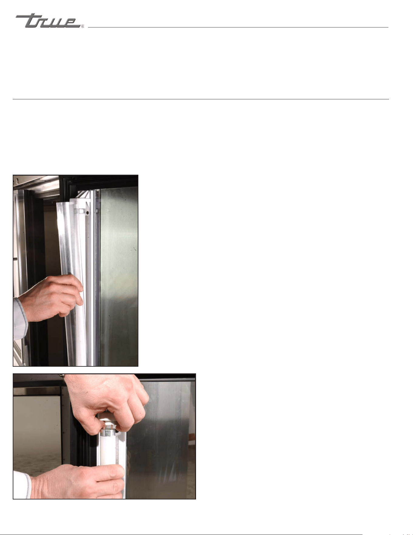
Becarefulwhenremovingthelightbulb.Please
beawareofyourlocalordinancesindisposing
oldflorescentbulbs.Thesebulbsshouldbedis-
posedinasafeandcorrectmanner.
WARNING
When replacing a light bulb make sure power to
the unit is either turned off
or unplugged.
LIGHT BULB REPLACEMENT (IDL)
INTEGRATED DOOR LIGHTING
Remove the lampshield to reveal
the bulb. Squeeze the sides of the
lampshield at the same time pull-
ing it away from the bulb.
The lamp holders are spring acti-
vated. Pull the top lamp holder
up and push the bulb down at the
same time. This will leave enough
clearance to remove the bulb.

23
23
WARRANTY INFORMATION (U.S.A & CANADA ONLY!)
T
RUE
R
EFRIGERATION
MADE IN
SINCE 1945
U.S.A.
®
THREE YEAR PARTS &LABOR WARRANTY
ADDITIONAL TWO YEAR COMPRESSOR WARRANTY
404A/134A COMPRESSOR WARRANTY
WARRANTY CLAIMS
WHAT IS NOT COVERED BY THIS WARRANTY
TRUE warrants to the original purchaser of every new TRUE refrigerated unit, the cabinet and all parts thereof, to be free from defects in
material or workmanship, under normal and proper use and maintenance service as specified by TRUE and upon proper installation and start-up in
accordance with the instruction packet supplied with each TRUE unit. TRUE’s obligation under this warranty is limited to a period of three (3) years
from the date of original installation or 39 months after shipment date from TRUE, whichever occurs first.
Any part covered under this warranty that are determined by TRUE to have been defective within three (3) years of original installation or
thirty-nine (39) months after shipment date from manufacturer, whichever occurs first, is limited to the repair or replacement, including labor charges,
of defective parts or assemblies. The labor warranty shall include standard straight time labor charges only and reasonable travel time, as determined
by TRUE.
Warranty does not cover standard wear parts which include door gaskets, incandescent bulbs or fluorescent bulbs. Warranty also does
not cover issues caused by improper installation or lack of basic preventative maintenance which includes regular cleaning of condenser coils.
In addition to the Three (3) year warranty stated above, TRUE warrants its hermetically and semi-hermetically sealed compressor to be free
from defects in both material and workmanship under normal and proper use and maintenance service for a period of two (2) additional years from the
date of original installation but not to exceed five (5) years and three (3) months after shipment from the manufacturer.
Compressors determined by TRUE to have been defective within this extended time period will, at TRUE’s option, be either repaired or
replaced with a compressor or compressor parts of similar design and capacity.
The two (2) year extended compressor warranty applies only to hermetically and semi-hermetically sealed parts of the compressor and
does not apply to any other parts or components, including, but not limited to: cabinet, paint finish, temperature control, refrigerant, metering device,
driers, motor starting equipment, fan assembly or any other electrical component, etcetera.
The two year compressor warranty detailed above will be voided if the following procedure is not carefully adhered to:
1. This system contains R404A or R134A refrigerant and polyol ester lubricant. The polyol ester lubricant has rapid moisture absorbing
qualities. If long exposure to the ambient conditions occur, the lubricant must be removed and replaced with new. For oil amounts and specifications
please call TRUE technical service department (800-325-6152). Failure to comply with recommended lubricant specification will void the compressor
warranty.
2. Drier replacement is very important and must be changed when a system is opened for servicing. A drier using XH-7 desiccant or an
exact replacement solid core drier must be used. The new drier must also be the same capacity as the drier being replaced.
3. Micron level vacuums must be achieved to insure low moisture levels in the system. 500 microns or lower must be obtained.
All claims for labor or parts must be made directly through TRUE. All claims should include: model number of the unit, the serial number of
the cabinet, proof of purchase, date of installation, and all pertinent information supporting the existence of the alleged defect.
In case of warranty compressor, the compressor model tag must be returned to TRUE along with above listed information.
Any action or breach of these warranty provisions must be commenced within one (1) year after that cause of action has occurred.
TRUE’s sole obligation under this warranty is limited to either repair or replacement of parts, subject to the additional limitations below. This
warranty neither assumes nor authorizes any person to assume obligations other than those expressly covered by this warranty.
NO CONSEQUENTIAL DAMAGES. TRUE IS NOT RESPONSIBLE FOR ECONOMIC LOSS; PROFIT LOSS; OR SPECIAL, INDIRECT, OR
CONSEQUENTIAL DAMAGES, INCLUDING WITHOUT LIMITATION, LOSSES OR DAMAGES ARISING FROM FOOD OR PRODUCT SPOILAGE CLAIMS
WHETHER OR NOT ON ACCOUNT OF REFRIGERATION FAILURE.
WARRANTY IS NOT TRANSFERABLE. This warranty is not assignable and applies only in favor of the original purchaser/user to whom
delivered. ANY SUCH ASSIGNMENT OR TRANSFER SHALL VOID THE WARRANTIES HEREIN MADE AND SHALL VOID ALL WARRANTIES, EXPRESS OR
IMPLIED, INCLUDING ANY WARRANTY OF MERCHANTABILITY OR FITNESS FOR A PARTICULAR PURPOSE.
IMPROPER USAGE. TRUE ASSUMES NO LIABILITY FOR PARTS OR LABOR COVERAGE FOR COMPONENT FAILURE OR OTHER DAMAGES
RESULTING FROM IMPROPER USAGE OR INSTALLATION OR FAILURE TO CLEAN AND/OR MAINTAIN PRODUCT AS SET FORTH IN THE WARRANTY
PACKET PROVIDED WITH THE UNIT.
RESIDENTIAL APPLICATIONS: TRUE assumes no liability for parts or labor coverage for component failure or other damages resulting from
installation in non-commercial or residential applications.
ALTERATION, NEGLECT, ABUSE, MISUSE, ACCIDENT, DAMAGE DURING TRANSIT OR INSTALLATION, FIRE, FLOOD, ACTS OF GOD. TRUE
is not responsible for the repair or replacement of any parts that TRUE determines have been subjected after the date of manufacture to alteration,
neglect, abuse, misuse, accident, damage during transit or installation, fire, flood, or act of God.
IMPROPER ELECTRICAL CONNECTIONS. TRUE IS NOT RESPONSIBLE FOR THE REPAIR OR REPLACEMENT OF FAILED OR DAMAGED
COMPONENTS RESULTING FROM INCORRECT SUPPLY VOLTAGE, THE USE OF EXTENSION CORDS, LOW VOLTAGE, OR UNSTABLE SUPPLY VOLTAGE.
NO IMPLIED WARRANTY OF MERCHANTABILITY OR FITNESS FOR A PARTICULAR PURPOSE: THERE ARE NO OTHER WARRANTIES,
EXPRESSED, IMPLIED OR STATUTORY, EXCEPT THE THREE (3) YEAR PARTS &LABOR WARRANTY AND THE ADDITIONAL TWO (2) YEAR COMPRESSOR
WARRANTY AS DESCRIBED ABOVE. THESE WARRANTIES ARE EXCLUSIVE AND IN LIEU OF ALL OTHER WARRANTIES, INCLUDING IMPLIED
WARRANTY AND MERCHANTABILITY OR FITNESS FOR A PARTICULAR PURPOSE. THERE ARE NO WARRANTIES WHICH EXTEND BEYOND THE
DESCRIPTION ON THE FACE HEREOF.
OUTSIDE U.S/CANADA.: This warranty does not apply to, and TRUE is not responsible for, any warranty claims made on products sold or
used outside the United States or Canada.
THIS WARRANTY ONLY APPLIES TO UNITS SHIPPED FROM TRUE’S MANUFACTURING FACILITIES AFTER JANUARY 1, 2013.
PRODUCT MUST BE PURCHASED IN THE COUNTRY WHERE SERVICE IS REQUESTED.