Loading ...
Loading ...
Loading ...
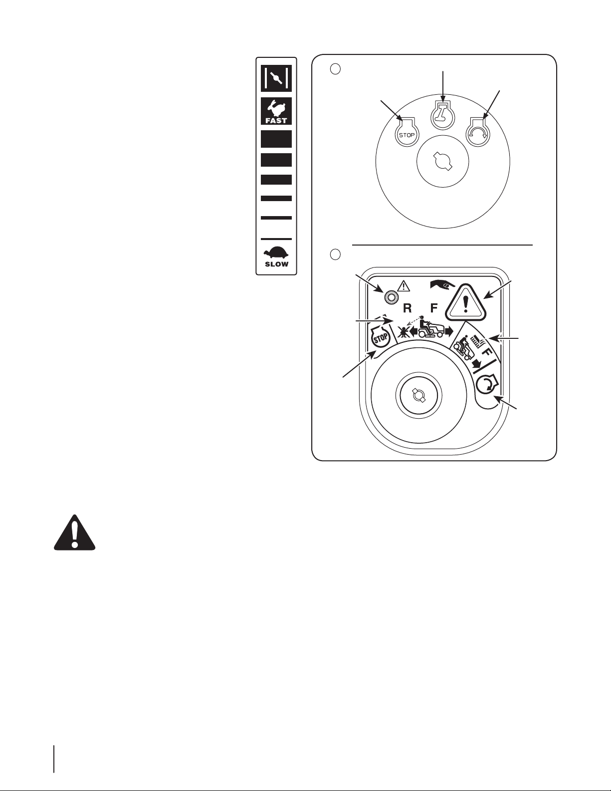
Throttle / Choke Control
The throttle control lever is located on the left side
of the tractor’s dash panel, see . This lever controls
the speed of the engine, as well as the choke when
it is pushed all the way forward. When set in a given
position, the throttle will maintain a uniform engine
speed.
IMPORTANT: When operating the tractor with the
cutting deck engaged, be certain that the throttle
lever is always in the FAST (rabbit) position.
Moving the throttle lever all the way forward
activates the engine’s choke control. Activating
the choke control closes the choke plate on the
carburetor and aids in starting the engine.
Refer to Starting The Engine in the Operation
section of this manual for detailed starting
instructions.
Ignition Switch
Your new lawn tractor will have one of the following ignition
switches. Use Figure 4-2 to identify which switch your machine
utilizes and follow these instructions for proper operation.
3-Position Ignition Switch
The ignition switch is activated to start the engine. Insert key
into the ignition switch and turn clockwise to the START position.
Release the key into the ON position once engine has fired. See
Figure 4-2A. The engine will run with the headlights on.
To stop the engine, turn the ignition key counterclockwise to the
OFF position. See Figure 4-2A.
Ignition Switch Module
To start the engine, insert the key into the ignition switch and
turn clockwise to the START position. Release the key into the
NORMAL MOWING MODE position once the engine has fired. The
headlights will be activated in the Normal (and Reverse Caution
Modes).
To stop the engine, turn the ignition key counterclockwise to the
OFF or STOP position. See Figure 4-2.
WARNING! Never leave a running machine
unattended. Always disengage PTO, move shift lever
into neutral position, set parking brake, stop engine
and remove key to prevent unintended starting.
IMPORTANT: Prior to operating the tractor, refer to both Safety
Interlock Switches and Starting The Engine in the Operation
section of this manual for detailed instructions regarding the
Ignition Switch Module and operating the tractor in REVERSE
CAUTION MODE.
Off
On/Lights
Start
A
B
Start
position
Indicator
Light
Reverse
Push
Button
Normal
Driving
Mode
Stop
position
Reverse
Caution
Mode
Position
Figure 4-2
Ammeter (if equipped)
The ammeter measures the electric current produced in
amperes.
14 Section 4— controlS and FeatureS
Loading ...
Loading ...
Loading ...