
Loading ...
Loading ...
Installation Manual of Network Camera
32
Table 1-8 Table 1 1 Description of the Camera
No.
Description
No.
Description
1
Main Unit
10
STATUS Indicator LED
2
Mounting Rail
11
LINK Indicator LED
3
Block-Shaped Sensor Unit
12
Audio Interface
4
Cover
13
RJ-12 Interface
5
Straight Mounting Bracket
14
Micro SD Card Slot
6
Cylindrical Sensor Unit
15
RESET Button
7
RJ-12 Cable
16
Power Interface
8
Round Rail Mounting Bracket
17
PoE & Network
9
POWER Indicator LED
18
RS-232 &Alarm Interface
To reset the camera, press and hold the Reset button for at least 10 seconds when powering
on or rebooting the camera.
Table 1-9 LED Indicator
LED
Color& Status
Indicator
POWER
Solid red
On normal operation
Unlit
Power Off
STATUS
Solid green
Camera works properly
Unlit
Camera does not work properly.
LINK
Flashing amber
Network connection is functioning properly
Unlit
No network connection
6.2 Installation
6.2.1 Installation of Main Unit
Steps:
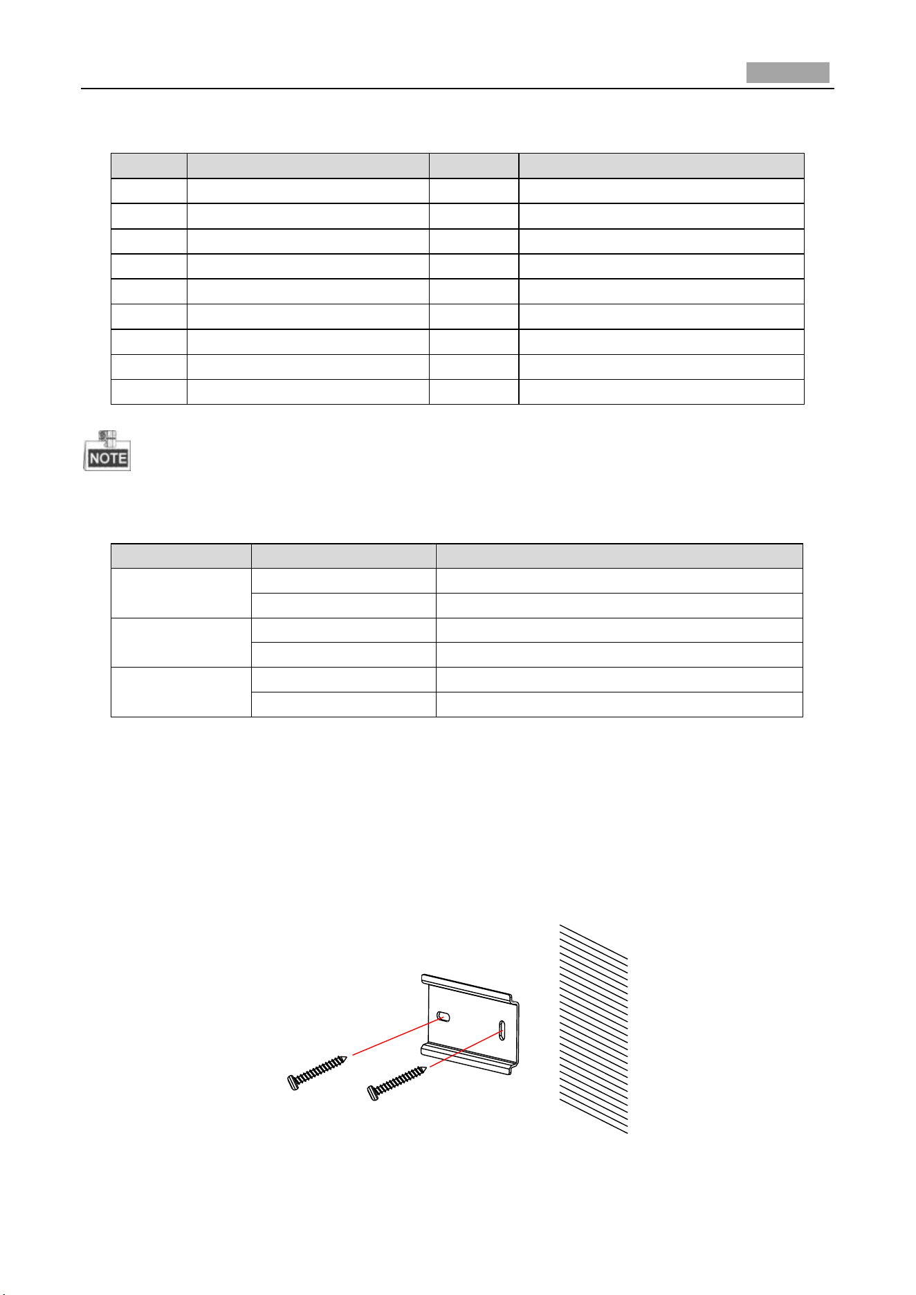
1. Fix the standard mounting rail on the mounting surface. As shown in Figure 2-1.
Figure 6-3 Fix the Standard Mounting Rail
Loading ...
Loading ...
Loading ...