HDM67G8CCB/UKHDM67G8CCB/UKHDM67G8CCB/UK

EN
ENGLISH
Health and Safety guide
Installation guide
Quick guide
2
EN
SAFETY INSTRUCTIONS
IMPORTANT TO BE READ AND OBSERVED
These instructions are valid if the country
symbol appears on the appliance. If the
symbol does not appear on the appliance, it is
necessarytoreferto theinstructionsforinstallation
which should provide the necessary instructions
concerning modification of the appliance to the
conditions of use of the country.
CAUTION: Use of the gas cooking appliance
results in the production of heat, moisture and
products of combustion in the room in which
it is installed. Ensure that the kitchen is well
ventilated, especially when the appliance is in
use: keep natural ventilation holes open or
install a mechanical ventilation device(mechanical
extractor hood). Prolonged intensive use of the
appliance may call for additional ventilation, such
asopeningawindow,ormoreeffectiveventilation,
for example increasing the level of mechanical
ventilation (if possible), to safely remove the
products of combustion to outside (external)
air whilst also providing room air changes with
additional ventilation. Consult a professional
before installation of additional ventilation.
Failure to follow the information in this manual
exactly may cause a fire or explosion, resulting in
property damage or personal injury.
Before using the appliance, read these safety
instructions. Keep them nearby for future
reference.
This appliance shall be installed in accordance
with the regulations in force and only used in a
well ventilated space. Read the instructions before
installing or using this appliance.
If the burner flames are accidentally blown
out, turn the control knob of the burner to the off
position and do not try to relight it for at least 1
minute.
These instructions and the appliance itself provide
important safety warnings, to be observed at all
times. The manufacturer declines any liability for
failure to observe these safety instructions, for
inappropriate use of the appliance or incorrect
setting of controls.
WARNING: If the hob surface is cracked, do not
use the appliance – risk of electric shock.
WARNING: Danger of fire: Do not store items
on the cooking surfaces.
CAUTION: The cooking process has to be
supervised. A short cooking process has to be
supervised continuously.
WARNING: Leaving the hob unattended when
cooking with fat or oil can be dangerous – risk of
fire. NEVER try to extinguish a fire with water, but
switch off the appliance and then cover the flames
e.g. with a lid or a fire blanket.
Donot usethe hobas awork surfaceor support.
Keep clothes or other flammable materials away
from the appliance, until all the components have
cooled down completely – risk of fire.
Very young children (0-3 years) should be kept
away from the appliance. Young children (3-8
years) should be kept away from the appliance
unless continuously supervised. Children from 8
years old and above and persons with reduced
physical, sensory or mental capabilities or lack of
experience and knowledge can use this appliance
only if they are supervised or have been given
instructions on safe use and understand the
hazards involved. Children must not play with the
appliance. Cleaning and user maintenance must
notbecarried outby childrenwithoutsupervision.
CAUTION: In case of hotplate glass breakage:
shut immediately off all burners and any electrical
heating element and isolate the appliance from
the power supply; do not touch the appliance
surface; do not use the appliance.
The glass lid can break in if it is heated up.
Turn off all the burners and the electric
plates before closing the lid. Do not shut
down lid when burner alight.
WARNING: The appliance and its accessible
parts become hot during use. Careshould be taken
to avoid touching heating elements. Children less
than 8 years of age must be kept away unless
continuously supervised.
Never leave the appliance unattended during
use. If the appliance is suitable for probe usage,
only use a temperature probe recommended for
this oven - risk of fire.
Keep clothes or other flammable materials
away from the appliance, until all the components
have cooled down completely - risk of fire. Always
be vigilant when cooking foods rich in fat, oil or
when adding alcoholic beverages - risk of fire. Use
oven gloves to remove pans and accessories. At
the end of cooking, open the door with caution,
allowing hot air or steam to escape gradually
before accessing the cavity - risk of burns. Do not
obstruct hot air vents at the front of the oven - risk
of fire.
Exercise caution when the oven door is in the
open or down position, to avoid hitting the door.
The food must not be left in or on the product
for more than one hour before or after cooking.
WARNING: Escaping gas can ignite. The device
shall not be operated for more 15s. If after 15s the
burner has not lit, stop operating the device and
open the compartment door and/or wait at least
1 min before attempting a further ignition of the
burner.
3
PERMITTED USE
CAUTION: The appliance is not intended to
be operated by means of an external switching
device, such as a timer, or separate remote
controlled system.
This appliance is intended to be used in
household and similar applications such as: staff
kitchen areas in shops, offices and other working
environments; farm houses; by clients in hotels,
motels, bed & breakfast and other residential
environments.
CAUTION:Thisappliance isfor cookingpurpose
only. It shall not be used for other purposes, for
example room heating.
This appliance is not for professional use. Do
not use the appliance outdoors.
Do not store explosive or flammable
substances (e.g. gasoline or aerosol cans) inside or
near the appliance - risk of fire.
Use pots and pans with bottoms the same
width as that of the burners or slightly larger (see
specific table). Make sure pots on the grates do
not protrude beyond the edge of the hob.
Improper use of the grids can result in damage
to the hob: do not position the grids upside down
or slide them across the hob.
Do not let the burner flame extend beyond the edge of the pan.
Do not use: Cast iron griddles, ollar stones, terracotta pots and pans.
Heat diffusers such as metal mesh, or any other types. Two burners
simultaneously for one receptacle (e.g. Fish kettle).
Should particular local conditions of the delivered gas make the ignition
of burner difficult, it is advisable to repeat the operation with the knob
turned to small flame setting.
In case of installation of a hood above the cooktop, please refer to the
hood instructions for the correct distance.
The protective rubber feet on the grids represent a chocking hazard for
young children. After removing the grids, please ensure that all the feet
are correctly fitted.
INSTALLATION
The appliance must be handled and installed
by two or more persons - risk of injury. Use
protective gloves to unpack and install - risk of
cuts.
The electrical and gas connections must
comply with local regulations.
Installation, including water supply (if any),
electrical connections and repairs must be carried
out by a qualified technician. Do not repair or
replaceany part ofthe applianceunless specifically
statedin theusermanual. Keepchildren awayfrom
the installationsite. After unpacking theappliance,
make sure that it has not been damaged during
transport. In the event of problems, contact the
dealer or your nearest After-sales Service. Once
installed, packaging waste (plastic, styrofoam
parts etc.) must be stored out of reach of children
- risk of suffocation. The appliance must be
disconnected from the power supply before any
installation operation - risk of electrical shock.
During installation, make sure the appliance does
not damage the power cable - risk of fire or
electrical shock. Only activate the appliance when
the installation has been completed.
The appliance must be installed in domestic
dwelling for typical housekeeping functions.
WARNING: Modification of the appliance and
its method of installation are essential in order to
use the appliance safely and correctly in all the
additional countries.
Use pressure regulators suitable for the gas
pressure indicated in the instructions.
The room must be equipped with an air
extraction system that expels any combustion
fumes.
The roommust alsoallow properair circulation,
as air is needed for combustion to occur normally.
The flow of air must not be less than 2 m³/h per
kW of installed power.
The air circulation system may take air directly
from the outside by means of a pipe with an inner
cross section of at least 100 cm²; the opening must
not be susceptible to blockages.
The system can also provide the air needed for
combustion indirectly, i.e. from adjacent rooms
fitted with air circulation tubes as describedabove.
However, these rooms must not be communal
rooms, bedrooms or rooms that may present a fire
hazard.
Liquid petroleum gas sinks to the floor as it
is heavier than air. Therefore, rooms containing
LPG cylinders must also be equipped with vents
to allow gas to escape in the event of a leak.
This means LPG cylinders, whether partially or
completely full, must not be installed or stored
in rooms or storage areas that are below ground
level (cellars, etc.). It is advisable to keep only the
cylinder being used in the room, positioned so
that it is not subject to heat produced by external
sources (ovens, fireplaces, stoves, etc. ) which
could raise the temperature of the cylinder above
50°C.
Should you find it difficult to turn the knobs for the burner, please
contact the After-sales Service, who can replace of the burner tap if
found to be faulty.
The openings use for the ventilation and dispersion of heat must never
be covered.
Do not remove the appliance from its
polystyrene foam base until the time of
installation.
Donotinstalltheappliancebehinda decorative
door - risk of fire.
If the range is placed on a base, it must
be leveled and fixed to the wall by the
retention chain provided, to prevent the
appliance slipping from the base.*
WARNING: In order to prevent the
appliance from tipping, the retainig device
must be installed. Refer to the instructions
for installation.*
* Available only on certain models
4
GAS CONNECTION
WARNING: Prior to installation, ensure that the
local distribution conditions (type of gas and gas
pressure) and the configuration of the appliance
are compatible.
WARNING: The adjustment conditions for this
appliance are stated on the product data plate.
Check that the pressure of the gas supply
is consistent with the values indicated in Table
“Burner and nozzle specifications”.
WARNING: This appliance is not connected
to a combustion products evacuation device. It
must be installed and connected in accordance
with current installation regulations. Particular
attention must be paid to the relevant
requirements regarding ventilation.
If the appliance is connected to liquid gas, the
regulation screw must be fastened as tightly as
possible.
IMPORTANT: When the gas cylinder or gas
container is installed, it must be properly settled
(vertical orientation).
WARNING: This operation must be perfomed
by a qualified technician.
Use only flexible or rigid metal hose for gas
connection.
Connection with a rigid pipe (copper or steel):
Connection to the gas system must be carried
out in such a way as not to place any strain of
any kind on the appliance. There is an adjustable
L-shaped pipe fitting on the appliance supply
ramp and this is fitted with a seal in order to
prevent leaks. The seal must always be replaced
after rotating the pipe fitting (the seal is provided
with the appliance). The gas supply pipe fitting is
a threaded 1/2 gas cylindrical male attachment.
Connecting a flexible jointless stainless steel
pipe to a threaded attachment:
The gas supply pipe fitting is a threaded 1/2 gas
cylindrical male attachment. These pipes must
be installed so that they are never longer than
2000 mm when fully extended. Once connection
has been made, make sure that the flexible metal
pipe does not touch any moving parts and is not
compressed. Only use pipes and seals that comply
with current national regulations.
IMPORTANT: If a stainless steel hose is used,
it must be installed so as not touch any moving
part of the furniture (e.g.drawer). It must pass
thorugh an area where there are no obstructions
and where it is possible to inspect it across its
entire length.
Theappliance should beconnectedto themain
gas supply or to a gas cylinder in compliance with
the current national regulations. Before making
the connection, make sure that the appliance is
compatible with the gas supply you wish to use.
If it is not, follow the instructions indicated in the
paragraph "Adapting to different types of gas".
After connection to the gas supply, check for
leaks with soapy water. Light up the burners and
turn the knobs from max position 1* to minimum
position 2* to check flame stability.
Connection to the gas network or the gas
cylinder may be carried out using a flexible rubber
or steel hose, in accordance with current national
legislation.
ADAPTING TO DIFFERENT TYPES OF GAS
(This operation needs to be carried out by a
qualified technician.)
In order to adapt the appliance to a type of gas
other than the type for which it was manufactured
(indicatedontheratinglabel), followthededicated
steps provided after installation drawings.
ELECTRICAL WARNINGS
IMPORTANT: Information about current and
voltage consumption is provided on the rating
plate.
The rating plate is on the front edge of the
oven (visible when the door is open).
It must be possible to disconnect the appliance
from the power supply by unplugging it if
plug is accessible, or by a multi-pole switch
installed upstream of the socket in accordance
with the wiring rules and the appliance must
be earthed in conformity with national electrical
safety standards.
The power cable must be long enough to connect the appliance,
once fitted in its housing, to the main power supply. Do not pull the
power supply cable.
Do not use extension leads, multiple sockets
or adapters. The electrical components must not
be accessible to the user after installation. Do not
use the appliance when you are wet or barefoot.
Do not operate this appliance if it has a damaged
power cable or plug, if it is not working properly,
or if it has been damaged or dropped.
If the supply cord is damaged, it must
be replaced with an identical one by the
manufacturer, its service agent or similarly
qualified persons in order to avoid a hazard -
risk of electrical shock.
If the power cable needs to be replaced,
contact an authorised service centre.
WARNING: Ensure that the appliance is
switched off before replacing the lamp to avoid
the possibility of electric shock.
Installation using a power cable plug is not
allowed unless the product is already equipped
with the one provided by the Manufacturer.
CLEANING AND MAINTENANCE
WARNING: Ensure that the appliance is
switched off and disconnected from the power
supply before performing any maintenance
operation. To avoid risk of personal injury
use protective gloves (risk of laceration) and
5
safety shoes (risk of contusion); be sure to
handle by two persons (reduce load); never use
steam cleaning equipment (risk of electric shock).
Non-professional repairs not authorised by the
manufacturer could result in a risk to health and
safety, for which the manufacturer cannot be
held liable. Any defect or damage caused from
non-professional repairs or maintenance will not
be covered by the guarantee, the terms of which
are outlined in the document delivered with the
unit.
Do not use harsh abrasive cleaners or metal
scrapers to clean the door glass since they can
scratch the surface, which may result in shattering
of the glass.
Do not use abrasive or corrosive products,
chlorine-based cleaners or pan scourers.
Make sure the appliance has cooled down
before cleaning or performing maintenance. - risk
of burns.
WARNING: Switch off the appliance before
replacing the lamp - risk of electric shock.
To avoid damaging the electric ignition device, do not use it when
the burners are not in their housing.
DISPOSAL OF PACKAGING MATERIALS
The packaging material is 100% recyclable and is marked with the
recycle symbol . The various parts of the packaging must therefore
be disposed of responsibly and in full compliance with local authority
regulations governing waste disposal.
DISPOSAL OF HOUSEHOLD APPLIANCES
This appliance is manufactured with recyclable or reusable materials.
Dispose of it in accordance with local waste disposal regulations.
For further information on the treatment, recovery and recycling
of household electrical appliances, contact your local authority, the
collection service for household waste or the store where you purchased
the appliance. This appliance is marked in compliance with European
Directive 2012/19/EU, Waste Electrical and Electronic Equipment (WEEE)
and with the Waste Electrical and Electronic Equipment regulations
2013 (as amended). By ensuring this product is disposed of correctly,
you will help prevent negative consequences for the environment and
human health. The
symbol on the product or on the accompanying
documentation indicates that it should not be treated as domestic waste
but must be taken to an appropriate collection center for the recycling
of electrical and electronic equipment.
ENERGY SAVING TIPS
Only preheat the oven if specified in the cooking table or your recipe. Use
dark lacquered or enamelled baking trays as they absorb heat better.
Use a pressure cooker to save even more energy and time.
DECLARATIONS OF CONFORMITY
This appliance meets: Ecodesign requirements of European Regulation
66/2014; Energy Labelling Regulation 65/2014; Ecodesign for Energy-
Related Products and Energy Information (Amendment) (EU Exit)
Regulations 2019, in compliance with the European standard EN 60350-
1.
This appliance meets Ecodesign requirements of European Regulation
66/2014 and The Ecodesign for Energy-Related Products and Energy
Information (Amendment) (EU Exit) Regulations 2019 in compliance with
the European standard EN 60350-2.
This appliance meets Ecodesign requirements of European Regulation
66/2014 and The Ecodesign for Energy-Related Products and Energy
Information (Amendment) (EU Exit) Regulations 2019 in compliance with
the European standard EN 30-2-1.
®
6
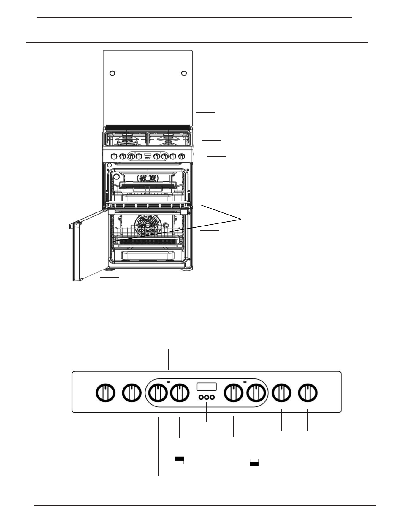
PRODUCT DESCRIPTION
7
1.
Control panel
4. Runners for accessories
(the level is indicated on the wall
of the cooking compartment)
6.
Glass cover
2.
Main oven door
Removable Inner Door Glass
5.
Gas burners
3.
CONTROL PANEL
1.
2.
3.
5.
4.
4.
6.
EN
TOP OVEN/GRILL
PILOT LIGHT
MAIN OVEN
PILOT LIGHT
ELECTRONIC
TIMER
MAIN
OVEN
THERMOSTAT
LEFT FRONT
RIGHT REAR
HOT BURNER
LEFT REAR
HOT BURNER
RIGHT FRONT
HOT BURNER
HOT BURNER
KNOB ICON
KNOB ICON
GRILL
TOP OVEN/
SELECTOR
TOP OVEN/GRILL
THERMOSTAT
8
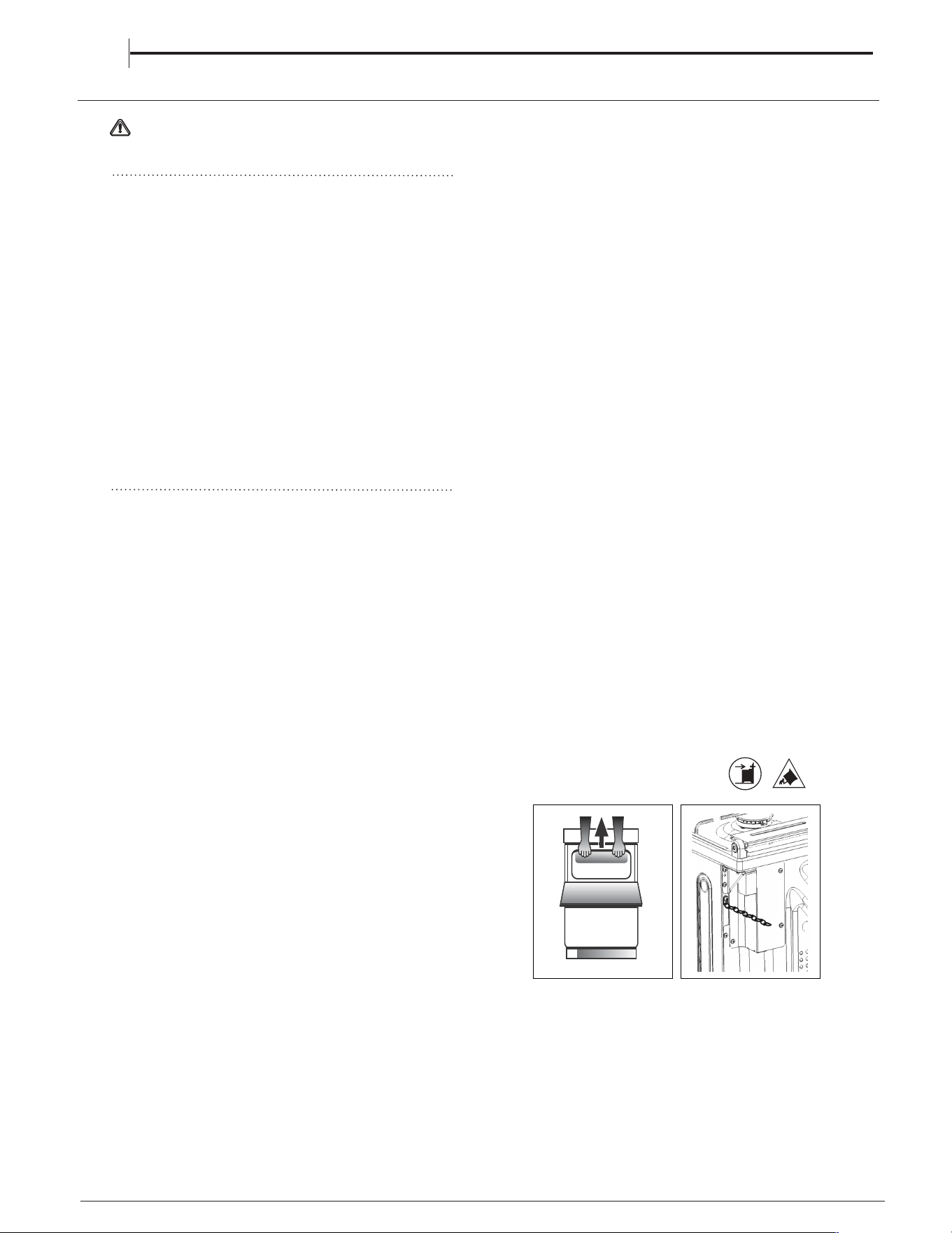
Before moving your cooker check that it is cool, and
switch off at the cooker control unit. Movement of
your cooker is most easily achieved by lifting the
front as follows:
Open the grill door sufficiently to allow a comfortable
grip on the underside front edge of the oven roof,
avoiding any grill elements. (FIG.A)
Take care in moving the cooker as it is heavy.
Take care to ensure that any floor covering is not
damaged.
The following instructions should be read by a
qualified technician to ensure that the appliance is
installed, regulated and technically serviced
correctly in compliance with current regulations.
INSTALLATION TIPS
WARNING : This operation must be perfomed
by a qualified technician
Positioning
a. The cooker should not be installed in a bed sitting
room with a volume of less than 20m
3
. If it is installed
in a room of volume less than 5m
3
an air vent of
effective area of 100cm
2
is required, if it is installed
in a room of volume between 5m
3
and 10m
3
a
supplementary airvent area of 50cm2 is required,
if the volume exceeds 10m
3
no airvent is required.
However, if the room has a door or a window which
opens directly to the outside no air vent is required
even when the volume is between 5m
3
and 10m
3
.
b. During prolonged use of the appliance you may
consider it necessary to open a window to the
outside to improve ventilation.
c. If there are other fuel burning appliances in the
same room, B.S.5440 Part 2 Current Edition, should,
be consulted to determine the requisite air vent.
The room containing the appliance must contain
an openable window or an acceptable alternative
such as an adjustable louvre or hinged panel
opening direct to outside air.
EN
This unit may be installed and used only in
permanently ventilated rooms according to the British
The following
This unit may be installed and used only in
permanently ventilated rooms according to the British
Standards Codes Of Practice: BS 5440 Part 2
requirements must be observed:
The following
Standards Codes Of Practice: BS 5440 Part 2
requirements must be observed:
Installation of the cooker
Moving the Cooker
Fig. A
Installation of the cooker
Moving the Cooker
Fig. A
For a correct installation of the cooker the following
precautions must be followed:
The height of the cooker can be adjusted by means
Adjust the feet by tilting the cooker from the side.
Then install the product into position.
NOTE: This appliance must not be fitted on a
platform.
The cooker is designed to fit between kitchen
cabinets spaced 600mm apart. The space either
side need only be sufficient to allow withdrawal of
the cooker for servicing. It can be used with
cabinets one side or both as well as in a corner
setting. It can also be used free-standing.
Adjacent side walls which project above hob level,
65mm and should be protected by heat
resistant material. Any overhanging surface or
cooker hood should not be nearer than 750mm.
a )a )
a )a )
a
) The cooker may be located in a kitchen, a
kitchen/diner or bed sitting room, but not in a
bathroom or shower room.
b )b )
b )b )
b ) The hoods must be installed according to
For a correct installation of the cooker the following
precautions must be followed:
The height of the cooker can be adjusted by means
of adjustable feet in the base of the product
Adjust the feet by tilting the cooker from the side.
Then install the product into position.
NOTE: This appliance must not be fitted on a
platform.
The cooker is designed to fit between kitchen
side need only be sufficient to allow withdrawal of
the cooker for servicing. It can be used with
cabinets one side or both as well as in a corner
setting. It can also be used free-standing.
Adjacent side walls which project above hob level,
must not be nearer to the cooker than
65mm and should be protected by heat
resistant material. Any overhanging surface or
cooker hood should not be nearer than 750mm.
a )a )
a )a )
a ) The cooker may be located in a kitchen, a
kitchen/diner or bed sitting room, but not in a
bathroom or shower room.
b )b )
b )b )
b ) The hoods must be installed according to
the requirements in the hood handbook (minimum
cabinets spaced 600mm apart. The space either
must not be nearer to the cooker than
750mm)
the requirements in the hood handbook (minimum
750mm)
dd
dd
d
))
))
) The cooker should be secured to the wall
dd
dd
d
))
))
behind via a safety chain and hook. (fig.B)
) The cooker should be secured to the wall
c )c )
c )c )
c )c )
c )c )
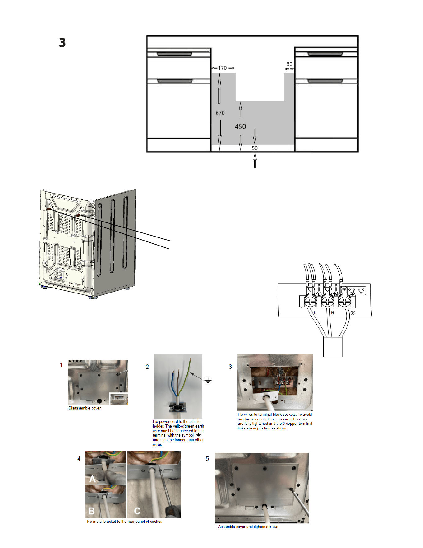
The wall behind the cooker, 50mm below and
450mm above, and the width of the cooker, must be
a noncombustible material such as ceramic wall tiles.
behind via a safety chain and hook. (fig.B)
Fig. BFig. B
(900mm - 915mm). To allow alignment with a worktop
of greater than 915mm (max 940mm), longer
adjustable feet are available as a spare part on
request.
of adjustable feet in the base of the product
(900mm - 915mm). To allow alignment with a worktop
of greater than 915mm (max 940mm), longer
adjustable feet are available as a spare part on
request.
9
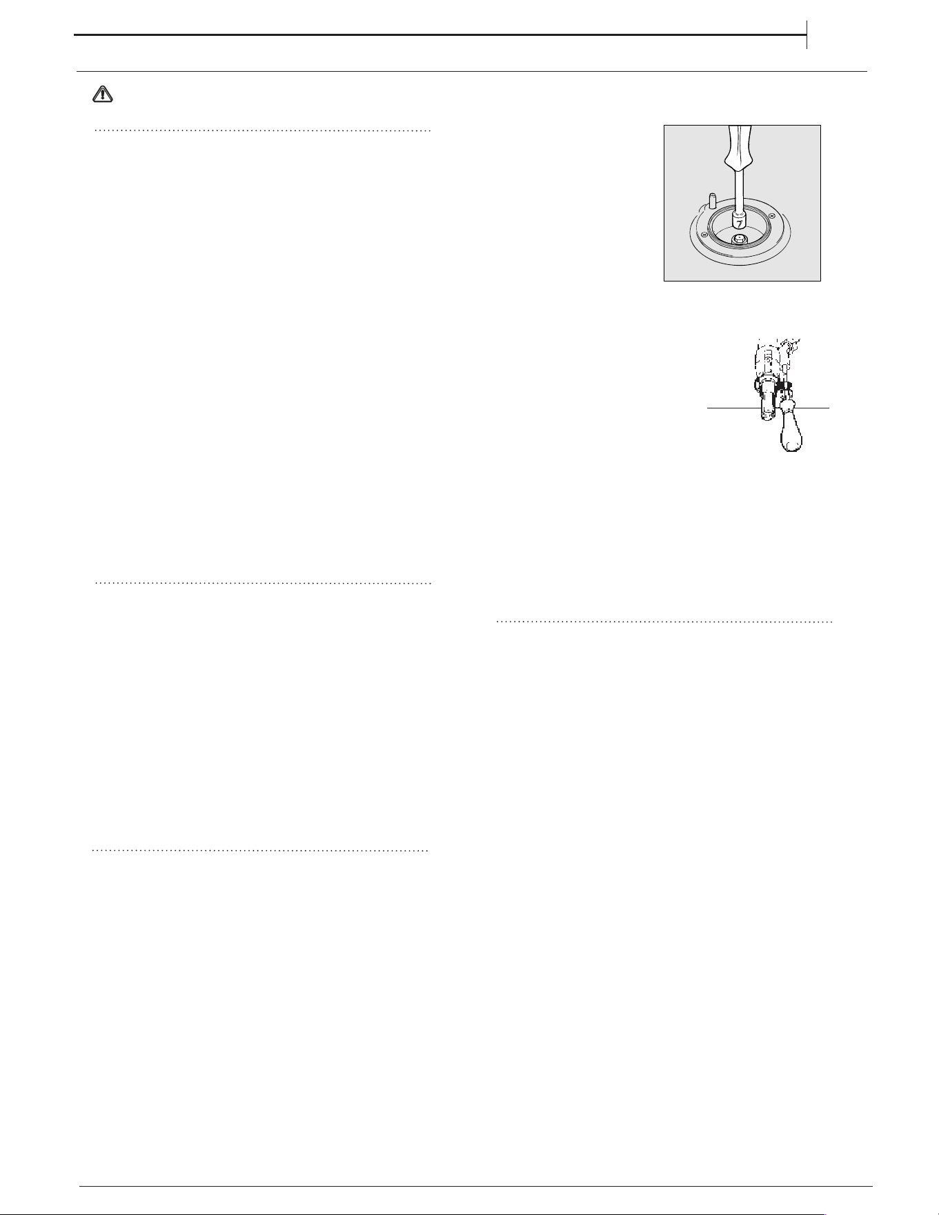
•remove the grids and slide the burners from their
housings;
•
unscrew the nozzles
using a 7 mm socket
spanner, and replace
them with nozzles for
the new type of gas
(see table 1 “Burner and
nozzle characteristics”).
•replace all the
components by
repeating the steps in
reverse order.
INSTALLATION TIPS
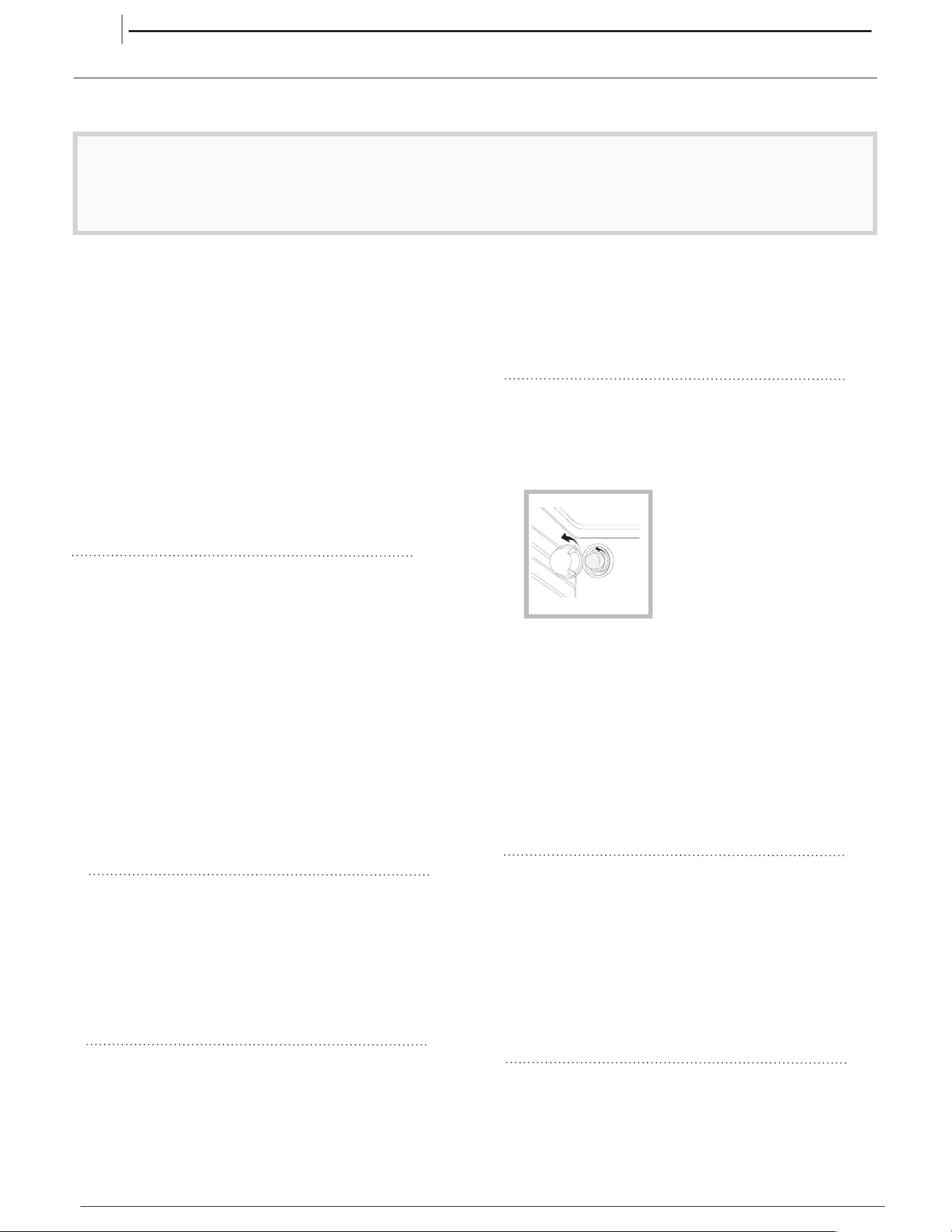
b) Minimum regulation of the hob burners:
• turn the tap to minimum;
• remove the knob and adjust
the regulation screw, which is
positioned in or next to the tap
pin, until the flame is small
but steady.
In the case of liquid gas, the regulation screw
must be adjusted to the minimum setting.
• check that the flame does not turn off when
you turn the tap quickly from high to low.
c) Regulating the primary air of the burners: The
primary air of the burners requires no regulation.
On completion of the operation, replace the old rating
sticker with one indicating the new type of gas used.
EN
The cooker should
be connected to the
gas-supply by a
gas safe registered
installer.
Connection of the appliance to the gas
mains or liquid gas must be carried out according to
the prescribed regulation in force, and only after it is
ascertained that it is adaptable to the type of gas to
be used. If not, follow the instructions indicated in
the paragraph headed “Adaptation to different gas
types”. In the case of connection to liquid gas, by
tank, use pressure regulators that conform to the
regulation in force. The gas supply must be
connected to the left of the appliance. Be sure that
the hose does not pass through the rear of the
cooker touching hot parts.
Make sure the supply pressure conforms with the
values shown in the table entitled “Caracteristics of
the burners and nozzles”.
When the cooker is installed between
cabinets (recessed), the gas connection
must be effected by an approved flexible
hose with bayonet fitting
(BS 669 or EN 1480 0). The gas inlet for
the cookers is a threaded G 1/2 gas female
f i t t i n g .
Connecting the gas supply
To make the connection, a flexible hose should be
used corresponding to the current gas regulations
which are:
• the hose must never be at any point in its
lenght in contact with the “hot” parts
of the cooker;
• the hose must never be longer than 1,5 metre;
• the hose must not be subject to any tension
or torsional stress and it must not have any
excessively narrow curves or bottlenecks;
• the hose must be easy to inspect along its
entire length to check its condition;
• the hose must always be in good condition,
never attempt to repair.
Adapting the cooker to different types of gas
In order to adapt the cooker to a different type of
gas with respect to the gas for which it was
produced
follow these steps:
a) Replacing the burner nozzles on the hob:
WARNING : This operation must be perfomed
by a qualified technician
Gas connection
DAILY USE
10
FIRST TIME USE
The hotplate lid is fitted with a safety device which cuts
off the gas supply to the hotplate burners unless the lid
is fully open. Do not use the safety device as a means
of controlling the hotplate burners.
The hotplate has two high speed burners and two
simmering burners which will accommodate pans
between 100mm (4”) and 240mm (91/2”) diameter. All
pans should be positioned centrally over the burners.
TO USE THE HOTPLATE
1. Remove any items or spillage from the top of the
lid and then raise it to its fully open position.
2. Push in and turn the control knob of the chosen
burner anti-clockwise to the large flame symbol.
Continue to press the ignition button until the sparks
light the gas.
For the models with the electronic ignition button (
), press the button and then turn the knob.
3. Turn the control knob anti-clockwise to reduce the
heat input. Only turn the control knob between the
large flame symbol and the small flame symbol
when adjusting the setting.
4. To turn off, turn the control knob fully clockwise to
the symbol O.
Each burner is fitted with a spark ignitor for lighting the
gas. To ensure rapid lighting of the burners every time
they are used, the ignitors must be kept clean and dry.
Remove any food spillage or cleaning materials from
the ignitor using a small nylon brush such as a tooth
brush. Access to the ignitor can be achieved by lifting
off the loose burner parts carefully when the burners
are cool.
When the hotplate burner bodies and caps are
removed for cleaning, be careful not to drop any food
particles or cleaning materials into the burner bases, to
avoid the possibility of blocking the gas jets.
If aluminium based pans are used, a silvery deposit
may appear on the top edge of the pan support
fingers. See 'Cleaning and Maintenance’ section for
cleaning information.
Models with Hob Gas Burner Safety Devices to
Prevent Leaks
These models can
be identified by
the presence of
the device itself.
! Since the hob
burners are
equipped with
a safety device,
you must hold the
control knob in for about 3-7 seconds after the burner
has been lighted to allow the gas to pass until the
safety thermocouple has heated.
HOB GAS BURNER
SAFETY DEVICE
ELECTRONIC
LIGHTING DEVICE
HOTPLATE
ELECTRICAL CONNECTION
WARNING : This operation must be perfomed
by a qualified technician
WARNING - THIS APPLIANCE MUST BE EARTHED.
The cooker must be connected by a qualified electrician
to a suitable double - pole control unit with a minimum
rating of 32A and a minimum contact clearance of 3mm,
which should be fitted adjacent to (but not above) the
cooker, in accordance with IEE regulations.
The power supply cable must have these minimum
requirements: Type: H05V2V2-F and compliant with
60227 IEC 57 Section: 3x4 mm2.
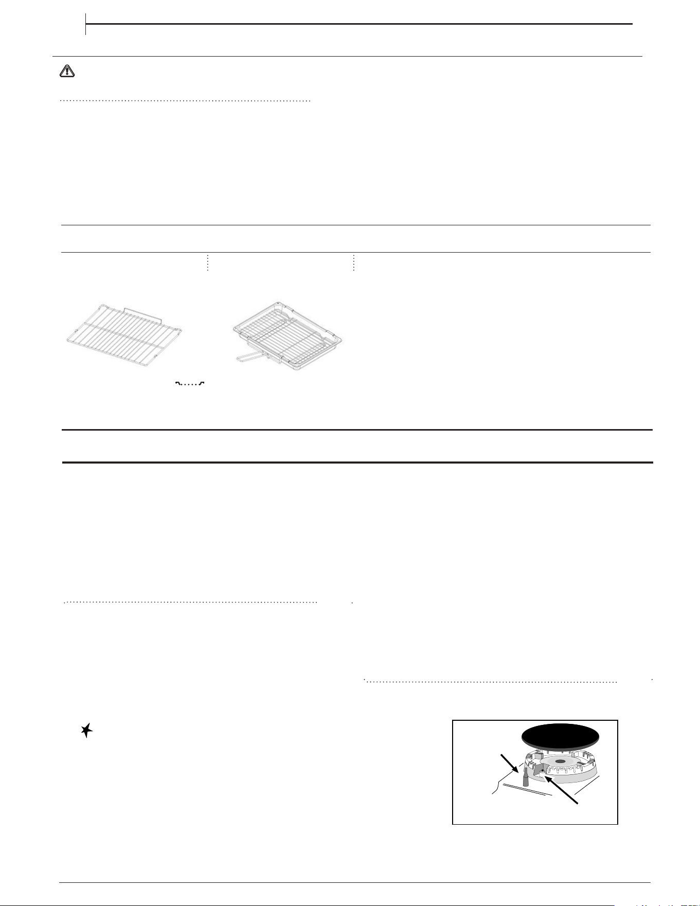
ACCESSORIES
The control unit should be easily accessible in the event of
an emergency. This appliance conforms to EN55014
regarding suppression of radio and television interference.
The cooker terminals are behind the cover at the rear
The mains cable must pass through the cable clamp and
the screws must be fully tightened. Sufficient cable should
be used to allow the cooker to be pulled out for
servicing.
Ensure that the cover is fully closed and secure afterwards.
Take care not to trap the mains cable when pushing the
cooker into its final position.
EN
The number and type of accessories may vary depending on which model
is purchased. Other accessories that are not supplied can be purchased
separately from the After-sales Service.
GRID
KIT GRILL PAN
FIRST TIME USE
To heat the oven turn the knob clockwise, selecting
the require temperature between 80°C (176°F) and
250°C (482°F) as recommended in the temperature
chart. The pilot light will immediately come on and
remain on until the oven reaches the required
temperature. This light will then automatically go off
and on during cooking as the oven thermostat
maintains the correct temperature.
MAIN OVEN
TOP OVEN
The top oven should be used to cook small
quantities of food.The oven is designed so that the
grill element operates at a reduced heat output, this
is combined with a heating element situated
underneath the floor of the oven.
To ensure even cooking of the food it is important
that cooking utensils are positioned correctly on the
oven shelf so that the element is directly above.
There are two cooking positions, the shelf placed on
runner 1 or 2 (from the base), do not use shelves
upside down.
Food/utensils must not be placed directly on the
oven floor.
There should always be at least 25mm (1in) between
the top of the food and the grill element.
Warning: Items stored in top oven will get hot when
main oven is in use.
Operation
Do not use the grill pan as a meat pan in the
top oven as air circulation will be seriously
restricted.
Top oven as a warming compartment for plates
Place the plates/dishes on the shelf, positioned on
runner 1, turn top oven control to 100°C for 10-15
minutes.Never use grill control.
It should be noted that at the end of the cooking
period there may be a momentary puff of steam
when the oven door is opened. This will disperse in
a few seconds and is a perfectly normal
characteristic of an oven with a good door seal.
Since a circulaire fan oven heats up more
quickly,and generally cooks food at a lower
temperature than a conventional oven, pre-heating is
often unnecessary.However, foods such as bread,
scones,Yorkshire pudding,do benefit from being
placed in a pre-heated oven.
The 'oven temperature charts' are a guide only,
giving approximate cooking temperatures and
times.To suit personal taste and requirements, it
may be necessary to increase or decrease
temperatures by 10°C.
Unless otherwise indicated in the charts food should
be placed in a cold oven, i.e. without pre-heating. If
food is placed in an already hot oven, the
suggested cooking time should be reduced,
depending on the type and quantity of food being
cooked.
Oven positions
Since the distribution of heat in the circulaire fan
oven is very even, most foods will cook satisfactorily
on any shelf position, but the shelves should be
evenly spaced.
The top oven rod shelf can be used in the main oven
when cooking large quantities of food.
Food or utensils should Never be placed directly
an the floor of the oven for cooking.
Never use more than 4 shelves in the oven as air
circulation will be seriously restricted.To ensure oven
circulation do not use meat pans larger than 390 x
300mm (15"x12") and baking trays no larger than
330 x 255mm (13"x 10"), these should be positioned
centrally on the oven shelf.
Food should not be placed directly on the floor of
the oven. To avoid unnecessary cleaning, rod
shelves which are not in use, should be removed
from the oven.
Temperature and time
When all four shelves are used to cook large
quantities of food for home freezing or parties, it
may be necessary to increase the cooking times
given in the temperature charts by a few minutes, to
allow for the loss of heat due to extra time taken to
load the oven, and the larger mass of food. Baking
trays should have an equal gap at either side of the
oven.
11
EN
LEVEL COOKING TIPS
1 - 2 – 3
Ideal for softening butter, gently melting chocolate in
bagnemarie, thawing small portions, creaming risotto, keeping
warm small portions of just-cooked preparation
4 - 5
Ideal for slow-cook recipes (rice,sauces,roast,fish)
using liquids (water, wine, broth), and for creaming pasta,
maintainin
g
a
g
entle boilin
g
6 - 7
Ideal for sautéing, stewing vegetables, cooking for longer
p
eriod,
p
reheat
ing
accessories, cook
ing
until cream
y
8 - 9
Ideal for browning, starting to cook, bringing liquids to the boil
quickly, frying deep-frozen products, grilling meat and fish,
maintaining a lively boil
10
Ideal for rapidly increasing the temperature of food
or for heat
ing
u
p
li
q
uids
(
water
)
When the cooker is first used an odour may be emitted,
When first using the cooker ensure that the room is well
this will cease after a period of use.
ventilated (e.g. open a window or use an extractor fan)
and that persons who may be sensitive to the odour avoid
any fumes. It is suggested that any pets be removed from
the room until the smell has ceased. This odour is due to
temporary finish on oven liners and elements and also any
moisture absorbed by the insulation.
While the top oven is heating up, the pilot light
will come on and remain on until the oven
reaches the required temperature. The pilot light
will automatically go on and off during cooking
as the thermostat maintains the correct temperature.
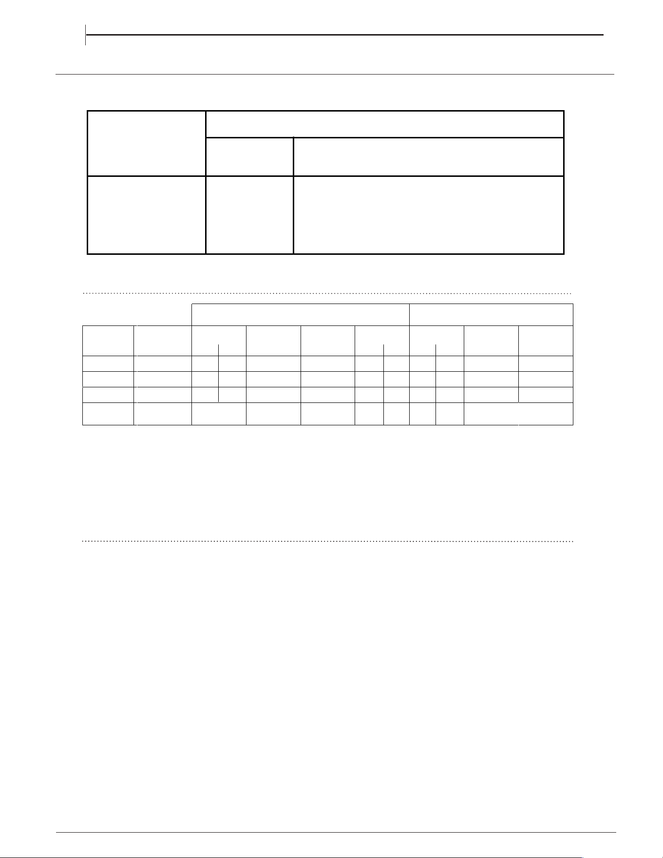
Mains frequency and voltage of the electric section and characteristics of the gas section
Model Gas section
Class
Rated power
kW (1)
II2H3+
8,00 (582 g/h - G30)
( g/h - G31)
(1) The values in g/h refer to the capacities with liquid gas (Butane, Propane).
* At 15°C and 1013 mbar - dry gas
** Propane P.C.S. = 50,37 MJ/Kg
*** Butane P.C.S. = 49,47 MJ/Kg
Natural P. C.S. = 37,78 MJ/m3
GAS NOZZLE TABLEGAS NOZZLE TABLE
GAS NOZZLE TABLEGAS NOZZLE TABLEGAS NOZZLE TABLE
12
HDM67G8C2CX/UK
571
EN
Table 1 Liquid Gas Natural Gas
Burner
D
i
ameter
(mm)
T
h
er
mal
Power
kW (p.c.s.*)
Nominal Reduced
ByPass
1/100
(mm)
Nozzle
1/100
(mm)
Fl
ow
*
g/h
*** **
Thermal Power
kW (p.c.s.*)
Nominal
Reduced
N
ozz
l
e
1/100
(mm)
Fl
ow
*
l/h
Triple Crown
(TC)
130
3.3 1.50
63 2x65
2
3
6
2
3
2
3.3 1.50
2
x
9
9
309
Semi Fast
(Medium)(S)
75
2
.
0
0
.
4
30 69
1
4
5
1
4
3
2.0 0.4
104
190
Auxiliary
(Small)(A)
55
1.0 0.4
30 50
73 71
1
.
0
0
.
4
78 95
Supply
Pressures
Nominal (mbar)
Minimum (mbar
)
Maximum (mb
ar)
2830 37
20 25
35 45
20
17
25
Table 1 Liquid Gas Natural Gas Table 1 Liquid Gas Natural Gas
)
The front right hob burner injector should be used as the pressure test point.
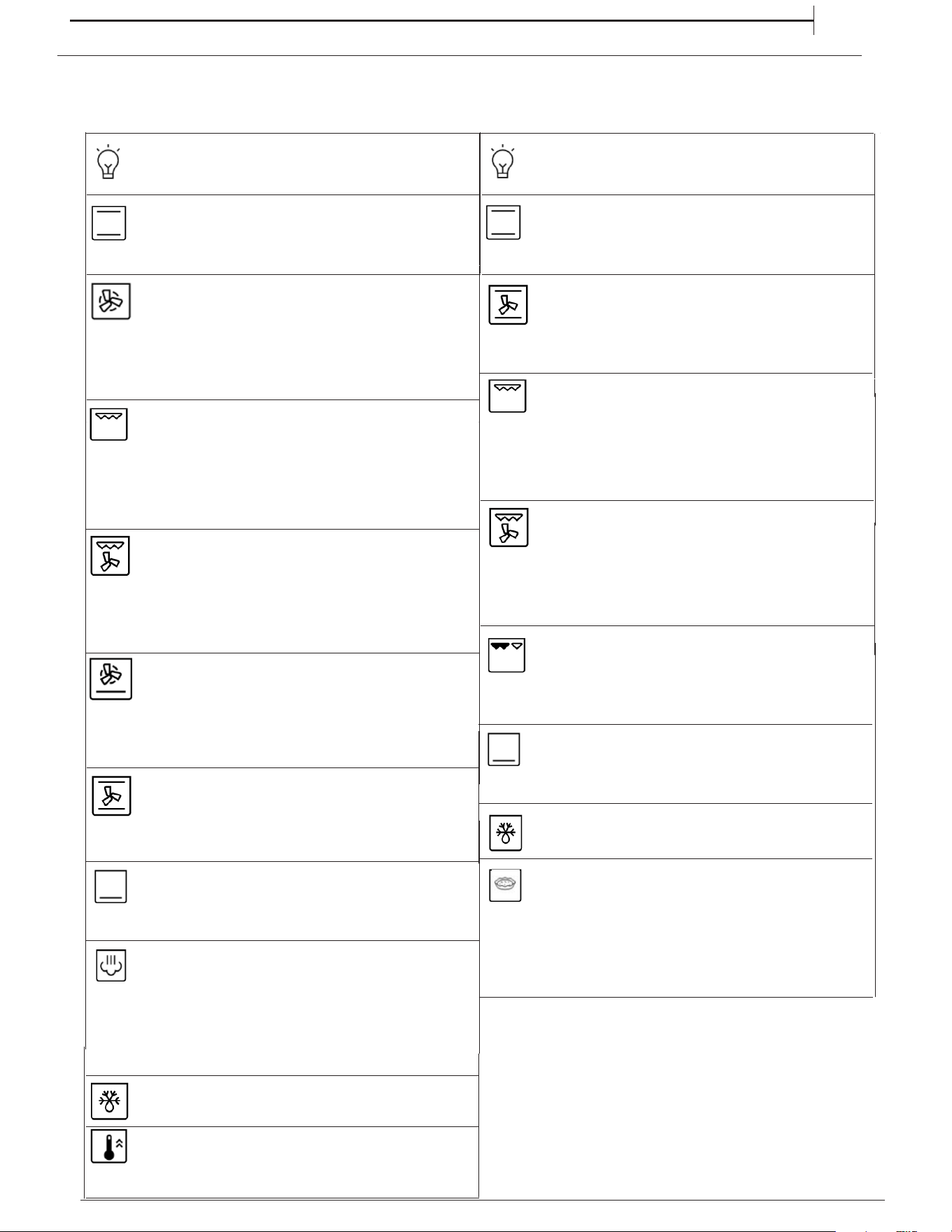
FUNCTIONS & DAILY USE
13
MAIN OVEN
CONVECTION BAKE
To cook on a maximum of two shelves at the
same time. It is a good idea to swap the position of
the baking trays halfway through cooking.
LIGHT
CONVENTIONAL
For cooking any kind of dish on one shelf only.
This function can be used to finish cooking
filled pies or to thicken soups. Use this function
for the last 10/15 minutes of cooking.
GRILL
For grilling steaks, kebabs and sausages,
cooking vegetables au gratin or toasting bread.
When grilling meat, we recommend using a drip tray
to collect the cooking juices: Position the pan on any
of the levels below the wire shelf and add 200 ml of
drinking water.
TURBO GRILL
For roasting large joints of meat (legs, roast
beef, chicken). We recommend using a drip tray to
collect the cooking juices: Position the pan on any
of the levels below the wire shelf and add 200 ml of
drinking water.
DEFROSTING
For accelerating the defrosting of food.
FORCED AIRFORCED AIR
For cooking different foods on multiple shelves (maximum
of four) at the same time. This function can be used to
cook different foods without odours being transferred from
one food to another.
To finish cooking food with a very liquid consistency
and to obtain crisp, golden bases.
Also useful for thickening sauces.
Place food on the 2nd shelf.
The oven does not have to be preheated.
BOTTOM HEATING + FAN
BOTTOM HEATING + FAN
For switching on the oven light.
STEAM
BOTTOMBOTTOM
The functions provide excellent results thanks to the
addition of steam in cooking cycles. Only when the oven
is cold, pour drinking water on the bottom of the oven and
select the specific function for your preparation. The optimal
water quantities and temperatures for each food category are
listed in the relative cooking table. Do not preheat the oven before
inserting food.
LIGHT
CONVENTIONAL
For cooking any kind of dish on one shelf only.
For switching on the oven light.
TOP OVEN
CONVECTION BAKE
To cook on a maximum of two shelves at the
same time. It is a good idea to swap the position of
the baking trays halfway through cooking.
GRILL
For grilling steaks, kebabs and sausages,
cooking vegetables au gratin or toasting bread.
When grilling meat, we recommend using a drip tray
to collect the cooking juices: Position the pan on any
of the levels below the wire shelf and add 200 ml of
drinking water.
TURBO GRILL
For roasting large joints of meat (legs, roast
beef, chicken). We recommend using a drip tray to
collect the cooking juices: Position the pan on any
of the levels below the wire shelf and add 200 ml of
drinking water.
LEFT GRILL
This function can be used to finish cooking
filled pies or to thicken soups. Use this function
for the last 10/15 minutes of cooking.
BOTTOMBOTTOM
DEFROSTING
For accelerating the defrosting of food.
STEAM
1.
SELECT A FUNCTION
For grilling small food like bacon or toasting bread.
The grill pan is placed on top of the top oven cavity
shelf. The shelf position can be adjusted to allow for grilling
different types of food.
EN
SALTY CAKE
To cook vegetable pie, quiche with liquid filling (savoury
or sweet) on a single shelf. This function delivers an even, golden,
crisp top and base,
temperature is reached.
use the 2nd shelf. Preheat the oven to the
required temperature and place the food in it when the set
To preheat the oven rapidly. At the end of preheating, select
FAST PREHEAT FAST PREHEAT
the preferred cooking function. Wait until the end of preheating
before placing food inside.
To select a function, turn the Top Oven/Grill Selection Knob to the
symbol for the function you require, then select the required
temperature by turning the Top Oven/Grill Temperature Knob.
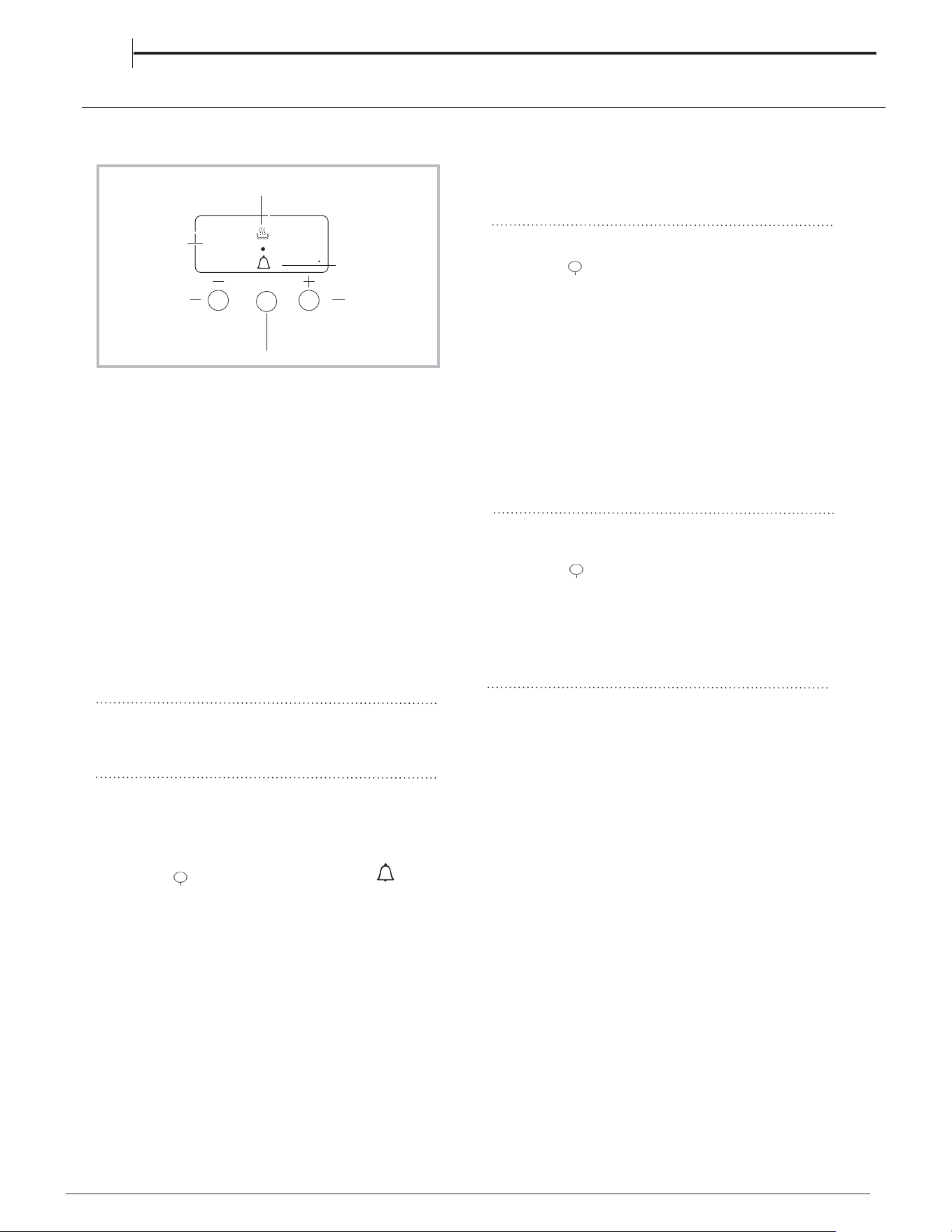
DISPLAY
MODE
button
AUTO
icon
TIMER icon
DECREASE TIME
button
INCREASE TIME
button
•• ••
Setting the clock
The clock may be set when the oven is switched off
or when it is switched on, provided that the end time of
a cooking cycle has not been programmed previously.
After the appliance has been connected to the mains,
or after a blackout, the 00:00
digits on the DISPLAY will begin to flash.
1. Press the
"+" and "-" button simultaneously
2. Use the “+” and “-” buttons to adjust the time; if you
press and hold either button, the display will scroll
through the values more quickly, making it quicker and
easier to set the desired value.
Setting the minute minder
This function does not interrupt cooking and does not
affect the oven; it is simply used to activate the buzzer
when the set amount of time has elapsed.
1. Press the button several times until the
icon
and the three digits on the display begin to flash.
2. Use the “+” and “-” buttons to set the desired time; if
you press and hold either button, the display will scroll
through the values more quickly, making it quicker and
easier to set the value.
3. Wait for 5 seconds, If you press the buttom one more time
the display will then show the time as it counts down.
When this period of time has elapsed the buzzer will be
activated.
Programming cooking
A cooking mode must be selected before
programming can take place.
Programming the cooking duration
1. Press the button several times until
icon
and the DUR digits on the DISPLAY begin to flash.
2. Use the “+” and “-” buttons to set the desired
duration; if you press and hold either button, the
display will scroll through the values more quickly,
making it quicker and easier to set the value.
3. Wait for 5 seconds, after that the icon will be visible
4. When the set time has elapsed
and the oven will stop cooking
you will hear a buzzer sounds. Press any button to stop the
buzzer.
• For example: it is 9:00 a.m. and a time of 1 hour and
15 minutes is programmed. The programme will
stop automatically at 10:15 a.m.
Cancelling a programme
To cancel a programme:
• press
the button until the icon corresponding to
the setting you wish to cancel and the digits on the
display are flashing. Press the “-” button until the
digits 00:00 appear on the display.
• Press and hold the “+” and “-” buttons; this will
cancel all the settings selected previously, including
timer settings.
on the display.
A
Changing the buzzer frequency
The buzzer signal frequency can be changed by
touching the "- " repeatedly.
Than the colon between hours and minutes is flashing.
COOKING PROCESS
icon
CLOCK MINUTE MINDER OPERATION
////
14
EN
A
A
Ensure that the correct time of day is always set
before using your cooker.
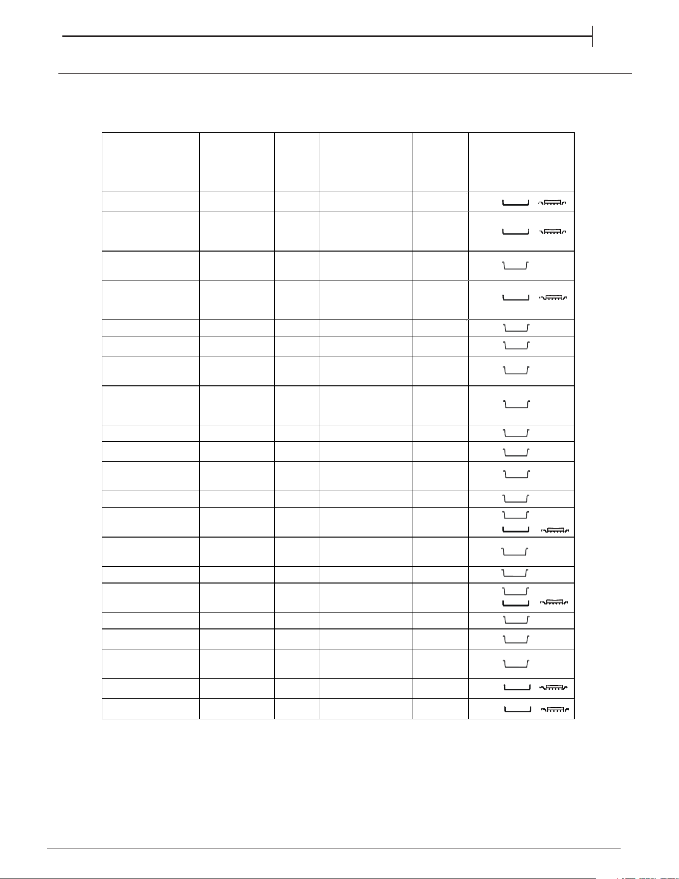
COOKING TABLE - MAIN OVEN
15
EN
RECIPE FUNCTION PREHEAT
TEMPERATURE (°C) /
POWER LEVEL
DURATION
(Min)
LEVEL (L-number) AND
ACCESSORIES
Leavened cakes /
Sponge cakes
CONVENTIONAL
YES 170 30 - 50
Leavened cakes /
Sponge cakes
FORCED AIR YES
160-170
30 - 50
Filled cake
(cheese cake, strudel,
fruit pie)
CONVENTIONAL
YES 160 - 180 40 - 60
Filled cake
(cheese cake, strudel,
fruit pie)
FORCED AIR YES 150 - 170 40 - 70
Cookies / Shortbread CONVENTIONAL
YES 140 - 150 30 - 60
Cookies / Shortbread FORCED AIR YES 140 - 150 40 - 60
Cookies / Shortbread FORCED AIR YES 140 - 150 35 - 50
Cookies / Shortbread FORCED AIR YES 140 - 150 35 - 70
Small cakes / Muffin CONVENTIONAL
YES 160 - 180 20 - 50
Small cakes / Muffin FORCED AIR YES 150 - 160 30 - 50
Small cakes / Muffin FORCED AIR YES 150 - 160 40 - 60
Choux buns CONVENTIONAL
YES 170 - 200 20 - 50
Choux buns FORCED AIR YES 170 - 200 20 - 50
Choux buns FORCED AIR YES 170 - 200 20 - 50
Meringues CONVENTIONAL
YES 80 - 100 120 - 200
Meringues FORCED AIR YES 80 - 100 120 - 200
Pizza / Bread / Focaccia
CONVENTIONAL
YES 190 - 250 15 - 50
Pizza / Bread / Focaccia
FORCED AIR YES 190 - 230 20 - 50
Pizza / Bread / Focaccia
FORCED AIR YES 190 - 230 20 - 50
Savoury pies (vegetable
pie, quiche)
CONVECTION
BAKE
YES 180 30 - 60
Savoury pies (vegetable
pie, quiche)
FORCED AIR YES 180 50 - 80
2
2/4
2
2/4
3
2/4
2/4/5
2/3/4/5
3
2/5
1/3/5
3
4
2
1/3/5
3
4
2
2
2/4
2/4/5
3
2/4
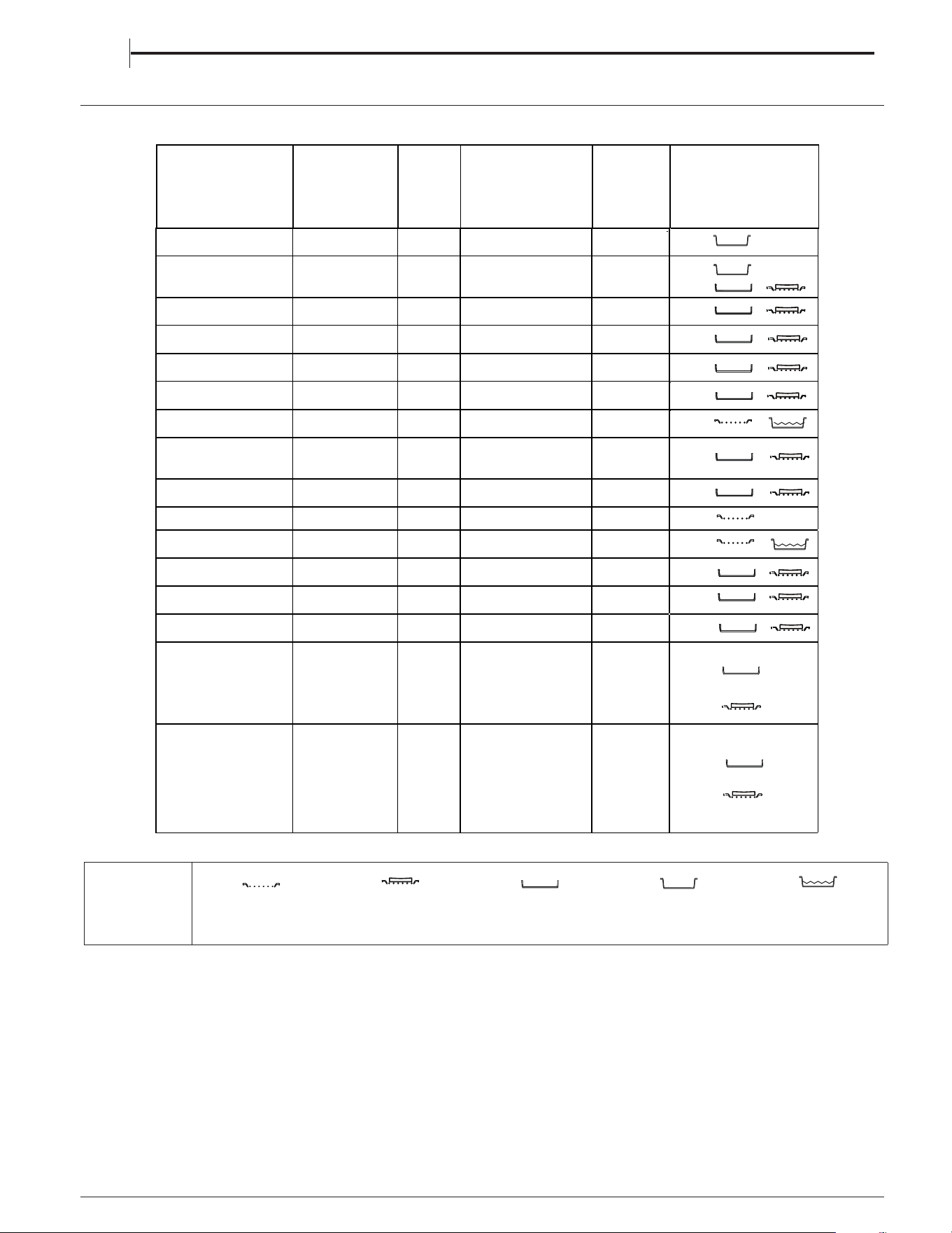
16
EN
Vols-au-vent / Puff
pastry crackers
CONVENTIONAL YES 180 - 210 15 - 40
Vols-au-vent / Puff
pastry crackers
FORCED AIR YES 180 - 210 15 - 40
Lasagne / Flans / Baked
pasta / Cannelloni
CONVENTIONAL YES 180 - 200 30 - 65
Lamb / Veal / Beef / Pork
1 kg
TURBO GRILL - 190 - MAX 40 - 90
Chicken / Rabbit / Duck
1 kg
TURBO GRILL - 230 - MAX 50 - 100
Turkey / Goose 3 kg TURBO GRILL - 160 - MAX 130 - 170
Fish fillets / Steaks GRILL - 230 - MAX 10 - 30
Stuffed vegetables
(tomatoes, courgettes,
aubergines)
TURBO GRILL - 230 - MAX 30 - 60
Vegetable gratin GRILL - 230 - MAX 10 - 30
Toast GRILL 5' MAX 1 - 2
Sausages / Kebabs /
Spare ribs / Hamburgers
GRILL - 230 - MAX 15 - 30
Roast potatoes TURBO GRILL - 230 - MAX 30 - 60
Roast potatoes TURBO GRILL - 230 - MAX 30 - 60
Leg of lamb / Shanks TURBO GRILL - 200 - MAX 50 - 100
Complete meal (Cook3):
Fruit tart
Lasagne
Roast
FORCED AIR - 180 - 190 40 - 100
Complete meal (Cook4):
Fruit tart
Lasagne
Cuts of meat
Roasted vegetables
FORCED AIR - 180 - 190 40 - 80
3
4
3
2
4
4
3
3
3
3
4
4
3
3
3
ACCESSORIES
Wire shelf
Baking dish or cake tin on
the wire shelf
Baking tray/Drip tray or
Baking dish on the wire
shelf
Drip tray / Baking tray
Drip tray / Baking tray with
00 ml of water
5
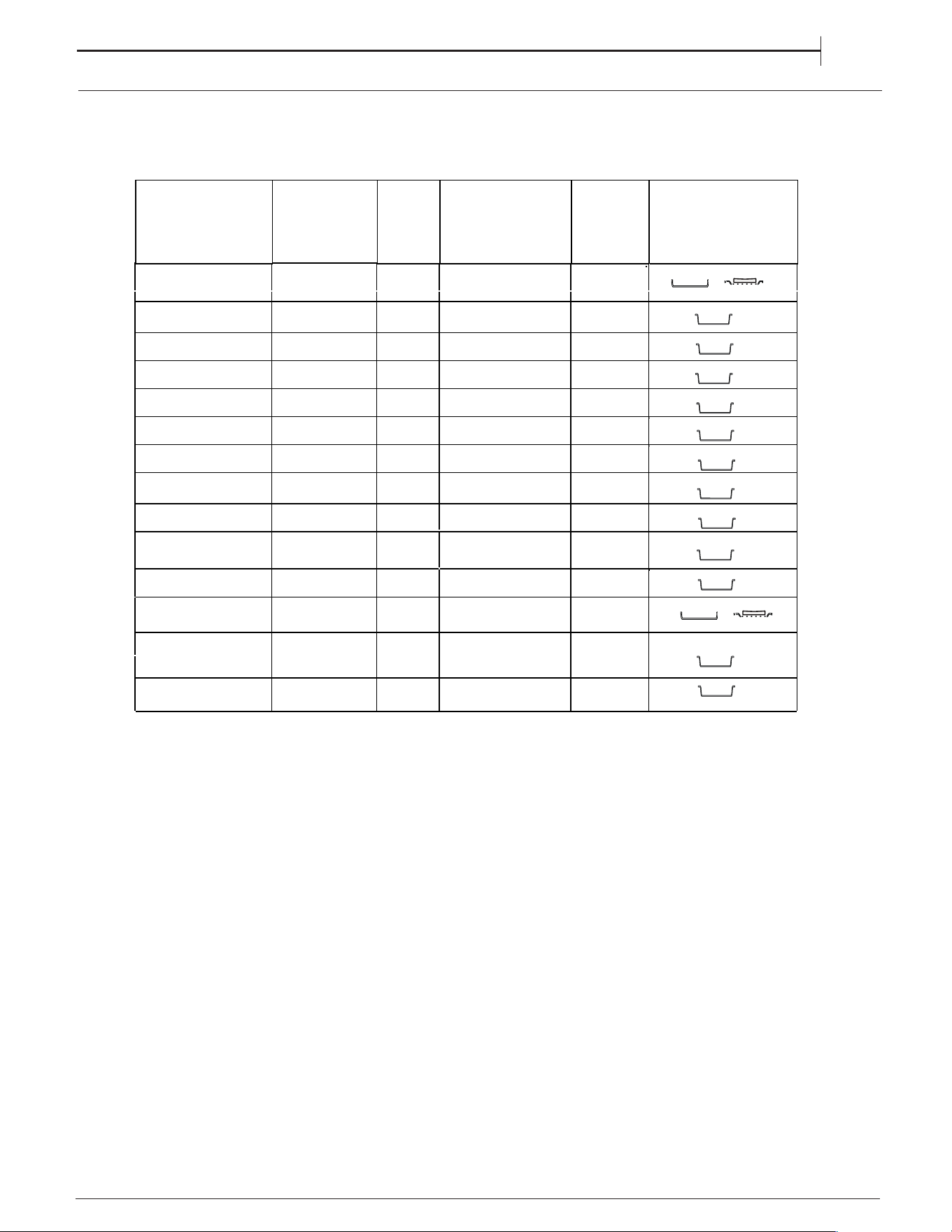
COOKING TABLE
RECIPE FUNCTION PREHEAT
TEMPERATURE (°C) /
POWER LEVEL
DURATION
(Min)
LEVEL (L-number) AND
ACCESSORIES
MAIN OVEN
1
3/5
1/2
3/5
17
EN
RECIPE FUNCTION
TEMPERATURE (°C) / DURATION
(Min)
LEVEL (L-number) AND
ACCESSORIES
COOKING TABLE
MAIN OVEN STEAM
WATER �(g)
Leavened cakes/Sponge
cakes
Shortbread/Cookies
Small cakes/Muffin
Focaccia
Bread rolls
Bread loaf
Roast Beef
Roast Beef 2Kg
Leg of lamb
Lamb / Veal / Beef /
Pork 1 kg
Chicken / Rabbit /
Duck 1 kg
Fish fillets / Steaks
Stuffed vegetables
(tomatoes,courgettes,
aubergines)
Roast potatoes
100
100
100
150
100
150
200
250
200
200
200
150
150
200
170-180
140-150
160-170
200-220
210
170-180
200
200
180-200
200
200-220
180
180-200
200-220
30-60
35-55
30-55
20-40
25-40
70-100
35-60
40-70
65-75
60-90
50-70
15-35
25-40
50-70
2
3
3
3
3
3
3
3
3
3
3
3
3
3
STEAM
STEAM
STEAM
STEAM
STEAM
STEAM
STEAM
STEAM
STEAM
STEAM
STEAM
STEAM
STEAM
STEAM
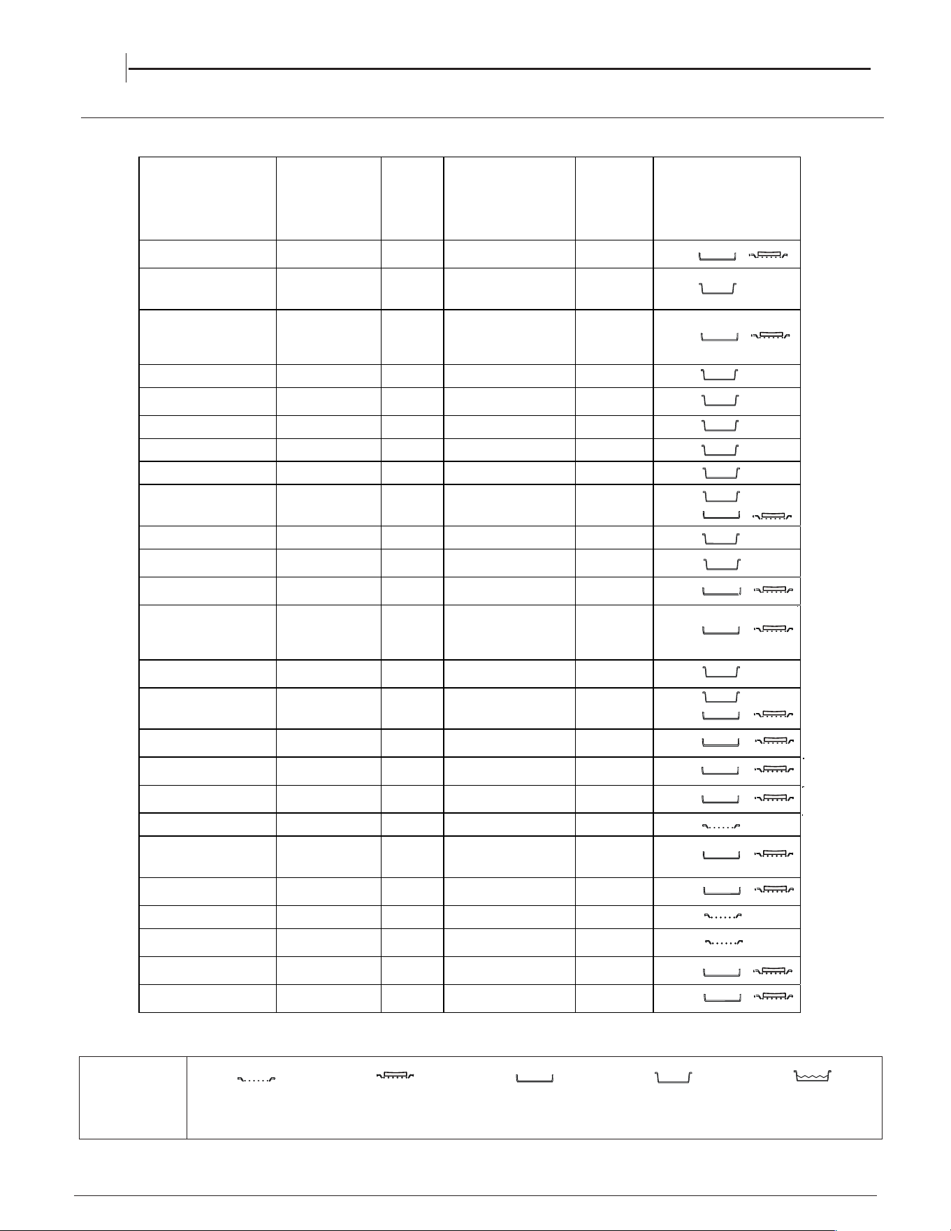
COOKING TABLE
RECIPE FUNCTION PREHEAT
TEMPERATURE (°C) /
POWER LEVEL
DURATION
(Min)
LEVEL (L-number) AND
ACCESSORIES
Leavened cakes /
Sponge cakes
CONVENTIONAL
YES 170 20 - 50
Filled cake
(cheese cake, strudel,
fruit pie)
CONVENTIONAL
YES 160 - 180 40 - 60
Filled cake
(cheese cake, strudel,
fruit pie)
CONVECTION
BAKE
YES 160 - 180 50 - 80
Cookies / Shortbread CONVENTIONAL
YES
140 - 150
20 - 50
Cookies / Shortbread
CONVECTION
BAKE YES 140 - 150
30 - 50
Small cakes / Muffin CONVENTIONAL
YES 160 - 170 20 - 50
Choux buns CONVENTIONAL
YES 170 - 200 20 - 50
Meringues CONVENTIONAL
YES 80 - 100 120 - 200
Meringues
CONVECTION
BAKE
YES 80 - 100 120 - 200
Pizza / Bread / Focaccia
CONVENTIONAL
YES 190 - 250 15 - 50
Pizza / Bread / Focaccia
CONVECTION
BAKE
YES 190 - 230 25 - 60
Savoury pies (vegetable
pie, quiche)
CONVECTION
BAKE
YES 180 30 - 50
Savoury pies (vegetable
pie, quiche)
CONVECTION
BAKE
YES 180 30 - 70
Vols-au-vent / Puff
pastry crackers
CONVENTIONAL
YES 180 - 210 15 - 40
Vols-au-vent / Puff
pastry crackers
CONVECTION
BAKE
YES 180 - 210 15 - 40
Lasagne / Flans / Baked
pasta / Cannelloni
CONVENTIONAL
YES 180 - 200 30 - 65
Lamb / Veal / Beef / Pork
1 kg
TURBO GRILL - 230 - MAX 15 - 40
Chicken / Rabbit / Duck
1 kg
TURBO GRILL - 230 - MAX 40 - 60
Fish fillets / Steaks GRILL - 230 - MAX 15 - 35
Stuffed vegetables
(tomatoes, courgettes,
aubergines)
TURBO GRILL - 230 - MAX 30 - 60
Vegetable gratin GRILL - 230 - MAX 10 - 30
Toast GRILL 5' MAX 0.5 - 1.5
Sausages / Kebabs /
Spare ribs / Hamburgers
GRILL - 230 - MAX 15 - 30
Roast potatoes TURBO GRILL - 180 - MAX 40 - 80
Leg of lamb / Shanks TURBO GRILL - 230 - MAX 30 - 80
ACCESSORIES
Wire shelf
Baking dish or cake tin on
the wire shelf
Baking tray/Drip tray or
Baking dish on the wire
shelf
Drip tray / Baking tray
Drip tray / Baking tray with
00 ml of water
5
1
2
1/3
2
1/3
2
2
2
3
1
2
1/3
1/3
2
3
1
2
2
1
2
2
2
2
2
2
2
TOP OVEN
EN
18
2
CLEANING AND MAINTENANCE
19
EN
Carefully slide the first
inner glass towards you,
taking care not to allow the
glass to fall.
Now the external glass
panel can be washed.
2. 2. 2. 2. 2.
3.3.3.3.
Ensure the glass panel is not subjected toEnsure the glass panel is not subjected to
Ensure the glass panel is not subjected toEnsure the glass panel is not subjected to
Ensure the glass panel is not subjected to
any sharp mechanical blows. any sharp mechanical blows.
any sharp mechanical blows. any sharp mechanical blows.
any sharp mechanical blows. Take particular
care not to damage the inner surface which is coated
with a heat reflective layer. After cleaning, rinse and
dry with a soft cloth. For slight soiling the inner glass
panel may be cleaned, while still warm, without
removing it from the door.
glass removed.
To reassemble the oven doors proceed with inserting
the glass panels in the reverse order, pushing gently
every panel directly into the liners, so that the warning
glass removed.glass removed.glass removed.glass removed.glass removed.
Oven must not be operated with inner door
glass removed.
sign printed on the glass is correctly legible.
4.
Oven must not be operated with inner doorOven must not be operated with inner doorOven must not be operated with inner doorOven must not be operated with inner door
Removing the retaining
Removing the retaining
bar
depress carefully
both sides of the bar.
Pull the trim up gently
until the retainer is
released.
the clips on
Open the door to .
1111
.....
Cleaning the glass door with 2 panels
TOP OVEN DOORS
30
°
TURN OFF THE MAIN SWITCH AND ENSURE THE COOKER IS COLD BEFORE CLEANING.
BEFORE SWITCHING ON AGAIN, ENSURE THAT
ALL CONTROLS ARE IN THE OFF POSITION.
Do not use steam cleaning
equipment.
Use protective gloves during all
operations.
Carry out the required
operations when the oven is cold.
Disconnect the appliance from
the power supply.
Do not use wire wool, abrasive
scourers or abrasive/corrosive
cleaning agents, as these could
damage the surfaces of the
appliance.
CLEANING AND MAINTENANCE
Disconnect the appliance from the power supply.
CLEANING THE HOB SURFACE
warm water and neutral solution.
Stainless steel surfaces may be stained by calcareous
water or aggressive detergents if left in contact for too long.
(water, sauce, coee, etc.) should be wiped
Clean with warm water and neutral detergent, and then dry
a soft cloth or chamois. Remove baked-on dirt with specic
stainless steel surfaces.
NOTE: clean stainless steel only with soft cloth or sponge.
Do not use abrasive or corrosive products, chlorine-based
or pan scourers.
Do not use steam cleaning appliances.
Do not use ammable products.
Do not leave acid or alkaline substances, such as vinegar,
mustard, salt, sugar or lemon juice on the hob.
CLEANING THE HOB PARTS
Clean glass and enamelled parts only with soft cloth or sponge.
Grids, burner caps and burners can be removed to be cleaned.
Clean them by hand with warm water and non-abrasive
detergent removing any food residues and checking that
openings is clogged.
Rinse and dry.
Ret burners and burner caps correctly in the respective
When replacing the grids, make sure that the panstand area is
with the burner.
Models equipped with electrical ignition plugs and safety
require thorough cleaning of the plug end in order to
ensure correct operation. Check these items frequently, and if
with a damp cloth. Any baked-on food
toothpick or needle.
NOTE: to avoid damaging the electric ignition device,
do not use it when the burners are not in their housing.
EXTERIOR SURFACES
• Clean the surfaces with a damp microfibre cloth.
If they are very dirty, add a few drops of pH-neutral
detergent. Dry them with a dry cloth.
• Do not use corrosive or abrasive detergents. If any of
these products inadvertently comes into contact with
the surfaces of the appliance, clean immediately with
a damp microfibre cloth.
INTERIOR SURFACES
• After every use, leave the oven to cool and then
clean it, preferably while it is still warm, to remove any
deposits or stains caused by food residues To dry any
condensation that has formed as a result of cooking
foods with a high water content, let the oven to cool
completely and then wipe it with a cloth or sponge.
• Clean the glass in the door with a suitable liquid
detergent.
CLEANING THE OVEN SURFACE
ACCESSORIES
Soak the accessories in a washing-up liquid solution
after use, handling them with oven gloves if they
are still hot. Food residues can be removed using a
washing-up brush or a sponge.
REPLACING THE LIGHT
1.
Disconnect the oven from the power supply.
2.
Unscrew the cover from the light, replace the bulb
and screw the cover back on the light.
(Only in some models)
3.
Reconnect the oven to the power supply.
Note: Use 40 W/230 V type
The bulb used in the product is specically designed for
domestic appliances and is not suitable for general room
lighting within the home (EC Regulation 244/2009).
G9
Note: Use 40 W/230 V type
Light bulbs are available from our After-sales Service.
- Do not handle bulbs with your bare hands as your
ngerprints could damage them. Do not use the oven until
the light cover has been retted.
The bulb used in the product is specically designed for The bulb used in the product is specically designed for The bulb used in the product is specically designed for
domestic appliances and is not suitable for general room
lighting within the home (EC Regulation 244/2009).
Light bulbs are available from our After-sales Service.
- Do not handle bulbs with your bare hands as your
ngerprints could damage them. Do not use the oven until
the light cover has been retted.
CATALYTIC CLEANING
These are panels coated with a special enamel, which
is able to absorb the fat released by food as it cooks.
This enamel is quite strong, so that the various
accessories (racks, dripping pans, etc.) can slide along
them without damaging them. White marks may appear
on the surfaces; these are not a cause for concern.
Nevertheless, the following should be avoided:
-scraping the enamel with sharp objects (a knife,
-using detergents or abrasive materials.
LOWER THE TOP HEATING ELEMENT
The top heating element of the grill can be lowered
to clean the upper panel of the oven: xtract the heating
E
element from its seating, then lower it. To return the
heating element to its position, lift it up, pull it slightly
towards you and make sure that the tab support is in its
proper seating.
All the enamelled and glass parts should be cleaned with
Any od spills
away beore they dry.
for
of the burner
aligned
device
necessary, clean them
should be removed with a
fo
with
cleaners
cleaners
none
housings.
for example)
20
EN
This product contains a light source of energy
efficiency class G
WWW
A complete product specification, including the energy efficiency ratings for this oven, can be read and
Problem Possible cause Solution
The oven or the burner will not
switch on.
Power cut.
Disconnection from the
mains electricity.
Check for the presence of mains electrical power
and whether the oven is connected to the
electricity supply.
Wait at least one minute, then try to switch the
oven on again and see if the problem persists.
Gas supply interrupted. Check that the gas tap upstream of the oven is
open or that the liquid gas cylinder (if being used)
is not empty.
Switch-on procedure carried
out incorrectly.
Wait at least one minute and then repeat the steps
described in the “Daily use” section.
In the event of problems, turn the adjustment knob back to the position and open the oven door.
TROUBLESHOOTING
HOW TO READ THE COOKING TABLE
The table indicates the best function to use with
certain types of food cooked on a single shelf.
Cooking times start from the moment food is placed
in the oven, excluding pre-heating (where required).
Cooking temperatures and times are purely for
guidance and will depend on the amount of food and
type of accessory used. Use the lowest recommended
settings to begin with and, if the food is not cooked
enough, then switch to higher settings. Use the
accessories supplied and preferably dark-coloured
metal cake tins and baking trays. You can also use
Pyrex pans and accessories or ones made from china,
but bear in mind that cooking times will be slightly
longer. For best results, follow the recommendations
in the cooking table carefully when selecting which
of the supplied accessories to place on which of the
shelves.
USEFUL TIPS
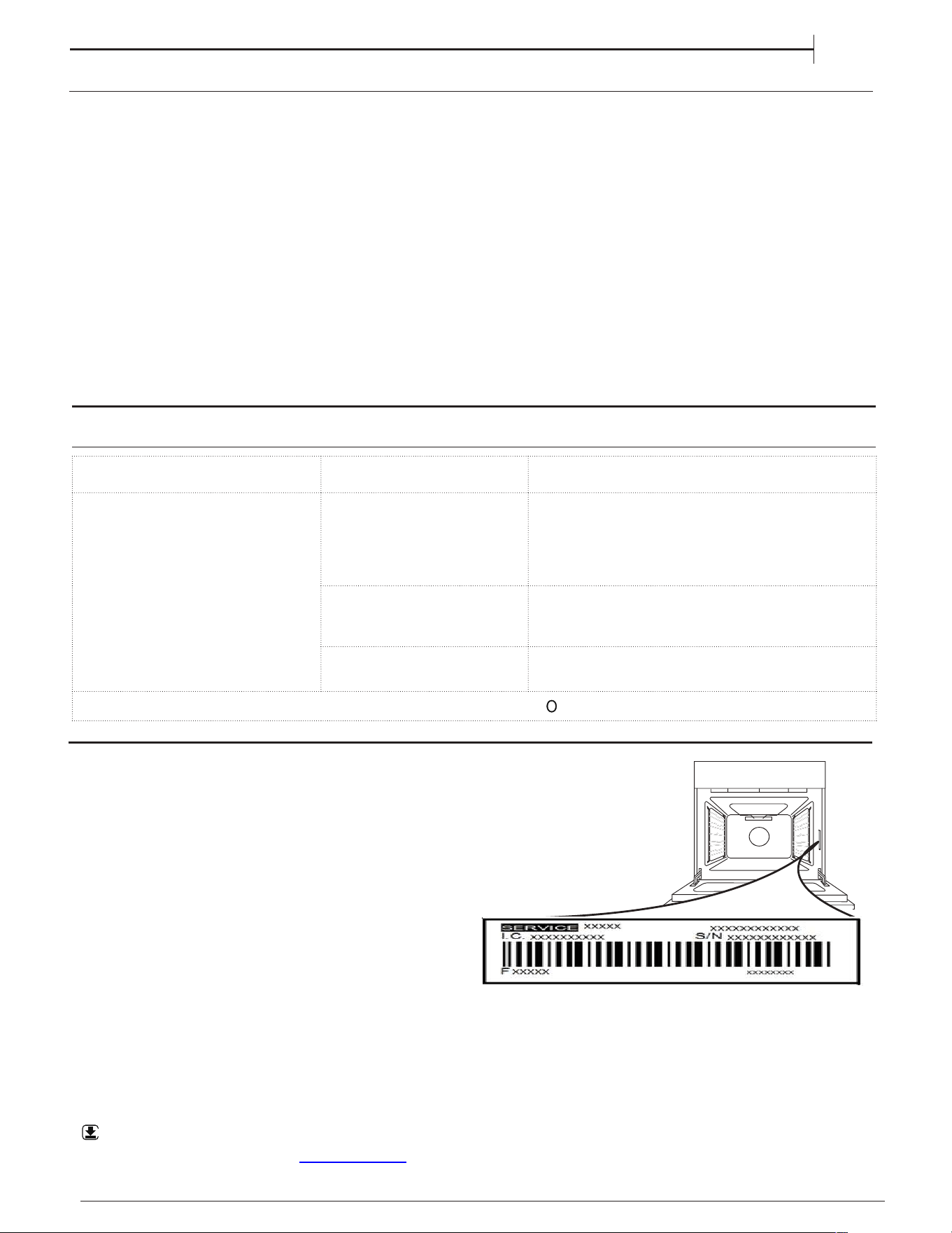
AFTER-SALES SERVICE
To receive assistance, call the number given on the
warranty leaflet enclosed with the product or follow
the instructions on our website. Be prepared to
provide:
•
a brief description of the problem;
•
the exact model type of your product;
•
the assistance code (the number following the word
SERVICE on the identification plate attached to the
product, which can be seen on the inside edge when
the oven door is open);
•
your full address;
•
a contact telephone number.
Please note: If repairs are required, contact an
authorised service centre that is guaranteed to use
original spare parts and perform repairs correctly.
Please refer to the enclosed warranty leaflet for more
information on the warranty.
downloaded from our website
docs.hotpoint.eu
21
EN
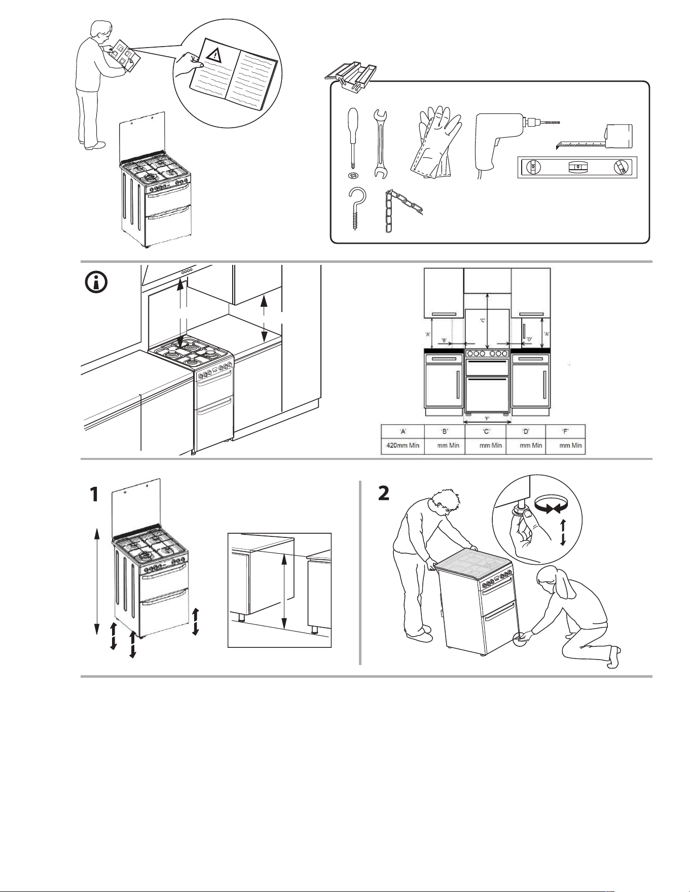
17mm - 0,67inch
max. 15 mm
Min. 420 mm
Min. 750 mm
65
600
750
65
22
23
Brown
(red)
Blue
(black)
Earth
Connecting to gas supply
Position the gas connection point such that it is located within the shaded area,
and the hose also hangs naturally within the shaded area.
Hot parts
Installation area
There are 2 spacers on the rear panel of the appliance (see Fig 1)
intended to prevent the appliance trapping the flexible hose.
If the flexible hose and it's rigid pipework connections are recessed,
the spacers can be removed by the installer to allow the appliance to
be pushed back further in the aperture. This can only be done if the
requirements of BS 6172:2010 can still be met.�7KH�SRZ HU�VXSSO\ �
FDEOH�P XVW�KDYH�WKHVH�P LQLP XP �UHTXLUHP HQWV��7\ SH���+ � � 9 � 9� �) �
DQG�FRP SOLDQW�ZLWK��� � � � � �,( &�� � �6 HFWLRQ��� [ � �P P � �
www.hotpoint.co.uk
24
10/2024 - W20005028
XEROX FABRIANO
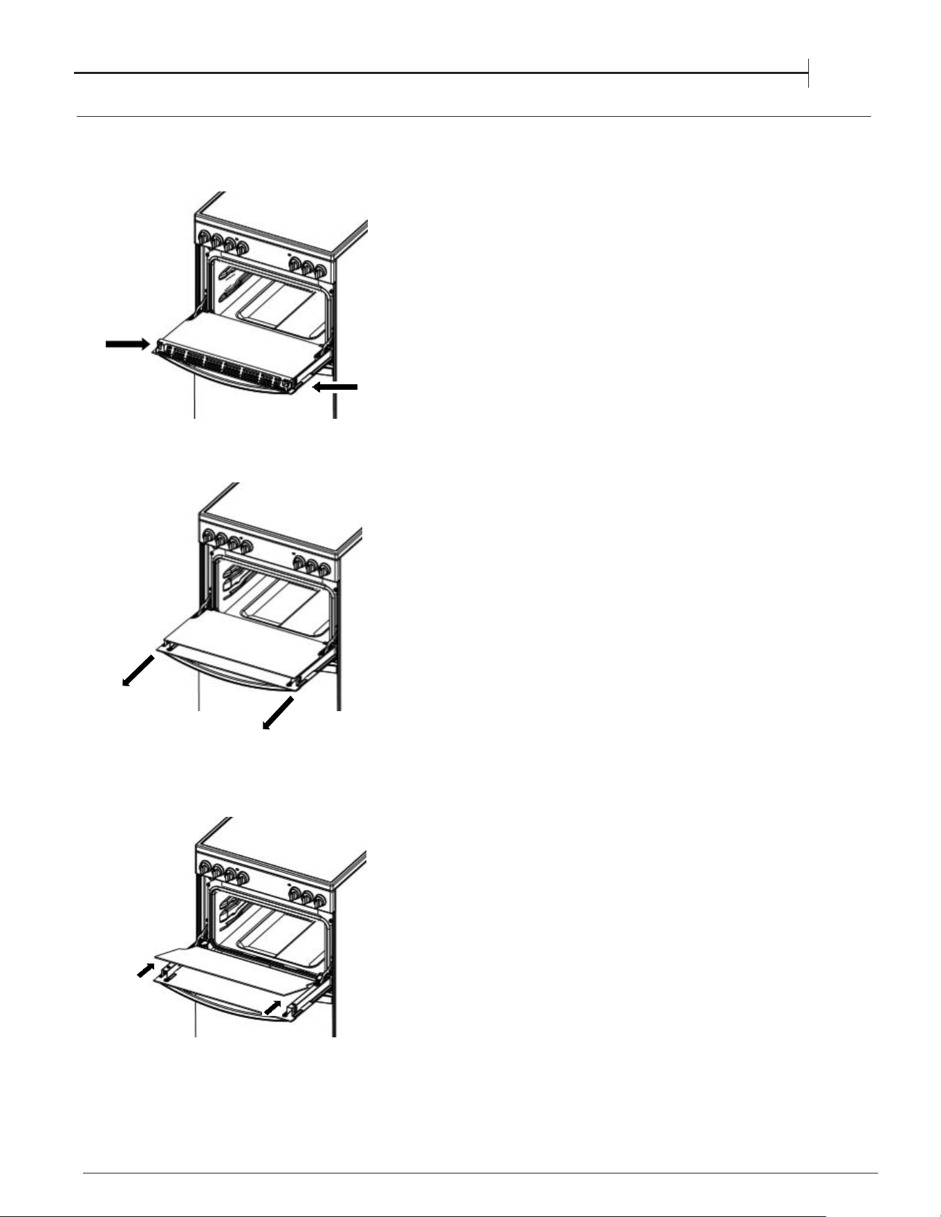
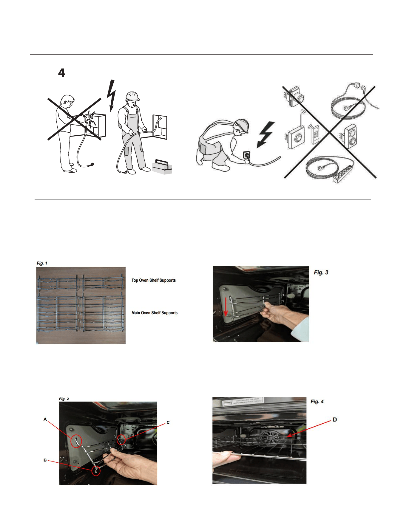
Your new cooker comes with 4 chrome shelf supports
packed in the main oven along with the shelves.
There are 2 shelf supports for the top oven and 2
for the bottom oven. See Fig. 1.
Fitting - Step 1
The top of the shelf supports engage in slots in the side
walls of the oven as in Fig. 2 below.
Note the rods ‘A’ are longer at the top than
‘B’ at the bottom, and the hooks ‘C’ are at the back of the
oven. It is important that the shelf supports
are fitted the correct way around!
Fitting - Step 2
Once engaged at the top, then push the bottom rods into
the lower slots in the oven side walls. Now allow
the shelf supports to lower slightly and engage. See Fig. 3.
This process should be repeated and all 4 shelf supports
fitted in the top and main ovens.
Fitting - Step 3
The shelves can now be fitted into the shelf supports
‘D’
that should be at the back of the oven as shown. See Fig. 4.
at the required heights. Note that there is pan guard
Your ovens are now ready to use !
Beko Europe Management Srl
Via Varesina 204,
20156 Milano, Italy