p/n: 934927
Revision B
AVR750UNC (AG-0786)
Advanced User’s Guide
Eaton Tripp Lite Series Cloud Connected UPS System

©Copyright 2023 Eaton, Raleigh, NC, USA. All rights reserved. No part of this document may be reproduced in any way without the
express written approval of Eaton.
SSaaffeettyy IInnssttrruuccttiioonnss
SAVE THESE INSTRUCTIONS.
This manual contains important instructions that should be followed during the installation and
maintenance of the UPS and batteries.
This equipment has been tested and found to comply with the limits for a Class A digital device,
pursuant to part 15 of the FCC Rules. These limits are designed to provide reasonable protection
against harmful interference when the equipment is operated in a commercial environment. This
equipment generates, uses, and can radiate radio frequency energy and, if not installed and used in
accordance with the instruction manual, may cause harmful interference to radio communications.
Operation of this equipment in a residential area is likely to cause harmful interference in which case
the user will be required to correct the interference at his own expense.
Suppliers Declaration of Conformity
Unique Identifier: EATON, AVR750UNC (AG-0786)
Responsible Party:
EATON
10000 Woodward Ave
Woodridge, IL 60517 USA
773–869–1111
tripplite.eaton.com
FCC Compliance Statement:
This device complies with Part 15 of the FCC Rules. Operation is subject to the following two
conditions:
1. This device may not cause harmful interference, and
2. this device must accept any interference received, including interference that may cause
undesired operation.
IInnnnoovvaattiioonn,, SScciieennccee aanndd EEccoonnoommiicc DDeevveellooppmmeenntt CCaannaaddaa NNoottiiccee
This Class A digital device apparatus complies with Canadian ICES-003.
CAN-ICES-003A / NMB-003A
SSppeecciiaall SSyymmbboollss
The following are examples of symbols used on the product to alert you to important information:
Danger: Dangerous voltage levels are present within the UPS. The UPS has an internal
power source (the battery). Consequently, the power outlets may be energized even if the
UPS is disconnected from the AC power source.
Important instructions that must always be followed.
CAUTION: Batteries present a risk of energy or electric shock or burn from high short circuit
currents. Observe proper precautions. Batteries may contain HIGH VOLTAGE and CORROSIVE,
TOXIC, and EXPLOSIVE substances. Do not dispose of batteries in a fire, as they may explode.
This symbol indicates that you should not discard the UPS or the UPS batteries in the trash.
This product contains sealed, lead-acid batteries and must be disposed of properly. For more
information, contact your local recycling/reuse or hazardous waste center.
Special Symbols
The following are examples of symbols used on the UPS or accessories to alert you to important
information:
RISK OF ELECTRIC SHOCK - Observe the warning associated with the risk of
electric shock symbol.
CAUTION: REFER TO OPERATOR'S MANUAL - Refer to your operator's manual for
additional information, such as important operating and maintenance
instructions.
This symbol indicates that you should not discard the UPS or the UPS batteries
in the trash. This product contains sealed, lead‐acid batteries and must be
disposed of properly. For more information, contact your local recycling/reuse or
hazardous waste center.
This symbol indicates that you should not discard waste electrical or electronic
equipment (WEEE) in the trash. For proper disposal, contact your local
recycling/reuse or hazardous waste center.
Eaton, Powerware, and BladeUPS are registered trademarks of Eaton Corporation or its subsidiaries and affiliates.
Phillips and Pozidriv are registered trademarks of Phillips Screw Company.
ECopyright 2008–2010 Eaton Corporation, Raleigh, NC, USA. All rights reserved. No part of this document may be
reproduced in any way without the express written approval of Eaton Corporation.
This symbol indicates that you should not discard waste electrical or electronic equipment
(WEEE) in the trash. For proper disposal, contact your local recycling/reuse or hazardous
waste center for more information.
BBaatttteerryy WWaarrnniinngg IInnssttrruuccttiioonnss
• Risk of electric shock. All repairs and service should be performed by AUTHORIZED SERVICE
PERSONNEL ONLY. There are NO USER-SERVICEABLE PARTS inside the UPS. The battery
circuit is not isolated from AC Mains Input.
• Remove watches, rings, and other metal objects from the hands.
• Wear rubber gloves and boots.
• Use tools with insulated handles.
• The battery supplied with the system contains small amounts of toxic materials. To avoid
accidents, observe the following directives:
– Servicing of batteries should be performed or supervised by personnel knowledgeable about
batteries and the required precautions.
– When replacing batteries, replace them with the same type and number of batteries or
battery packs.
– Do not dispose of the batteries in a fire. The batteries may explode.
– Batteries constitute a danger (electrical shock and burning). The short-circuit current may be
very high. The internal battery voltage is non-isolated 12VDC. Sealed, lead-acid, 6-cell battery.
• Precautions must be taken for all handling. A battery can present a risk of electric shock and high
short circuit current. The following precautions should be observed when working on batteries:
– Do not lay tools or metal parts on top of batteries.
– Disconnect the charging source prior to connecting or disconnecting battery terminals.
– Remove battery grounds during installation and maintenance to reduce the likelihood of
shock.
– Determine if the battery is inadvertently grounded. If inadvertently grounded, remove the
source from the ground. Contact with any part of a grounded battery can result in electrical
shock. The likelihood of such shock can be reduced if such grounds are removed during
installation and maintenance (applicable to equipment and remote battery supplies not
having a grounded supply circuit).

PPrroodduucctt SSaaffeettyy
• Changes or modifications not expressly approved by the party responsible for compliance can
void the user’s authority to operate the equipment.
• To connect the UPS, the instructions and operations described in the manual must be followed in
the indicated order.
• Check that the indications on the rating plate correspond to your AC-powered system and to the
actual electrical consumption of all the equipment to be connected to the system.
• This uninterruptible power supply has a pre-installed battery and is ready for use.
• The input plug on the UPS is considered to be the AC Mains disconnect. The socket outlet shall
be installed near the equipment and shall be easily accessible.
• Never install the system near liquids or in an excessively damp environment. This equipment
should only be used in a dry, indoor environment.
• During the installation of this equipment, that the sum of the leakage currents of the UPS and the
connected loads should not exceed 3.5 mA.
• This unit is intended for installation in a controlled environment (temperature-controlled, indoor
area free of conductive contaminants). Avoid installing the UPS in locations with standing or
running water or excessive humidity.
• Connection to any type of receptacle other than a two-pole, three-wire grounded receptacle may
result in shock hazards and violate local electrical codes.
• Ensure that the system is free of contaminants, the surrounding area is free of debris, and there
are no foreign substances within the system.
• In the event of an emergency, press the "OFF" button and disconnect the power cord from the AC
power supply to properly disable the UPS.
• Never block the cooling vents of the system.
• Do not allow any liquids to enter the UPS. Do not place beverages or any other liquid-containing
vessels on or near the unit.
• Never expose the system to direct sunlight or to a heat source.
• Store the system in a dry place before installing, if storage is required.
• Do not plug the UPS input into its own output.
• Do not attach a power strip or surge suppressor to the UPS.
• Do not attach non-computer-related items, such as medical equipment, life-support equipment,
microwave ovens, or vacuum cleaners, to a UPS.
• Unplug the UPS prior to cleaning, and do not use liquid or spray detergent.
• To reduce the risk of overheating the UPS, do not cover the unit’s cooling vents and avoid
exposing the UPS to direct sunlight or installing the unit near heat-emitting appliances such as
space heaters or furnaces.

Eaton Tripp Lite Series Cloud Connected UPS System User Guide 934927—Rev B v
TTaabbllee ooff CCoonntteennttss
11 IInnttrroodduuccttiioonn....................................................................................................................................................................................................................................................................................................11
1.1 Overview ..................................................................................................................................................1
1.2 Package Contents.......................................................................................................................................2
1.3 Dimensions ............................................................................................................................................... 2
1.4 Physical Features ....................................................................................................................................... 3
22 IInnssttaallllaattiioonn aanndd OOppeerraattiioonn............................................................................................................................................................................................................................................................44
2.1 UPS Installation ..........................................................................................................................................4
2.2 Standard Mounting Installation ......................................................................................................................4
2.3 Wall Mount Installation ................................................................................................................................ 4
2.4 Turning the UPS On ....................................................................................................................................6
2.5 Outlet Control ............................................................................................................................................6
2.6 Turning the UPS Off .................................................................................................................................... 6
2.7 LED Indicators ...........................................................................................................................................6
33 CCoommmmuunniiccaattiioonnss........................................................................................................................................................................................................................................................................................88
3.1 Communication Ports ..................................................................................................................................8
3.2 Command Line Interface ..............................................................................................................................8
44 RReemmoottee MMoonniittoorriinngg AApppplliiccaattiioonn ........................................................................................................................................................................................................................................ 1133
4.1 Welcome to the Eaton Remote Monitoring Application ..................................................................................... 13
4.2 User Enrollment and Activation.................................................................................................................... 13
4.3 User Interface .......................................................................................................................................... 23
4.4 Login Screen ........................................................................................................................................... 23
4.5 Organizational Summary Screen .................................................................................................................. 24
4.5.1 Organizational Hierarchy Menu .............................................................................................................. 25
4.5.2 Tabs Menu ........................................................................................................................................ 26
4.5.3 Help Menu ........................................................................................................................................ 26
4.5.4 Settings Menu ................................................................................................................................... 27
4.5.5 User Menu ........................................................................................................................................ 28
4.5.6 Timeline Tab ...................................................................................................................................... 29
4.5.7 Groups Widget ................................................................................................................................... 31
4.5.8 Device Widget ................................................................................................................................... 32
4.6 Managing Users ....................................................................................................................................... 35
4.7 Creating a Group Within An Organization ....................................................................................................... 37
4.8 Adding a Device ....................................................................................................................................... 41
4.8.1 Adding a Device with the Mobile Application ............................................................................................ 43
4.8.2 Device Configuration via NFC ............................................................................................................... 45
4.9 Setting Alerts and Notifications.................................................................................................................... 49
4.10 Setting Custom Notifications ..................................................................................................................... 50
55 UUPPSS MMaaiinntteennaannccee aanndd TTrroouubblleesshhoooottiinngg.................................................................................................................................................................................................................. 5544

vi Eaton Tripp Lite Series Cloud Connected UPS System User Guide 934927—Rev B
5.1 Battery Replacement................................................................................................................................. 54
5.2 Storage .................................................................................................................................................. 55
5.3 Recycling Used Equipment ......................................................................................................................... 55
5.4 Troubleshooting ....................................................................................................................................... 56
5.5 Service and Support .................................................................................................................................. 57
66 SSppeecciiffiiccaattiioonn ............................................................................................................................................................................................................................................................................................ 5588
6.1 Product Specifications ............................................................................................................................... 58
Table of Contents
Eaton Tripp Lite Series Cloud Connected UPS System User Guide 934927—Rev B 1
CChhaapptteerr 11 IInnttrroodduuccttiioonn
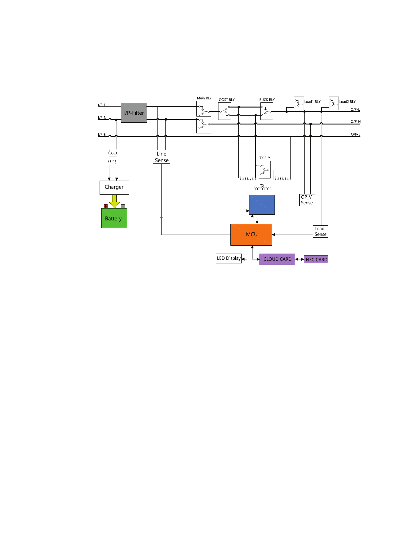
11..11 OOvveerrvviieeww
B
Full-Bridge
Inverter
The AVR750UNC line interactive UPS system provides reliable battery backup and AC power protection against
blackouts, brownouts, over-voltages, surges, and line noise that can damage valuable electronics or destroy
data. The AVR750UNC battery backup is the ideal protection for your home office, media center or professional
kiosk, security and small-business phone applications, computers, routers, printers, HDTVs, Blu-ray players,
game consoles, ATMs, security systems, and digital signage equipment.
Backup support allows you to work through short power failures and gives you enough time to save files safely
and shut down your system in case of a prolonged blackout. Backup time varies according to load, but the UPS
should keep an energy-efficient desktop computer with a small LCD monitor powered for as long as 11
minutes. In Line Mode, incoming utility power keeps the replaceable internal battery fully charged, so backup
power will always be available.
Various electromagnetic and radio sources in virtually every home and business can cause disruptive
interference on the AC line. Known as electromagnetic interference (EMI) and radio frequency interference
(RFI), this line noise is a common cause of performance problems. It can lead to incremental hardware damage,
data corruption, and audio/video transmission problems. The UPS incorporates technology that filters out
disruptive line noise so it won’t affect your equipment.
The Eaton Tripp Lite Series AVR750UNC line interactive cloud-connected UPS system utilizes the Eaton
Remote Monitoring Application supported by Eaton’s Brightlayer platform so that users can connect to their
UPS anywhere. Receive alerts, control outlets, or shutdown devices – all from the touch of a mobile device or
desktop computer.
Other key features include:
• Replaceable battery.
2 Eaton Tripp Lite Series Cloud Connected UPS System User Guide 934927—Rev B
• Compact housing with easy desktop or wall mount installation option.
• Auto-restart during AC recovery.
• Overload protection when operating on AC and Battery modes.
• Input voltage out-of-range protection.
11..22 PPaacckkaaggee CCoonntteennttss
Table 1. Package Contents
Contents
UPS
Quick start manual
11..33 DDiimmeennssiioonnss
Figure 1. AVR750UNC (AG-0786) Dimensions
305
[12”]
190
[7.4”]
106
[4”]
Package Contents
Eaton Tripp Lite Series Cloud Connected UPS System User Guide 934927—Rev B 3
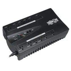
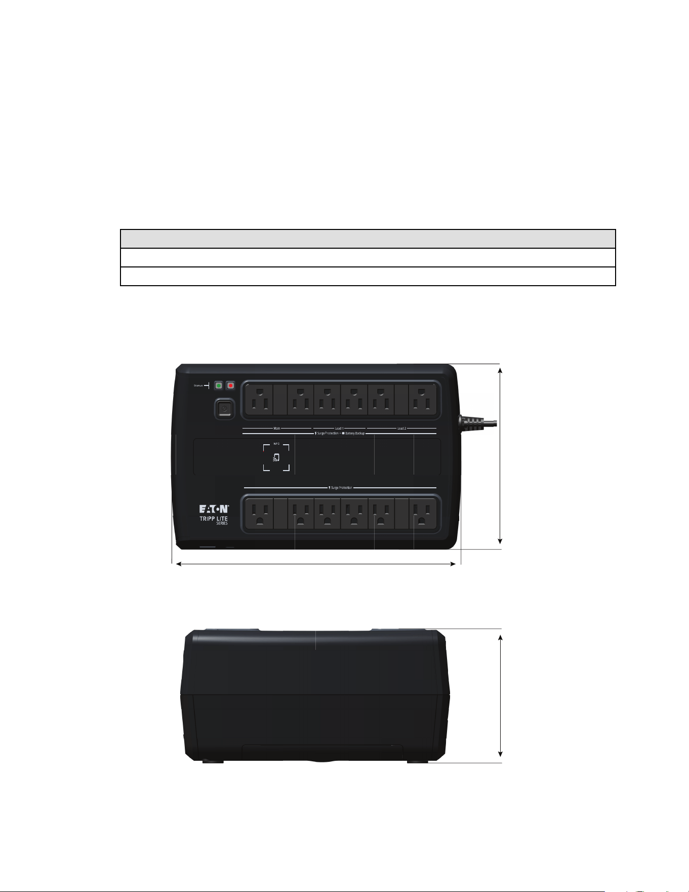
11..44 PPhhyyssiiccaall FFeeaattuurreess
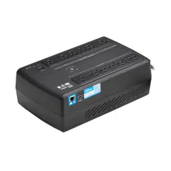
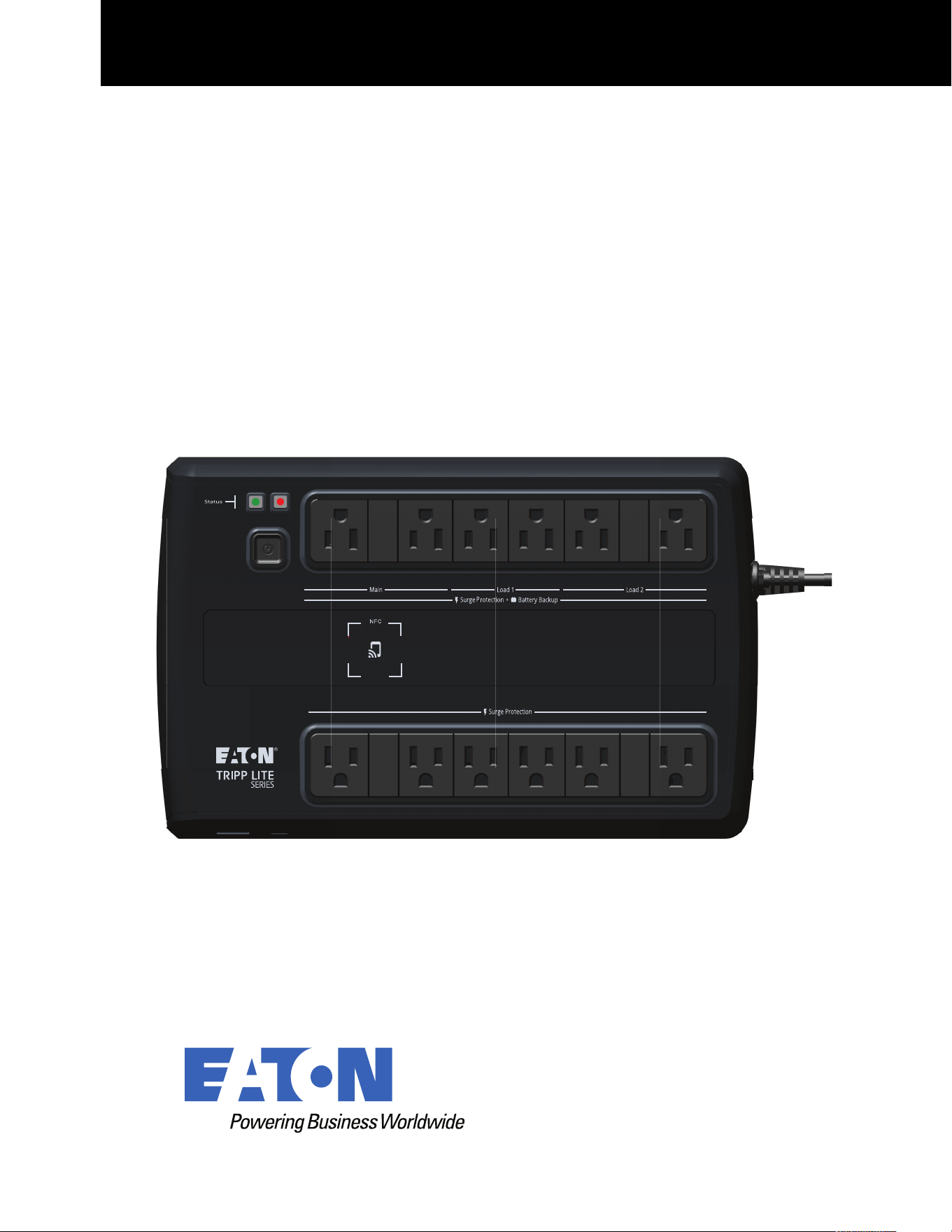
Figure 2. AVR750UNC(AG-0786)
Surge-only protected outlets
Battery-protected outlets- Main
Switched battery-protected outlets- Load 1
Switched battery-protected outlets- Load 2
Line and alarm status indicators
Power button
Near Field Communication location (NFC)
Circuit breaker
Input line cord
Ethernet port
USB-C configuration port
1
2
3
4
5
6
7
8
9
10
11
1
2
3
4
6
7
8
9
10 11
5
Physical Features
4 Eaton Tripp Lite Series Cloud Connected UPS System User Guide 934927—Rev B
CChhaapptteerr 22 IInnssttaallllaattiioonn aanndd OOppeerraattiioonn
22..11 UUPPSS IInnssttaallllaattiioonn
The Eaton Tripp Lite Series AVR750UNC UPS System is easily installed on a desktop or a shelf. Keyhole
mounting tabs on the rear of the UPS allow for easy wall-mount installation.
Remove the UPS from its packaging and inspect it for damage that may have occurred during shipping. If any
damage is discovered, re-pack the UPS and contact your Local Distributor or Eaton Support.
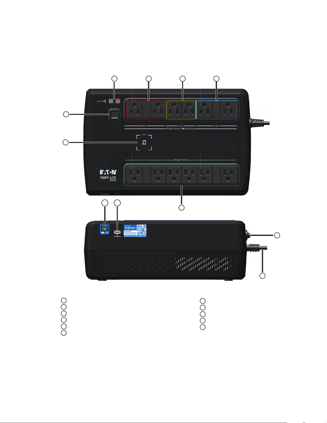
22..22 SSttaannddaarrdd MMoouunnttiinngg IInnssttaallllaattiioonn
The Tripp Lite Series AVR750UPS UPS system, can be installed in the following standard mounting orientation.
NOTE 1 Do not install the unit on its sides. The UPS can become unstable and tip over, causing
damage to the product.
NOTE 2 Install the UPS on a hard, flat, smooth surface to avoid blocking the air vents next to the
battery compartment.
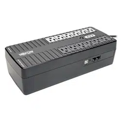
Figure 3. Standard Mounting
Standard mounting orientation
22..33 WWaallll MMoouunntt IInnssttaallllaattiioonn
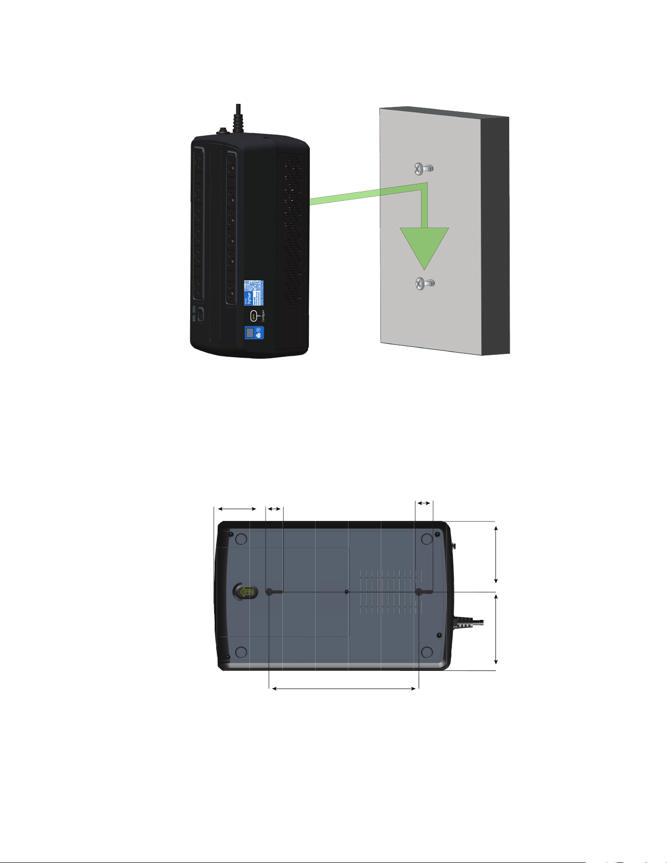
The Tripp Lite Series AVR750UNC UPS system should be installed directly into the center of a wood wall stud
for mounting the UPS in a vertical orientation. Use the appropriate anchoring methods for other wall material
types to ensure the UPS is securely mounted and supported.
UPS Installation
Eaton Tripp Lite Series Cloud Connected UPS System User Guide 934927—Rev B 5
To secure the UPS, follow the below steps:
1. Measure and mark the hole locations on the wall. Use a screwdriver to install the screws in the wall,
leaving the screws extended 0.28 inches.
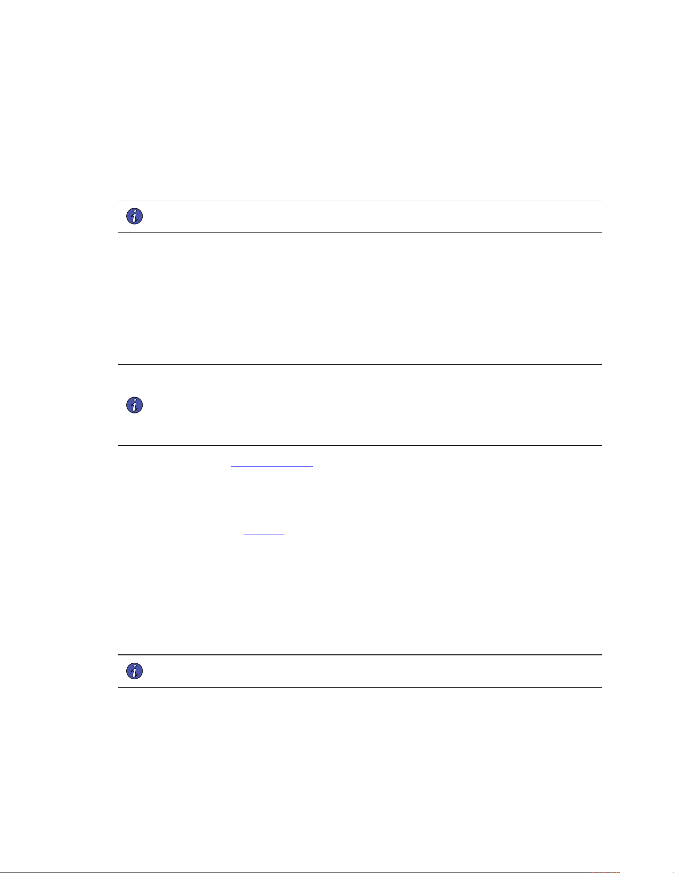
Figure 4. AVR750UNC (AG-0786 ) Wall Mounting Hole Dimensions
90
[3.5”]
100
[4.0”]
190
[7.5”]
22.5
[0.8”]
65.5
[2.6”]
22.5
[0.8”]
2. Center the UPS keyhole openings over the screw heads, push towards the wall, and then down lightly to
lock the UPS onto the screws.
Wall Mount Installation
6 Eaton Tripp Lite Series Cloud Connected UPS System User Guide 934927—Rev B
3. To detach the UPS from the wall, lightly push up on the bottom of the UPS to release it from the wall.
4. Carefully lift the UPS off the wall.
22..44 TTuurrnniinngg tthhee UUPPSS OOnn
For normal AC startup of the UPS, follow these steps:
1. Connect the UPS AC power cord to a properly grounded NEMA 5–15R wall outlet.
NOTE Once the UPS is plugged into a wall outlet, the battery charger will engage as
necessary, and the SURGE ONLY outlets will begin passing power.
2. Press the power button for half a second to turn on the UPS. The UPS will beep, and the green LED will
turn on and stay illuminated. The charger will engage as necessary, and the BATTERY BACKUP outlets will
begin passing line power.
3. Plug your load equipment into the outlets on the UPS. There are two sets of outlets on your UPS. The
outlets marked SURGE ONLY do not provide battery backup power during power outages. Connect
everyday desktop items like printers, scanners, and other accessories not requiring battery support to
these outlets. The outlets marked BATTERY BACKUP offer UPS battery backup support during power
failures. The main outlet group, load one and two switched outlets, can be controlled via the Eaton Remote
Monitoring Application. Connect your vital computer equipment to these outlets.
NOTE The Tripp Lite Series AVR750UNC UPS system is designed to support electronic
equipment only. You will overload the UPS if the total volt-amp (VA) ratings for all the
equipment connected to the outlets exceeds the UPS output capacity. To find your
equipment’s VA ratings, look at its nameplate. If the equipment is listed in amps (A),
multiply the number of amps by 120 to determine VA. For example 1A × 120 = 120VA. If
you suspect you have overloaded the outlets, remove some equipment.
4. Register your UPS at tripplite.eaton.com .
22..55 OOuuttlleett CCoonnttrrooll
The Eaton Tripp Lite Series AVR750UNC UPS System outlets can be switched on and off to control connected
equipment remotely. The outlet control is located in the Device Summary Screen of the Eaton Remote
Monitoring Application. (See Figure 38).
• Surge-only protected outlets- no On/Off control available.
• Main battery protected outlets- controlled by the Device control option button.
• Switched battery protected outlet Load one / Load two– controlled by the UPS output control button.
22..66 TTuurrnniinngg tthhee UUPPSS OOffff
To turn off the UPS, hold the power button on the front panel for half a second; the UPS will beep, indicating it
is in Standby Mode. Unplug the UPS from the power source.
NOTE If the UPS is not unplugged from the wall receptacle, it remains in Standby Mode, and
the SURGE ONLY outlets will still pass line power.
22..77 LLEEDD IInnddiiccaattoorrss
The Tripp Lite Series UPS system panel indicates the UPS status via the red and green LED indicators.
Turning the UPS On

Eaton Tripp Lite Series Cloud Connected UPS System User Guide 934927—Rev B 7
Table 2. LED Status Indicators
Description Green LED Red LED Alarm Tone Notes
Line Mode On Off Off Operating in normal
line mode and the
battery is fully charged.
Battery Mode Flashes every 10
seconds
Off Off Set default is no alarm
until the event occurs
(e.g., battery low,
overload, etc.
Battery Low Flashed solid every
second
On
Beeps every second
Line Mode Overload
Alert*
On Off Beeps every 0.5 second
Battery Mode Overload
Alert**
Flashes Off Beeps every 0.5 second
Line Mode Overload
Fault*
Off On Continuously beeps
Battery Mode Overload
Fault**
Off Off Off
Replace Battery On Flashes every minute Beeps every minute
Fault Condition Off On Continuously beeps
1. Overcharge fault
2. Output short fault
*Line Mode Overload Alert Condition - 110%±10%, goes to fault after 5 minutes; Overload Fault Condition - 120%±10%, goes to
fault immediately
**Battery Mode Overload Alert Condition - 110%±10%, shuts down in 5 seconds; Battery Mode Overload Fault Condition - 120%
±10%, shuts down immediately
LED Indicators
8 Eaton Tripp Lite Series Cloud Connected UPS System User Guide 934927—Rev B
CChhaapptteerr 33 CCoommmmuunniiccaattiioonnss
33..11 CCoommmmuunniiccaattiioonn PPoorrttss
NNFFCC FFuunnccttiioonnaalliittyy
The NFC tag on the UPS enables users to collect and configure UPS settings using the Eaton Remote
Monitoring application by placing the NFC-enabled mobile device flush with the indicated NFC area on the UPS.
(See 4.1 Welcome to the Eaton Remote Monitoring Application).
EEtthheerrnneett PPoorrtt
The Ethernet Port allows the UPS to connect via a local network and managed using the Eaton Remote
Monitoring application. (See 4.1 Welcome to the Eaton Remote Monitoring Application).
UUSSBB--CC PPoorrtt FFuunnccttiioonnaalliittyy
The USB-C Port allows for local access to UPS Command Line Interface (CLI) for configuration and discovery of
the local network settings and other features. (See 3.2 Command Line Interface).
33..22 CCoommmmaanndd LLiinnee IInntteerrffaaccee
The Command Line Interface (CLI) is intended mainly for automated configuration of the network and time
settings of the Eaton Tripp Lite Series UPS. It can also be used for troubleshooting and remote reboot/reset of
the network interface in case the web user interface is not accessible.
Changing network parameters may cause the card to become unavailable remotely. If this happens it can only
be reconfigured locally through USB-C configuration port.
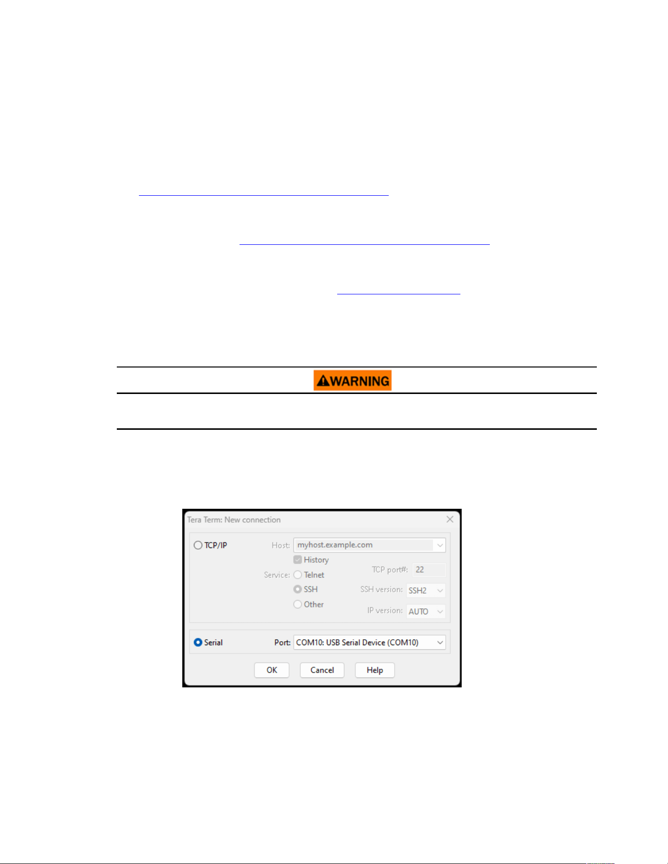
To log into the command line interface:
1. Plug a cable into the USB port of the UPS and launch a terminal emulation program.
Figure 5. Terminal Emulation Program
Communication Ports
Eaton Tripp Lite Series Cloud Connected UPS System User Guide 934927—Rev B 9
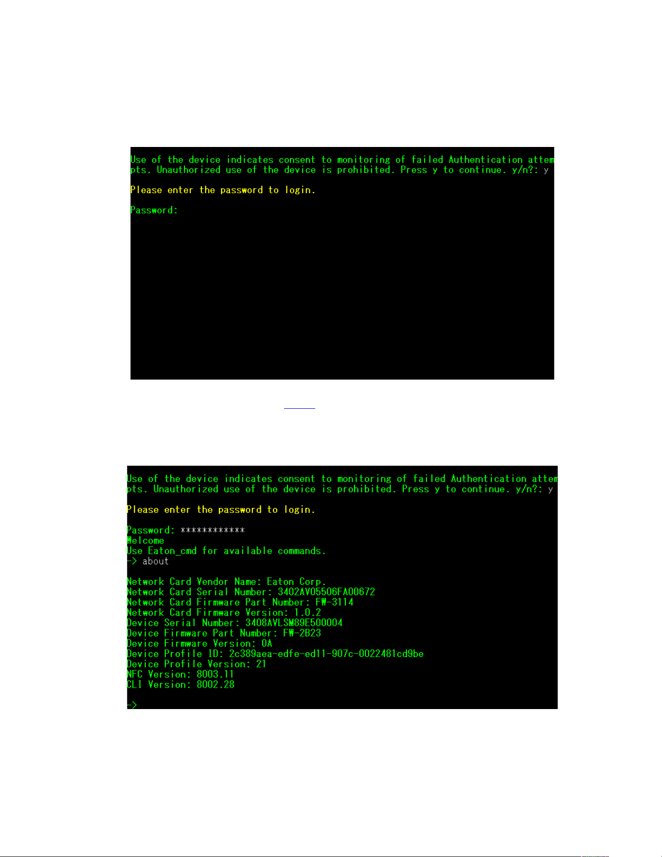
2. Press “y” to continue onto the login screen and enter the device password.
Figure 6. Enter Password
3. Enter a User Command from Table 3 and press the Enter button.
4. The information will be displayed on the screen.
Figure 7. Command Output
Command Line Interface

10 Eaton Tripp Lite Series Cloud Connected UPS System User Guide 934927—Rev B
Table 3. CLI Commands
User Command Name Description Sample Input/Output Note
login login to the shell <password> Only used for entering to shell It gets the
current password as input
logout logout of the shell N/A This command prompt you to login after logout
set_new_password Set a new password
"Pa$sw0rd"
The default value is "password". New
Password has following limits:
1. The length must be at least 8 and max 16
characters.
2. The string is alphanumeric case
sensitive.
3. The new password must at least have
one digit, one upper case, one lower
case, and one special case characters.
4. The previous password is required to
enter.
5. The new password must be entered
twice.
set_ipv4_maskaddr Set the subnet mask
address
255.255.255.0
This value will initialize as “0.0.0.0” if the
device is not connected to the internet. The
default restore IP address is "192.168.1.254".
get_ipv4_maskaddr Get the assigned subnet
mask address
255.255.255.0
set_ipv4_addr Set the assigned IP
address
192.168.0.133
get_ipv4_addr Get the assigned IP
address
192.168.0.133
set_ipv4_gateway Set the IP gateway
192.168.0.1
get_ipv4_gateway Get the IP gateway
192.168.0.1
get_ipv4_method Get the IP method IP Method set as static/
DHCP.
The default value is DHCP.
set_ipv4_method_dhcp Set DHCP IP IP Method set as DHCP
get_mac_addr Get MAC Address
00:00:00:00:00:00
get_proxy_addr Get the assigned proxy
address
PROXY Address is -
proxy.apac.etn.com
set_proxy_addr
Set the proxy address
Proxy address
reconfigured
successfully.
The length must be less than 20 characters
get_proxy_port
Get the port PROXY port is - 8080
set_proxy_port
Set the port Proxy port number
reconfigured
successfully.
Any range between 0-65535
Command Line Interface

Eaton Tripp Lite Series Cloud Connected UPS System User Guide 934927—Rev B 11
Table 3. CLI Commands (Continued)
User Command Name Description Sample Input/Output Note
get_proxy_status
Get the status of proxy PROXY is not enabled.
set_proxy_disable Disable proxy PROXY is disabled.
set_proxy_enable Enable proxy PROXY is enabled.
set_proxy_username
Set the proxy username
<username>
Sets the username for proxy. The length of
username must not exceed 21 characters.
set_proxy_password Set the proxy password <password> Sets the username for proxy. The length of
username must not exceed 21 characters.
get_proxy_username
Get the proxy username PROXY username is
<username>
get_proxy_password Get the proxy password PROXY password is
<password>
This will print out stars(*) only after
commissioning
get_sntp_server1
Get the SNTP Server 1 IP
address or Host Name
SNTP server 1 IP
Address/Domain name:
129.6.15.28
get_sntp_server2
Get the SNTP Server 2 IP
address or Host Name
SNTP server 2 IP
Address/Domain name:
132.163.96.1
get_sntp_server3
Get the SNTP Server 3 IP
address or Host Name
SNTP server 3 IP
Address/Domain name:
132.163.97.1
get_sntp_status
Get SNTP Server status SNTP service enabled.
get_sntp_service Get SNTP Server
connection
SNTP service connected
to server 1.
set_sntp_disable Set SNTP Server disable SNTP server disabled
successfully.
set_sntp_enable
Set SNTP Server enable SNTP server enabled
successfully.
get_primary_dns Get the primary dns Primary DNS: 8.8.8.8
get_secondary_dns Get the secondary dns Secondary DNS:
192.168.0.1
get_time
Get the current time of
system
Epoch Time from RTC
(seconds) - 1692282558
Time since epoch
get_iot_connection_
status
Get IOT connection status IOT Connection is
enabled.
get_iot_connection Get IOT DPS connection IOT Connected.
get_iot_connection_
reason
Get IOT Connection
status and reason.
IoT initial state.
get_iot_dps_endpoint Get IOT DPS endpoint. IOT DPS endpoint -
global.azure-devices-
provisioning.net
Command Line Interface

12 Eaton Tripp Lite Series Cloud Connected UPS System User Guide 934927—Rev B
Table 3. CLI Commands (Continued)
User Command Name Description Sample Input/Output Note
about Print out versions and
serial numbers
Network Card Serial
Number
Network Card Firmware
Part Number: FW-3114
Network Card Firmware
Version: 0.9.0
Device Serial Number:
3302AVLBC884A00019
Device Firmware Part
Number: FW-2B13
Device Firmware
Version: 02
Device Profile ID:
2c389aea-edfe-ed11-
907c-0022481cd9be
Device Profile Version:
16
NFC Version: 8003.6
CLI version: 8002.22
Network Card Serial number will be shown
once it's set.
get_device_connection Get the deviceID and
ConnectionString
Device GUID/UUID -
<device GUID/UUID>
Device Connection String
- <Connection String>
This will print out stars(*) for connection string
only after commissioning
dump_json_formatted_
logs
DEBUG: Dump JSON
formatted logs
Output size might be bigger than 200
characters
clear_logs Clear all logs from NV
show_logs Show all logs Event Log is currently
Empty!
Output size might be bigger than 200
characters
reboot_card Reboot the card N/A
Keep the last changes(if any) to the network
settings(IPV4) and password intact. This
command reboots the card to complete the
network settings configuration.
factory_reset_card Factory reset the card N/A
Returns the network settings (IPV4) and
password back to default values.
Command Line Interface
Eaton Tripp Lite Series Cloud Connected UPS System User Guide 934927—Rev B 13
CChhaapptteerr 44 RReemmoottee MMoonniittoorriinngg AApppplliiccaattiioonn
44..11 WWeellccoommee ttoo tthhee EEaattoonn RReemmoottee MMoonniittoorriinngg AApppplliiccaattiioonn
The Eaton Tripp Lite Series cloud-connected UPS systems are managed by the Eaton Remote Monitoring
Application supported by Eaton's Brightlayer platform so that users can connect to their UPS anywhere.
Receive alerts, control outlets, or shutdown devices – all from the touch of a mobile device or desktop
computer. Whether a user is setting up one or several units, commissioning has never been more
straightforward. The Eaton Remote Monitoring Application can be downloaded from the Apple or Android app
stores.
44..22 UUsseerr EEnnrroollllmmeenntt aanndd AAccttiivvaattiioonn
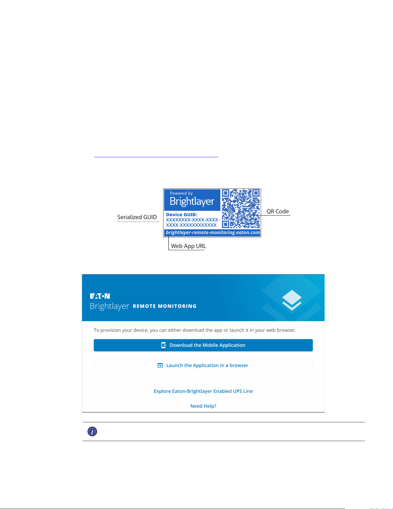
1. Locate and scan the QR code on the left-hand side of the UPS cover or visit the direct link
Eaton Brightlayer Remote Monitoring Application to launch the application in a web browser or to
download it to a remote Device.
Figure 8. QR Code Location
Serialized GUID
Web App URL
QR Code
Figure 9. Web Application Page
NOTE Chrome, Firefox, Edge, and Safari are the supported internet browsers. Do not use
Microsoft Internet Explorer.
14 Eaton Tripp Lite Series Cloud Connected UPS System User Guide 934927—Rev B
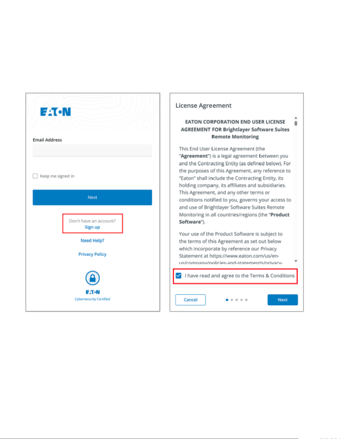
2. Click the Sign-Up link on the login screen.
3. Please read and check the box agreeing to the EATON CORPORATION END USER LICENSE
AGREEMENT FOR Brightlayer Software Suites Remote Monitoring. Then click Next.
Figure 10. Sign In Screen and End User License Agreement
User Enrollment and Activation
Eaton Tripp Lite Series Cloud Connected UPS System User Guide 934927—Rev B 15
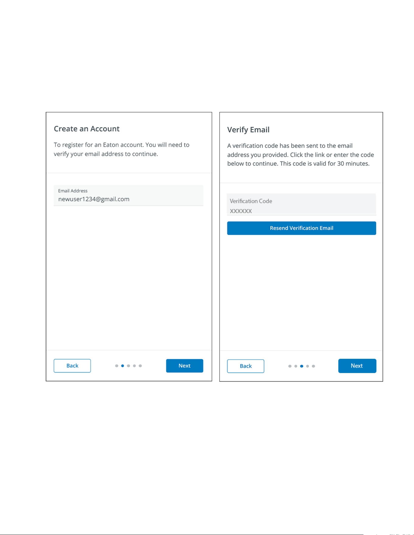
4. Enter a valid email address to verify your account. A verification code will then be sent to your email
account. Click Next. Click Next.
5. Enter the verification code and click Next.
Figure 11. Create an Account and Verify Code
User Enrollment and Activation
16 Eaton Tripp Lite Series Cloud Connected UPS System User Guide 934927—Rev B
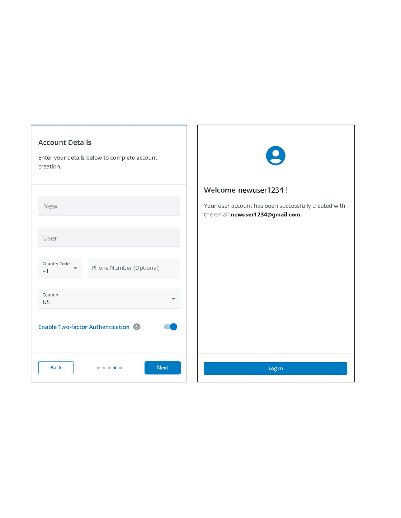
6. Enter the account information to complete the account creation. Eaton recommends that the Two-factor
Authentication option remain enabled to prevent unauthorized access to the account. When finished, click
Next.
7. The new user account has now been created; press. Press the log-in button, and an email notification will
be sent to activate the account.
Figure 12. Account Details
User Enrollment and Activation
Eaton Tripp Lite Series Cloud Connected UPS System User Guide 934927—Rev B 17
8. Click the Activate Account button provided in the email notification.
Figure 13. Email Activation Notification
9. Click on Set up to set up an account password.
Figure 14. Set Up Password Screen
User Enrollment and Activation
Eaton Tripp Lite Series Cloud Connected UPS System User Guide 934927—Rev B 21
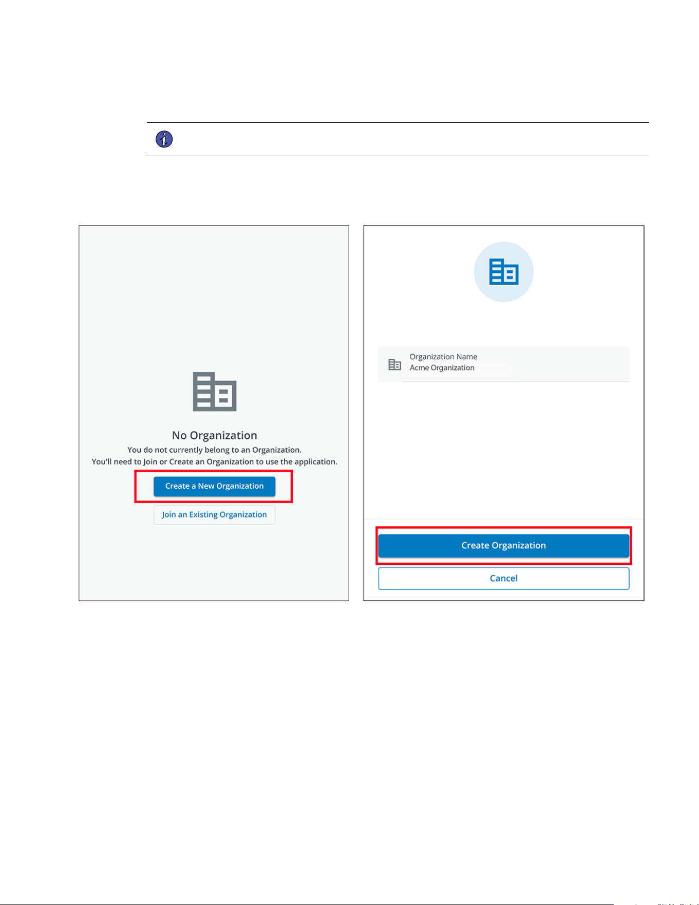
15. Click Create a New Organization .
NOTE If joining an existing organization, contact the administrator to obtain the organizational
code and clickJoin and Existing Organization.
16. Enter the name of the new organization. Click Create Organization.
Figure 18. Create a New Organization
User Enrollment and Activation
Eaton Tripp Lite Series Cloud Connected UPS System User Guide 934927—Rev B 23
44..33 UUsseerr IInntteerrffaaccee
The Eaton Remote Monitoring Application includes a simple summary and detailed views of the connected
devices. You can view it with a computer browser, such as Google Chrome™, or any mobile device.
NOTE Occasionally clear the browser cache, click the reload button to refresh the Remote
Monitoring app, or adjust your browser resolution settings. New features and updates
will be released over time, and clearing the browser cache or adjusting the browser
resolution settings corrects login or data visibility issues.
44..44 LLooggiinn SSccrreeeenn
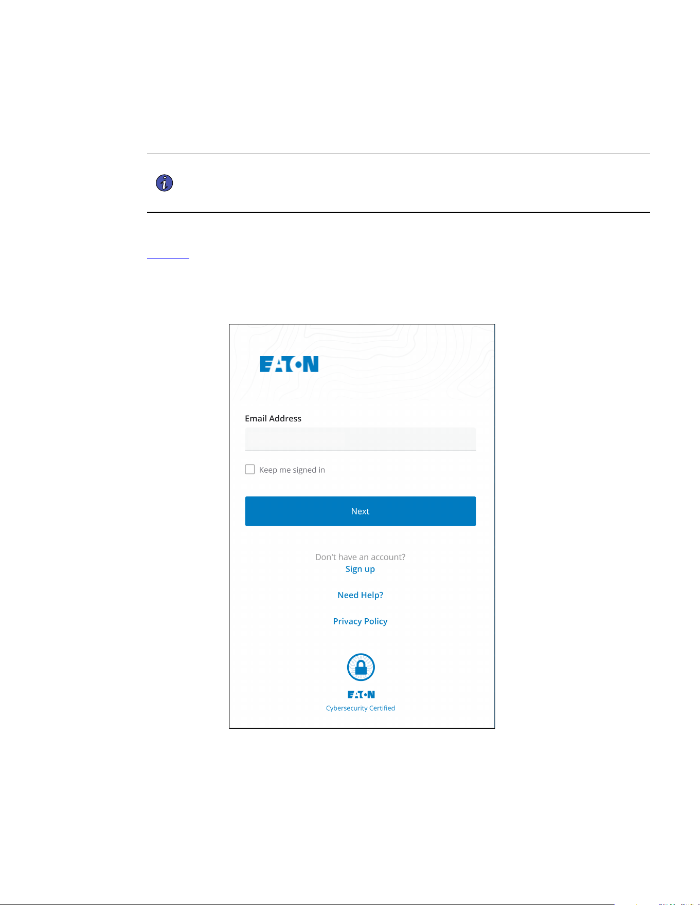
Figure 21 shows the Eaton Remote Monitoring Application login screen viewed on an internet browser. From
the login screen, the user can enter a new enrollment, reset the password, or log in to open the application's
overview (home) screen.
Figure 21. Login Screen
User Interface
24 Eaton Tripp Lite Series Cloud Connected UPS System User Guide 934927—Rev B
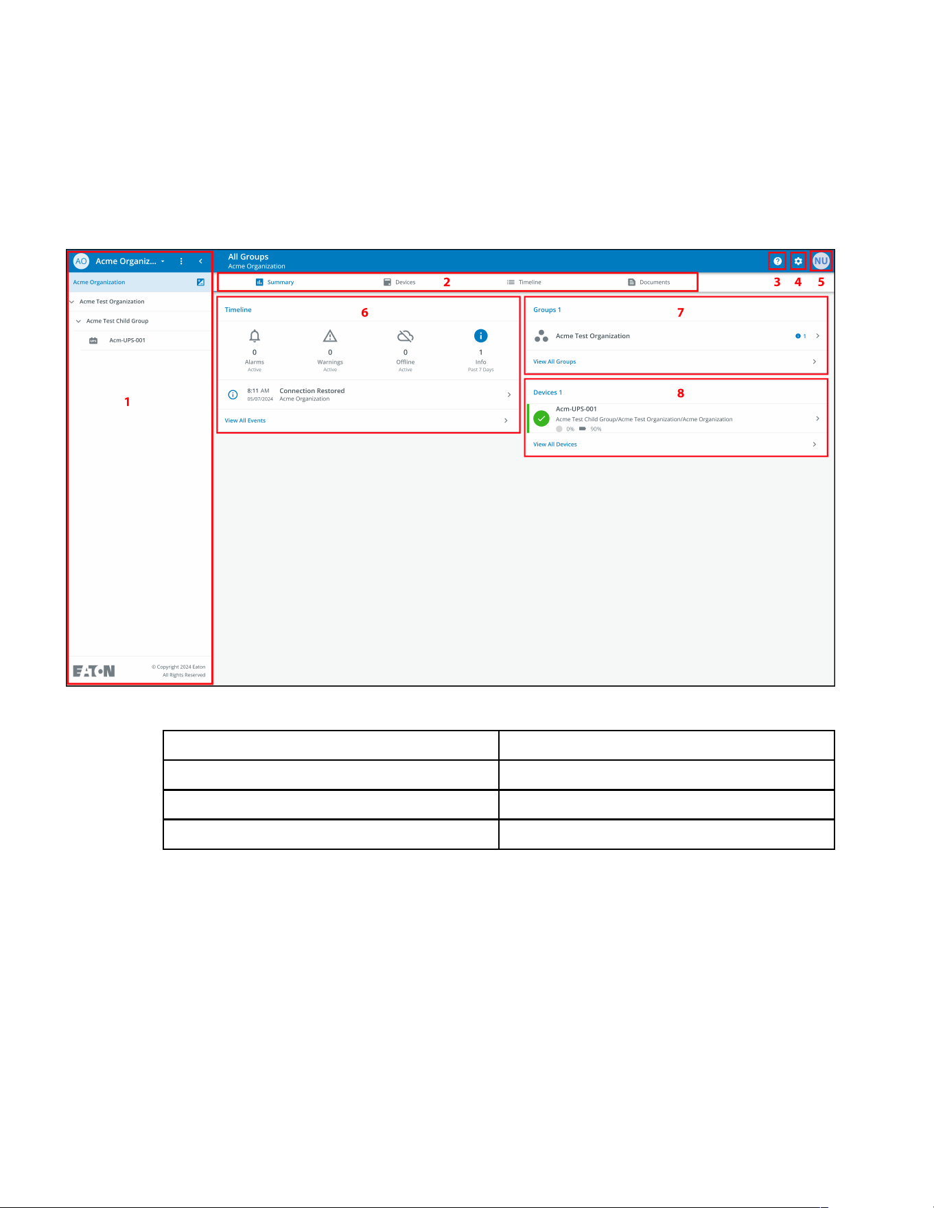
44..55 OOrrggaanniizzaattiioonnaall SSuummmmaarryy SSccrreeeenn
The Organizational Summary Screen displays information for all organizational groups and devices, providing
easy-to-navigate paths to display information.
Figure 22. Organizational Summary Screen
Table 4. Organizational Summary Screen Sections
① Organizational Hierarchy Menu ⑤ User Menu
② Tabs Menu ⑥ Timeline Widget
③ Help Menu ⑦ Groups Widget
④ Settings Menu ⑧ Devices Widget
Organizational Summary Screen
Eaton Tripp Lite Series Cloud Connected UPS System User Guide 934927—Rev B 25
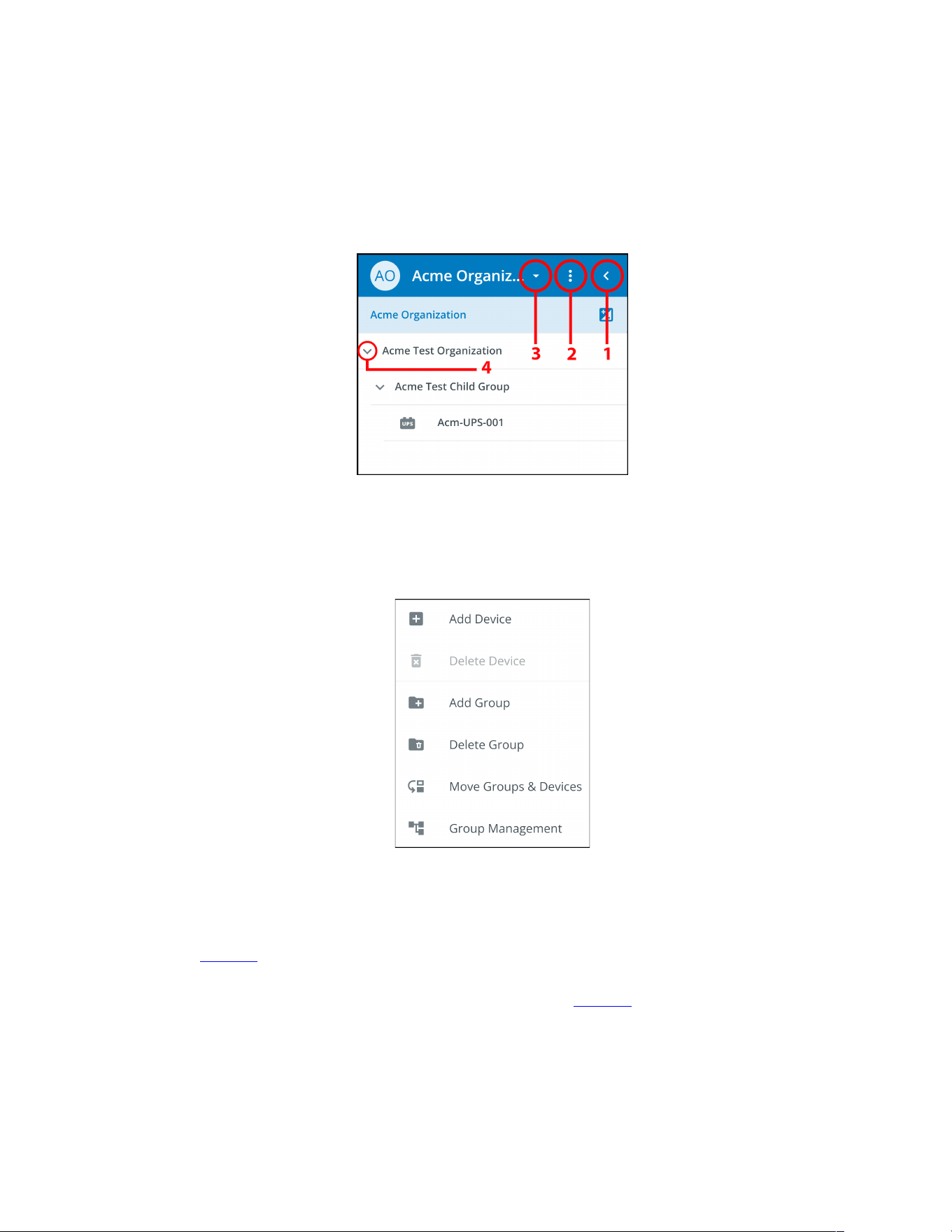
44..55..11 OOrrggaanniizzaattiioonnaall HHiieerraarrcchhyy MMeennuu
The Organizational Hierarchy Menu manages organizational hierarchy and Devices and allows users to switch
between Organizations and Groups.
Figure 23. Organizational Hierarchy Menu
1. Hides or displays the Organizational Hierarchy.
2. Displays the Organizational Hierarchy function to manage Groups and Devices.
Figure 24. Organizational Hierarchy Menu Options
3. Switches between Organizations if more than one exists.
4. Displays the Organizational Hierarchy.
Selecting a Group in the Organizational Hierarchy Menu will display the Organizational Summary Screen see
Figure 22 .
Selecting a Device in the Organizational Hierarchy Menu will display the Device Summary Screen, which
provides essential information on the status of the UPS. See Figure 38 .
Organizational Summary Screen
26 Eaton Tripp Lite Series Cloud Connected UPS System User Guide 934927—Rev B
44..55..22 TTaabbss MMeennuu
The Tabs Menu summarize all of the data for the selected Organization, Group, or Device, as selected in the
Organizational Hierarchy Menu.
Figure 25. Tabs Menu
• Summary Tab- displays information for each Organization, Group, or Device as selected in the
Organizational Hierarchy Menu.
• Devices Tab- when selected, the Device Management Screen displays all devices set up within an
Organization and controls
adding or editing those devices.
• Timeline Tab- provides an overall summary of events for a specific Organization or Group that can be
exported into a .csv file.
• Documents Tab- displays Eaton’s Cloud-Connected User’s Guide and sales brochure files.
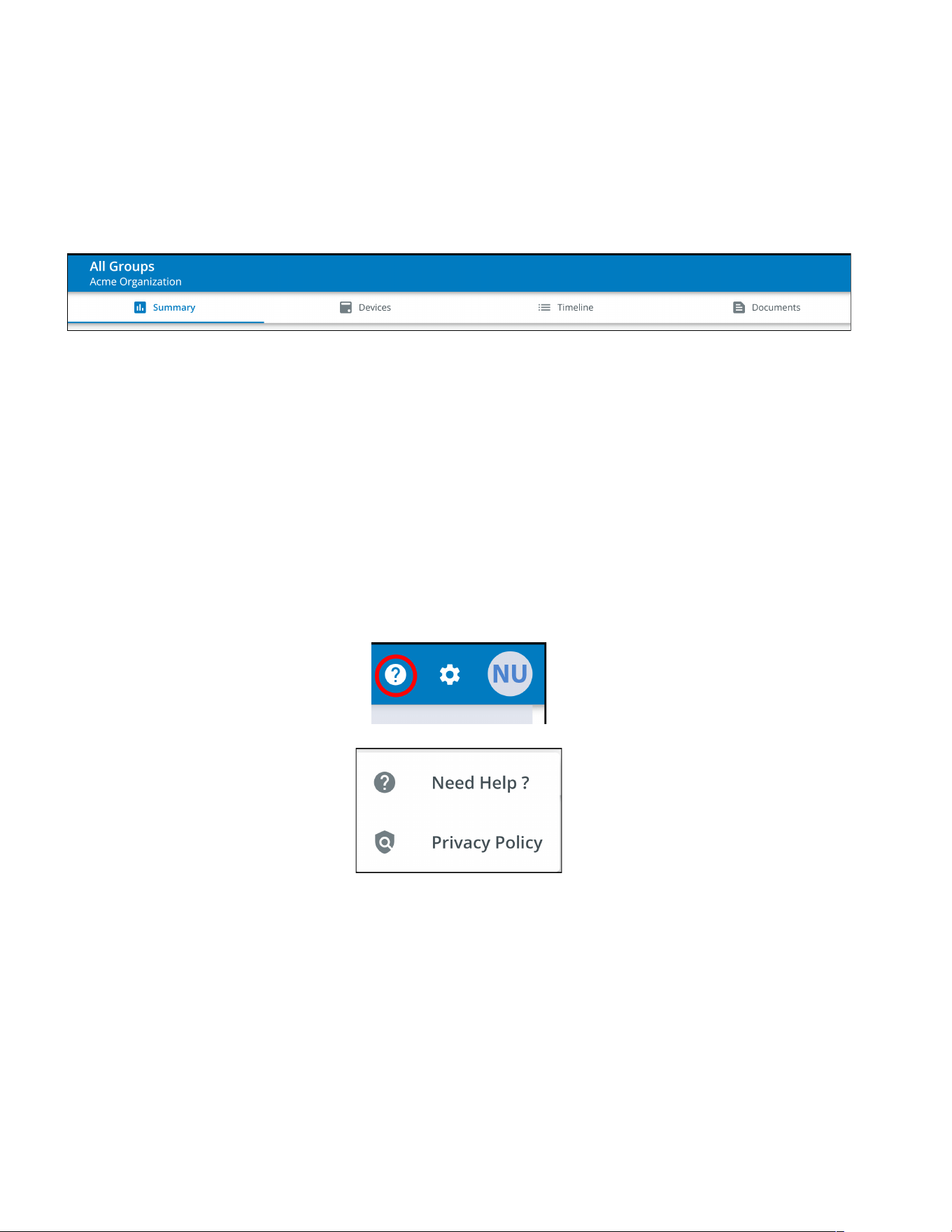
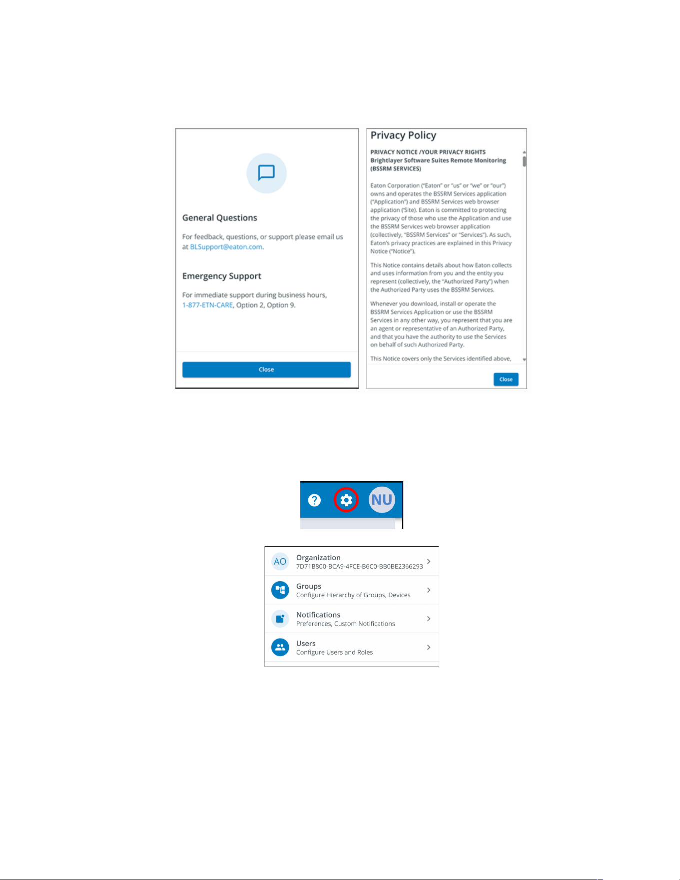
44..55..33 HHeellpp MMeennuu
Help Menu- clicking on this menu will explain how to contact Eaton for help and the privacy policy.
Figure 26. Help Menu Location
Organizational Summary Screen
28 Eaton Tripp Lite Series Cloud Connected UPS System User Guide 934927—Rev B
• Organizational Management Settings- displays all of the settings available to manage an Organization
(see Figure 20).
• Group Management- add, edit, move, or delete Groups within an Organization (see
4.7 Creating a Group Within An Organization).
• Notification Settings- set and configure alarm, warning, and event notifications via email or text (SMS).
Custom Notifications can also be set (see Figure 55 and Figure 56).
• User Management Settings- allows administrators to invite other users or coworkers to enroll in the
Eaton Remote Management Application either as users or as administrators. It also provides control over
deleting, disabling, or enabling user accounts (see 4.6 Managing Users).
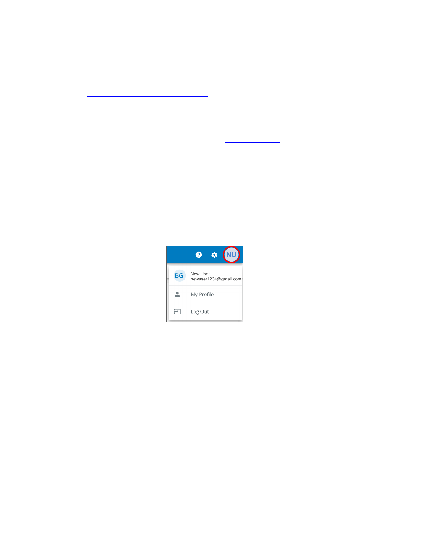
44..55..55 UUsseerr MMeennuu
The User Menu can be accessed by clicking on the User avatar in the upper right-hand corner of the Main
Organization Screen providing an option to view or edit profile settings or to log out of the application.
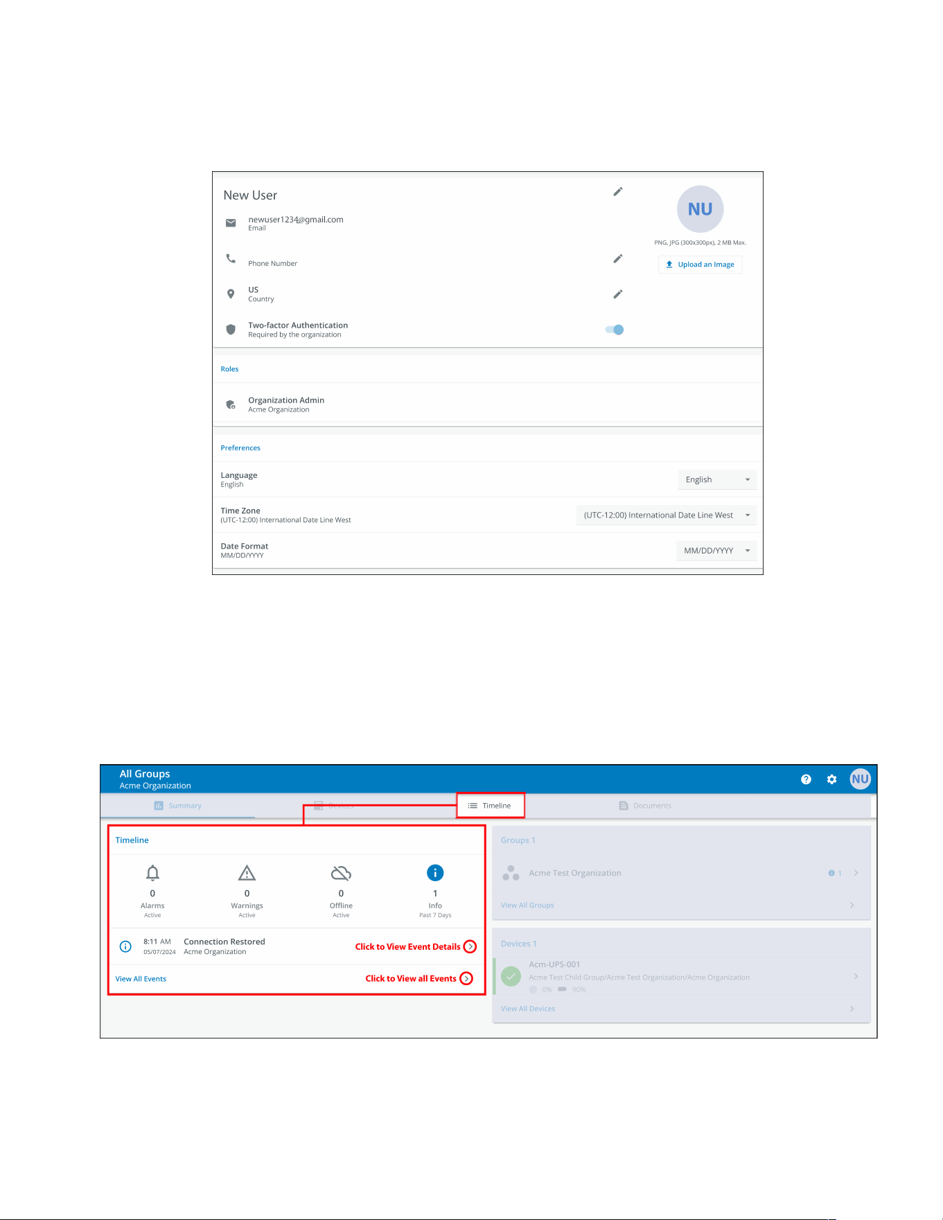
The first section of the user profile page includes general profile information, such as email, phone number,
country, an option to enable multi-factor authentication, and a location to upload an image.
The second section is the role that the User holds within the Organization.
The third section displays customizable language, time zone, and date format options.
Figure 29. User Menu
Organizational Summary Screen
Eaton Tripp Lite Series Cloud Connected UPS System User Guide 934927—Rev B 29
Figure 30. User Profile Screen
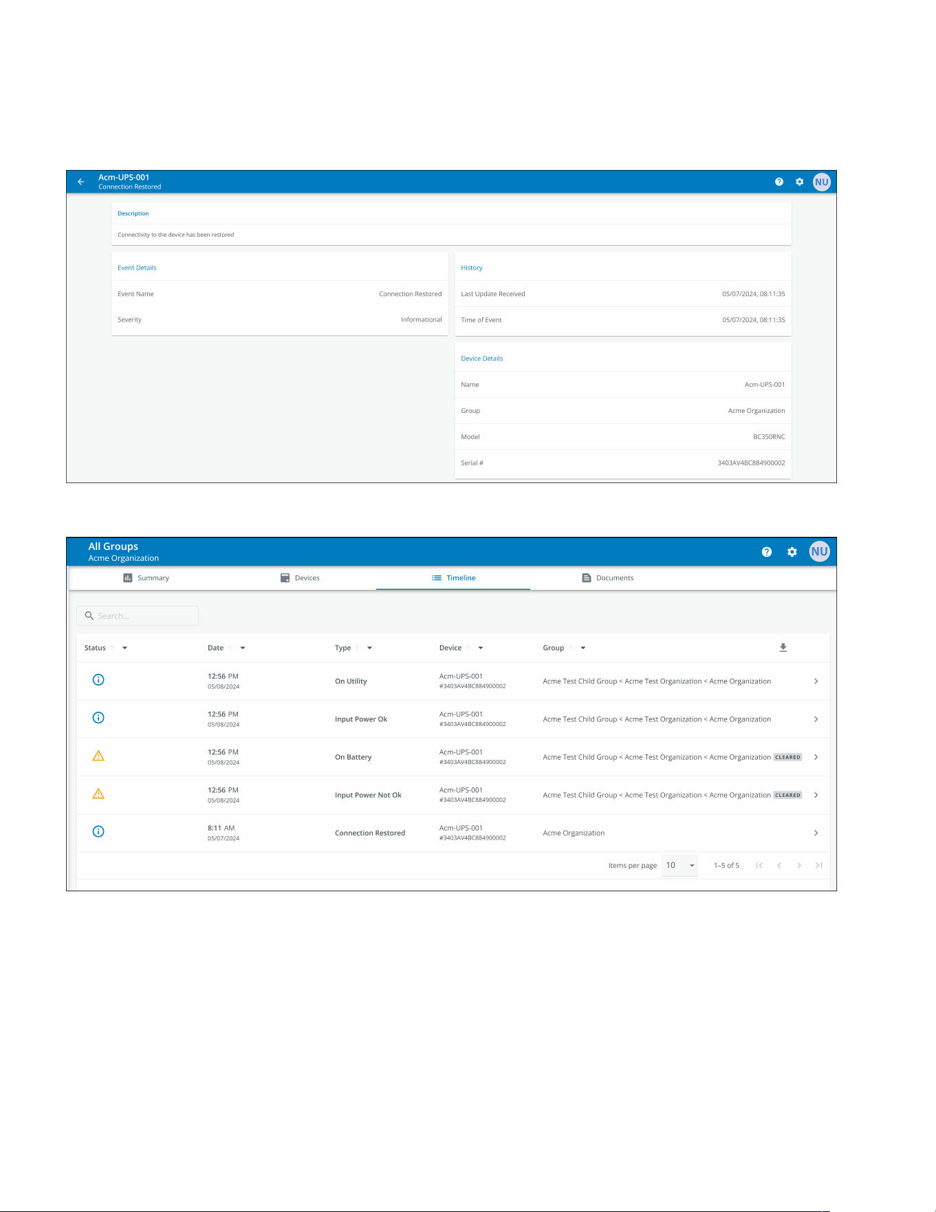
44..55..66 TTiimmeelliinnee TTaabb
The Timeline information section is a valuable tool that displays active or inactive alarms and events for the
whole Organization. It provides a link to the specific event details and a crucial link to the Event Management
screen. This screen is where you can export events into a .csv file, a feature that greatly aids in data analysis
and reporting. This comprehensive feature helps keep track of all critical events and alarms and can be
accessed via the Timeline navigation tab.
Figure 31. Timeline Widget
Organizational Summary Screen
Eaton Tripp Lite Series Cloud Connected UPS System User Guide 934927—Rev B 31
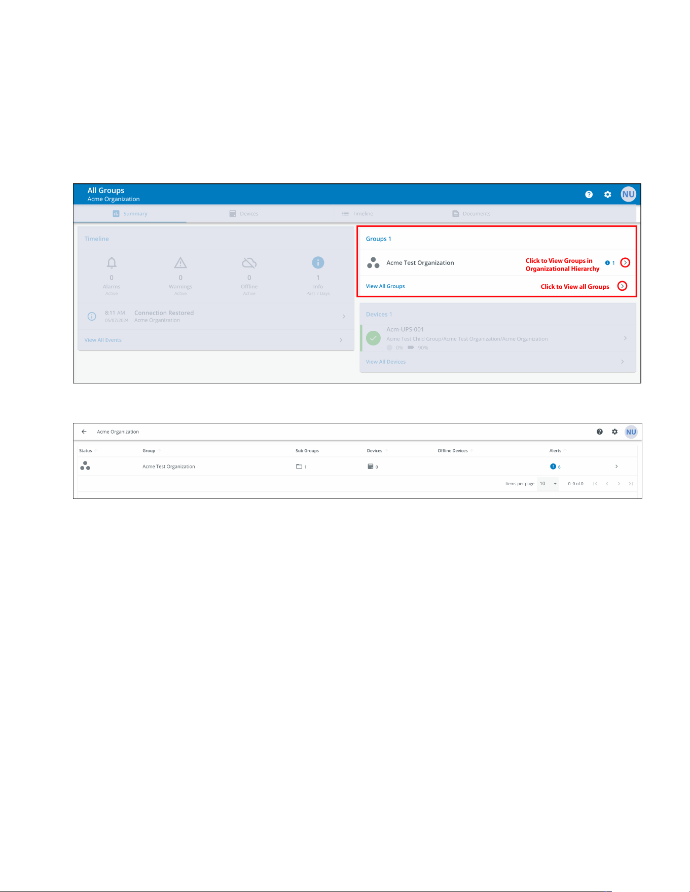
44..55..77 GGrroouuppss WWiiddggeett
The Groups Widget provides a view of Groups or Child Groups within an Organizational hierarchy and allows
users to view all Groups within an Organization.
Figure 34. Groups Widget
Figure 35. View All Groups
Organizational Summary Screen
32 Eaton Tripp Lite Series Cloud Connected UPS System User Guide 934927—Rev B
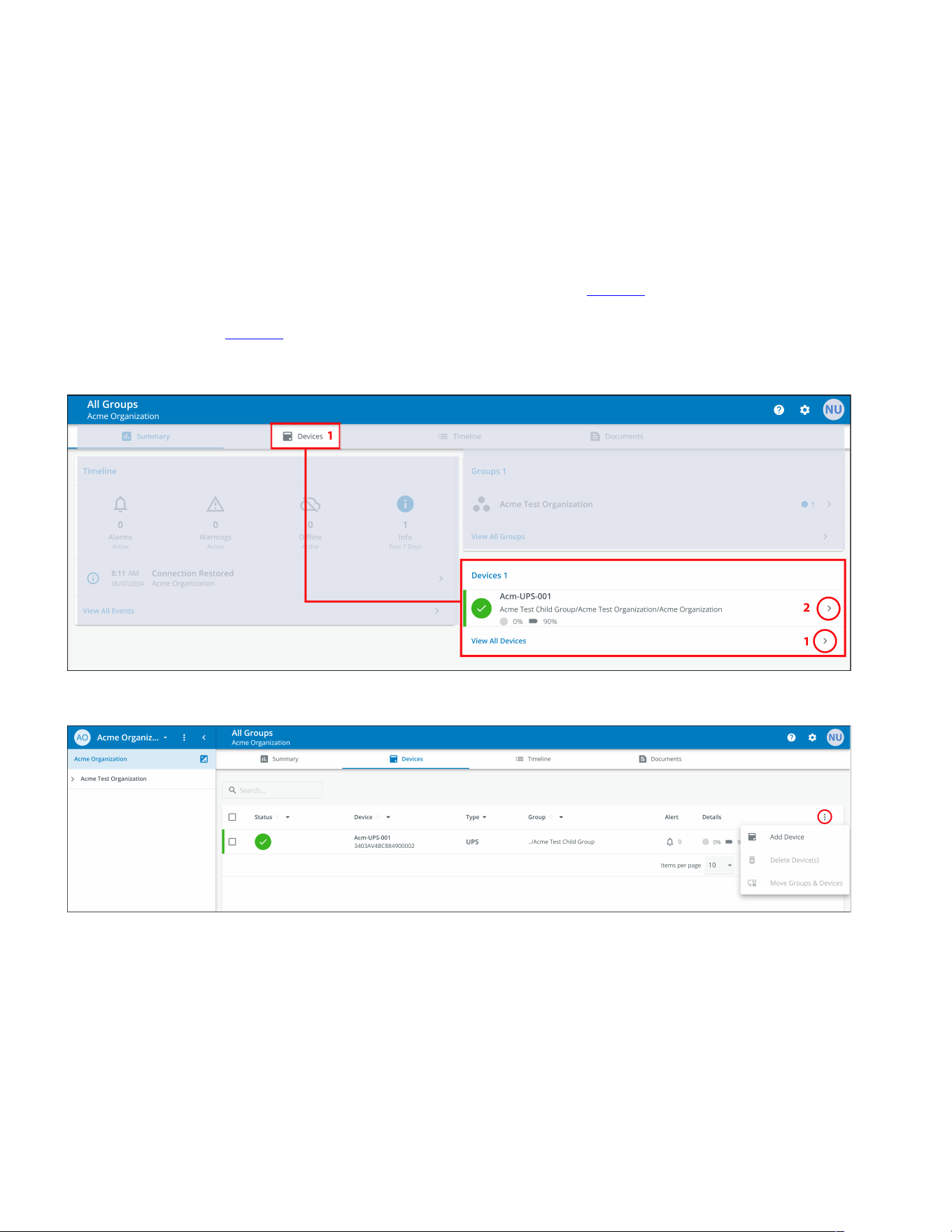
44..55..88 DDeevviiccee WWiiddggeett
Devices can be viewed and managed by selecting the options on the Main Application Page or utilizing the
Organizational Hierarchy.
VViieewwiinngg DDeevviicceess MMaaiinn AApppplliiccaattiioonn PPaaggee
Click on any of the following areas to view a specific screen to view or manage a Device:
1. Navigates to the Device Management Screen, which lists the Devices associated with the Organization
account and allows users to move, add, or delete Devices. (See Figure 37).
2. Navigates to the Device Summary Screen and allows users to display all the details for a specific Device.
(See Figure 37).
Figure 36. Device Widget
Figure 37. Device Management
Organizational Summary Screen
Eaton Tripp Lite Series Cloud Connected UPS System User Guide 934927—Rev B 33
TThhee DDeevviiccee MMaannaaggeemmeenntt SSccrreeeenn
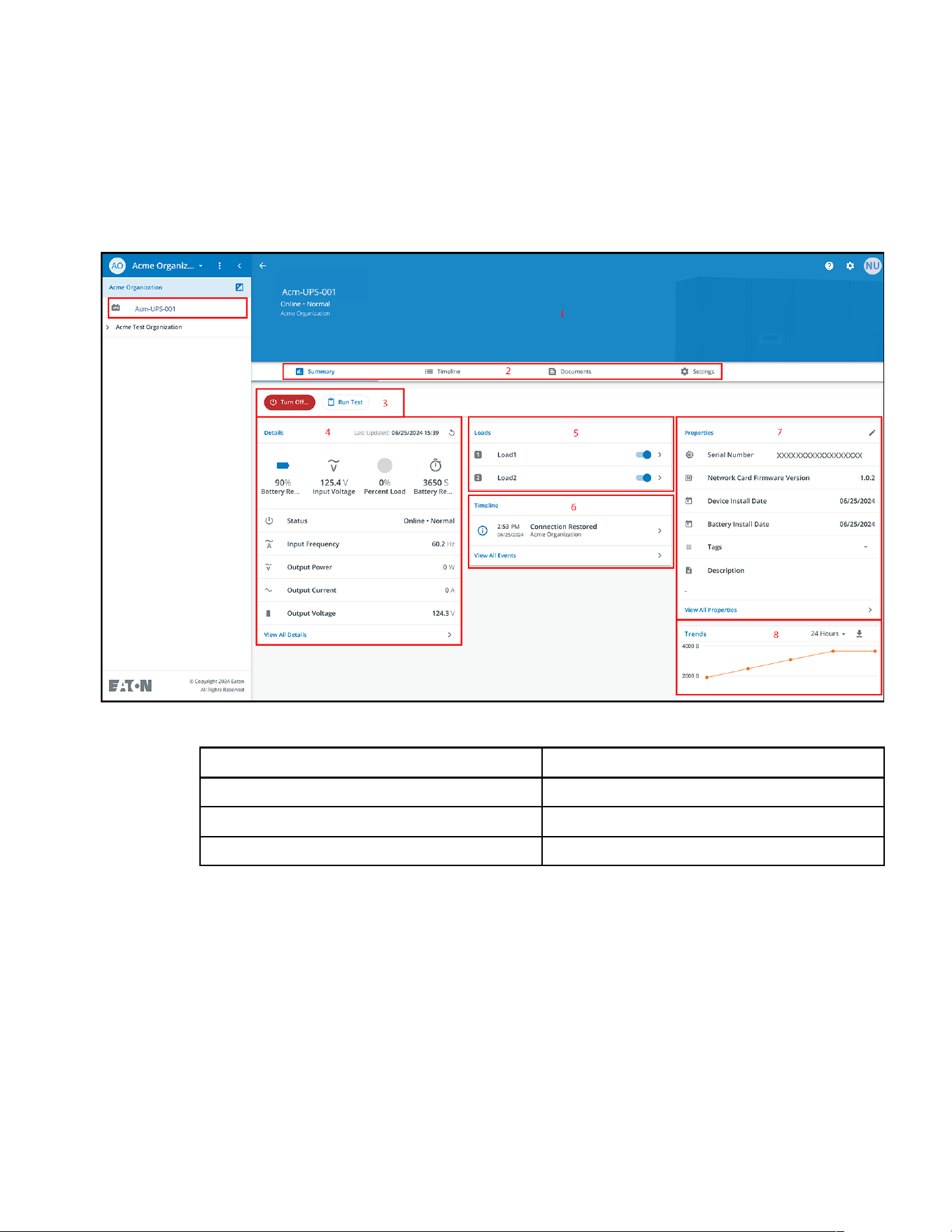
The Device Summary Screen provides a real-time operational snapshot of all Organization specific Devices -
Status, Device (Name, Serial Number), Type, Group, Alert, and its Details.
Figure 38. Device Summary Screen
Table 5. Device Summary Screen Areas
① Device Summary Screen Banner ⑤ UPS Output Control
② Tabs Menu ⑥ Timeline
③ Device Control ⑦ Device Properties
④ Device Details ⑧ Trends
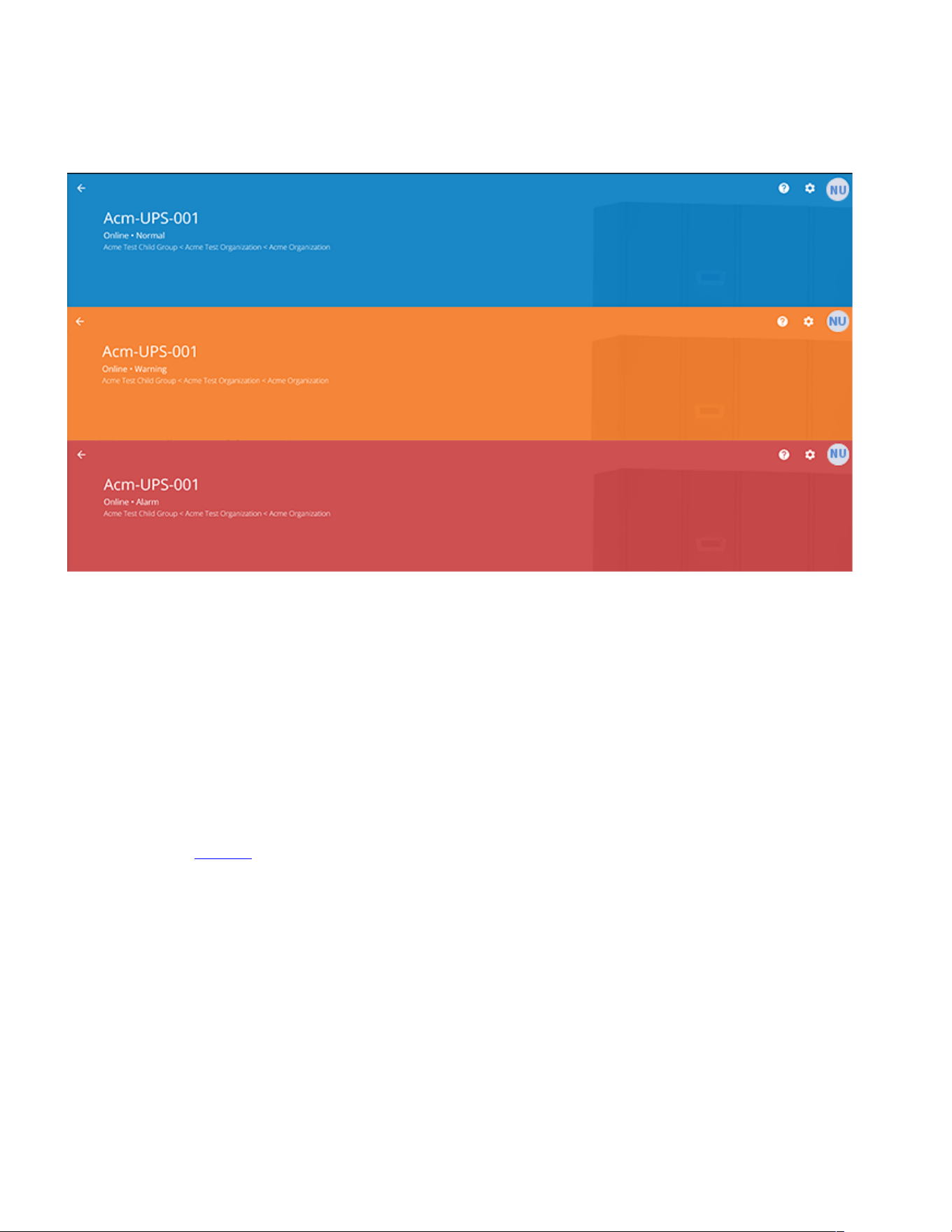
1. Device Summary Screen Banner- changes colors, indicating the different UPS operational modes.
• Blue- Online Normal Mode.
• Orange- Online Warning
• Red- Online Alarm
Organizational Summary Screen
34 Eaton Tripp Lite Series Cloud Connected UPS System User Guide 934927—Rev B
Figure 39. Device Summary Screen Banner
2. Tabs Menu:
• Summary- displays the Device Summary Screen.
• Timeline- provides an overall summary of events for the Device that can be exported into a .csv file.
• Documents-displays the Eaton Cloud-Connected User’s Guide and sales brochure files.
• Settings- general settings that can be set on the UPS.
3. Device control- provides limited control over the Device, such as turning the Device ON/OFF/CYCLE,
running a battery test.
4. Device details- displays an overview of the Device's operating status, trends, and properties.
5. Device load control- gives control over the output load segment(s) associated with the selected Device.
6. Timeline- displays active or inactive alarms and events that can be exported into a .csv format(see
Figure 63) .
7. Device Properties-provides the ability to edit or view the Device information.
8. Trends- displays specific UPS performance data that can be customized and downloaded over a 31-day
time interval.
Organizational Summary Screen
Eaton Tripp Lite Series Cloud Connected UPS System User Guide 934927—Rev B 35
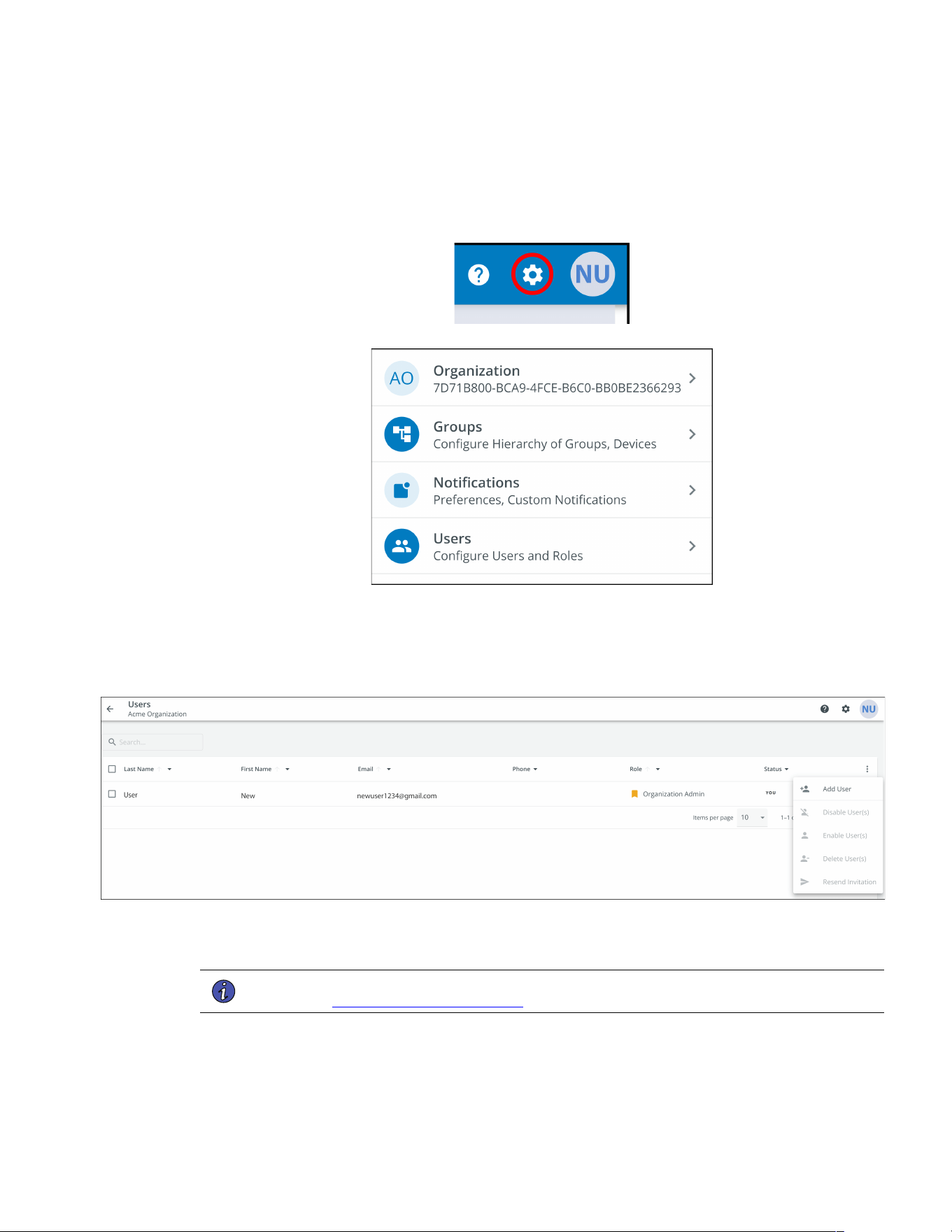
44..66 MMaannaaggiinngg UUsseerrss
The Users Management Screen allows the administrator or other users to add, invite, or remove inactive
members from an Organization.
To access the User Management Screen, click on the Settings Menu then Users (Configure Users and Roles).
To add a User, click on the three dots to the right of the page, then select Add User.
To delete or Enable/Disable/or Delete a User, select the User and then the three dots to being up the User
Management Menu.
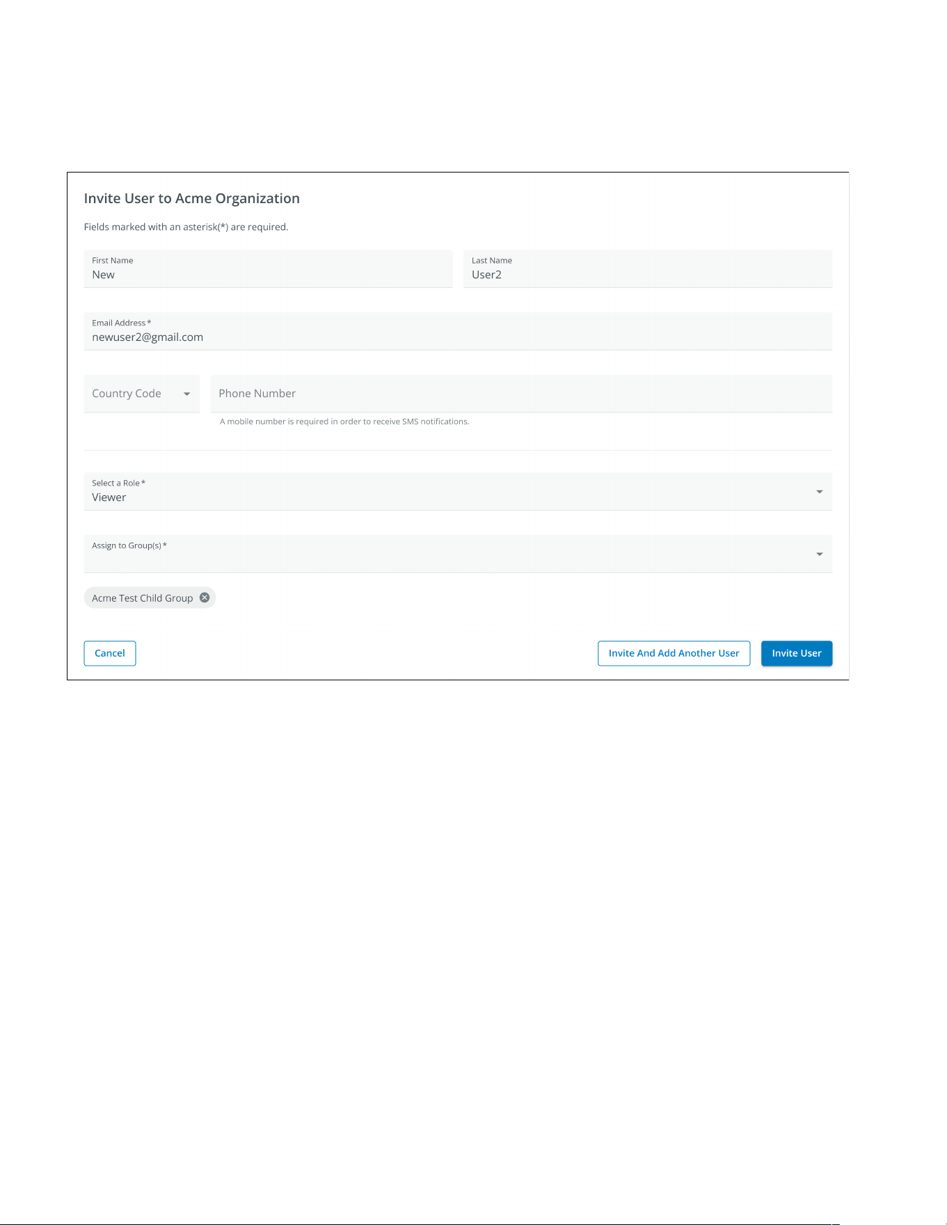
Fill out the User information. Then select the Invite User button. An email will be sent to invite the new User to
the Organization.
NOTE The new Users will have to set up an account if they do not have one. See
User Enrollment and Activation .
Managing Users
Eaton Tripp Lite Series Cloud Connected UPS System User Guide 934927—Rev B 37
44..77 CCrreeaattiinngg aa GGrroouupp WWiitthhiinn AAnn OOrrggaanniizzaattiioonn
1. Click on the Add a Group option on any one of the four areas on the summary screen.
Figure 41. Adding a Group
Creating a Group Within An Organization
38 Eaton Tripp Lite Series Cloud Connected UPS System User Guide 934927—Rev B
2. Enter in a name and then select the parent organization where the new Group will reside. Click Next.
Figure 42. Group Details
3. Move any existing Groups to the newly created Group (if applicable).
Figure 43. Move Groups
Creating a Group Within An Organization
Eaton Tripp Lite Series Cloud Connected UPS System User Guide 934927—Rev B 39
4. Assign users to the newly created Group.
Figure 44. Select Users
5. Choose between the default image or upload a new photo to help identify the Group. Click Add Group
when finished.
Figure 45. Display Preferences
Creating a Group Within An Organization
Eaton Tripp Lite Series Cloud Connected UPS System User Guide 934927—Rev B 41
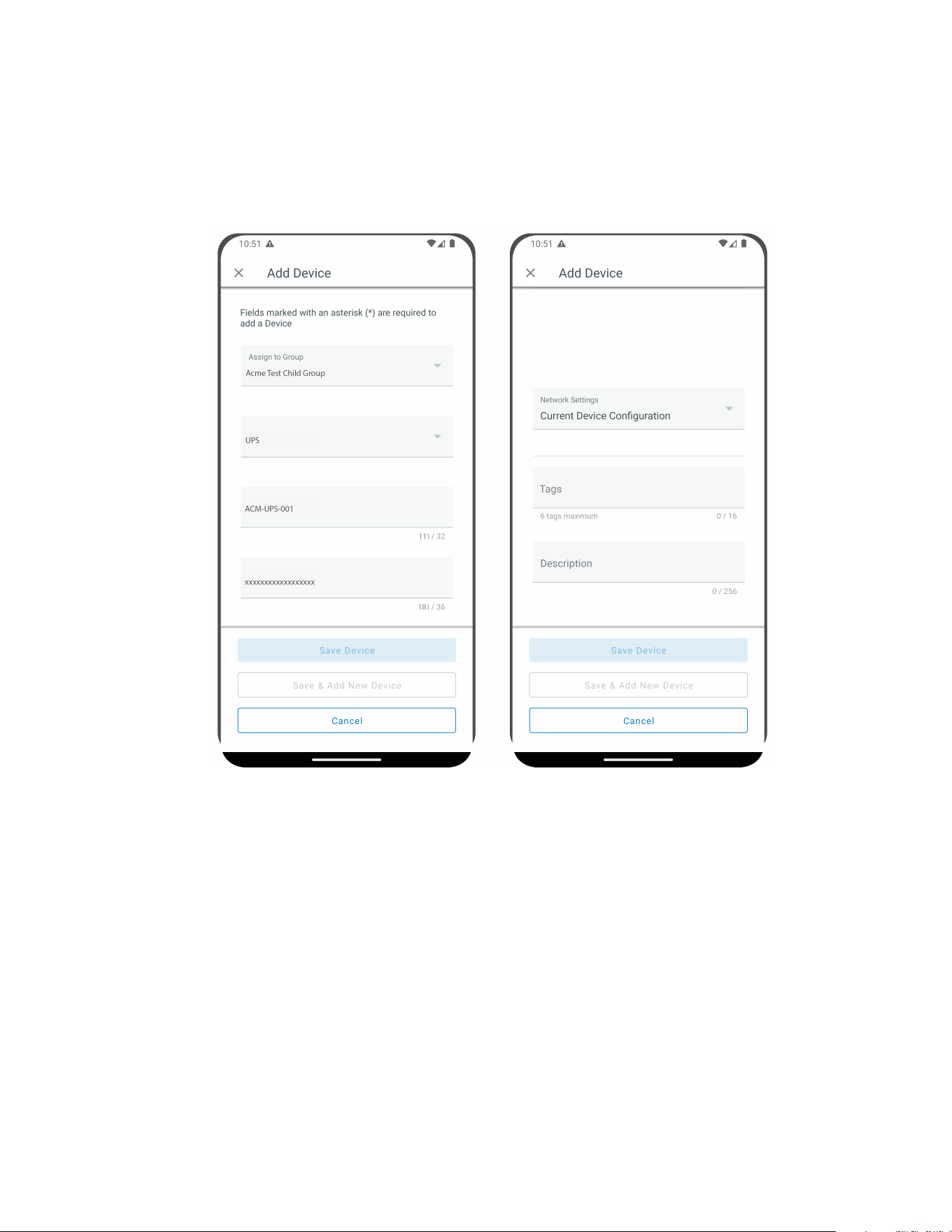
44..88 AAddddiinngg aa DDeevviiccee
Adding a Device Manually
1. Power the UPS ON and verify it is in Online Mode.
2. Connect an Ethernet cable (not supplied) from an active network connection to the port on the UPS.
3. Click on the organization or the group to which the device will be added in the Organizational Hierarchy
Menu.
4. Click one of the three areas of the Group Screen or in the Device Management Screen (see Figure 37).
Figure 47. Add Device Options
Adding a Device
Eaton Tripp Lite Series Cloud Connected UPS System User Guide 934927—Rev B 43
6. The device will now show that it is attached to the group or organization.
Figure 49. Organization Summary Screen
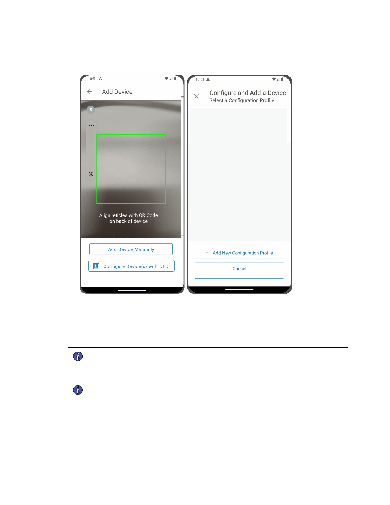
44..88..11 AAddddiinngg aa DDeevviiccee wwiitthh tthhee MMoobbiillee AApppplliiccaattiioonn
1. Download the Remote Monitoring Application and create an account or log into your existing account.
NOTE If the Remote Monitoring Application has been downloaded to the mobile device, the
QR code will automatically redirect to the add device screen within the Application. If it
was not previously downloaded, scanning the QR code will redirect the user to the app
store to download it and set up a user account.
2. Power the UPS ON and verify it is in Online Mode.
3. Connect an Ethernet cable (not supplied) from an active network connection to the port on the UPS.
4. Navigate to the Organizational Summary screen and click on devices.
5. Select the Add Device icon button.
6. Select OK to allow camera access.
Adding a Device
Eaton Tripp Lite Series Cloud Connected UPS System User Guide 934927—Rev B 45
8. Edit the Device Name, Tags, and Description. The Product ID, Serial Number, and GUID information will
automatically populate. Click Save Device.
Figure 51. Device Information
9. Check the Organizational Summary Screen within the Application to ensure the Device was successfully
added.
44..88..22 DDeevviiccee CCoonnffiigguurraattiioonn vviiaa NNFFCC
1. Power the UPS ON and verify it is in Online Mode.
2. Connect an Ethernet cable (not supplied) from an active network connection to the port on the UPS.
3. Scan the QR code label on the UPS with an NFC enabled smartphone or tablet device and create an
account if needed.
4. Navigate to the Eaton Remote Monitoring Organizational Summary Screen.
5. Select the Add Device icon button
Adding a Device
46 Eaton Tripp Lite Series Cloud Connected UPS System User Guide 934927—Rev B
Figure 52. Add and Configure Device
6. Click on Configure Device(s) with NFC.
7. Click on + Add New Configuration Profile.
8. Enter in a Configuration Profile Name.
9. Select the IPv4 Method, DHCP (Automatic) or Static.
NOTE If the IPv4 method selected is Static then the subnet mask and default gateway address
must be entered.
10. Set the Proxy IP address and the Proxy Port number.
NOTE An additional proxy user name and password may be required.
Adding a Device
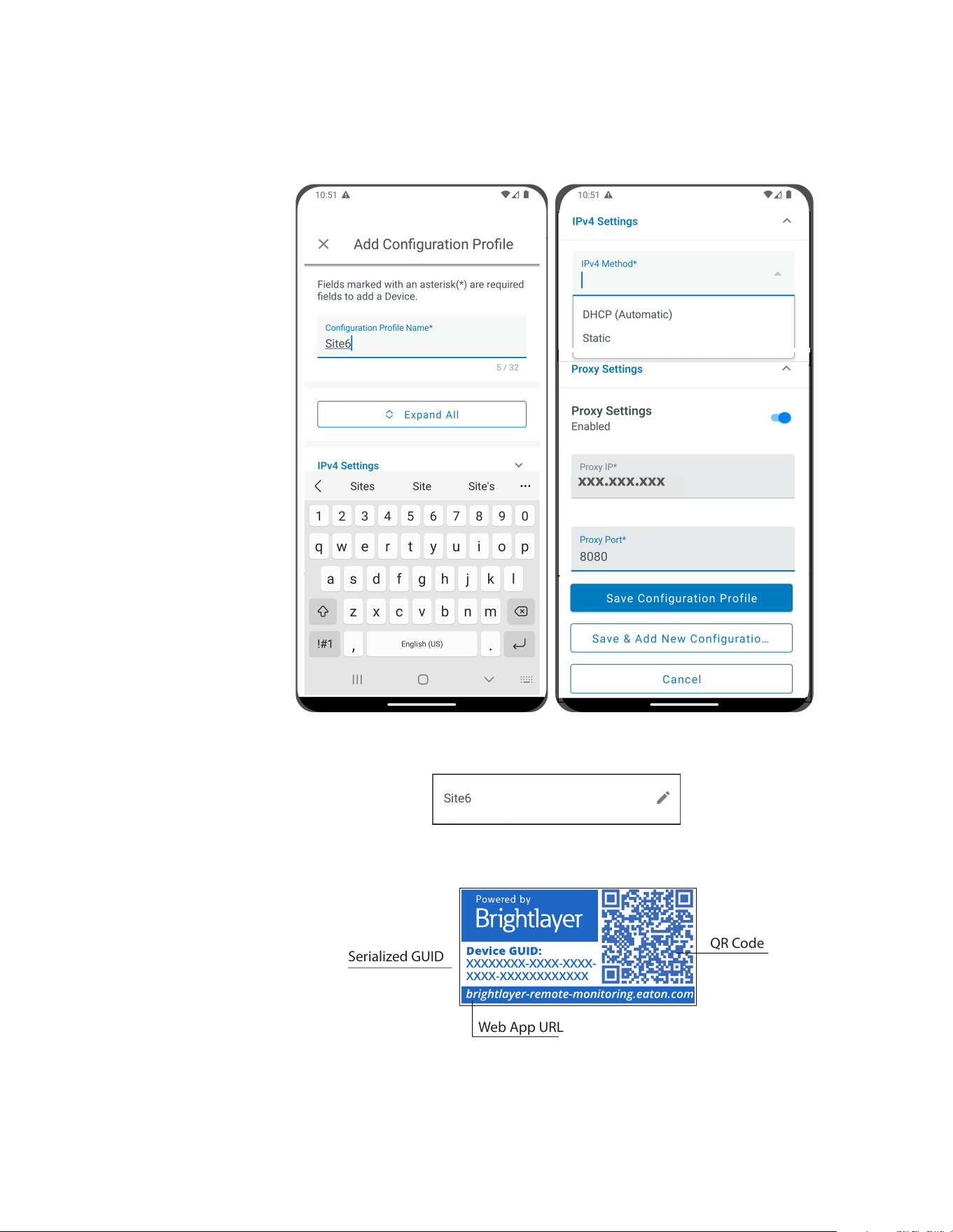
Eaton Tripp Lite Series Cloud Connected UPS System User Guide 934927—Rev B 47
11. Click Save Configuration Profile. The Profile is now saved and ready to apply to the UPS.
12. Select a NFC profile.
13. Scan the QR code on label of the UPS to obtain the GUID.
Serialized GUID
Web App URL
QR Code
Adding a Device
48 Eaton Tripp Lite Series Cloud Connected UPS System User Guide 934927—Rev B
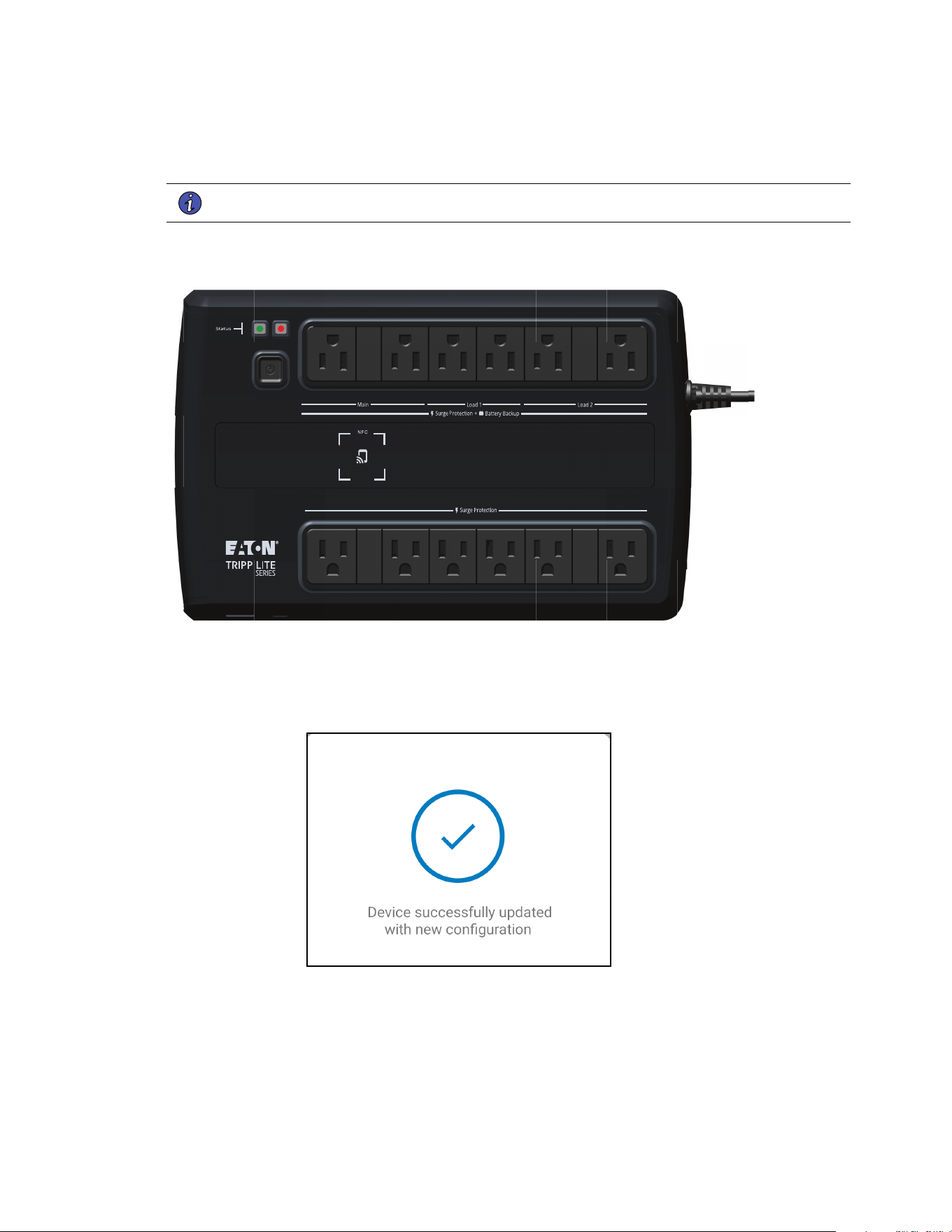
14. Align the phone with the NFC label location on the UPS. A popup will appear if the configuration is
updated. If there is a problem, an error popup will appear with the option to scan again.
NOTE The NFC label location may vary depending on the UPS model.
Figure 53. UPS NFC Label Location Example
15. The device is now updated with the configuration.
Figure 54. Application Update Success
Adding a Device
Eaton Tripp Lite Series Cloud Connected UPS System User Guide 934927—Rev B 49
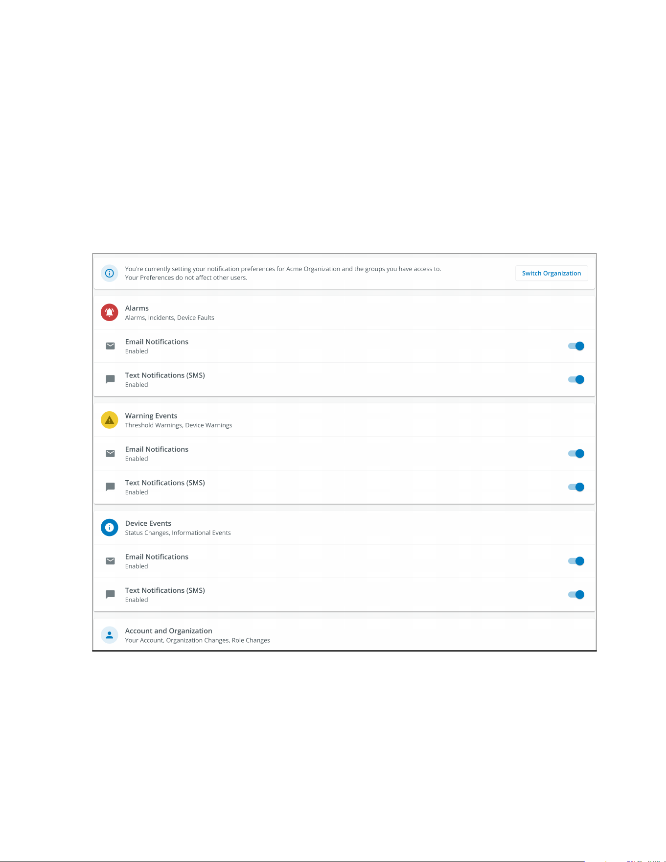
44..99 SSeettttiinngg AAlleerrttss aanndd NNoottiiffiiccaattiioonnss
The Notifications page allows a user to set up individual preferences for receiving notifications of device events
via email and SMS text messages.
Three categories of notifications can be enabled or disabled.
1. Alarms- Alarms, Incidents, Device Faults
2. Warning Events- Threshold Warnings, Device Warnings
3. Device Events- Status Changes, Informational Events
Figure 55. Preferences Notifications Screen
Setting Alerts and Notifications
50 Eaton Tripp Lite Series Cloud Connected UPS System User Guide 934927—Rev B
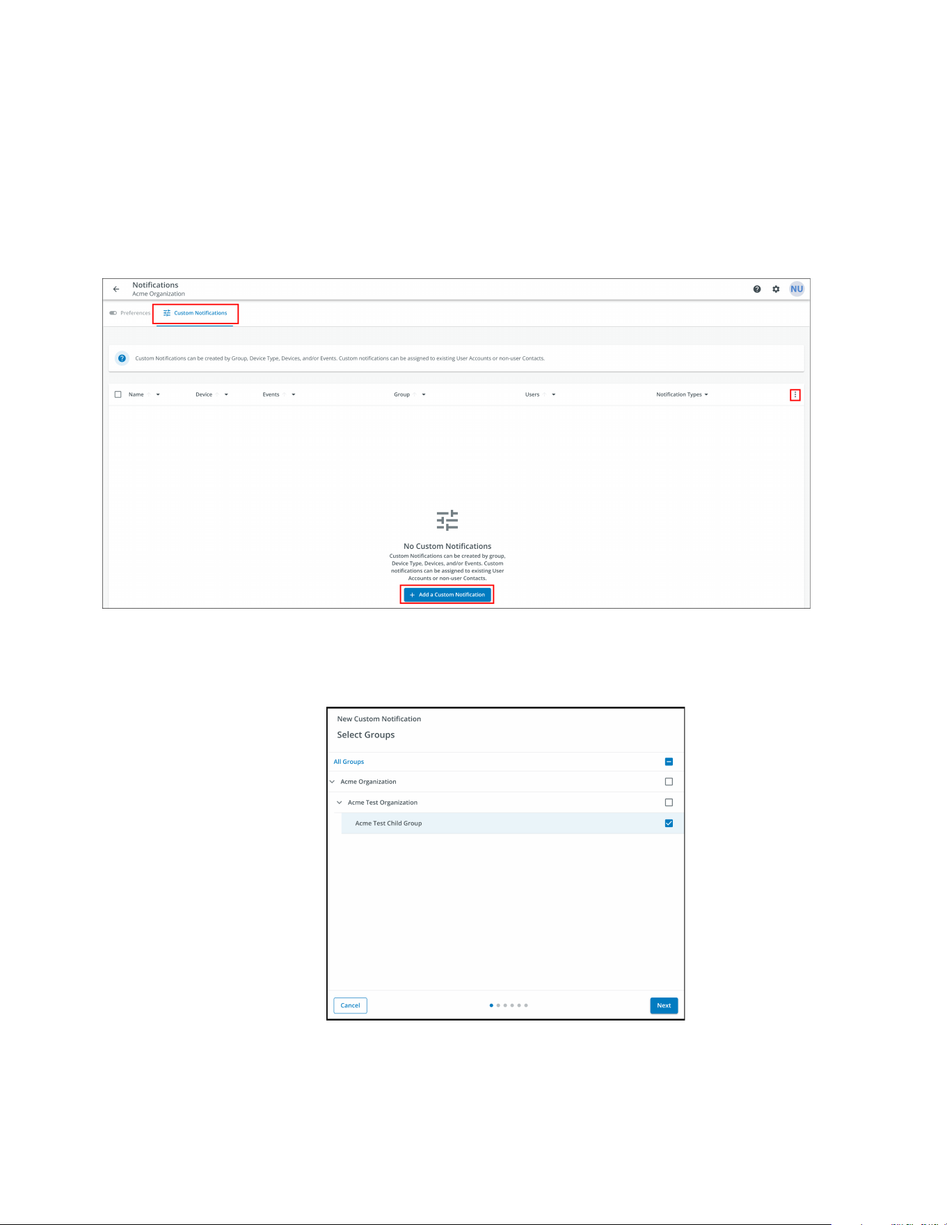
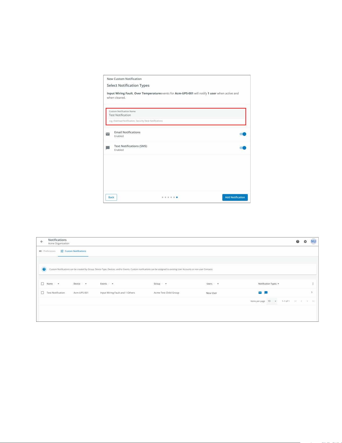
44..1100 SSeettttiinngg CCuussttoomm NNoottiiffiiccaattiioonnss
1. Click on Custom Notifications in the top left corner of the page.
2. Click on the Add Custom Notification button at the bottom of the page or the three dots on the right hand
side of the page to add a Custom Notification.
Figure 56. Add Custom Notification
3. Select the Group or Organization.
Figure 57. Select Groups
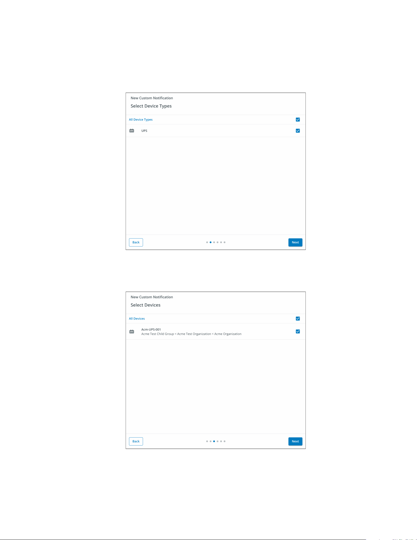
Setting Custom Notifications
52 Eaton Tripp Lite Series Cloud Connected UPS System User Guide 934927—Rev B
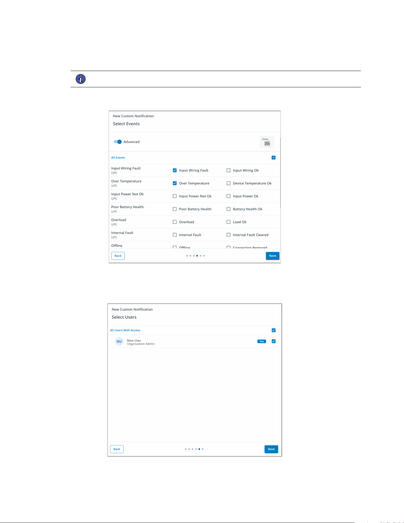
6. Select the specific event types for the notification.
NOTE Enable the Advanced feature in the top left corner to set a custom notification delay.
Figure 60. Select Event Types
7. Select the User that will receive the notifications.
Figure 61. Add Users
Setting Custom Notifications
Eaton Tripp Lite Series Cloud Connected UPS System User Guide 934927—Rev B 53
8. Give the Notification a name and enable email or text notifications. Click Add Notification.
Figure 62. Set Name of Notification
9. The notification is now created and active.
Figure 63. Custom Notification Success
Setting Custom Notifications
54 Eaton Tripp Lite Series Cloud Connected UPS System User Guide 934927—Rev B
CChhaapptteerr 55 UUPPSS MMaaiinntteennaannccee aanndd TTrroouubblleesshhoooottiinngg
55..11 BBaatttteerryy RReeppllaacceemmeenntt
Risk of electric shock. All repairs and service should be performed by QUALIFIED SERVICE PERSONNEL
ONLY. There are NO USER-SERVICEABLE PARTS inside the UPS. The battery circuit is not isolated from AC
Mains Input.
Replace the UPS battery with an Eaton-supplied battery ONLY! Ensure the UPS has been powered off and
safely isolated from AC input power before replacing the battery. Although the UPS may be disconnected from
the utility power, a hazardous voltage may still be present through the UPS battery. Use tools with insulated
handles.
Do not connect or disconnect the battery unless the area is known to be free of ignitable sources.
The battery in the UPS is rated for a 3–5 year service life. The length of service life varies, depending on the
frequency of use and ambient temperature. Batteries used beyond expected service life will often have
severely reduced runtimes. Replace batteries at least every five years to keep your UPS running at peak
efficiency.
Figure 64. AVR750UNC (AG-0786) Battery Replacement
Battery Replacement
Eaton Tripp Lite Series Cloud Connected UPS System User Guide 934927—Rev B 55
Safely secure the battery cables out of the way when removing and installing the battery so that they do not
get damaged during the battery replacement process. Use properly insulated tools when removing and
installing the battery.
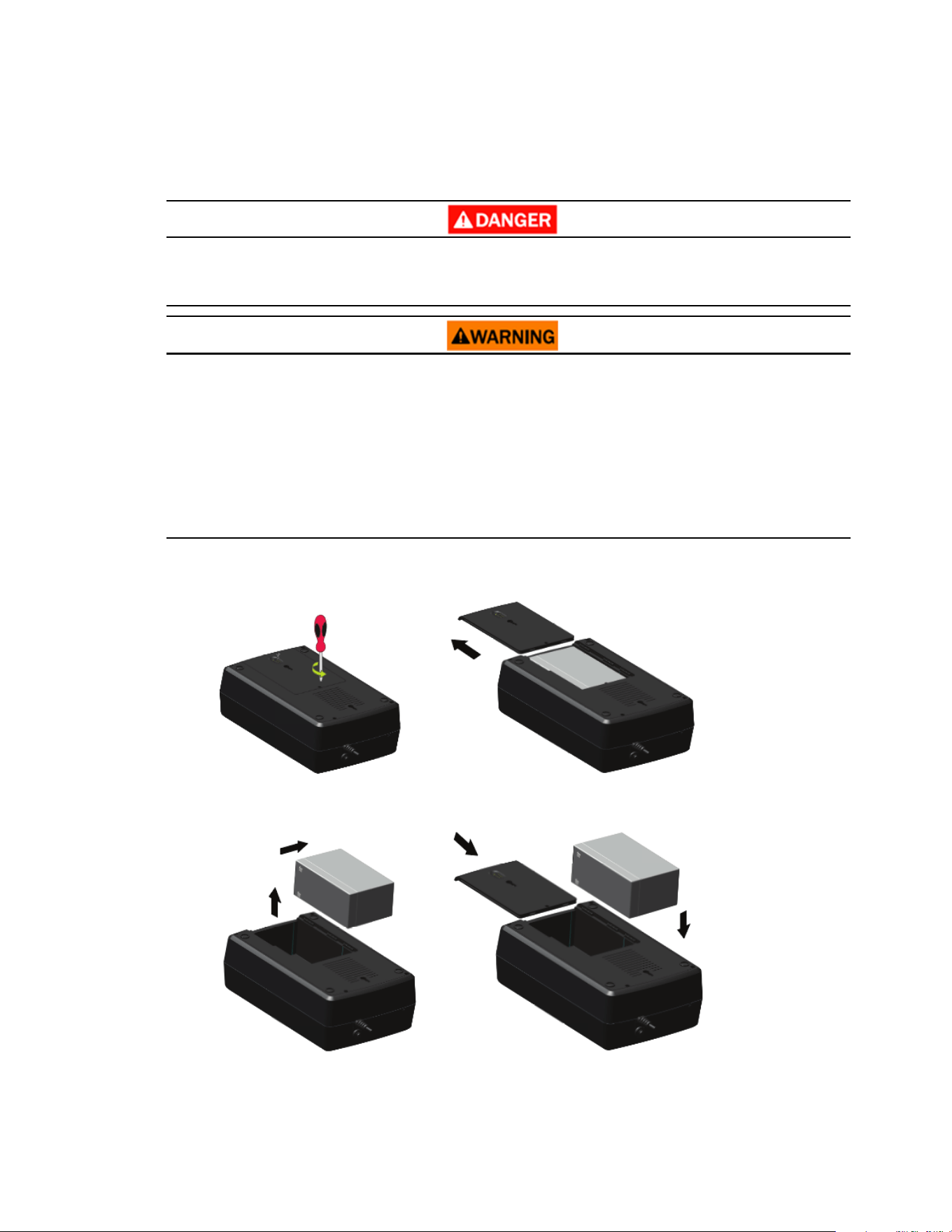
1. Remove the screw that holds the battery cover in place and set the screw aside in a safe place to avoid
dropping it inside the UPS, then remove the battery cover.
2. Gently slide the battery from the UPS to access the negative battery terminal and disconnect the wire
connected to the negative battery terminal.
3. Slightly pull the battery out to access the positive battery terminal and disconnect the wire from the
positive battery terminal.
4. Carefully remove the battery from the UPS.
5. Carefully slide the new battery into the UPS. Connect the battery wires firmly to the new battery terminals;
red to positive (+) followed by black to negative (–).
6. Slide the battery cover back onto the UPS and secure it with the battery compartment screw.
55..22 SSttoorraaggee
The ideal ambient temperature range is 5°F to 122°F (-15°C to 50°C). It is recommended to charge the UPS for
at least eight hours, then store the UPS covered and upright in a cool, dry location. Remove any accessories
and disconnect any cables connected to the UPS to avoid unnecessary draining of the battery.
EExxtteennddeedd SSttoorraaggee
During extended storage in environments where the ambient temperature is 5°F to 86°F (-15°C to 30°C),
charge the UPS battery every six months.
During extended storage in environments where the ambient temperature is 86°F to 113°F (30°C to 45°C),
charge the UPS battery every three months.
55..33 RReeccyycclliinngg UUsseedd EEqquuiippmmeenntt
Contact your local recycling or hazardous waste center for information regarding proper the disposal of used
equipment.
Danger: Dangerous voltage levels are present within the UPS. The UPS has an internal
power source (the battery). Consequently, the power outlets may be energized even if
the UPS is disconnected from the AC power source.
This symbol indicates that you should not discard the UPS or the UPS batteries in the
trash. This product contains sealed, lead— acid batteries and must be disposed of
properly. For more information, contact your local recycling/reuse or hazardous waste
center.
Special Symbols
The following are examples of symbols used on the UPS or accessories to alert you to important
information:
RISK OF ELECTRIC SHOCK - Observe the warning associated with the risk of
electric shock symbol.
CAUTION: REFER TO OPERATOR'S MANUAL - Refer to your operator's manual for
additional information, such as important operating and maintenance
instructions.
This symbol indicates that you should not discard the UPS or the UPS batteries
in the trash. This product contains sealed, lead‐acid batteries and must be
disposed of properly. For more information, contact your local recycling/reuse or
hazardous waste center.
This symbol indicates that you should not discard waste electrical or electronic
equipment (WEEE) in the trash. For proper disposal, contact your local
recycling/reuse or hazardous waste center.
Eaton, Powerware, and BladeUPS are registered trademarks of Eaton Corporation or its subsidiaries and affiliates.
Phillips and Pozidriv are registered trademarks of Phillips Screw Company.
ECopyright 2008–2010 Eaton Corporation, Raleigh, NC, USA. All rights reserved. No part of this document may be
reproduced in any way without the express written approval of Eaton Corporation.
This symbol indicates that you should not discard waste electrical or electronic
equipment (WEEE) in the trash. For proper disposal, contact your local recycling/reuse or
hazardous waste center for more information.
Storage
56 Eaton Tripp Lite Series Cloud Connected UPS System User Guide 934927—Rev B
55..44 TTrroouubblleesshhoooottiinngg
The Tripp Lite Series AVR750UNC UPS system has an audible alarm feature to alert you of potential power
problems. When activated, the alarm sounds at different intervals according to a particular condition. Use
Table 6 to determine and resolve the UPS alarms and conditions. See Table 2 for the various LED indicators and
alarms tones that can be active on the UPS.
Table 6. Troubleshooting
Problem Possible Cause Solutions
No LEDs are displayed on
the front panel
The UPS is not turned on
Verify that the UPS is connected to a valid power source and
press the power button again.
Battery Voltage is to too low Charge the battery for at least six hours.
Battery fault Replace the battery.
The UPS is always in
battery mode
The power cord is disconnected Verify that the UPS is connected to a valid power source.
The UPS alarm sounds
continuously
Overload in Line mode
Remove any unnecessary load and verify that the load does not
exceed the defined UPS specifications. If the problem persists,
contact Eaton support.
Output short fault
Disconnect the load. Check the equipment for potential issues.
Plug the devices back in, one at a time. If the problem persists,
contact Eaton support.
Overcharge fault
Disconnect the load. Check the equipment for potential issues.
Plug the devices back in, one at a time. If the problem persists,
contact Eaton support.
Backup time too short
Battery voltage is too low Charge the battery at least six hours.
Battery is defective Replace the battery.
Troubleshooting

Eaton Tripp Lite Series Cloud Connected UPS System User Guide 934927—Rev B 57
55..55 SSeerrvviiccee aanndd SSuuppppoorrtt
If you have any questions or problems with the UPS, call your Local Distributor or Eaton Support at one of
the following telephone numbers and ask for a UPS technical representative.
United States:
1–800–356–5737
Canada:
1–800–461–9166 ext 260
All other countries: Call your local service representative
Please have the following information ready when you call Eaton Support:
• Model number
• Serial number
• Version number (if available)
• Date of failure or problem
• Symptoms of failure or problem
• Customer return address and contact information
If repair is required, you will be given a Returned Material Authorization (RMA) Number. This number must
appear on the outside of the package and on the Bill Of Lading (if applicable). Use the original packaging or
request packaging from Eaton Support or your local distributor. Units damaged in shipment as a result of
improper packaging are not covered under warranty. A replacement or repair unit will be shipped, and freight
prepaid for all warrantied units.
NOTE For critical applications, immediate replacement may be available. Call Eaton Support
for the dealer or distributor nearest you.
Service and Support
58 Eaton Tripp Lite Series Cloud Connected UPS System User Guide 934927—Rev B
CChhaapptteerr 66 SSppeecciiffiiccaattiioonn
66..11 PPrroodduucctt SSppeecciiffiiccaattiioonnss
Table 7. Input Characteristics
AVR750UNC (AG-0786)
Capacity VA/Watts
750/450
Voltage AC
120 V
AC voltage range
89–145VAC
High line set 145V +/- 5%
High line reset 142V +/- 5%
Low line set 89V +/- 5%
Low line reset 92V +/- 5%
AC amps
10A
frequency
50 or 60 Hz +/- 5 Hz (default 60Hz)
AC input protection
(1) Thermal breaker 10A
Line efficiency at full load 98.4%(meets energy star 2.0)
Line efficiency at half load 98.4%(meets energy star 2.0)
Table 8. Output Characteristics
AVR750UNC (AG-0786)
Nominal output voltage
120V
AC amps out
6.3A
AC output voltage (Line
Mode)
120V (follows input voltage 89–145VAC)
AC output voltage (Battery
Mode)
120V +/- 10%
Output AC waveform (Line
Mode)
Sine wave
Output AC waveform
(Battery Mode)
Sine wave
Frequency
50 or 60 Hz follows the AC input frequency
Battery cold start is 60Hz only
Transfer time AC to DC
4 ~ 6 ms (Max < 10 ms)
Product Specifications
Eaton Tripp Lite Series Cloud Connected UPS System User Guide 934927—Rev B 59
Table 9. Protection Characteristics
AVR750UNC (AG-0786)
UPS AC suppression joule
rating
316 (AC)
UPS AC suppression
response time
Instantaneous
Overload protection
Line Mode Overload Alert Condition - 110%±10%, goes to fault after 5 minutes; Overload Fault
Condition - 120%±10%, goes to fault immediately
Battery Mode Overload Alert Condition - 110%±10%, shuts down in 5 seconds; Battery Mode
Overload Fault Condition - 120%±10%, shuts down immediately
Table 10. Battery Characteristics
AVR750UNC (AG-0786)
Battery type
Sealed, maintenance-free, lead acid batteries.
Battery voltage / AH Qty (1) 12V / 9AH
Battery charge current
1A (1.5A Max)
Battery float voltage
13.7 VDC
Recharge time 8 hours From 10% to 90% capacity
Backup time
3 minutes at full load
11 minutes at half load
Low voltage shutdown
voltage
9.6V all load levels
Min voltage for cold start
10.6V
Hot-swappable battery
No
Table 11. Environment
AVR750UNC (AG-0786)
Humidity 0-90% RH @ 0-40 C (non-condensing)
Storage temperature
-15 to +50 ℃
Operating temperature
0 to +40 ℃
Operating elevation
0-2000 meters
Table 12. Weights and Dimensions
AVR750UNC (AG-0786)
Net Weight, lb. (kg) 17 lbs (7.3 kg)
H x W x D, in. (cm) 4.0 × 7.4 × 12 (10.6 × 19.0 × 30.5)
Product Specifications
60 Eaton Tripp Lite Series Cloud Connected UPS System User Guide 934927—Rev B
Table 13. Standards and Compliance
AVR750UNC (AG-0786)
Product certifications
CSA C22.2 NO. 107.3 (CAN); UL1778 (US) ; NOM (Mexico)
Compliance Energy Star; ROHS; FCC Class A, DOE
Table 14. Electrical Input Connections
AVR750UNC (AG-0786)
Line cord
5ft NEMA 5–15P ; straight plug
Table 15. Electrical Output Connections
AVR750UNC (AG-0786)
Receptacle quantity and
type
Qty (6) battery and surge protected 5–15 outlets, with two switched outlet groups
Quantity two main 5–15 outlets
Quantity four switched 5–15 outlets
Quantity six surge-only protected 5–15 outlets
Product Specifications

934927B
934927 B