
INSTRUCTION MANUAL FOR USE
SPIRAL MIXER
MOD.
SK - RTF - RTS - SKV - RTSV
English
DICHIARAZIONE DI CONFORMITÀ
DECLARATION OF CONFORMITY / KONFORMITÄTSERKLÄRUNG / DECLARATION CE DE CONFORMITEE
/
DECLARACIÓN DE CONFORMIDAD CE
IT: Io sooscrio, rappresentante il seguente costruore:
EN: The undersigned, represenng the following manufacturer:
DE: Der Unterzeichner, der den nachstehenden Hersteller vertri:
FR: Le soussigné, représentant le fabricant suivant:
ES: Yo, abajo rmante, en representante y fabricante:
IT: ha incaricato la persona autorizzata a costuire e conservare il fascicolo tecnico è il fabbricante stesso:
EN: authorized the person authorized to compile and store the technical le:
DE: hat die dazu befugte Person mit der Erstellung und Auewahrung der folgenden technischen Unterlagen beauragt:
FR: a chargé la personne autoriséèe à constuer et à garder le dossier technique:
ES: instruí a la persona facultada para elaborar y mantener el expediente técnico:
IT: Il sottoscritto costruttore dichiara che i modelli di impastatrice con vasca rotativa utilizzata per amalgamare i vari ingredienti:
EN: The undersigned as a manufacturer, declares that the models of spiral mixer:
DE: Der unterzeichnende Hersteller erklärt, dass die Modell der teigknetmaschinen:
FR: Le fabricat soussigné déclare que les modèles de électrique pétrins à spiral:
ES: El abajo firmante declara como fabricante que los modelos amasadora de espiral:
MODELLI / MODELS
SK RTF RTS SKV RTSV
SK10MO - SK10MO2V
- -
SKV10MO
-
SK15MO - SK15TR - SK15MO2V - SK15TR2V
- -
SKV15MO
-
SK20MO - SK20TR - SK20MO2V - SK20TR2V RTF20MO - RTF20TR - RTF20MO2V - RTF20TR2V RTS20MO - RTS20TR - RTS20MO2V - RTS20TR2V SKV20MO RTSV20MO
SK30MO - SK30TR - SK30MO2V - SK30TR2V RTF30MO - RTF30TR - RTF30MO2V - RTF30TR2V RTS30MO - RTS30TR - RTS30MO2V - RTS30TR2V SKV30MO RTSV30MO
SK40MO - SK40TR - SK40MO2V - SK40TR2V RTF40MO - RTF40TR - RTF40MO2V - RTF40TR2V RTS40MO - RTS40TR - RTS40MO2V - RTS40TR2V SKV40MO RTSV40MO
SK50MO - SK50TR - SK50MO2V - SK50TR2V RTF50MO - RTF50TR - RTF50MO2V - RTF50TR2V RTS50MO - RTS50TR - RTS50MO2V - RTS50TR2V SKV50MO RTSV50MO
IT: sono conformi a tutte le disposizioni legislative pertinenti previste dalle seguenti direttive comunitarie (comprese tutte le modifiche applicate):
EN: are conformed to the following CE laws (including all applicable amendments):
DE: allen betreffenden Rechtsvorschiften entspricht, die von den folgenden EU-Richtlinien (einschließlich aller angewandten Änderungen):
FR: ils sont conforme à toutes les normatives pertinentes aux suivantes directives CE (inclus tous changements appliqués):
ES: Y cuando cumplan con las siguientes leyes de la UE (incluyendo todas las modificaciones aplicables):
2006/42/CE IT: Direva Macchine - EN:Machinery Direcve - FR:Direcve Machines - DE:Maschinenrichtlinie - ES:Direcva de Máquinas
2014/35/UE IT: Direva Bassa Tensione - EN:Low Voltage Direcve - FR:Direcve Basse Tension - DE:Niederspannungsrichtlinie - ES:Direcva de Baja Tensión
2014/30/UE IT: Direva Compabilità Eleromagneca - EN:Electromagnec Compability Direcve - FR:Direcve Compabilité
Electomagnéque - DE:EMV-Richtlinie - vorgesehen sind - ES:Direcva de Compabilidad Electromagnéca
2011/65/UE IT: Direva RoHS - EN:RoHS Direcve - FR:Direcve RoHS - DE:RoHS-Richtlinie - ES:Direcva RoHS
1935/2004 IT: Regolamento riguardante i materiali e gli ogge desna a venire a contao con prodo alimentari
EN: Regulaon on materials and arcles intended to come into contact with food
FR: Règlement concernant les matériaux et objets desnés à entrer en contact avec des denrées alimentaires
DE: Verordnung über Materialien und Gegenstände, die dazu besmmt sind, mit Lebensmieln in Berührung zu kommen
ES: Reglamento sobre los materiales y objetos desnados a entrar en contacto con alimentos
IT: e inoltre dichiara che sono state applicate le seguenti norme armonizzate:
EN: and also declares that have been applied the following harmonized rules:
DE: und erklärt ebenfalls, welche angewandten folgende harmonisierten Normen benutzt warden:
FR: et déclare également qui ont été appliquées les normes harmonisées suivantes:
ES: e incluso que se han aplicado para declarar las siguientes normas armonizadas:
norme armonizzate di tipo “A” / harmonized rules type “A” / hormonisierten Normen typ “A” / normes harmonisées de type “A”/ normas armonizadas de tipo “A”
UNI EN ISO 12100:2010
norme armonizzate di tipo “C” / harmonized rules type “C” / hormonisierten Normen typ “C” / normes harmonisées de type “C” / normas armonizadas de tipo “C”
UNI EN 453:2014
IT: Firma del legale rappresentante
EN: Authorized Signature
DE: Rechtsverbindliche Unterschri
FR: Signature autorisée
ES: Firma del Representante Legal
________________________
________ :
__ / __ / _____
AMPTO, INC
8409 NW 68th Street, Miami, FL 33166
Tel: +1 (877)-992-6211 ext. 303
Fax: +1 (305) 960-7796
www.ampto.com
AMPTO, INC
8409 NW 68th Street, Miami, FL 33166
Tel: +1 (877)-992-6211 ext. 303
Fax: +1 (305) 960-7796
www.ampto.com

English
SPIRAL MIXER
SK - RTF - RTS
SKV - RTSV
0.0
32
WARRANTY
All component parts, equipment, excluding electrical parts, have a warranty of 12 months, provided that the defects
are due to the construcon. The shipment of the pieces in queson will be COD. Parts replaced under warranty will
be invoiced; upon receipt of the pieces (returned free port), which was requested replacement, we will provide with a
credit note. The warranty does not cover the replacement of the machine. The warranty does not cover labor charges
for replacement of parts and any other addional expenses.
SHIPMENTS
The goods travel at the risk of the customer. Any complaints on the bad condion of the material should be shown to
the carrier at the me of Uploading. Please give due consideraon to what the subject of the liability of the carrier and
the mandatory nature of the highlight of any damage at the me of Uploading. We underline that our company is not
liable for damage not idened to the carrier at the me of collecon of the goods, even if the same was forwarded
free port debit invoice.
JURISDICTION
Any dispute is referred to the court with territorial jurisdicon of the oce of the manufacturer.
INDEX
FOREWORD
1.1. Purpose of the manual 33
1.2. How to read the user manual 33
1.3. Storing the manual 34
1.4. Updang the manual 34
1.5. Recipients 34
1.6. Glossary and symbols 34
GENERAL INFORMATION
2.1. Idencaon data of the manufacturer 36
2.2. Idencaon data and machine data plate 36
2.3. Tests conducted before delivery 36
2.4. Intended use and construcon parts 36
2.5. Use condions 37
2.6. Set-up responsibilies of the customer 37
2.7. Technical data 37
2.8. Machine dimensions mod. SK 39
2.9. Machine dimensions mod. RTF - Spiral mixers with rising top 39
2.10. Machine dimensions mod. RTS - Spiral mixers with rising top and
extractable bowl 39
2.11. Machine dimensions mod. SKV - Spiral mixers with variable speed 39
2.12. Machine dimensions mod. RTSV - Rising head spiral mixers with
variable speed 39
INSTALLATION
3.1. Transport and handling 40
3.2. Storage 40
3.3. Checks upon receipt 40
3.4. Unpacking 41
3.5. Liing the machine 41
3.6. Idencaon of the components 42
3.7. Idencaon of the machine 42
3.8. Assembling the wheels 42
3.9. Machine posioning and stability 43
3.10. Power supply 44
3.11. Checking the electrical conneco 45
3.12. First start-up 45
SAFETY
4.1. Safety instrucons 46
4.2. Safety devices 46
4.3. Operator zones 46
4.4. Normal use, improper use, prohbited use 47
4.5. Warnings on residual risks 47
4.6. Residual risks 47
USE OF THE MACHINE
5.1. Control panel 49
5.2. Commissioning spiral mixer Mod. SK, RTF, RTS 49
5.3. Stop 50
5.4. Switching o 50
5.5. Operaon safety 50
5.6. No voltage 50
5.7. Opening the mobile guard 50
5.8. Removing the tank (where provided) 50
5.9. Components idencaon mod. SKV e RTSV 51
5.10. Replacement of mixing tools RTSV 51
5.11. Commissioning spiral mixer mod. SKV, RTSV 51
5.12. Control panels SKV and RTSV mixer with variable speed 52
5.13. Set-up mixers SKV, RTSV 52
MAINTENANCE
6.1. Requisites of the maintenance technician 53
6.2. Maintenance prescripon 53
6.3. Roune maintenance intervenon 54
6.4. Scheduled maintenance intervenon 54
6.5. Check list - Roune maintenance 56
6.6. Check list - Scheduled maintenance 56
6.7. Check list - Scheduled component replacement 57
6.8. Troubleshoong 57
6.9. Cleaning 58
SCRAPPING, DEMOLITION AND DISPOSAL
7.1. Scrapping 59
7.2. Demolion 59
7.3. Disposal 59
WIRING DIAGRAMS
8.1. SK & RTF 230/1 V - 50 Hz 144
8.2. SK & RTF 400/3 V - 50 Hz 145
8.3. RTS 230/1 V 146
8.4. RTS 400/3 V - 50 Hz 146
8.5. RTS - 400/3 V - 50 Hz 147
8.6. SKV-RTSV - 230/1 V - 50 Hz MONOFASE 147
English
SPIRAL MIXER
SK - RTF - RTS
SKV - RTSV
1
0.0
33
1 0.0 1
1.1. PURPOSE OF THE MANUAL
This User Manual is an integral part of the Machine and it provides the informaon required to:
• Sensise the operators to safety issues;
• Handle the machine (with or without packaging) under safe condions;
• Install the machine correctly;
• Know its operaons and limits;
• Use it under safe condions;
• Perform maintenance safely and correctly;
• Dismantle the machine under safe condions and in compliance with the occupaonal standards in force.
According to the naonal standards in force, the managers of the departments in which the machine is to be
installed must carefully read this document and make the operators and maintenance technicians read the
parts relave to their eld of experse.
The me spent doing this will be rewarded by the eciency of the machine and its use under safe condions.
The plants where the machine is to be installed must comply with the occupaonal standards in force.
The instrucons, drawings, and documents contained in this Manual constute proprietary and condenal informaon and they
cannot be reproduced either in whole or in part.
Moreover, in the event the manufacturer applies modicaons to this document, the customer must make sure that only the updat-
ed versions of the manual are available.
1.2. HOW TO READ THE USER MANUAL
This manual is divided into chapters, each one refers to a specic operator funcon (INSTALLER, OPERATOR OR MAINTENANCE
TECHNICIAN) and denes the experse required to run the machine under safe condions.
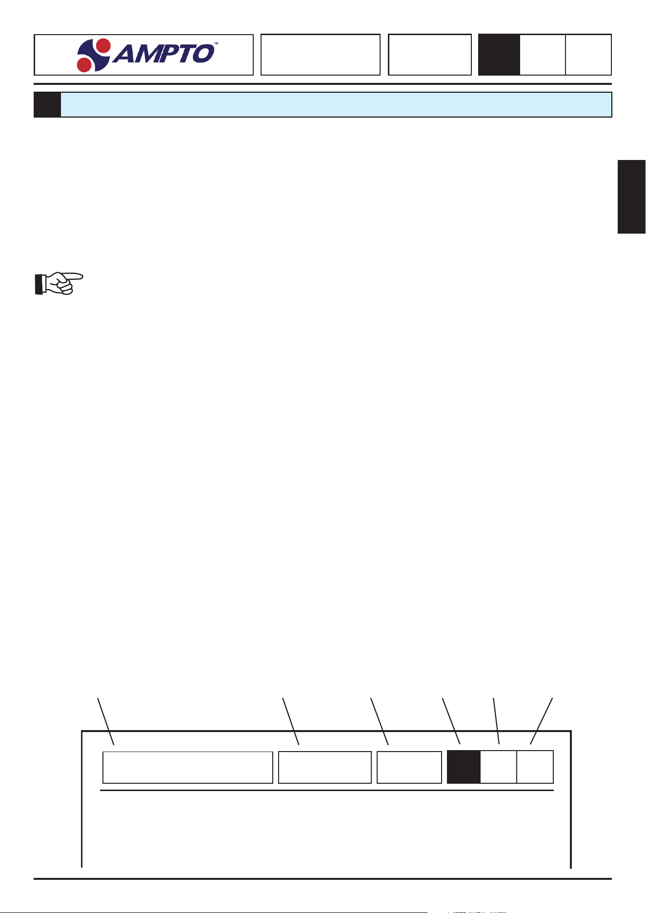
The User Manual consists of a cover, index, and a series of chapters.
The inial page provides the idencaon data for the machine and model, the revision of the user manual, and a photo/drawing
of the described machine to facilitate the idencaon of the machine and of the relave manual.
The rst page of the index shows the table of revisions of the user manual and of its parts, which correlates the revision level of the
manual to that of the index and chapters.
PAGE EXAMPLE
Company Logo Machine Name Model n° Chapter Rev. n° Page
FOREWORD
1

English
SPIRAL MIXER
SK - RTF - RTS
SKV - RTSV
1
0.0
34
1.3. STORING THE MANUAL
The user manual must be stored carefully and must be remain with the machine unl its disposal.
Handle the user manual with care, with clean hands and do not place it on dirty surfaces.
Parts must not be removed, torn, or be arbitrarily modied.
The manual must be stored in an environment protected against humidity and heat and in the proximity of the machine.
Upon request, the manufacturer may provide addional copies of the user manual.
1.4. UPDATING THE MANUAL
The manufacturer reserves the right to modify the project and improve the machine without prior noce and without updang the
manual delivered to the user.
The manufacturer is liable for the descripons provided in Italian. Any translaon cannot be fully veried; therefore, refer to the
Italian version if any inconsistency is detected.
1.5. RECIPIENTS
This user manual is addressed to the installer, operator, and qualied maintenance personnel.
The term “OPERATOR” refers to the personnel in charge of running, adjusng, cleaning and performing roune maintenance on the
machine.
The term “MAINTENANCE TECHNICIAN” refers to those persons who have aended specialist courses, training courses, etc. and
have experience in installing, commissioning, repairing, and transporng the machine.
The term “EXPOSED PERSON” is anyone standing within and/or near the machine area pung his safety and health at risk.
Qualicaon of the recipients
The machine is intended for industrial and professional use; therefore it can be used only by qualied personnel, in parcular by
those who:
• Have reached an appropriate age;
• Are physically and psychologically suitable for performing technically dicult operaons;
• Have been trained on how to use and perform maintenance on the machine;
• Have been judged suitable by the employer for performing the tasks assigned.;
• Are able to understand and interpret the operator manual and safety provisions;
• Are familiar with the emergency procedures and knows how to implement them:
• Are able to acvate the specic type of equipment;
• Are familiar with specic standards;
• Have understood the operang procedures provided by the manufacturer of the machine.
1.6. GLOSSARY AND SYMBOLS
This paragraph lists uncommon terms.
Below are the abbreviaons and symbols used with their meanings and descripons. Both the abbreviaons and symbols provide,
quickly and unambiguously, the informaon required to use the machine correctly and under safe condions.
DANGER ZONE: Means any zone within and/or around machinery in which a person is subject to a risk to his health or safety
(Annex I, 1.1.1. Direcve 98/37/EC).
EXPOSED PERSON: Means any person wholly or parally in a danger zone (Annex I, 1.1.1. Direcve 98/37/EC).
OPERATOR: Means the person or persons installing, operang, adjusng, maintaining, cleaning, repairing or moving machinery.
English
SPIRAL MIXER
SK - RTF - RTS
SKV - RTSV
1
0.0
35
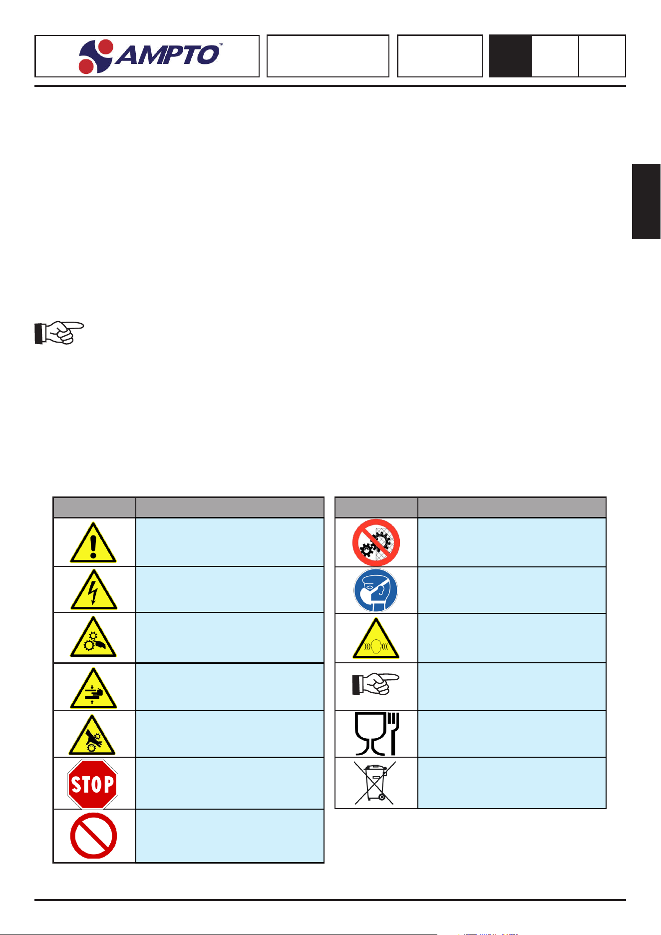
Symbol Name
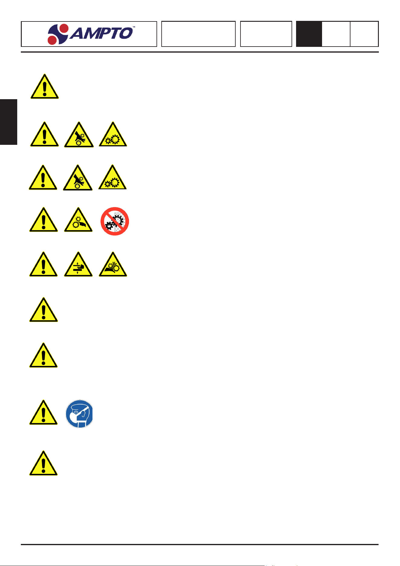
Do not remove the safety devices
Respiratory protecon device
Noise
Precauon
Food machinery
WEEE
MAN-MACHINE INTERACTION: Any situaon in which the operator interacts with the machine in any operang phase and in any
moment of the machine duraon.
OPERATOR QUALIFICATION: Minimum level of experse that the operator must have to perform the described operaon.
MACHINE STATUS: Means the operaon mode (start, stop, etc.) and the condion of the safety devices installed on the machine.
RESIDUAL RISK: Hazard, which cannot be eliminated or reduced during the design phase and against which the protecon
devices are not (or not fully) eecve. The manual provides the informaon that proves its existence and the instrucons and
warnings to solve them (see, 5.5 and 5.5.1 of European standards EN 292/1 and EN 292/2)
SAFETY COMPONENT: Is a component used to guarantee safety and prevent failure or malfuncon that may aect the safety
and/or health of the exposed persons.
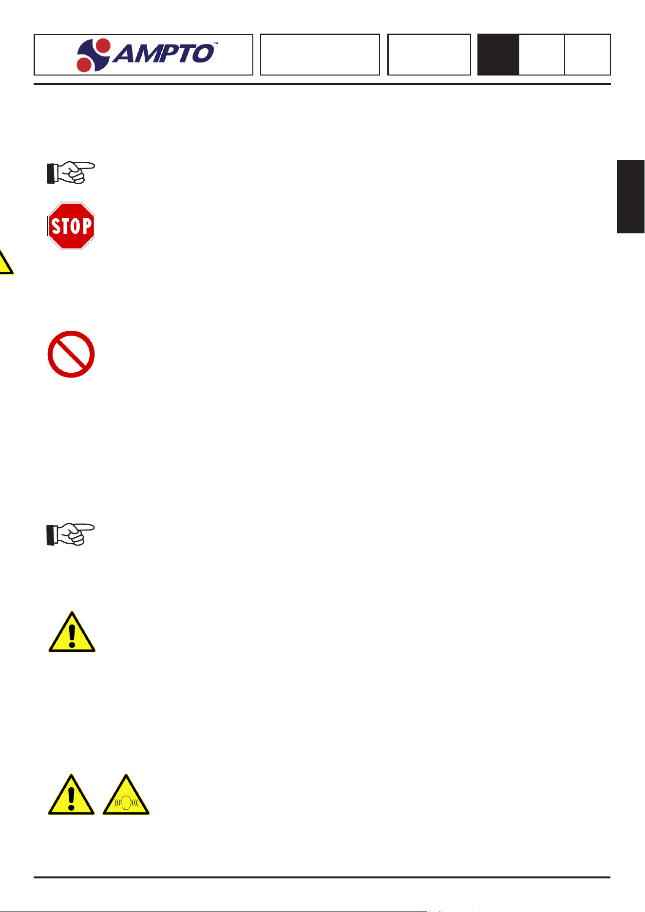
SYMBOLS
The descripons before this symbol contain
very important safety informaon/provisions. Failure to comply with this symbol
may result in:
• danger for the operators;
• loss of the warranty;
• manufacturer’s liability disclaimer.
SAFETY-RELATED SYMBOLS
• The symbols contained in a triangle indicate DANGER.
• The symbols contained in a circle indicate OBLIGATION/PROHIBITION.
Symbol Name
General Hazard
Dangerous voltage
There are dangerous mobile elements
in moon when xed guards are
removed
Risk of crushing the upper limbs
Entanglement
Stop
Prohibited

English
SPIRAL MIXER
SK - RTF - RTS
SKV - RTSV
2
0.0
36
GENERAL INFORMATION
2
2.1. IDENTIFICATION DATA OF THE MANUFACTURER
2.2. IDENTIFICATION DATA AND MACHINE DATA PLATE
The machine is equipped with an idencaon plate, which provides the following data:
2.3. TESTS CONDUCTED BEFORE DELIVERY
Before delivery, the machine undergoes safety and operaonal tests at the manufacturer’s premises in compliance with the standards
in force. Moreover, all the installed components undergo strict visual and instrumental tests.
2.4. INTENDED USE AND CONSTRUCTION PARTS
The machine is designed to mix so dough made with our, salt, yeast, fats, liquids (water, eggs, ..) potatoes and minced meat and
other food ingredients.
The machine consists of the following components:
1. The tank contains the food products to be mixed and it is placed on the front area of the machine to which it is xed; the tank
turns mechanically clockwise and it is started by an electric motor.
2. The dough tool, placed on the machine head, turns inside the spiral-shaped tank. Gears controlled by the electric motor turn
the tool mechanically.
3. Kneader rod consisng of a xed metal rod mounted on the head of the machine.
4. Interlocked mobile guard, which covers the upper part of the moving tank. It stops the dangerous mobile elements when it is
opened.
5. The machine consists of a bearing structure, which supports and contains the components of the motor, transmission and
control devices.
• The single-phase or three-phase electric motors can have one or more speeds.
• All the machine parts intended to come into contact with food products, such as the tank, tools, kneader rod, etc. are made of
stainless steel.
The machine supplied and described in this user manual is manufactured with the parts indicated in the CE declaraon of conformity.
FAC SIMILE
AMPTO, INC
8409 NW 68th Street, Miami, FL 33166
Tel: +1 (877)-992-6211 ext. 303
Fax: +1 (305) 960-7796
www.ampto.com

English
SPIRAL MIXER
SK - RTF - RTS
SKV - RTSV
2
0.0
37
2.6. SET-UP RESPONSIBILITIES OF THE CUSTOMER
A) Seng up the installaon site.
• The customer must set up a support surface for the machine as indicated in the use condion table.
B) Seng up the electrical system.
• The electric system must comply with the standards in force and must be provided with an ecient earthing system.
• Place an omnipolar disconnecng device on the power supply line, upstream of the machine.
• The power cables must be sized according to the maximum current required by the machine so that the total voltage drop, at
full load, is less than 2%.
If the power cable is damaged, it must be replaced by the manufacturer or its technical assistance service or in any case by a person
with similar qualicaons, in order to prevent any risk.
2.7. TECHNICAL DATA
2.5. USE CONDITIONS
DATA SK10/20/30/40/50 ** Serie TR/MO/2V
TRF20/30/40/50 ** Serie TR/MO/2V
RTS20/30/40/50 ** Serie TR/MO/2V
SKV10/15/20/30/40/50 ** Serie MO
RTSV20/30/40/50 ** Serie MO
Equivalent connuous A-weighted sound
power level
Lower than 70 Dba
Current nature - Frequency Cfr. machine idencaon plate
Current value Cfr. machine idencaon plate
Rated voltage Cfr. machine idencaon plate
Rated condional prospecve short-cir-
cuit current
6 kA Symmetrical
Earth and neutral TT e TN
Protecon rang IP 21
Machine posion Work bench used in the food industry, with height ranging between 900 and 1000
mm from the oor, in which it is possible to move around the machine with a free
space of at least 800 mm
Place of use Indoors
Maximum room temperature + 40° Degrees
Minimum work environment lighng 500 lux
Addional use condion "Machine NOT SUITABLE to run in environments containing contaminants, e.g. dust,
corrosive gas, etc.
Machine NOT SUITABLE to run in environments with a potenally explosive atmo-
sphere.
Machine NOT SUITABLE to run in environments with ionizing radiaon, such as micro-
waves, ultraviolet rays, laser and similar.
Electric equipment NOT SUITABLE to run in environments in which there are vibra-
ons and the risk of impacts. Install an-vibraon mounts if necessary"
Overcurrent protecve device recommed
Rated insulaon voltage Ui = > 690 V
Rated current see TECHNICAL DATA table
Thermal relay adjustment see TECHNICAL DATA table
Maximum value of the fault loop impedance 0.1
Max operang temperature + 40 C Degrees
Relave humidity 10 ÷ 80 %

English
SPIRAL MIXER
SK - RTF - RTS
SKV - RTSV
2
0.0
38
Model
Dim. Tank
(mm)
Tank capacity
(lt)
Dough
(Kg)
Speed
RPM
Power
(kW)
Current
(A)
Electrical Connecon
Spiral Tank
SK10MO 235 x 156 7 6 1 70 10
0.22 1.0 230V - 1 - 50 Hz.
SK10MO2V 2 70 / 140 10 / 20
SK15TR 320 x 210 16 12 1 85 10 0.55 1.0 400V - 3 - 50 Hz.
SK15MO 320 x 210 16 12 1 85 10 0.55 2.5 230V - 1 - 50 Hz.
SK152V 320 x 210 16 12 2 85 / 170 10 / 20 0.75 / 1.10 1.1 400V - 3 - 50 Hz.
2 85 / 170 10 / 20 0.75 2.5 230V - 1 - 50 Hz.
SK20TR 360 x 210 21 17
1 85 10 0.75 1.0 400V - 3 - 50 Hz.
SK20MO 360 x 210 21 17 1 85 10 0.75 2.5 230V - 1 - 50 Hz.
SK202V 360 x 210 21 17 2 85 / 170 10 / 20 0.75 / 1.10 1.1 400V - 3 - 50 Hz.
2 85 / 170 10 / 20 0.75 2.5 230V - 1 - 50 Hz.
SK30TR 400 x 260 32 25 1 92 10 1.10 2.0 400V - 3 - 50 Hz.
SK30MO 400 x 260 32 25 1 92 10 1.10 5.0 230V - 1 - 50 Hz.
SK302V 400 x 260 32 25
2 92 / 184 10 / 20 1.25 / 1.80 1.7 400V - 3 - 50 Hz.
2 92 / 184 10 / 20 1.50 7.0 230V - 1 - 50 Hz.
SK40TR 450 x 260 41 36 1 92 10 1.10 2.0 400V - 3 - 50 Hz.
SK40MO 450 x 260 41 36 1 92 10 1.10 5.0 230V - 1 - 50 Hz.
SK402V 450 x 260 41 36 2 92 / 184 10 / 20 1.25 / 1.80 1.7 400V - 3 - 50 Hz.
2 92 / 184 10 / 20 2.20 7.0 230V - 1 - 50 Hz.
SK50TR 450 x 300 48 43 1 92 10 1.50 2.0 400V - 3 - 50 Hz.
SK50MO 450 x 300 48 43 1 92 10 1.50 7.0 230V - 1 - 50 Hz.
SK502V 450 x 300 48 43 2 92 / 184 10 / 20 1.80 / 2.20 2.5 400V - 3 - 50 Hz.
2 92 / 184 10 / 20 2.20 10.0 230V - 1 - 50 Hz.
Model
Dim. Tank
(mm)
Tank capacity
(lt)
Dough
(Kg)
Speed
RPM
Power
(kW)
Current
(A)
Electrical Connecon
Spiral Tank
RTF20TR 360 x 210 21 17 1 85 10 0.55 1.0 400V - 3 - 50 Hz.
RTF20MO 360 x 210 21 17 1 85 10 0.55 2.5 230V - 1 - 50 Hz.
RTF202V 360 x 210 21 17 2 85 / 170 10 / 20 0.75 / 1.10 1.1 400V - 3 - 50 Hz.
2 85 / 170 10 / 20 0.75 1.1 230V - 1 - 50 Hz.
RTF30TR 400 x 260 32 25 1 92 10 1.10 2.0 400V - 3 - 50 Hz.
RTF30MO 400 x 260 32 25 1 92 10 1.10 5.0 230V - 1 - 50 Hz.
RTF302V 400 x 260 32 25 2 92 / 184 10 / 20 1.25 / 1.80 1.7 400V - 3 - 50 Hz.
2 92 / 184 10 / 20 1.5 5.0 230V - 1 - 50 Hz.
RTF40TR 450 x 260 41 36 1 92 10 1.10 2.0 400V - 3 - 50 Hz.
RTF40MO 450 x 260 41 36 1 92 10 1.10 5.0 230V - 1 - 50 Hz.
RTF402V 450 x 260 41 36 2 92 / 184 10 / 20 1.25 / 1.80 1.7 400V - 3 - 50 Hz.
2 92 / 184 10 / 20 2.2 7.0 230V - 1 - 50 Hz.
RTF50TR 450 x 300 48 43 1 92 10 1.50 2.0 400V - 3 - 50 Hz.
RTF50MO 450 x 300 48 43 1 92 10 1.50 7.0 230V - 1 - 50 Hz.
RTF502V 450 x 300 48 4 2 92 / 184 10 / 20 1.80 / 2.20 2.5 400V - 3 - 50 Hz.
2 92 / 184 10 / 20 2.2 7.0 230V - 1 - 50 Hz.
Model
Dim. Tank
(mm)
Tank capacity
(lt)
Dough
(Kg)
Speed
RPM
Power
(kW)
Current
(A)
Electrical Connecon
Spiral Tank
RTS20TR 360 x 210 21 17 1 85 10 0.55 1.0 400V - 3 - 50 Hz.
RTS20MO 360 x 210 21 17 1 85 10 0.55 2.5 230V - 1 - 50 Hz.
RTS202V 360 x 210 21 17 2 85 / 170 10 / 20 0.75 / 1.10 1.1 400V - 3 - 50 Hz.
2 85 / 170 10 / 20 0.75 1.1 230V - 1 - 50 Hz.
RTS30TR 400 x 260 32 25 1 92 10 1.10 2.0 400V - 3 - 50 Hz.
RTS30MO 400 x 260 32 25 1 92 10 1.10 5.0 230V - 1 - 50 Hz.
RTS302V 400 x 260 32 25
2 92 / 184 10 / 20 1.25 / 1.80 1.7 400V - 3 - 50 Hz.
2 92 / 184 10 / 20 1.5 5.0 230V - 1 - 50 Hz.
RTS40TR 450 x 260 41 36 1 92 10 1.10 2.0 400V - 3 - 50 Hz.
RTS40MO 450 x 260 41 36 1 92 10 1.10 5.0 230V - 1 - 50 Hz.
RTS402V 450 x 260 41 36 2 92 / 184 10 / 20 1.25 / 1.80 1.7 400V - 3 - 50 Hz.
2 92 / 184 10 / 20 2.2 7.0 230V - 1 - 50 Hz.
RTS50TR 450 x 300 48 43 1 92 10 1.50 2.0 400V - 3 - 50 Hz.
RTS50MO 450 x 300 48 43 1 92 10 1.50 7.0 230V - 1 - 50 Hz.
RTS502V 450 x 300 48 43 2 92 / 184 10 / 20 1.80 / 2.20 2.5 400V - 3 - 50 Hz.
2 92 / 184 10 / 20 2.2 7.0 230V - 1 - 50 Hz.
Model
Dim. Tank
(mm)
Tank capacity
(lt)
Dough
(Kg)
Variable speed (rpm)
nr.50 Speed Steps
Power
(kW)
Current
(A)
Electrical Connecon
Spiral (min/max) Tank (min/max)
SKV10MO 235 x 156 7 6 42 - 182 6 - 26 0.22 1.0 230V - 1 - 50 Hz.
SKV15MO 320 x 210 16 12 51 - 221 6 - 26 0.75 2.5 230V - 1 - 50 Hz.
SKV20MO 360 x 210 21 17 51 - 221 6 - 26 0.75 2.5 230V - 1 - 50 Hz.
SKV30MO 400 x 260 32 25 55 - 239 6 - 26 1.50 7.0 230V - 1 - 50 Hz.
SKV40MO 450 x 260 41 36 55 - 239 6 - 26 2.20 10.0 230V - 1 - 50 Hz.
SKV50MO 450 x 300 48 43 55 - 239 6 - 26 2.20 10.0 230V - 1 - 50 Hz.
Model
Dim. Tank
(mm)
Tank capacity
(lt)
Dough
(Kg)
Variable speed (rpm)
nr.50 Speed Steps
Power
(kW)
Current
(A)
Electrical Connecon
Spiral (min/max) Tank (min/max)
RTSV20MO 360 x 210 21 17 51 - 221 6 - 26 0.75 2.5 230V - 1 - 50 Hz.
RTSV30MO 400 x 260 32 25 55 - 239 6 - 26 1.50 7.0 230V - 1 - 50 Hz.
RTSV40MO 450 x 260 41 36 55 - 239 6 - 26 2.20 10.0 230V - 1 - 50 Hz.
RTSV50MO 450 x 300 48 43 55 - 239 6 - 26 2.20 10.0 230V - 1 - 50 Hz.
English
SPIRAL MIXER
SK - RTF - RTS
SKV - RTSV
2
0.0
39
Model
Versione
A B C D
Packaging Dimensions
Net
Weight
(Kg)
Gross
Weight
(Kg)
MO
width depth height Mc
- - - - - - - - - - - -
RTSV20 X 390 690 680 1060 450 770 930 0.28 76 86
RTSV30 X 445 775 845 1070 510 790 1020 0.38 103 114
RTSV40 X 485 830 865 1190 570 850 1030 0.44 118 130
RTSV50 X 485 830 865 1190 570 850 1030 0.44 120 132
Model
Versione
A B C D
Packaging Dimensions
Net
Weight
(Kg)
Gross
Weight
(Kg)
MO
width depth height Mc
SKV10 X
270 465 565 760
390 520 750 - 42 48
SKV20 X 390 690 680 1060 450 770 930 0.28 63 73
SKV30 X 445 775 845 1070 510 790 1020 0.38 86 99
SKV40 X 485 830 865 1190 570 850 1030 0.44 100 114
SKV50 X 485 830 865 1190 570 850 1030 0.44 106 120
Height shown (C-D) is without wheels and without feet.
• height increases of 90mm with wheels (+15 adjustment)
• height increases by 10mm with feet (+20 adjustment)
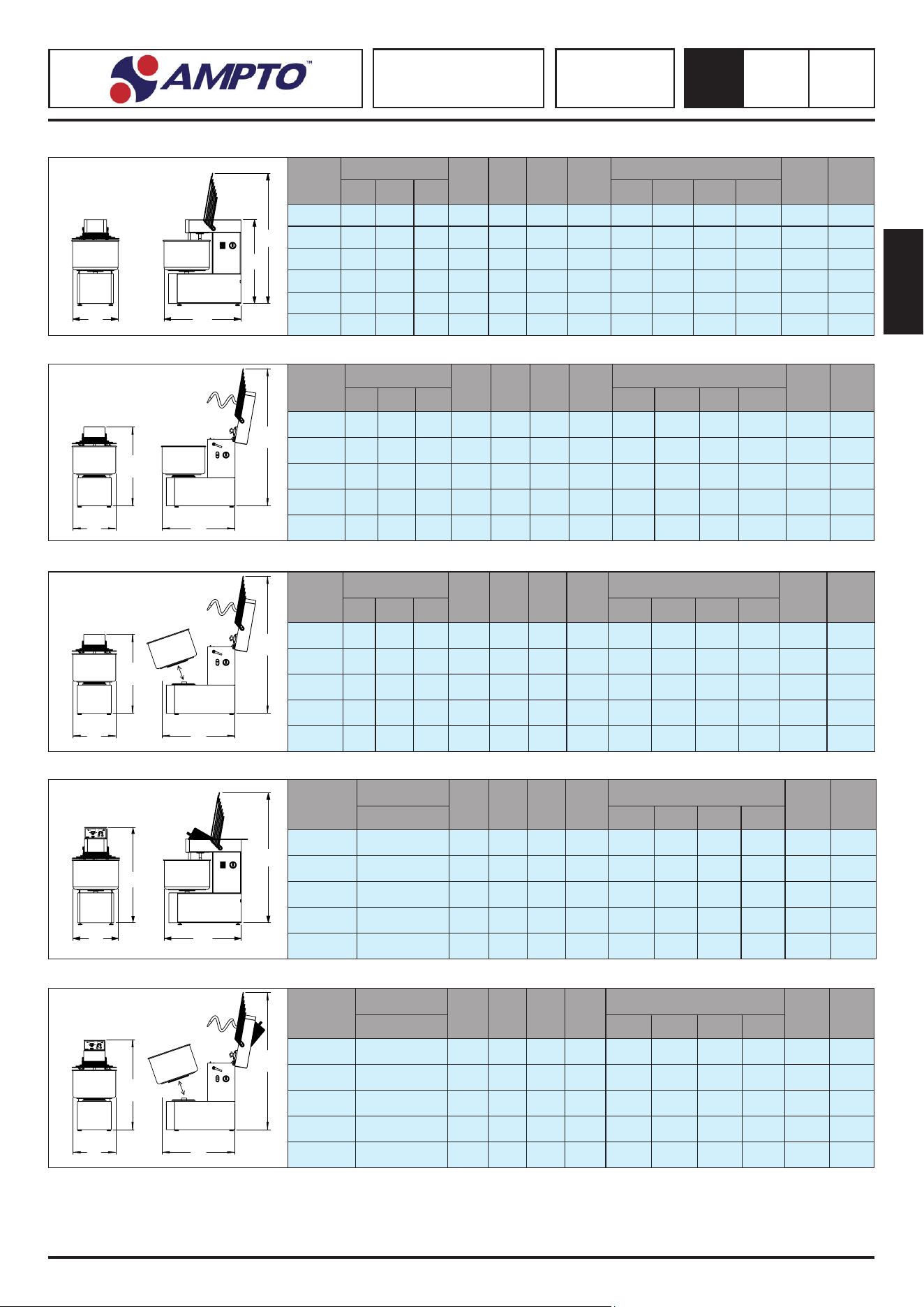
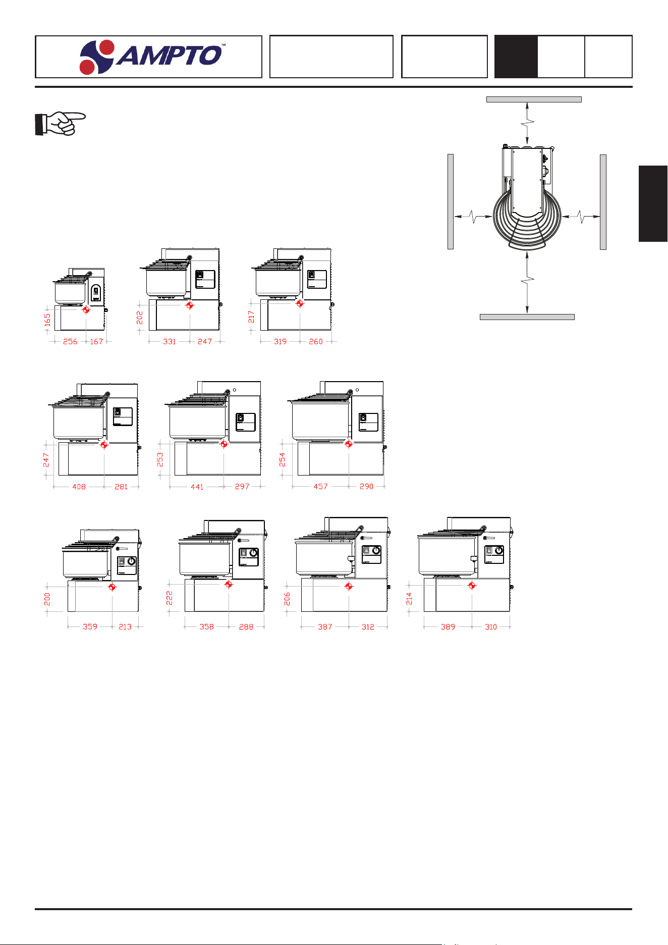
2.8. MACHINE DIMENSIONS MOD. SK
2.9. MACHINE DIMENSIONS MOD. RTF - SPIRAL MIXERS WITH RISING TOP
B
C
D
A
B
C
D
A
Model
Version
A B C D
Packaging Dimensions
Net
Weight
(Kg)
Gross
Weight
(Kg)
MO TR 2V
width depth height Mc
SK10 X - - 270 465 515 760 390 520 700 0.16 28.5 34.0
SK15 X X X 390 690 680 1010 450 770 840 0.28 56.5 66.5
SK20 X X X 390 690 680 1010 450 770 840 0.28 58.5 68.5
SK30 X X X 445 775 760 1090 510 790 930 0.38 83.5 95.0
SK40 X X X 485 830 780 1160 570 850 940 0.44 92.0 105.0
SK50 X X X 485 830 780 1160 570 850 940 0.44 96.0 109.0
2.10. MACHINE DIMENSIONS MOD. RTS - SPIRAL MIXERS WITH RISING TOP AND EXTRACTABLE BOWL
Model
Version
A B C D
Packaging Dimensions
Net
Weight
(Kg)
Gross
Weight
(Kg)
MO TR 2V
width depth height Mc
- - - - - - - - - - - - - -
RTF20 X X X 390 690 680 1060 450 770 840 0.28 71.0 81.0
RTF30 X X X 445 775 760 1070 510 790 930 0.38 99.0 110.0
RTF40 X X X 485 830 780 1190 570 850 940 0.44 114.0 126.0
RTF50 X X X 485 830 780 1190 570 850 940 0.44 116.0 128.0
B
C
D
A
Model
Version
A B C D
Packaging Dimensions
Net
Weight
(Kg)
Gross
Weight
(Kg)
MO TR 2V
width depth height Mc
- - - - - - - - - - - - - -
RTS20 X X X 390 690 680 1060 450 770 840 0.28 71.0 81.0
RTS30 X X X 445 775 760 1070 510 790 930 0.38 99.0 110.0
RTS40 X X X 485 830 780 1190 570 850 940 0.44 114.0 126.0
RTS50 X X X 485 830 780 1190 570 850 940 0.44 116.0 128.0
measures in mm
2.11. MACHINE DIMENSIONS MOD. SKV - SPIRAL MIXERS WITH VARIABLE SPEED
B
C
D
A
2.12. MACHINE DIMENSIONS MOD. RTSV - RISING HEAD SPIRAL MIXERS WITH VARIABLE SPEED
B
C
D
A
LEGEND
MO = MONOPHASE
TR = THREE-PHASE
2V = 2 SPEED
English
SPIRAL MIXER
SK - RTF - RTS
SKV - RTSV
3
0.0
40
INSTALLATION
3
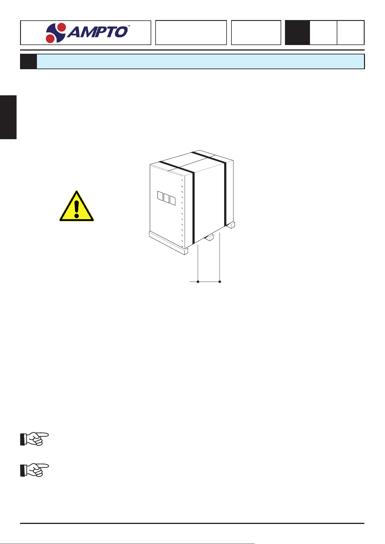
3.1. TRANSPORT AND HANDLING
The machine can be transported in a container or via couriers. The same type of packaging is required for both cases (see dimensions
and weight table).
The machine packaging must be protected against atmospheric agents. It is strictly prohibited to place other crates
or various materials on it. Handle the box with care. The box must be handled and transported by means of forklift
trucks or pallet trucks, making sure that the aachments of the liing means are posioned as shown in gure (FIG. 1)
Keep the load at the minimum height from the ground during handling operaons in order to improve the stability of the load.
Liing and handling operaons must be performed by specialist and authorised personnel.
The manufacturer declines any liability for damage to persons or objects resulng from failure to comply with the safety standards in
force relave to liing and moving materials inside and outside the plant.
3.2. STORAGE
The machine crate must be stored in an environment protected from atmospheric agents. It is strictly prohibited to place other
crates or various materials on it.
3.3. CHECKS UPON RECEIPT
Upon receiving the material, it is important to check:
1. crate number
2. weight and dimensions
3. correspondence between that indicated on the transport document and the material received
4. state and integrity of the packaging
5. that the packaging has not suered damage during transport.
If everything is intact, remove the packaging as specied in secon (see pos. 3.3/chap 3)
Any damage, faults, and non-conformies must be promptly communicated
within 8 days from the date of receiving the machine. Otherwise, the goods will be considered as accepted
On this point, the manufacturer reminds the user that, according to naonal and internaonal standards,
the goods travel at the buyer’s own risk.
Liing points
(FIG.1)
English
SPIRAL MIXER
SK - RTF - RTS
SKV - RTSV
3
0.0
41
1
1
2
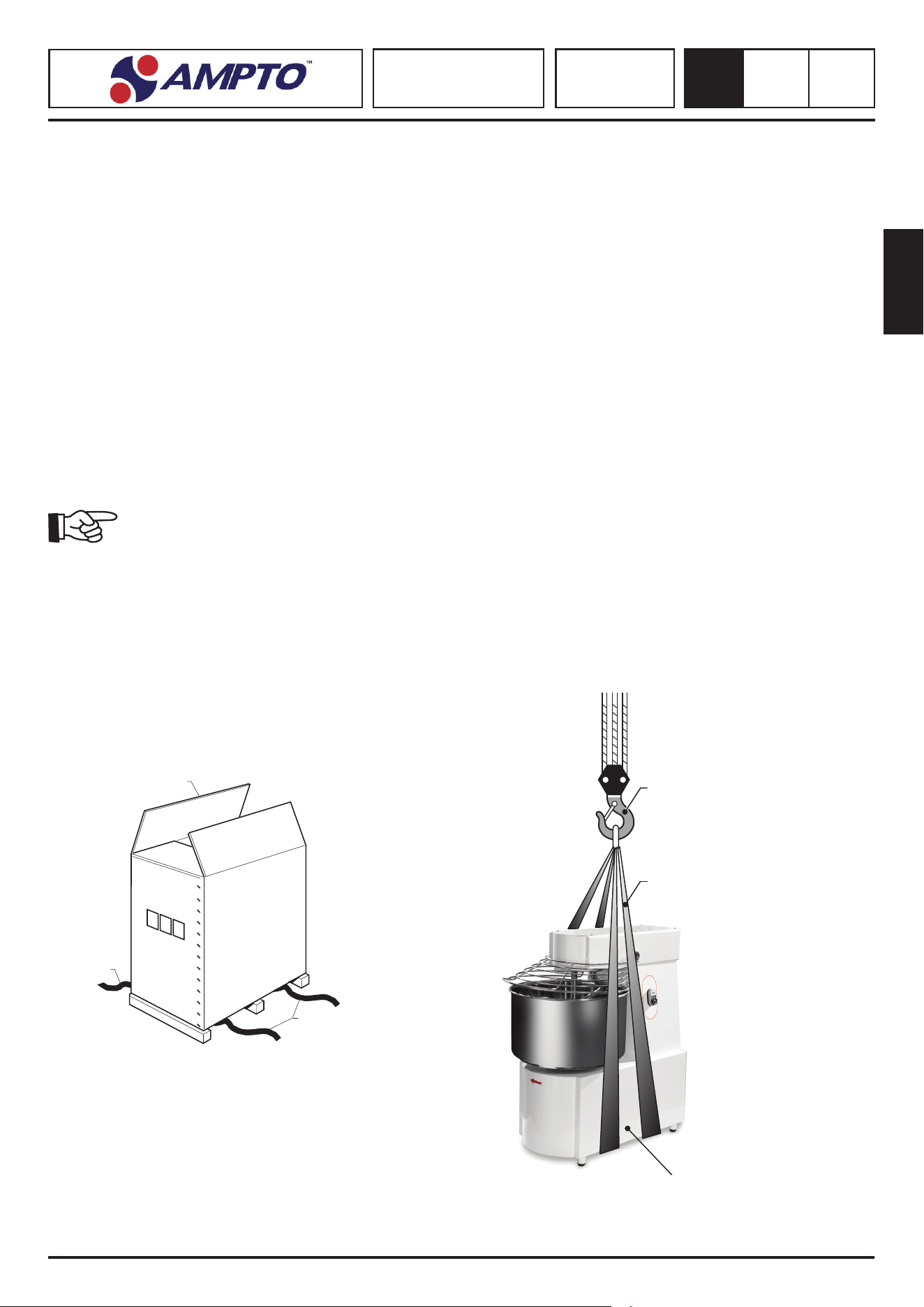
3.4. UNPACKING
Follow the instrucons below to remove the machine from the packaging:
see Fig. 2.
• Cut the straps (1) that block the cardboard
• Open the cardboard packaging (2) removing the staples
• Remove the cardboard casing (2)
• Make sure that everything is intact (see Pos. 3.3/Chap 3)
• Make sure that the supply complies with that indicated with the PACKING LIST.
3.5. LIFTING THE MACHINE (FIG. 3)
The machine (12 kg-18 kg versions) must be lied by two operators from the base. All the other models must be lied with a crane
or hoist, as follows:
• Insert two belts (1), suitably sized according to the machine weight, under the base (2) and connect them to the hook (3)
of a crane or hoist.
All the packaging components must be collected and sent to specic recycling centres
as described below.
(FIG. 2)
(FIG. 3)
3
1
2
English
SPIRAL MIXER
SK - RTF - RTS
SKV - RTSV
3
0.0
42
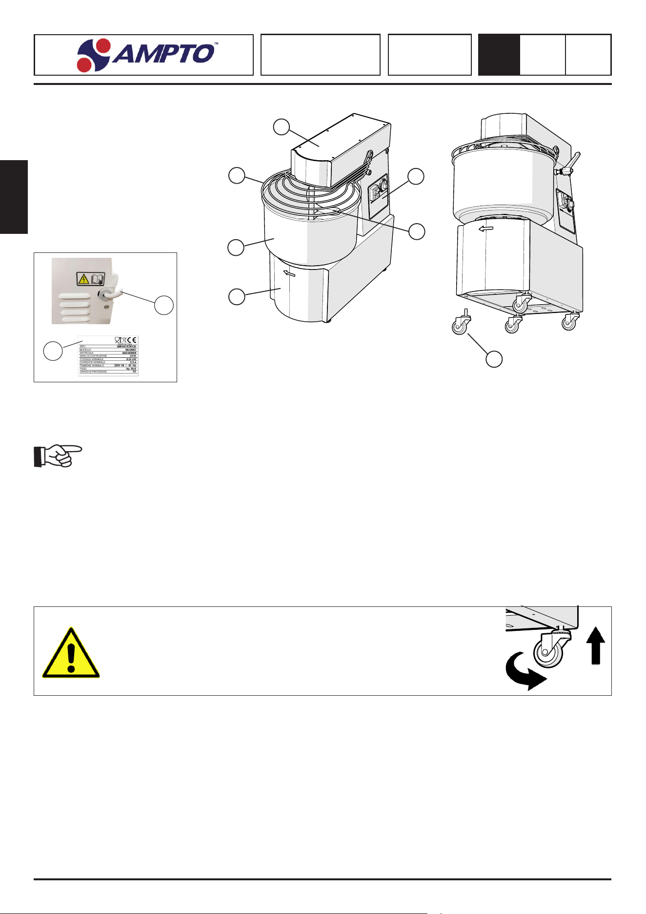
3.6. IDENTIFICATION OF THE COMPONENTS
1. Head
2. Control panel
3. Protecve grid
4. Tank
5. Base
6. Electric cable
7. Spiral
8. Adjustable wheels or feet
9. Data plate
3.7. IDENTIFICATION OF THE MACHINE (FIG. 4)
The serial number and machine idencaon data are stamped on the plate (9) on the machine base.
Always state the serial number and model of the machine to request Technical Assistance and order spare
parts.
3.8. ASSEMBLING THE WHEELS (FIG. 5)
Depending on the models and for transport reasons, the machines are always shipped with the adjustable feet/wheels removed.
Mount them as follows:
Assembling the wheels
1. Li the machine as indicated in the previous paragraph.
2. Loosen the exisng feet.
3. Tighten the wheels (8) under the machine base unl you reach the end of travel; the braking wheels must be ghtened on
the machine front.
! ! ! WARNING ! ! !
TO AVOID IRREPARABLE DAMAGE OR OVERFLOW OF THE MACHINE
COMPLETELY SCREW THE WHEELS UP TO THE END OF TRAVEL
( FIG. 5 )
8
1
2
5
3
7
4
(FIG. 4)
9
6
English
SPIRAL MIXER
SK - RTF - RTS
SKV - RTSV
3
0.0
43
400 mm
400 mm
1000 mm
400 mm
3.9. MACHINE POSITIONING AND STABILITY
Make sure that the support surface is suitable to support the loads indicated
in Tab. 2.7.
Posion the machine scrupulously respecng the indicaons given in Fig.
3.9.1. As they indicate the minimum distances necessary for the operator or technician
to correctly carry out each sequence of work and/or maintenance.
Taking into account the conformaon of the machine, in operang condions, it appears
to be stable without the need for xing to the oor, excluding the risk of overturning
or falling Fig.3.9.1.
Fig. 3.9.2. - Center of gravity of the machine
(FIG. 3.9.1)
SK10 SK15 SK20
SK30 SK40 SK50
RTF20/RTS20 RTF30/RTS30 RTF40/RTS40 RTF50/RTS50
English
SPIRAL MIXER
SK - RTF - RTS
SKV - RTSV
3
0.0
44
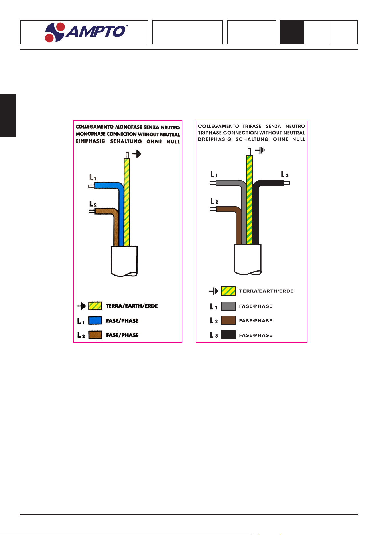
3.10. POWER SUPPLY
The electrical connecon must be made in compliance with the naonal standards
Der Anschluss an das Stromnetz der Maschine erfolgt dort über das mitgelieferte Netzkabel, an das bei einphasiger Ausführung 16/32
A für 3-polige Kabel (F, N, T) angeschlossen werden müssen und 4-polige Prüfungen (3F, T) für die dreiphasigen Versionen.
Die Netzsteckdose muss leicht zugänglich sein und darf keine Bewegung erfordern. Der Abstand zwischen Maschine und Steckdose
muss so sein, dass die Spannung des Stromversorgungskabels nicht beeinträchgt wird. Darüber hinaus darf sich das Kabel niemals
unter den Stützen der Maschine benden.
USER’S ELECTRICAL SYSTEM
The user’s system upstream the machine control equipment must be designed
and installed in compliance with the safety rules concerning “user’s low voltage systems” (IEC3644/HD384/CEI 64-8-latest edions).
In relaon to the energy distribuon system, which powers the machine control equipment, the machine must belong to one of the
normalised TT or TN systems, in compliance with IEC364_4_41/HD382_4_41/CEI 64.8 (4_41) (latest edions).
According to the above provisions/indicaons, the relave earthing system must fully comply with
the applicable requirements for the coordinaon with the associated acve devices, in compliance with IEC364-5-54/HD382-5-54/
CEI 64.8 (5-54) (latest edions).
PROTECTION DEVICE AGAINST OVERCURRENT
The equipment is designed to withstand a symmetrical short circuit of short duraon, which does not exceed 6kA. If the rated
condional prospecve short-circuit current in the installaon point is greater than the value indicated, it must be suitably limited.
Since the electrical equipment used to control the machine is not ed with d. c. electronic circuits, we recommend taking acon
to guarantee protecon against indirect contact. In order to protect against automac power supply interrupon be equipped with
SUITABLE DIFFERENTIAL DEVICES.
English
SPIRAL MIXER
SK - RTF - RTS
SKV - RTSV
3
0.0
45
REAR SIDE
The dierenal switch must withstand an impulse voltage of atmospheric origin and switching surges (cfr. EN 61008-1 latest edi-
ons).
Moreover,
1. the power supply disconnecng device on the top of the electrical panel has no rated
breaking capacity, as it is a socket/plug combinaon; moreover, it must be protected against
short circuit with a protecon device with rated current not higher than the technical data,
2. upstream of the electrical equipment power cable there must be the protecon device against over-current in
compliance with the technical rules
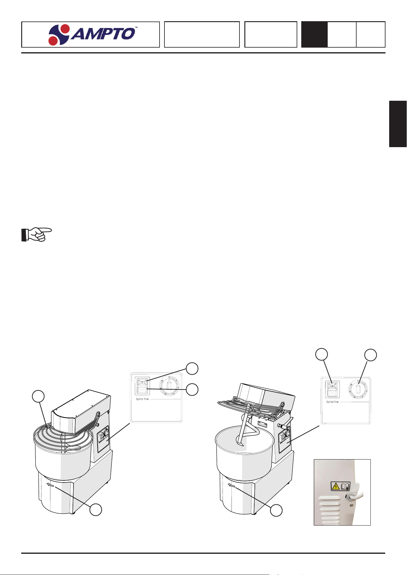
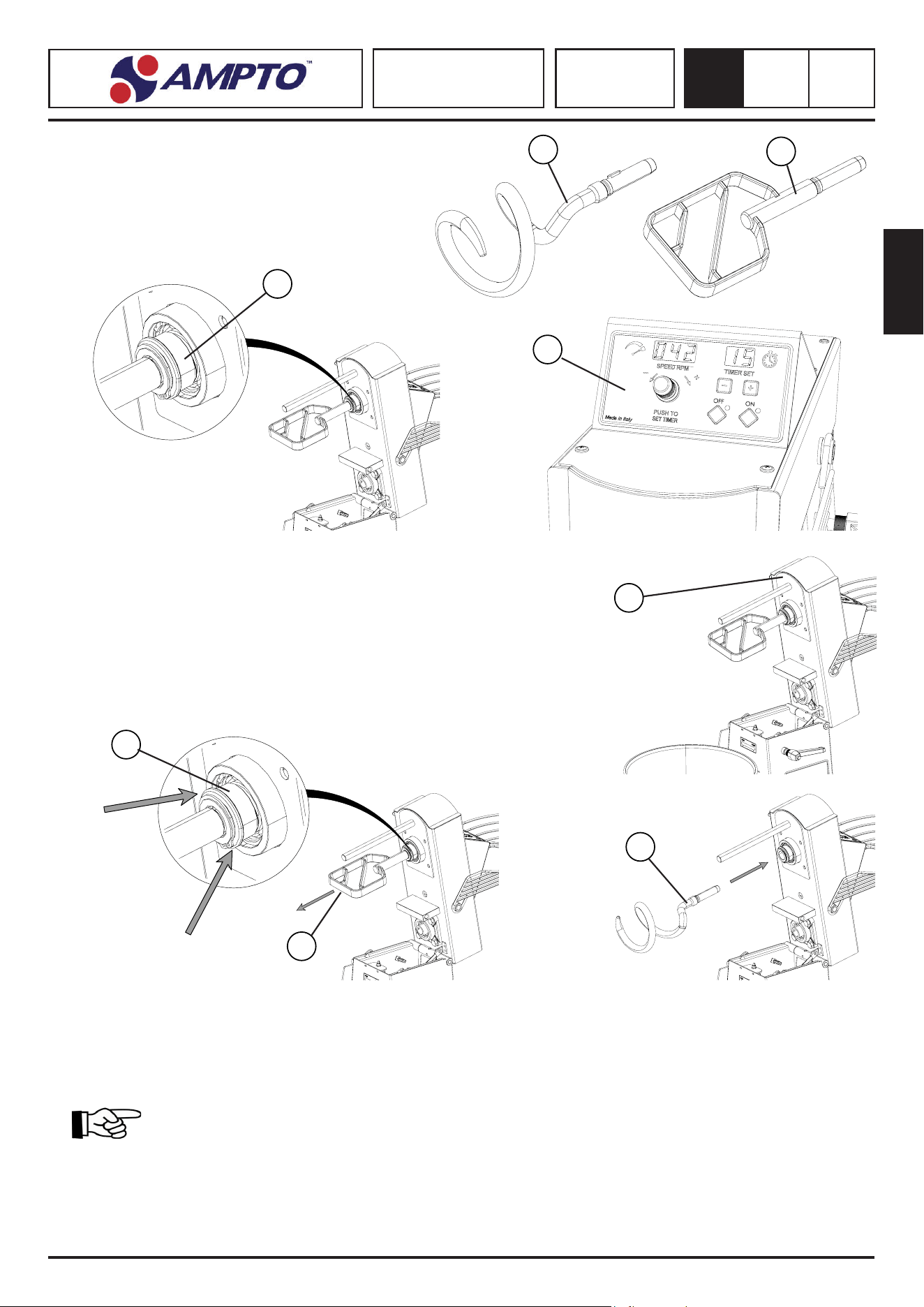
3.11. CHECKING THE ELECTRICAL CONNECTION (FIG. 7)
For the 230/400 V three-phase connecon, make sure that the motor rotaon is correct by following the procedure below:
• Set the main switch upstream the machine to ON.
• Turn the mer knob (2) to “30 Minutes” (for the models provided with mer)
• Press key (1) “ I ” .
• Visually check that the tank (3) rotates in the direcon indicated by the arrow (4).
• Switch the machine o by pressing key “ O ” (5) .
• If the rotaon is in the opposite direcon indicated by the arrow, act as follows:
Before modifying the electrical connecon, make sure that the LINE DISCONNECTING SWITCH is disabled
(line not live), therefore:
INVERT TWO OF THE THREE PHASE WIRES ON THE MAIN SWITCH AND CHECK FOR CORRECT ROTATION AGAIN.
3.12. FIRST START-UP (FIG. 8)
• Set the main switch upstream the machine to ON.
• Turn the mer knob (2) to “30 Minutes” (for the models provided with mer)
• Press key (1) “ I ”.
• Make the machine run with no load for a few minutes and make sure that rotaon is smooth.
• Switch the machine o by pressing key “ O ” (5).
SPIRAL MIXER FIXED HEAD SPIRAL MIXER HEAD TIPPING
(FIG. 7) (FIG. 8)
3
1
5
1
2
4
4
English
SPIRAL MIXER
SK - RTF - RTS
SKV - RTSV
4
0.0
46
SAFETY
4
4.1. SAFETY INSTRUCTIONS
Failure to apply safety rules and procedures can cause sources
of danger and damage.
The machine is understood to be bound in its use by the end
user.
1. All the rules of conduct of people established by the laws in force in your
country are applicable, with parcular reference to the electrical system
upstream of the machine for its connecon/operaon.
2. All further instrucons and warnings for use that are part of the graphic
documentaon admied to the machine.
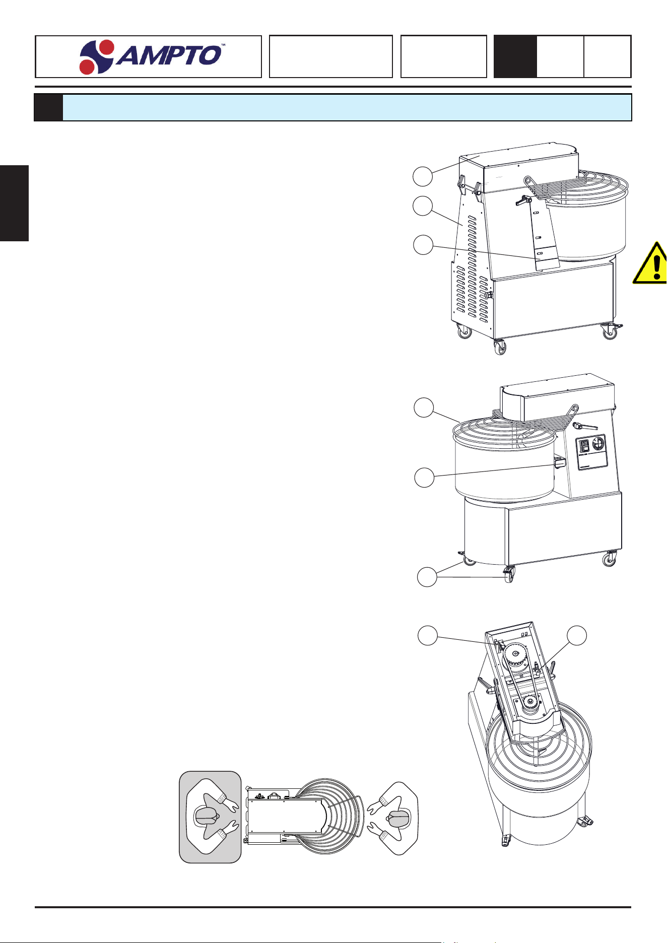
4.2. SAFETY DEVICES (FIG. 9)
The protecons and safety devices of the machine must not be removed. If they
are to be removed for extraordinary maintenance needs, measures must be taken
to minimize the resulng danger.
The machine is protected by a bodywork, which does not allow access to any
dangerous part, except in the front of the work, protected by an interlocking mobile
guard that covers the front of the moving tank.
The machine is equipped with the following safety systems:
(1) (2) All dangerous areas are closed by carters xed with screws.
(3) Protecve casing between the kneading body and the bowl the space
remaining between the crankcase and the bowl must be adjusted at a distance
equal to less than 5mm.
(4) The tank protecon grid prevents access to the tank when the mixer is running
(5) In the lng head mixer (40 and 50kg) there are idle rollers that help keep
the bowl of the mixer aligned during rotaon.
(6) If the mixer has wheels, it has front wheels with a brake. It is recommended
to always keep the machine braked.
(7) The xed head machine is equipped with a microswitch, which blocks the
operaon of the machine when the protecon grid (1) is raised;
(8) The lng head machine is equipped with a double microswitch, which blocks
the operaon of the machine when the protecon grid is raised and when
the head of the kneader is raised.
When the machine stops due to the inseron of one of the two safety microswitches,
it is necessary to press the “I” or “II” key again, depending on the model, to restart
the machine.
4.3. OPERATOR ZONES (FIG. 4.1)
During the operaon of the machine, the operator is posioned in front of it so that
the dough can be easily inserted and removed in the bowl; for the various allowed
posions see posion (O).
The technician is allowed to posion (T) on the rear of the machine for maintenance
operaons.
2
1
3
4
6
5
78
T
(FIG. 4.1)
O
English
SPIRAL MIXER
SK - RTF - RTS
SKV - RTSV
4
0.0
47
4.4. NORMAL USE, IMPROPER USE, PROHBITED USE
The machine described in this user manual is intended to be used BY ONE SINGLE trained OPERATOR, who is informed on the resid-
ual risks and safety rules, and by the maintenance technicians.
The machine is normally used to mix so dough made with our, salt, yeast, fats, liquids (water, eggs, ..) potatoes
and minced meat and other food ingredients.
The machine must not be used IMPROPERLY, in parcular:
1. It must not run with parameters other than those indicated in the TECHNICAL DATA table.
2. Any use of the machine running with parameters other than those indicated in this manual.
THE MANUFACTURER DECLINES ANY LIABILITY
1. The user is liable for damage resulng from failure to comply with this manual.
2. DO NOT RUN THE MACHINE WITH NO LOAD.
3. Do not tamper with, wear, remove, or hide the labels.
The machine must not be used IN A PROHIBITED WAY as it may cause damage or injuries to the operator.
1. It is prohibited to move the machine when connected to the power supply
2. It is prohibited to pull the power cable or the machine to disconnect the plug
3. It is prohibited to place weights on the machine while running.
4. It is prohibited to place the power cable on sharp parts.
5. It is prohibited to leave the machine unaended when it is loaded.
6. It is prohibited to place any object under the machine base or between the support feet and base
7. It is prohibited to introduce products or objects with features other than those indicated for normal use
8. It is prohibited to run the machine with protecve and xed guards fully removed.
9. It is prohibited to use products that may put the operator and maintenance technician’s health at risk;
moreover, they must not determine potenally explosive zones, as the machine is not designed to process
potenally explosive ingredients
10. It is prohibited to use direct water jets or other liquids.
THE USER IS LIABLE for damage resulng from failure to comply with the specied normal use condions. FOR
ANY DOUBTS, PLEASE CONTACT THE AUTHORISED ASSISTANCE CENTRE.
4.5. WARNINGS ON RESIDUAL RISKS
The employer must train the personnel on the risk of injury, safety devices, and general accident-prevenon rules
set-forth in the European standards and laws in force in the country of installaon of the machine.
Therefore, THE USER MUST:
1. Aend professional training courses, in collaboraon with the machine manufacturer, so that the OPERA
TORS AND MAINTENANCE TECHNICIANS are suitably trained.
2. Provide personal protecve equipment in compliance with Direcve 89/656/EEC and subsequent
amendments.
3. Use, cleaning, and maintenance operaons must be performed by QUALIFIED personnel
4.6. RESIDUAL RISKS
RESIDUAL RISK DUE TO NOISE
The machine produces an A-weighted sound power level lower than 70 dB.
Wear ear plugs or a headset to protect your ears.
English
SPIRAL MIXER
SK - RTF - RTS
SKV - RTSV
4
0.0
48
RESIDUAL RISK DUE TO FIRE
The employer must set up re-ghng systems (e.g. rst aid portable re exnguishers) suitable for the type of
materials that can catch re, near the machine work area. NEVER USE WATER TO FIGHT FIRE.
RESIDUAL RISKS DUE TO CONTROL SYSTEMS
• Upon acvaon of the machine or due to lack of power supply, BEFORE ACCESSING
THE MOBILE PARTS, MAKE SURE THAY HAVE ACTUALLY STOPPED.
• Entanglement aer opening the protecon grid for accidental actuaon of the start buon.
• Moving organs aer opening the protecon grid for accidental actuaon of the start buon
RESIDUAL RISK DUE TO THE OPENING OF THE PROTECTION GRID
• Entanglement aer opening the protecon grid for accidental actuaon of the start buon.
• Moving organs aer opening the protecon grid for accidental actuaon of the start buon
•
RESIDUAL RISK DUE TO REMOVAL OF FIXED PARST
The operator must never open or remove a xed guard or tamper with a safety device.
RISK DUE TO LIFTING OPERATIONS
There is the residual risk of impacng, abrasion, and crushing during maintenance, cleaning,
and other manual operaons.
RISK OF SLIPPING AND/OR FALLING
To prevent the risk of slipping and/or falling, the operator or maintenance technician must always use suitable feet-
protecon devices, such as an-slip shoes.
RISK DUE TO THE NATURE OF THE PRODUCT
The machine is designed to mix dough made with our, salts, yeast, fats, and liquids and other food ingredients.
In the presence of dust or powder, wear a suitable protecve mask during the manual work cycle and when the
machine is running. Addional ingredients must not be a risk for the operator’s healt. Moreover, no potenally
explosive atmospheres must be created.
RISK DUE TO THE NATURE OF THE PRODUCTS
The machine is designed to mix dough made with our, salts, yeast, fats, and liquids and other food
ingredients. In the presence of dust or powder, wear a suitable protecve mask during the manual
work cycle and when the machine is running. Addional ingredients must not be a risk for the
operator’s health. Moreover, no potenally explosive atmospheres must be created.
RISK DUE TO DUST
Airborne dust may form while loading dry products in the tank or during processing. Ingredients must be handled
with care, minimising the load height of the tank in which they are poured. The operator must use breathing
devices, such as dust-proof masks or other suitable devices.
English
SPIRAL MIXER
SK - RTF - RTS
SKV - RTSV
5
0.1
49
USE OF THE MACHINE
5
5.2. COMMISSIONING SPIRAL MIXER Mod. SK, RTF, RTS
Once the operator has checked that all safety condions are met, he can start the machine according to the procedure below:
Insert the food ingredients into the tank manually making sure the guard is OPEN. During machine operaon, the remaining ingredi-
ents can be inserted into the tank with the guard CLOSED.
Handle the food ingredients with care, reducing the minimum height from the tank edge.
The packaging on the lower part of the tank must be open to facilitate the removal of the our powder within
the shortest me possible
Li the protecve grid (1) and introduce the ingredients into tank (2) to obtain the dough. The machine capacity is suitable for standard
dough (about 65% of our and 35% of water). The capacity decreases for more compact dough.
Lower the protecve grid (1) and turn the main switch on to power the machine.
Start the machine according to the instrucons provided in the previous chapter (Chap 5.1)
Moreover
MANUAL MODE
• The processing lasts unl it is
stopped by the user.
• Set the “slow” speed or the
“fast” speed” to rotate.
• Press buon I - II (O) to start
the machine.
MODE WITH TIMER
• The processing lasts until the
TIMER is set
• Set the “slow” speed or the
“fast” speed” to rotate
• Press buon I - II (O) to start
the machine.
1
2
Dashboard with tmer
(optonal)
2 speeds Spiral Mixer
dashboard with tmer
(optonal)
b
a
c
d
d1
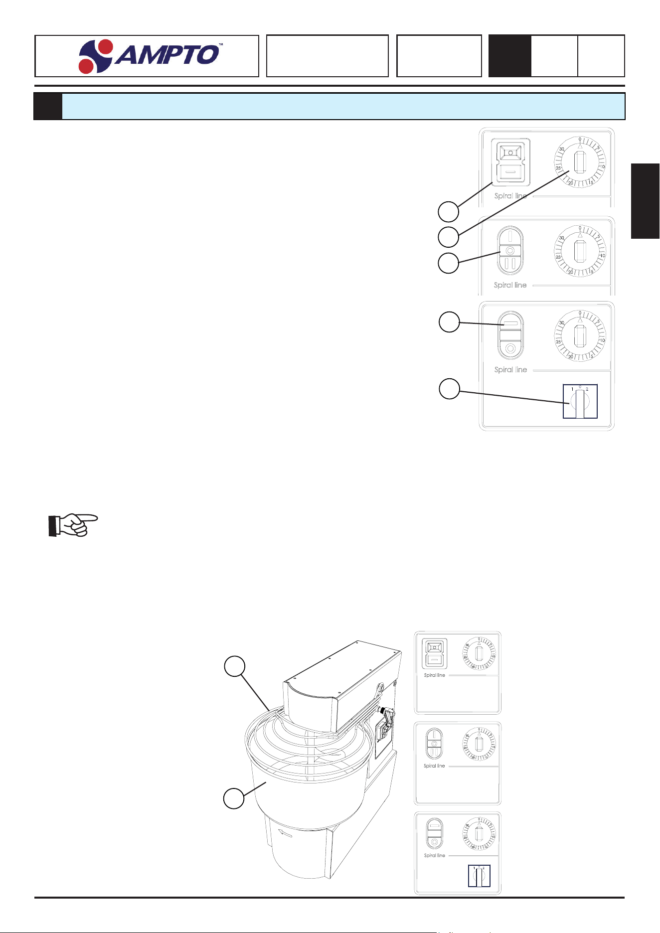
5.1. CONTROL PANEL
On the machine, depending on the models, the following commands are posioned:
a) START/STOP Buon.
Green Buon “I”, if pressed it starts the machine
Red buon “O”, if pressed it stops the machine
b) Timer (oponal) The mer is in posion “OFF” at 0/30 minutes
Turn the mer knob (1) clockwise to set the operang minutes (from 0 to 30
minutes); then, to start the cycle, press “I” or “II”, depending on the models; the
cycle ends when the mer knob (1) reaches posion “O” and the machine operaon
is disabled.
c) 2-SPEED START/STOP Buon (oponal)
Green Buon “I”, if pressed it starts the machine at speed 1
Green Buon “II”, if pressed it starts the machine at speed 2
Red buon “O”, if pressed it stops the machine
d) Speed selector (if present)
The selector has 3 posions:
d1 - 0. Opereon of the machine is disabled
d1 - 1. Machine works on standard velocity
d1 - 2. Machine works on second velocity
Once you set the speed, you must press the starter Green Buon “I” to start the
machine.
2 speeds Spiral Mixer
dashboard with selector
and mer (optonal)
English
SPIRAL MIXER
SK - RTF - RTS
SKV - RTSV
5
0.1
50
5.3. STOP
Press the red key “O” OFF to stop the machine
In the case of a temporary or prolonged stop, before restarng the machine, remove all the food ingredients inside the machine.
In the case of a prolonged stop, isolate the main system from the power supply, i.e. posion
the MAIN switch to “O” OFF
5.4. SWITCHING OFF
Follow the procedure below to switch the machine o:
1. Wait for the machine to complete the operaon, before switching it o
2. Stop the machine by acvang the control device“O” OFF
3. Remove the dough from the tank
4. Posion the MAIN switch to “O” OFF
5. Clean the machine
5.5. OPERATION SAFETY
In the event the machine is stressed or overloaded, it stops immediately as soon as the gear motor thermal protecon is triggered.
In this case, wait for the machine to cool down completely before restarng it.
5.6. NO VOLTAGE
In the case of a power failure, it can be restored by following the start-up procedure.
5.7. OPENING THE MOBILE GUARD
By liing the interlocked mobile guard, the machine stops immediately as soon as the safety micro switch is triggered.
The machine can be restarted only aer you have fully lowered the guard and followed the start-up procedure.
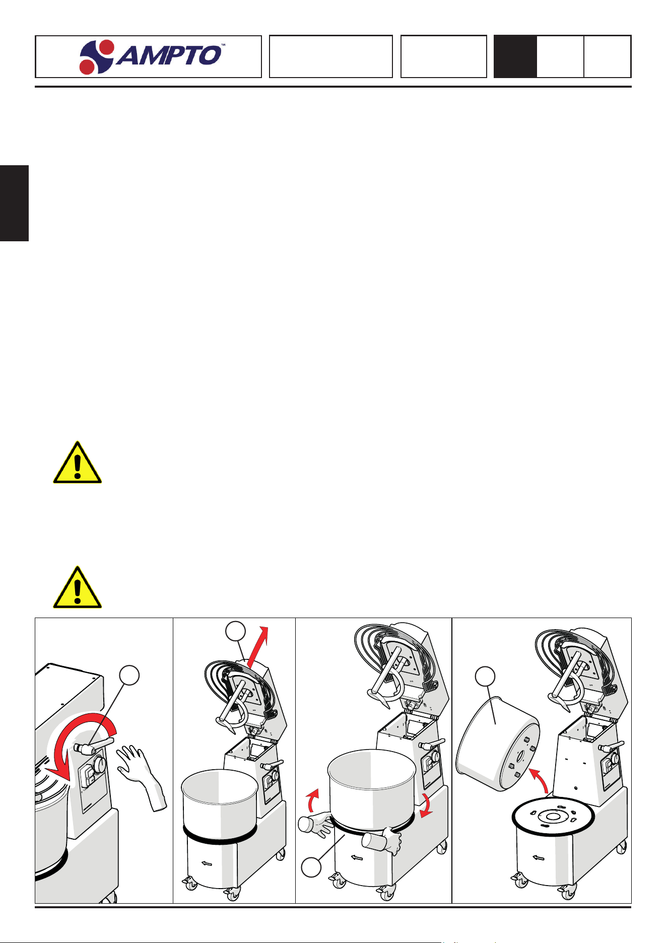
5.8. REMOVING THE TANK (where provided) (FIG. 15)
If the mass of the removable tank plus the content exceeds 25 kg, handling by a single operator is strictly prohibited.
In any case, it is recommended to remove the dough from the bowl and then proceed with the extracon for
cleaning.
• Stop the machine, disconnect the plug, unscrew the head-blocking handles (a) Fig.5.8.1 and li the head (b) Fig.5.8.2
• Grab with both hands the disc (c) placed under the bowl and turn it clock-wise Fig.5.8.3.
• Li the bowl (d) and extract it, one or two operators might be required, according to the weight Fig.5.8.4
• Place the bowl back in the working posion, using the dedicated housing and turn the disc (c) counterclockwise ll it blocks.
• Put the machine head down back in the working posion and screw the head-blocking handles (a).
It is strictly prohibited to run the machine with the tank posioned improperly
a
Fig. 5.8.1 Fig. 5.8.2 Fig. 5.8.3
Fig. 5.8.4
b
c
d
English
SPIRAL MIXER
SK - RTF - RTS
SKV - RTSV
5
0.1
51
5.9. COMPONENTS IDENTIFICATION Mod. SKV E RTSV
1. Spiral Tools (Mod. RTSV)
2. Beater Tools (Mod. RTSV)
3. Tool release ring (Mod. RTSV)
4. Control panel variable speed spiral mixer
3
2
1
4
5.10. REPLACEMENT OF MIXING TOOLS RTSV
a. Raise the mixer head as described in chapter 5
b. Push the tool release ring as indicated by the arrow
c. Remove the Beater
d. Insert the spiral forcefully by making the shot to the ring nut
e. Act in reverse order to reassemble the Beater
a
b
c
d
5.11. COMMISSIONING SPIRAL MIXER Mod. SKV, RTSV
Once the operator has checked that all safety condions are met, he can start the machine according to the procedure below:
Insert the food ingredients into the tank manually making sure the guard is OPEN. During machine operaon, the remaining ingredi-
ents can be inserted into the tank with the guard CLOSED.
Handle the food ingredients with care, reducing the minimum height from the tank edge.
The packaging on the lower part of the tank must be open to facilitate the removal of the our powder within
the shortest me possible
Li the protecve grid (1) and introduce the ingredients into tank (2) to obtain the dough. The machine capacity is suitable for standard
dough (about 65% of our and 35% of water). The capacity decreases for more compact dough.
Lower the protecve grid (1) and turn the main switch on to power the machine.
Start the machine according to the instrucons provided in the previous chapter (Chap 5)
English
SPIRAL MIXER
SK - RTF - RTS
SKV - RTSV
5
0.1
52
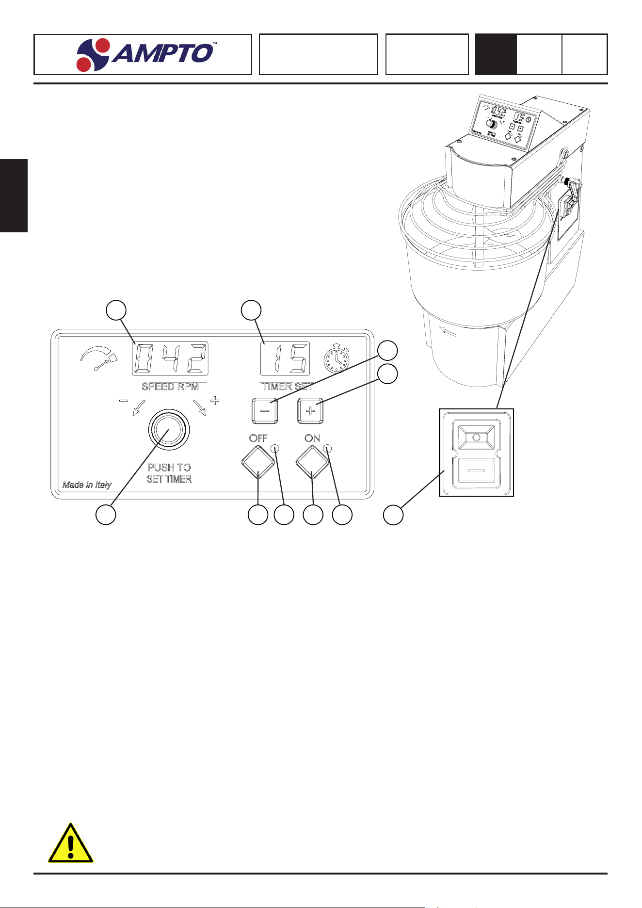
5.12. CONTROL PANELS SKV AND RTSV MIXER WITH VARIABLE SPEED
1. Display revoluons per minut Dough Mixer (RPM)
2. Display Timer (1-99 minutes)
3. Buon “-” me Timer
4. Buon “+” me Timer
5. Knob
• ROTATION = Speed adjustment
• PRESSION = mer acvaon
6. Buon “ OFF “
7. Light indicator
• PERMANENT = Standby
• FLASHING = Processing break
8. Buon “ON”
9. Machine operaon indicator light
• PERMANENT = Mixer in operaon
• FLASHING = Adjustment of set speed/raising grid
10. Switch
5.13. SET-UP MIXERS SKV, RTSV
MANUAL OPERATION:
1. Turn on the mixer with the switch (10) “I” buon
2. Aer the “BIP” wait 3 seconds unl the LEDs are stabilized
3. Press the ON buon (8) to start the mixer
4. Turn the knob (5) unl the desired speed is reached, the value will be shown on the display (1)
5. To stop the machine press the OFF buon (6) or li the kneader grid
6. To resume machining, press the ON buon (8)
7. At the end of processing, switch o the machine with the switch (10) “O” buon
1
2
5 6 7 8 9
3
4
10
TIMER OPERATION:
1. Turn on the mixer with the switch (10) “I” buon
2. Aer the “BIP” wait 3 seconds unl the LEDs are stabilized
3. Press the knob (5) to acvate the TIMER funcon the display will light up (2)
4. Use the “+” and “-” buons (3, 4) to adjust the TIMER me shown on the display (2)
5. Press the ON buon (8) to start the mixer
6. Turn the knob (5) unl the desired speed is reached, the value will be shown in the display (1)
7. To suspend processing, press the OFF buon (6) or li the kneader grid
8. To resume machining, press the ON (8) buon
9. To stop machining or to reset the TIMER me, press the OFF buon twice (6)
10. At the end of processing, switch o the machine with the switch (10) “O” buon
Engine-saving sofware: in case the operators sets a high speed for working a too hard dough, it reduces the
rounds of the spiral to avoid permanent damages.
English
SPIRAL MIXER
SK - RTF - RTS
SKV - RTSV
6
0.0
53
MAINTENANCE
6
6.1. REQUISITES OF THE MAINTENANCE TECHNICIAN
The term “maintenance” does not refer just to the periodical check of the machine’s normal operaon but also includes resolving all
those causes that put the machine out of service.
Personnel must read and understand this manual and be aware of the residual risks before carrying out maintenance operaons.
Maintenance operaons, replacements, gear adjustments, and trouble shoong must be carried out by qualied and authorised
personnel.
ALL MAINTENANCE, CLEANING, AND REPLACEMENT OPERATIONS MUST BE PERFORMED WITH THE MACHINE
AT STANDSTILL AND ISOLATED FROM EXTERNAL POWER SUPPLY SOURCES.
Pay aenon to the labels on the machine before carrying out maintenance, cleaning and replacement operaons.
IMPORTANT: During maintenance, cleaning, and replacement operaons, never tamper with or
remove the warning labels and the safety devices.
The maintenance technician is in charge of:
Adjusng the machine, calibrang the internal gears, even within the danger zones with closed and blocked xed guards, and dan-
gerous mobile components powered o and blocked.
Cleaning the internal parts of the machine, performing maintenance, providing technical assistance, troubleshoong, and replacing
worn parts.
6.2.MAINTENANCE PRESCRIPTION
REMOVAL OF GUARDS AND SAFETY DEVICES:
Some intervenons involve the removal of some guards from their posion.
ONLY A QUALIFIED MAINTENANCE TECHNICIAN CAN REMOVE THESE GUARDS.
Once maintenance operaons are complete, restore the inial posion of the guards and block them with the provided xing
systems.
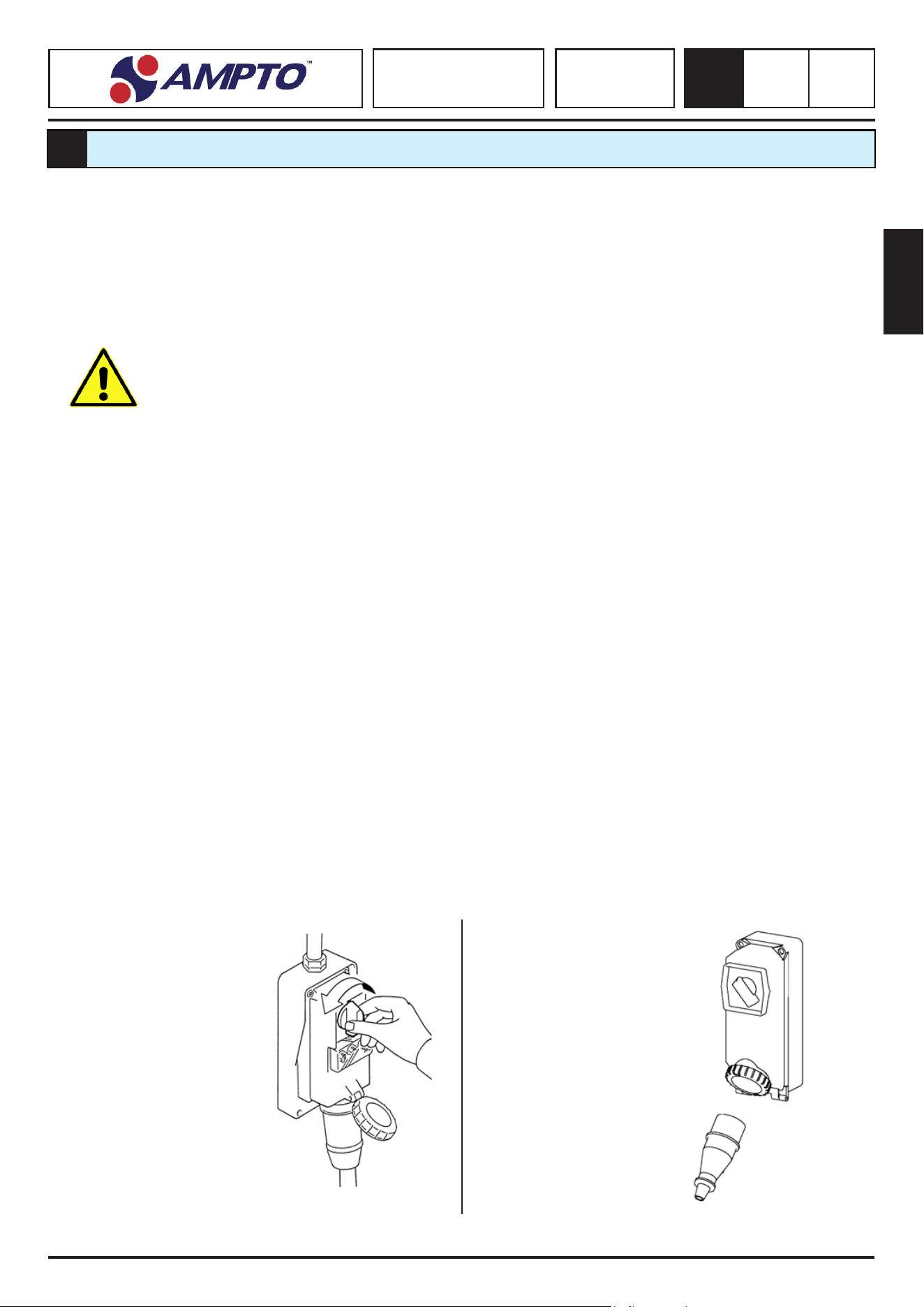
ISOLATION FROM EXTERNAL SOURCES:
The maintenance manager must isolate the machine from any external power supply source before removing the fixed
guards.
Posion the upstream
equipment electrical power
line protecon device on
“ZERO”.
Switch o the main breaker and
protect the plug by appropriate
means.
English
SPIRAL MIXER
SK - RTF - RTS
SKV - RTSV
6
0.0
54
Maintenance operaons are divided into two categories:
• ROUTINE MAINTENANCE:
Includes all the operaons that must be carried out on the
machine every day
• SCHEDULED MAINTENANCE:
Lists all the operaons that must be carried out
at xed intervals to guarantee the machine’s proper operaon.
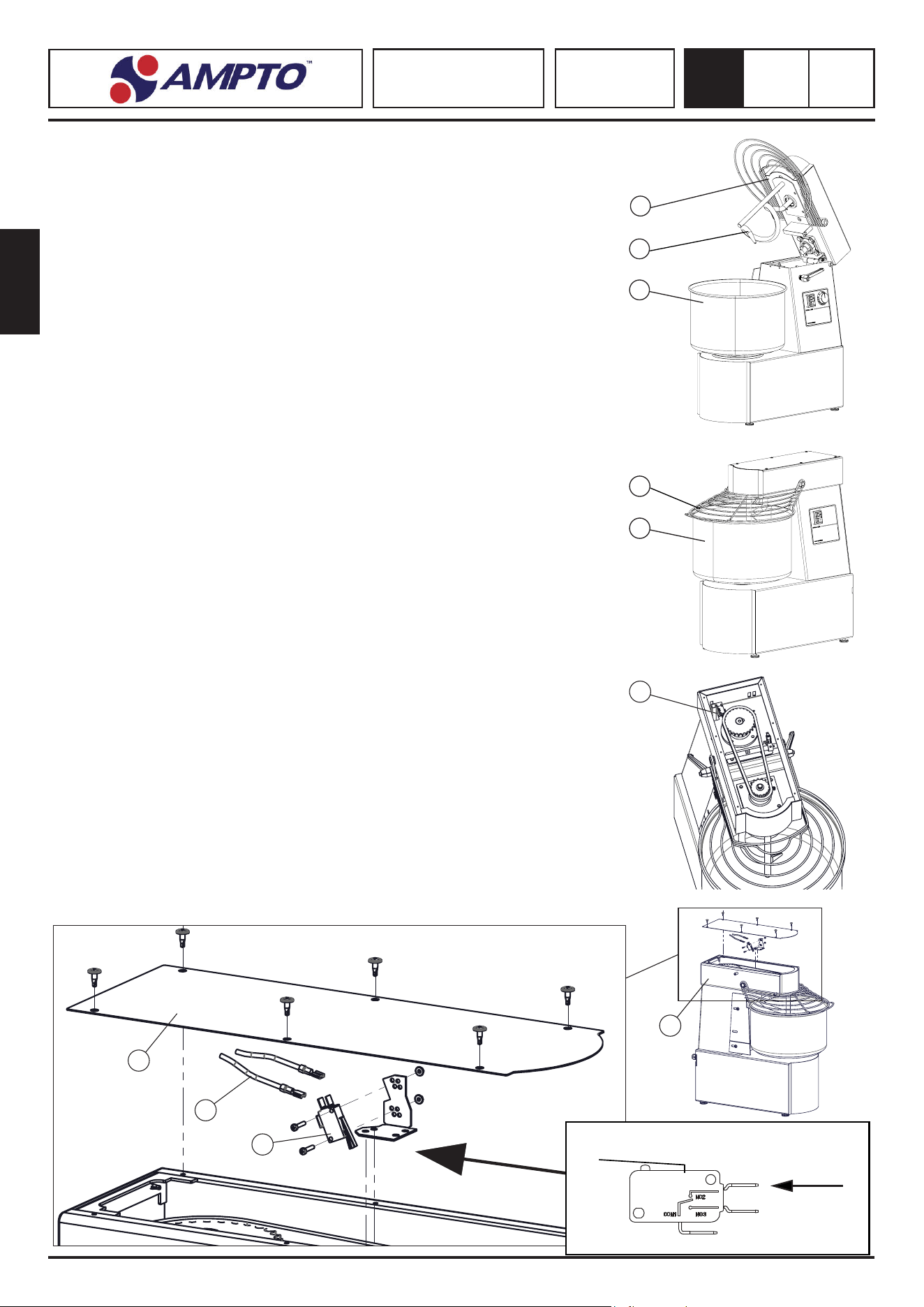
6.3. ROUTINE MAINTENANCE INTERVENTION
Cleaning the machine
• Clean the machine externally with a cloth dampened with water.
• Li the head (1) (if provided) and remove tank (2) as indicated in the relave
chapters.
• Clean the tank (2) with soap and with detergents or other degreasing but not
aggressive agents suitable for food-processing equipment.
• Clean the spiral (3) with a sponge dampened with water.
• Dry the various components and remount the tank and lower the head, if provided.
6.4. SCHEDULED MAINTENANCE INTERVENTION
Grid limit switch replacement
• Remove the upper casing (5) by unscrewing the screws
• Disconnect the microswitch cables (6)
• Replace the microswitch (7) with a new one with higher equivalent characteriscs
• Reconnect the cables in the contacts indicated by the arrows shown in (g. 6.4.1)
(ATTENTION the contacts must be connected in normally closed in the rest posion)
• Adjust the posion of the microswitch in such a way that it stops the operaon of
the machine as soon as the protecon grid is raised (4)
• Close the machine with the upper casing
Replacement of limit switch for kneading head raised
• Perform the same procedure as above with the microswitch that detects the raised
head (8)
3
1
2
3
2
5
7
Micro switch connecon ( FIG. 6.4.1 )
6
8
8
English
SPIRAL MIXER
SK - RTF - RTS
SKV - RTSV
6
0.0
55
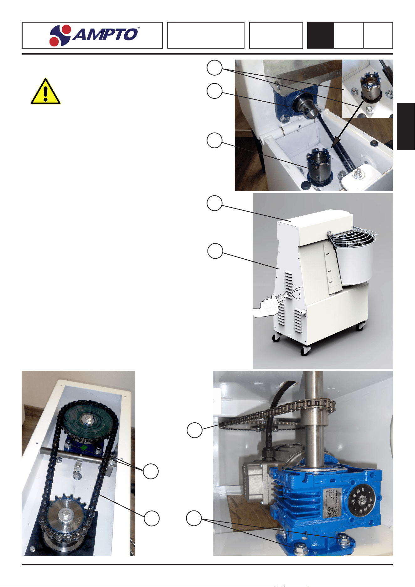
THIS OPERATION MUST BE CARRIED OUT BY A
QUALIFIED TECHNICIAN.
Chain tensioning
• Remove the rear casing (1) by loosening the relave screws.
• Loosen the nuts (2) of the gear motor and the screws
• Tension the chain (3) of the gear motor, stretch the chain. and
fully ghten the nuts (3).
• Grease the chain with grease suitable for gears.
Spiral rotaon chain tensioning.
• Remove the rear casing (1) by loosening the relave screws.
• Remove the head casing (4) by loosening the relave screws;
li the head, if provided.
• Loosen the nuts (5) of the bearing support and tension the
chain (6). Tighten the nuts (5).
• For the models equipped with folded head, centre the
transmission joint (7) with the relave hook joint (8) placed
on the machine structure.
• To perform adjustments, loosen nuts (9), check the coupling
of the joint and ghten nuts (9).
• Grease the chain and the bearing supports with grease suitable
for gears.
9
7
8
4
1
3
2
5
6

English
SPIRAL MIXER
SK - RTF - RTS
SKV - RTSV
6
0.0
56
6.5. CHECK LIST - ROUTINE MAINTENANCE
FREQUENCY VERIFICATION/CHECK METHODS AND FEEDBACK
Before each
working cycle
Check operaon:
• Safety devices
• Stop funcons
Make a visual inspecon and a funconal test of the control devices,of the
provided interlocks and the stop funcons in order to ensure their proper
operaon and the stopping of the moving parts.
! ! ! WA R N I N G ! ! !
In case of safety devices and shutdown funcons malfuncon,
immediately insulate the machine from the power supply and
call a qualied maintenance technician to check and analyse
the fault.
Before every work
shi
Check the work area:
• It must be clean and
free from dust
The workplace and all the external parts of the electrical equipment must
be clean; moreover it should be removed any part placed on the equipment
supplied that could prevent proper operaon and that could invalidate the
safety condions originally present in the electrical equipement.
At least once a
week
Visual integrity check:
• All idencaon plates
must be intact and not
worn
If it is unreadable, ask your service technician to replace idencal plaques.
At least once a
month
Visual integrity check:
• Tool and tank
The use of the parts indicated, determines their wear over me. Aer
cleaning, visually inspect the absence of chipping, cracking or breaking.
Where there are admissions of failure to proceed with their Replacement.
Any replacement must be made with the original products of the manufacturer.
6.6.CHECK LIST - SCHEDULED MAINTENANCE
FRQUENCY VERIFICATION/CHECK METHODS AND FEEDBACK
At least every
month
Check:
• inside the casing - motor
compartments
All the internal parts, motor compartments must be kept clean and
dry.
Sucon any dust or powder with a sucon device.
At least every
month
Check eecveness:
• Mechanical connecons
Use suitable tools to check the ghtness of the clamps, screws,
nuts, bolts, and connecons in general.
Adjust the tension of the motor transmission chains
At least every 3
months
Check funconality:
• motor drive contactors and all the
relays of the control circuit.
Visually inspect the state of the relays and control circuits.
At least every 6
months
Check eecveness:
• Equipotenal and protecon circuit
Use suitable instruments to measure the resistance of the
system to the earth, to allow the values to fall within the limits
of acceptability in compliance with the standards in force in the
country where the machine is installed.
At least every 3
months
General checks:
• Electrical appliances
Make the enre equipment electric for operaonal requirements
Electrical equipment is subject to wear
At least every 6
months
Check:
• the electric isolaon of the motors
Use suitable instruments to measure the motor isolaon resistance
to allow the values to fall within the limits of acceptability in
compliance with the standards in force in the country where the
machine is installed.
At least every 6
months
Check:
• the consumpon of the single
phases of the motor
Use suitable instruments to measure the consumpon on every
motor ulity power conductor.
Values that fail to fall within a 10% range indicate a motor failure.
At least every 12
months
Check eecveness:
• of the electric component
connecons outside the casings
Check for any loosening. If detected, restore the connecons,
making them durable and lasng.
English
SPIRAL MIXER
SK - RTF - RTS
SKV - RTSV
6
0.0
57
6.8.TROUBLESHOOTING
Before starng any intervenon
Ax a sign indicang that maintenance is in progress.
1. Before starng the machine, always make sure that no one is carrying out cleaning or maintenance opera
ons.
2. Ask qualied and enabled electricians to check and perform small electrical repair operaons.
3. Contact the authorised assistance service to repair mechanical parts.
Below is the list of intervenons useful to resolve faults and to release the mobile elements, which can be carried out by mainte-
nance technicians.
Type Potenal cause Mode
No mains voltage General black out Contact the electrical energy supplier.
Intervenon of fuses or circuit
breakers upstream of the power
supply to the machine
Restore the protecon device once you have solved the cause
that triggered it.
In the event the problem persists, contact an electrician.
"Operaon
interrupon"
Intervenon of the protecon
device inside the machine
Restore the protecon device once you have solved the cause
that triggered it.
In the event the problem persists, contact an electrician.
“The machine does not work
both the tank and tool fail to
rotate”
No voltage Check and restore the power supply.
Disconnecng devices “OFF” Turn the disconnecng devices to posion “ON”
Fuses triggered or Magneto-
thermal switches do not work
Replace the triggered fuses, check the state of the circuit
breakers.
Failure
start buon
Check the eciency of the START buon
Thermal trip Wait for the machine to cool down before restarng it
6.7. CHECK LIST - SCHEDULED COMPONENT REPLACEMENT
In any requests for technical assistance or in ordering spare parts, always quote the serial number of the machine plus the
model.
FREQUENCY COMPONENT TO REPLACE INTERESTED MACHINES
At least every 12
months
Wheel microswitch that controls the opening of the mixer Kneaders with liing head
At least every 5
years
Toggle microswitch that controls the opening of the metal grid that
protects the tank
All models of mixer
At least every 5
years
Replace the KM1 and KM2 contactors One speed, single-phase lng
kneaders

English
SPIRAL MIXER
SK - RTF - RTS
SKV - RTSV
6
0.0
58
6.9. CLEANING
BEFORE ANY CLEANING OPERATION, MAKE SURE THAT THE EQUIPMENT IS NOT CONNECTED TO THE POWER SUPPLY
It is prohibited to clean the machine with components in moon.
All cleaning operaons must be carried out only aer having removed the food product from the machine and having deacvated
the power supply line.
Do not use detergents or tools to clean the machine that may scratch or damage the surfaces. Do not use abrasive sponges or
aggressive/corrosive products. Avoid using foam products, i.e. self-cleaning products for ovens.
Do not clean the equipment with water or pressurised steam jets, as they may damage the electrical system. Use commercial and
approved products. Comply with the use methods and use suitable personal protecve equipment.
IMPORTANT
The machine must be cleaned upon every work shi. All the surfaces and machine parts intended to come into contact with the
food product, i.e. food areas (internal surface of the tank and of the mobile guard, tool, kneader rod, and front part of the machine)
and external surface of the machine must be cleaned and disinfected.
CLEANING DIAGRAM
• Clean the surfaces from any residue of food product with plasc scrapers;
• Sucon the residue of our or food products with a sucon device;
• Clean the food surfaces and spray areas with a so and damp cloth;
• Clean inside the tools with a sponge. Use liquid products specic for steel. Do not use abrasive, cream or paste products or
products containing chlorine. Use denatured alcohol to clean greasy substances.
IMPORTANT
Once the stainless steel products, especially the external surfaces of the appliance, are fully dry, they must be protected with prod-
ucts commonly available on the market (i.e. Vaseline oil), which eliminate various halos, restoring the shine to steel and prevenng
humidity and dirt, which are causes of corrosion, from penetrang.
USEFUL TIPS WHEN PERFORMING MAINTENANCE ON STAINLESS STEEL COMPONENTS
Stainless steel is resistant to corrosion because it has a thin oxide protecve lmwhich forms on the surface at a molecular level and it
is caused by oxygen being absorbed by the metal aer exposure to air.
It is clear that any external cause (such as foreign material placed on it, residue of food or salts, etc.), which prevents this lm from
forming and its prolonged presence on the surface, reduces its resistance against corrosion.
English
SPIRAL MIXER
SK - RTF - RTS
SKV - RTSV
7
0.0
59
SCRAPPING, DEMOLITION AND DISPOSAL
7
7.1. SCRAPPING
Scrapping is the end of the equipment’s life cycle. It becomes necessary when overall the elements that compose it do not ensure
safe and ecient operang condions. Most of the components are recyclable.
7.2. DEMOLITION
The principal sequenal steps for the disassembly and demolion include:
• Disconnect the cables from all components inside the electrical panel and all the components installed on the machine and send
them to waste collecon instuons or companies in compliance with applicable law;
• Remove all components from inside the electrical panel and installed on the machine and send them to waste collecon instu-
ons or companies in compliance with applicable law;
• All the metal or plasc bodywork, the screws and any other parts in steel of plasc must be sent to waste collecon instuons
or companies in compliance with applicable law;
7.3. DISPOSAL
The electrical equipment can not be disposed as urban waste, the separate collecon introduced by the special rules for the disposal
of waste material derived from electric equipment (ld No. 151 of 07/25/05 - 2002/96/EC - 2003/108 /EC) must be complied with.
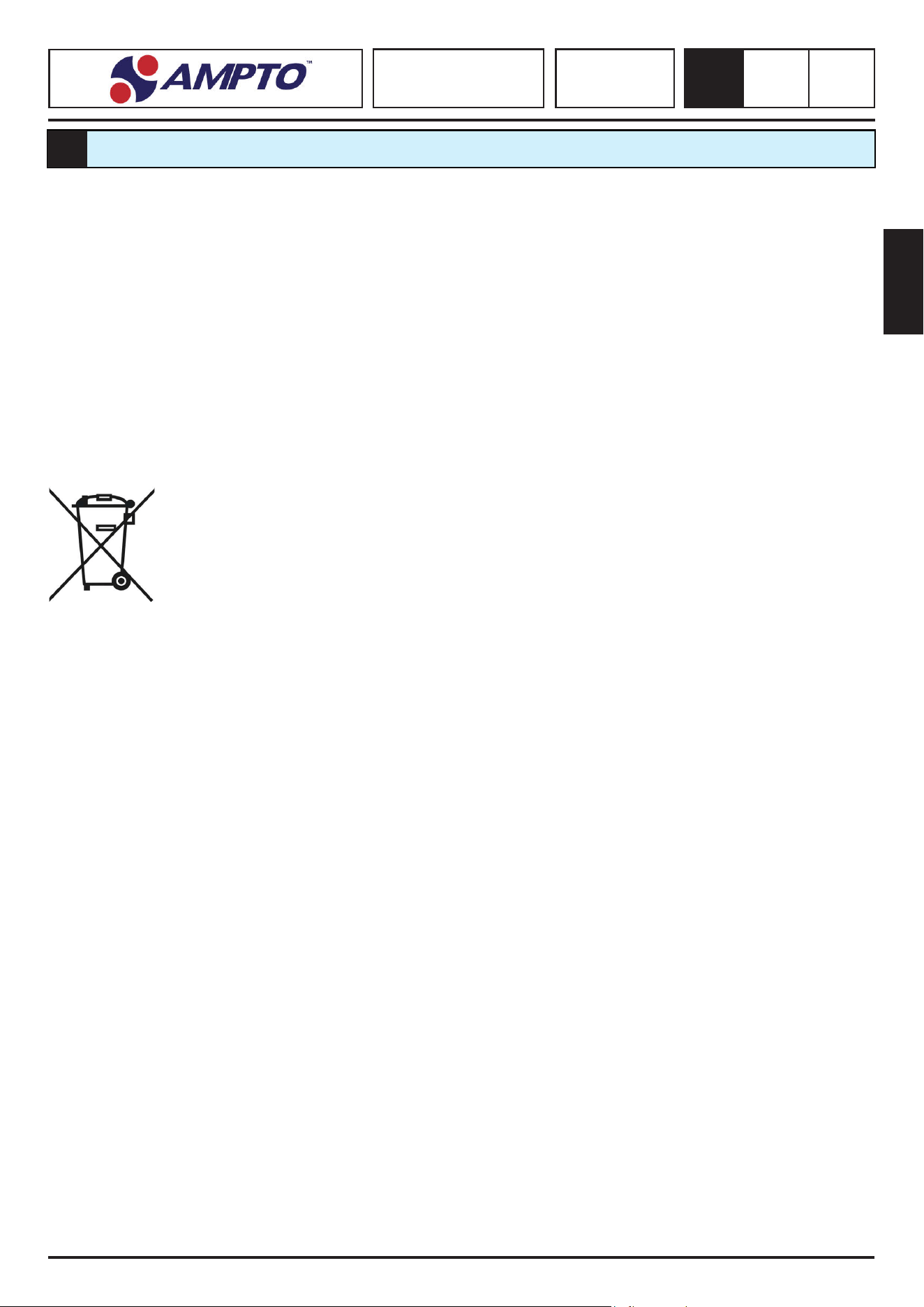
Electrical equipment is marked with a symbol showing a barred trash container on wheels. The symbol indicates that the equipment
has been placed on the market aer August 13, 2005 and that it should be subject to separate waste collecon. The inadequate or
illegal disposal of the equipment can cause harm to people and the environment, due to the substances and materials contained
therein. The disposal of electrical waste that does not meet the applicable standards implies the applicaon of administrave and
penal sancons.
IMPASTATRICE A SPIRALE
SPIRAL MIXER
TEIGKNETMASCHINEN
ÉLECTRIQUE PÉTRINS À SPIRAL
AMASADORAS CON ESPIRAL
SK - RTF - RTS
SKV - RTSV
8
0.0
144
SCHEMI ELETTRICI
ELECTRIC SCHEMES / SCHALTPLÄNE / SCHÉMAS ÉLECTRIQUES / DIAGRAMAS DE CABLEADO
8
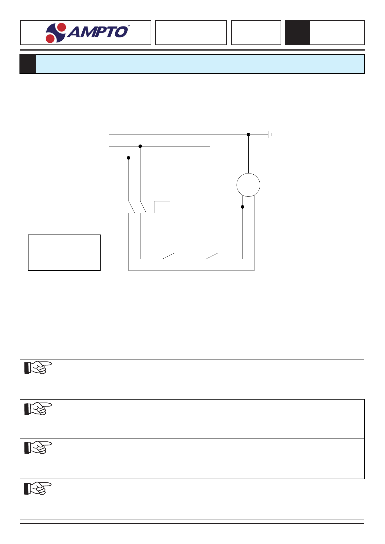
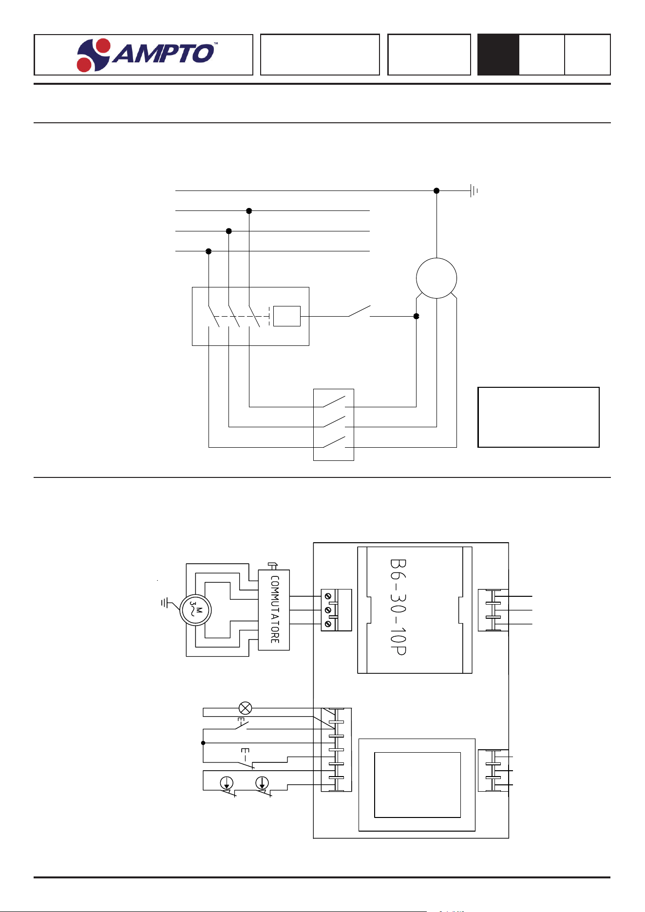
8.1. SK & RTF 230/1 V - 50 Hz - 1-Velocità / 1-Speed / 1-Geschwindigkeit / 1-Vitesse / Velocidad
SK10 - SK15 - SK20 - SK30 - SK40 - SK50
RTF20 - RTF30 - RTF40 - RTF50
IT:
Le apparecchiature ed i loro relavi conta sono rappresenta in posizione “OFF” di non funzionamento del quadro
EN:
The devices and their contacts are represented in the “OFF” posion of the non funconing electrical panel
DE:
Die produkte und ihre jeweiligen kontakte werden in “OFF” stellung des nichtbetriebs des arbeitsrahmen repräsenert
FR:
Les disposifs et leurs contacts respecfs sont représentés en posion “OFF” de non-fonconnement du cadre
ES: Los equipos y sus contactos se representan en posición “o” de no funcionamiento del tablero
IT:
ATTENZIONE: se la tensione di alimentazione varia piu del 10% bisogna installare un stabilizzatore di corrente
EN:
WARNING: if the supply voltage varies by more than 10% a current regulator must be installed
DE:
ACHTUNG: wenn die Versorgungsspannung mehr als 10% ändert, müssen Sie einen Überspannungsschutz installieren
FR:
ATTENTION: si la tension d’alimentaon varie de plus du 10%, vous devez installer un limiteur de surtension
ES:
!! ATENCIÓN !! Si la tensión de alimentación varía más del 10%, es necesario instalar un estabilizador de corriente.
IT:
E’ OBBLIGATORIO Dopo ogni trasporto e prima di ogni collaudo il serraggio di tue le vi
EN:
IT IS MANDATORY aer each transportaon and before each tesng to ghten all the screws
DE:
ES IST VORGESCHRIEBEN: nach jedem Transport und vor jeder Prüfung die Dichtheit der Schrauben zu testen
FR:
IL EST OBLIGATOIRE après chaque transport et avant chaque test l’étanchéité de toutes les vis
ES:
Es obligatorio después de cada transporte y antes de cada ensayo, ajustar todos los tornillos.
IT: L’alimentazione del quadro deve essere garanta da una adeguata protezione a monte
EN: Power to the electrical panel must be guaranteed by an adequate upstream protecon
DE: Die Kra der Rahmen durch einen hinreichenden Schutz muss aufwärts sichergestellt werden
FR: L’alimentaon du cadre doit être assurée par une protecon adéquate en amont
ES:
La alimentación del tablero debe estar garantzada por una protección antepuesta adecuada
PE
N
L
M
U<
GS
T
LEGEND:
M = MOTOR
T = TIMER
GS = GRID SENSOR
IMPASTATRICE A SPIRALE
SPIRAL MIXER
TEIGKNETMASCHINEN
ÉLECTRIQUE PÉTRINS À SPIRAL
AMASADORAS CON ESPIRAL
SK - RTF - RTS
SKV - RTSV
8
0.0
145
L1
TF1
U
W
LAMP.
START
STOP
MC1
MC1
L
STOPSTART
V
L2
TLR1
MOTORE
2 VELOC.
L3
COM
230
400
MC2
1-Velocità / 1-Speed / 1-Geschwindigkeit / 1-Vitesse / Velocidad
SK15 - SK20 - SK30 - SK40 - SK50
RTF20 - RTF30 - RTF40 - RTF50
2-Velocità / 2-Speed / 2-Geschwindigkeit / 2-Vitesse / Velocidad
SK20 - SK30 - SK40 - SK50
RTF20 - RTF30 - RTF40 - RTF50
8.2. SK & RTF 400/3 V - 50 Hz
PE
L3
L2
M
U<
L1
T
GS
LEGEND:
M = MOTOR
T = TIMER
GS = GRID SENSOR

IMPASTATRICE A SPIRALE
SPIRAL MIXER
TEIGKNETMASCHINEN
ÉLECTRIQUE PÉTRINS À SPIRAL
AMASADORAS CON ESPIRAL
SK - RTF - RTS
SKV - RTSV
8
0.0
146
RTS20 - RTS30 - RTS40 - RTS50
8.3. RTS 230/1 V - 1-Velocità / 1-Speed / 1-Geschwindigkeit / 1-Vitesse / Velocidad
IT:
Le apparecchiature ed i loro relavi conta sono rappresenta in posizione “OFF” di non funzionamento del quadro
EN:
The devices and their contacts are represented in the “OFF” posion of the non funconing electrical panel
DE:
Die produkte und ihre jeweiligen kontakte werden in “OFF” stellung des nichtbetriebs des arbeitsrahmen repräsenert
FR:
Les disposifs et leurs contacts respecfs sont représentés en posion “OFF” de non-fonconnement du cadre
ES: Los equipos y sus contactos se representan en posición “o” de no funcionamiento del tablero
IT:
ATTENZIONE: se la tensione di alimentazione varia piu del 10% bisogna installare un stabilizzatore di corrente
EN:
WARNING: if the supply voltage varies by more than 10% a current regulator must be installed
DE:
ACHTUNG: wenn die Versorgungsspannung mehr als 10% ändert, müssen Sie einen Überspannungsschutz installieren
FR:
ATTENTION: si la tension d’alimentaon varie de plus du 10%, vous devez installer un limiteur de surtension
ES:
!! ATENCIÓN !! Si la tensión de alimentación varía más del 10%, es necesario instalar un estabilizador de corriente.
IT:
E’ OBBLIGATORIO Dopo ogni trasporto e prima di ogni collaudo il serraggio di tue le vi
EN:
IT IS MANDATORY aer each transportaon and before each tesng to ghten all the screws
DE:
ES IST VORGESCHRIEBEN: nach jedem Transport und vor jeder Prüfung die Dichtheit der Schrauben zu testen
FR:
IL EST OBLIGATOIRE après chaque transport et avant chaque test l’étanchéité de toutes les vis
ES:
Es obligatorio después de cada transporte y antes de cada ensayo, ajustar todos los tornillos.
IT: L’alimentazione del quadro deve essere garanta da una adeguata protezione a monte
EN: Power to the electrical panel must be guaranteed by an adequate upstream protecon
DE: Die Kra der Rahmen durch einen hinreichenden Schutz muss aufwärts sichergestellt werden
FR: L’alimentaon du cadre doit être assurée par une protecon adéquate en amont
ES:
La alimentación del tablero debe estar garantzada por una protección antepuesta adecuada
RTS20 - RTS30 - RTS40 - RTS50
8.4. RTS 400/3 V - 50 Hz - 1 Velocità / 1-Speed / 1-Geschwindigkeit / 1-Vitesse / Velocidad
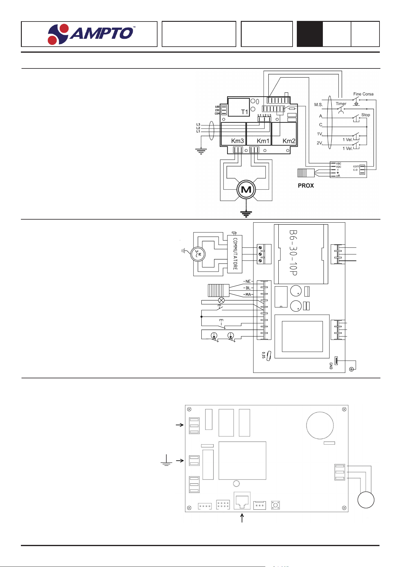
IMPASTATRICE A SPIRALE
SPIRAL MIXER
TEIGKNETMASCHINEN
ÉLECTRIQUE PÉTRINS À SPIRAL
AMASADORAS CON ESPIRAL
SK - RTF - RTS
SKV - RTSV
8
0.0
147
RTS20 - RTS30 - RTS40 - RTS50
8.5. RTS - 400/3 V - 50 Hz - 2-Velocità / 2-Speed / 2-Geschwindigkeit / 2-Vitesse / Velocidad
SKV10 - SKV15 - SKV20
SKV30 - SKV40 - SKV50
RTSV20 - RTSV30 - RTSV40 - RTSV50
8.6. SKV-RTSV - 230/1 V - 50 Hz MONOFASE - Velocità variabile / Variable speed / Unterschiedliche Geschwindigkeit
Vitesse variable / Velocidad variable
230 V
QUADRO COMANDI
CONTROL PANEL / SCHALTTAFEL / PANNEAU DE CONTRÔLE / PANEL DE CONTROL
M
TF1
LAMP.
START
STOP
MC1
RG1
C1
BR1
C2
C3
PROX
OUT
- +
MC1
L
STOPSTART
CV1
TLR1
MOTORE
2 VELOC.
U
W
V
L1
L2
L3
COM
230
400
MC1 MC2
RTS20 - RTS30 - RTS40 - RTS50
Con Commutatore / Switches / Schalter
Commutateurs / Interruptores


IMPASTATRICE A SPIRALE
SPIRAL MIXER
TEIGKNETMASCHINEN
ÉLECTRIQUE PÉTRINS À SPIRAL
AMASADORAS CON ESPIRAL
MOD. SK - RTF - RTS - SKV - RTSV
MF11000010 - 02/2020
AMPTO, INC
8409 NW 68th Street, Miami, FL 33166
Tel: +1 (877)-992-6211 ext. 303
Fax: +1 (305) 960-7796
www.ampto.com

