p/n: 614-09404
Revision 01
SMART1500RXLTAA
SMART2200RXLTAA
SMART3000RXLTAA
BP48VRXLTAA
BP72VRXLTAA
Advanced User Guide
Eaton Tripp Lite Series SmartPro TAA

©Copyright 2022 Eaton, Raleigh, NC, USA. All rights reserved. No part of this document may be reproduced in any way without the
express written approval of Eaton.
SSaaffeettyy IInnssttrruuccttiioonnss
SAVE THESE INSTRUCTIONS. This manual contains important instructions that should be
followed during installation and maintenance of the UPS and batteries.
This equipment has been tested and found to comply with the limits for a Class A digital device,
pursuant to Part 15 of the FCC Rules. These limits are designed to provide reasonable protection
against harmful interference when the equipment is operated in a commercial environment. This
equipment generates, uses, and can radiate radio frequency energy and, if not installed and used in
accordance with the instruction manual, may cause harmful interference to radio communications.
Operation of this equipment in a residential area is likely to cause harmful interference in which case
the user will be required to correct the interference at his own expense.
This is a category C2 UPS product. In a residential environment, this product may cause radio
interference, in which case the user may be required to take additional measures.
Suppliers Declaration of Conformity
Responsible Party:
EATON
10000 Woodward Ave
Woodridge, IL 60517 USA
773–869–1111
tripplite.eaton.com
FCC Compliance Statement:
This device complies with Part 15 of the FCC Rules. Operation is subject to the following two
conditions:
1. This device may not cause harmful interference, and
2. this device must accept any interference received, including interference that may cause
undesired operation.

SSppeecciiaall SSyymmbboollss
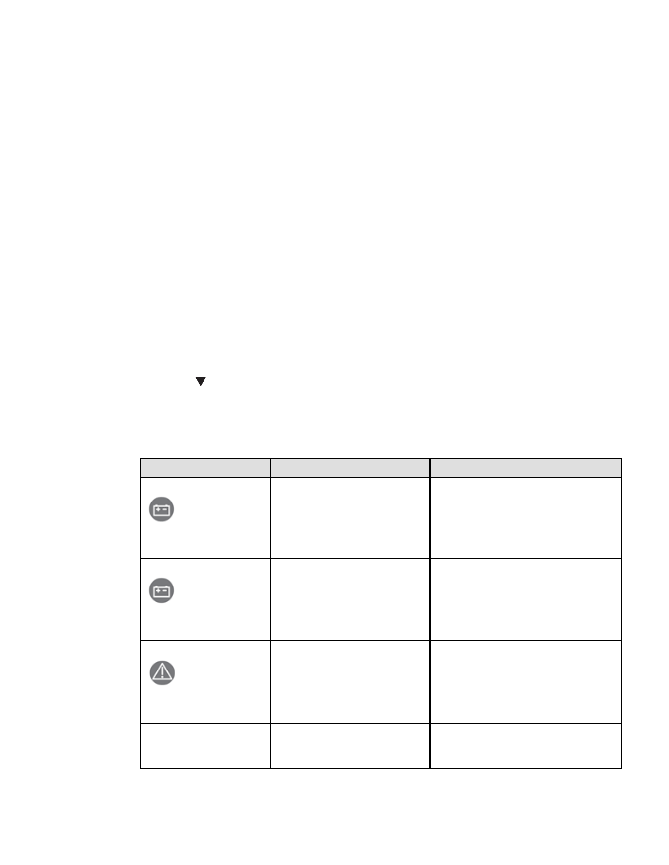
The following are examples of symbols used on the product to alert you to important information:
RISK OF ELECTRIC SHOCK - Observe the warning associated with the risk of
electric shock symbol.
CAUTION: REFER TO OPERATOR'S MANUAL - Refer to your operator's
manual for additional information, such as important operating and maintenance
instructions.
Information, advice, help.
Read the documentation provided.
Disconnect input plug.
Before maintenance, first shut down the UPS then disconnect the AC power
source, internal and external batteries then discharge capacitors by pressing the
ON button and wait 5 minutes.
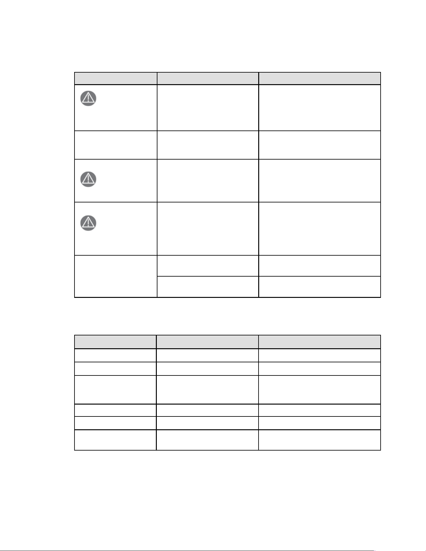
This equipment should only be used in a dry indoor environment.
Operating range of temperature.
Operating range of humidity.
The UPS and their batteries must be kept in a ventilated place.
SSaaffeettyy ooff PPeerrssoonnss
• The system has its own power source (the battery). Consequently, the power outlets may be
energized ven if the systems is disconnected from the AC power source. Dangerous voltage
levels are resent within the system. It should be opened exclusively by qualified service
personnel.
• The system must be properly grounded at all times.
• The battery supplied with the system contains small amounts of toxic materials. To avoid
accidents, the directives listed below must be observed:
– Servicing of batteries should be performed or supervised by personnel knowledgeable about
batteries and the required precautions.
– When replacing batteries, replace with the same type and number of batteries or battery
packs.
– Do not dispose of batteries in a fire. The batteries may explode.

– Batteries constitute a danger (electrical shock, burns). The short-circuit current may be very
high.
– UPS employing batteries with min. V-2 case are intended for use in computer room as
defined in the standard for the Protection of Information Technology Equipment, ANSI/NFPA
75.
– UPS employing batteries with HB case are intended not for use in a computer room as
defined in the standard for the Protection of Information Technology Equipment, ANSI/NFPA
75.
• Precautions must be taken for all handling:
– Wear rubber gloves and boots.
– Do not lay tools or metal parts on top of batteries.
– Disconnect charging source prior to connecting or disconnecting battery terminals.
– Determine if battery is inadvertently grounded. If inadvertently grounded, remove source
from ground. Contact with any part of a grounded battery can result in electrical shock. The
likelihood of such shock can be reduced if such grounds are removed during installation and
maintenance (applicable to equipment and remote battery supplies not having a grounded
supply circuit).
PPrroodduucctt SSaaffeettyy
• To connect the UPS, instructions and operation described in the manual must be followed in the
indicated order.
• CAUTION - To reduce the risk of fire, the unit connects only to a circuit provided with 20 or 30
amperes maximum branch circuit overcurrent protection in accordance with the National Electric
Code, ANSI/NFPA 70 (US installations only).
• Check that the indications on the rating plate correspond to your AC powered system and to the
actual electrical consumption of all the equipment to be connected to the system.
• For PLUGGABLE EQUIPMENT, the socket-outlet shall be installed near the equipment and shall
be easily accessible
• Never install the system near liquids or in an excessively damp environment.
• Never let a foreign body penetrate inside the system.
• Never block the ventilation grates of the system.
• Never expose the system to direct sunlight or source of heat.
• If the system must be stored prior to installation, storage must be in a dry place.
• The admissible storage temperature range is -25ºC to +55ºC without batteries, 0°C to 40°C with
batteries.
• This UPS can be used in IT/TT/TN power system. This UPS complies with the IP20 protection
type. Protective class I.
• Output short-circuit current max RMS & delay time: 90A/80ms; The max peak value: 140A.
• For 3K LV models, the upstream circuit breaker of UPS for installation must committee the
disconnection time in 0.4s according to requirement of IEC 60364-4-41:2005 Table 41.1.
• The system is not for use in a computer room AS DEFINED IN the standard for the Protection of
Information Technology Equipment, ANSI/NFPA 75 (US installations only).
• Changes or modifications not expressly approved by the party responsible for compliance could
void the user’s authority to operate the equipment.
SSppeecciiaall PPrreeccaauuttiioonnss
• The unit is heavy: wear safety shoes and use vacuum lifter preferentially for handling operations.

• All handling operations will require at least two people (unpacking, lifting, installation in rack
system).
• Before and after the installation, if the UPS remains de-energized for a long period, the UPS must
be energized for a period of 24 hours, at least once every 6 months (for a normal storage
temperature less than 25°C). This charges the battery, thus avoiding possible irreversible
damage.
• During the replacement of the Battery Module, it is imperative to use the same type and number
of element as the original Battery Module provided with the UPS to maintain an identical level of
performance and safety. If there are any questions, don’t hesitate to contact your local Eaton
representative. For potential safety issue on defective UPS : DISCONNECT INTERNAL BATTERY
for storage and transportation.
• All repairs and service should be performed by AUTHORIZED SERVICE PERSONNEL ONLY.
There are NO USER SERVICEABLE PARTS inside the UPS.


Eaton Tripp Lite Series SmartPro TAA User Guide 614-09404—Rev 01 vii
TTaabbllee ooff CCoonntteennttss
11 IInnttrroodduuccttiioonn....................................................................................................................................................................................................................................................................................................11
1.1 Introduction...............................................................................................................................................1
1.2 Environmental protection ............................................................................................................................. 1
1.3 Benefits.................................................................................................................................................... 2
1.4 Special Precautions.....................................................................................................................................2
22 PPrreesseennttaattiioonn ..................................................................................................................................................................................................................................................................................................33
2.1 Standard installation ....................................................................................................................................3
2.2 Optional accessories ................................................................................................................................... 3
2.3 Rear Panels ...............................................................................................................................................4
33 IInnssttaallllaattiioonn ......................................................................................................................................................................................................................................................................................................77
3.1 Inspecting the equipment.............................................................................................................................7
3.2 Recommended Positions ............................................................................................................................. 8
3.3 Connecting the Internal Battery ................................................................................................................... 10
3.4 EBM Connection ...................................................................................................................................... 11
3.5 UPS Connection ....................................................................................................................................... 13
44 IInntteerrffaacceess aanndd CCoommmmuunniiccaattiioonn .......................................................................................................................................................................................................................................... 1155
4.1 Control panel ........................................................................................................................................... 15
4.2 LCD Description ...................................................................................................................................... 16
4.3 Display Functions ..................................................................................................................................... 18
4.4 User Settings........................................................................................................................................... 19
4.5 Communication Ports ................................................................................................................................ 21
4.6 UPS Remote Control Functions ................................................................................................................... 22
4.7 Power Alert Software ................................................................................................................................ 26
4.8 Cybersecurity .......................................................................................................................................... 26
55 OOppeerraattiioonn........................................................................................................................................................................................................................................................................................................ 2277
5.1 Start-up and normal operation ..................................................................................................................... 27
5.2 Starting the UPS on battery......................................................................................................................... 27
5.3 UPS shutdown ........................................................................................................................................ 27
5.4 Operating modes...................................................................................................................................... 28
5.5 Return of AC input power .......................................................................................................................... 28
5.6 Configuring Battery Settings ...................................................................................................................... 28
5.7 Retrieving the event and fault log ................................................................................................................ 29
66 UUPPSS MMaaiinntteennaannccee................................................................................................................................................................................................................................................................................ 3311
6.1 Equipment Care ....................................................................................................................................... 31
6.2 Storing the Equipment ............................................................................................................................... 31
6.3 When to Replace Batteries ........................................................................................................................ 31
6.4 Replacing Batteries ................................................................................................................................... 31

viii Eaton Tripp Lite Series SmartPro TAA User Guide 614-09404—Rev 01
6.5 Recycling the Used Equipment.................................................................................................................... 33
77 TTrroouubblleesshhoooottiinngg .................................................................................................................................................................................................................................................................................... 3355
7.1 Troubleshooting ...................................................................................................................................... 35
7.1.1 Typical Alarms and Faults ..................................................................................................................... 35
7.1.2 Alarm or Fault Codes ........................................................................................................................... 36
7.1.3 Silencing the Alarm ............................................................................................................................ 37
7.1.3.1 Service and Support .................................................................................................................... 38
88 SSppeecciiffiiccaattiioonnss.......................................................................................................................................................................................................................................................................................... 3399
8.1 UPS Model List ........................................................................................................................................ 39
8.2 Extended Battery Module Model List ........................................................................................................... 39
8.3 Weights and Dimensions ........................................................................................................................... 39
8.4 Electrical Input ........................................................................................................................................ 40
8.5 Electrical Input Connections ....................................................................................................................... 40
8.6 Electrical Output ...................................................................................................................................... 40
8.7 Electrical Output Connection....................................................................................................................... 41
8.8 Battery .................................................................................................................................................. 41
8.9 Environmental and Safety........................................................................................................................... 42
Table of Contents

Eaton Tripp Lite Series SmartPro TAA User Guide 614-09404—Rev 01 1
CChhaapptteerr 11 IInnttrroodduuccttiioonn
11..11 IInnttrroodduuccttiioonn
Thank you for selecting an Eaton® Tripp Lite Series SmartPro TAA product to protect your electrical equipment.
The Eaton® Tripp Lite Series SmartPro TAA range has been designed with the utmost care. We recommend
that you take the time to read this advanced user guide to take full advantage of the many features of your UPS
(Uninterruptible Power System).
Before installing your Eaton® Tripp Lite Series SmartPro TAA, please read the information and safety
instructions provided.
Follow the instructions in the quick start guide and if necessary, refer to this advance user guide.
To discover the entire range of Eaton Tripp Lite Series products, we invite you to visit our web site at
tripplite.eaton.com or contact your Eaton Tripp Lite Series local representative.
11..22 EEnnvviirroonnmmeennttaall pprrootteeccttiioonn
Eaton® Tripp Lite Series has implemented an environmental-protection policy. Products are developed
according to an eco-design approach.
SSuubbssttaanncceess
This product does not contain CFC and HCFC. This product does not contain asbestos. This product is
compliant with regulations on the restriction of the use of substances in electrical and electronic equipment.
PPaacckkaaggiinngg
To improve waste treatment and facilitate recycling, separate the various packing components.
• The cardboard we use comprises over 50% of recycled cardboard.
• Plastic bags are made of polyethylene.
• Packing materials are recyclable and bear the appropriate identification symbol.
Table 1.
Materials Abbreviations Number in the symbols
Polyethylene terephthalate PET 01
High-density polyethylene HDPE 02
Polyvinyl chloride
PVC
03
Low-density polyethylene LDPE 04
Polypropylene PP
05
Polystyrene
PS
06
Follow all local regulations for the disposal of packing materials.
EEnndd ooff lliiffee
Eaton will process products at the end of their service life in compliance with local regulations. Eaton® Tripp
Lite Series SmartPro TAA works with companies in charge of collecting and eliminating our products at the end
of their service life.

2 Eaton Tripp Lite Series SmartPro TAA User Guide 614-09404—Rev 01
PPrroodduucctt
The product is made up of recyclable materials. Dismantling and destruction must take place in compliance
with all local regulations concerning waste. At the end of its service life, the product must be transported to a
processing center for electrical and electronic waste. tripplite.eaton.com/support/recycling-program
BBaatttteerryy
The product contains lead-acid batteries that must be processed according to applicable local regulations
concerning batteries. The battery may be removed to comply with regulations and in view of correct disposal.
11..33 BBeenneeffiittss
The Eaton Tripp Lite Series SmartPro TAA uninterruptible power system (UPS) protects your sensitive
electronic equipment from the most common power problems, including power outages, voltage sags,
impulsive transients, line noise, and long-term under and over voltage conditions, frequency variations,
switching transients, and harmonic distortion.
Power outages can occur when you least expect it and power quality can be erratic. These power problems
have the potential to corrupt critical data, destroy unsaved work sessions, and damage hardware - causing
hours of lost productivity and expensive repairs.
With the Eaton Tripp Lite Series SmartPro TAA, you can safely eliminate the effects of power disturbances and
guard the integrity of your equipment. Providing outstanding performance and reliability, the Eaton Tripp Lite
Series SmartPro TAA’s unique benefits include:
• Standard communication options: one RS-232 communication port, one USB communication port, relay
output contacts.
• Optional connectivity cards with enhanced communication capabilities.
• Extended runtime with up to four Extended Battery Modules (EBMs) per UPS.
• Remote on/off (ROO) and remote power off (RPO).
• Backed by worldwide agency approvals.
11..44 SSppeecciiaall PPrreeccaauuttiioonnss
• The unit is heavy: wear safety shoes and use vacuum lifter preferentially for handling operations.
• All handling operations will require at least two people (unpacking, lifting, installation in rack system).
• Before and after the installation, if the UPS remains de-energized for a long period, the UPS must be
energized for a period of 24 hours, at least once every 6 months (for a normal storage temperature less
than 25°C). This charges the battery, thus avoiding possible irreversible damage.
• During the replacement of the Battery Module, it is imperative to use the same type and number of
element as the original Battery Module provided with the UPS to maintain an identical level of performance
and safety. If there are any questions, donʼt hesitate to contact your local EATON representative.
• All repairs and service should be performed by AUTHORIZED SERVICE PERSONNEL ONLY. There are NO
USER-SERVICEABLE PARTS inside the UPS.
• For potential safety issue on defective UPS : DISCONNECT INTERNAL BATTERY for storage and
transportation.
Benefits

Eaton Tripp Lite Series SmartPro TAA User Guide 614-09404—Rev 01 3
CChhaapptteerr 22 PPrreesseennttaattiioonn
22..11 SSttaannddaarrdd iinnssttaallllaattiioonn
Table 2. Installation Formats
Table 3. Weights and Dimensions
Description (UPS) Weights (lb / kg) Dimensions (inch / mm) D x W x H
SMART1500RXLTAA
50.7 / 23.0 17.6 x 17.2 x 3.4 / 448 x 438 x 85.5
SMART2200RXLTAA
65.3 / 29.6 23.7 x 17.2 x 3.4 / 603 x 438 x 85.5
SMART3000RXLTAA 74.5 / 33.8 23.7 x 17.2 x 3.4 / 603 x 438 x 85.5
Description (EBM) Weights (lb / kg) Dimensions (inch / mm) D x W x H
BP48VRXLTAA 61.3 / 27.8 17.6 x 17.2 x 3.4 / 448 x 438 x 85.5
BP72VRXLTAA 89.1 / 40.4 23.7 x 17.2 x 3.4 / 603 x 438 x 85.5
22..22 OOppttiioonnaall aacccceessssoorriieess
Table 4. Optional Accessories
Part number Description
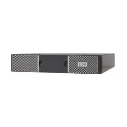
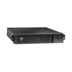
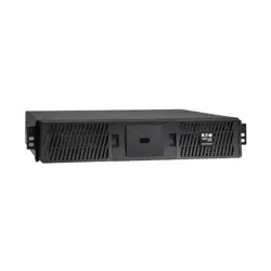
BP48VRXLTAA
BP72VRXLTAA
Extended Battery Module
WEBCARDLXE UPS Web Management Accessory Card SNMP Remote Monitoring HTML5
4 Eaton Tripp Lite Series SmartPro TAA User Guide 614-09404—Rev 01
22..33 RReeaarr PPaanneellss
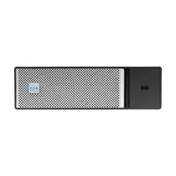
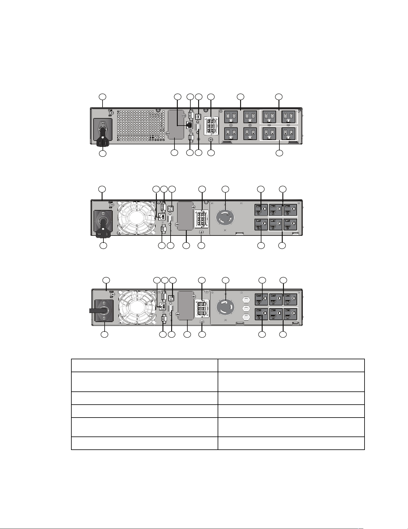
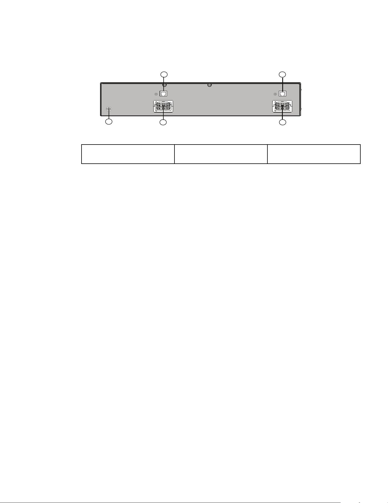
Figure 1. SMART1500RXLTAA
1
2
3
4
5
67
8
9
10
11
12
4
Figure 2. SMART2200RXLTAA
2 4
12
1 358
1011
43
9
67 3
Figure 3. SMART3000RXLTAA
1 358
1011
43
2
4
12
967 3
Table 5. Back Panel Options
① UPS ⑦ Relay output contact
② Input AC power source ⑧ Connector for ROO (Remote ON/OFF) control and RPO
(Remote Power Off)
③ Primary group (critical equipment) ⑨ Slot for optional communication card
④ Outlet group (programmable outlets) ⑩ Connector for additional battery module
⑤ USB communication ports ⑪ Connector for automatic recognition of an additional battery
module
⑥ RS232 communication port ⑫ Ground screw
Rear Panels

Eaton Tripp Lite Series SmartPro TAA User Guide 614-09404—Rev 01 7
CChhaapptteerr 33 IInnssttaallllaattiioonn
33..11 IInnssppeeccttiinngg tthhee eeqquuiippmmeenntt
If any equipment has been damaged during shipment, keep the shipping cartons and packing materials for the
carrier or place of purchase and file a claim for shipping damage. If you discover damage after acceptance, file a
claim for concealed damage. For pluggable equipment, the socket outlet shall be installed near the equipment
and shall be easily accessible.
To file a claim for shipping damage or concealed damage:
1. File with the carrier within 15 days of receipt of the equipment;
2. Send a copy of the damage claim within 15 days to your service representative.
!
IMPORTANT
Check the battery recharge date on the shipping carton label. If the date has passed and the batteries were
never recharged, do not use the UPS. Contact your service representative.
Table 7. Package content
Verify that the following additional items
are included with the UPS:
1. UPS
13. Connection cable to AC power source
15. RS232 communication cable
16. USB communication cable
17. Safety instructions
18. Quick start
20. Rack kit for 19-inch 4-post enclosures
21. Two supports for tower position (tower
feet)
WEBCARDLXE (optional)
CONFIG
STATUS
RESET
8 Eaton Tripp Lite Series SmartPro TAA User Guide 614-09404—Rev 01
33..22 RReeccoommmmeennddeedd PPoossiittiioonnss
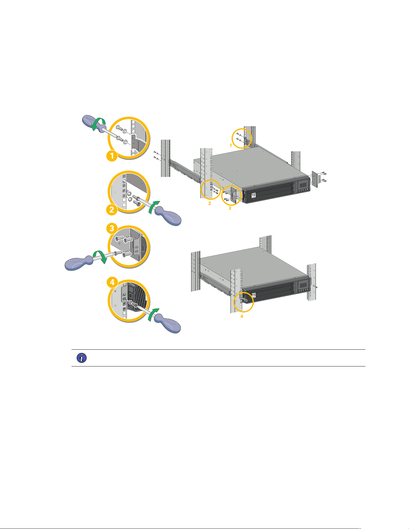
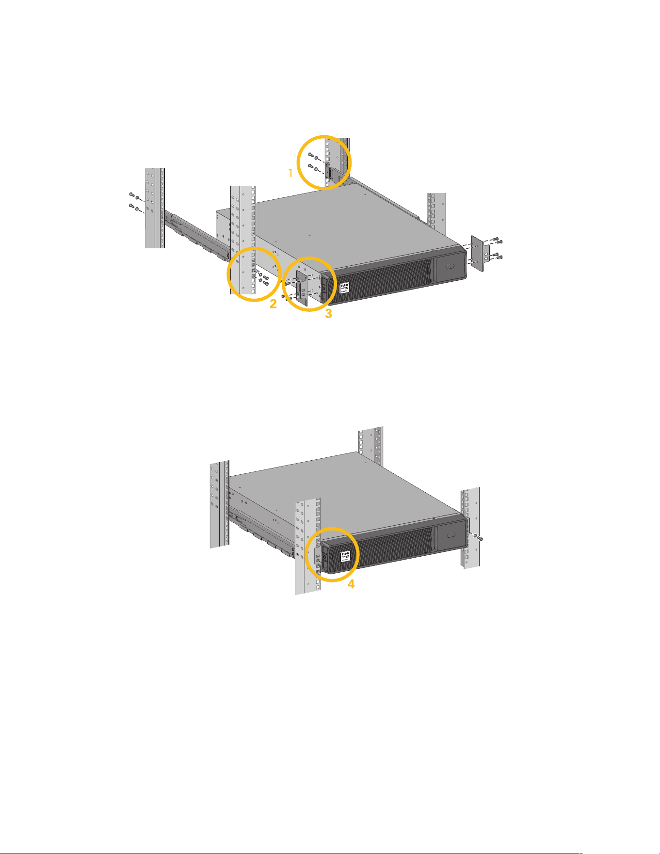
IInnssttaallllaattiioonn iinn rraacckk ppoossiittiioonn
Follow steps 1 to 4 for module mounting on the rails.
Figure 5. Rack Installation Steps
NOTE The rails and necessary hardware are supplied by Eaton.
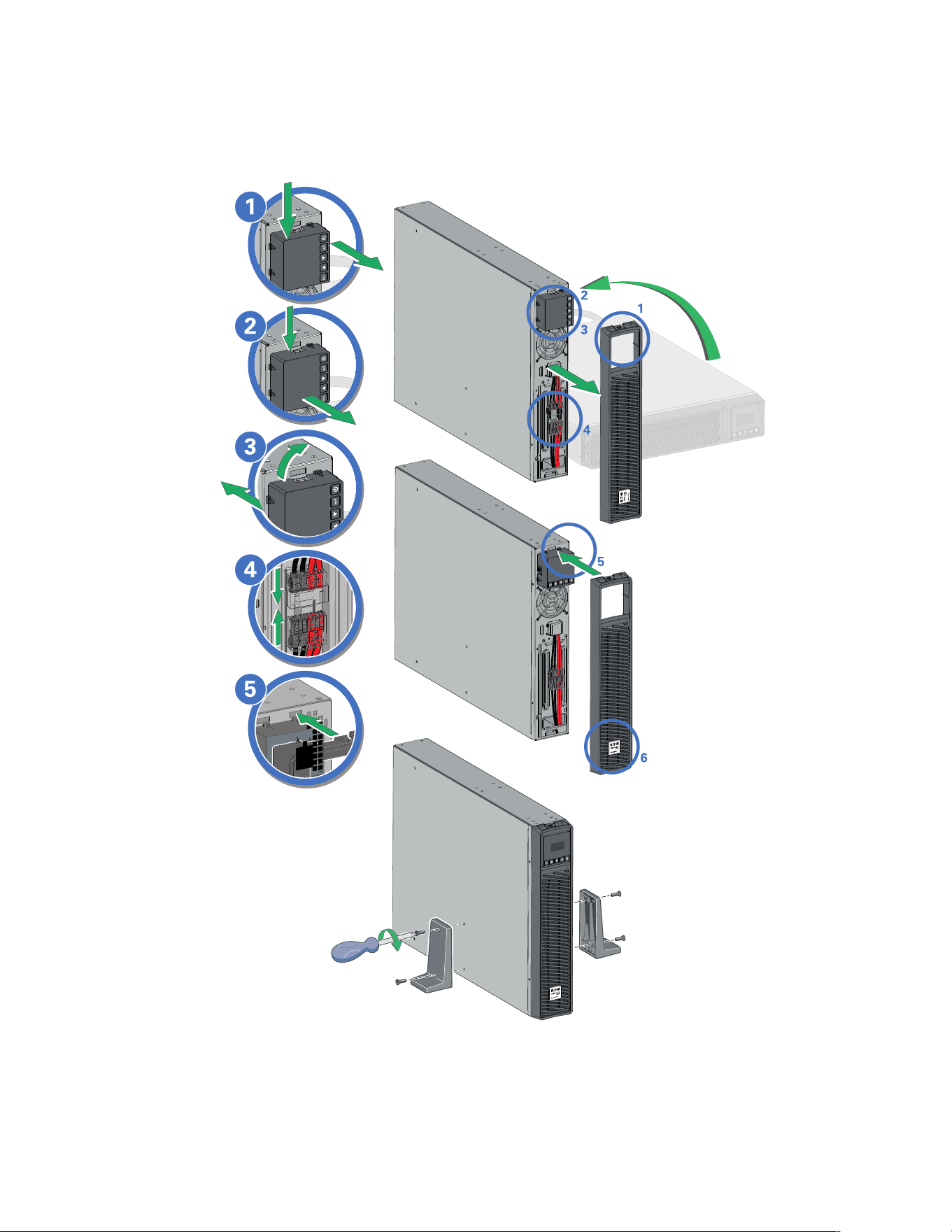
IInnssttaallllaattiioonn iinn ttoowweerr ppoossiittiioonn
If you ordered other UPS accessories, refer to specific user manuals to check the tower installation
with the UPS.
To install the UPS:
Place the UPS on a flat, stable surface in its final location. Always keep 6" or 150 mm of free space behind the
UPS rear panel for ventilation.
If installing additional EBM, place them next to the UPS in their final location.
Follow steps 1 to 5 to adjust the orientation of the LCD panel and of the logo.
Recommended Positions

10 Eaton Tripp Lite Series SmartPro TAA User Guide 614-09404—Rev 01
33..33 CCoonnnneeccttiinngg tthhee IInntteerrnnaall BBaatttteerryy
Figure 7. Internal Battery Connection
A small amount of arcing may occur when connecting the internal batteries. This is normal and will not harm
personnel. Connect the cables quickly and firmly.
1. Remove the front panel by pressing on both sides of the panel.
2. Connect the two battery connectors together.
3. Replace the front panel.
Connecting the Internal Battery
Eaton Tripp Lite Series SmartPro TAA User Guide 614-09404—Rev 01 11
33..44 EEBBMM CCoonnnneeccttiioonn
Figure 8. Tower Battery Connections
A small amount of arcing may occur when connecting an EBM to the UPS. This is normal and will not harm
personnel. Insert the EBM cable into the UPS battery connector quickly and firmly.
1. Attach the UPS and the EBMs to each other using the supplied mounting plate. Up to 4 EBMs may be
connected to the UPS.
2. Connect the EBMs power cable and the attached battery detection cable as shown in the picture.
3. Verify that the EBM connections are tight and that adequate bend radius and strain relief exist for each
cable.
A small amount of arcing may occur when connecting an EBM to the UPS. This is normal and will not harm
personnel. Insert the EBM cable into the UPS battery connector quickly and firmly.
To increase stability, it is preferable to place the EBM below the UPS.
EBM Connection
Eaton Tripp Lite Series SmartPro TAA User Guide 614-09404—Rev 01 13
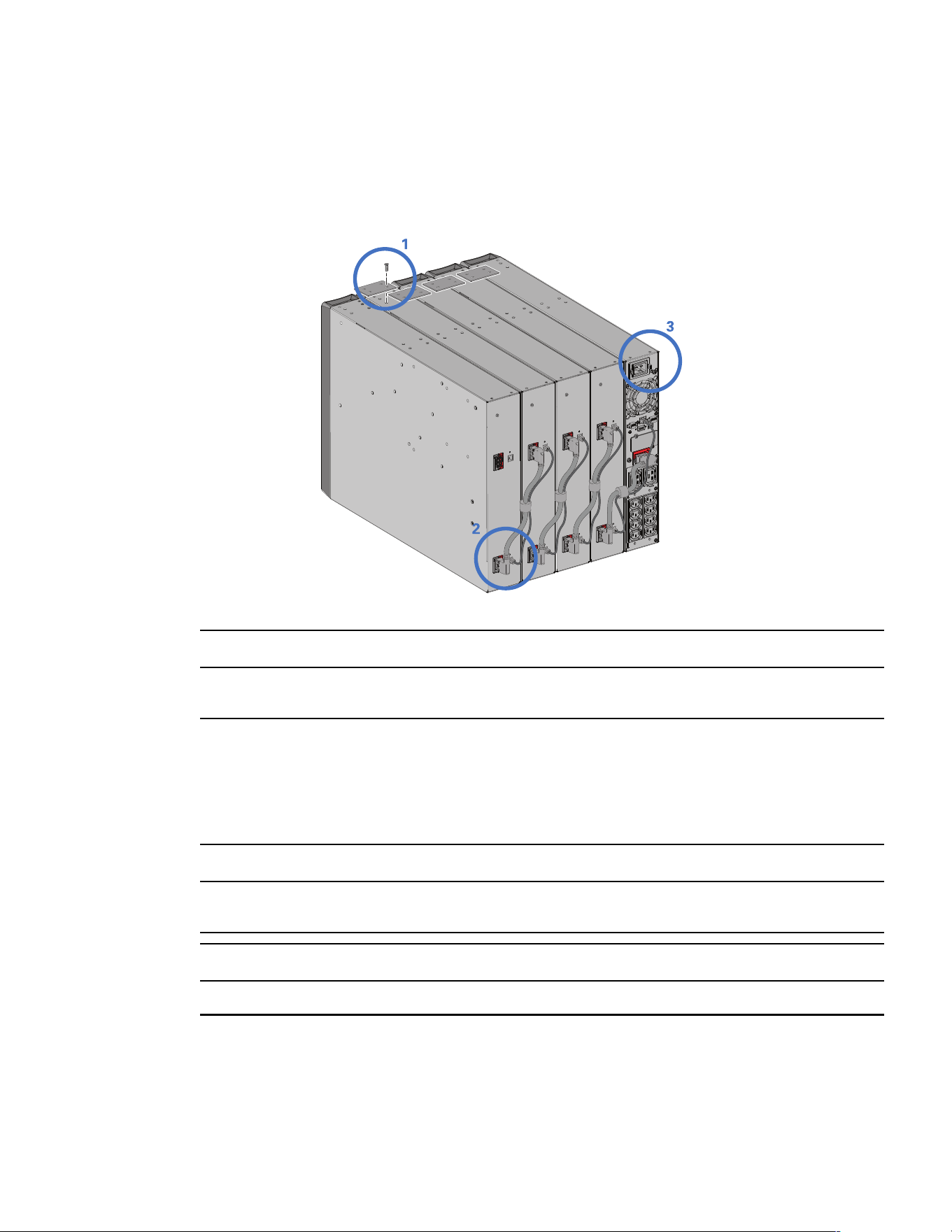
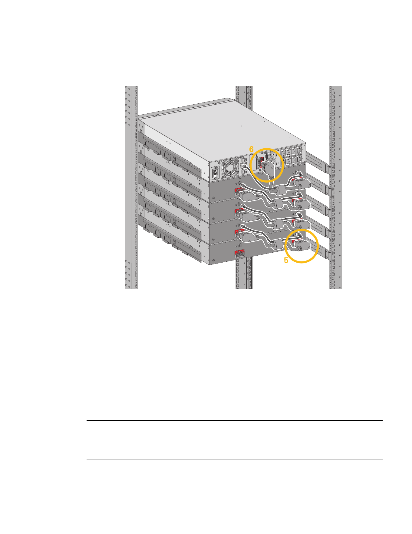
Figure 9. Rack EBM Installation and Connection (Continued)
1. Fix the rail on the back of the rack.
2. Fix the rail on the front of the rack using the two holes at the bottom.
3. Fix the ears plate to the UPS.
4. Place the UPS on the rails and fix the ears plate to the top hole of the rail.
5. Connect the EBM power cable as shown in the picture.
6. Connect the RJ45 battery detection cable of the first EBM between the EBM and the UPS connector "Batt
detection" (11). For any additional EBM, connect the battery detection cable to the previous EBM.
Verify that the EBM connections are tight and that adequate bend radius and strain relief exist for each
cable.
33..55 UUPPSS CCoonnnneeccttiioonn
Check that the indications on the name plate located on the back of the UPS correspond to the AC-power
source and the true electrical consumption of the total load.
UPS Connection

14 Eaton Tripp Lite Series SmartPro TAA User Guide 614-09404—Rev 01
1. Connect the UPS input cable (13) to the AC power source.
2. Connect the loads to the UPS. It is preferable to connect the priority loads to the outlets marked (3) and the
non-priority loads to the outlets Group1, Group2 (4) that can be programmed.programmed.
For the SmartPro2200 / 3000 models, connect any high- power devices or matching Power Distribution
Unit (PDU) to the L5-20R or L5-30R outlet.
3. To program shutdown and startup of the Group1 and Group2 outlets in order to extend battery runtime and
perform scheduled shutdowns, please see the XREF "In/Out settings" section.
UPS Connection
Eaton Tripp Lite Series SmartPro TAA User Guide 614-09404—Rev 01 15
CChhaapptteerr 44 IInntteerrffaacceess aanndd CCoommmmuunniiccaattiioonn
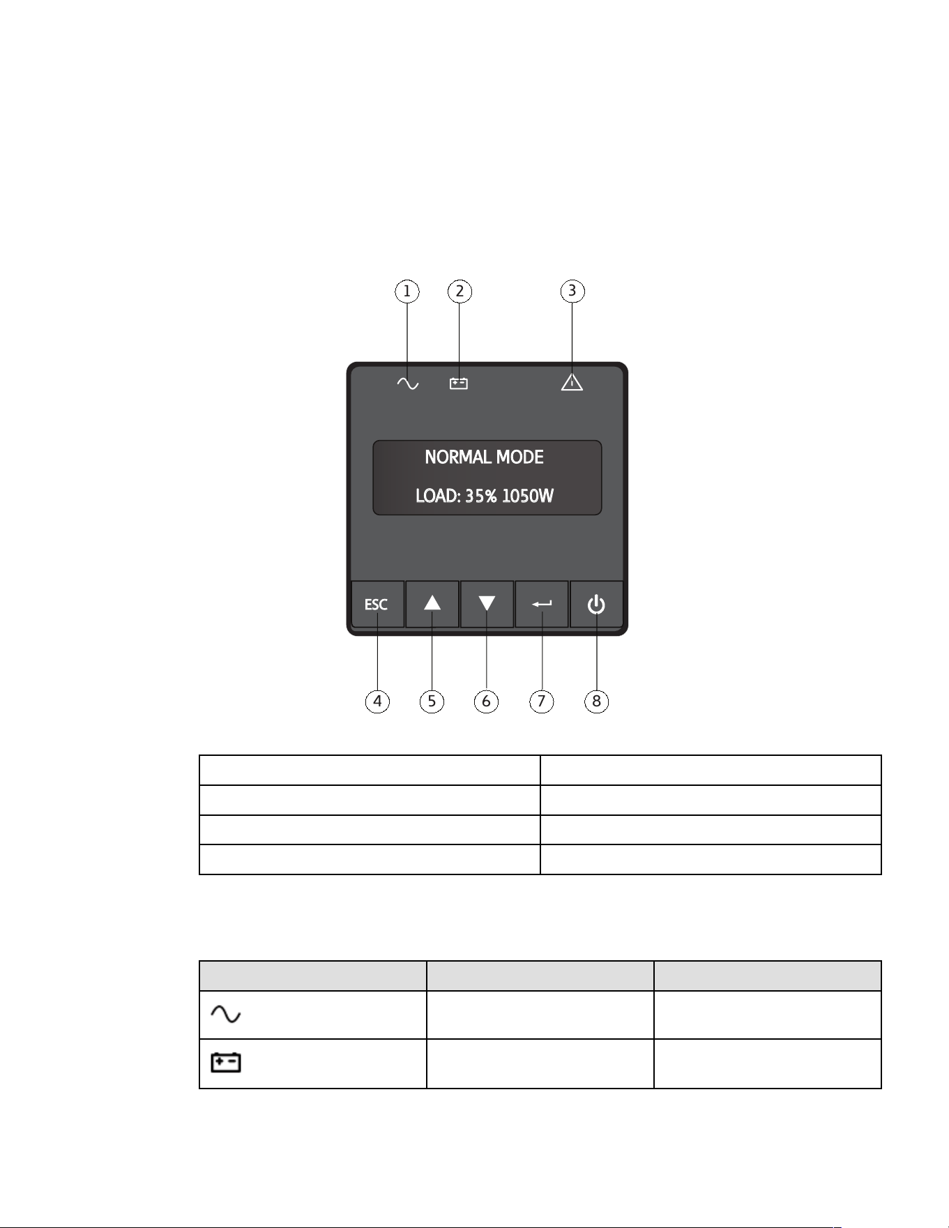
44..11 CCoonnttrrooll ppaanneell
The screen provides useful information about the UPS itself, load status, events, measurements and settings.
Figure 10. Control Panel Details
NORMAL MODE
LOAD: 35% 1050W
ESC
1
2
3
4 5 6 7 8
① Power ON indicator (green) ⑤ Up
② Power ON indicator (green) ⑥ Down
③ Alarm Indicator (red) ⑦ Enter
④ Escape ⑧ On/Off button
The following table shows the indicator status and description :
Table 8. LED Indicator Details
Indicator Status
Description
Green
On
The UPS is "On" and the load is
protected.
Orange
On
The UPS is in battery mode and the load
is protected.
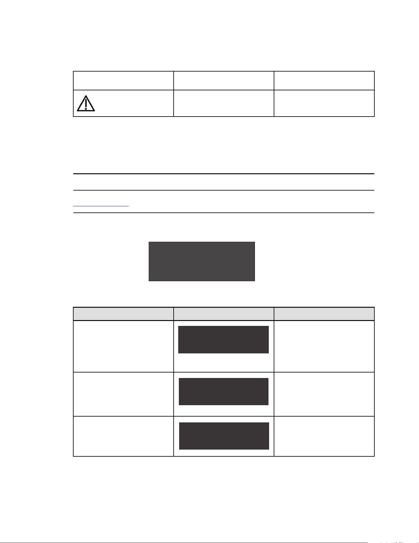
16 Eaton Tripp Lite Series SmartPro TAA User Guide 614-09404—Rev 01
Table 8. LED Indicator Details (Continued)
Flashing
The battery voltage is below the warning
level.
Red
On
The UPS has an active alarm or fault. See
troubleshooting page for additional
information.
44..22 LLCCDD DDeessccrriippttiioonn
The LCD screen has 2 lines, each line may show 16 characters maximum. The first line shows UPS mode,
which may be standby mode, normal mode, battery mode, backup end mode or fault mode. The second line
shows measures. The backlight LCD automatically dims after 5 minutes of inactivity. Press any button to
restore the screen.
If fault or alarm appears, the first line of LCD will cycle between fault/alarm message and UPS mode, see
7.1 Troubleshooting for additional information.
Figure 11. LCD Screen — Example
NORMAL MODE
LOAD:35% 1050W
Table 9. LCD Screen – Display Details
Screen Battery area display Bottom row values
1st Screen (home / default screen):
Load percentage and Watt.
LOAD: xxx% xxxxW
UPS MODE
The LOAD data screen specifies the
amount of power that connected
equipment is currently using in terms of
percentage and Watt.
Load %, 0 decimal.
Load W , 0 decimals.
2nd Screen:
Load percentage and VA.
LOAD: xxx% xxxxVA
UPS MODE
The OUTPUT LOAD LEVEL screen
indicates the load percentage and VA
output load level.
Load % , 0 decimals.
Load VA , 0 decimals.
3rd Screen:
Output load power factor
LOAD PF: x. xx
UPS MODE
The OUTPUT LOAD POWER FACTOR
screen indicates the power factor of
connected equipment.
2 decimal.
LCD Description
Eaton Tripp Lite Series SmartPro TAA User Guide 614-09404—Rev 01 17
Table 9. LCD Screen – Display Details (Continued)
4th Screen:
Input voltage and frequency
IN: xxxV xx. xHZ
UPS MODE
The INPUT VOLTAGE & FREQUENCY
screen displays current data.
Input voltage: 0 decimal.
Input frequency HZ,1 decimal.
5th Screen:
Output voltage and frequency
OUT: xxxV xx. xHZ
UPS MODE
The OUTPUT VOLTAGE & FREQUENCY
screen displays current data.
Output voltage: 0 decimal.
Output frequency HZ,1 decimal.
6th Screen:
Battery voltage and charge percentage
BAT: xx. xV xxx%
UPS MODE
The BATTERY voltage screen tracks the
charge level of your connected battery
bank in terms of voltage and charge
percentage.
Battery voltage:1 decimal.
Charge percentage:0 decimal.
7th Screen:
Remaining battery runtime
RUNTIME: xxxMIN
UPS MODE
The RUNTIME remaining screen tracks
the approximate minutes of runtime
available under the current loading and
battery pack configuration. The runtime
value will automatically re-calculate as
connected equipment power consumption
changes.
0 decimal.
8th Screen:
External battery quantity
EBM: x
UPS MODE
The EBM screen display external battery
quantity. This screen is only for long time
model.
0 decimal.
9th Screen:
Remaining watts of UPS
REMAIN W: x. xxKW
UPS MODE
The REMAIN WATTS screen tracks the
remaining capacity of the UPS in kilowatt
2 decimals.
10th Screen:
Demand energy
DEMAND E: x. xxKWH
UPS MODE
The DEMAND ENERGY screen offers
continuous data on the KWh(kilowatt-
hour) that connected equipment has
consumed in the last one-hour period.
2 decimals.
The following table describes the status information provided by the UPS :
Table 10. System Operational Status Details
Operation status Possible cause Action
Standby mode
The UPS is OFF, waiting for start-up
command from user
Equipment is not power until button
is
pressed during start up and the green "normal
mode" LED indicator is illuminated.
LCD Description

18 Eaton Tripp Lite Series SmartPro TAA User Guide 614-09404—Rev 01
Table 10. System Operational Status Details (Continued)
Normal mode
The UPS is operating normally.
The UPS is powering and protecting the
equipment.
Battery Mode
One beep every 10 seconds
A utility failure has occurred and the
UPS is in Battery mode.
The UPS is powering the equipment with
battery power. Prepare your equipment for
shutdown.
End of backup time
1 beep every 3 seconds
The UPS is in Battery mode and the
battery is running low.
This warning is approximate, and the actual
time to shutdown may vary significantly.
Depending on the UPS Load, the "Battery Low"
warning may occur before the battery reaches
20% capacity remaining.
Fault Mode
Some fault has happened to the UPS.
Action may be needed.
See 7.1 Troubleshooting for additional
information.
44..33 DDiissppllaayy FFuunnccttiioonnss
Press the Enter ( ) button to activate the menu options. Use the two middle buttons ( and ) to scroll through
the menu structure. Press the Enter (
) button to select an option. Press the (
ESC) button to cancel or return
to the previous menu.
Table 11. Menu Map for Display Functions
Main menu Submenu Display information or Menu function
CONTROL
BATTERY TEST
Starts a manual battery test(possible if load>10% and battery
>80%).
RESET FAULT ST Reset fault state.
CLEAR EVENT LOG Clears the faults and events stored.
RESET KWH USED
Reset the power used.
FACTORY SETT
Restore factory settings.
LOCAL SETTING
LANGUAGE
Sets product general parameters, see 4.4 User Settings
AUDIBLE ALARM
Sets input and output parameters, see 4.4 User Settings
IN/OUT SETTING
OUTPUT VOLTAGE
Select output voltage through this submenu.
INPUT THRESHOLD
Input threshold can be set to normal or extended through this
menu.
SENSITIVITY
Sensitivity can be set to high or low through this menu.
OVRLOAD PREALARM
Overload pre-alarm can be set through this menu.
ON/OFF SETTING
COLD START
Cold start can be enabled or disabled through this menu.
AUTO RESTART
Auto restart can be enabled or disabled through this menu.
AUTO START
Auto start can be enabled or disabled through this menu.
SLEEP MODE
Sleep mode can be enabled or disabled through this menu.
Display Functions

Eaton Tripp Lite Series SmartPro TAA User Guide 614-09404—Rev 01 19
Table 11. Menu Map for Display Functions (Continued)
Main menu Submenu Display information or Menu function
SITE WIRING FLT
Site wiring fault can be enabled or disabled through this
menu.
BATTERY SETTING
AUTO BAT TEST
Auto battery test period can be set through this menu.
RESTART LEVEL
Restart battery level can be set through this menu.
BAT LOW LEVEL
Battery low percentage can be set through this menu.
BAT LOW TIME
Battery low remaining time can be set through this menu.
COM SETTING
REMOTE ON/OFF
Select input signal function for REMOTE ON/OFF.
REMOTE PWR OFF
Select input signal function for REMOTE PWR OFF.
INPUT DB9-4
Select input signal function for INPUT DB9-4.
OUTPUT RELAY
Select output signal function for OUTPUT RELAY.
OUTPUT DB9-1
Select output signal function for OUTPUT DB9-1.
OUTPUT DB9-7
Select output signal function for OUTPUT DB9-7.
OUTPUT DB9-8
Select output signal function for OUTPUT DB9-8.
EVENT LOG
Event log has utmost 50 items to show what happened.
IDENTIFICATION This menu shows IDENTIFICATION information.
44..44 UUsseerr SSeettttiinnggss
The following table displays the options that can be changed by the user.
Table 12. User Settings
Submenu Available settings Default settings
LOCAL SETTING
LANGUAGE ENGLISH FRANCAIS ESPANOL ENGLISH
AUDIBLE ALARM
ENABLED
DISABLED ON BAT
ALWAYS DISABLED
ENABLED
IN/OUT SETTING
OUTPUT VOLTAGE
[200 V] [208 V] [220 V] [230 V]
[240 V]
[208 V]
INPUT THRESHOLD NORMAL EXTENDED NORMAL
SENSITIVITY HIGH LOW HIGH
OVRLOAD PREALARM
[50%-105%, step is 5%.
105%
ON/OFF SETTING
COLD START ENABLED DISABLED ENABLED
AUTO RESTART ENABLED DISABLED ENABLED
AUTO START ENABLED DISABLED DISABLED
SLEEP MODE ENABLED DISABLED ENABLED
User Settings

20 Eaton Tripp Lite Series SmartPro TAA User Guide 614-09404—Rev 01
Table 12. User Settings (Continued)
Submenu Available settings Default settings
SITE WIRING FLT ENABLED DISABLED DISABLED
BATTERY SETTING
AUTO BAT TEST NO TEST MONTHLY MONTHLY
RESTART LEVEL
0%-100%, step is 5%.
0%
BAT LOW LEVEL
0%-100%, step is 10%.
0%
BAT LOW TIME
0MIN-60MIN, step is 3MIN
3MIN
COM SETTING
REMOTE ON/OFF
NO
ROO
RPO
BLD.ALARM
SHUTDOWN CMD
NO
REMOTE PWR OFF
NO
ROO
RPO
BLD.ALARM
SHUTDOWN CMD
NO
INPUT DB9-4
NO
ROO
RPO
BLD.ALARM
SHUTDOWN CMD
NO
OUTPUT RELAY
ON BATTERY
LOW BATTERY
BATTERY FAULT
UPS OK
LOAD PROTECTED
LOAD POWERED
GENERAL ALARM
OVRLOAD PREALARM
BAT DISCONN
BATTERY FAULT
OUTPUT DB9-1
ON BATTERY
LOW BATTERY
BATTERY FAULT
UPS OK
LOAD PROTECTED
LOAD POWERED
GENERAL ALARM
OVRLOAD PREALARM
BAT DISCONN
LOW BATTERY
User Settings

Eaton Tripp Lite Series SmartPro TAA User Guide 614-09404—Rev 01 21
Table 12. User Settings (Continued)
Submenu Available settings Default settings
OUTPUT DB9-7
ON BATTERY
LOW BATTERY
BATTERY FAULT
UPS OK
LOAD PROTECTED
LOAD POWERED
GENERAL ALARM
OVRLOAD PREALARM
BAT DISCONN
UPS OK
OUTPUT DB9-8
ON BATTERY
LOW BATTERY
BATTERY FAULT
UPS OK
LOAD PROTECTED
LOAD POWERED
GENERAL ALARM
OVRLOAD PREALARM
BAT DISCONN
ON BATTERY
44..55 CCoommmmuunniiccaattiioonn PPoorrttss
Table 13. RS232/USB Communication Port Connection Steps
1. Connect the RS232 (15) or USB (16) communication cable to the
serial or USB port on the computer equipment.
2. Connect the other end of the communication cable (15) or (16) to
the USB (5) or RS232 (6) communication port on the UPS.
The UPS can now communicate with Eaton Tripp Lite Series
power management software.
You can improve the remote monitoring and power management of
the UPS by adding a communication card compatible with the
SmartPro product, see paragraph
4.6 UPS Remote Control Functions.
Communication Ports

22 Eaton Tripp Lite Series SmartPro TAA User Guide 614-09404—Rev 01
Table 14. RS232 Communication Port Contact Details
Pin Signal Direction Function
Contact characteristics (optocoupler)
• Voltage: 48 V DC max
• Current: 25 mA max
• Power: 1.2 W
1
Bat low Output Low Battery Output
2
TxD
Output
Transmit to external device
3
RxD Input Receive from external device
4
I/P SIG Input
-
5
GNDS
-
Signal Common tied to chassis
6
PNP Input Plug and Play
7
UPS OK Output UPS OK
8
BAT mode Output UPS on battery mode
9
+5V
Output Power supply for external signal or
options
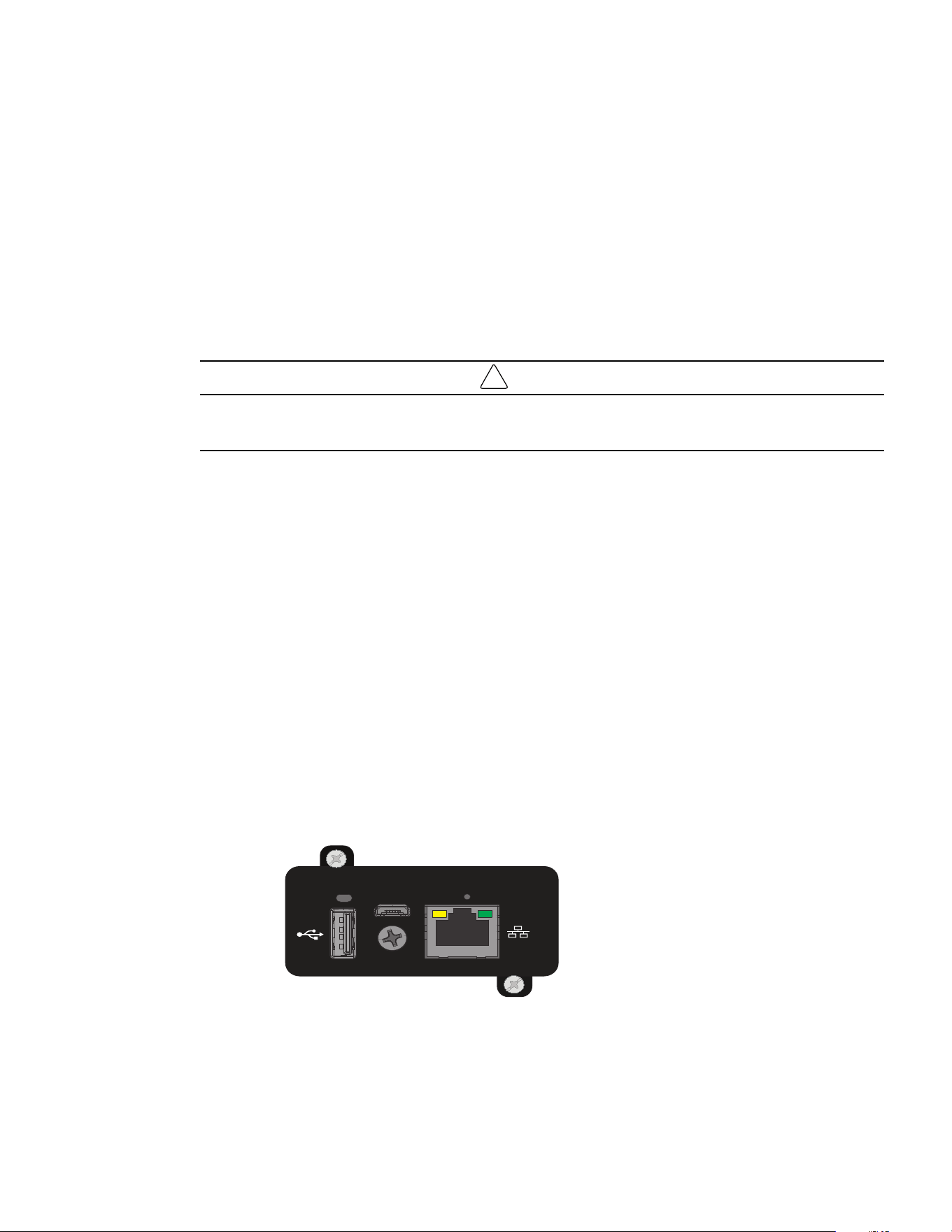
Table 15. Communication Card Installation Steps
Installation of the communication cards
Accessory Slot: Remove the small cover panel from this slot to
install optional accessories to remotely monitor and control your
UPS. Refer to your accessory’s manual for installation
instructions. Contact tripplite.eaton.com for more information,
including a list of available SNMP, network management and
connectivity products.
NOTE Select models include a pre installed network
management card. For these models, refer to the
management card accessory user manual included with
your UPS for connection, configuration and complete
operating instructions.
44..66 UUPPSS RReemmoottee CCoonnttrrooll FFuunnccttiioonnss
CCoonnnneeccttiivviittyy ccaarrddss
Connectivity cards allow the UPS to communicate in a variety of networking environments and with different
types of devices. The SmartPro models have one available communication bay for the following connectivity
card:
• Network card (WEBCARDLXE) : Operate any compatible UPS system or PDU as a managed device on your
network. Monitor and control the device using an SNMP network management platform, web browser, SSH or
Telnet.
UPS Remote Control Functions
Eaton Tripp Lite Series SmartPro TAA User Guide 614-09404—Rev 01 23
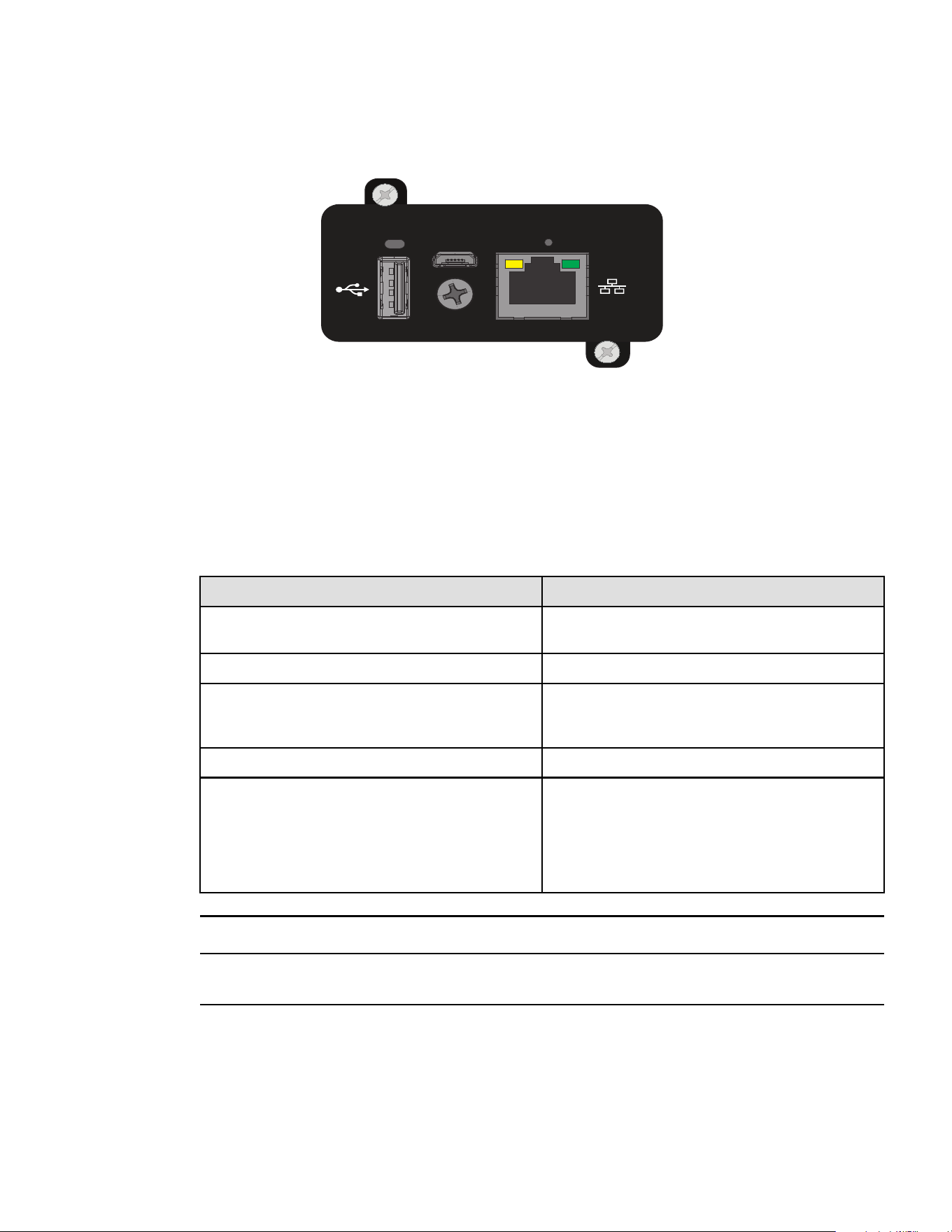
Figure 12. Network Card
CONFIG
STATUS
RESET
PPrrooggrraammmmaabbllee ssiiggnnaall iinnppuuttss
The SmartPro incorporates several programmable signal inputs: one Remote Power Off (RPO) input terminal,
one Remote On/Off (ROO) input terminal, one RS-232 input (pin-4).
Signal inputs can be configured (see Settings > Comm settings > Signal Input) to have one of the following
functions:
Table 16. Programmable Signal Input Details
Function Description
No
No function. (Please choose a function if you want to use input
signal.)
RPO Remote Power off (RPO) is used to shutdown the UPS remotely.
ROO Remote On/Off allows remote action of a button or other
interface to switch On/ Off the UPS. (Cold start is prohibited
while using the ROO function.)
Building alarm Active input generates an alarm "building alarm".
Shutdown commands Active input turns UPS output (or outlet groups) off after a user
defined shutdown delay but keeps on charging batteries
according to a selected charging scheme; inactive input does
not abort shutdown countdown. Depending on the "Restart"
parameter (see Settings > Comm Settings > Shutdown
commands) the unit may startup automatically.
Signal inputs have no function by default; please choose a function through the LCD (Settings > Com settings
> Input signals).
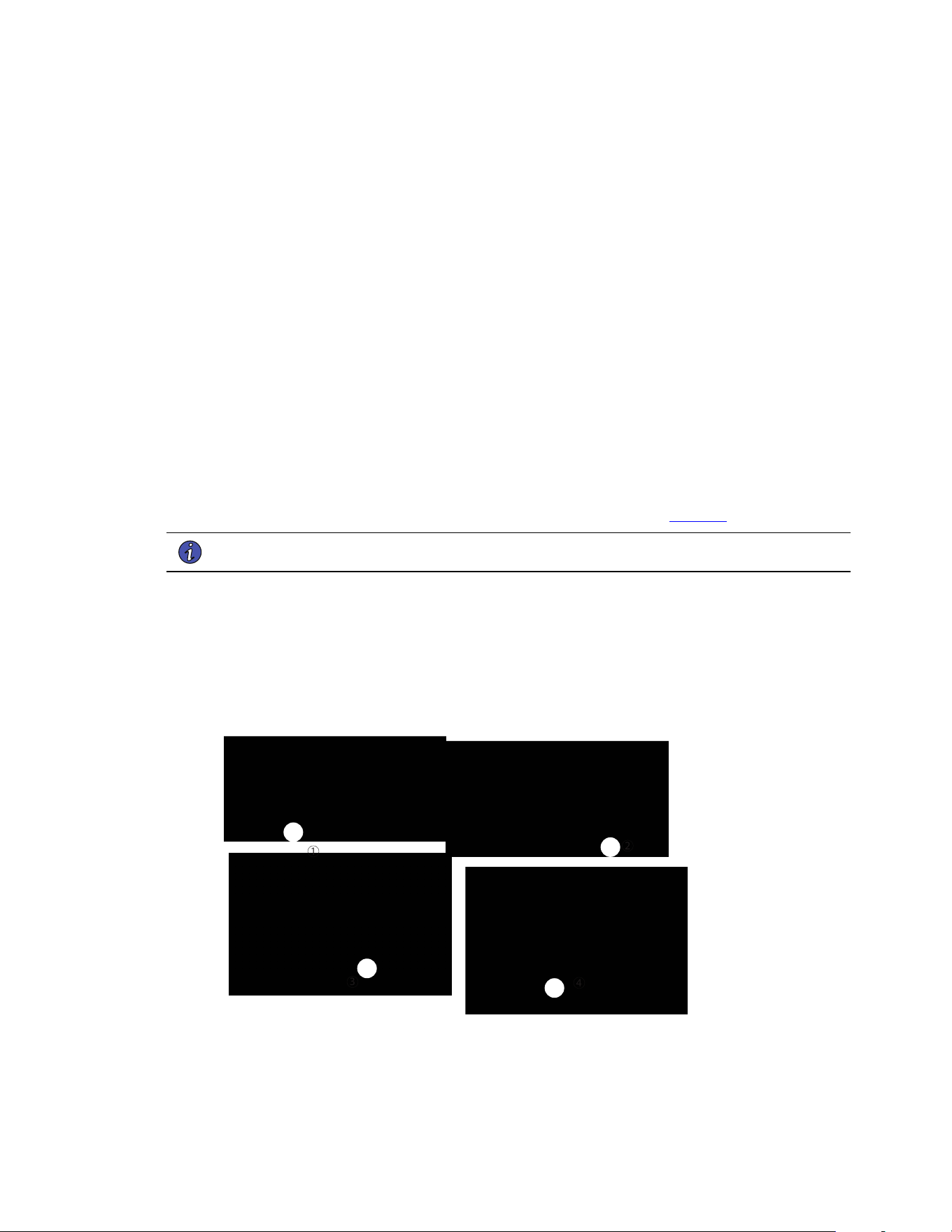
See the following two examples of system configuration with the RPO terminal used as RPO function and the
ROO terminal use as ROO function:
UPS Remote Control Functions
24 Eaton Tripp Lite Series SmartPro TAA User Guide 614-09404—Rev 01
RReemmoottee PPoowweerr OOffff ((RRPPOO))
RPO is used to shutdown the UPS remotely when the contact is open. This feature can be used for shutting
down the load and the UPS by thermal relay, for example, in the event of room over temperature. When RPO is
activated, the UPS turns 25 off the output and shuts down all power converters immediately (except for logic
power). The UPS remains "ON" to alarm the fault.
The RPO circuit is a safety extra low voltage (SELV) circuit. This circuit must be separated from any hazardous
voltage circuits by reinforced insulation.
• The RPO must not be connected to any utility connected circuits. Reinforced insulation to the utility is
required. The RPO switch must be a dedicated latching-type switch not tied into any other circuit. The RPO
signal must remain active for at least 250 ms for proper operation.
• To ensure the UPS stops supplying power to the load during any mode of operation, the input power must
be disconnected from the UPS when the Remote Power Off function is activated.
Table 17. RPO Connections Detail
RPO Comments
Connector type Terminal, 14 AWG Maximum wires
Terminal rating
60 V DC/30 V AC 20 mA max
RReemmoottee OOnn//OOffff ((RROOOO))
• Remote On/Off allows remote action of button to switch On/Off the UPS.
• When contact changes from open to closed, the UPS is switched-on (or stays On).
• When contact changes from closed to open, the UPS is switched-off (or stays Off).
• On/Off control via button has priority over the remote control.
The ROO function is only active after the first use of the "Remote OFF" function.
ROO Comments
Connector type Terminal, 14 AWG Maximum wires
Terminal rating 60 V DC/30 V AC 20 mA max
RReemmoottee ccoonnttrrooll ccoonnnneeccttiioonn aanndd tteesstt
1. Check the UPS is shut down and the electrical supply network disconnected.
UPS Remote Control Functions

Eaton Tripp Lite Series SmartPro TAA User Guide 614-09404—Rev 01 25
2. Remove RPO connector from the UPS by removing the screws.
3. Connect a normally closed volt-free contact between the two pins of connector.
Contact open: shut down of UPS.
To return to normal operation, deactivate the external remote
shut down contact and restart the UPS from the front panel.
4. Plug the RPO connector into the back of the UPS and fix the screws.
5. Connect and restart the UPS according to the previously described procedures.
6. Activate the external remote shut down contact to test the function
Always test the RPO function before applying your critical load to avoid accidental load loss.
PPrrooggrraammmmaabbllee ssiiggnnaall oouuttppuuttss
The SmartPro incorporates several programmable signal outputs: one relay output and two optocoupler outputs
(DB9 pins 1 and 8). Signal outputs can be configured (see Settings > Comm settings > Output Signals) to report
the following information:
Table 18. Programmable Signal Outputs Details
Signal Default Assignment Description
On battery (On Bat)
DB9-Pin 8 UPS is in battery mode
Low battery (Low Bat)
DB9-Pin 1 UPS is in battery mode and has reached the low
battery alarm threshold
Battery fault
(1) Relay output
Battery fault
UPS OK DB9-Pin 7
Load is powered with no alarm (from inverter or
bypass)
Load protected
-
UPS is on inverter, with no alarm and ready to go
to battery
Load powered
-
Load is powered(from inverter or bypass)
General alarm
-
Choose events that will trigger this alarm trough
the LCD (Settings > Comm settings > General
alarm).
For more information on possible events please
look at User settings
OVLD pre-alarm
-
Overload pre-alarm
Bat disconn
-
Battery is disconnected
UPS Remote Control Functions

26 Eaton Tripp Lite Series SmartPro TAA User Guide 614-09404—Rev 01
Figure 13. Relay Output Details
44..77 PPoowweerr AAlleerrtt SSooffttwwaarree
Use with Tripp Lite’s PowerAlert Software and included cables to enable your computer to automatically save
open files and shut down equipment during a blackout. Also use PowerAlert Software to monitor a wide variety
of AC line power and UPS operating conditions. Consult your PowerAlert Software manual or contact Tripp Lite
Customer Support for more information.
44..88 CCyybbeerrsseeccuurriittyy
Eaton is committed to minimizing the Cybersecurity risk in its products and employs cybersecurity best
practices and the latest cybersecurity technologies in its products and solutions, making them more secure,
reliable and competitive for our customers. Eaton also offers Cybersecurity Best Practices whitepapers to its
customers, referenced at www.eaton.com/cybersecurity.
Power Alert Software

Eaton Tripp Lite Series SmartPro TAA User Guide 614-09404—Rev 01 27
CChhaapptteerr 55 OOppeerraattiioonn
55..11 SSttaarrtt--uupp aanndd nnoorrmmaall ooppeerraattiioonn
Check that the indications on the name plate located on the back of the UPS meets to the AC power source
and the true electrical consumption of the total load.
BBaatttteerryy cchhaarrggee
The UPS charges the battery as soon as it is connected to the AC outlet, whether the ON/OFF button is
pressed or not. It is recommended that the UPS be permanently connected to the AC power supply to ensure
the best possible autonomy.
To start the UPS:
1. Verify that the UPS power cord is plugged in.
2. The UPS front panel display illuminates.
3. Press the
button on the UPS front panel for at least two seconds.
4. Check the UPS front panel display for active alarms or notices. Resolve any active alarms before
continuing; if the
indicator is on, do not proceed until all alarms are clear (see 7.1 Troubleshooting ).
Check the UPS status from the front panel to view the active alarms. Correct the alarms and restart if
necessary.
5. Verify that the
indicator illuminates solid, indicating that the UPS is operating normally and any loads
are powered and protected. The UPS should be in Normal mode.
55..22 SSttaarrttiinngg tthhee UUPPSS oonn bbaatttteerryy
Before using this feature, the UPS must have been powered by utility power with output enabled at least once.
Battery start can be disabled. See the "Cold start" setting in .
To start the UPS on battery:
1. When the UPS is disconnected from the AC power source, press the
button on the UPS front panel.
The UPS transfers from Standby mode to Battery mode. The
indicator illuminates solid.
The UPS supplies power to your equipment.
2. Check the UPS front panel display for active alarms or notices besides the "Battery mode" and related
notifications that indicates missing utility power. Resolve any active alarms before continuing. See
7.1 Troubleshooting .
Check the UPS status from the front panel to view the active alarms. Correct the alarms and restart if
necessary.
55..33 UUPPSS sshhuuttddoowwnn
To shut down the UPS:
Press the
button on the front panel for three seconds.

28 Eaton Tripp Lite Series SmartPro TAA User Guide 614-09404—Rev 01
The UPS starts to beep and shows a status of "SHUTTING DOWN...". The UPS then transfers to Standby mode.
55..44 OOppeerraattiinngg mmooddeess
The Eaton® Tripp Lite Series SmartPro TAA front panel indicates the UPS status through the UPS indicators
located above the LCD screen.
NNoorrmmaall mmooddee
When the green sinewave symbol is illuminated, the UPS is providing protected AC power output. The UPS
monitors and charges the batteries as needed and provides power protection to your equipment.
BBaatttteerryy mmooddee
When the UPS is operating during a power outage, the alarm beeps once every ten seconds and the indicator
illuminates solid. The necessary energy is provided by the battery.
When the utility power returns, the UPS transfers to Normal mode operation while the battery recharges. If
battery capacity becomes low while in Battery mode, the audible alarm beeps once every three seconds.
This warning is approximate, and the actual time to shutdown may vary significantly; gracefully shutdown all
applications on connected equipment due to imminent UPS shutdown.
When utility power is restored after the UPS shuts down, the UPS automatically restarts.
LLooww--bbaatttteerryy wwaarrnniinngg
• The
indicator illuminates solid.
• The audio alarm beeps every three seconds.
The remaining battery power is low. Shut down all applications on the connected equipment because
automatic UPS shutdown is imminent.
EEnndd ooff bbaatttteerryy bbaacckkuupp ttiimmee
• LCD displays "BACKUP END MODE".
• All the LEDs go OFF.
• The audible alarm stops.
55..55 RReettuurrnn ooff AACC iinnppuutt ppoowweerr
Following an outage, the UPS restarts automatically when AC input power returns (unless the restart function
has been disabled) and the load is supplied again.
55..66 CCoonnffiigguurriinngg BBaatttteerryy SSeettttiinnggss
AAuuttoommaattiicc bbaatttteerryy tteesstt
Automatic battery tests are done every month.
During the test, the UPS transfers to Battery mode and discharges the batteries for 10 seconds under load.
Battery mode is not displayed and battery low alarm does not activate during a battery test.
The battery test may be postponed due to bad conditions, or failed if battery is not ok.
LLooww bbaatttteerryy wwaarrnniinngg
During discharge, the low battery alarm is activated if the remaining runtime goes below 3 minutes or less than
the setting capacity threshold (0% by default).
Operating modes

Eaton Tripp Lite Series SmartPro TAA User Guide 614-09404—Rev 01 29
This threshold can be modified.
EExxtteerrnnaall bbaatttteerryy sseettttiinngg
The number of Extended Battery Module is automatically detected.
DDeeeepp ddiisscchhaarrggee pprrootteeccttiioonn
This setting is recommended to avoid damaging the battery. Warranty is void if deep discharge protection is
disabled.
55..77 RReettrriieevviinngg tthhee eevveenntt aanndd ffaauulltt lloogg
To retrieve the event and fault log through the display:
1. Press any button to activate the menu options, then select event log.
2. Scroll through the listed events and faults.
Retrieving the event and fault log


Eaton Tripp Lite Series SmartPro TAA User Guide 614-09404—Rev 01 31
CChhaapptteerr 66 UUPPSS MMaaiinntteennaannccee
66..11 EEqquuiippmmeenntt CCaarree
For the best preventive maintenance, keep the area around the equipment clean and dust free. If the
atmosphere is very dusty, clean the outside of the system with a vacuum cleaner.
For full battery life, keep the equipment at an ambient temperature of 25 °C (77 °F).
The batteries are rated for a 3-5 year service life. The length of service life varies, depending on the frequency
of usage and ambient temperature (life divided by 2 each 10 °C above 25 °C).
If the UPS requires any type of transportation, verify that the UPS is turned off.
Batteries used beyond expected service life will often have severely reduced runtimes. Replace batteries at
least every 4 years to keep units running at peak performance.
Batteries runtime will be reduced at low temperature (below 10 °C).
66..22 SSttoorriinngg tthhee EEqquuiippmmeenntt
If you store the equipment for a long period, recharge the battery every 6 months by connecting the UPS to
utility power. The internal batteries charge to 90% capacity in less than 3 hours. However, Eaton recommends
that the batteries charge for 48 hours after long-term storage.
Check the battery recharge date on the shipping carton label. If the date has passed and the batteries were
never recharged, do not use them. Contact your service representative.
66..33 WWhheenn ttoo RReeppllaaccee BBaatttteerriieess
Eaton Tripp Lite Series UPS batteries have an expected life span of 3-5 years.
After 4 years of operation you should take proactive steps to ensure you replace your batteries for optimal
operation and reliability.
Contact your service representative to order new batteries.
Battery recommended replacement reference can be accessed through the LCD.
66..44 RReeppllaacciinngg BBaatttteerriieess
DO NOT DISCONNECT the batteries while the UPS is in Battery mode.
For battery replacement, follow Eaton Tripp Lite Series instructions provided on tripplite.eaton.com.
Batteries can be replaced easily without turning off the UPS or disconnecting the load.
Consider all warnings, cautions, and notes before replacing batteries.
• Servicing should be performed by qualified service personnel knowledgeable of batteries and required
precautions.
Keep unauthorized personnel away from batteries.
• Batteries can present a risk of electrical shock or burn from high short circuit current.
Observe the following precautions:
1. Remove watches, rings, or other metal objects.
2. Use tools with insulated handles.
32 Eaton Tripp Lite Series SmartPro TAA User Guide 614-09404—Rev 01
3. Do not lay tools or metal parts on top of batteries.
4. Wear rubber gloves and boots.
• When replacing batteries, replace with the same type and number of batteries or battery packs. Contact
your service representative to order new batteries.
• Proper disposal of batteries is required. Refer to your local codes for disposal requirements.
• Never dispose of batteries in a fire. Batteries may explode when exposed to flame.
• Do not open or mutilate the battery or batteries. Released electrolyte is harmful to the skin and eyes and
may be extremely toxic.
• Determine if the battery is inadvertently grounded. If inadvertently grounded, remove source from ground.
Contact with any part of a grounded battery can result in electrical shock. The likelihood of such shock can
be reduced if such grounds are removed during installation and maintenance (applicable to equipment and
remote battery supplies not having a grounded supply circuit).
• ELECTRIC ENERGY HAZARD. Do not attempt to alter any battery wiring or connectors. Attempting to alter
wiring can cause injury.
• Disconnect charging source prior to connecting or disconnecting battery terminals.
RReeppllaacciinngg tthhee IInntteerrnnaall BBaatttteerryy
The internal battery is heavy. Use caution when handling the heavy batteries. See Figure 14 .
NOTE A Phillips head screwdriver is needed to perform this procedure.
1. Pull off the front panel by pressing the tabs on both sides.
2. Disconnect the battery pack by separating the connectors (never pull on the wires).
3. Remove the metal protection cover in front of the battery (three screws).
4. Pull the plastic tab to remove the battery pack and replace it.
Figure 14. Battery Replacement
4
3
2
1
Replacing Batteries

Eaton Tripp Lite Series SmartPro TAA User Guide 614-09404—Rev 01 33
Take care not to reverse the polarity + (red) and - (black) when connecting the batteries as this will destroy the
device.
TTeessttiinngg NNeeww BBaatttteerriieess
To test new batteries:
1. Charge the batteries for 48 hours.
2. Press any button to activate the menu options.
3. Select "CONTROL" then Start battery test. The UPS starts a battery test if the batteries are fully charged,
the UPS is in Normal mode with no active alarms, and the bypass voltage is acceptable. During the battery
test, the UPS transfers to Battery mode and discharges the batteries for 10 seconds. The front panel
displays "BAT TESTING".
66..55 RReeccyycclliinngg tthhee UUsseedd EEqquuiippmmeenntt
Contact your local recycling or hazardous waste center for information on proper disposal of the used
equipment. www.eaton.com/recycling
RISK OF ELECTRIC SHOCK - Observe the warning associated with the risk of electric
shock symbol.
This symbol indicates that you should not discard the product in the trash. This product
must be disposed of properly. For more information, contact your local recycling/reuse or
hazardous waste center.
Special Symbols
The following are examples of symbols used on the UPS or accessories to alert you to important
information:
RISK OF ELECTRIC SHOCK - Observe the warning associated with the risk of
electric shock symbol.
CAUTION: REFER TO OPERATOR'S MANUAL - Refer to your operator's manual for
additional information, such as important operating and maintenance
instructions.
This symbol indicates that you should not discard the UPS or the UPS batteries
in the trash. This product contains sealed, lead‐acid batteries and must be
disposed of properly. For more information, contact your local recycling/reuse or
hazardous waste center.
This symbol indicates that you should not discard waste electrical or electronic
equipment (WEEE) in the trash. For proper disposal, contact your local
recycling/reuse or hazardous waste center.
Eaton, Powerware, and BladeUPS are registered trademarks of Eaton Corporation or its subsidiaries and affiliates.
Phillips and Pozidriv are registered trademarks of Phillips Screw Company.
ECopyright 2008–2010 Eaton Corporation, Raleigh, NC, USA. All rights reserved. No part of this document may be
reproduced in any way without the express written approval of Eaton Corporation.
This symbol indicates that you should not discard waste electrical or electronic
equipment (WEEE) in the trash. For proper disposal, contact your local recycling/reuse or
hazardous waste center.
Recycling the Used Equipment

Eaton Tripp Lite Series SmartPro TAA User Guide 614-09404—Rev 01 35
CChhaapptteerr 77 TTrroouubblleesshhoooottiinngg
77..11 TTrroouubblleesshhoooottiinngg
The Eaton Tripp Lite Series SmartPro is designed for reliable, autonomous operation while providing you with
notifications and alerts whenever a potential operational or performance issue occurs. is designed for durable,
automatic operation and alerts you whenever potential operating problem may occur.
Usually the alarms shown by the control panel do not mean that the output power is affected. Instead, they are
preventive alarms intended to alert the user.
• Events are silent status information that are recorded into the Event log. Example = "AC NOT PRESENT".
• Alarms are recorded into the Event log and displayed on the LCD status screen. Some alarms may be
announced by a beep every 3 seconds. Example = "BATTERY LOW".
• Faults are announced by a continuous beep and red LED, recorded into the EVENT log and displayed on
the LCD with a specific message box or Fault code. Example = "OVER LOAD!" or "FAULT #007".
Use the following troubleshooting chart to determine the UPS alarm condition.
77..11..11 TTyyppiiccaall AAllaarrmmss aanndd FFaauullttss
To check the Event log or Fault log:
1. Press any button on the front panel display to activate the menu options.
2. Press the
button to select Event log.
3. Scroll through the listed events or faults.
The following table describes typical conditions:
Table 19. Alarm Conditions
Conditions Possible cause Action
Battery mode
LED is On.
1 beep every 10 seconds
A utility failure has occurred and the UPS
is in battery mode.
The UPS is powering the equipment with battery
power. Prepare your equipment for shutdown.
Battery low
LED is On.
1 beep every 3 seconds
The UPS is in Battery mode and the
battery is running low.
This warning is approximate, and the actual time
to shutdown may vary significantly. Depending on
the UPS load and number of Extended Battery
Modules (EBMs), the "BATTERY LOW" warning
may occur before the remaining time reaches 3
minutes by default.
No battery
LED is On
Beep continuous
The batteries are disconnected.
Verify that all batteries are properly connected. If
the condition persists, contact your service
representative.
Battery fault
The battery test is failed due to bad or
disconnected batteries.
Verify that all batteries are properly connected. If
the condition persists, contact your service
representative.
36 Eaton Tripp Lite Series SmartPro TAA User Guide 614-09404—Rev 01
Table 19. Alarm Conditions (Continued)
Conditions Possible cause Action
LED is On.
Beep continuous
The UPS does not provide the
expected backup time.
The batteries need charging or service.
Apply utility power for 48 hours to charge the
batteries. If the condition persists, contact your
service representative.
Power Overload
LED is On
Power requirements exceed the UPS
capacity (greater than 100% of nominal;
see for specific output overload ranges).
Remove some of the equipment from the UPS.
The UPS continues to operate, but may shut down
if the load increases. The alarm resets when the
condition becomes inactive.
UPS overtemperature
LED is On
1 beep every 3 seconds
The UPS internal temperature is too high
or a fan has failed. At the warning level,
the UPS generates the alarm but remains
in the current operating state. If the
temperature rises another 10°C, the UPS
shuts down.
Clear vents and remove any heat sources. Allow
the UPS to cool. Ensure the airflow around the
UPS is not restricted. Restart the UPS. If the
condition continues to persist, contact your
service representative.
The UPS does not start
The input source is not connected
correctly.
Check the input and battery connections.
The Remote Power Off (RPO) switch is
active or the RPO connector is missing.
If the UPS Status menu displays the "Remote
Power Off" notice, deactivate the RPO input.
77..11..22 AAllaarrmm oorr FFaauulltt CCooddeess
Table 20. Alarm Codes
Alarm Code Message Description
#004
UPS TEMP. ALARM Ambient or NTC temperature is high
#110
BUILDING ALARM Building alarm
#604
BATTERY LOW Battery level is below Remaining Capacity Limit
threshold or Run Time to Empty is below
Remaining Time Limit threshold.
#802
IMMINENT SHUTOFF Shut down imminent
#806
EMERGENCY OFF Emergency stop was proceed
#808
OVLD PREALARM The load percent is > the overload level setting
(default 105%)
Troubleshooting

Eaton Tripp Lite Series SmartPro TAA User Guide 614-09404—Rev 01 37
Table 21. Alarm Fault Codes
Fault Code Message Description
#007 FAN FAULT Ventilator fault
#60D NO BATTERY Battery not present
#607
BATTERY FAULT Battery need replacement OR is faulty
#004
UPS TEMP. FAULT UPS internal temperature is high, over fault point
#808
POWER OVERLOAD Overload counter time reach, transfer to Fault
mode
#805
OUTPUT SHORTED Short circuit on output
#107
INPUT BAD WIRING Site wiring fault that can come of Phase neutral
inversion on single phase UPS
#809
INDU OVERLOAD Inductive overload occurred, transfer to Fault
mode
#80A
CAPA OVERLOAD Capacitive overload occurred, transfer to Fault
mode
#804
IMBALANCE LOAD Load is unbalance
#002 INTERNAL FAULT UPS Internal fault: Main relay abnormal
#002
SAFETY FAULT Safety relay is failure
#002
NTC ABNORMAL NTC abnormal
#105
AVR TOO HOT AVR is abnormal
#500
CHARGER FAULT Charger internal failure
#502
MAX CHARGER VOLT The charger voltage is >2.5VPC
#503
MIN CHARGER VOLT The charger voltage is <1.5VPC
77..11..33 SSiilleenncciinngg tthhee AAllaarrmm
Press the ESC (Escape) button on the front panel display to silence the alarm. Check the alarm condition and
perform the applicable action to resolve the condition. If the alarm status changes, the alarm beeps again,
overriding the previous alarm silencing.
Troubleshooting

38 Eaton Tripp Lite Series SmartPro TAA User Guide 614-09404—Rev 01
77..11..33..11 SSeerrvviiccee aanndd SSuuppppoorrtt
If you have any questions or problems with the UPS, call your Local Distributor or Eaton Support at one of
the following telephone numbers and ask for a UPS technical representative.
United States:
1–800–356–5737
Canada:
1–800–461–9166 ext 260
All other countries: Call your local service representative
Please have the following information ready when you call Eaton Support:
• Model number
• Serial number
• Version number (if available)
• Date of failure or problem
• Symptoms of failure or problem
• Customer return address and contact information
If repair is required, you will be given a Returned Material Authorization (RMA) Number. This number must
appear on the outside of the package and on the Bill Of Lading (if applicable). Use the original packaging or
request packaging from Eaton Support or your local distributor. Units damaged in shipment as a result of
improper packaging are not covered under warranty. A replacement or repair unit will be shipped, and freight
prepaid for all warrantied units.
NOTE For critical applications, immediate replacement may be available. Call Eaton Support
for the dealer or distributor nearest you.
Troubleshooting

Eaton Tripp Lite Series SmartPro TAA User Guide 614-09404—Rev 01 39
CChhaapptteerr 88 SSppeecciiffiiccaattiioonnss
88..11 UUPPSS MMooddeell LLiisstt
Figure 15. SmartPro 1500– 3000 Models
Table 22. Model List
Model Power rating Configuration
SMART1500RXLTAA 1440W/1440VA Rack / Tower
SMART2200RXLTAA 1950W/1950VA Rack / Tower
SMART3000RXLTAA
3000W/3000VA Rack / Tower
88..22 EExxtteennddeedd BBaatttteerryy MMoodduullee MMooddeell LLiisstt
Table 23. Extended Battery Module List
Model Configuration Battery voltage Use with
BP48VRXLTAA Rack / Tower 48Vdc SMART1500RXLTAA
BP72VRXLTAA Rack / Tower 72Vdc
SMART2200RXLTAA
SMART3000RXLTAA
88..33 WWeeiigghhttss aanndd DDiimmeennssiioonnss
Table 24. Weights and Dimensions
Description (UPS) Weights (lb / kg) Dimensions (inch / mm) D x W x H
SMART1500RXLTAA 50.7 / 23.0 17.6 x 17.2 x 3.4 / 448 x 438 x 85.5
SMART2200RXLTAA 65.3 / 29.6 23.7 x 17.2 x 3.4 / 603 x 438 x 85.5
SMART3000RXLTAA 74.5 / 33.8 23.7 x 17.2 x 3.4 / 603 x 438 x 85.5
Description (EBM) Weights (lb / kg) Dimensions (inch / mm) D x W x H
BP48VRXLTAA 61.3 / 27.8 17.6 x 17.2 x 3.4 / 448 x 438 x 85.5
BP72VRXLTAA 89.1 / 40.4 23.7 x 17.2 x 3.4 / 603 x 438 x 85.5

40 Eaton Tripp Lite Series SmartPro TAA User Guide 614-09404—Rev 01
88..44 EElleeccttrriiccaall IInnppuutt
Table 25. Electrical Input
Default frequency 60Hz
Nominal frequency 50/60Hz
Frequency range
47-70Hz
Model
Default input (Voltage/
Current)
Input nominal voltages Input voltage window
SMART1500RXLTAA
120V/12A 100-125V 80-151V
adjustable to 70-153V
SMART2200RXLTAA
120V/16A
SMART3000RXLTAA
120V/24A
88..55 EElleeccttrriiccaall IInnppuutt CCoonnnneeccttiioonnss
Table 26. Electrical Input Connections
Model Input connection Input cable
SMART1500RXLTAA
Fixed
NEMA 5-15P
SMART2200RXLTAA NEMA 5-20P
SMART3000RXLTAA NEMA L5-30P
88..66 EElleeccttrriiccaall OOuuttppuutt
Table 27. Electrical Output
All models Normal mode Battery mode
Voltage regulation
Boost : Vin*1.15
Buck : Vin*0.87
(-10% ,6%)
Efficiency >96% 1500-2200 > 82%
3000 > 85%
Frequency regulation +/-0.1 Hz
Nominal output 100/110/120/125V
Frequency Follows input frequency 50/60Hz
Output overload [105%,120%] 30min
[120%,150%] 5min
>150% 10s
[105% ~110%] 10s
- Output short-circuit current max RMS & delay
time: 114.5A/100ms; The max peak value: 202A
Short circuit current limitation in
battery mode
Model Current limitation
SMART1500RXLTAA 56A
SMART2200RXLTAA 66A
Electrical Input

Eaton Tripp Lite Series SmartPro TAA User Guide 614-09404—Rev 01 41
Table 27. Electrical Output (Continued)
All models Normal mode Battery mode
SMART3000RXLTAA
90A
Transfer time Utility Outage: 1-4ms for normal mode, >5ms for sensitive mode
Utility abnormal: <10ms for normal mode ,<25ms for sensitive mode
88..77 EElleeccttrriiccaall OOuuttppuutt CCoonnnneeccttiioonn
Table 28. Electrical Output Connections
Model
Output connection
SMART1500RXLTAA
(4) 5-15R Primary
(2) 5-15R Group1
(2) 5-15R Group2
SMART2200RXLTAA
(2) 5-20R + (1) L5-20R Primary
(2) 5-20R Group 1
(2) 5-20R Group 2
SMART3000RXLTAA
(2) 5-20R + (1) L5-30R Primary
(2) 5-20R Group 1
(2) 5-20R Group 2
88..88 BBaatttteerryy
Table 29. Battery Specifications
Internal batteries EBM
Specifications SMART1500RXLTAA: 48Vdc - 4 x 12V, 9Ah
SMART2200RXLTAA: 72Vdc - 6 x 12V, 7Ah
(9Ah max)
SMART3000RXLTAA: 72Vdc - 6 x 12V, 9Ah
BP48VRXLTAA: 48Vdc - 2 x 4 x
12V, 2 x 9Ah
BP72VRXLTAA: 72Vdc - 2 x 6 x
12V, 2 x 9Ah
Type Sealed, maintenance-free, valve-regulated, lead-acid, with minimum 3-5 year float
service life at 25°C (77°F).
Monitoring Advanced monitoring for earlier failure detection and warning
EBM battery cable length 2U EBM cable length:350mm/13.78in
Electrical Output Connection

42 Eaton Tripp Lite Series SmartPro TAA User Guide 614-09404—Rev 01
88..99 EEnnvviirroonnmmeennttaall aanndd SSaaffeettyy
Table 30. Environmental and Safety Specifications
Standards
IEC/EN 62040-1:2008+A1:2013
EN IEC 62040-2: 2018
IEC 62040-2: 2016
FCC CFR Title 47, Part 15, Subpart B
IEC/EN 62040-3
IEC 62040-1:2017
UL1778 5th edition
CSA 22.2
EMC (Emissions)
EN IEC 62040-2: 2018 C2
EN 62040-2: 2006 C2
IEC 62040-2: 2016 C2
EN 55011:Class A
CISPR11 Class A
CISPR32 Class A
FCC part 15 Class A
Agency markings
CE, cTUVus, FCC, Energy star NOM
Operating temperature
0 to 40 °C (32 to 104 °F)
Storage temperature
-15 to 50°C (5 to 122 °F)
Relative humidity
20 to 90 % (without condensation)
Operating altitude
Up to 3,000 meters (9,843 ft) above sea level, no derating for 40°c (104°F) room
temperature
Transit altitude
Up to 10,000 meters (32,808 ft) above sea level
Audible noise
Line mode:<40dB Buck/boost mode:<45 dB
Batt. Mode: <45dB, 50dB for 3K
Environmental and Safety


614-0940401
614-09404 01