Loading ...
Loading ...
Loading ...
725
Users Manual
8
Getting Acquainted with the Calibrator
Input and Output Terminals
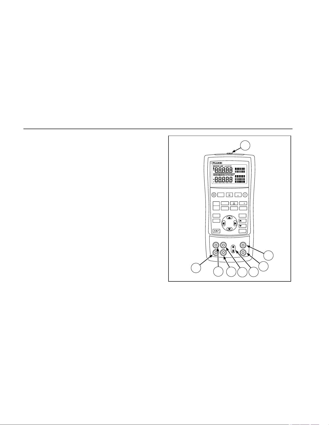
Figure 2 shows the calibrator input and output terminals.
Table 3 explains their use.
V mA
LOO P
V mA
TC RTD
°
C
°
F
Hz
100%
25%
25%
RECALL
ZERO
MEAS
SOURCE
STORE
SETUP
0%
MULTIFUNCTION CALIBRATOR
725
8
7
6
5
4
3
2
1
sh05f.eps
Figure 2. Input/Output Terminals and Connectors
1.888.610.7664 sales@GlobalTestSupply.com
Fluke-Direct.com
Loading ...
Loading ...
Loading ...