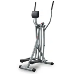
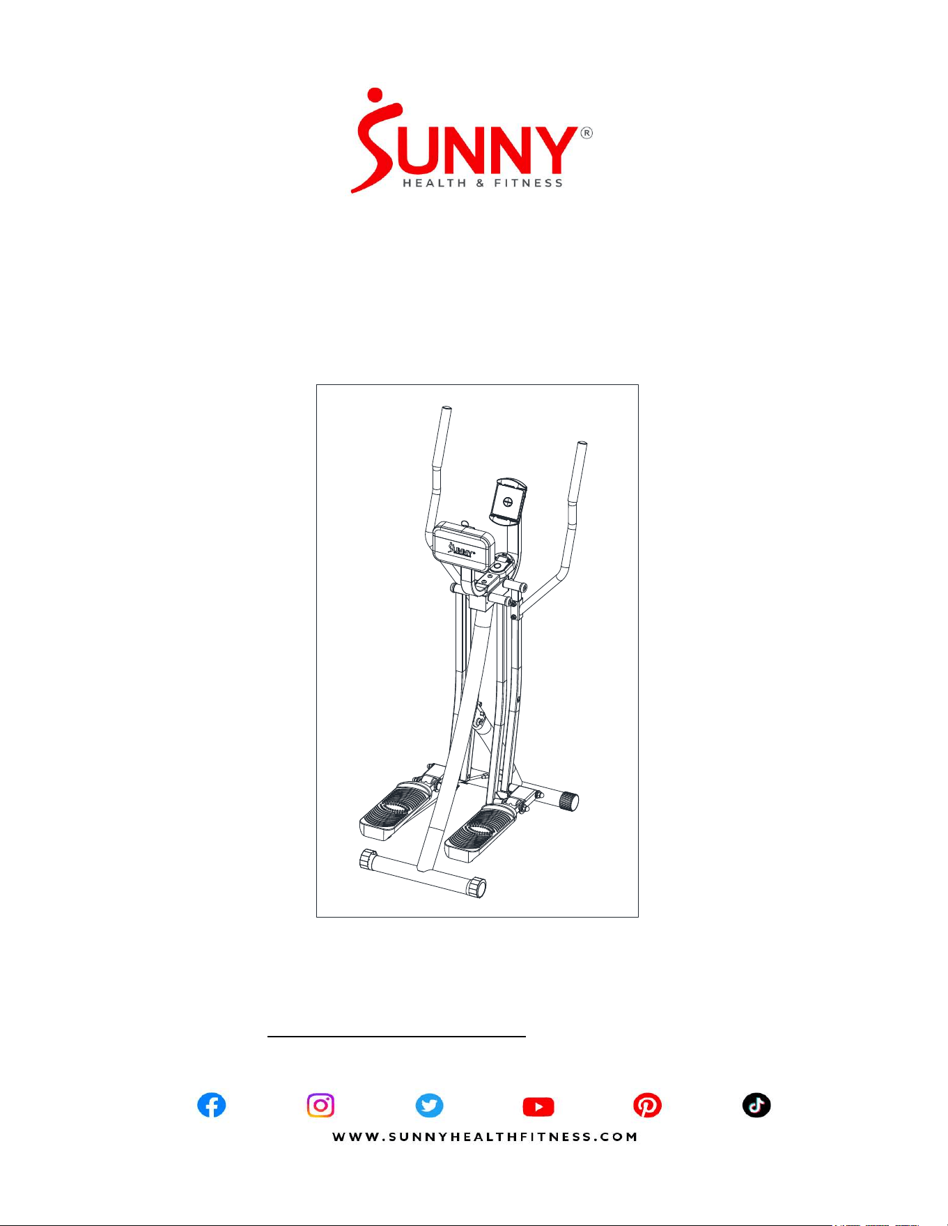
AIR WALK TRAINER PRO
SF-E902S
USER MANUAL
IMPORTANT! Please retain owner’s manual for maintenance and adjustment instructions.
Your satisfaction is very important to us, PLEASE DO NOT RETURN UNTIL YOU HAVE
CONTACTED US: support@sunnyhealthfitness.com or 1- 877 - 90SUNNY (877-907-
8669).

1
IMPORTANT SAFETY INFORMATION
We thank you for choosing our product. To ensure your safety and health, please use this
equipment correctly. It is important to read this entire manual before assembling and using
the equipment. Safe and effective use can only be achieved if the equipment is assembled,
maintained, and used properly. It is your responsibility to ensure that all users of the
equipment are informed of all warnings and precautions.
1. Before starting any exercise program, you should consult your physician to determine if
you have any medical or physical conditions that could put your health and safety at risk
or prevent you from using the equipment properly. Your physician’s advice is essential if
you are taking medication that affects your heart rate, blood pressure, or cholesterol
level.
2. Be aware of your body’s signals. Incorrect or excessive exercise can damage your
health. Stop exercising if you experience any of the following symptoms: pain, tightness
in your chest, irregular heartbeat, shortness of breath, lightheartedness, dizziness, or
feelings of nausea. If you do experience any of these conditions, you should consult
your physician before continuing with your exercise program.
3. Keep children and pets away from the equipment. The equipment is designed for adult
use only.
4. Use the equipment on a solid, flat level surface with a protective cover for your floor or
carpet. To ensure safety, the equipment should have at least 2 feet (60 CM) of free
space all around it.
5. Ensure that all nuts and bolts are securely tightened before using the equipment. The
safety of the equipment can only be maintained if it is regularly examined for damage
and/ or wear and tear.
6. Always use the equipment as indicated. If you find any defective components while
assembling or checking the equipment, or if you hear any unusual noises coming from
the equipment during exercise, discontinue use of the equipment immediately and do
not use until the problem has been rectified.
7. Wear suitable clothing while using the equipment. Avoid wearing loose clothing that
may become entangled in the equipment.
8. Do not place fingers or objects into the moving parts of the equipment.
9. The maximum weight capacity of this unit is 220 lbs (100 kgs).
10. The equipment is not suitable for therapeutic use.
11. To avoid bodily injury and/or damage to the product or property, proper lifting and
moving are required.
12. Your product is intended for use in cool, dry conditions. You should avoid storage in
extreme cold, hot, or damp areas as this may lead to corrosion and other related
problems.
13. This equipment is designed for indoor and home use only; it is not intended for
commercial use!
2
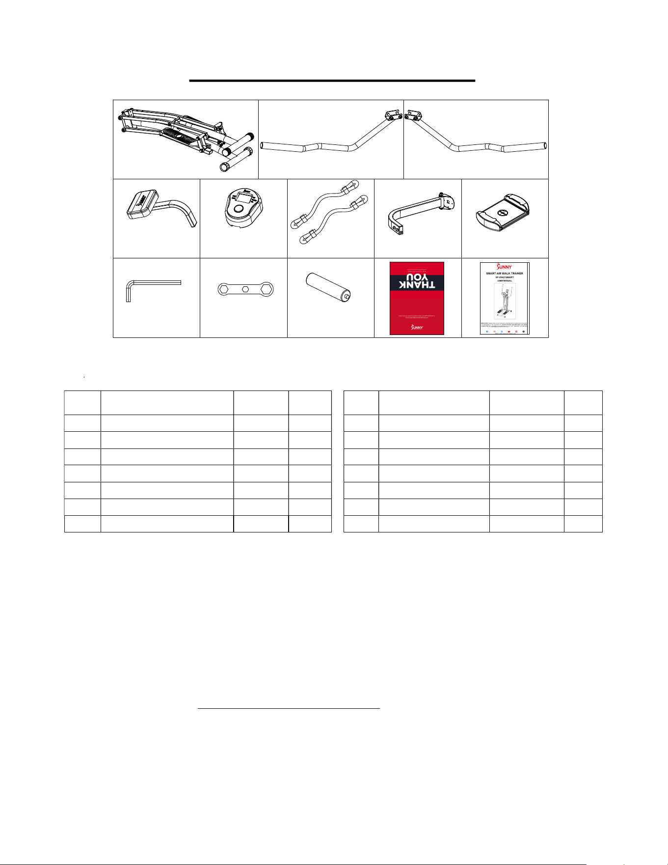
PRE-ASSEMBLY CHECKLIST
1
3L
3R
11
17-1
50-2
51
54
A
B
C
D:\WXWork\168885599164 7028\Cache\Image\2024-07\企业微信截图_17205790952926.png
No. Description Spec. Qty.
No. Description Spec. Qty.
1 Main Frame 1 54 Device Holder 1
3L Left Handlebar 1 A
Allen Key S6 1
3R Right Handlebar 1 B
Wrench S10-13-17 1
11 Support Tube 1 C
Battery AA 2
17-1 Meter JJD2601 1 D
Thank You Card 1
50-2 Resistance Band 2 E
User Manual 1
51 Device Holder Support Tube 1
Ordering Replacement Parts (U.S. and Canadian Customers only)
Please provide the following information in order for us to accurately identify the part(s)
needed:
The model number (found on cover of manual)
The product name (found on cover of manual)
The part number found on the “EXPLODED DIAGRAM” (page 15) and “PARTS LIST”
(page 14).
Please contact us at [email protected] or 1-877-90SUNNY (877-907-
8669).
3
ASSEMBLY INSTRUCTIONS
We value your experience using Sunny Health and Fitness products. For assistance with parts
or troubleshooting, please contact us at su[email protected]om or 1-877-90SUNNY
(877-907-8669).
1
26
45
1
43
43
36L
36R
1
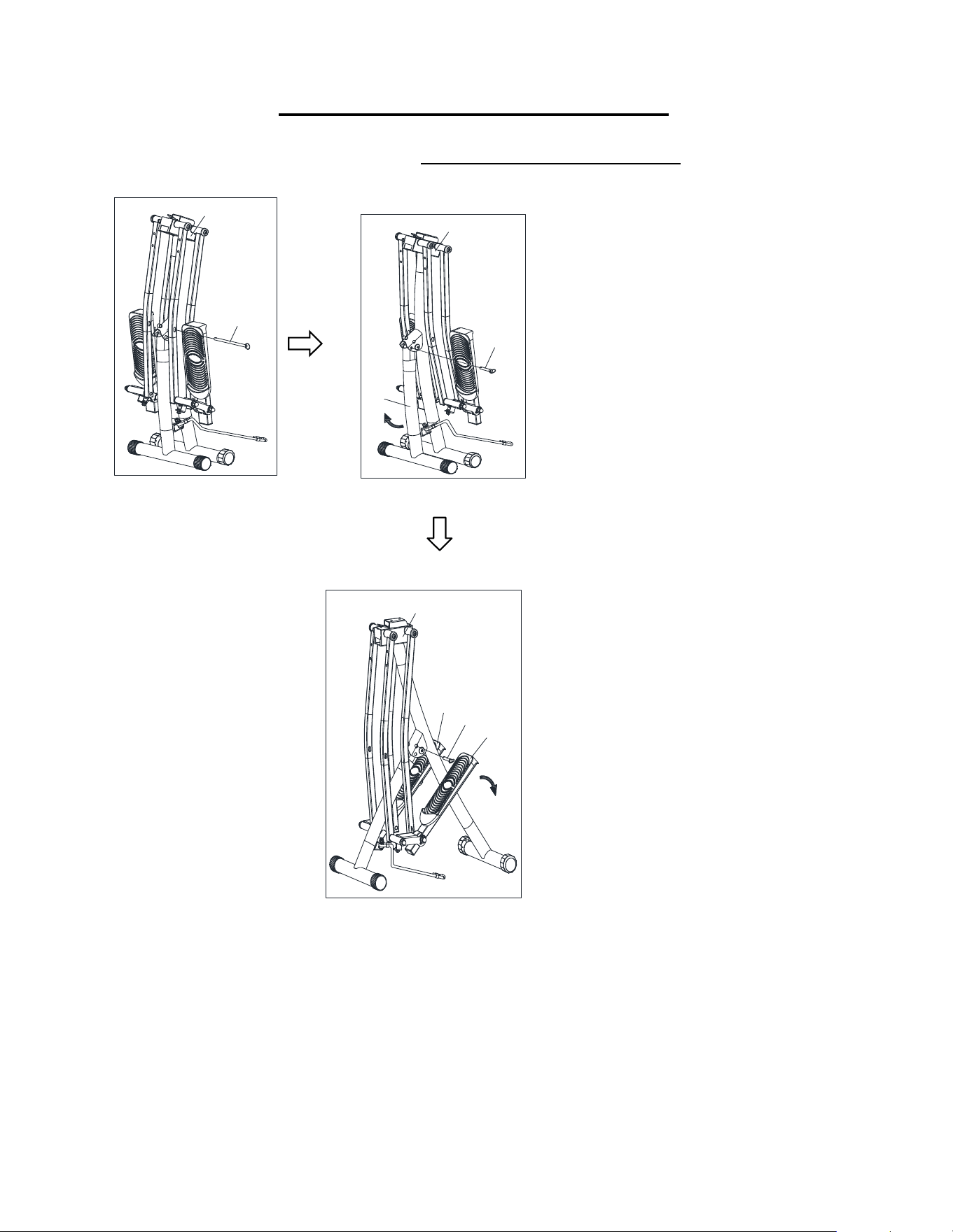
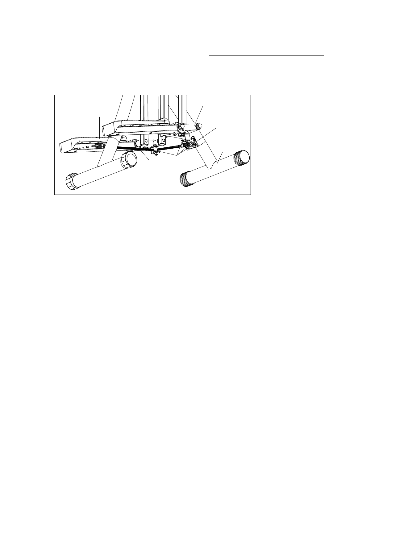
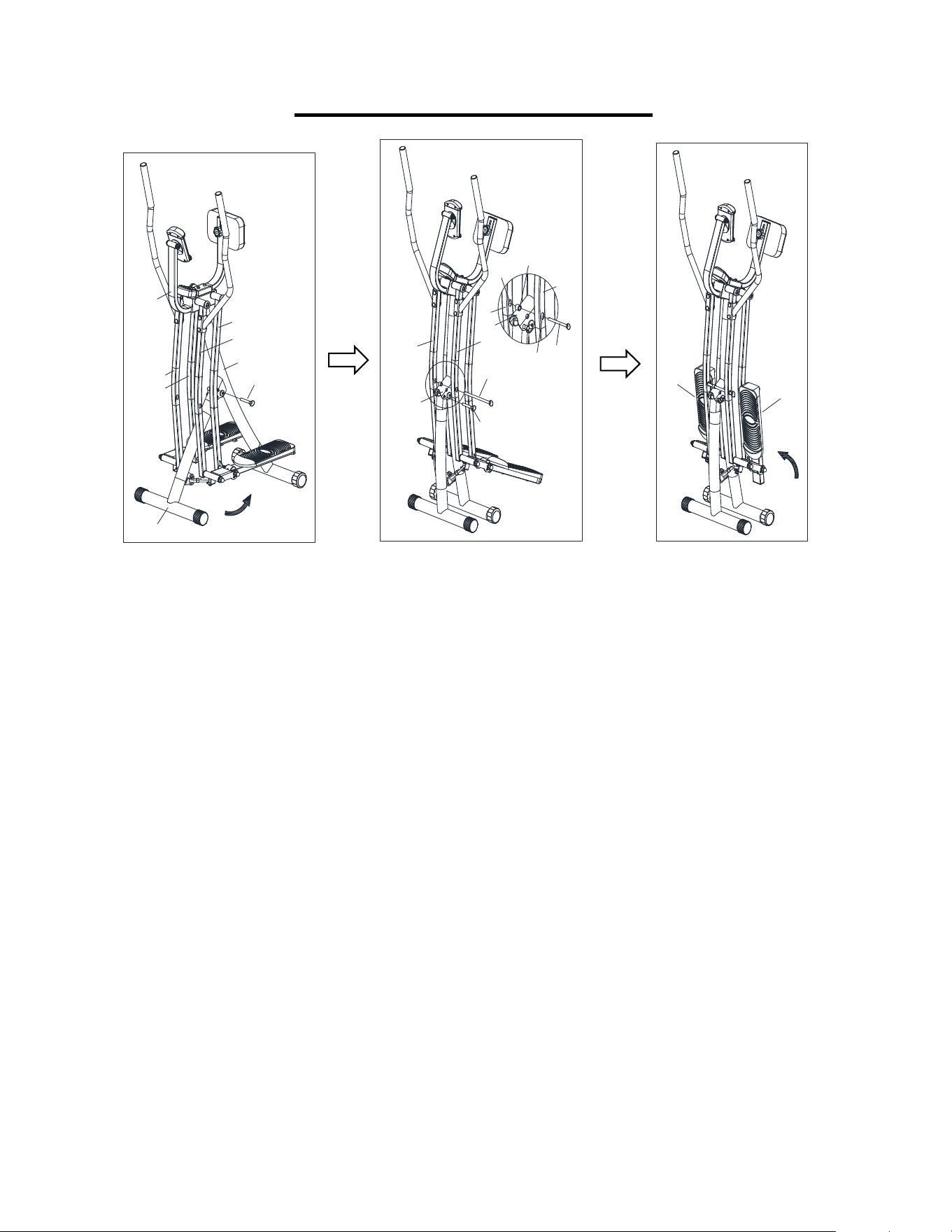
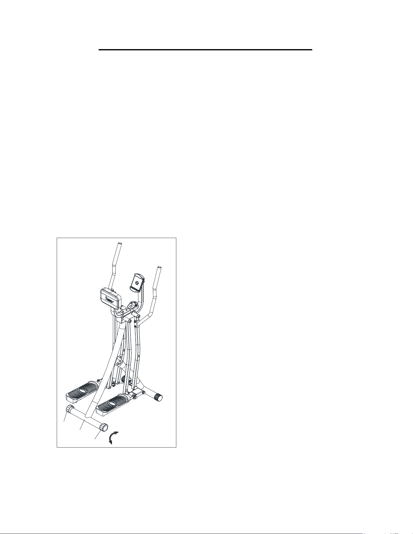
STEP 1:
Unfolding the Air Walker
Trainer
Pull out the large
Ball Pin (No. 26)
,
located half-way through the swing
bars, to unlock the swing bars.
Pull out the
Ball Pin (No. 43)
located
in the hinge where the two support
tubes meet. This will unlock the
Connecting tube (No. 45)
from the
Main Frame (No. 1)
.
Push the
Connecting Tube
(No. 45)
away from the
Main Frame (No. 1)
or
direction indicated by the arrow.
Reinsert the
Ball Pin (No. 43)
into the
aligned holes on the hinge to secure
the
Main Frame (No. 1)
.
NOTE: When Connecting Tube (No.
45) moved, the Right Front Tube (No.
23), Right Rear Tube (No. 24), Left
Rear Tube (No. 27) and Left Front
Tube (No. 28) will move as well. Be
careful not to hurt your arms.
Unfold
Left Pedal Tube (No. 36L)
and
Right Pedal Tube (No. 36R)
to
have the machine fully unfolded.
4
We value your experience using Sunny Health and Fitness products. For assistance with
parts or troubleshooting, please contact us at [email protected]m or 1-877-
90SUNNY (877-907-8669).
#16 M 8*1 6 2P C S
26
11
16
1
#A S 6 1PC
6
6
5
4
5
4
28
23
3L
3R
#B S10-13-17 1PC
#4 M8 4PCS
#5 φ8.2*φ16*1.5 4PCS
#6 M8*42 4PCS
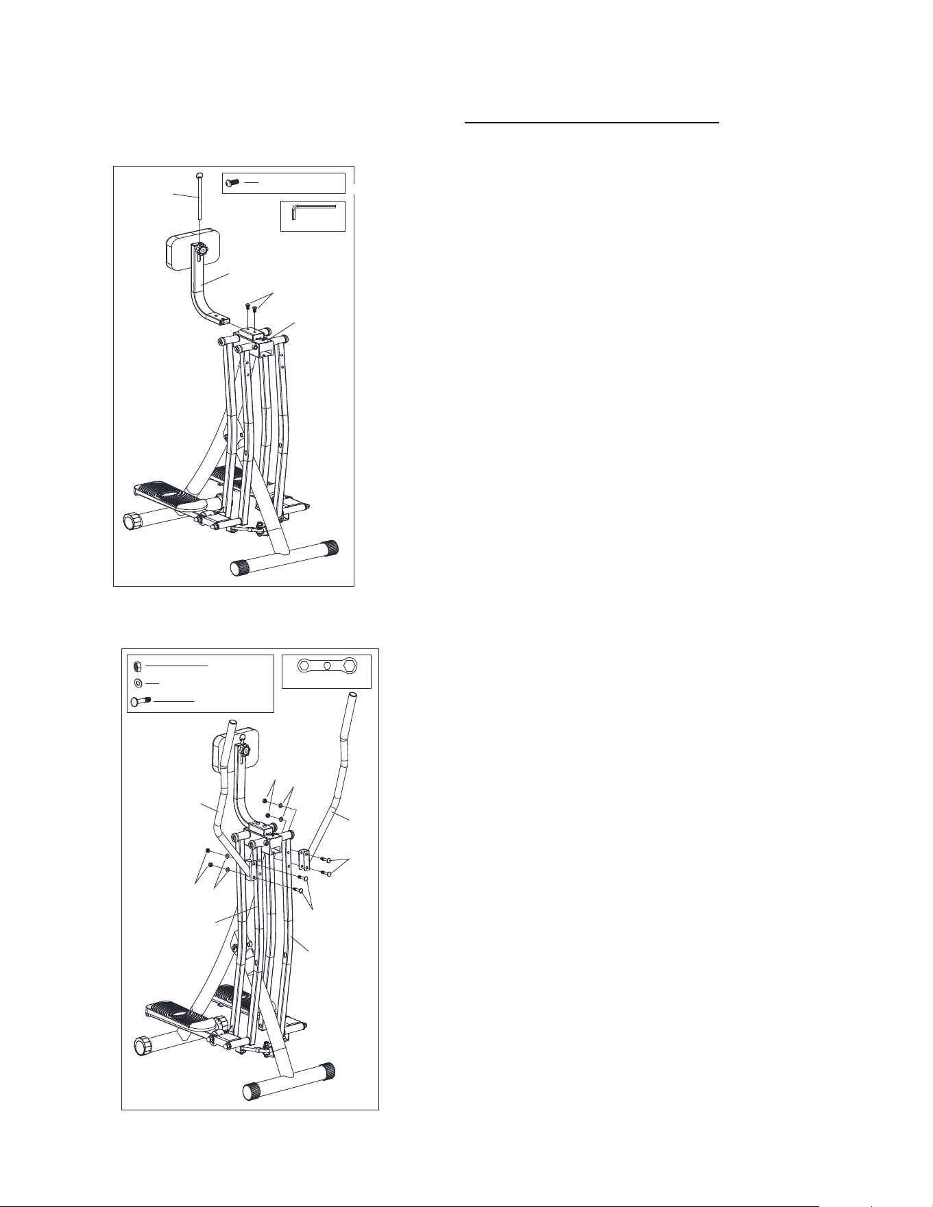
STEP 2:
Attaching the Support Tube
Remove 2 Allen Screws (No. 16) From Support
Tube (No. 11).
Insert the Support Tube (No. 11) into the slot located
at the top of the Main Frame (No. 1).
Align the holes on the Support Tube (No. 11) with
the holes on the slot. Insert two Allen Screws (No.
16) into each hole and use the Allen Key (No. A) to
secure them.
Insert the Ball Pin (No. 26) into the top hole of the
Support Tube (No. 11) for safe keeping.
STEP 3:
Assembling the Handlebars
Remove
2
Bolts (No. 6)
,
2
Washers (No. 5)
and
2
Nuts (No. 4)
from
Left Handlebar (No. 3L)
.
Make sure the square holes on each handlebar
are facing outward, as shown on the left. Insert 2
Bolts (No. 6)
making sure the square part of the
bolts lock into the square holes on the
Left
Handlebar (No. 3L)
.
Place a
Washer (No. 5)
and a
Nut (No. 4)
on each
Bolt (No. 6)
and use
Wrench (No. B)
to secure the
Left Handlebar
(No. 3L)
onto the
Left Front Tube (No. 28)
.
Use the same steps to secure the
Right
Handlebar (No. 3R)
onto the
Right Front Tube
(No. 23)
.
5
We value your experience using Sunny Health and Fitness products. For assistance with
parts or troubleshooting, please contact us at [email protected]m or 1-877-
90SUNNY (877-907-8669).
#A S6 1PC
#58 M8*16 2PCS
51
54
57
56
#56 φ6.4*φ18*1.2 1PC
#57 M6 1PC
F
G
F
G
1
51
58
1
17-1
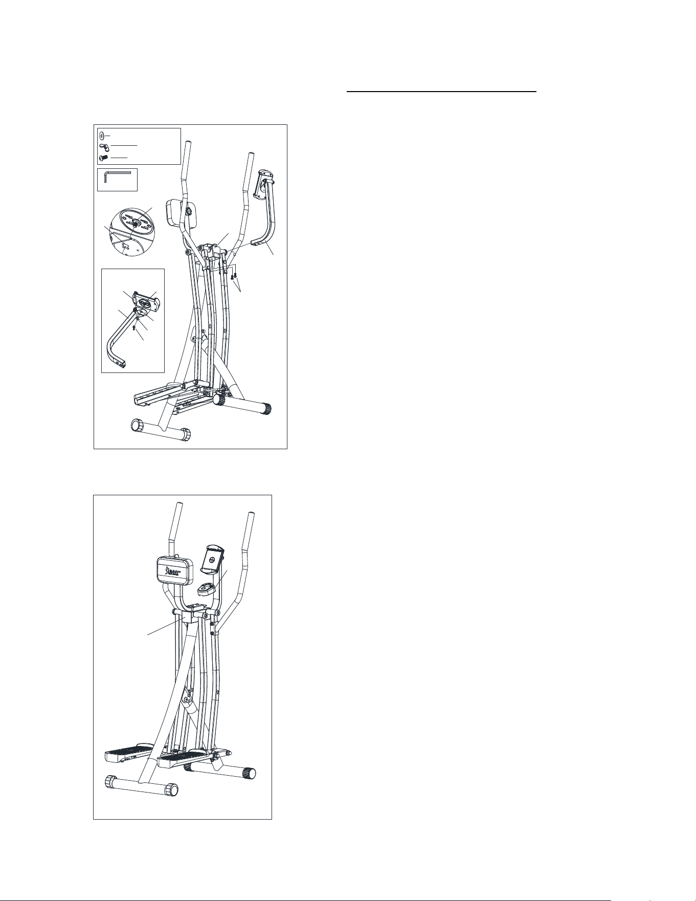
STEP 4:
Assembling Device Holder
Unscrew the Nut (No. 57) and Flat Washer (No. 56)
on the Device Holder (No. 54).
Attach the Device Holder (No. 54) to the Device
Holder Support Tube (No. 51) by using the same
Nut (No. 57) and Flat Washer (No. 56).
NOTE: The gap (F) of the Device Holder (No. 54)
and the gap (G) of the Device Holder Support
Tube (No. 51) should be aligned.
Remove 2 Bolts (No. 58) from Device Holder
Support Tube (No. 51).
Insert the Device Holder Support Tube (No. 51)
into the Main Frame (No. 1). Then secure it with 2
Bolts (No. 58) using an Allen Key (No. A).
STEP 5:
Attaching the Meter
Slide the
Meter (No. 17-1)
onto the bracket
located on the
Main Frame (No. 1)
.
6
We value your experience using Sunny Health and Fitness products. For assistance with
parts or troubleshooting, please contact us at [email protected]m or 1-877-
90SUNNY (877-907-8669).
36L
49
50-2
50
45
36R
STEP 6:
Attaching the Resistance Band
Pass the Resistance Band (No. 50-
2) through the slot between the
Wheel (No. 49) and the sheet metal
under the Left Pedal Tube (No.
36L), as shown by the arrow. (Show
as the arrow). Continue connecting
the end of the Resistance Band
(No. 50-2) to the hook below the Left
Pedal Tube (No. 36L), as shown by
the arrow.
Repeat this procedure on the right
side.
NOTE: There are 3 hooks under the
Left Pedal Tube (No. 36L) and
Right Pedal Tube (No. 36R). The
hooks can be used to adjust the
resistance according to your own
needs.
50
-
2
7
FOLDING INSTRUCTIONS
43
1
45
23
24
28
27
51
43
1
26
23
28
1
27
23
26
H1
H2
H3
36R
36L
1. Take out the Ball Pin (No. 43) from the Main Frame (No. 1). Hold the Device Holder
Support Tube (No. 51), then move the Connecting Tube (No. 45) toward the Main
Frame (No. 1) as pictured.
NOTE: When Connecting Tube (No. 45) moved, the Right Front Tube (No. 23), Right
Rear Tube (No. 24), Left Rear Tube (No. 27) and Left Front Tube (No. 28) will move
as well. Be careful not to hurt your arms.
2. Insert Ball Pin (No. 43) into the folding hole of the Main Frame (No. 1). Insert the Ball
Pin (No. 26) into the hole H1 of the Left Rear Tube (No. 27), the hole H2 of the Main
Frame (No. 1) and the hole H3 of the Right Front Tube (No. 23) accordingly.
3. Fold the Left Pedal Tube (No. 36L) and the Right Pedal Tube (No. 36R) in the
direction indicated by the arrows.
NOTE: After folding, it is recommended that the product be placed against the wall to
prevent falling.
8
REPLACE THE RESISTANCE BAND
36L
49
50-2
45
36L
49
50-2
45
48
5
4
36L
49
50-2
45
48
5
4
36L
49
50-2
45
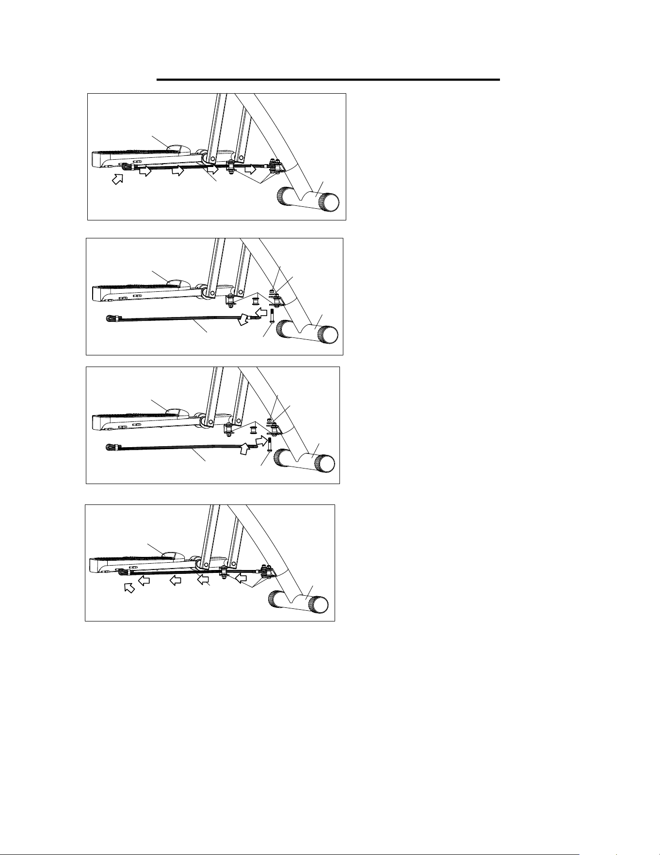
STEP 2:
Remove
Bolt (No. 48)
,
Washer (No. 5)
and
Nut (No. 4)
from
Connecting Tube
(No. 45)
by using
Allen Key (No. A)
and
Wrench (No. B)
. Take out
Wheel (No. 49)
and
Resistance Band (No. 50-2)
,
as
shown by the arrow.
STEP 1:
Remove the end of the
Resistance Band
(No. 50-2)
from the
Left Pedal Tube (No.
36L)
. Next, pass the
Resistance Band
(No. 50-2)
through the slot between the
sheet metal below the
Wheel (No. 49)
and
the
Left Pedal Tube (No. 36L),
as shown
by the arrow.
STEP 3:
Take out the new
Resistance Band (No. 50-
2)
from the manual bag. Attach the
Wheel
(No. 49)
and new
Resistance Band (No. 50-
2)
back to the
Connecting Tube (No. 45)
.
Use the
Allen Key (No. A)
and
Wrench (No.
B)
to tighten
Bolt (No. 48)
,
Washer (No. 5)
and
Nut (No. 4)
back to the
Connecting
Tube (No. 45),
as shown by the arrow.
STEP 4:
Pass the new
Resistance Band (No. 50-2)
through the slot between the
Wheel (No. 49)
and the sheet metal under the
Left Pedal
Tube (No. 36L)
as shown by the arrow. Then,
connect the end of the new
Resistance Band
(No. 50-2)
to the hook below the
Left Pedal
Tube (No. 36L),
as shown by the arrow.
Repeat this procedure (Step 1- Step 4) on the
right side.
NOTE: There are 3 hooks under the Left Pedal
Tube (No. 36L) and Right Pedal Tube (No.
36R). The hooks can be used to adjust the
resistance according to your own needs.
9
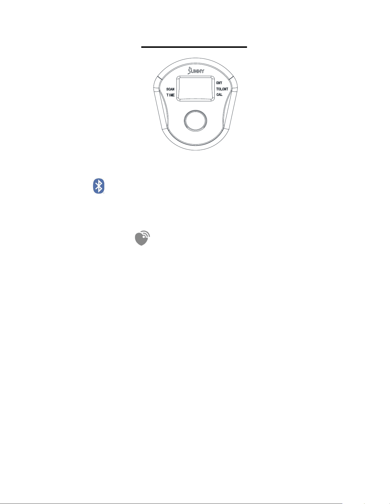
EXERCISE METER
BLUETOOTH :
1. The Bluetooth icon will flash when the meter is on or wakes from sleep mode. If no
Bluetooth connection is established within 3 minutes, the Bluetooth icon will turn off.
2. The Bluetooth icon will stay on when it is connected.
WIRELESS HEART RATE
:
1. The wireless heart rate icon will flash when the meter is on. If the heart rate monitor is
not connected within 1 minute, the wireless heart rate icon will turn off.
2. After exercise resumes, the wireless heart rate icon will flash. If the heart rate monitor is
not connected within 1 minute, the wireless heart rate icon will turn off.
3. When the meter wakes from sleep mode, the wireless heart rate icon will flash. If the
heart rate monitor is not connected within 1 minute, the wireless heart rate icon will turn
off.
4. The wireless heart rate icon will flash when the MODE key is pressed. If the heart rate
monitor is not connected within 1 minute, the wireless heart rate icon will turn off.
5. The wireless heart rate icon will stay on when the heart rate monitor is connected.
NOTE: The heart rate monitor is not included. Wireless heart rate function works with
SunnyFit Heart Rate Monitor HR200. HR200 can only connect to the computer when the
wireless heart rate icon is flashing.

10
KEY FUNCTION:
MODE/SELECT: To select the function you want. Hold the key for 3 seconds to reset
values CNT TIME CAL except TOT when the Bluetooth is not connected.
Press and hold the MODE key for 6 seconds to disconnect from both the SunnyFit APP
and the heart rate monitor; then, the meter will enter sleep mode.
AUTO ON/OFF: The monitor will be turned on automatically when exercise starts or the
key pressed. The meter will shut off automatically and disconnect the heart rate monitor if
there is no activity for 4 minutes.
FUNCTIONS:
TIME: Display the total time since the exercise started
CNT: Display the steps count while exercising.
CAL: Display the total calories burned while exercising.
TOT CNT: Display the total steps of all your sessions. The Total Count will be reset once
you replace/disconnect the battery.
SCAN: Press the button to select "scan". This function will automatically scan through
TIME, CALORIES, TOTAL COUNT and P (PULSE) displayed on the bottom of the monitor.
P (PULSE): Display current heart rate value. The data comes from the matching Bluetooth
heart rate monitor.
SPECIFICATIONS:
CNT------------------------------------------------- 0—9999 TIMES
TIME------------------------------------------------ 00:00—99:59 MIN: SEC
CALORIES---------------------------------------- 0—9999 KCAL
TOT.CNT------------------------------------------ 0—9999 TIMES
P (PULSE)---------------------------------------- 40-240 BPM
NOTE: Please replace the battery when the meter does not display properly.
TECHNICAL DATA
Connectivity: Bluetooth LE
Frequency Range: 2400~2483.5Mhz
Transmitting Power: 0dBm
11
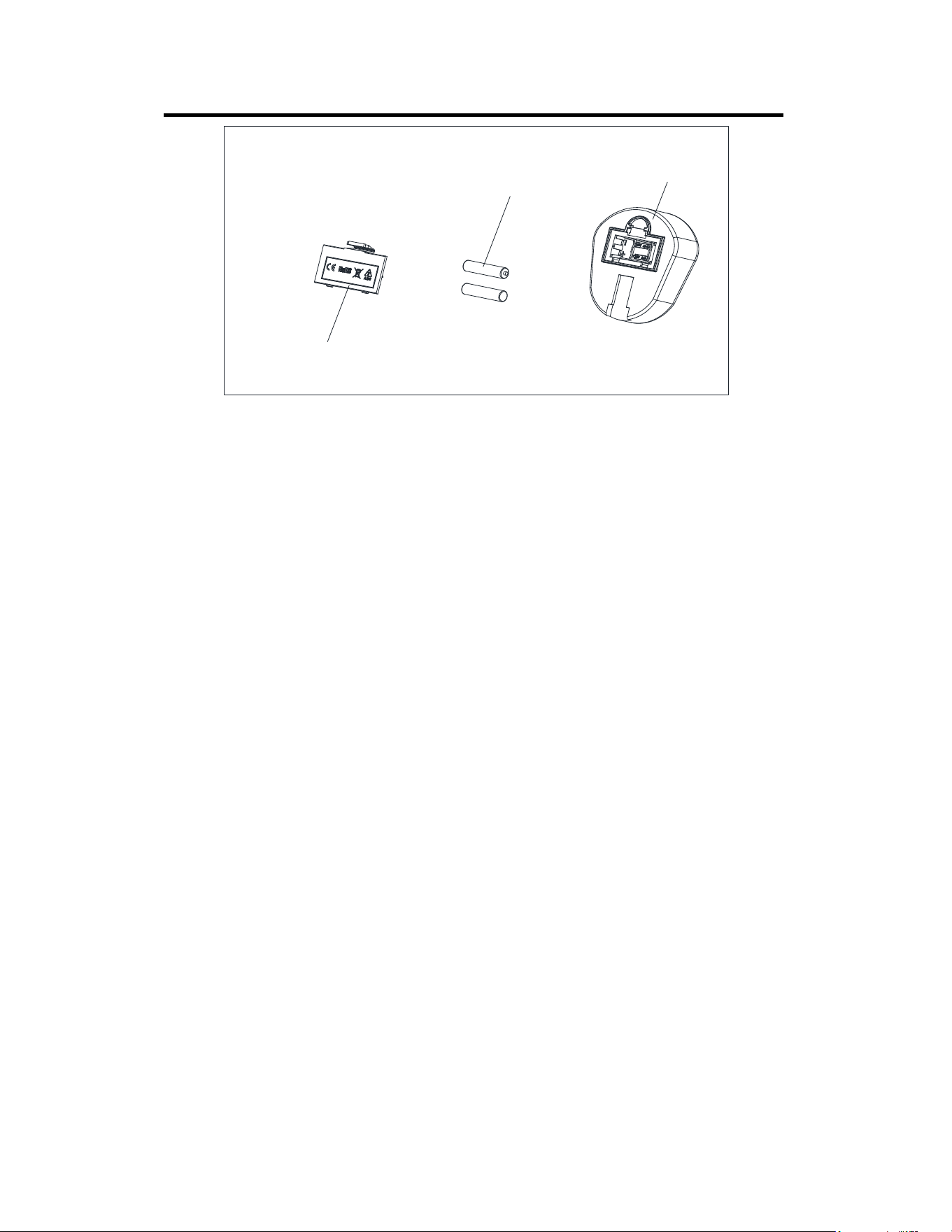
BATTERY INSTALLATION & REPLACEMENT
BATTERY INSTALLATION:
1. Press the buckle of the battery cover on the back of the Meter (No. 17-1) to remove
battery cover.
2. Install 2 AA batteries into the battery case on the back of the Meter (No. 17-1). Pay
attention to the battery + and – ends before installing.
3. Press the buckle of the battery cover, then put the battery cover back to the back of the
Meter (No. 17-1).
The installation is complete!
BATTERY REPLACEMENT:
1. Press the buckle of the battery cover on the back of the Meter (No. 17-1), to remove the
battery cover.
2. Remove the 2 old AA batteries in the battery case and install 2 new AA batteries into the
battery case on the back of the Meter (No. 17-1). Pay attention to the battery + and – ends
before installing.
3. Press the buckle of the battery cover, then put the battery cover back to the back of the
Meter (No. 17-1).
The replacement is complete!
NOTE: Always change both batteries at the same time. Do not mix battery types and do
not mix old and new batteries. Dispose batteries according to your state and regional
guidelines.
Batteries
Battery Cover
17-1
12
USING THE AIR WALKER TRAINER
PLACING YOUR FEET ON THE AIR WALKER TRAINER
Stand behind the Air Walker Trainer with each hand holding one of the handlebars. Make
sure to push and pull each handlebar prior to placing your feet on the foot pedals, to feel
the tension and motion of the machine. Steadily hold the right handlebar as you
place your right foot on the right pedal. Continue to steadily hold each of the handlebars as
you balance on your right foot to lift your left foot and place it on the left pedal.
USING THE AIR WALKER TRAINER
For optimal movement you will need to have a steady push and pull motion. As you push
one arm, you will need to pull the other arm, in tandem, to create a steady walking motion
on the machine. Make sure you are balanced and use smooth, controlled movements.
BALANCE ADJUSTMENT
Before using, check the balance of the product to ensure it is safe for use. Put the product
on a flat, even surface. If the product is slightly uneven, rotate the Adjustable Caps (No.
46) on the Main Frame (No. 1) to compensate for the uneven ground.
46
1
46
13
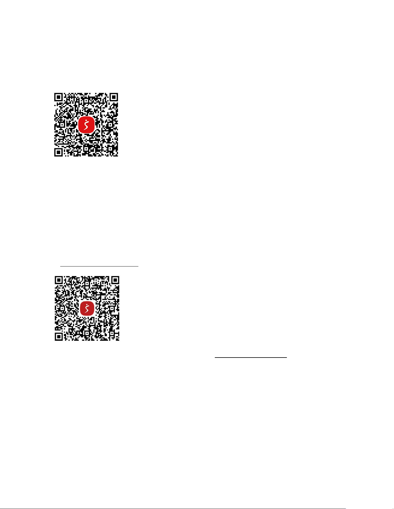
APP CONNECTION:
Connect Smart Equipment to SunnyFit App:
1. Scan to download SunnyFit from the app store:
2. Ensure that the Bluetooth function is turned on from your mobile device.
3. If this is your first time using the SunnyFit app, follow the in-app instructions to register
for your free SunnyFit account and log in.
4. Begin any workout activity that matches your smart equipment, then follow the onscreen
prompts to search for and connect to your smart equipment.
5. When connected, your stats and records will be displayed at the end of your
course/session, and recorded in your account profile!
Troubleshooting:
If you are having trouble connecting your smart equipment, visit
www.sunnyfit.com/guide or scan the QR code below:
If you require additional support, please contact [email protected].

14
PARTS LIST
No. Description Spec. Qty.
No. Description Spec. Qty.
1 Main Frame 1 33R Right Pedal Connector 1
2 Sponge φ29*φ23*200 2 34 Bearing Sleeve 4
3L Left Handlebar 1 35 Screw ST4.8*20 4
3R Right Handlebar 1 36L Left Pedal Tube 1
4 Nut M8 9 36R Right Pedal Tube 1
5 Washer φ8.2*φ16*1.5 9 37 Plug F25*50*1.5 2
6 Bolt M8*42 4 38 Stopper 4
7 Screw M8*20 4 39 Connecting Sleeve 2
8 Bolt Cap 4 40 Plug F25*25*2.0 4
9 Washer φ8.2*φ25*1.5 4 41 Front Cap φ50 2
10 Bearing Sleeve 8 42 Bolt φ12*32.5, M8 1
11 Support Tube 1 43 Ball Pin φ10*66.5 1
12 Chest Pad 1 44 Bolt φ12*22.5, M8 1
13 Plug F20*40*1.5 3 45 Connecting Tube 1
14 Knob M8*30 1 46 Adjustable Cap φ50 2
15 Screw M8*15 1 47 EVA Pad 1
16 Allen Screw M8*16 2 48 Bolt M8*40 4
17-1 Meter JJD2601 1 49 Wheel φ21*φ8.1*22 4
18 Plug F60*60*2.0 1 50-2 Resistance Band φ8*360 4
19 Magnet Bracket 1 51
Device Holder Support
Tube
1
20 Screw M3 1 52 Sleeve φ22 2
21 Magnet 1 53 Bolt M8*75 1
22 Cap 4 54 Device Holder 1
23 Right Front Tube 1 55
Device Holder Fix
Plate
1
24 Right Rear Tube 1 56 Flat Washer φ6.4*φ18*1.2 1
25 Plug φ25*1.5 2 57
Nut
M6 1
26 Ball Pin φ10*180 1 58 Bolt M8*16 2
27 Left Rear Tube 1 59 Bolt M5*12 1
28 Left Front Tube 1 60 Rubber Cushion 20*40*2.0 2
29 Pedal 2 A Allen Key S6 1
30 Nut M10 4 B Wrench S10-13-17 1
31 Washer φ10.5*φ26*2.0 4 C Battery AA 2
32 Bearing Sleeve 4 D Thank You Card 1
33L
Left Pedal
Connector
1 E User Manual 1
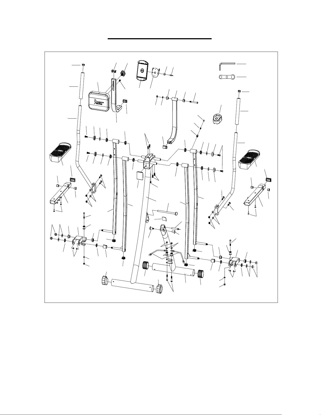
15
EXPLODED DIAGRAM
25
2
3R
25
2
3L
4
5
6
6
4
5
6
7
8
9
10
9
10
8
10
10
10
7
8
9
10
10
10
9
8
7
11
12
13
13
13
14
15
16
17
18
19
20
21
22
22
22
22
23
24
1
26
27
28
29
29
30
30
31
31
32
32
32
32
33L
33R
34
34
34
34
35
35
36L
36R
37
37
38
38
39
39
40
40
40
40
41
41
42
43
44
45
46
46
48
49
5
48
49
5
4
5
4
49
48
51
52
52
53
5
4
4
54
55
56
57
A
B
59
58
47
50-2
Version 1.
0