5608/5609
Platinum Resistance Thermometer
User’ s Guide
Rev. 712601
Hart Scientific
1.888.610.7664 sales@GlobalTestSupply.com
Fluke-Direct.com

Rev. 712601
Limited Warranty & Limitation of Liability
Each product from Fluke Corporation,
Hart Scientific Division ("Hart") is warranted to be free from de
-
fects in material and workmanship under normal use and service. The warranty period is one year(s)
for the Platinum Resistance Thermometer. The warranty period begins on the date of the shipment.
Parts, product repairs, and services are warranted for 90 days. The warranty extends only to the
original buyer or end-user customer of a Hart authorized reseller, and does not apply to fuses, dispos
-
able batteries or to any other product, which in Hart's opinion, has been misused, altered, neglected,
or damaged by accident or abnormal conditions of operation or handling. Hart warrants that software
will operate substantially in accordance with its functional specifications for 90 days and that it has
been properly recorded on non-defective media. Hart does not warrant that software will be error
free or operate without interruption. Hart does not warrant calibrations on the Platinum Resistance
Thermometer.
Hart authorized resellers shall extend this warranty on new and unused products to end-user cus
-
tomers only but have no authority to extend a greater or different warranty on behalf of Hart. War
-
ranty support is available if product is purchased through a Hart authorized sales outlet or Buyer has
paid the applicable international price. Hart reserves the right to invoice Buyer for importation costs
of repairs/replacement parts when product purchased in one country is submitted for repair in an
-
other country.
Hart's warranty obligation is limited, at Hart's option, to refund of the purchase price, free of charge
repair, or replacement of a defective product which is returned to a Hart authorized service center
within the warranty period.
To obtain warranty service, contact your nearest Hart authorized service center or send the product,
with a description of the difficulty, postage, and insurance prepaid (FOB Destination), to the nearest
Hart authorized service center. Hart assumes no risk for damage in transit. Following warranty repair,
the product will be returned to Buyer, transportation prepaid (FOB Destination). If Hart determines
that the failure was caused by misuse, alteration, accident or abnormal condition or operation or
handling, Hart will provide an estimate or repair costs and obtain authorization before commencing
the work. Following repair, the product will be returned to the Buyer transportation prepaid and the
Buyer will be billed for the repair and return transportation charges (FOB Shipping Point).
THIS WARRANTYISBUYER'S SOLEANDEXCLUSIVEREMEDY ANDISINLIEUOFALLOTHERWAR
-
RANTIES, EXPRESS OR IMPLIED, INCLUDING BUT NOT LIMITED TO ANY IMPLIED WARRANTY OF
MERCHANTABILITY OR FITNESS FOR A PARTICULAR PURPOSE. HART SHALL NOT BE LIABLE FOR
ANY SPECIAL, INDIRECT, INCIDENTAL. OR CONSEQUENTIAL DAMAGES OR LOSSES, INCLUDING LOSS
OF DATA, WHETHER ARISING FROM BREACH OF WARRANTY OR BASED ON CONTRACT, TORT, RELI
-
ANCE OR ANY OTHER THEORY.
Since some countries or states do not allow limitation of the term of an implied warranty, or exclu
-
sion or limitation of incidental or consequential damages, the limitations and exclusions of this war
-
ranty may not apply to every buyer. If any provision of this Warranty is held invalid or unenforceable
by a court of competent jurisdiction, such holding will not affect the validity or enforceability of any
other provision.
Subject to change without notice. • Copyright © 2005 • Printed in USA
1.888.610.7664 sales@GlobalTestSupply.com
Fluke-Direct.com

Table of Contents
1 Before You Start . . . . . . . . . . . . . . . . . . . . . . 1
1.1 Symbols Used . . . . . . . . . . . . . . . . . . . . . . . . . 1
1.2 Safety Information . . . . . . . . . . . . . . . . . . . . . . . 2
1.2.1 Warnings . . . . . . . . . . . . . . . . . . . . . . . . . . . . . . . . 2
1.2.2 Cautions . . . . . . . . . . . . . . . . . . . . . . . . . . . . . . . . . 2
2 Introduction . . . . . . . . . . . . . . . . . . . . . . . . 5
2.1 General . . . . . . . . . . . . . . . . . . . . . . . . . . . . 5
2.2 Application. . . . . . . . . . . . . . . . . . . . . . . . . . . 5
2.3 Calibration . . . . . . . . . . . . . . . . . . . . . . . . . . . 5
2.4 Recalibration. . . . . . . . . . . . . . . . . . . . . . . . . . 5
3 Specifications . . . . . . . . . . . . . . . . . . . . . . . 7
3.1 Specifications . . . . . . . . . . . . . . . . . . . . . . . . . 7
3.2 Electrical Circuit . . . . . . . . . . . . . . . . . . . . . . . . 8
4 Installation . . . . . . . . . . . . . . . . . . . . . . . . 9
4.1 Environmental Issues . . . . . . . . . . . . . . . . . . . . . 9
4.2 Mounting. . . . . . . . . . . . . . . . . . . . . . . . . . . . 9
4.3 Lead Wire Identification . . . . . . . . . . . . . . . . . . . . 9
5 PRT Care and Handling Guidelines. . . . . . . . . . . . 11
5.1 PRT Care . . . . . . . . . . . . . . . . . . . . . . . . . . . 11
5.2 PRT Handling Guidelines . . . . . . . . . . . . . . . . . . . 11
6 Operation. . . . . . . . . . . . . . . . . . . . . . . . . 13
6.1 General . . . . . . . . . . . . . . . . . . . . . . . . . . . . 13
6.2 Comparison Calibration of Other Instruments. . . . . . . . . 13
6.3 Immersion Requirements . . . . . . . . . . . . . . . . . . . 13
6.4 Thermal EMF . . . . . . . . . . . . . . . . . . . . . . . . . 14
6.5 Transition Junction . . . . . . . . . . . . . . . . . . . . . . 14
7 Accessories. . . . . . . . . . . . . . . . . . . . . . . . 15
7.1 Case Options . . . . . . . . . . . . . . . . . . . . . . . . . 15
i
7.2 PRT Termination . . . . . . . . . . . . . . . . . . . . . . . 15
8 Troubleshooting . . . . . . . . . . . . . . . . . . . . . 17
8.1 Troubleshooting . . . . . . . . . . . . . . . . . . . . . . . 17
1.888.610.7664 sales@GlobalTestSupply.com
Fluke-Direct.com

iii
Figures
Figure 1 PRT Schematic . . . . . . . . . . . . . . . . . . . . . . . . . . . . . . . 9
Figure 2 Probe Termination Examples . . . . . . . . . . . . . . . . . . . . . . . 15
Tables
Table 1 International Electrical Symbols . . . . . . . . . . . . . . . . . . . . . . 1
Table 2 Specifications. . . . . . . . . . . . . . . . . . . . . . . . . . . . . . . . 7
1.888.610.7664 sales@GlobalTestSupply.com
Fluke-Direct.com
1 Before You Start
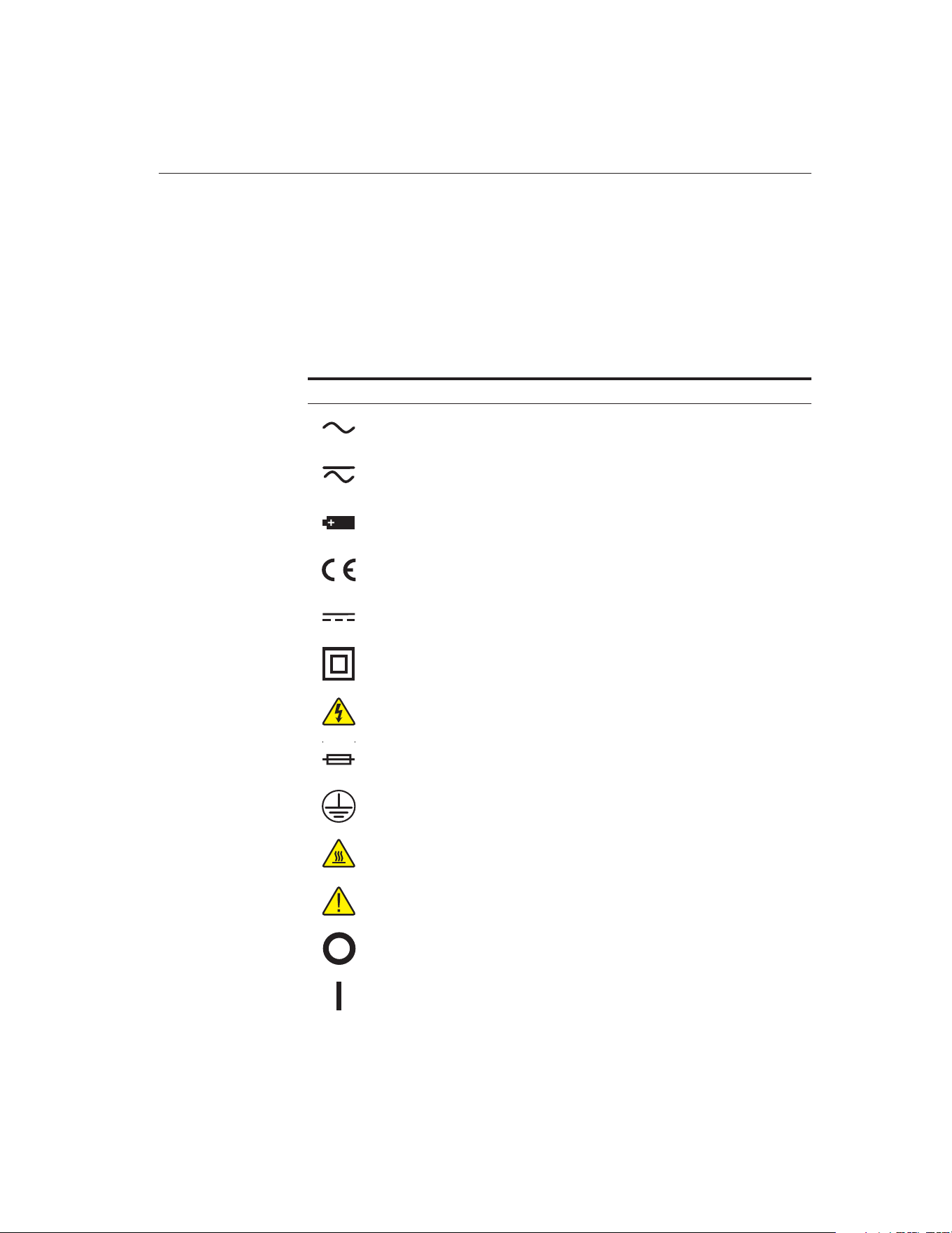
1.1 Symbols Used
Table 1 lists the International Electrical Symbols. Some or all of these sym-
bols may be used on the instrument or in this manual.
Symbol Description
AC (Alternating Current)
AC-DC
Battery
CE Complies with European Union Directives
DC
Double Insulated
Electric Shock
Fuse
PE Ground
Hot Surface (Burn Hazard)
Read the User’s Manual (Important Information)
Off
On
1
1
Before You Start
Table 1 International Electrical Symbols
1.888.610.7664 sales@GlobalTestSupply.com
Fluke-Direct.com
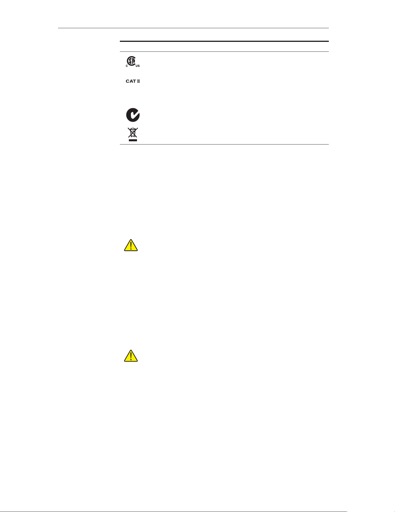
Symbol Description
Canadian Standards Association
OVERVOLTAGE (Installation) CATEGORY II, Pollution Degree 2 per
I E C1010-1 refers to the level of Impulse Withstand Voltage protection
provided. Equipment of OVERVOLTAGE CATEGORY II is energy-con-
suming equipment to be supplied from the fixed installation. Exam-
ples include household, office, and laboratory appliances.
C-TICAustralianEMCMark
The European Waste Electrical and Electronic Equipment (WEEE) Di-
rective (2002/96/EC) mark.
1.2 Safety Information
Use this instrument only as specified in this manual. Otherwise, the protec-
tion provided by the instrument may be impaired.
The following definitions apply to the terms “Warning” and “Caution”.
“Warning” identifies conditions and actions that may pose hazards to the
user.
“Caution” identifies conditions and actions that may damage the instrument
being used.
1.2.1
Warnings
To avoid personal injury, follow these guidelines.
•
DO NOT use this instrument to measure the temperature of any haz-
ardous live component.
•
DO NOT use this unit for any application other than calibration work.
•
DO NOT use this unit in environments other than those listed in the
user’s manual.
•
Use of this instrument at high temperatures for extended periods of
time can cause the handle to become hot.
•
Follow all safety guidelines listed in the user’s manual.
•
Calibration Equipment should only be used by Trained Personnel.
1.2.2
Cautions
To avoid possible damage to the instrument, follow these guidelines.
•
DO NOT remove the label from the handle. This cautions the user con-
cerning the delicate nature of the instrument.
5608/5609
User’s Guide
2
• DO NOT drop or bang the probe in any way. This will cause
damage to the probe internally and affect its calibration.
• Read Section 5 entitled “PRT Care and Handling Guidelines” before
re-moving the PRT from the shipping box or case. Incorrect
handling can damage the PRT and void the warranty.
• Keep the shipping container in case it is necessary to ship the PRT.
In-correct packaging of the PRT for shipment can cause irreparable
dam-age.
1.888.610.7664 sales@GlobalTestSupply.com
Fluke-Direct.com

2 Introduction
2.1 General
The Hart Platinum Resistance Thermometers (PRT) models 5608 and 5609,
are designed to be a secondary standard interpolating instrument convert-
ing temperature to resistance. The PRTs are used with a readout device to
detect temperature changes or actual temperature.
2.2 Application
Hart 5608 and 5609 thermometers are classified as secondary standards. A
secondary standard is used to transfer the ITS-90 from a standards labora-
tory to a customer’s laboratory. Secondary standards are calibrated using a
primary standard that has been calibrated in a primary calibration labora-
tory through a process called realizing the ITS-90.
2.3 Calibration
In order for any instrument to be used as a standard it must be calibrated.
These instruments are sold uncalibrated unless calibration is requested at
time of purchase. They are satisfactory as secondary standards and may be
calibrated by comparison to primary standards.
2.4 Recalibration
The recalibration of the 5608/5609 Secondary PRT should be scheduled ac-
cordingtotheuser'scompanyQualityAssurancerequirements.Normally,a
PRT is recalibrated annually. Unless the PRT is used only over a limited
range, calibration over the full range of the PRT is recommended. For infor-
mation on calibration services for the 5608/5609, contact an Authorized
Service Center for an RMA number and current pricing (see Section 1,
Before You Start)
Depending on the user’s Quality Assurance requirements, the PRT drift
should be checked periodically at the Triple Point of Water (TPW). Section 8,
Troubleshooting, provides information on drift with respect to mechanical
shock and oxidation. If the R
tp
cannot be restored after annealing to within
calibration tolerances, a full recalibration should be scheduled.
2
Introduction
5
1.888.610.7664 sales@GlobalTestSupply.com
Fluke-Direct.com

3 Specifications
3.1 Specifications
Parameter Value
Temperature range 5608: –200 °C to 500 °C
5609: –200 °C to 670 °C
Nominal resistance at 0.01 °C
100 Ω ±0.5Ω
Temperature coefficient
0.0039250 Ω/Ω/°C
Accuracy
[1]
See footnote
Short-term repeatability
[2]
±0.01°Cat0.010°C
±0.02°Catmaxtemp
Drift
[3]
±0.01°Cat0.010°C
±0.02°Catmaxtemp
Hysteresis ±0.01°Cmaximum
Sensor length 30 mm ± 5 mm (1.2 in ± 0.2 in)
Sensor location 3mm±1mmfromtip(0.1in±0.1in)
Sheath dimensions, length x
diameter
5608-9: 229 x 3.18 mm (9 in x 0.125 in)
5608-12: 305 mm x 3.18 mm (12 in x 0.125 in)
5609-12: 12 in x 0.25 in
5609-15: 15 in x 0.25 in
5609-20: 20 in x 0.25 in
5609-300: 300 mm x 6 mm
5609-400: 400 mm x 6 mm
5609-500: 500 mm x 6 mm
Sheath diameter tolerance 5608: ± 0.1 mm (± 0.004 in)
5609-12: ± 0.006 in
5609-15: ± 0.006 in
5609-20: ± 0.006 in
5609-300: ± 0.1 mm
5609-400: ± 0.1 mm
5609-500: ± 0.1 mm
Sheath material Inconel™ 600
Minimum insulation resistance
5608: 500 MΩ at 23 °C
5608: 20 MΩ at 500 °C
5609: 500 MΩ at 23 °C
5609: 10 MΩ at 670 °C
Transition junction
temperature range
[4]
–50ºCto200°C
7
3
Specifications
Table 2 Specifications
1.888.610.7664 sales@GlobalTestSupply.com
Fluke-Direct.com

Parameter Value
Transition junction dimensions 71mmx12.5mm(2.8inx0.49in)
Minimum immersion length
[5]
(< 5 mK error)
5608: 80 mm (3.1 in)
5609: 100 mm (3.9 in)
Maximum immersion length 305 mm (12 in)
Response time
[5]
5608: 9 seconds typical
5609: 12 seconds typical
Self heating (in 0 °C bath) 5608: 75 mW/°C
5609: 50 mW/°C
Lead-wire cable type Teflon,™ 24 AWG
Lead-wire length 1.8 m (6 ft)
Lead-wire temperature range –50 °C to 250 °C
Calibration Calibration not included; NVLAP-accredited calibra-
tion optional, lab code 200348-0. Please see calibra-
tion uncertainty table and its explanation of
changeable uncertainties.
[1]
“Accuracy” is a difficult term when used to describe a resistance thermometer. The
simplestwaytoderivebasic“accuracy”istocombinetheprobedriftspecificationand
calibration uncertainty with readout accuracy at a given temperature.
[2]
Three thermal cycles from min to max temp, includes hysteresis, 99.9 % confidence
[3]
After 100 hrs at max temp, 99.9 % confidence
[4]
Temperatures outside this range will cause irreparable damage. For best performance,
transition junction should not be too hot to touch.
[5]
Per ASTM E 644
3.2 Electrical Circuit
The PRTs are provided with a terminal box handle. The two meter cable has
four 24 AGW lead wires in a Teflon® jacket with a stainless steel spring
strain relief.
8
5608/5609
User’s Guide
1.888.610.7664 sales@GlobalTestSupply.com
Fluke-Direct.com
4 Installation
4.1 Environmental Issues
Ideally, temperature calibration equipment should be used in a calibration
laboratory or other facility specifically designed for this purpose. Environ-
mental requirements include:
•
Stable temperature and relative humidity <80%
•
Clean, draft-free area
•
Low noise level: low radio frequency, magnetic or electrical interfer-
ence
•
Low vibration levels
4.2 Mounting
Most often temperature standards, primary and secondary, are used to cali-
brate other temperature-sensitive equipment. The PRT must be mounted
carefully to avoid any damage to the sheath or sensor. If the fluid bath used
does not have a lid designed for PRT insertion, clamps should be used to
ensurethehandleandcablearenotimmersed.Do not screw the clamps
too tight. Over tightening will damage the sheath. If metal comparison
blocks are used in the bath, maintain a close fit between the thermometer
sheath and the well in the comparison block. However, allow for the ther-
mal expansion of the thermometer sheath when determining block well
tolerances.
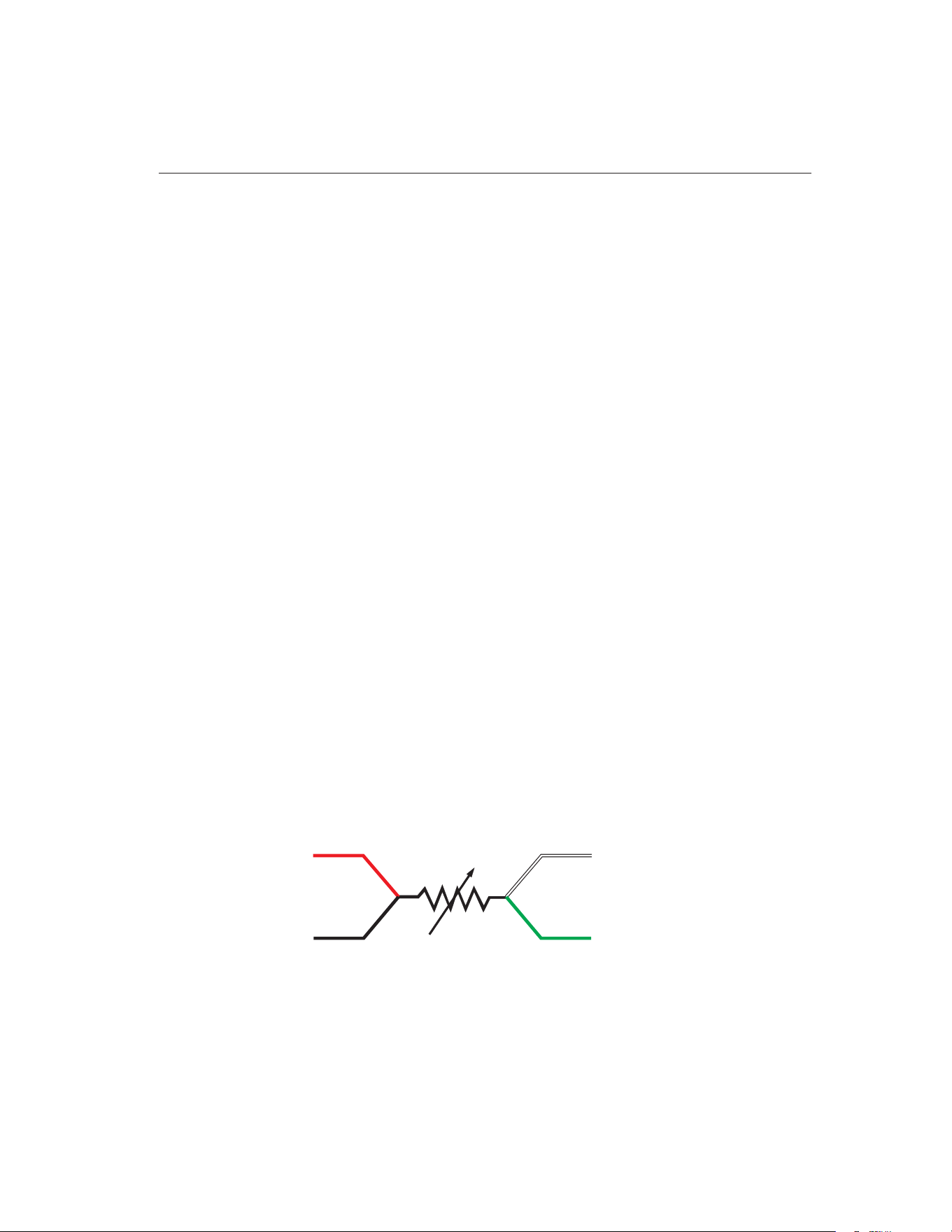
4.3 Lead Wire Identification
The 5608 and 5609 PRTs are equipped with a four-wire cable. The same
circuit schematic applies to both PRTs (see Figure 1). Four lead wires are
used to cancel lead wire resistance. For best results, the readout device
should be equipped to handle four-terminal resistors.
The lead wires are four different colors. Lead wire pairs attached to each
end of the sensor are identified as shown in Figure 1.
4
Installation
9
BLACK
RED
GREEN
WHITE
Figure 1 PRT Schematic
1.888.610.7664 sales@GlobalTestSupply.com
Fluke-Direct.com

5 PRT Care and Handling
Guidelines
5.1 PRT Care
CAUTION: READ THIS SECTION BEFORE REMOVING THE PRT
FROM THE SHIPPING BOX OR CASE
The 5608 and 5609 Platinum Resistance Thermometers (PRTs) are delicate
instruments. Care must be taken in handling the PRTs to maintain calibra-
tion accuracy. The stress free design of the PRT sensor reduces the effects of
mechanical shock. In addition, contamination problems of the sensor at high
temperature have been eliminated. However, care should still be used when
handling the PRT even though the Inconel sheath is durable and provides
good protection for the sensor. Correct handling of the PRT will prolong the
life expectancy. When not in use, the PRT should be stored in the protective
case.
Note: The PRT sheath changes color after use at high temperatures.
The PRT may arrive with a brown tint to the sheath due to calibration
at high temperatures.
The handle is not designed to be immersed. The temperature limits of the
handle are: –50°C to 200°C. Temperatures outside these limits can damage
the sealed portion of the handle and the connectors.
5.2 PRT Handling Guidelines
•
DO anneal the thermometer after shipment. Shipping the thermometer
can cause mechanical shocks that effect the accuracy of the thermome-
ter. Therefore, if possible, we advise that the thermometer be annealed
before use. The 5608 thermometer should be annealed at 500°C for
four hours. The 5609 at 660°C for four hours.
•
DO keep the thermometer as clean as possible. Always remove any
fluid from the sheath immediately after taking the thermometer from a
bath.
•
DO immerse the thermometer in the appropriate liquid for the temper-
ature range. If a dry block is used, the well diameter should allow the
PRT to comfortably slip in and out without excess movement. For best
results, immerse the thermometer as deep as possible to avoid “stem
effect” (the temperature error caused by the conduction of heat away
from the sensor). Do not submerge the handles.
11
5
PRT Care and Handling Guidelines
1.888.610.7664 sales@GlobalTestSupply.com
Fluke-Direct.com

•
DO allow sufficient time for the thermometer to stabilize before making
measurements. This allows for the best accuracy.
•
DO use the correct drive current with the thermometer to prevent error
in temperature or resistance. Hart Scientific recommends 1mA.
•
DO anneal the 5608 thermometer at 500°C and the 5609 thermome-
ter at 600 to 661°C for 12 hours if they become oxidized.
•
DO use the protective shipping box or case provided or other protec-
tion when the thermometer is not in use.
•
DO NOT subject the thermometer to any physical shock or vibration.
•
DO NOT use pliers or other devices to squeeze the sheath. This action
can permanently damage the PRT.
•
DO NOT subject the thermometer to temperatures above the highest
specified operating temperature.
•
DO NOT expose the thermometer’s handle or cables to extreme tem-
peratures. The temperature limits of the handle are: –50°C to 200°C
•
DO NOT submerge the handle or cable in liquids.
•
DO NOT screw a clamp down so tight that it dents the sheath. This can
permanently damage the PRT.
5608/5609
User’s Guide
12
1.888.610.7664 sales@GlobalTestSupply.com
Fluke-Direct.com

6 Operation
6.1 General
For best results, be familiar with the operation of the heat source and the
readout instrument. Be sure to follow the manufacturer’s instructions for the
readout instrument and the heat source.
6.2 Comparison Calibration of Other
Instruments
The uniformity and stability of the heat source and the degree of accuracy
required determine the number of temperature measurements necessary.
However, to follow “good” practice procedures, always measure the triple
point of water (R
tp
) after each temperature measurement. The following
equation provides the most accurate measurement of the ratio:
W
R
R
t
t
tp
=
All PRTs experience errors caused by self-heating of the element.
Self-heating is a combination of two factors, heat dissipation and heat sink.
Self-heating error can be reduced to have a negligible effect if the PRT is
used with the same excitation current and medium in which it was
calibrated.
6.3 Immersion Requirements
Stem effect can cause measurement errors for any thermometer. Errors pro-
duced by not following the immersion depth guidelines are due to heat lost
or gained by the sensing element through the thermometer stem. In addi-
tion, heat losses occur due to radiation losses from the sensing element to
the housing.
The immersion depth for standards is dependent on several factors includ-
ing accuracy requirements and type of liquid. Therefore, we recommend
minimum immersion depths as stated in the preceding paragraph and in the
specifications. However, remember the handle limitations. The handle is not
designed to be immersed. The temperature limits of the handle are –50°C to
200°C. Temperatures outside these limits can damage the handle. Convec-
tion of heat from the heat source must be kept within the handle limits.
The exact immersion depth required can be determined by performing a
gradient test taking measurements approximately every 1.27 cm (.5 inches)
until there is a significant difference in readings. Allow the thermometer to
stabilize at each new depth. Plot the results to see the stem effect.
13
6
Operation
1.888.610.7664 sales@GlobalTestSupply.com
Fluke-Direct.com

6.4 Thermal EMF
Two factors contribute to thermal EMF, chemical consistency and physical
consistency. Variations in chemical structure due to impurities can contrib-
ute to thermal EMF. Also discrepancies in crystal structure can contribute to
thermal EMF. These factors are minimized by annealing the full length of
wire before construction of the PRT.
Likewise, connection to extension lead wires and readout instruments can
beasourceofthermalEMF.ThethermalEMFiscausedbyadifferencein
temperature between two connections. If the two connections are the same
temperature, there will be little or no thermal EMF effects. However, if there
is a substantial temperature difference between connections, the thermal
EMF effects will be significant. Therefore, cover or insulate any exposed
bridge or galvanometer terminals to lessen the source of error. The effects of
thermal EMF can be canceled by using an AC bridge or a DC bridge with re-
versible current.
6.5 Transition Junction
Exceeding the temperature range of the transition junction will cause a
breach in the seal of the instrument. Maintaining the seal is critical to pre-
venting moisture from entering the device. If moisture penetrates the seal,
the PRT's short term repeatability, hysteresis, and insulation resistance may
be adversely affected. Insulation resistance also decreases rapidly as the
transition junction temperature increases, even if the seal is not broken.
When the insulation resistance becomes sufficiently low, performance suf-
fers. A good rule of thumb is that the transition junction is too hot when it is
hot enough to burn your thumb.
5608/5609
User’s Guide
14
1.888.610.7664 sales@GlobalTestSupply.com
Fluke-Direct.com
7 Accessories
7.1 Case Options
The 5608/5609 PRT comes in a rigid case appropriate for the length of the
probe.
•
Model 2601 protective case for thermometer probes 12 inches in
length or shorter.
•
Model 2609 protective case for thermometer probes 15 inches in
length or longer.
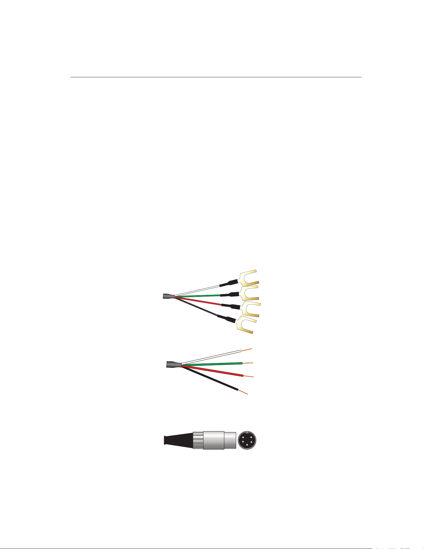
7.2 PRT Termination
The 5608/5609 PRT can be terminated in three ways (Figure 2) depending
on the user’s requirements:
•
Gold Plated Spade Lug
•
Bare Wire
•
5-Pin Din Connector
15
7
Accessories
Bare Wire
(customer option)
Spade Lug
(standard)
5-Pin DIN
(customer option)
1
2
4
5
3
Figure 2 Probe Termination Examples
1.888.610.7664 sales@GlobalTestSupply.com
Fluke-Direct.com

8
8.1
Troubleshooting
Troubleshooting
In the e
vent that the probe appears to function abnormally, this section may
be of use in solving the problem. Several possible problem conditions are
described along with likely causes and solutions. If a problem arises, please
read this section carefully and attempt to understand and solve the problem.
If the probe seems faulty or the problem cannot otherwise be solved, con-
tact an Authorized Service Center for assistance. Be sure to have the model
number and serial number of your probe available.
Problem Causes and Solutions
Data changes greater than
0.1°C are observed
•
Mechanical shock can cause temperature errors as great
as 0.5°C. If this is observed, first measure and record the
R
tp.
Next anneal the 5608 PRT at 500°C and the 5609
PRT at 660°C overnight. Measure the R
tp
again. The an-
nealing should decrease the R
tp
. If the R
tp
is stable,
recalibrate the PRT.
Data changes less than
0.1°C
•
Slight mechanical shock can cause temperature errors
less than 0.1°C. If this is observed, first measure and re-
cord the R
tp.
Next anneal the 5608 PRT at 500°C and the
5609 PRT at 660°C overnight. Measure the R
tp
again.
The annealing should decrease the R
tp
. Repeat the an-
nealing, R
tp
measurement cycle several times. When the
R
tp
is stable, recalibrate the PRT. If the R
tp
does not stabi-
lize, contact an Authorized Service Center (see Section
1.3).
•
Oxidation of the platinum sensor may occur after pro-
longed use between 200 and 450°C. This oxidation will
demonstrate itself by an increase in R
tp
of less than
0.1°C. To reduce the effects of oxidation, anneal the
5608 PRT at 500°C and the 5609 PRT at 600 to 661°C
overnight (12 hr.). Measure the R
tp
again. Repeat the an-
nealing, R
tp
measurement cycle several times This an-
nealing process should return R
tp
to within calibration
tolerances. If the R
tp
is within calibration tolerance, the
PRT is usable. If the R
tp
is not within calibration toler-
ance, but it is stable, recalibrate the PRT.
Data unstable
•
If the data is unstable at the Triple Point of Water (TPW),
check the connector. If the connector is correct, contact
an Authorized Service Center (see Section 1.3). The PRT
may be damaged and need repair.
•
If the data is unstable at high temperatures, it may be
due to electrical noise in the system. Reduce the temper-
ature and observe the data. If it is stable, electrical noise
is interfering with the measurements at high tempera
-
tures. Check the grounding of the readout device and
the heat source. A faulty ground on either device could
interfere with high temperature measurements. A
ground wire attached to the metal sheath of the PRT
may help to reduce electrical noise interference.
17
8
Troubleshooting
1.888.610.7664 sales@GlobalTestSupply.com
Fluke-Direct.com

Problem Causes and Solutions
Temperature readout differ
-
ent than expected, e.g. the
heat source is set at 300°C,
the PRT measures 275°C.
• Measure the PRT resistance at TPW.
• If the resistance of the PRT is less than the rated resis-
tance, e.g. 70Ω for the 5608/5609, there may be a short
in the sensor. Contact an Authorized Service Center.
• If the resistance of the PRT is only a few ohms, there
may be a short in the four lead-wires. Contact an Autho-
rized Service Center.
• If the PRT is open, the resistance will be “Out of Limits”
or in the kilohm or megohm range. Contact an Autho-
rized Service Center.
5608/5609
User’s Guide
18
1.888.610.7664 sales@GlobalTestSupply.com
Fluke-Direct.com