Loading ...
Loading ...
Loading ...
12 BRIGGSandSTRATTON.COM
Other Location Requirements
• Place the standby generator in a prepared location
that is flat and has provisions for water drainage.
• Install the standby generator in a location where
sump pump discharge, rain gutter down spouts, roof
run-off, landscape irrigation, or water sprinklers will
not flood the unit or spray the enclosure, or enter any
air inlet or outlet openings.
• Install the standby generator where it will not affect
or obstruct any utility services (including covered,
concealed, and underground), such as telephone,
electric, fuel (natural gas / LP), irrigation, air
conditioning, cable, septic, sewer, well, etc.
• Install the standby generator where leaves, grass,
snow, etc will not obstruct air inlet and outlet
openings. If prevailing winds will cause blowing or
drifting, a windbreak may be needed to protect the
unit.
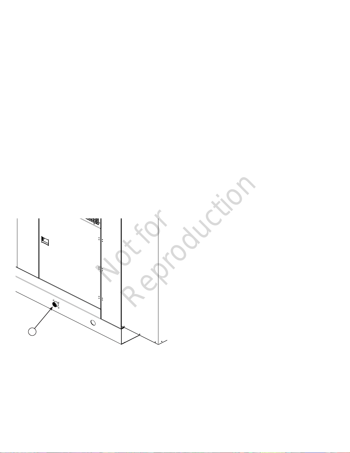
Electrical and Fuel Inlet Locations
A through-slab power cable stub-up is recommended. The
fuel inlet connector (A) is shown for reference.
Concrete Slab
The generator must be installed on a reinforced concrete
slab, constructed as follows:
• 28 day compression strength of 3000 psi (200 MPa)
• Minimum 5” (13 cm) thick
• Strengthen slab with No. 6 reinforcing bars on 12” (30.5
cm) centers or 8 ga. steel wire fabric with 6” (15 cm)
centers
• Avoid placing reinforcement in the entrance stub-up
area
The following dimensions will be needed to properly size and
configure the slab. Refer to figure at right:
A - Enclosure dimensions
• 130/200kW = 162" (412cm) long x 60" (152cm) wide
• 125/150kW = 135" (345cm) long x 52" (132cm) wide
• 80/100kW = 120" (305cm) long x 52" (132cm) wide
B - Generator mounting holes
• 130/200kW = 84" (213cm) long x 57.5" (146cm) wide
• 125/150kW = 80” (203 cm) long x 50” (127cm) wide
• 80/100kW = 66" (168cm) long x 50" (127cm) wide
C - Fuel inlet location
• 130/200kW = 78" (198cm)
• 125/150kW= 84" (213cm)
• 80/100kW = 85" (216cm)
D - Entrance stub-up area
• 130/200kW = 23.75” (60cm) long x 16.25” (41cm) wide
• 125/150kW= 23” (58cm) long x 12.5” (31cm) wide
• 100kW = 17.5” (44cm) long x 14.5” (36cm) wide
• 80kW = 19.5” (49cm) long x 14.5” (36cm) wide
D1 x D2 - Entrance stub-up location
• 130/200kW = 2.5” (6cm) x 18.75” (47cm)
• 125/150kW = 2” (5cm) x 14.5” (36cm)
• 100kW = 2” (5cm) x 16.5” (41cm)
• 80kW = 2” (5cm) x 16.5” (41cm)
F - Concrete Slab area
• 130/200kW = 168” (426cm) long x 108” (274cm) wide
• 125/150kW = 148” (376cm) long x 100” (254cm) wide
• 80/100kW = 138" (350cm) long x 100” (254cm) wide
A
Not for
Reproduction
Loading ...
Loading ...
Loading ...