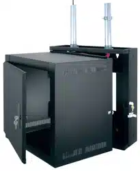
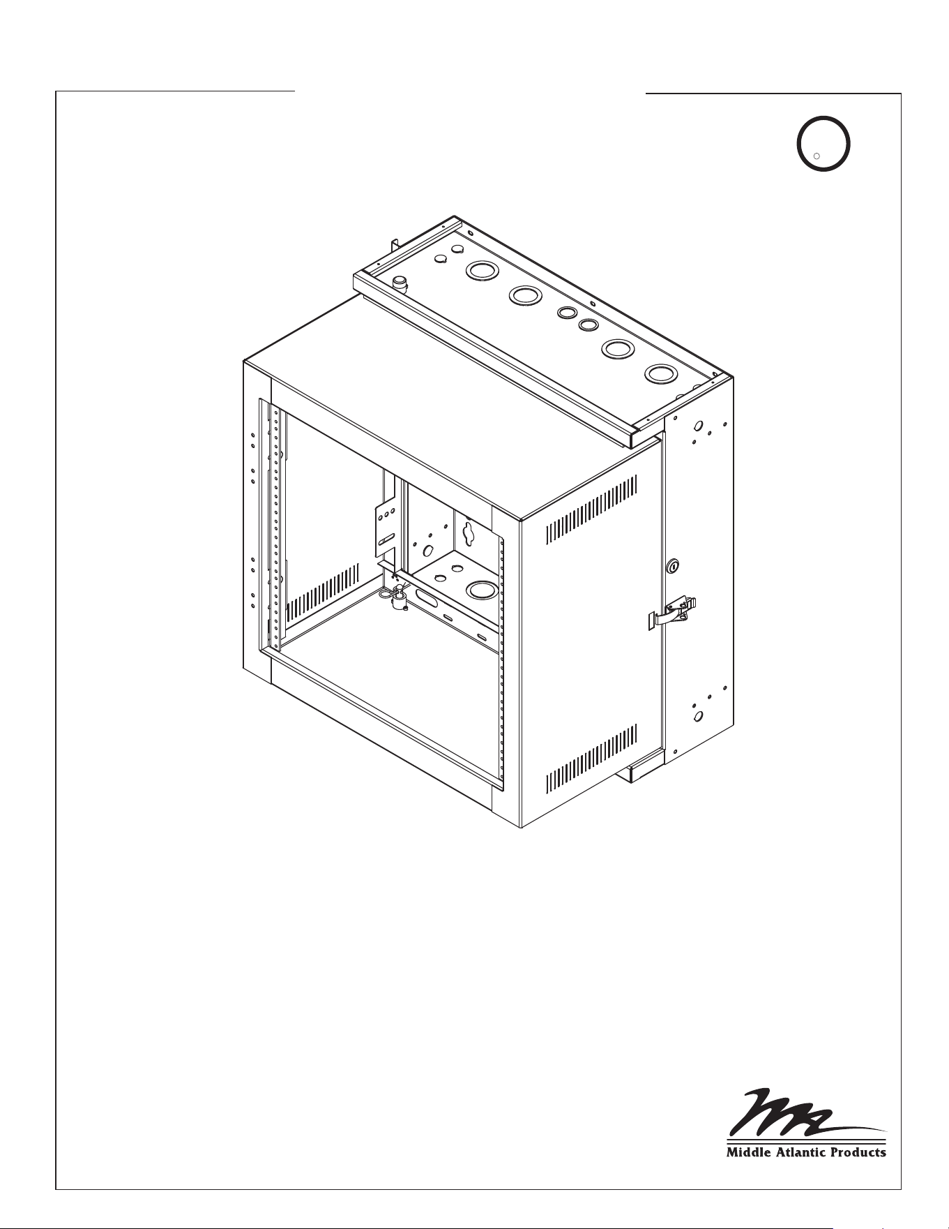
EWR SERIES
EWR WALL CABINET
Instruction Sheet
THANK YOU
Thank you for purchasing the EWR Wall Cabinet. Please read these instructions thoroughly
before installing / assembling this product.
PRODUCT FEATURES
- Ideal for both secure and non-secure areas
- Tool-free Quick-Mount system for easy one-person mounting of the
center section to the backpan
- Vented center section enables the effective passive thermal management
U
L
R
C US
LISTED
TM
I-00076 Rev J
CAUTION: TO REDUCE THE RISK OF PERSONAL INJURY AND CONFORM TO THE UL LISTING THESE
MOUNTING INSTRUCTIONS MUST BE FOLLOWED AND PROPER WEIGHT CAPACITY MUST BE
OBSERVED (SEE CHART BELOW). AS A GENERAL RULE, HEAVIER EQUIPMENT SHOULD BE PLACED
TOWARDS THE BOTTOM OF THE RACK.
PART # OF MOUNTING MAXIMUM WEIGHT
NUMBER HOLES CAPACITY
EWR-8-XX 4 150 lbs.
EWR-10-XX 4 150 lbs.
EWR-12-XX 4 150 lbs.
EWR-16-XX 4 150 lbs.
IMPORTANT SAFETY INSTRUCTIONS
IMPORTANT WARNINGS AND CAUTIONS!
WARNING! Failure to read, understand and follow the following information can result in serious personal injury, damage to the
equipment or voiding of the warranty.
!
• Read these instructions.
• Keep these instructions.
• Heed all warnings.
• Follow all instructions.
• Clean only with dry cloth.
• Only use attachments/accessories specified by the manufacturer.
Page 2
CAUTION: All installation and assembly steps must be performed by qualified personnel.
!
CAUTION: Ensure that the wall/floor has a structural load capacity that will support the weight of the cabinet fully loaded with
equipment.
!
CAUTION: Some parts of the enclosure system may not be effectively bonded to the Protective Earth Terminal (PET). If these parts
need to be bonded to the PET it should be done in accordance with Article 250 of the National Electrical Code.
!
CAUTION: Power cord(s), for fans or other accessories, need to be secured to ensure that they are routed away from pinch points
and moving parts.
!
CAUTION: Do not attempt to unload or move the enclosures alone. Make sure to have sufficient amount of personnel and
equipment to safely move this product.
!
CAUTION: The following parts are not effectively bonded to the protective earth terminal: Rackrails, lace bars, Lever Lock™,
shelving, baffles, blank panels, and cable management equipment. If any part needs to be bonded to the protective earth terminal
it shall be done in accordance with Article 250 of the National Electrical Code.
!
!
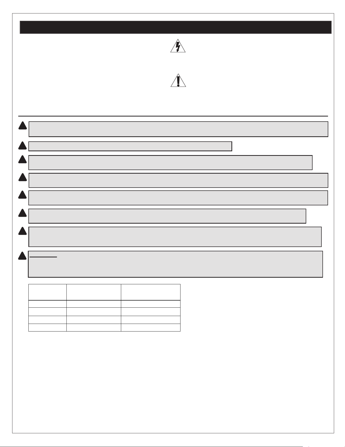
DANGER HAZARDOUS VOLTAGE
The lightning flash with the arrowhead symbol, within an equilateral
triangle is intended to alert the user to the presence of uninsulated
dangerous voltage within the product’s enclosure that may be of
sufficient magnitude to constitute a risk of electric shock to persons.
CAUTION
The exclamation point within an equilateral triangle is intended to
alert the user to the presence of important operating and maintenance
(servicing) instructions in the literature accompanying the appliance.
• Lisez ces instructions.
• Conservez ces instructions.
• Respectez tous les avertissements.
• Suivez toutes les instructions.
• Nettoyer avec un chiffon sec.
• Ne utilisez que des fixations / accessoires spécifiés par le fabricant.
CAPACITÉ DE CHARGE MAXIMALE
# MONTAGE DE TROUS
NUMÉRO DE PARTIE
ATTENTION! Ne pas lire, comprendre et suivre les informations suivantes peut entraîner des blessures graves, des dommages à la
l'équipement ou de la nullité de la garantie.
ATTENTION: Toutes installation et de montage étapes doivent être effectuées par du personnel qualifié.
ATTENTION: Se assurer que le mur / sol a une capacité de charge structurelle qui pourra supporter le poids de l'armoire
pleine charge avec équipement.
ATTENTION: Certaines parties du système d'enceinte ne peuvent pas être efficacement liés à la Terre de protection Terminal
(PET). Si ces pièces besoin d'être lié à l'animal, il doit être fait conformément à l'article 250 du Code national de l'électricité.
ATTENTION: Le cordon d'alimentation (s), pour les fans ou autres accessoires, doivent être fixés pour se assurer qu'ils sont
acheminés loin des points de pincement et des pièces en mouvement.
ATTENTION: Ne essayez pas de décharger ou déplacer les enceintes seul. Assurez-vous d'avoir suffisamment de
personnel et équipements pour déplacer ce produit en toute sécurité.
ATTENTION: Les pièces suivantes ne sont pas effectivement liés à la borne de terre de protection: crémaillères, aiguilles,
barres de dentelle, Lever Lock™, étagères, des chicanes, des panneaux vierges, et l'équipement de gestion des câbles. Si une
partie doit être lié à la borne de terre de protection il doit être fait conformément à l'article 250 du Code national de l'électricité.
!
!
!
!
!
!
!
!
Page 3
INSTRUCTIONS IMPORTAANTES SUR LA SÉCURITÉ
DANGER HAUTE TENSION
L'éclair avec le symbole de flèche dans un triangle équilatéral est
destiné à alerter l'utilisateur de la présence d'une tension dangereuse
non isolée dans l'enceinte du produit qui peut être d'une ampleur
suffisante pour constituer un risque de choc électrique pour les
personnes.
ATTENTION
Le point d'exclamation dans un triangle équilatéral est destiné à
alerter l'utilisateur de la présence d'importants instructions d’opération
et de maintenance (entretien) dans la documentation accompagnant
l'appareil.
EWR-8-XX 4 68 kg (150 lbs.)
EWR-10-XX 4 68 kg (150 lbs.)
EWR-12-XX 4 68 kg (150 lbs.)
EWR-16-XX 4 68 kg (150 lbs.)
!
ATTENTION: POUR RÉDUIRE LE RISQUE DE BLESSURES ET CONFORME AU UL INSCRIPTION DE CES
INSTRUCTIONS DE MONTAGE DOIVENT SUIVRE ET BONNE POIDS CAPACITÉ DOIT ÊTRE OBSERVÉE
(VOIR TABLEAU CI-DESSOUS ) . EN REGLE GENERALE , ÉQUIPEMENT PLACER LES PLUS LOURDS VERS
LE BAS DE LA GRILLE.
Page 3
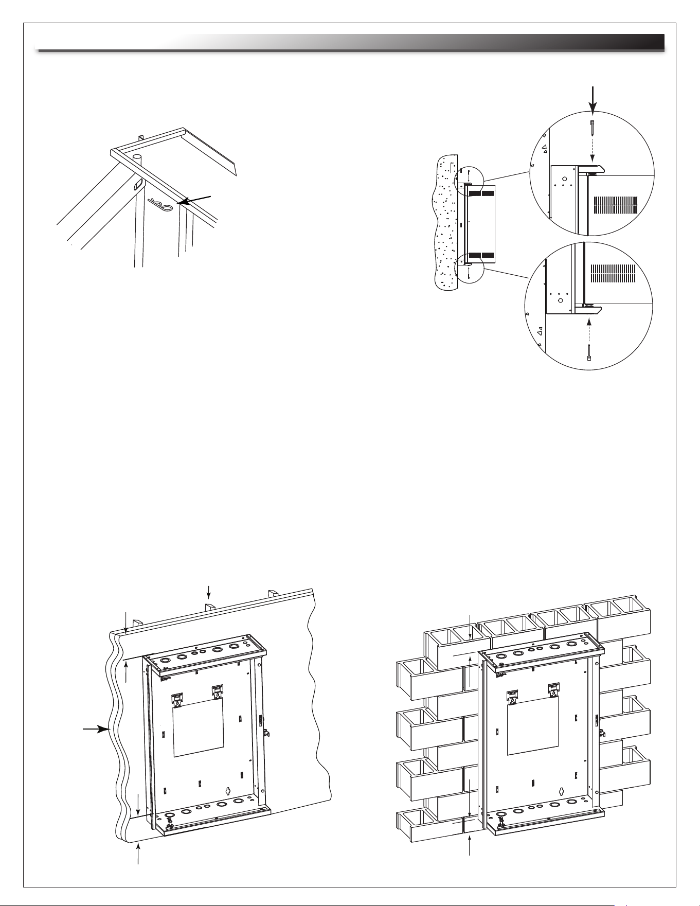
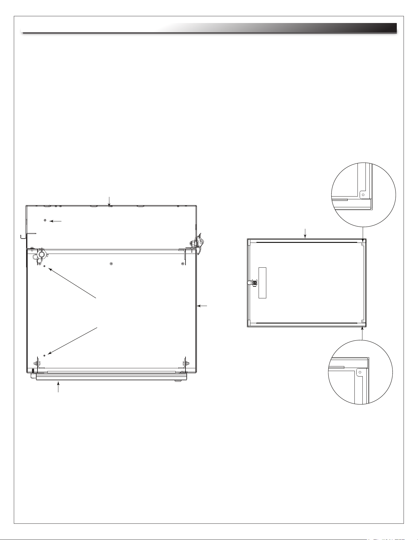
FIGURE A
1) Remove security clips located at top and bottom of unit. (FIGURE A)
2) Remove pivot pins located at the top and bottom of
backpan. (FIGURE B)
3) Separate backpan from center section and determine hinge side.
4) If mounting to backpan to wood framed wall, secure two
(2) 3/4"plywood sheets directly to wall studs. (FIGURE C)
NOTE: A minimum 4” clearance above and below rack is required.
5) Using 3/8” toggle bolts and standard flat washers, mount backpan to plywood. (FIGURE C)
NOTE: Unit must be installed plumb and level.
NOTE: All mounting holes must be used.
NOTE: The mounting methods outlined below can be used for all model EWRs.
NOTE: EWR can be mounted to block wall.
(Installation not evaluated by UL)
MINIMUM 4”
CLEARANCE
STUD
3/4”
PLYWOOD
SHEETS
(2)
FIGURE B
PIVOT PIN
SECURITY CLIP
MINIMUM 4”
CLEARANCE
MINIMUM 4”CLEARANCE
MINIMUM 4” CLEARANCE
FIGURE C
INSTALLATION
NOTE: EWR center section can be opened from left-to-right or vice
versa depending on how backpan is installed.
NOTE: When installing front door, factory rackrail
setback will be 1-1/2" to the inside of the door. The
lock and handle located at the center of the door will
have an additional setback of 1/2". Please adjust
rackrail accordingly before installing equipment.
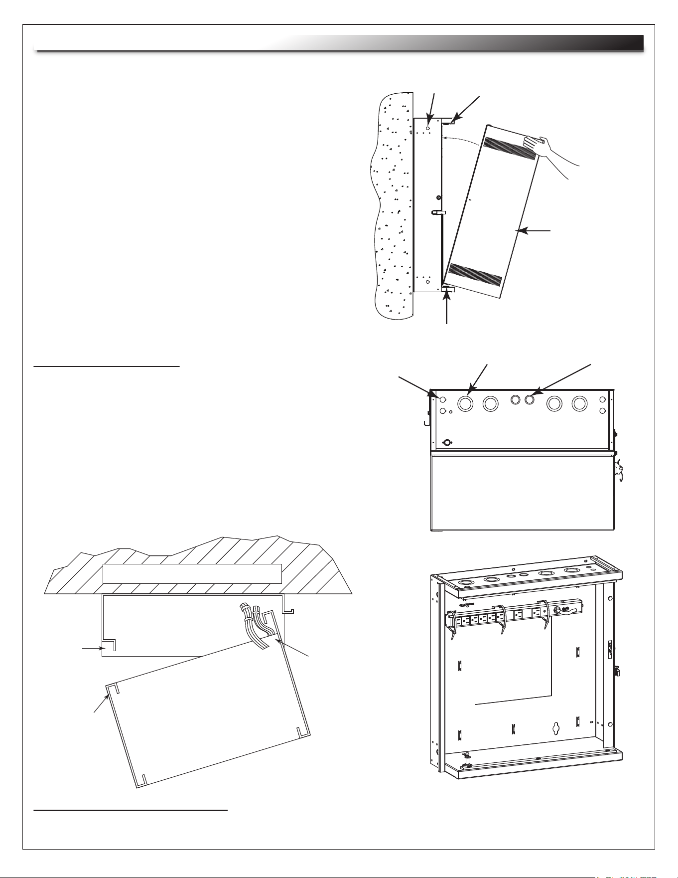
FIGURE D
PLACE HAND
HERE TO PIVOT
INTO PLACE
BACKPAN
Page 4
MOUNTING WALL
BACKPAN
PINCH
POINT
DO NOT
DRESS
WIRES ON
THIS SIDE
DRESS WIRES
AS SHOWN
ON PIVOT SIDE
CABLE MANAGEMENT
1" AND 1-1/2" EKO 1/2" AND 3/4" EKOUHF/VHF ANTENNA
KO 5/8"
TOP VIEW
6) Align bottom of center section with lower
pivot bushing on backpan. (FIGURE D)
7) Pivot top of center section into backpan and
align with upper pivot bushing. (FIGURE D)
8) Insert pivot pin into upper bushing, hand tighten
fully and then back out one turn. Repeat for lower
bushing.
9) Install the security clips to prevent removal of pivot
pins from exterior of enclosure. (FIGURE A)
FIGURE D
CENTER
SECTION
• Slots are provided on top and bottom of center
section for hook and loop.
• Bridge lances are provided on backpan for cable
management.
• 10-1/2" x 10-1/2" opening in the center of the backpan
for large electrical boxes. (FIGURE X)
• Knockouts are provided in the top/bottom for electrical
fittings, UHF/VHF antennae & cable entry.
UPPER PIVOT BUSHING
UPPER PIVOT BUSHING
POWER STRIP INSTALLATION
NOTE: For mounting PD-815SC / PD-815SC-NS Slim Power Strip, wire tie to bridge lances. (FIGURE D)
CENTER
SECTION
INSTALLATION (Continued)
GROUNDING AND BONDING
Protective Earth Terminals (PET) are located in backpan of the wall rack. These terminals are marked with the symbol
Wall rack parts, center section and door, contain or are provided with bonding points for connection to the backpan / PET.
Protective earth and bonding connections shall be in accordance with Article 250 of the National Electric Code.
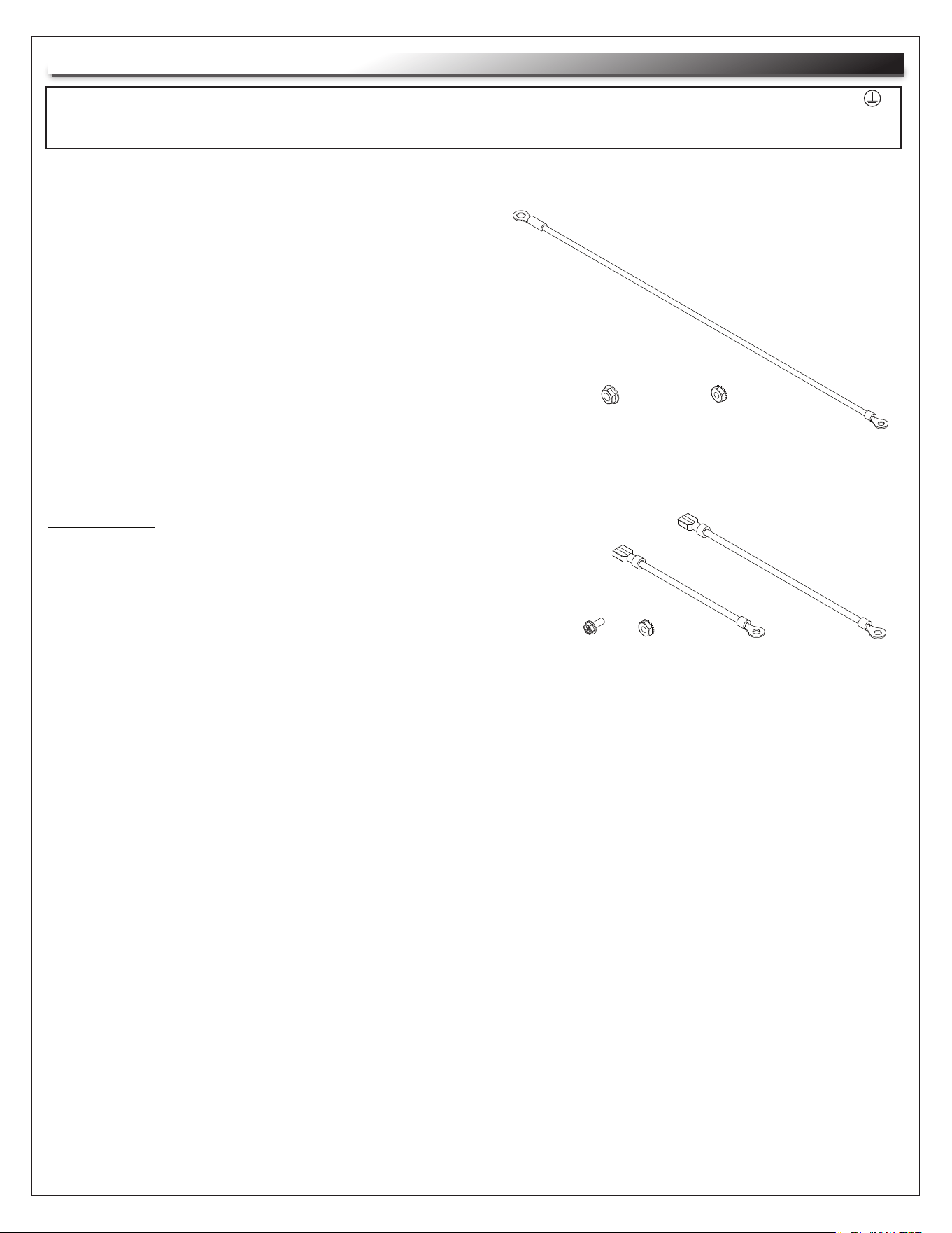
PARTS LIST
• Backpan bonding wire [12 Gauge Wire
(#10 ring terminal to 1/4” ring terminal] 14”]
• Flange Nut 1/4-20
• Locking Nut 10-32
QTY
(1)
(1)
(1)
(1) (1)
(1)
(1)
(1)
Page 5
OPTIONAL PROTECTIVE EARTH TERMINAL KIT: #PET-K-D/EWR
OPTIONAL PROTECTIVE EARTH TERMINAL KIT: #PET-K-D/EWRD
PARTS LIST
• Door bonding wire [12 Gauge Wire
(#10 ring terminal to male disconnect) 6”]
• Door bonding wire [12 Gauge Wire
(#10 ring terminal to female disconnect) 4”]
• Thread forming screw M4 x .7
• Locking Nut 10-32
QTY
(1)
(1)
(1)
(1)
(1)
(1)
Page 6
GROUNDING AND BONDING
Center
Section
Backpan
Door
Center Section Bonding Studs
10-32 (2 Upper and 2 Lower)
Backpan PET Stud
Door Bonding Points
(1 Upper and 1 Lower)
1) Attach backpan bonding wire from 1/4”-20 backpan protective earth terminal (PET) to nearest
center section bonding stud (10-32) using hardware provided. (FIGURE G)
NOTE: The main protective earth ground needs to be the first terminal placed on the PET and this
terminal needs to be secured on its own with a nut. The bonding wire for the center section can
be added to the PET after securing the nut for the main ground. (FIGURE G)
2) FOR OPTIONAL DOOR: Attach door bonding wire (with male or female disconnect end) to door
bonding point with self-tapping screw (included). (FIGURE G)
3) Attach remaining door bonding wire to nearestcenter section bonding stud (10-32) using hardware
provided. (FIGURE G)
4) Connect male and female ends of door bonding wire set.
FIGURE G
OVERHEAD VIEW
FRONT VIEW
Door
WARRANTY
Middle Atlantic Products (the "Company") warrants the EWR Seriers EWR Wall Cabinet to be free from defects in material or workmanship
under normal use and conditions for the lifetime of the product.
The Company's entire liability to the purchaser, and the purchaser's (or any other party's) sole and exclusive remedy, under this warranty
shall be limited, at the Company's option, to either (a) return of and refund of the price paid for, or (b) repair or replacement at the
Company's factory of the products purchased, or any part or parts thereof, which the Company has determined to be defective after
inspection thereof at the Company's factory.
This warranty does not cover damage due to acts of God, accident, misuse, abuse or negligence by parties other than the Company, or
any modification or alteration of the products. In addition, this warranty does not cover damage due to improper handling, assembly,
installation or maintenance.
THIS WARRANTY IS IN LIEU OF ALL OTHER WARRANTIES OF ANY KIND, EITHER EXPRESSED OR IMPLIED, INCLUDING, BUT
NOT LIMITED TO, IMPLIED WARRANTIES OF MERCHANTABILITY AND FITNESS FOR A PARTICULAR PURPOSE.
TO THE MAXIMUM EXTENT PERMITTED BY APPLICABLE LAW, IN NO EVENT SHALL THE COMPANY BE LIABLE FOR ANY
SPECIAL, INCIDENTAL, INDIRECT, OR CONSEQUENTIAL DAMAGES WHATSOEVER (INCLUDING, WITHOUT LIMITATION,
DAMAGES FOR LOSS OF BUSINESS PROFITS, BUSINESS INTERRUPTION OR ANY OTHER PECUNIARY LOSS) ARISING OUT OF
THE USE OF THE PRODUCTS PURCHASED, EVEN IF THE COMPANY HAS BEEN ADVISED OF THE POSSIBILITY OF SUCH
DAMAGES. THE COMPANY'S LIABILITY TO THE PURCHASER (OR ANY OTHER PARTY) HEREUNDER, IF ANY, SHALL IN NO
EVENT EXCEED THE PURCHASE PRICE OF THE PRODUCTS PAID TO THE COMPANY.
Corporate Headquarters
Corporate Voice 973-839-1011 - Fax 973-839-1976 / International Voice +1 973-839-8821 - Fax +1 973-839-4982
middleatlantic.com - [email protected]
Middle Atlantic Canada
Voice 613-836-2501 - Fax 613-836-2690 / middleatlantic.ca - [email protected]
Factory Distribution
USA: NJ - CA - IL Canada: ON - BC
At Middle Atlantic Products we are always listening. Your comments are welcome.
Middle Atlantic Products is an ISO 9001 and ISO 14001 Registered Company.