Loading ...
Loading ...
Loading ...
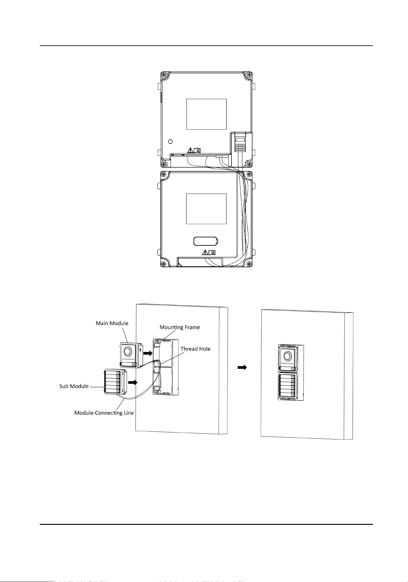
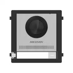
Figure 4-18 Line Connecon Eect Picture
7.
Insert the modules into the frame aer wiring. The main unit must be placed in the top grid.
Figure 4-19 Insert the Modules
8.
Use the hexagon wrench in the package to x the cover onto the frame.
DS-KD8003 Series Module Door Staon User Manual
33
Loading ...
Loading ...
Loading ...