
Network PTZ Camera·Quick Start Guide
i
Network PTZ Camera
Quick Start Guide

Network PTZ Camera·Quick Start Guide
i
Quick Start Guide
COPYRIGHT © 2018 Hangzhou Hikvision Digital Technology Co., Ltd.
ALL RIGHTS RESERVED.
Any and all information, including, among others, wordings, pictures,
graphs are the properties of Hangzhou Hikvision Digital Technology
Co., Ltd. or its subsidiaries (hereinafter referred to be “Hikvision”).
This user manual (hereinafter referred to be “the Manual”) cannot
be reproduced, changed, translated, or distributed, partially or
wholly, by any means, without the prior written permission of
Hikvision. Unless otherwise stipulated, Hikvision does not make any
warranties, guarantees or representations, express or implied,
regarding to the Manual.
About this Manual
This Manual is applicable to Network PTZ Camera.
The Manual includes instructions for using and managing the
product. Pictures, charts, images and all other information
hereinafter are for description and explanation only. The
information contained in the Manual is subject to change, without
notice, due to firmware updates or other reasons. Please find the
latest version in the company website
(http://overseas.hikvision.com/en/).
Please use this user manual under the guidance of professionals.
Trademarks Acknowledgement
and other Hikvision’s trademarks and logos are the
properties of Hikvision in various jurisdictions. Other trademarks and
logos mentioned below are the properties of their respective
owners.

Network PTZ Camera·Quick Start Guide
ii
Legal Disclaimer
TO THE MAXIMUM EXTENT PERMITTED BY APPLICABLE LAW, THE
PRODUCT DESCRIBED, WITH ITS HARDWARE, SOFTWARE AND
FIRMWARE, IS PROVIDED “AS IS”, WITH ALL FAULTS AND ERRORS,
AND HIKVISION MAKES NO WARRANTIES, EXPRESS OR IMPLIED,
INCLUDING WITHOUT LIMITATION, MERCHANTABILITY,
SATISFACTORY QUALITY, FITNESS FOR A PARTICULAR PURPOSE, AND
NON-INFRINGEMENT OF THIRD PARTY. IN NO EVENT WILL HIKVISION,
ITS DIRECTORS, OFFICERS, EMPLOYEES, OR AGENTS BE LIABLE TO
YOU FOR ANY SPECIAL, CONSEQUENTIAL, INCIDENTAL, OR INDIRECT
DAMAGES, INCLUDING, AMONG OTHERS, DAMAGES FOR LOSS OF
BUSINESS PROFITS, BUSINESS INTERRUPTION, OR LOSS OF DATA OR
DOCUMENTATION, IN CONNECTION WITH THE USE OF THIS
PRODUCT, EVEN IF HIKVISION HAS BEEN ADVISED OF THE
POSSIBILITY OF SUCH DAMAGES.
REGARDING TO THE PRODUCT WITH INTERNET ACCESS, THE USE OF
PRODUCT SHALL BE WHOLLY AT YOUR OWN RISKS. HIKVISION SHALL
NOT TAKE ANY RESPONSIBILITES FOR ABNORMAL OPERATION,
PRIVACY LEAKAGE OR OTHER DAMAGES RESULTING FROM CYBER
ATTACK, HACKER ATTACK, VIRUS INSPECTION, OR OTHER INTERNET
SECURITY RISKS; HOWEVER, HIKVISION WILL PROVIDE TIMELY
TECHNICAL SUPPORT IF REQUIRED.
SURVEILLANCE LAWS VARY BY JURISDICTION. PLEASE CHECK ALL
RELEVANT LAWS IN YOUR JURISDICTION BEFORE USING THIS
PRODUCT IN ORDER TO ENSURE THAT YOUR USE CONFORMS THE
APPLICABLE LAW. HIKVISION SHALL NOT BE LIABLE IN THE EVENT
THAT THIS PRODUCT IS USED WITH ILLEGITIMATE PURPOSES.

Network PTZ Camera·Quick Start Guide
iii
IN THE EVENT OF ANY CONFLICTS BETWEEN THIS MANUAL AND THE
APPLICABLE LAW, THE LATER PREVAILS.
0505071080803

Network PTZ Camera·Quick Start Guide
iv
Regulatory Information
FCC Information
Please take attention that changes or modification not expressly
approved by the party responsible for compliance could void the
user’s authority to operate the equipment.
FCC compliance: This equipment has been tested and found to
comply with the limits for a Class A digital device, pursuant to part
15 of the FCC Rules. These limits are designed to provide reasonable
protection against harmful interference when the equipment is
operated in a commercial environment. This equipment generates,
uses, and can radiate radio frequency energy and, if not installed and
used in accordance with the instruction manual, may cause harmful
interference to radio communications. Operation of this equipment
in a residential area is likely to cause harmful interference in which
case the user will be required to correct the interference at his own
expense.
FCC Conditions
This device complies with part 15 of the FCC Rules. Operation is
subject to the following two conditions:
1. This device may not cause harmful interference.
2. This device must accept any interference received, including
interference that may cause undesired operation.
EU Conformity Statement
This product and - if applicable - the supplied
accessories too are marked with "CE" and comply
therefore with the applicable harmonized European
standards listed under the Low Voltage Directive
Network PTZ Camera·Quick Start Guide
v
2015/35/EU, the EMC Directive 2014/30/EU, the RoHS Directive
2011/65/EU.
2012/19/EU (WEEE directive): Products marked
with this symbol cannot be disposed of as unsorted
municipal waste in the European Union. For proper
recycling, return this product to your local supplier
upon the purchase of equivalent new equipment,
or dispose of it at designated collection points. For more information,
please see: www.recyclethis.info.
2006/66/EC (battery directive): This product
contains a battery that cannot be disposed of as
unsorted municipal waste in the European Union.
See the product documentation for specific battery
information. The battery is marked with this symbol,
which may include lettering to indicate cadmium (Cd), lead (Pb), or
mercury (Hg). For proper recycling, return the battery to your
supplier or to a designated collection point. For more information,
please see: www.recyclethis.info.
Industry Canada ICES-003 Compliance
This device meets the CAN ICES-3 (A)/NMB-3(A) standards
requirements.
Network PTZ Camera·Quick Start Guide
vi
Safety Instruction
These instructions are intended to ensure that user can use the
product correctly to avoid danger or property loss.
The precaution measure is divided into “Warnings” and “Cautions”
Warnings: Serious injury or death may occur if any of the warnings
are neglected.
Cautions: Injury or equipment damage may occur if any of the
cautions are neglected.
Warnings
In the use of the product, you must be in strict compliance with
the electrical safety regulations of the nation and region.
Refer to technical specifications for detailed information.
Input voltage should meet both the SELV (Safety Extra Low Voltage)
and the Limited Power Source with 24 VAC or 12 VDC according to
the IEC60950-1 standard. Refer to technical specifications for
detailed information.
Warnings Follow these
safeguards to prevent
serious injury or death.
Cautions Follow these
precautions to prevent
potential injury or material
damage.
Network PTZ Camera·Quick Start Guide
vii
Do not connect several devices to one power adapter as adapter
overload may cause over-heating or a fire hazard.
Make sure that the plug is firmly connected to the power socket.
Make sure that the power has been disconnected before you wire,
install or dismantle the PTZ camera.
When the product is mounted on wall or ceiling, the device shall
be firmly fixed.
If smoke, odor or noise rise from the device, turn off the power at
once and unplug the power cable, and then contact the service
center.
If the product does not work properly, contact your dealer or the
nearest service center. Never attempt to disassemble the camera
yourself. (We shall not assume any responsibility for problems
caused by unauthorized repair or maintenance.)
Cautions
If the camera fails to synchronize local time with that of the
network, you need to set up camera time manually. Visit the
camera (via web browser or client software) and enter system
settings interface for time settings.
Make sure the power supply voltage is correct before using the
camera.
Do not drop the camera or subject it to physical shock, and do not
expose it to high electromagnetism radiation. Avoid installation on
vibrations surface or places subject to shock (ignorance can cause
device damage).

Network PTZ Camera·Quick Start Guide
viii
Do not touch senor modules with fingers. If cleaning is necessary,
use clean cloth with a bit of ethanol and wipe it gently. If the
camera will not be used for an extended period, replace the lens
cap to protect the sensor from dirt.
Do not aim the camera at the sun or extra bright places. Blooming
or smearing may occur otherwise (which is not a malfunction),
and affect the endurance of sensor at the same time.
The sensor may be burned out by a laser beam, so when any laser
equipment is in using, make sure that the surface of sensor will
not be exposed to the laser beam.
Do not place the camera in extremely hot, cold, dusty or damp
locations, and do not expose it to high electromagnetic radiation.
To avoid heat accumulation, good ventilation is required for
operating environment.
Keep the camera away from liquid while in use.
While in delivery, the camera shall be packed in its original packing,
or packing of the same texture.
Improper use or replacement of the battery may result in hazard
of explosion. Replace with the same or equivalent type only.
Dispose of used batteries according to the instructions provided
by the battery manufacturer.

Network PTZ Camera·Quick Start Guide
ix
Table of Contents
1 Overview ......................................................................................... 1
1.1 Introduction ............................................................................. 1
1.2 Cable Descriptions .................................................................... 1
1.3 Alarm Output............................................................................ 2
2 Installation ...................................................................................... 4
2.1 Installing the Memory Card ...................................................... 4
2.1.1 DE1Axxx(I) Series PTZ Camera ........................................... 4
2.1.2 DE2Axxx(I) Series PTZ Camera ........................................... 7
2.1.3 DE2xxx(I) Series PTZ Camera ............................................. 7
2.1.4 DE3xxx Series PTZ Camera ................................................. 8
2.1.5 DY3xxx Series PTZ Bullet Camera ....................................... 9
2.1.6 DE4AxxxI Series PTZ Camera .............................................. 9
2.2 Installing DE1Axxx(I) Series PTZ Camera ................................. 11
2.2.1 Ceiling Mounting ............................................................. 11
2.2.2 Wall Mounting ................................................................. 13
2.3 Installing DE2Axxx(I) Series PTZ Camera ................................. 16
2.4 Installing DE2xxx(I) Series PTZ Camera .................................... 16
2.4.1 Wall Mounting ................................................................. 16
2.4.2 Ceiling Mounting ............................................................. 20
2.4.3 Installing with Junction Box ............................................. 25
2.5 Installing DE3xxx Series PTZ Camera ....................................... 28
2.5.1 Ceiling Mounting ............................................................. 28
2.5.2 In-ceiling Mounting ......................................................... 30
2.6 Installing DY3xxx Series PTZ Bullet Camera ............................. 33
2.6.1 Dimensions of DY3xxx Series PTZ Bullet Camera.............. 33
2.6.2 Wall Mounting ................................................................. 34
2.6.3 Base Mounting ................................................................ 36

Network PTZ Camera·Quick Start Guide
x
2.7 Installing DE4AxxxI Series PTZ Camera .................................... 37
2.7.1 Ceiling Mounting ............................................................. 37
2.7.2 In-ceiling Mounting ......................................................... 38
3 Setting the PTZ Camera over the LAN........................................... 41
3.1 Wiring .................................................................................... 41
3.2 Activating the Camera ............................................................ 42
3.2.1 Activation via Web Browser ............................................. 42
3.2.2 Activation via SADP Software .......................................... 44
3.3 Modifying the IP Address ........................................................ 45
4 Accessing via Web Browser .......................................................... 48
5 Operating via Hik-Connect App .................................................... 51
5.1 Enable Hik-Connect Service on Camera .................................. 51
5.1.1 Enable Hik-Connect Service via SADP Software ............... 51
5.1.2 Enable Hik-Connect Service via Web Browser ................. 52
5.2 Hik-Connect Setup .................................................................. 54
5.3 Adding Camera to Hik-Connect ............................................... 54
5.4 Initializing the Memory Card .................................................. 56

Network PTZ Camera·Quick Start Guide
1
1 Overview
1.1 Introduction
The network PTZ camera has the following series:
DE1Axxx(I) Series PTZ Camera
DE2Axxx(I) Series PTZ Camera
DE2xxx(I) Series PTZ Camera
DE3xxx Series PTZ Camera
DY3xxx Series PTZ Bullet Camera
DE4AxxxI Series PTZ Camera
Integrated with an optical zoom lens, this series of cameras feature
in the PTZ limits, 3D positioning, Day/Night auto switch, 3D DNR, etc.,
and are widely applied in various kinds of environments.
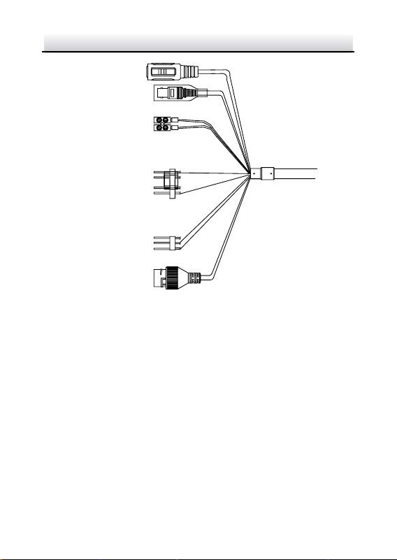
1.2 Cable Descriptions
The cable interfaces of network PTZ camera are shown in Figure 1-1.
The cables are distinguished by different colors. Refer to the labels
attached on the cables for identification.
Notes:
The cables vary depending on different camera models.
Make sure the camera is power-off before you connect the
cables.
Network PTZ Camera·Quick Start Guide
2
Network Cable
Video Cable
Power Cord
.
.
.
DC12V IN
RS-485
Alarm Cable
Audio Cable
Figure 1-1 Cables of PTZ Camera
Power Cord: Supports 12 VDC power supply.
Video Cable: Connect BNC Cable to test the video output.
Alarm Cable: Connect terminal ALARM-IN with GND interface,
and connect terminal ALARM-OUT with ALARM-COM interface.
Audio Cable: Connect terminal AUDIO-IN with GND interface.
Network Cable: Connect the network interface with network
cable.
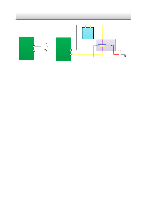
1.3 Alarm Output
Alarm output is shown in Figure 1-2.
Network PTZ Camera·Quick Start Guide
3
Relay Output
OUT (n)
DC
OUT (n)
Direct load
+
-
Relay Output
OUT (n)
OUT (n)
DC 30V
1A
Power Supply
GND Output
~220V AC
FireWire
Zero
Line
JQC-3FG
Relay
(10A 250VAC)
Figure 1-2 Alarm Output

Network PTZ Camera·Quick Start Guide
4
2 Installation
Before you start:
Check the package contents and make sure that the device in the
package is in good condition and all the assembly parts are included.
Notes:
Do not drag the PTZ camera with its waterproof cables;
otherwise the waterproof performance is affected.
Do not touch the bubble directly by hand. The image blurs
otherwise.
Do not power up the camera until the installation is finished. To
ensure the safety of personnel and equipment, all the
installation steps should be done with power supply off.
2.1 Installing the Memory Card
You can install the memory card for local storage.
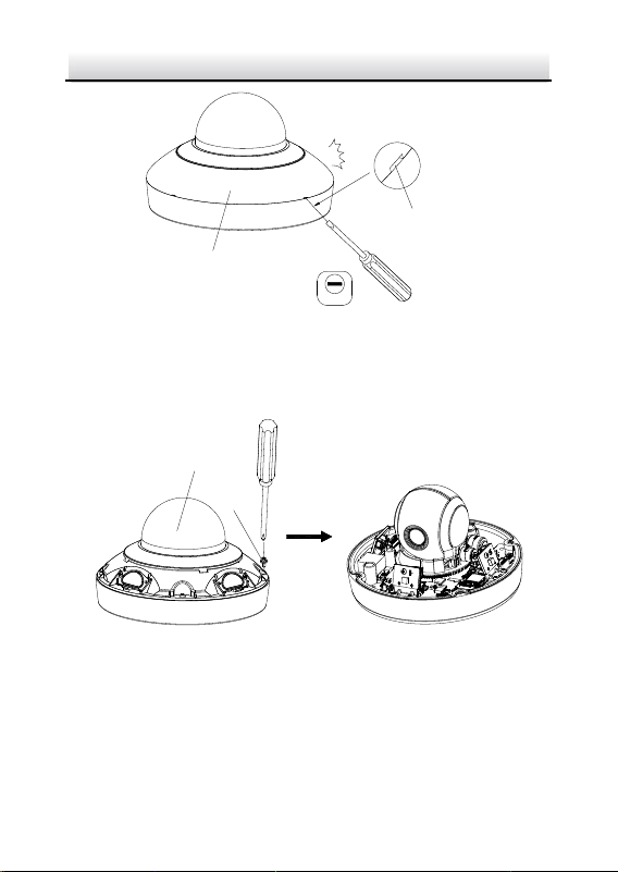
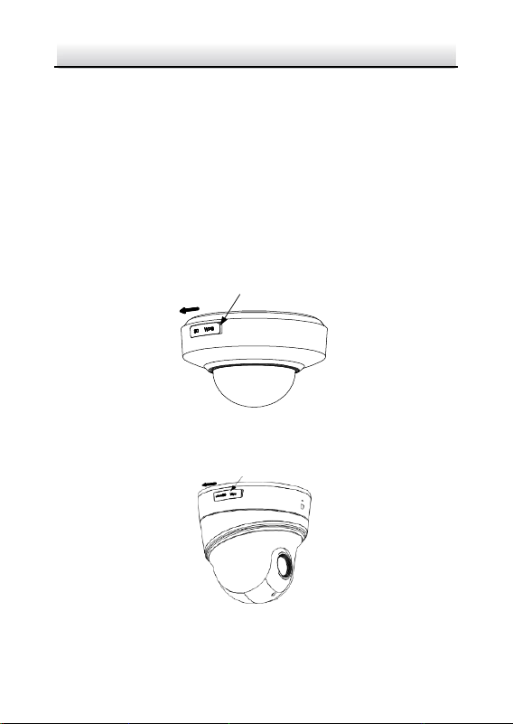
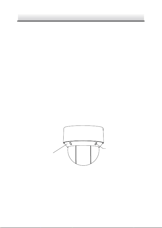
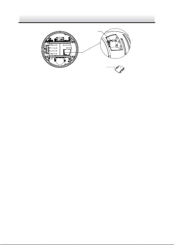
2.1.1 DE1Axxx(I) Series PTZ Camera
Steps:
1. Open the cover with the straight screwdriver from a crack on the
cover, as shown in Figure 2-1.
Network PTZ Camera·Quick Start Guide
5
2.0
Cover
Crack
Figure 2-1 Open the Cover
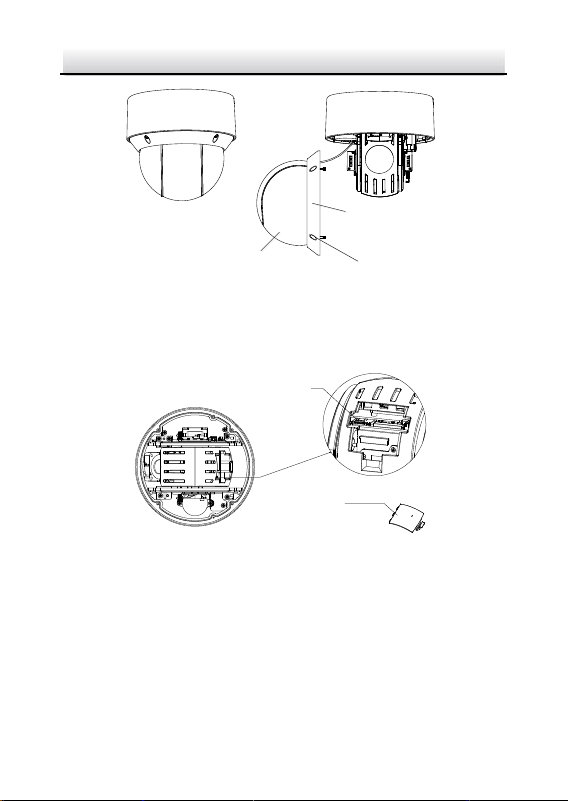
2. Unscrew the screws on the camera base with the cross
screwdriver, and remove the bubble, as shown in Figure 2-2.
Bubble
Screw
Figure 2-2 Remove the Bubble
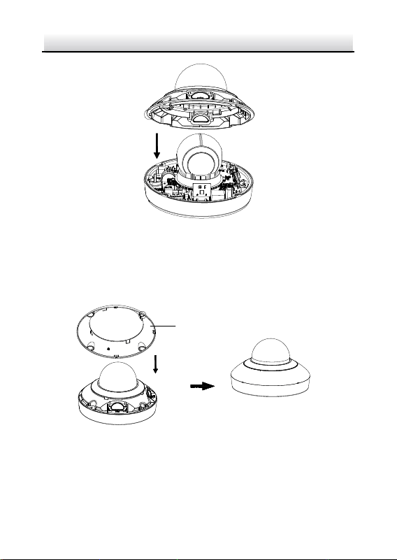
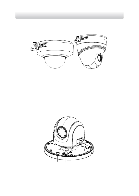
3. Open the memory card slot in the camera, and insert the memory
card.
4. Align the bubble with the camera base, and install the bubble
back. Fix the bubble with four screws, as shown in Figure 2-3.
Network PTZ Camera·Quick Start Guide
7
2.1.2 DE2Axxx(I) Series PTZ Camera
Note:
The installation steps are similar to the installation steps of
DE1Axxx(I) series camera. Refer to section 2.1.1 DE1Axxx(I) Series
PTZ Camera.
2.1.3 DE2xxx(I) Series PTZ Camera
Steps:
1. Open the memory card cover.
Memory Card Cover
Figure 2-5 DE2xxx Series PTZ Camera
Memory Card Cover
Figure 2-6 DE2xxxI Series (IR) PTZ Camera
Network PTZ Camera·Quick Start Guide
8
2. Rotate the cover to a proper position, align the memory card with
the memory card slot and insert it.
Figure 2-7 Insert the Memory Card
3. Rotate the cover and push it back.
2.1.4 DE3xxx Series PTZ Camera
Steps:
1. Loosen three screws on the bottom of camera to reveal the
memory card slot, as shown in Figure 2-8.
Reset
Debug Memory Card
Figure 2-8 DE3xxx Series PTZ Camera
Network PTZ Camera·Quick Start Guide
9
2. Align the memory card with the memory card slot and insert it.
3. Fix the screws and assemble the PTZ camera.
2.1.5 DY3xxx Series PTZ Bullet Camera
For DY3xxx series PTZ bullet camera, the memory card slot is in the
camera module and if you need, the memory card can be installed
before the camera leaves the factory. In order to prevent damage,
we highly recommend that you do not disassemble the PTZ bullet
camera by yourself.
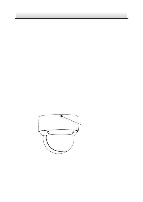
2.1.6 DE4AxxxI Series PTZ Camera
Steps:
1. Remove the four silicone plugs on the decorative rim as shown in
Figure 2-9, and you can see four flange screws in the decorative
rim.
Silicone Plug
Decorative Rim
Figure 2-9 Remove the Silicone Plugs
2. Loosen four flange screws with a screwdriver. Remove the bubble
and the decorative rim as shown in Figure 2-10.
Network PTZ Camera·Quick Start Guide
10
Bubble
Flange Srews
Decorative Rim
Figure 2-10 Remove the Bubble and the Decorative Rim
3. Open the memory card cover and insert the memory card into the
card slot as shown in Figure 2-11 and Figure 2-12.
Memory Card Slot
Memory Card Cover
Figure 2-11 For 20× Camera Module
Network PTZ Camera·Quick Start Guide
11
Memory Card Slot
Memory Card Cover
Figure 2-12 For 4× Camera Module
4. Close the memory card cover. Fix the four flange screws and push
four silicone plugs back to assemble the PTZ camera.
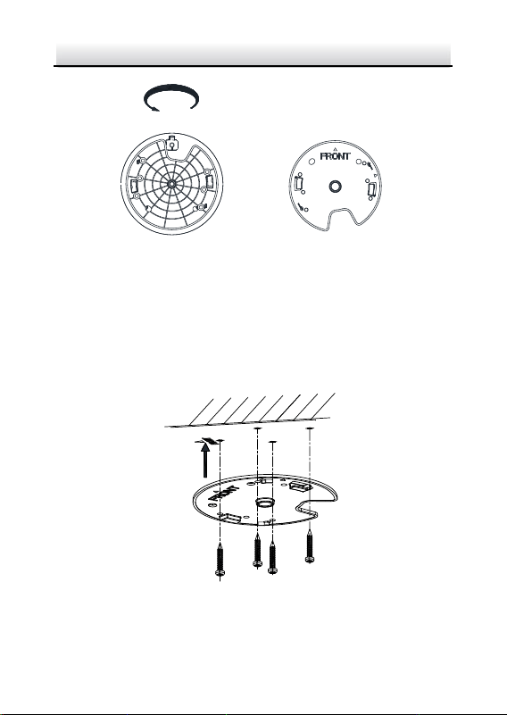
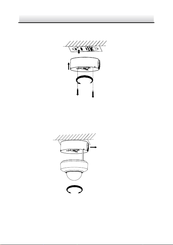
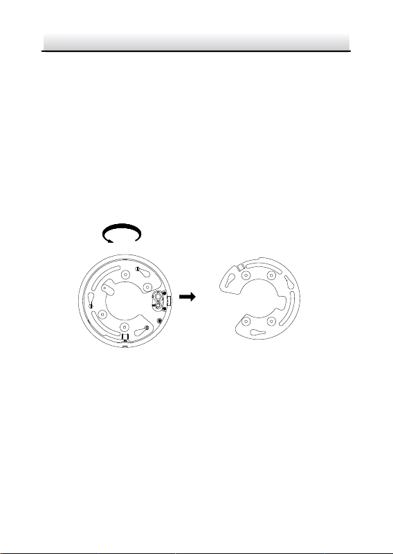
2.2 Installing DE1Axxx(I) Series PTZ Camera
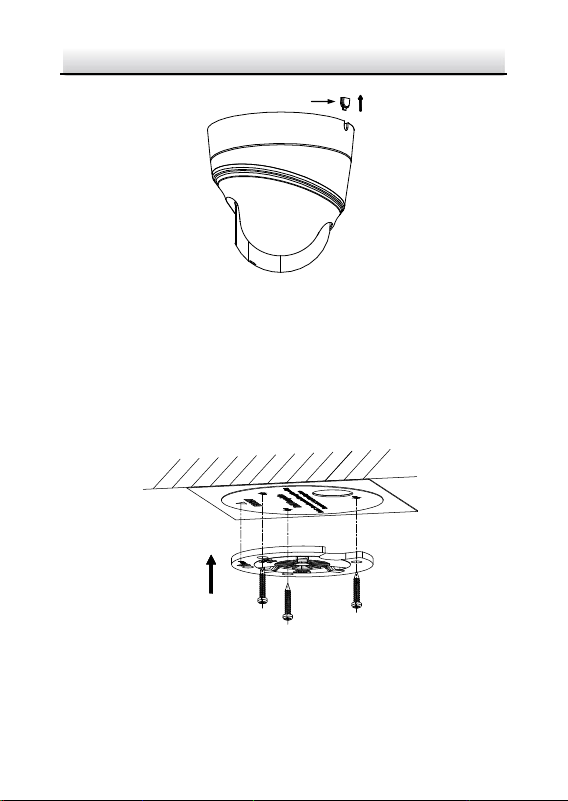
2.2.1 Ceiling Mounting
Notes:
The thickness of the ceiling shall range from 5 mm to 40 mm.
Make sure the ceiling is strong enough to withstand more than
four times the weight of the PTZ camera and its accessories.
Steps:
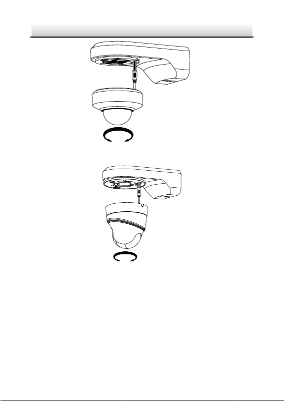
1. Rotate the installation plate anticlockwise, and remove the
installation plate, as shown in Figure 2-13.
Network PTZ Camera·Quick Start Guide
12
Installation Plate
OPEN
Figure 2-13 Remove the Installation Plate
2. Drill four screw holes in the ceiling according to the installation
plate.
3. Align the installation plate with the screw holes, and fix the
installation plate on the ceiling.
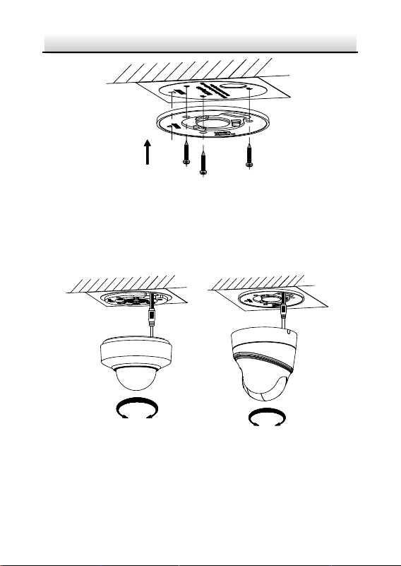
Figure 2-14 Fix the Installation Plate
Network PTZ Camera·Quick Start Guide
13
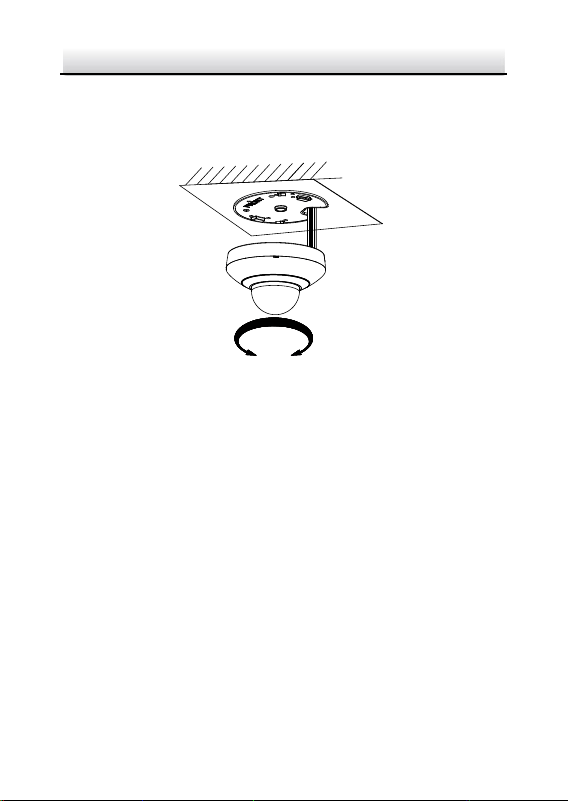
4. Route the cables from the cable hole in the installation plate.
5. Align the camera with the installation plate, and rotate the camera
clockwise to fix it, as shown in Figure 2-15.
OPEN
LOCK
Figure 2-15 Fix the Camera
2.2.2 Wall Mounting
Notes:
For cement wall, you need to use the expansion screw to fix the
bracket. The mounting hole of the expansion pipe on the wall
should align with the mounting hole on the bracket.
For wooden wall, you can just use the self-tapping screw to fix
the bracket.
Make sure that the wall is strong enough to withstand more
than eight times the weight of the PTZ camera and its
accessories.
Steps:
Network PTZ Camera·Quick Start Guide
14
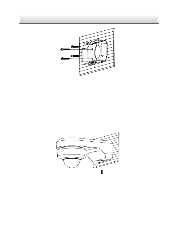
1. Remove the installation plate, and install it on the wall mounting
bracket (not supplied) with two screws.
Note:
Refer to step 1 in section 2.2.1 Ceiling Mounting to remove the
installation plate.
Figure 2-16 Install the Installation Plate
2. Loosen the fixing screw on the bracket and remove the bracket
base.
Fixing Screw
Bracket Base
Figure 2-17 Remove the Bracket Base
3. Install the bracket base on the wall with four screws.
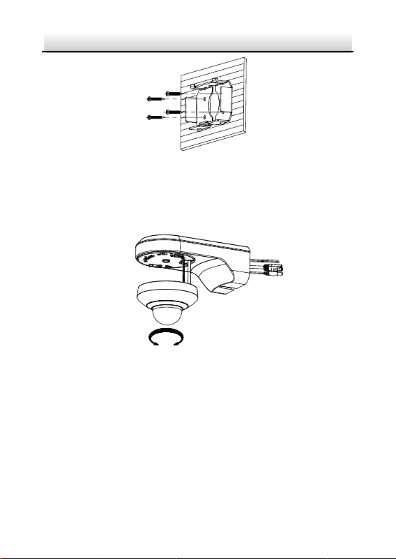
Network PTZ Camera·Quick Start Guide
15
Figure 2-18 Install the Bracket Base
4. Route the cables. Align the camera with the installation plate on
the wall mounting bracket, and rotate the camera clockwise to fix
it on the bracket.
OPEN
LOCK
Figure 2-19 Install the Camera
5. Connect the cables. Install the wall mounting bracket to the
bracket base on the wall, and fix it with the supplied screw.
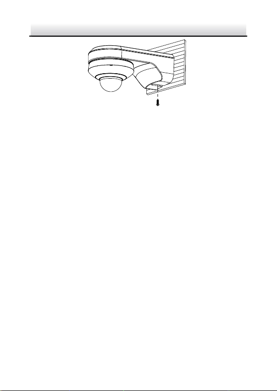
Network PTZ Camera·Quick Start Guide
16
Figure 2-20 Fix the Bracket
6. Remove the protective film after installation.
2.3 Installing DE2Axxx(I) Series PTZ Camera
Note:
The installation steps are similar to the installation steps of
DE1Axxx(I) series camera. Refer to section 2.2 Installing DE1Axxx(I)
Series PTZ Camera.
2.4 Installing DE2xxx(I) Series PTZ Camera
DE2xxx series PTZ camera supports wall mounting, ceiling mounting,
and installing with junction box. DE2xxxI Series (IR) PTZ camera
supports wall mounting and ceiling mounting.
2.4.1 Wall Mounting
Notes:
For cement wall, you need to use the expansion screw to fix the
bracket. The mounting hole of the expansion pipe on the wall
should align with the mounting hole on the bracket.
Network PTZ Camera·Quick Start Guide
17
For wooden wall, you can just use the self-tapping screw to fix
the bracket.
Make sure that the wall is strong enough to withstand more
than eight times the weight of the PTZ camera and its
accessories.
Steps:
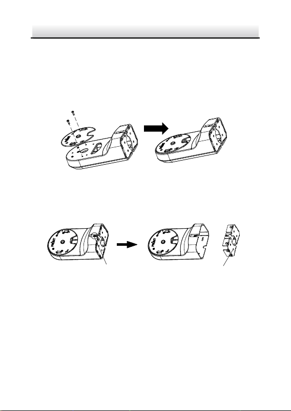
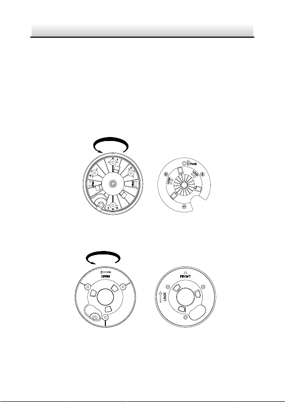
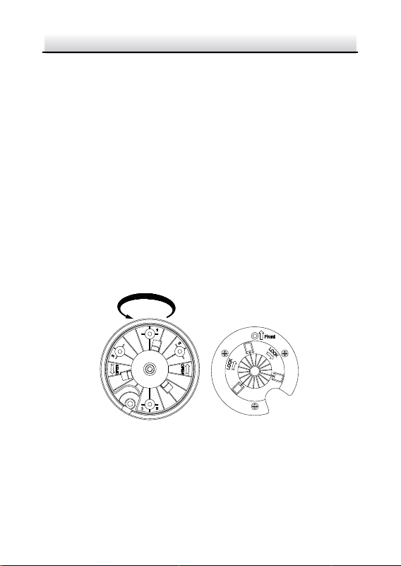
1. Rotate the base plate counterclockwise to separate it from the PTZ
camera.
Front View of Base Plate
OPEN
Base Plate on the Bottom of the Dome
Figure 2-21 Base Plate for DE2xxx Series PTZ Camera
Front View of Base PlateBase Plate on the Bottom of the Dome
OPEN
Figure 2-22 Base Plate for DE2xxxI Series (IR) PTZ Camera
Network PTZ Camera·Quick Start Guide
18
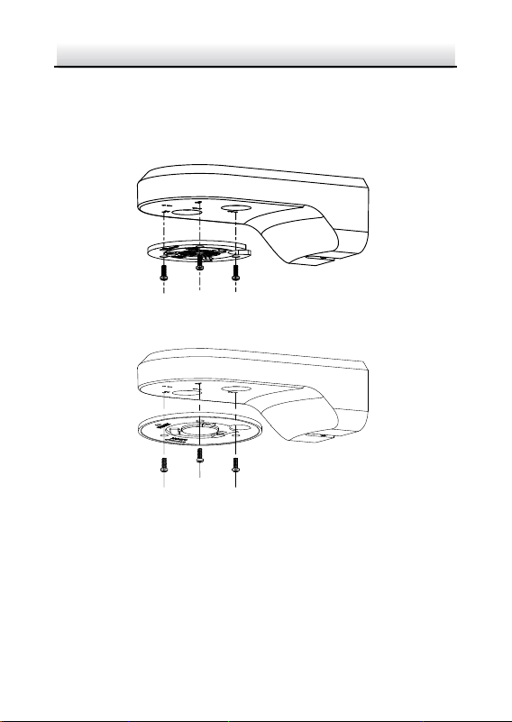
2. Align the cable hole on the base plate with the hole on the bracket
for wiring. And install the base plate to the bracket by fixing three
PM4×10 screws (supplied) to the holes marked with digit “2” on
the bracket.
Figure 2-23 For DE2xxx Series PTZ Camera
Figure 2-24 For DE2xxxI Series (IR) PTZ Camera
3. Route the cables through the cable hole.
4. Align the PTZ camera with the base plate. Rotate the PTZ camera
clockwise to the base plate, and the PTZ camera is secured with
the base plate by three locks on the plate.
Network PTZ Camera·Quick Start Guide
19
LOCKOPEN
Figure 2-25 Secure DE2xxx Series PTZ Camera
LOCK
OPEN
Figure 2-26 Secure DE2xxxI Series (IR) PTZ Camera
5. Secure the mounting base to the wall with four PA4×25 screws
(supplied).
Network PTZ Camera·Quick Start Guide
20
Figure 2-27 Install the Mounting Base
6. Install the PTZ camera to the bracket.
1). Route the cables of the PTZ camera through the wall bracket.
2). Connect the corresponding cables.
3). Hang the bracket together with the PTZ camera on the
mounting base.
4). Fix the mounting base with a PM4×10 screw.
Figure 2-28 Secure the Mounting Base
2.4.2 Ceiling Mounting
Purpose:
There are two ceiling mounting types provided for the camera, and
we take the mounting without the junction box as the example.
Network PTZ Camera·Quick Start Guide
21
Notes:
The ceiling mounting is applicable to the indoor/outdoor solid
ceiling construction. The followings are the mandatory
precondition for ceiling mounting:
The thickness of the ceiling shall range from 5 mm to 40 mm.
Make sure the ceiling is strong enough to withstand more than
four times the weight of the PTZ camera and its accessories.
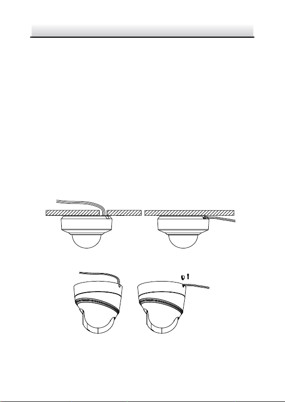
Wiring
The cables of PTZ camera can be routed either from the top or the
side of the back box, as shown in Figure 2-29 and Figure 2-30.
For the cables routed from the top of the back box, it is required to
drill a cable hole in the ceiling.
Figure 2-29 Cabling for DE2xxx Series PTZ Camera
Figure 2-30 Cabling for DE2xxxI Series (IR) PTZ Camera
Network PTZ Camera·Quick Start Guide
22
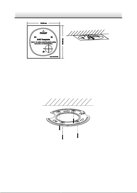
Ceiling Mounting without Junction Box
Steps:
1. Rotate the base plate counterclockwise to separate it from the PTZ
camera, as shown in Figure 2-21 and Figure 2-22.
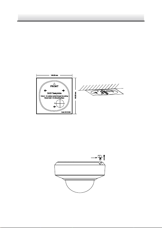
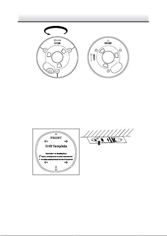
2. Attach the drill template (supplied) to the place where you want
to fix the PTZ camera, and make sure the front arrow appoints to
the monitoring area.
Figure 2-31 Attach the Drill Template
3. Drill a cable hole in the ceiling according to the circle A on the
template if you want to route the cables through the ceiling. Pull
out the cable slot cover if you want to route the cables on the
surface of the ceiling, as shown in Figure 2-32.
Cable Slot Cover
Figure 2-32 For DE2xxx Series PTZ Camera
Network PTZ Camera·Quick Start Guide
23
Cable Slot Cover
Figure 2-33 For DE2xxxI Series (IR) PTZ Camera
4. Attach the base plate to the ceiling and secure it with the supplied
three self-tapping screws by aligning with three screw holes in the
ceiling, and the front arrows on the drill template and base plate
should be aligned together as well, as shown in Figure 2-34 and
Figure 2-35.
Figure 2-34 For DE2xxx Series PTZ Camera
Network PTZ Camera·Quick Start Guide
24
Figure 2-35 For DE2xxxI Series (IR) PTZ Camera
5. Route the cables through the cable hole.
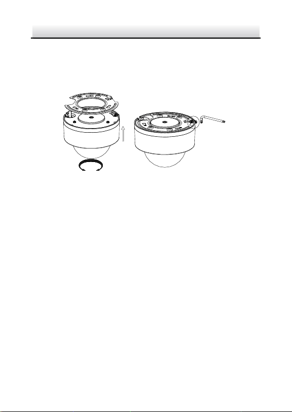
6. Align the PTZ camera with the base plate. Rotate the PTZ camera
clockwise into the base plate, and the PTZ camera is secured with
the base plate by three locks on the plate.
OPEN LOCK
LOCK
OPEN
Figure 2-36 Secure the PTZ Camera
Network PTZ Camera·Quick Start Guide
25
2.4.3 Installing with Junction Box
Notes:
The thickness of the ceiling shall range from 5 mm to 40 mm.
Make sure the ceiling is strong enough to withstand more than
four times the weight of the PTZ camera and its accessories.
Steps:
1. Rotate the base plate counterclockwise to separate it from the PTZ
camera.
Notes:
The base plate is not required when you install the PTZ
camera with junction box. Keep it properly.
The junction box is the optional accessory. Get it prepared
before installation.
Front View of Base Plate
OPEN
Base Plate on the Bottom of the Dome
Figure 2-37 For DE2xxx Series PTZ Camera
Network PTZ Camera·Quick Start Guide
26
Front View of Base PlateBase Plate on the Bottom of the Dome
OPEN
Figure 2-38 For DE2xxxI Series (IR) PTZ Camera
2. Attach the drill template (supplied) to the place where you want
to fix the PTZ camera, and make sure the front arrow appoints to
the monitoring area.
3. Insert two PM4×10 screws into the ceiling, as shown in Figure
2-39.
Figure 2-39 Attach the Drill Template
4. Attach the junction box to the ceiling and secure it by aligning the
holes with two screws and rotating the junction box according to
the direction as shown in Figure 2-40. Make sure the front arrows
Network PTZ Camera·Quick Start Guide
27
on the drill template and junction box should be aligned together
as well.
Figure 2-40 Fix the Junction Box
5. Connect the cables and route the cables clockwise through the
hooks and fix the camera and the junction box with three hooks.
Tighten it clockwise and loosen it anticlockwise.
Cable Outlet
OPEN LOCK
Figure 2-41 Fix the Camera
6. Secure the PTZ camera and remove the protective film.

Network PTZ Camera·Quick Start Guide
28
2.5 Installing DE3xxx Series PTZ Camera
DE3xxx series PTZ camera supports ceiling mounting and in-ceiling
mounting.
Note:
Wall mounting, installation with junction box, and installation with
tripod are supported for DE3xxx series PTZ camera. The
corresponding accessories shall be purchased separately.
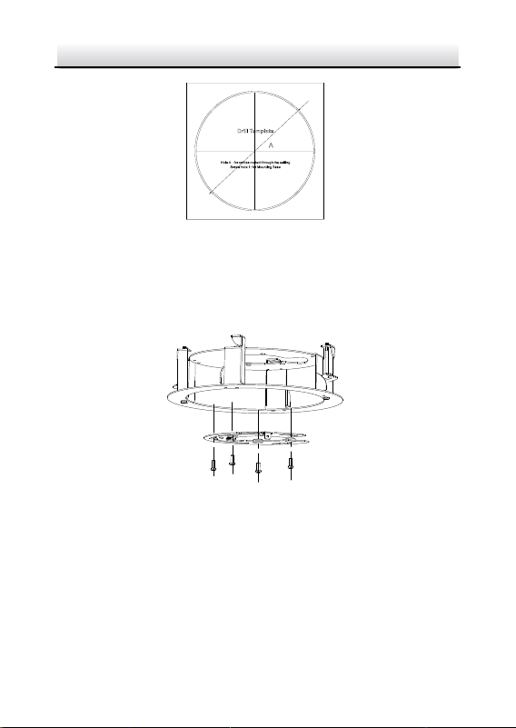
2.5.1 Ceiling Mounting
Notes:
The thickness of the ceiling shall range from 5 mm to 40 mm.
Make sure the ceiling is strong enough to withstand more than
four times the weight of the PTZ camera and its accessories.
Steps:
1. Attach the drill template (supplied) to the place where you want
to fix the PTZ camera, and make sure the front arrow appoints to
the monitoring area.
2. Drill a cable hole in the ceiling according to the circle A on the
template if you want to route the cables through the ceiling, as
shown in Figure 2-42.
Network PTZ Camera·Quick Start Guide
29
Figure 2-42 Attach the Drill Template
3. Insert the expansion screws into the ceiling. (Optional)
4. Insert four PM4×10 screws into the ceiling and fix the base plate,
as shown in Figure 2-43. Make sure the FRONT arrow of the base
plate is of the same direction as the arrow of the drill template.
Figure 2-43 Fix the Base Plate
5. Connect the cables and route the cable through the cable outlet.
Align the PTZ camera with the base plate. Rotate the PTZ camera
Network PTZ Camera·Quick Start Guide
30
clockwise into the base plate, and the PTZ camera is secured with
the base plate by three locks on the plate.
6. Fix the screws on the side with a screwdriver, as shown in Figure
2-44.
①
OPEN LOCK
②
③
Figure 2-44 Fix the Camera
7. Secure the PTZ camera and remove the protective film.
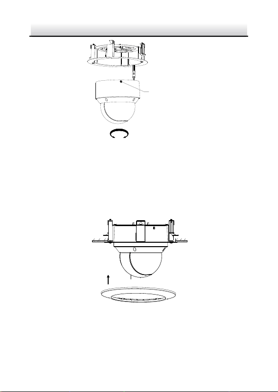
2.5.2 In-ceiling Mounting
Notes:
Reserve at least 250 mm of height for in-ceiling mounting.
The thickness of the ceiling shall range from 5 mm to 40 mm.
Make sure the ceiling is strong enough to withstand more than
four times the weight of the PTZ camera and its accessories.
Steps:
1. Attach the drill template (supplied) to the place where you want
to fix the PTZ camera, and drill a hole in the ceiling according to
the template.
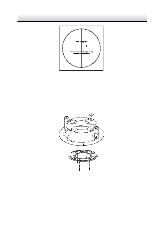
Network PTZ Camera·Quick Start Guide
31
Figure 2-45 Drill Template
2. Fix the base plate onto the in-ceiling bracket with the four screws
in the package (supplied). Make sure that the cable holes of the
base plate are aligned to the cable holes of the bracket, as shown
in Figure 2-46.
Figure 2-46 Fix the Base Plate to In-ceiling Bracket
3. Connect the cables and route the cable through the cable hole.
Network PTZ Camera·Quick Start Guide
32
4. Align the PTZ camera with the base plate. Rotate the PTZ camera
clockwise into the base plate, and the PTZ camera is secured with
the base plate by three locks on the plate.
5. Fix the screws on the side with a screwdriver, as shown in Figure
2-47.
①
OPEN LOCK
②
③
Figure 2-47 Fix the Camera
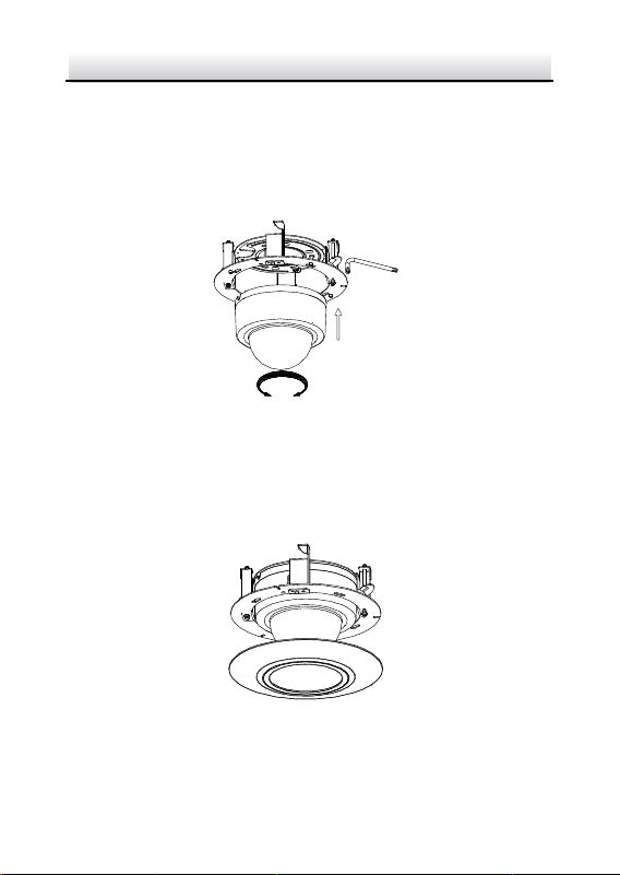
6. Fix the decorative rim with the bubble and the decorative rim will
be attached to the in-ceiling bracket automatically, as shown in
Figure 2-48.
Figure 2-48 Assemble the Decorative Rim
7. Secure the camera and remove the protective film.
Network PTZ Camera·Quick Start Guide
33
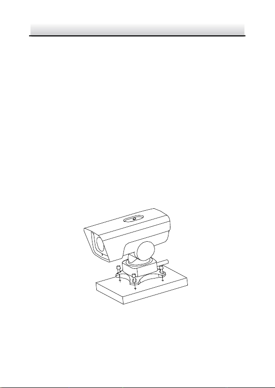
2.6 Installing DY3xxx Series PTZ Bullet Camera
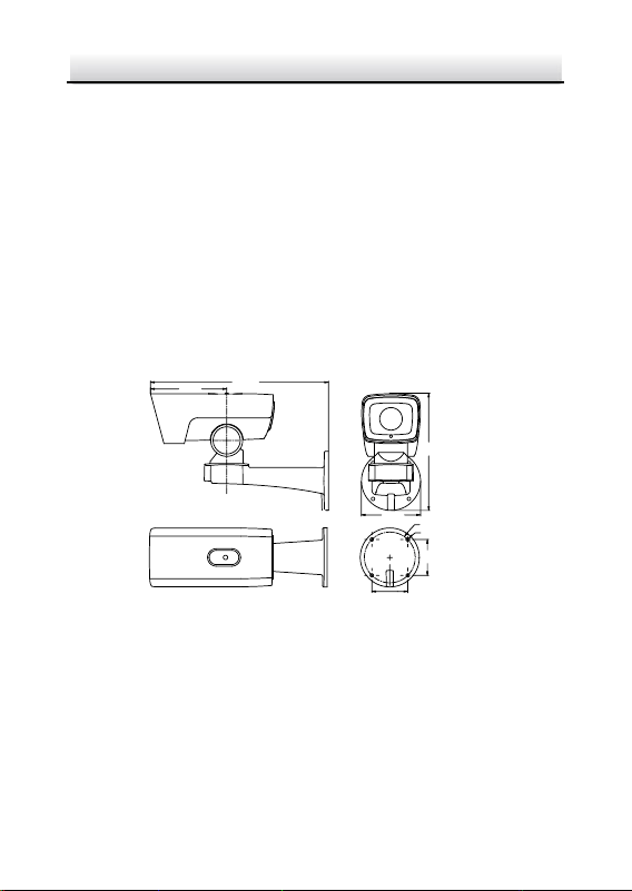
2.6.1 Dimensions of DY3xxx Series PTZ Bullet Camera
Two structures of DY3xxx Series PTZ bullet cameras are available:
wall-mounted PTZ bullet camera and base-mounted PTZ bullet
camera.
Select the proper PTZ bullet camera and the installation method
according to its working environment.
Dimensions of wall-mounted PTZ bullet camera is shown in
Figure 2-49.
367
122
157
(74.2)
(74.2)
4-φ7
φ105
Unit: mm
242
Figure 2-49 Wall-mounted PTZ Bullet Camera
Dimensions of base mounted PTZ bullet camera is shown in
Figure 2-50.
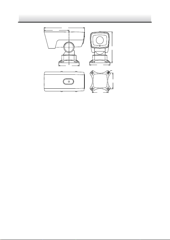
Network PTZ Camera·Quick Start Guide
34
255
129
157
129
100
100
4-φ7
Unit: mm
195
Figure 2-50 Base-mounted PTZ Bullet Camera
2.6.2 Wall Mounting
Before you start:
The wall-mounted PTZ bullet camera can be installed on cement wall
and pole mounting. The installing environment shall meet the
following conditions:
For cement wall, you need to use the expansion screw to fix the
bracket. The mounting hole of the expansion pipe on the wall
should align with the mounting hole on the bracket.
For wooden wall, you can just use the self-tapping screw to fix
the bracket.
Make sure that the wall is strong enough to withstand more
than eight times the weight of the PTZ camera and its
accessories.
Steps:
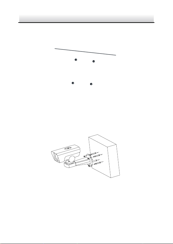
Network PTZ Camera·Quick Start Guide
35
1. Drill screw holes on the wall according to the dimensions of
wall-mounted camera and insert four M6 expansion screws into
the screw holes, as shown in Figure 2-51.
Figure 2-51 Drill Screw Holes
2. Route the cables through the camera bracket and cover the four
hex nuts with flat washers.
3. Fix the camera on the wall by knocking the expansion screws into
the wall through the bracket, as shown in Figure 2-52.
Figure 2-52 Install the Wall-mounted PTZ Bullet Camera
Note:
To install the PTZ bullet camera with the pole, you can use hexagon
socket screws instead of the expansion screws.
Network PTZ Camera·Quick Start Guide
36
2.6.3 Base Mounting
Before you start:
Base-mounted PTZ bullet camera can be installed on hard plane
structures such as cement surface.
Note:
Make sure that the plane structure is strong enough to withstand
more than eight times the weight of the PTZ camera and its
accessories.
Steps:
1. Drill screw holes on the plane surface according to the dimensions
of base-mounted camera.
2. Insert four M6 hexagon socket screws (with length of 30 mm)
through the camera bracket and the plane structure, and then
lock the screw nuts to fix the camera, as shown in Figure 2-53.
Figure 2-53 Install Base-mounted Camera
Network PTZ Camera·Quick Start Guide
37
2.7 Installing DE4AxxxI Series PTZ Camera
DE4AxxxI series (IR) PTZ camera supports ceiling mounting and
in-ceiling mounting.
Note:
Wall mounting, pendant mounting, and installation with junction box
are supported for DE4AxxxI series (IR) PTZ camera. The
corresponding accessories shall be purchased separately.
2.7.1 Ceiling Mounting
Ceiling mounting for DE4AxxxI series (IR) PTZ camera is similar to
ceiling mounting for DE2xxx series & DE2xxxI series (IR) PTZ camera.
Refer to section 2.4.2 Ceiling Mounting for details.
Note:
After DE4AxxxI series (IR) PTZ camera is installed, tighten the fixing
screw with a screwdriver as shown in Figure 2-54.
Fixing Screw
Figure 2-54 Tighten the Fixing Screw
Network PTZ Camera·Quick Start Guide
38
2.7.2 In-ceiling Mounting
Notes:
Reserve at least 250 mm of height for in-ceiling mounting.
The thickness of the ceiling shall range from 5 mm to 40 mm.
Make sure the ceiling is strong enough to withstand more than
four times the weight of the PTZ camera and its accessories
Steps:
1. Rotate the base plate counterclockwise to separate it from the PTZ
camera, as shown in Figure 2-55.
Rotate Counterclockwise
Separate the Base Plate from the
PTZ Camera
Figure 2-55 Separate the Base Plate from the PTZ camera
2. Attach the drill template (supplied) to the place where you want
to fix the PTZ camera, and drill a hole in the ceiling according to
the template.
Network PTZ Camera·Quick Start Guide
39
212
Ø
Figure 2-56 Drill Template
3. Align the cable holes of the base plate to the cable holes of the
in-ceiling bracket and then fix the base plate onto the bracket with
the four screws in the package (supplied), as shown in Figure 2-57.
Figure 2-57 Fix the Base Plate to In-ceiling Bracket
4. Connect the cables and route the cables through the cable hole.
5. Align the PTZ camera with the base plate. Rotate the PTZ camera
clockwise into the base plate, and the PTZ camera is secured with
the base plate by three locks on the plate.
6. Fix the screws on the side with a screwdriver, as shown in Figure
2-58.
Network PTZ Camera·Quick Start Guide
40
LOCK
OPEN
Fix the Screw
①
②
Figure 2-58 Fix the Camera
7. Place the camera and the bracket into the hole drilled in step 2,
and rotate the screws clockwise to fix the camera.
8. Fix the decorative rim with the bubble and the decorative rim will
be attached to the in-ceiling bracket automatically, as shown in
Figure 2-59.
①
Fix the Screw
②
Fix the Decorative Rim
Figure 2-59 Assemble the Decorative Rim
Network PTZ Camera·Quick Start Guide
41
3 Setting the PTZ Camera over the LAN
Notes:
You shall acknowledge that the use of the product with Internet
access might be under network security risks. For avoidance of
any network attacks and information leakage, strengthen your
own protection. If the product does not work properly, contact
with your dealer or the nearest service center.
To ensure network security of the network PTZ camera, we
recommend you to have the camera assessed and maintained
termly. You can contact us if you need such service.
3.1 Wiring
To view and configure the network PTZ camera via LAN (Local Area
Network), you need to connect the network PTZ camera in the same
subnet with your PC. Then, install the SADP or client software to
search and change the IP address of network PTZ camera.
Connect the camera to network according to the following figures.
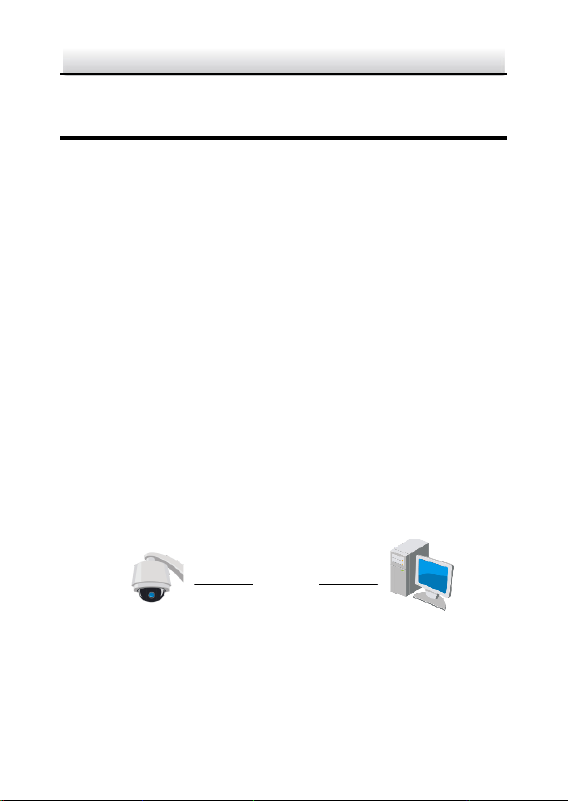
Network Cable
Network PTZ Camera
Computer
Figure 3-1 Connecting Directly
Network PTZ Camera·Quick Start Guide
42
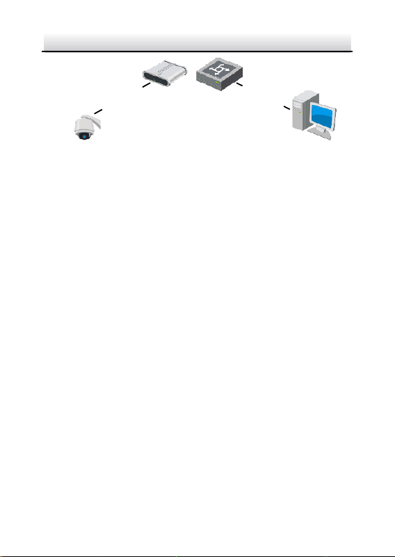
网络交换机
Network Cable
Network Cable
or
Network PTZ Camera
Computer
Figure 3-2 Connecting via a Switch or a Router
3.2 Activating the Camera
Purpose:
You are required to activate the camera first by setting a strong
password for it before you can use the camera.
Activation via web browser, activation via SADP, and activation via
client software are supported. We will take activation via SADP
software and activation via web browser as examples to introduce
the camera activation.
Note:
For the details of activation via client software, refer to the user
manual of the network camera.
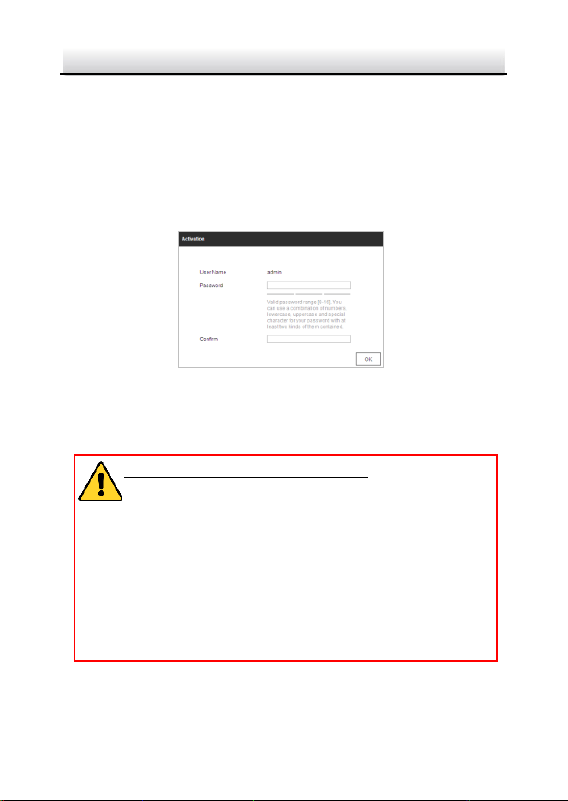
3.2.1 Activation via Web Browser
Steps:
1. Power on the camera. Connect the camera to your computer or
the switch/router which your computer connects to.
2. Input the IP address into the address bar of the web browser, and
enter the activation interface.
Network PTZ Camera·Quick Start Guide
43
Notes:
The default IP address of the camera is 192.168.1.64.
The computer and the camera should belong to the same
subnet.
For the camera enables the DHCP by default, you need to use
the SADP software to search the IP address.
Figure 3-3 Activation Interface (Web)
3. Create a password and input the password into the password
field.
STRONG PASSWORD RECOMMENDED– We highly
recommend you create a strong password of your own
choosing (using a minimum of 8 characters, including at
least three of the following categories: upper case letters,
lower case letters, numbers, and special characters) in
order to increase the security of your product. And we
recommend you reset your password regularly, especially
in the high security system, resetting the password
monthly or weekly can better protect your product.
4. Confirm the password.
5. Click OK to activate the camera and enter the live view interface.
Network PTZ Camera·Quick Start Guide
44
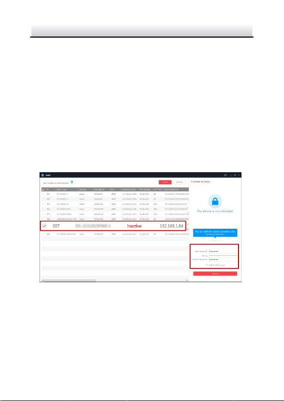
3.2.2 Activation via SADP Software
SADP software is used for detecting the online device, activating the
device, and resetting the password.
Get the SADP software from the supplied disk or the official website,
and install the SADP according to the prompts.
Follow the steps to activate the camera.
Steps:
1. Run the SADP software to search the online devices.
2. Check the device status from the device list, and select an inactive
device.
Select inactive device.
Input and confirm
password.
Figure 3-4 SADP Interface
Note:
The SADP software supports activating the camera in batch. Refer
to the user manual of SADP software for details.
Network PTZ Camera·Quick Start Guide
45
3. Create a password and input the password in the password field,
and confirm the password.
STRONG PASSWORD RECOMMENDED– We highly
recommend you create a strong password of your own
choosing (using a minimum of 8 characters, including at
least three of the following categories: upper case letters,
lower case letters, numbers, and special characters) in
order to increase the security of your product. And we
recommend you reset your password regularly, especially
in the high security system, resetting the password
monthly or weekly can better protect your product.
Note:
You can enable the Hik-Connect service for the device during
activation. Refer to section 5.1 Enable Hik-Connect Service on
Camera.
4. Click Activate to save the password.
Note:
You can check whether the activation is completed on the popup
window. If activation failed, make sure that the password meets
the requirement and try again.
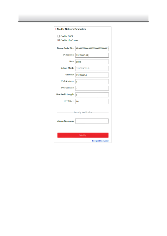
3.3 Modifying the IP Address
Purpose:
To view and configure the camera via LAN (Local Area Network), you
need to connect the network camera in the same subnet with your
PC.

Network PTZ Camera·Quick Start Guide
46
Use the SADP software or client software to search and change the
IP address of the device. We take modifying the IP Address via SADP
software as an example to introduce the IP address modification.
Note:
For IP address modification via client software, refer to the user
manual of client software.
Steps:
1. Run the SADP software.
2. Select an active device.
3. Change the device IP address to the same subnet with your
computer by either modifying the IP address manually or checking
the Enable DHCP checkbox.
Network PTZ Camera·Quick Start Guide
47
Figure 3-5 Modify the IP Address
Note:
You can enable the Hik-Connect service for the device during
activation. Refer to section 5.1 Enable Hik-Connect Service on
Camera.
4. Input the admin password and click Modify to activate your IP
address modification. The batch IP address modification is
supported by SADP. Refer to the user manual of SADP for details.

Network PTZ Camera·Quick Start Guide
48
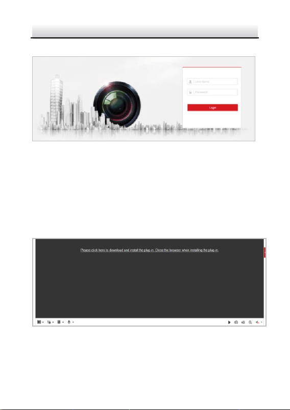
4 Accessing via Web Browser
System Requirement:
Operating System: Microsoft Windows XP SP1 and above
version/Vista/Win7/Server 2003/Server 2008 32bits
CPU: Intel Pentium IV 3.0 GHz or higher
RAM: 1G or higher
Display: 1024 × 768 resolution or higher
Web Browser: Internet Explorer 8.0 and above version, Apple Safari
5.02 and above version, Mozilla Firefox 5 and above version and
Google Chrome 18 and above version
Steps:
1. Open the web browser.
2. In the browser address bar, input the IP address of the network
PTZ camera, and enter the login interface.
Note:
The default IP address is 192.168.1.64. You are recommended to
change the IP address to the same subnet with your computer.
3. Input the user name and password.
The admin user should configure the device accounts and
user/operator permissions properly. Delete the unnecessary
accounts and user/operator permissions.
Note:
The device IP address gets locked if the admin user performs 7
failed password attempts (5 attempts for the user/operator).
Network PTZ Camera·Quick Start Guide
49
4. Click Login.
Figure 4-1 Login Interface
5. Install the plug-in before viewing the live video and managing the
network PTZ camera. Follow the installation prompts to install the
plug-in.
Note:
You may have to close the web browser to finish the installation of
the plug-in.
Figure 4-2 Download Plug-in
6. Reopen the web browser after the installation of the plug-in and
repeat the above steps 2-4 to login.

Network PTZ Camera·Quick Start Guide
50
Note:
For detailed instructions of further configuration, refer to the user
manual of the network camera.

Network PTZ Camera·Quick Start Guide
51
5 Operating via Hik-Connect App
Purpose:
Hik-Connect is an application for mobile devices. With the App, you
can view live image of the camera, receive alarm notification and so
on.
Note:
Hik-Connect service is not supported by certain camera models.
5.1 Enable Hik-Connect Service on Camera
Purpose:
Hik-Connect service should be enabled on your camera before using
the service.
You can enable the service through SADP software or web browser.
5.1.1 Enable Hik-Connect Service via SADP Software
Steps:
1. Check the Enable Hik-Connect checkbox on:
1). "Activate the Device" page during camera activation, refer to
section 3.2.2 Activation via SADP Software.
2). Or "Modify Network Parameters" page during modifying IP
address, refer to section 3.3 Modifying the IP Address.
2. Create a verification code or change the verification code.
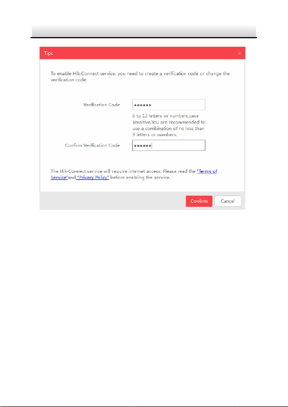
Network PTZ Camera·Quick Start Guide
52
Figure 5-1 Verification Code Setting (SADP)
Note:
The verification code is required when you add the camera to
Hik-Connect app.
3. Click and read "Terms of Service" and "Privacy Policy".
4. Confirm the settings.
5.1.2 Enable Hik-Connect Service via Web Browser
Before you start:
You need to activate the camera before enabling the service. Refer to
section 3.2 Activating the Camera.

Network PTZ Camera·Quick Start Guide
53
Steps:
1. Access the camera via web browser. Refer to section 4 Accessing
via Web Browser.
2. Enter platform access configuration interface:
Configuration > Network > Advanced Settings > Platform Access
Figure 5-2 Platform Access Configuration (Web)
3. Select Platform Access Mode as Hik-Connect.
4. Check the Enable checkbox.
5. Click and read "Terms of Service" and "Privacy Policy" in pop-up
window.
6. Create a verification code or change the verification code for the
camera.
Note:
The verification code is required when you add the camera to
Hik-Connect app.
7. Save the settings.
Network PTZ Camera·Quick Start Guide
54
5.2 Hik-Connect Setup
Steps:
1. Download and install the Hik-Connect app by searching
“Hik-Connect” in App Store or Google Play
TM
.
2. Launch the app and register for a Hik-Connect user account.
3. Log in Hik-Connect app after registration.
5.3 Adding Camera to Hik-Connect
Before you start:
You need to enable the Hik-Connect service on camera before adding
it to your Hik-Connect account. Refer to section 5.1 Enable
Hik-Connect Service on Camera.
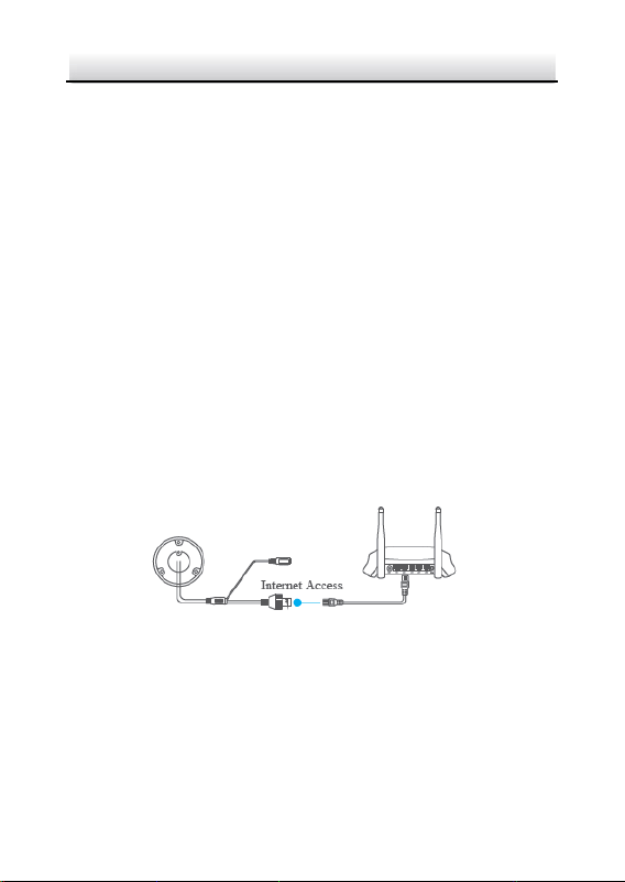
Steps:
1. Use a network cable to connect the camera with a router if the
camera does not support Wi-Fi.
Figure 5-3 Connect a Router
Note:
After the camera connects to the network, wait one minute before
any operation on the camera using Hik-Connect app.
2. In the Hik-Connect app, tap “+” on the upper-right corner and
then scan the QR code of the camera to add the camera.
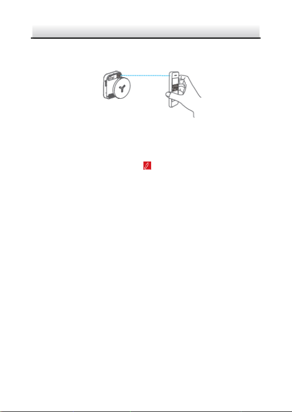
Network PTZ Camera·Quick Start Guide
55
You can find the QR code on the camera or on the cover of the
quick start guide of the camera in the package.
Figure 5-4 Scan QR Code
Note:
If the QR code is missing or too blur to be recognized, you can also
add the camera by tapping the icon and inputting the
camera's serial number.
3. Input the verification code of your camera.
Notes:
The required verification code is the code you create or
change when you enabling Hik-Connect service on camera.
If you forget the verification code, you can check the current
verification code on Platform Access configuration page via
web browser.
4. Follow the prompts to set the network connection and add the
camera to your Hik-Connect account.
Note:
For detailed information, refer to the user manual of the
Hik-Connect app.

Network PTZ Camera·Quick Start Guide
56
5.4 Initializing the Memory Card
Check the memory card status by tapping on the Storage Status in
the Device Settings interface.
If the memory card status displays as Uninitialized, tap to initialize it.
The status will then change to Normal. You can then start recording
any event triggered video in the camera such as motion detection.

Network PTZ Camera·Quick Start Guide
57
UD09613B-A
