Operating Instructions
Included Installation Instructions
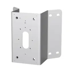
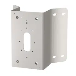
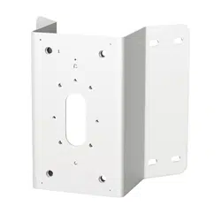
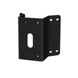
Corner Mount Bracket
Model No.
WV-QCN500
© i-PRO Co., Ltd. 2022
• Before attempting to connect or install this product, please read these instructions carefully and
save this manual for future use.
• The external appearance and other parts shown in this manual may differ from the actual product
within the scope that will not interfere with normal use due to improvement of the product.
i-PRO Co., Ltd. assumes no responsibility for injuries or property damage
resulting from failures arising out of improper installation or operation
inconsistent with this documentation.
Do not hang down from this product or use this product as a pedestal.
Failure to observe this may cause injury or accidents.
Do not use this product except with suitable cameras or brackets
Failure to observe this may cause a drop resulting in injury or accidents.
Refer installation work to the dealer.
Installation work requires technique and experiences. Failure to observe this may cause fire, electric
shock, injury, or damage to the product.
Be sure to consult the dealer.
Install the product securely on a wall or a ceiling in accordance with the
installation instructions.
Failure to observe this may cause injury or accidents..
Do not rub the edges of metal parts with your hand.
Strong rubbing may cause injury.
When using this product, also read the “Precautions” described in the operating
instructions for the camera to be attached.
In order to prevent injury, the product must be securely mounted to the wall
(corner) according to Operating Instructions.
Installation area for this product.
• Please consider the influence of vibration and wind at the installation site and mount the bracket
onto the wall with appropriate strength.
Installable corner Corner part of a vertical and right-angle wall
• Do not mount the product on a plaster board or a wooden section because they are too weak.
If the product is unavoidably mounted on such a section, the section shall be sufficiently reinforced.
• After the bracket is mounted, please verify the following content once a year. In the event of
abnormality, please inform the dealer.
· Do not allow any slanting, distortion or offset in installation.
· Bracket should not have any serious rust or damage.
• Please refer to our support website (https://i-pro.com/global/en/surveillance/training_support/
support/technical_information <Control No.:C0507>) for installation information of the bracket.
About the installation methods.
• The bracket is specifically designed for installation onto a corner of the wall.
• Prepare mounting screws (M8, locally procured) or anchors (8 pcs.) to be mounted on a wall
separately.
• Select screws according to the material of the location that the bracket will be mounted to.
Minimum pull-out strength: 823 N {185 lbf} (per 1 pc.)
• After the installation is finished, please check if there are slackness or shaking of screws and
raising of mount bracket. In the event of abnormality, please tighten again.
Check before the installation.
Once the bracket is installed with a deformed mount bracket and/or damaged part, it could
potentially fall. Before the installation, please make sure to check the appearance of the bracket.
Caution:
• Before attempting to connect or operate
this product, please read these
instructions carefully.
Notice:
• This product is not suitable for use in locations
where children are likely to be present.
• Do not install this product in locations where
ordinary persons can easily reach.
• For information about screws and brackets
required for installation, refer to the
corresponding section of this document.
Precautions
Precautions for installation
Installations
Be sure to read "Precautions" and "Precautions for installation" before installation.
Refer to the operating instructions of the camera for details on the camera installation
(including the camera mounting, cable connection and adjustment).
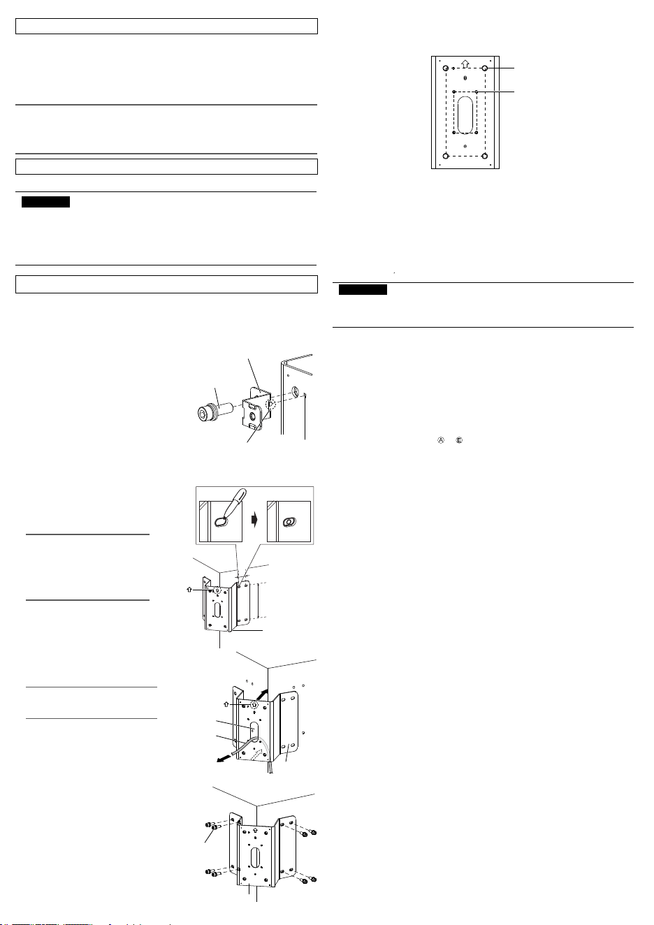
Before mounting the camera, attach the safety
wire fixing bracket (accessory) to this product.
• Use one M10 × 30 mm {1-3/16 inches}
hexagon screw (accessory) to install the
safety wire fixing bracket (accessory) on
the top left corner of this product.
(Recommended tightening torque:
10.8 N·m {7.97 lbf·ft})
Locating hole
Prominence of safety
wire fixing bracket
M10 × 30 mm {1-3/16 inches}
hexagon screw (accessory)
Safety wire fixing bracket
(accessory)
Size: 180 mm (H) × 80 mm (W)
{7-3/32 inches (H) × 3-5/32 inches (W)}
M10 screw hole (4 places)
Size: 83.5 mm (H) × 46 mm (W)
{3-9/32 inches (H) × 1-13/16 inches (W)}
M4 screw hole (4 places)
Size for installation side
Size illustration for installing part of WV-QCN500
When the camera is directly attached to this product and the camera equipped with a
safety wire.
<Mountable models>
You can attach the camera directly to this product, or attach the camera by using the following bracket
combination.
- WV-QWL501 (Wall Mount Bracket)
- WV-QSR501 (Mount Bracket)
- WV-QWL500 (Wall Mount Bracket)
- WV-QJB500 (Adapter Box)
For the latest information about the mountable models, refer to our support website
(https://i-pro.com/global/en/surveillance/training_support/support/technical_information
<Control No.:C0501 C0502>).
IMPORTANT:
• Only one bracket and camera can be installed with this product. Do not install any
bracket or camera which is not described in the manual (this document) or our
support website.
Please choose one appropriate way from the following five installation methods according to the
camera to be installed. For the cables connected to camera, please refer to the operating instructions
of camera.
When mounting an outdoor dome type camera
Ⓐ
Mount the camera by using this product with WV-QWL501 and WV-QSR501.
Ⓑ
Mount the camera by using this product and WV-QWL500.
Ⓒ
Mount the camera by using this product with WV-QWL500 and WV-QJB500.
When mounting an outdoor box type camera
Ⓓ
Directly mount the camera to this product.
Ⓔ
Mount the camera by using this product and WV-QJB500.
As for the mounting steps from to , refer to the back side of this document and the
operating instructions of each bracket and camera.
avs0520-3122
Printed in China
Preface
This product is designed to be used to install a mount bracket for camera to an external corner of
building.
For the latest information about the mountable models, refer to our support website
(https://i-pro.com/global/en/surveillance/training_support/support/technical_information
<Control No.:C0501>).
The model number is abbreviated in some descriptions in this manual.
Ambient operating temperature: –50 °C to +60 °C {–58 °F to 140 °F}
Dimensions: 230 mm (L) × 246 mm (W) × 155 mm (H)
{9-1/16 inches (L) × 9-11/16 inches (H) × 6-3/32 inches (H)}
Mass: Approx. 1.3 k
g
{2.87 lbs}
Finish: Aluminum plate i-PRO White /black
Stainless steel plate
Specifications
Screw tightening.
• Make sure to tighten the screws (accessory) that fix camera or mount bracket onto this product.
• Do not use an impact driver. Use of an impact driver may damage the screws or cause tightening
excessively.
• When a screw is tightened, make the screw at a right angle to the surface. After tightening the
screws or bolts, perform checks to ensure that the tightening is sufficient enough so that there is
no movement or looseness.
Make sure to remove this product if it will no longer be used.
https://www.i-pro.com/
"<Control No.: C****>" used in these documents should be used to search for information
on our technical information website (https://i-pro.com/global/en/surveillance/training-
support/support/technical-information) and will guide you to the right information.
Standard accessories
Fixing screws (M8) or anchors ................................................................................................... 8 pcs.
Other items that are needed (not included)
Operating Instructions (this document) .........................................................................................1 pc.
Use the following accessories as the installation requires (use of all accessories together will likely not
be necessary):
Safety wire fixing bracket ............................................................................................................. 1 pc.
M10 × 30 mm {1-3/16 inches} hexagon screws ........................................................................ 5 pcs.
M6 × 16 mm {5/8 inches} hexagon screws ................................................................................ 2 pcs.
M4 × 20 mm {25/32 inches} hexagon screws ............................................................................ 5 pcs.
Note:
• One spare is provided for each type of screw.
• Each 8 mm {5/16 inches}, 5 mm {3/16 inches} or 3 mm {1/8 inches} hexagon wrench (locally
procured) is needed when M10, M6 or M4 hexagon screw is used.
(In this manual, hexagon socket head cap screw is described as hexagon screw.)
①
Place this product to the corner to be installed,
and marked the position of eight screw holes.
②
According to the type of screw (M8, locally
procured), drill eight holes at the marked
position.
Note:
• The corner must enough solid to
support the products installed on it.
• Please confirm the installation
height after considering the height
of installing camera onto this
product.
WV-QCN500
(This product)
③
Pass the cable to be connected with camera through the cable
access hole of this product and pull out an adequate length as
needed for the camera.
Note:
• Please make sure the arrow on the
corner mount bracket is upward.
Cable
Cable access hole
④
Use fixing screws (8 pcs.) (M8: locally procured) to install
this product onto the corner.
Minimum pull-out strength: 823 N {185 lbf} (per 1 pc.)
WV-QCN500
(This product)
Fixing screw (8 pcs.)
(M8: locally procured)
Upper mark:
Upper mark:
WV-QCN500
(This product)
Install the mount bracket onto an external corner of building.
Install camera or mount bracket for camera to corner mount bracket
180 mm
{7-3/32 inches}
40 mm {1-9/16 inches}
• This value indicates the minimum pull-out strength required value per screw. For information
about the minimum pull-out strength, refer to our support website
(https://i-pro.com/global/en/surveillance/training_support/support/technical_information
<Control No.: C0120>).
• Select screws according to the material of the location that the camera will be mounted to. In
this case, wood screws and nails should not be used.
IMPORTANT:
Operating Instructions
Included Installation Instructions
Corner Mount Bracket
Model No.
WV-QCN500
© i-PRO Co., Ltd. 2022
• Before attempting to connect or install this product, please read these instructions carefully and
save this manual for future use.
• The external appearance and other parts shown in this manual may differ from the actual product
within the scope that will not interfere with normal use due to improvement of the product.
i-PRO Co., Ltd. assumes no responsibility for injuries or property damage
resulting from failures arising out of improper installation or operation
inconsistent with this documentation.
Do not hang down from this product or use this product as a pedestal.
Failure to observe this may cause injury or accidents.
Do not use this product except with suitable cameras or brackets
Failure to observe this may cause a drop resulting in injury or accidents.
Refer installation work to the dealer.
Installation work requires technique and experiences. Failure to observe this may cause fire, electric
shock, injury, or damage to the product.
Be sure to consult the dealer.
Install the product securely on a wall or a ceiling in accordance with the
installation instructions.
Failure to observe this may cause injury or accidents..
Do not rub the edges of metal parts with your hand.
Strong rubbing may cause injury.
When using this product, also read the “Precautions” described in the operating
instructions for the camera to be attached.
In order to prevent injury, the product must be securely mounted to the wall
(corner) according to Operating Instructions.
Installation area for this product.
• Please consider the influence of vibration and wind at the installation site and mount the bracket
onto the wall with appropriate strength.
Installable corner Corner part of a vertical and right-angle wall
• Do not mount the product on a plaster board or a wooden section because they are too weak.
If the product is unavoidably mounted on such a section, the section shall be sufficiently reinforced.
• After the bracket is mounted, please verify the following content once a year. In the event of
abnormality, please inform the dealer.
· Do not allow any slanting, distortion or offset in installation.
· Bracket should not have any serious rust or damage.
• Please refer to our support website (https://i-pro.com/global/en/surveillance/training_support/
support/technical_information <Control No.:C0507>) for installation information of the bracket.
About the installation methods.
• The bracket is specifically designed for installation onto a corner of the wall.
• Prepare mounting screws (M8, locally procured) or anchors (8 pcs.) to be mounted on a wall
separately.
• Select screws according to the material of the location that the bracket will be mounted to.
Minimum pull-out strength: 823 N {185 lbf} (per 1 pc.)
• After the installation is finished, please check if there are slackness or shaking of screws and
raising of mount bracket. In the event of abnormality, please tighten again.
Check before the installation.
Once the bracket is installed with a deformed mount bracket and/or damaged part, it could
potentially fall. Before the installation, please make sure to check the appearance of the bracket.
Caution:
• Before attempting to connect or operate
this product, please read these
instructions carefully.
Notice:
• This product is not suitable for use in locations
where children are likely to be present.
• Do not install this product in locations where
ordinary persons can easily reach.
• For information about screws and brackets
required for installation, refer to the
corresponding section of this document.
Precautions
Precautions for installation
Installations
Be sure to read "Precautions" and "Precautions for installation" before installation.
Refer to the operating instructions of the camera for details on the camera installation
(including the camera mounting, cable connection and adjustment).
Before mounting the camera, attach the safety
wire fixing bracket (accessory) to this product.
• Use one M10 × 30 mm {1-3/16 inches}
hexagon screw (accessory) to install the
safety wire fixing bracket (accessory) on
the top left corner of this product.
(Recommended tightening torque:
10.8 N·m {7.97 lbf·ft})
Locating hole
Prominence of safety
wire fixing bracket
M10 × 30 mm {1-3/16 inches}
hexagon screw (accessory)
Safety wire fixing bracket
(accessory)
Size: 180 mm (H) × 80 mm (W)
{7-3/32 inches (H) × 3-5/32 inches (W)}
M10 screw hole (4 places)
Size: 83.5 mm (H) × 46 mm (W)
{3-9/32 inches (H) × 1-13/16 inches (W)}
M4 screw hole (4 places)
Size for installation side
Size illustration for installing part of WV-QCN500
When the camera is directly attached to this product and the camera equipped with a
safety wire.
<Mountable models>
You can attach the camera directly to this product, or attach the camera by using the following bracket
combination.
- WV-QWL501 (Wall Mount Bracket)
- WV-QSR501 (Mount Bracket)
- WV-QWL500 (Wall Mount Bracket)
- WV-QJB500 (Adapter Box)
For the latest information about the mountable models, refer to our support website
(https://i-pro.com/global/en/surveillance/training_support/support/technical_information
<Control No.:C0501 C0502>).
IMPORTANT:
• Only one bracket and camera can be installed with this product. Do not install any
bracket or camera which is not described in the manual (this document) or our
support website.
Please choose one appropriate way from the following five installation methods according to the
camera to be installed. For the cables connected to camera, please refer to the operating instructions
of camera.
When mounting an outdoor dome type camera
Ⓐ
Mount the camera by using this product with WV-QWL501 and WV-QSR501.
Ⓑ
Mount the camera by using this product and WV-QWL500.
Ⓒ
Mount the camera by using this product with WV-QWL500 and WV-QJB500.
When mounting an outdoor box type camera
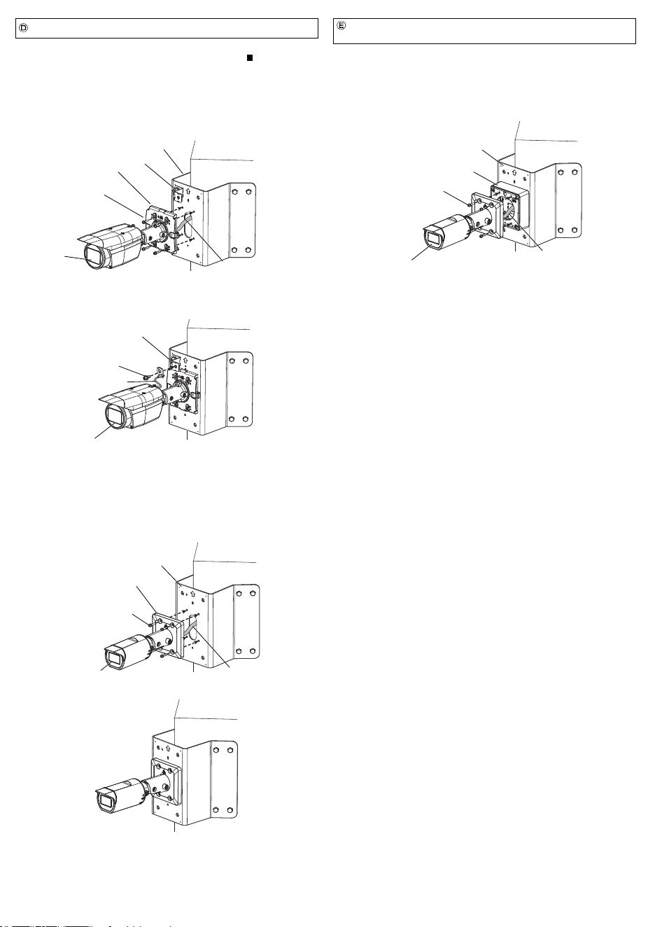
Ⓓ
Directly mount the camera to this product.
Ⓔ
Mount the camera by using this product and WV-QJB500.
As for the mounting steps from to , refer to the back side of this document and the
operating instructions of each bracket and camera.
avs0520-3122
Printed in China
Preface
This product is designed to be used to install a mount bracket for camera to an external corner of
building.
For the latest information about the mountable models, refer to our support website
(https://i-pro.com/global/en/surveillance/training_support/support/technical_information
<Control No.:C0501>).
The model number is abbreviated in some descriptions in this manual.
Ambient operating temperature: –50 °C to +60 °C {–58 °F to 140 °F}
Dimensions: 230 mm (L) × 246 mm (W) × 155 mm (H)
{9-1/16 inches (L) × 9-11/16 inches (H) × 6-3/32 inches (H)}
Mass: Approx. 1.3 k
g
{2.87 lbs}
Finish: Aluminum plate i-PRO White /black
Stainless steel plate
Specifications
Screw tightening.
• Make sure to tighten the screws (accessory) that fix camera or mount bracket onto this product.
• Do not use an impact driver. Use of an impact driver may damage the screws or cause tightening
excessively.
• When a screw is tightened, make the screw at a right angle to the surface. After tightening the
screws or bolts, perform checks to ensure that the tightening is sufficient enough so that there is
no movement or looseness.
Make sure to remove this product if it will no longer be used.
https://www.i-pro.com/
"<Control No.: C****>" used in these documents should be used to search for information
on our technical information website (https://i-pro.com/global/en/surveillance/training-
support/support/technical-information) and will guide you to the right information.
Standard accessories
Fixing screws (M8) or anchors ................................................................................................... 8 pcs.
Other items that are needed (not included)
Operating Instructions (this document) .........................................................................................1 pc.
Use the following accessories as the installation requires (use of all accessories together will likely not
be necessary):
Safety wire fixing bracket ............................................................................................................. 1 pc.
M10 × 30 mm {1-3/16 inches} hexagon screws ........................................................................ 5 pcs.
M6 × 16 mm {5/8 inches} hexagon screws ................................................................................ 2 pcs.
M4 × 20 mm {25/32 inches} hexagon screws ............................................................................ 5 pcs.
Note:
• One spare is provided for each type of screw.
• Each 8 mm {5/16 inches}, 5 mm {3/16 inches} or 3 mm {1/8 inches} hexagon wrench (locally
procured) is needed when M10, M6 or M4 hexagon screw is used.
(In this manual, hexagon socket head cap screw is described as hexagon screw.)
①
Place this product to the corner to be installed,
and marked the position of eight screw holes.
②
According to the type of screw (M8, locally
procured), drill eight holes at the marked
position.
Note:
• The corner must enough solid to
support the products installed on it.
• Please confirm the installation
height after considering the height
of installing camera onto this
product.
WV-QCN500
(This product)
③
Pass the cable to be connected with camera through the cable
access hole of this product and pull out an adequate length as
needed for the camera.
Note:
• Please make sure the arrow on the
corner mount bracket is upward.
Cable
Cable access hole
④
Use fixing screws (8 pcs.) (M8: locally procured) to install
this product onto the corner.
Minimum pull-out strength: 823 N {185 lbf} (per 1 pc.)
WV-QCN500
(This product)
Fixing screw (8 pcs.)
(M8: locally procured)
Upper mark:
Upper mark:
WV-QCN500
(This product)
Install the mount bracket onto an external corner of building.
Install camera or mount bracket for camera to corner mount bracket
180 mm
{7-3/32 inches}
40 mm {1-9/16 inches}
• This value indicates the minimum pull-out strength required value per screw. For information
about the minimum pull-out strength, refer to our support website
(https://i-pro.com/global/en/surveillance/training_support/support/technical_information
<Control No.: C0120>).
• Select screws according to the material of the location that the camera will be mounted to. In
this case, wood screws and nails should not be used.
IMPORTANT:
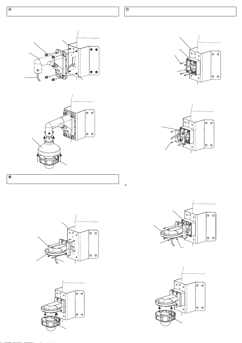
①
Pass the cable coming from this product through the base bracket of WV-QJB500 and
fix the base bracket of WV-QJB500 by using M4×20 mm {25/32 inches} hexagon screws
(4 pcs.) (accessory).
(Recommended tightening torque: 1.37 N·m {1.01 lbf·ft})
Cable
M4×20 mm {25/32 inches} hexagon screw
(4 pcs.) (accessory)
WV-QJB500
(Other optional accessory)
②
Install the attachment plate of WV-QJB500 as described in the operating instructions of
WV-QJB500.
(Recommended tightening torque: 1.37 N·m {1.01 lbf·ft})
M4 attachment fixing screw (4pcs.)
(WV-QJB500 accessory)
Install the camera by using this product with Wall Mount Bracket
(WV-QWL500) and Adapter Box (WV-QJB500).
<In case of the camera with a square shaped camera mount bracket and a safety wire>
For details about how to install the safety wire fixing bracket, refer to " When the camera
is directly attached to this product and the camera equipped with a safety wire."
①
Connect the cable coming from this product to the camera. For details about the
connection and waterproofing, refer to the operating instructions of the camera.
②
Align the four installation holes of camera mount bracket with the M4 screw holes (4
places) of this product, and fix the camera with M4 × 20 mm {25/32 inches} hexagon
screws (4 pcs.) (accessory).
(Recommended tightening torque: 1.37 N·m {1.01 lbf·ft})
For the fixing of camera and installation of camera mount bracket cover (accessory
attached with the camera), please refer to the operating instructions of the camera.
③
Use one M6 × 16 mm {5/8 inches} hexagon screw (accessory) to fix the safety wire of
the camera onto the safety wire fixing bracket (accessory).
(Recommended tightening torque: 2.45 N·m {1.81 lbf·ft})
Camera
M6 × 16 mm {5/8 inches}
hexagon screw (accessory)
Safety wire
Directly attach the camera to this product.
①
By referring to steps
①
and
②
of the procedure
Ⓒ
, attach WV-QJB500 to this product.
②
As described in the operating instructions of the camera and WV-QJB500, connect the
cable to the camera.
③
Align the four installation holes of camera mount bracket with the M4 screw holes (4
places) of WV-QJB500, and fix the camera with M4 hexagon screws (4 pcs.)
(WV-QJB500 accessory).
(Recommended tightening torque: 1.37 N·m {1.01 lbf·ft})
Camera
WV-QJB500
(Other optional accessory)
WV-QCN500 (This product)
M4 hexagon screw (4 pcs.)
(WV-QJB500 accessory)
Camera mount bracket
Cable
Install the camera by using this product and Adapter Box
(WV-QJB500).
<In case of the camera without a safety wire>
①
Connect the cable coming from this product to the camera. For details about the
connection and waterproofing, refer to the operating instructions of the camera.
②
Align the four installation holes of camera mount bracket with the M4 screw holes (4
places) of this product, and fix the camera with M4 × 20 mm {25/32 inches} hexagon
screws (4 pcs.) (accessory).
(Recommended tightening torque: 1.37 N·m {1.01 lbf·ft})
M4 × 20 mm {25/32 inches}
hexagon screw (4 pcs.)
(accessory)
Camera
Camera mount bracket
WV-QCN500 (This product)
Cable
③
As described in the operating instructions of WV-QJB500 and WV-QWL500, install
WV-QWL500 to WV-QJB500 with M4 hexagon screws (4 pcs.) (WV-QJB500 accessory).
Before attaching WV-QWL500 to WV-QJB500, install the attachment plate (camera
accessory) to WV-QWL500 with an attachment fixing screw (WV-QWL500 accessory). Refer
to the operating instructions of WV-QWL500 for preparations in advance.
(Recommended tightening torque: 1.37 N·m {1.01 lbf·ft})
WV-QJB500
(Other optional accessory)
WV-QWL500
(Other optional accessory)
④
Connect the cable to the camera and then install the camera. For details about the
connection of the cable, the installation of the camera, waterproofing, etc. refer to the
operating instructions of WV-QWL500 and the camera.
Camera
③
As described in the operating instructions of WV-QSR501 and the camera, install
WV-QSR501 and the camera to the WV-QWL501. For the details about the connection
of the cable and waterproofing, refer to the operating instructions of the camera.
①
Pass the cable coming from this product through WV-QWL501.
②
Adjust the hole of WV-QWL501 (4 places) to the M10 screw holes (4 places) and then fix
them with the M10 × 30 mm {1-3/16 inches} hexagon screws (4 pcs.) (accessories).
(Recommended tightening torque: 10.8 N·m {7.97 lbf·ft})
Install the camera by using this product with Wall Mount Bracket
(WV-QWL501) and Mount Bracket (WV-QSR501).
WV-QWL501
(Other optional accessory)
Cable
M10 screw hole (4 places)
M10 × 30 mm {1-3/16 inches}
hexagon screw (4 pcs.) (accessory)
WV-QCN500 (This product)
WV-QSR501
(Other optional accessory)
Camera
<Example of installation>
<Example of installation>
Before attaching this product to WV-QWL500, install the attachment plate (camera
accessory) with an attachment fixing screw (WV-QWL500 accessory). Refer to the
operating instructions of the camera wall mount bracket (WV-QWL500) for preparations in
advance.
①
Pass the cable coming from the through-hole of WV-QCN500 through WV-QWL500 and
fix it with M4×20 mm {25/32 inches} hexagon screws (4 pcs.) (accessories).
(Recommended tightening torque: 1.37 N·m {1.01 lbf·ft})
M4×20 mm {25/32 inches} hexagon
screw (4 pcs.) (4pcs.) (accessory)
WV-QWL500
(Other optional accessory)
Cable
②
Connect the cable to the camera and then install the camera. For details about the
connection of the cable, the installation of the camera, waterproofing, etc. refer to the
operating instructions of WV-QWL500 and the camera.
Camera
Install the camera by using this product and Wall Mount Bracket
(WV-QWL500).
<Example of installation>
WV-QCN500 (This product)
WV-QCN500 (This product)
Safety wire fixing
bracket (accessory)
Safety wire fixing bracket (accessory)
WV-QCN500 (This product)
Camera mount bracket
Camera
Cable
M4×20 mm {25/32 inches} hexagon
screw (4 pcs.) (accessory)
Attachment plate of
WV-QJB500
M4 hexagon screw (4 pcs.)
(WV-QJB500 accessory)
Attachment plate (camera accessory)
①
Pass the cable coming from this product through the base bracket of WV-QJB500 and
fix the base bracket of WV-QJB500 by using M4×20 mm {25/32 inches} hexagon screws
(4 pcs.) (accessory).
(Recommended tightening torque: 1.37 N·m {1.01 lbf·ft})
Cable
M4×20 mm {25/32 inches} hexagon screw
(4 pcs.) (accessory)
WV-QJB500
(Other optional accessory)
②
Install the attachment plate of WV-QJB500 as described in the operating instructions of
WV-QJB500.
(Recommended tightening torque: 1.37 N·m {1.01 lbf·ft})
M4 attachment fixing screw (4pcs.)
(WV-QJB500 accessory)
Install the camera by using this product with Wall Mount Bracket
(WV-QWL500) and Adapter Box (WV-QJB500).
<In case of the camera with a square shaped camera mount bracket and a safety wire>
For details about how to install the safety wire fixing bracket, refer to " When the camera
is directly attached to this product and the camera equipped with a safety wire."
①
Connect the cable coming from this product to the camera. For details about the
connection and waterproofing, refer to the operating instructions of the camera.
②
Align the four installation holes of camera mount bracket with the M4 screw holes (4
places) of this product, and fix the camera with M4 × 20 mm {25/32 inches} hexagon
screws (4 pcs.) (accessory).
(Recommended tightening torque: 1.37 N·m {1.01 lbf·ft})
For the fixing of camera and installation of camera mount bracket cover (accessory
attached with the camera), please refer to the operating instructions of the camera.
③
Use one M6 × 16 mm {5/8 inches} hexagon screw (accessory) to fix the safety wire of
the camera onto the safety wire fixing bracket (accessory).
(Recommended tightening torque: 2.45 N·m {1.81 lbf·ft})
Camera
M6 × 16 mm {5/8 inches}
hexagon screw (accessory)
Safety wire
Directly attach the camera to this product.
①
By referring to steps
①
and
②
of the procedure
Ⓒ
, attach WV-QJB500 to this product.
②
As described in the operating instructions of the camera and WV-QJB500, connect the
cable to the camera.
③
Align the four installation holes of camera mount bracket with the M4 screw holes (4
places) of WV-QJB500, and fix the camera with M4 hexagon screws (4 pcs.)
(WV-QJB500 accessory).
(Recommended tightening torque: 1.37 N·m {1.01 lbf·ft})
Camera
WV-QJB500
(Other optional accessory)
WV-QCN500 (This product)
M4 hexagon screw (4 pcs.)
(WV-QJB500 accessory)
Camera mount bracket
Cable
Install the camera by using this product and Adapter Box
(WV-QJB500).
<In case of the camera without a safety wire>
①
Connect the cable coming from this product to the camera. For details about the
connection and waterproofing, refer to the operating instructions of the camera.
②
Align the four installation holes of camera mount bracket with the M4 screw holes (4
places) of this product, and fix the camera with M4 × 20 mm {25/32 inches} hexagon
screws (4 pcs.) (accessory).
(Recommended tightening torque: 1.37 N·m {1.01 lbf·ft})
M4 × 20 mm {25/32 inches}
hexagon screw (4 pcs.)
(accessory)
Camera
Camera mount bracket
WV-QCN500 (This product)
Cable
③
As described in the operating instructions of WV-QJB500 and WV-QWL500, install
WV-QWL500 to WV-QJB500 with M4 hexagon screws (4 pcs.) (WV-QJB500 accessory).
Before attaching WV-QWL500 to WV-QJB500, install the attachment plate (camera
accessory) to WV-QWL500 with an attachment fixing screw (WV-QWL500 accessory). Refer
to the operating instructions of WV-QWL500 for preparations in advance.
(Recommended tightening torque: 1.37 N·m {1.01 lbf·ft})
WV-QJB500
(Other optional accessory)
WV-QWL500
(Other optional accessory)
④
Connect the cable to the camera and then install the camera. For details about the
connection of the cable, the installation of the camera, waterproofing, etc. refer to the
operating instructions of WV-QWL500 and the camera.
Camera
③
As described in the operating instructions of WV-QSR501 and the camera, install
WV-QSR501 and the camera to the WV-QWL501. For the details about the connection
of the cable and waterproofing, refer to the operating instructions of the camera.
①
Pass the cable coming from this product through WV-QWL501.
②
Adjust the hole of WV-QWL501 (4 places) to the M10 screw holes (4 places) and then fix
them with the M10 × 30 mm {1-3/16 inches} hexagon screws (4 pcs.) (accessories).
(Recommended tightening torque: 10.8 N·m {7.97 lbf·ft})
Install the camera by using this product with Wall Mount Bracket
(WV-QWL501) and Mount Bracket (WV-QSR501).
WV-QWL501
(Other optional accessory)
Cable
M10 screw hole (4 places)
M10 × 30 mm {1-3/16 inches}
hexagon screw (4 pcs.) (accessory)
WV-QCN500 (This product)
WV-QSR501
(Other optional accessory)
Camera
<Example of installation>
<Example of installation>
Before attaching this product to WV-QWL500, install the attachment plate (camera
accessory) with an attachment fixing screw (WV-QWL500 accessory). Refer to the
operating instructions of the camera wall mount bracket (WV-QWL500) for preparations in
advance.
①
Pass the cable coming from the through-hole of WV-QCN500 through WV-QWL500 and
fix it with M4×20 mm {25/32 inches} hexagon screws (4 pcs.) (accessories).
(Recommended tightening torque: 1.37 N·m {1.01 lbf·ft})
M4×20 mm {25/32 inches} hexagon
screw (4 pcs.) (4pcs.) (accessory)
WV-QWL500
(Other optional accessory)
Cable
②
Connect the cable to the camera and then install the camera. For details about the
connection of the cable, the installation of the camera, waterproofing, etc. refer to the
operating instructions of WV-QWL500 and the camera.
Camera
Install the camera by using this product and Wall Mount Bracket
(WV-QWL500).
<Example of installation>
WV-QCN500 (This product)
WV-QCN500 (This product)
Safety wire fixing
bracket (accessory)
Safety wire fixing bracket (accessory)
WV-QCN500 (This product)
Camera mount bracket
Camera
Cable
M4×20 mm {25/32 inches} hexagon
screw (4 pcs.) (accessory)
Attachment plate of
WV-QJB500
M4 hexagon screw (4 pcs.)
(WV-QJB500 accessory)
Attachment plate (camera accessory)