Loading ...
5.Adjust the surveillance angle.
1).Loosen No.3 adjusting screw to adjust the
panning position 0 ~ 360 .(° °)
.2).Tighten No.3 adjusting screw
3).Loosen the No.2 adjusting screw to adjust the
tilting position 0 ~ 180(° °).
4).Tighten No.2 adjusting screw.
5).Loosen No.1 adjusting screw to adjust the
azimuth angle of the image 0 ~ 360(° °).
.6).Tighten No.1 adjusting screw
Figure 2-3 3-axis Adjustment
3.Connect the corresponding power cable and
video cable.
4.Fix the camera to the ceiling with the supplied
screws.
Figure 2-2 Fix the Camera to the Ceiling
0 to 360°°
0 to 180°°
0 to 360°°
3
2
1
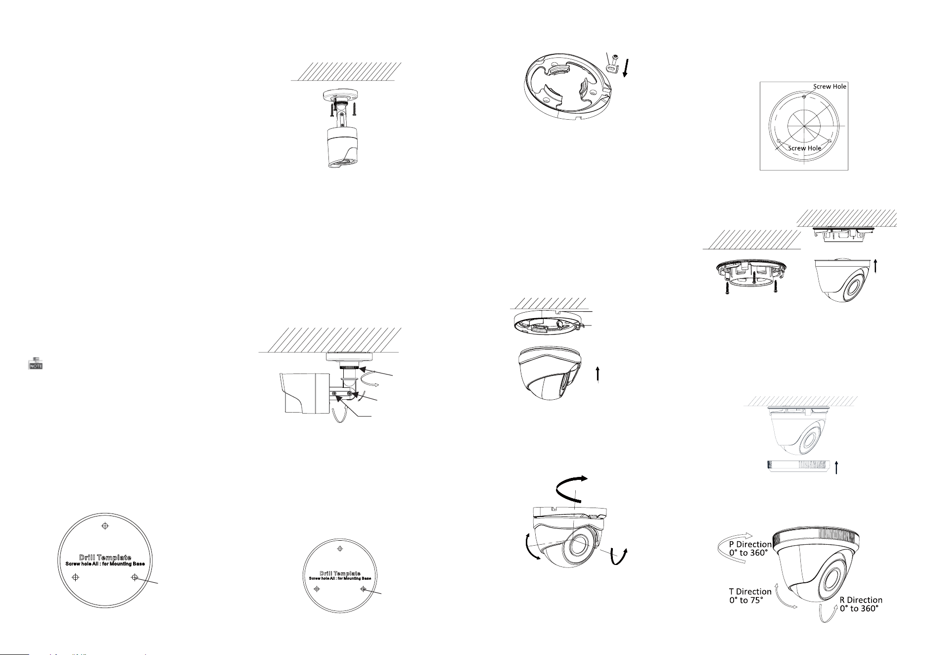
2.2 Installation of Type II Camera
Steps:
1.Drill the screw holes according to the drill
template.
Figure 2-4 The Drill Template
2. Screw the clip plate onto the mounting base
loosely.
Figure 2-5 Screw the Clip Plate
Clip Plate
Figure 2-1 The Drill Template
Screw hole
Figure 2-6 Fix the the Camera
Figure 2-7 3-axis Adjustment
0 to 360°°
0to 75°°
0 to 360°°
Clip Plate
3. Fix the mounting base to the ceiling with the
supplied screws.
4.Route the cables through the side opening and
connect the corresponding power cable and
video cable.
5.Pull out the clip plate and secure the camera
with the trim ring to the mounting base.
6.Push the clip plate in and tighten the lock screw
to secure the trim ring.
2.3 Installation of Type CameraIII
1.Drill the screw holes and the cable hole on the
ceiling according to the supplied drill template.
Steps:
Figure 2-8 The Drill Template
Figure 2-9 Fix the Mounting Base and Camera
2.Fix the mounting base to the ceiling with the
supplied screws.
3.Route the cables through the cable hole and
connect the corresponding power cable and
video cables.
4.Secure the camera to the mounting base and fix
the trim ring to the camera, as shown in the
figure below.
Figure 2-11 3-axis Adjustment
7.Adjust the camera according to the figure 2-7 to
get an optimum angle and tighten the trim ring.
Steps:
1.Drill the screw holes in the ceiling according
to the supplied drill template.
2.Hammer the supplied plastic expansion bolt into
the screw holes.
Screw hole
Side Opening
2.1 Ceiling Mounting for Type I
Camera
Both wall mounting and ceiling mounting are
suitable for type bullet camera. Ceiling mountingI
will be taken as an example in the section. And you
can take steps of ceiling mounting as a reference
if wall mounting is adopted.
2 Installation
Before you start:
l Please make sure that the device in the package
is in good condition and all the assembly parts
are included.
l Make sure that all the related equipment is
power-off during the installation.
l Check the specification of the products for the
installation environment.
l Check whether the power supply is matched
with your power output to avoid damage.
l Please make sure the wall is strong enough to
withstand three times the weight of the camera
and the mounting.
l If the wall is the cement wall, you need to insert
expansion screws before you install the camera.
If the wall is the wooden wall, you can use
self-tapping screw to secure the camera.
l If the product does not function properly,
please contact your dealer or the nearest
service center. Do not disassemble the camera
for repair or maintenance by yourself.
5.Adjust the camera according to the figure below
to get an optimum angle.
j
Figure 2-10 Fix the Trim Ring to the Camera
P Direction
T Direction
R Direction
P Direction
T Direction
R Direction