Loading ...
Loading ...
Loading ...
5
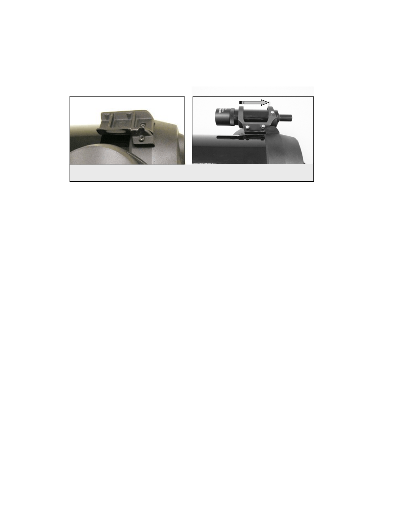
2. Slide the eyepiece end of the finderscope into the front ring of the bracket (the front ring is the one without the
adjustment screws), then through the back ring. It may be necessary to push down the spring loaded pivot screw so
that the finder will pass through the back ring (see figure 1-3)
3. Push the finder back until the O-Ring is snug inside the front ring of the finder bracket.
4. Hand tighten the two alignment thumb screws until they make contact with the finderscope.
Aligning the Finderscope
The finderscope is adjusted using two adjustment screws, located on the top and on the right (when looking though the finder)
of the finder bracket and a spring loaded pivot screw (located on the left side of the bracket). This allows you to turn the top
adjustment screw to move the finderscope up and down, and turn the right adjustment screw to move the finderscope right to
left. The spring loaded pivot screw puts constant pressure on the finder so that the adjustment screws are always making
contact with the finder.
To make the alignment process a little easier, you should perform this task in the daytime when it is easier to locate objects in
the telescope without the finder. To align the finder:
1. Choose a conspicuous object that is in excess of one mile away. This will eliminate any possible parallax effect
between the telescope and the finder.
2. Point your telescope at the object you selected and center it in the main optics of the telescope.
3. Lock the azimuth and altitude clamps to hold the telescope in place.
4. Check the finder to see where the object is located in the field of view.
5. Adjust the thumb screws on the finder bracket, until the cross hairs are centered on the target.
R
R
e
e
m
m
o
o
v
v
i
i
n
n
g
g
t
t
h
h
e
e
L
L
e
e
n
n
s
s
C
C
a
a
p
p
The 8, 9.25 and11" lens cap utilizes a bayonet-type locking mechanism to hold it in place. To remove the lens cap, hold the
cover firmly and rotate the outer edge 1/2” counterclockwise and pull off.
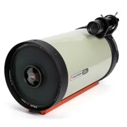
Figure 1-5
The finderscope bracket comes in two pieces; the mounting bracket (left) and the finder bracket (right)
Loading ...
Loading ...
Loading ...