Home
Bookmarks
Home
Pleasant Hearth
Pleasant Hearth VFS2-PH20DT User Manual
Page 6
Pleasant Hearth VFS2-PH20DT 20,000 Btu 23.5 In. Compact Gas Vent Free Stove
User Manual - Page 6
For VFS2-PH20DT.
PDF File Manual
,
62 pages
,
Read Online
|
Download pdf file
CAUTION - FOR YOUR SAFETY
SERVICE HINTS
When Gas Pressure Is Too Low
IMPORTANT SAFETY INFORMATION
SAFETY PILOT
ELECTRIC PUSH BUTTON IGNITION SYSTEM
THERMOSTAT HEAT CONTROL
DUAL FUEL CAPABILITY
BLOWER KIT (OPTIONAL)
LOCAL CODES
UNPACKING
AIR FOR COMBUSTION AND VENTILATION
PRODUCING ADEQUATE VENTILATION
Confined and Unconfined Space
Unusually Tight Construction
DETERMINING FRESH-AIR FLOW FOR HEATER LOCATION
Determining if You Have a Confined or Unconfined Space
Ventilation Air From Inside Building
Ventilation Air From Outdoors
CHECK GAS TYPE
CLEARANCES TO COMBUSTIBLES
Minimum Clearances For Side Combustible Material, Side Wall and Ceiling
Fig. 6 - Minimum Clearance to Combustible Material
BLOWER INSTALLATION (OPTIONAL)
VENT-FREE BLOWER INFORMATION
CLEANING
BATTERY INSTALLATION
LEG INSTALLATION (If required)
GAS SELECTION INSTRUCTIONS
Do not operate the appliance between
Fig. 8 - Selector Valve
CONNECTING TO GAS SUPPLY
Installation Items Needed (Not Provided)
CHECKING GAS CONNECTIONS
Pressure Testing Gas Supply Piping System Test Pressures In Excess Of 1/2 PSIG ( 3.5kPa )
Test Pressures Equal To or Less Than 1/2 PSIG (3.5 kPa)
Pressure Testing Heater Gas Connections
Fig. 12 - Equipment Shutoff Valve
WHAT TO DO IF YOU SMELL GAS
Fig. 15 - Control Knob
Fig. 16 - Pilot
INSPECTING BURNERS
PILOT FLAME PATTERN
BURNER FLAME PATTERN
BURNER ORIFICE HOLDER AND PILOT AIR INLET HOLE
CABINET
Air Passageways
Exterior
ACCESSORIES
NOTICE: All accessories may not be available for all heater models.
PRECAUCIÓN- PARA SU SEGURIDAD
TABLA DE CONTENIDO
CONSEJOS DE SERVICIO
Cuando la presión del gas es demasiado baja
INFORMACIÓN DE SEGURIDAD IMPORTANTE
INFORMACIÓN DE SEGURIDAD
Aire de ventilación desde el interior del
Aire de ventilación desde el exterior
Fig. 6 - Espacio libre mínimo a material combustible
Instrucciones Para La Instalación De Batería
INSTALACIÓN DE LOS LEÑOS (si se requiere)
INSTRUCCIONES DE SELECCIÓN DEL GAS
No opere el aparato entre posiciones bloqueadas.
45 Fig. 8 - Válvula selectora
CONEXIÓN AL SUMINISTRO DE GAS
Artículos de instalación requeridos (no suministrados)
Fig. 12 - Válvula de cierre del equipo
Fig. 15 - Perilla de control
Fig. 16 - Piloto
ACCESORIOS
AVISO: Pueden no estar disponibles todos los accesorios para todos los modelos de calefactor.
Garantía
Page 6/62
Page 1
Page 2
Page 3
Page 4
Page 5
Page 6
Page 7
Page 8
Page 9
Page 10
Page 11
Page 12
Page 13
Page 14
Page 15
Page 16
Page 17
Page 18
Page 19
Page 20
Page 21
Page 22
Page 23
Page 24
Page 25
Page 26
Page 27
Page 28
Page 29
Page 30
Page 31
Page 32
Page 33
Page 34
Page 35
Page 36
Page 37
Page 38
Page 39
Page 40
Page 41
Page 42
Page 43
Page 44
Page 45
Page 46
Page 47
Page 48
Page 49
Page 50
Page 51
Page 52
Page 53
Page 54
Page 55
Page 56
Page 57
Page 58
Page 59
Page 60
Page 61
Page 62
Contents
Table of Contents
Search
Previous
Next
Bookmarks
Loading ...
Loading ...
Loading ...
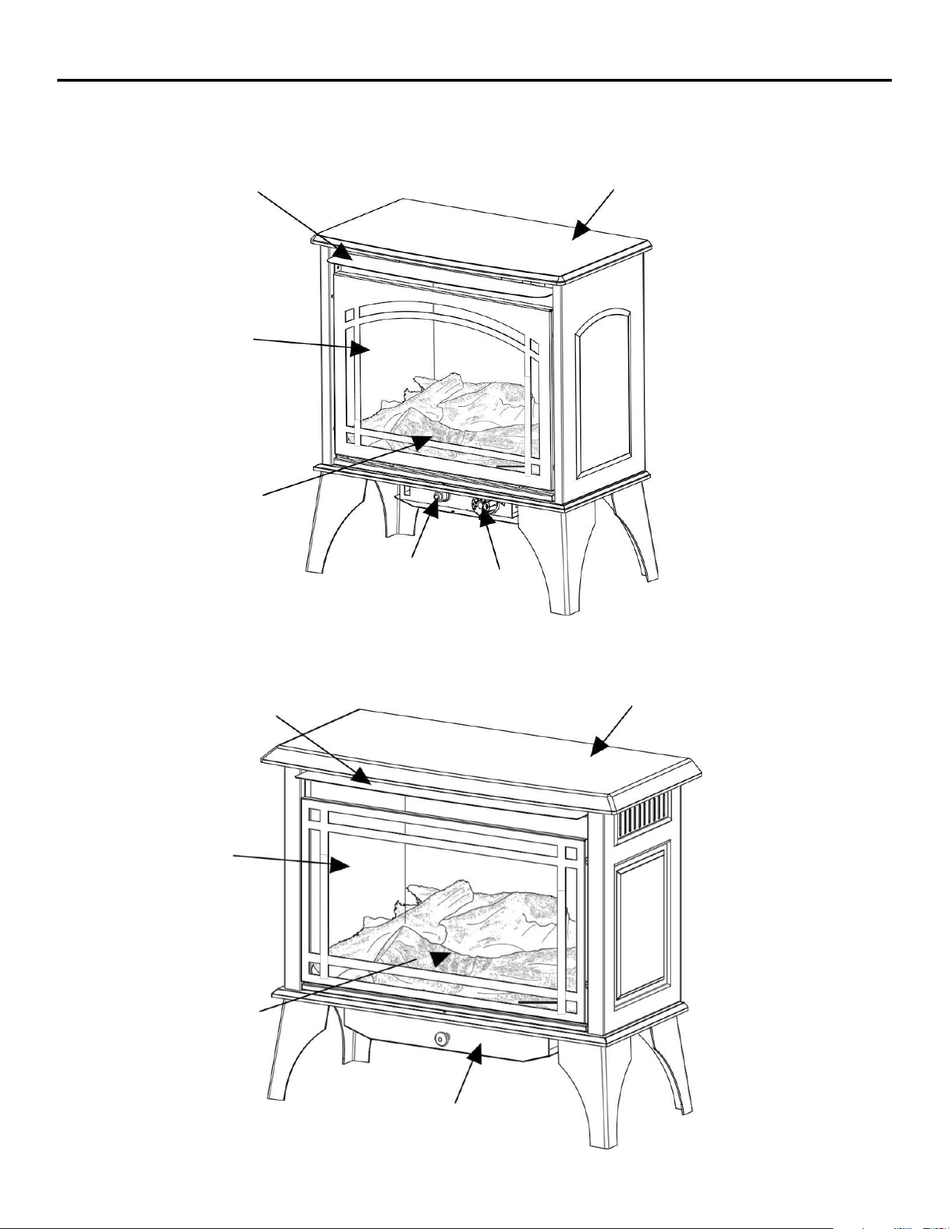
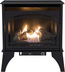
PRODUCT IDEN
T
I
FI
CATIO
N
5
H
ood
Scr
een
Logs
Stove C
abi
net
H
ood
Stove C
abi
net
Sc
r
e
Igni
tor
But
ton
Cont
rol
Kn
ob
en
Logs
Cont
rol
Cover
Loading ...
Loading ...
Loading ...
File type: PDF
File name: 92063972_vfs2-ph20dt.pdf
File size: 4.17 MB
File Language: English
Pages: 62
Author: Pleasant Hearth
File created: 2024-01-22
Published:
2024-01-22
Updated: 2024-01-22
Download File
Table of Contents
×
CAUTION - FOR YOUR SAFETY
1
SERVICE HINTS
3
When Gas Pressure Is Too Low
3
IMPORTANT SAFETY INFORMATION
4
SAFETY PILOT
7
ELECTRIC PUSH BUTTON IGNITION SYSTEM
7
THERMOSTAT HEAT CONTROL
7
DUAL FUEL CAPABILITY
7
BLOWER KIT (OPTIONAL)
7
LOCAL CODES
7
UNPACKING
7
AIR FOR COMBUSTION AND VENTILATION
8
PRODUCING ADEQUATE VENTILATION
8
Confined and Unconfined Space
8
Unusually Tight Construction
8
DETERMINING FRESH-AIR FLOW FOR HEATER LOCATION
9
Determining if You Have a Confined or Unconfined Space
9
Ventilation Air From Inside Building
10
Ventilation Air From Outdoors
10
CHECK GAS TYPE
11
CLEARANCES TO COMBUSTIBLES
11
Minimum Clearances For Side Combustible Material, Side Wall and Ceiling
12
Fig. 6 - Minimum Clearance to Combustible Material
12
BLOWER INSTALLATION (OPTIONAL)
13
VENT-FREE BLOWER INFORMATION
13
CLEANING
13
BATTERY INSTALLATION
14
LEG INSTALLATION (If required)
14
GAS SELECTION INSTRUCTIONS
15
Do not operate the appliance between
15
Fig. 8 - Selector Valve
15
CONNECTING TO GAS SUPPLY
16
Installation Items Needed (Not Provided)
17
CHECKING GAS CONNECTIONS
19
Pressure Testing Gas Supply Piping System Test Pressures In Excess Of 1/2 PSIG ( 3.5kPa )
19
Test Pressures Equal To or Less Than 1/2 PSIG (3.5 kPa)
19
Pressure Testing Heater Gas Connections
19
Fig. 12 - Equipment Shutoff Valve
19
WHAT TO DO IF YOU SMELL GAS
20
Fig. 15 - Control Knob
20
Fig. 16 - Pilot
20
INSPECTING BURNERS
21
PILOT FLAME PATTERN
21
BURNER FLAME PATTERN
22
BURNER ORIFICE HOLDER AND PILOT AIR INLET HOLE
22
CABINET
23
Air Passageways
23
Exterior
23
ACCESSORIES
28
NOTICE: All accessories may not be available for all heater models.
28
PRECAUCIÓN- PARA SU SEGURIDAD
32
TABLA DE CONTENIDO
34
CONSEJOS DE SERVICIO
34
Cuando la presión del gas es demasiado baja
34
INFORMACIÓN DE SEGURIDAD IMPORTANTE
35
INFORMACIÓN DE SEGURIDAD
36
Aire de ventilación desde el interior del
41
Aire de ventilación desde el exterior
41
Fig. 6 - Espacio libre mínimo a material combustible
43
Instrucciones Para La Instalación De Batería
45
INSTALACIÓN DE LOS LEÑOS (si se requiere)
45
INSTRUCCIONES DE SELECCIÓN DEL GAS
46
No opere el aparato entre posiciones bloqueadas.
46
45 Fig. 8 - Válvula selectora
46
CONEXIÓN AL SUMINISTRO DE GAS
47
Artículos de instalación requeridos (no suministrados)
48
Fig. 12 - Válvula de cierre del equipo
50
Fig. 15 - Perilla de control
51
Fig. 16 - Piloto
51
ACCESORIOS
59
AVISO: Pueden no estar disponibles todos los accesorios para todos los modelos de calefactor.
59
Garantía
61
Search:
×
Search