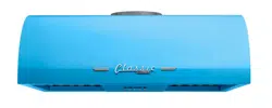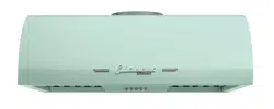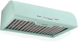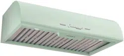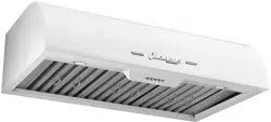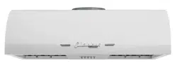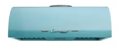
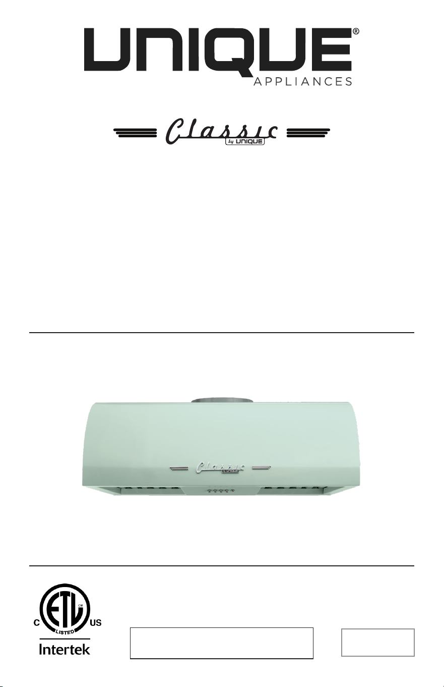
CLASSIC RETRO BY UNIQUE
24” RANGE HOOD
OWNER’S GUIDE
serial number:
MODEL NUMBERS:
UGP-24CR RH W, UGP-24CR RH B, UGP-24CR RH T,
UGP-24CR RH LG, UGP-24CR RH RB
AUG21V1

2
TABLE OF CONTENTS
SAFETY NOTICE 03
PRE INSTALLATION 06
NECESSARY TOOLS 08
PARTS INCLUDED 09
PARTS LIST 09
INSTALLATION PROCEDURE 10
OPERATING INSTRUCTIONS 15
TROUBLESHOOTING 15
MAINTENANCE 16
TECHNICAL SPECIFICATIONS 17
WIRING DIAGRAM 17
PARTS DIAGRAM AND LIST 18
WARRANTY 20
APPLIANCE INFORMATION 22
RATING LABEL 22
PRODUCT REGISTRATION 22
CONTACT US 23
3
SAFETY NOTICES
Approved for residential type units for residential use only read these
instructions and be safe.
Please read these instructions completely before starting.
The installation of the appliance must respect all codes.
Important: Save these instruction so that you can provide the electrical
inspector in your area.
Safety Warning: Turn o the circuit in the electrical panel and lock
front panel to connect the cord of this unit.
Power Requirement: 110V-120V/60HZ
CAUTION: USE THIS PRODUCT FOR GENERAL FAN ONLY. DO
NOT USE THIS PRODUCT TO EXHAUST FUMES OR HAZARDOUS OR
EXPLOSIVE MATERIALS.
WARNING: TO REDUCE THE RISK OF FIRE, ELECTRICAL SHOCK
OR INJURY TO PEOPLE, OBSERVE THE FOLLOWING:
1. Use this unit only for the purposes intended by the manufacturer.
If you have any questions about this product, contact the
manufacturer.
2. Before the machine’s maintenance or cleaning, turn o the
electrical panel and lock the panel blocking feature to prevent from
accidentally activating the power. If it is not possible to lock the
access panel, attach a highly visible label to the electrical panel.
3. A qualified person should perform the installation and wiring of the
electricity in accordance with all codes and all standards, including
fire resistance rating.
4. When you use hood together with stove, please do not close the
window and door of the kitchen. Because during the fuel stove
working, which will consume lots of air, so do open the door and
window to make the kitchen ventilating, to avoid any suocation.
5. It is important to provide sucient air for proper combustion of
heating equipment and proper evacuation of gases through the
chimney pipe to prevent back flow of air. Follow the instructions and
safety standards of the manufacturers of heating equipment, such as
those published by the National Fire Protection Association (NFPA),
the American Society for Heating, Refrigeration and Air Conditioning
Engineers (ASJRAE) and the code authorities in your area.
6. When cutting or drilling into wall or ceiling, be sure not to damage
electrical wiring or other access to public service.
7. Always evacuate outside the conduit system.
4
To reduce the risk of fire and to properly exhaust air, be sure that the
pipe is leading outside, do not exhaust air into the space between the
walls, ceilings, attics, crawl spaces or garages.
WARNING — GROUNDING INSTRUCTIONS
This device must be grounded. In the event of an electrical short circuit,
grounding reduces the risk of electric shock by providing an escape
wire for the electric current. This appliance is equipped with a cord with
a grounding wire with a grounding plug. The plug must be inserted into
a properly installed and grounded outlet.
CAUTION — INCORRECT GROUNDING CAN CAUSE RISK OF
ELECTRIC SHOCK
If you are unsure whether the device is grounded properly or if the
grounding instructions are not fully understood, consult a qualified
electrician.
Do not use an extension cord. If the power cord is too short, have a
qualified electrician install an outlet near the device.
WARNING — TO REDUCE THE RISK OF FIRE OR ELECTRIC
SHOCK, DO NOT USE THIS HOOD WITH EXTERNAL SOLID STATE
SPEED CONTROLLERS
WARNING — TO REDUCE THE RISK OF FIRE, USE ONLY
METAL DUCTS
Install this hood in accordance with all the requirements mentioned.
WARNING — TO REDUCE THE RISK OF FIRE
1. Never leave the stove unattended when it is at a high temperature.
Boil overs cause smoke and fat that overflows can ignite. Heat the oil
slowly at a low or medium temperature.
2. Always operate the hood when you use the stove to high heat or
when you Flame.
3. Clean ventilating fans frequently. Do not let fat accumulate on the
filters or propellers.
4. Use proper pan size. Always use a pot size appropriate to the stove
element.
5. Do not touch on-working or o-soon bulb, to avoid any thorny.
SAFETY NOTICES

5
WARNING — TO AVOID INJURING SOMEONE IN A GREASE
FIRE, FOLLOW THE FOLLOWING:
1. SMOTHER FLAMES with a lid to the dimensions of the cooking hobs,
a cookie sheet or other metal tray, then turn o the gas or power
supply of the stove. BE CAREFUL NOT TO BURN YOURSELF. If the
flames do not go out immediately, LEAVE AND CALL THE FIRE
DEPARTMENT.
2. NEVER PICK UP A FLAMING PAN. You could be hurt.
3. DO NOT USE WATER, including Dish towels or wet towels-a violent
steam explosion of dew may be occurred.
4. Use an extinguisher only if:
• You are sure to have a Class ABC extinguisher that you know how
to use.
• The fire is small and confined to the area where it was formed.
• Firefighters were called.
• You can fight against the fire with an exit behind you.
OPERATIVE MODE
Always leave safety grills and filers in place. Without the presence of
these blowers could catch hair, fingers or clothing. The manufacturer is
not liable if detailed in this manual for installation info, maintenance and
proper use of the product are not observed. The manufacturer declines
all responsibility for any injury caused by negligence. This product is
manufactured for internal use. Do not use this appliance outdoors.
SAFETY NOTICES

6
PRE INSTALLATION
CAUTION
Due to the weight and size of these vent hoods and to reduce the
risk of personal injury or damage to the product, TWO, TO THREE
PEOPLE ARE REQUIRED FOR PROPER INSTALLATION.
• Please read the instructions carefully. Unpack the range hood
and check that all functions are working before installing.
• Ensure that the voltage (V) and the frequency (Hz) indicated on
the sticker match the voltage and frequency at the installation site.
• Check that the area behind the installation surface to be drilled is
clear of any electrical cables or pipes, etc.
• The surfaces of the range hood are very easily damaged during
installation if scratched or bumped by tools. Please take care to
protect the surfaces during installation.
• Protect the cooktop surface below with cardboard, or the like, to
prevent damage.
• The manufacturer shall not be held liable for consumer’s failure
to observe and follow all pre-installation procedures and safety
regulations.
• The vertical distance from the cooking surface to the bottom of
the range hood should be at least 24” to 36” for best performance.
• Determine if your installation will be top venting or back venting,
and ensure that the openings in the cabinet or wall are in the
appropriate locations and appropriate size.
• If this is a new installation, choose the venting method that suits
your needs. Cut out openings for the damper and for power
access in the cabinet bottom or exterior wall, depending on the
installation method chosen.
7
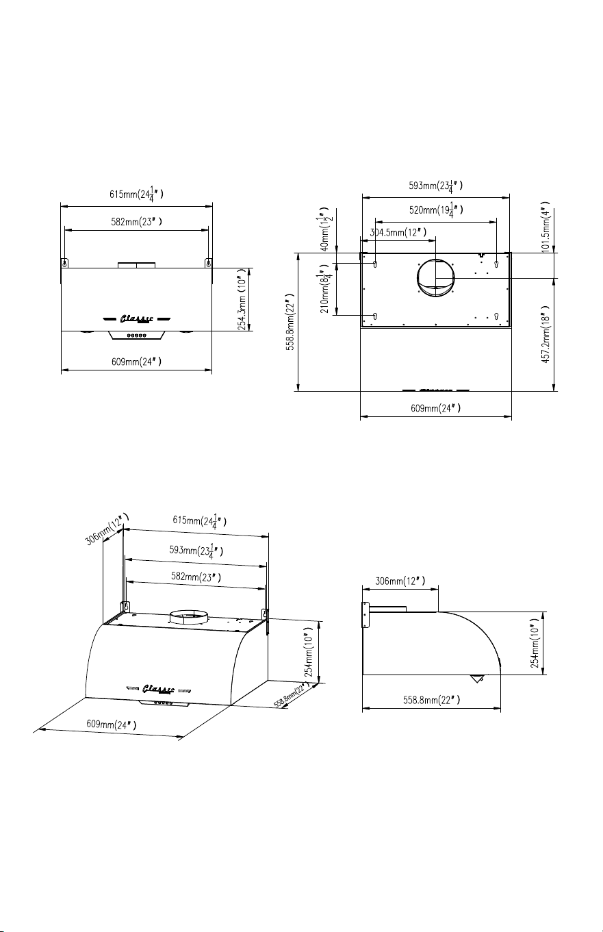
PRE INSTALLATION
Side View3/4 View
Front View Top View
MEASUREMENTS
8
PRE INSTALLATION
DUCT PLANNING
• The ventilation hood is equipped for 8” round ducts. This hood can
be ventilated vertically through the top cabinet or ceiling. A duct
transition piece is provided for vertical exhaust. You can use elbows
(sold separately) to ventilate horizontally through the rear wall.
• Determine the exact position of the hood.
• Plan the route to vent the ventilation duct to the outside.
• Use the shortest and straightest path possible. For satisfactory
performance, the length of the duct should not exceed 12.5 feet of
equivalent length for all duct configurations.
• Use only metal ducts.
WALL FRAMING FOR ADEQUATE SUPPORT
WARNING
THESE VENT HOODS ARE HEAVY. ADEQUATE STRUCTURAL
SUPPORT IS REQUIRED.
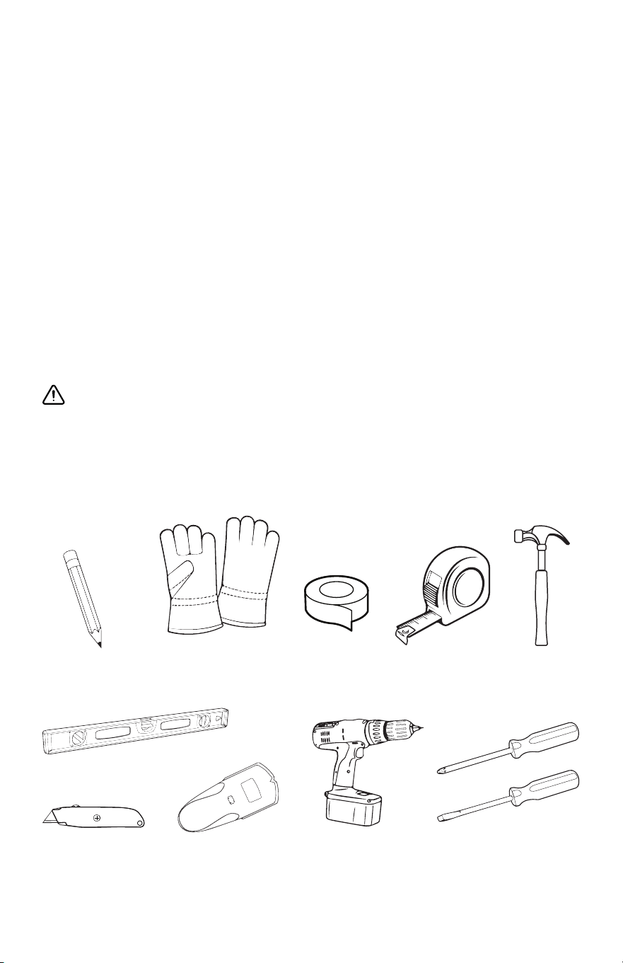
Aluminum
Foil Tape
Hammer
NECESSARY TOOLS
Marker or
pencil
Safety
Gloves
Level
Utility knife Stud finder
Powered
screwdriver or
drill
Measuring
tape
Flat-blade
and Phillips
screwdrivers
9
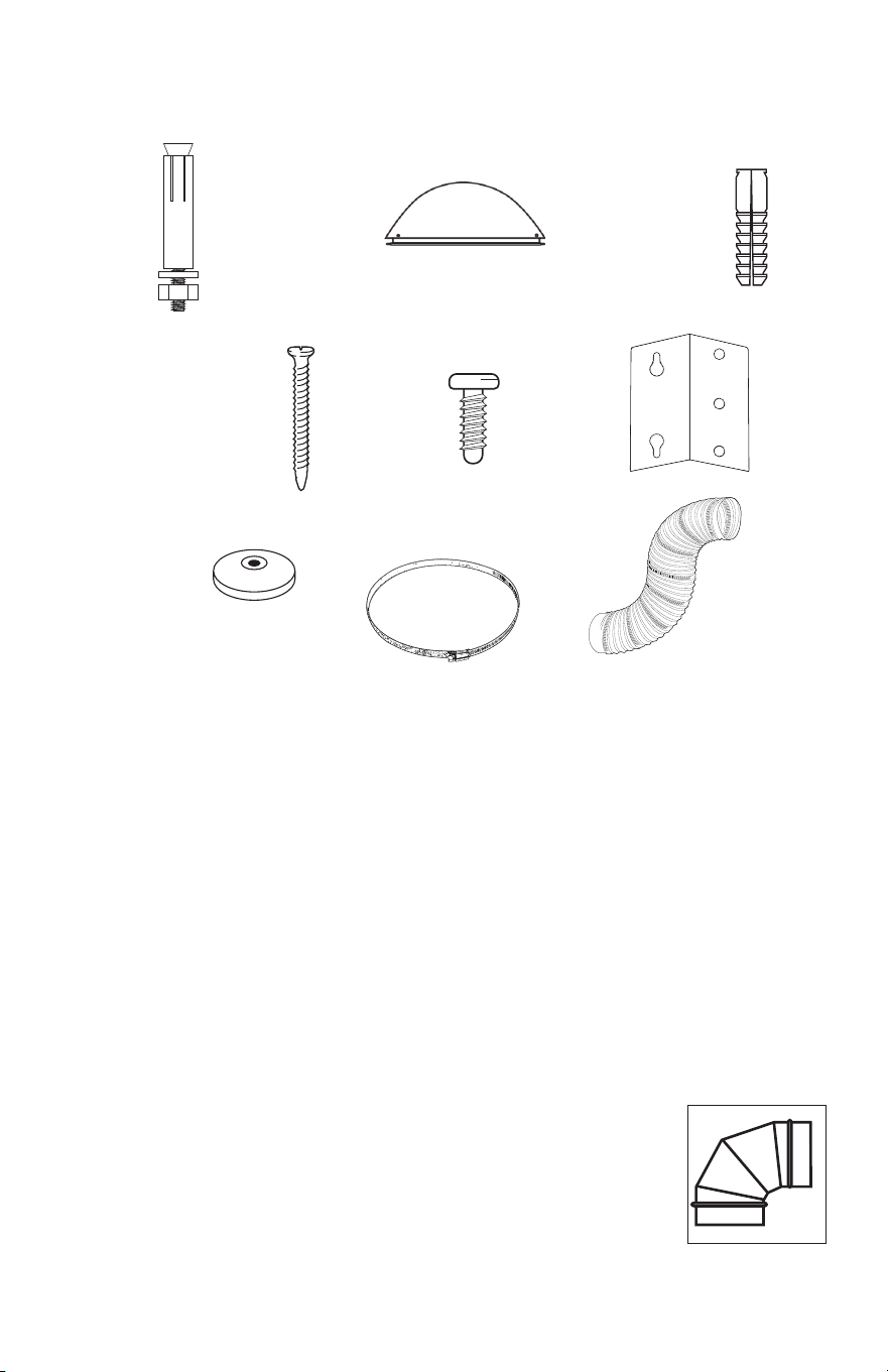
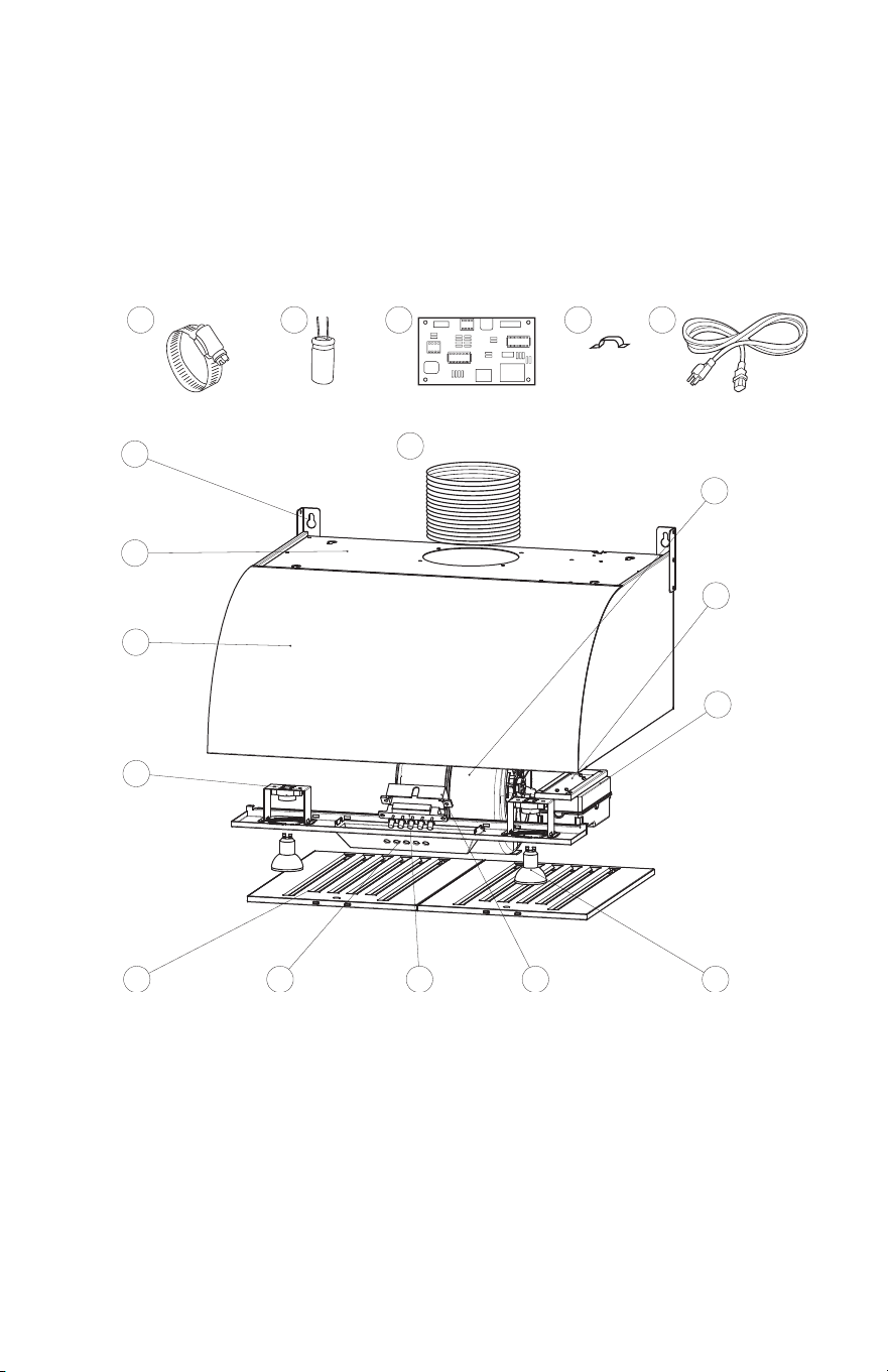
PARTS INCLUDED
PARTS LIST
A) Metal anchors (concrete installations) - 4 pcs
B) Damper Flap - 1 (could be attached to range hood)
C) Plastic Anchors (drywall installations)- 10 pcs
D) ST4*4 x 35 mm wood screws - 10 pcs
E) ST4*4 x 12 mm metal screws - 6 pcs
(use only if not installing into the top cabinets)
F) Metal Hinges - 2 pcs
(use only if not installing into the top cabinets)
G) Beveled Washers - 10 pcs
H) Metal Duct Clamp - 1
I) 7.5” Round Duct - 1
J) Elbow Duct - 1
(Sold separately for rear wall installation)
A B C
G H I
FD E
J
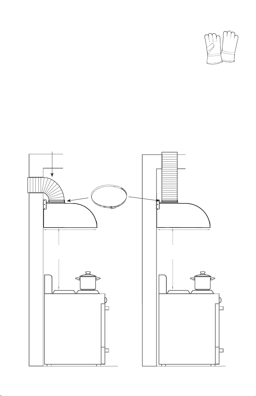
10
INSTALLATION PROCEDURES
MIN. 24”
MAX. 36”
MIN. 24”
MAX. 36”
Caution: The range hood has sharp edges
Please wear protective work gloves to remove parts,
installation, cleaning and servicing.
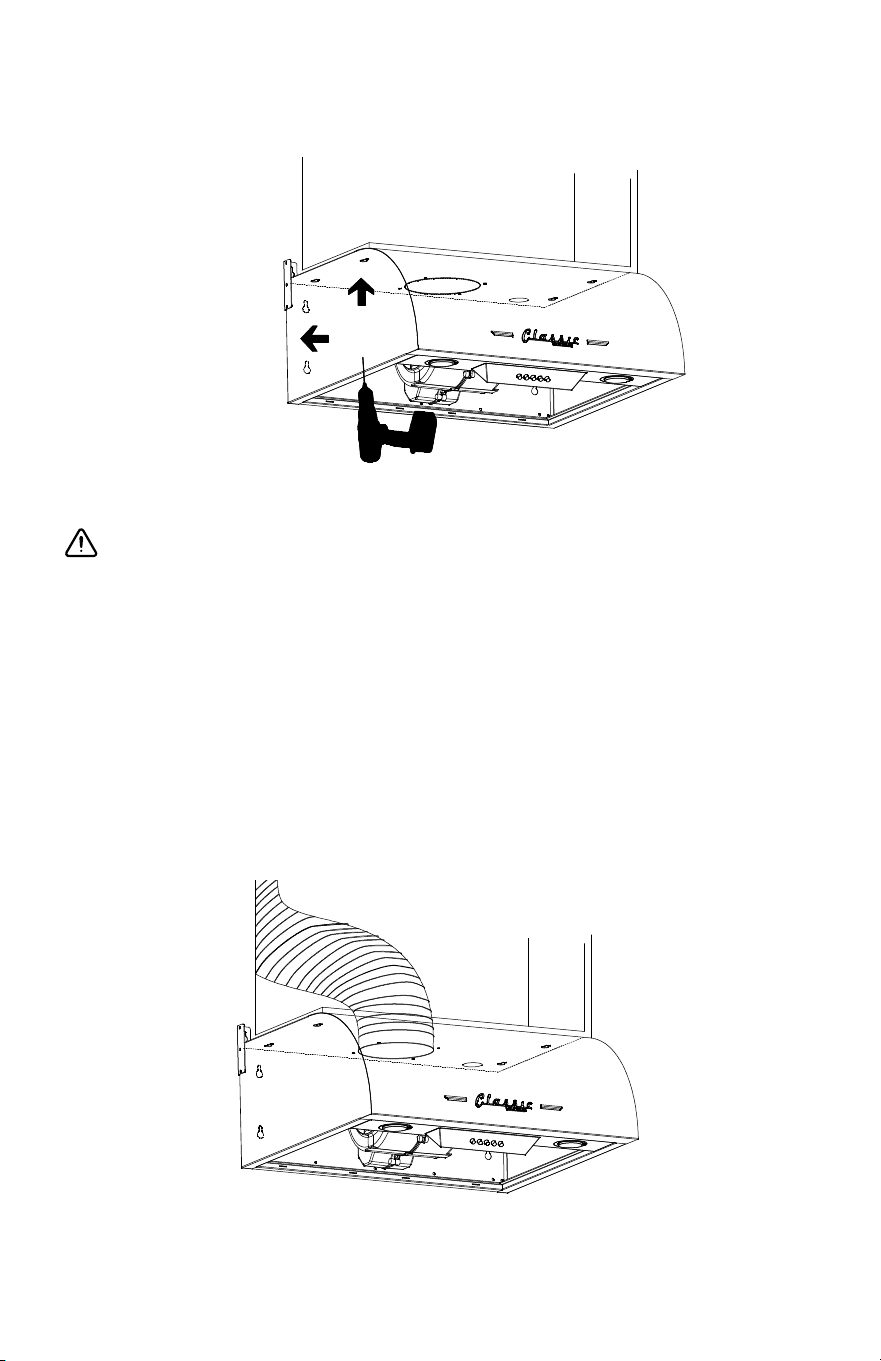
Step 1:
• Connect the Duct into the Damper.
• Secure the Duct around the Damper with the Duct Clamp.
Important: For best results, the mounting height of range hood
should be 65 - 75 cm (24” - 36”) above the top of the range.
SECURE DUCT
AROUND
DAMPER WITH
DUCT CLAMP
(INCLUDED)
STEEL ELBOW DUCT
RECOMMENDED FOR WALL
MOUNTED INSTALLATION
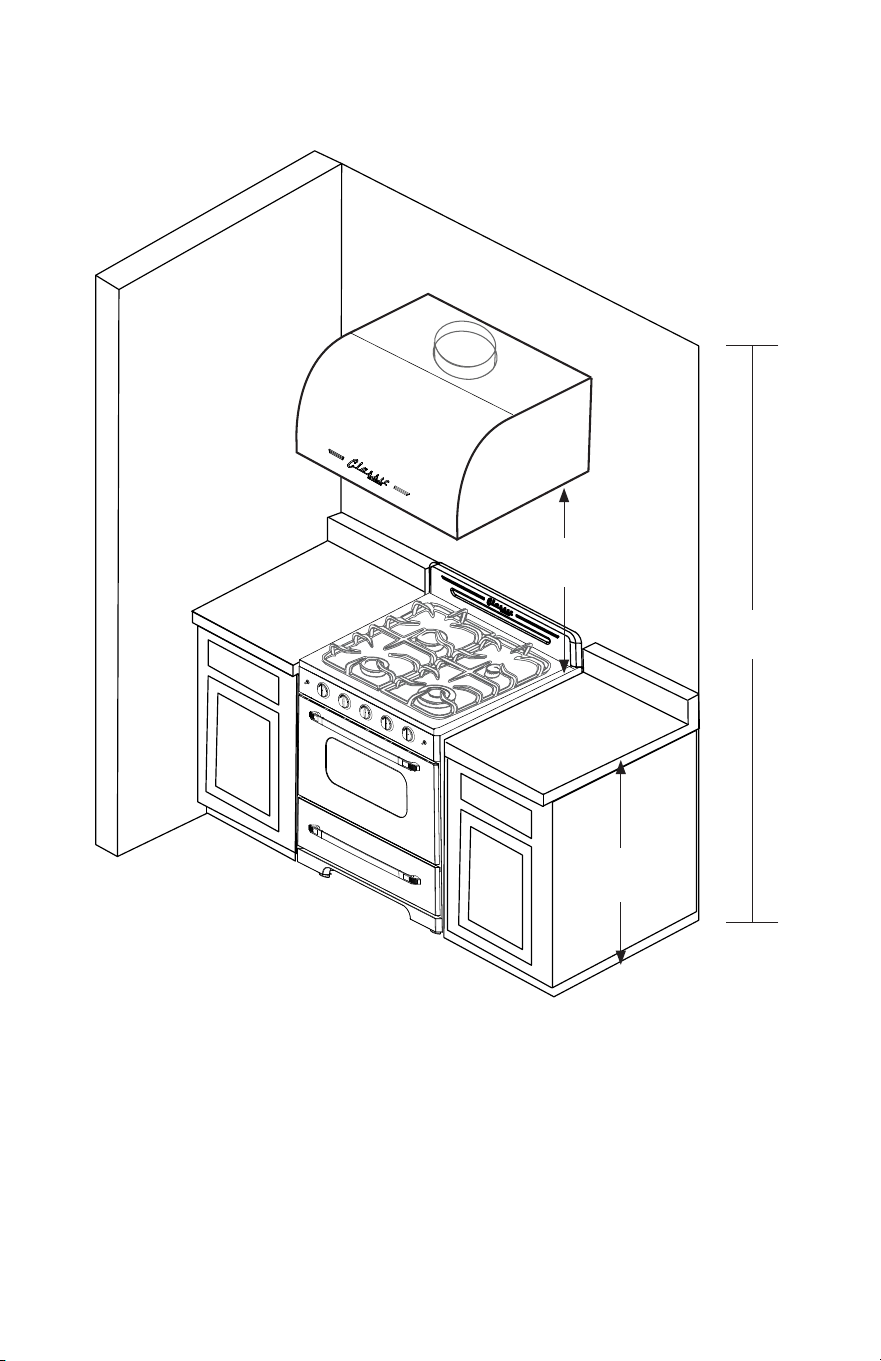
11
INSTALLATION PROCEDURES
Step 2:
Caution: When installing the hood, the height should not be too
high or too low. Before the installation, please inspect the maximum
height of your ceiling and bonnet. Too high, will aect the eciency
of the hood; too low, stove temperature will damage some parts
of the hood. So the installation height requirement is: the distance
between the bottom of the hood to the surface of the cooktop is
Max 36” - Min 24” (as figure showing)
36”
MIN. 24”
MAX. 36”
CEILING
HEIGHT
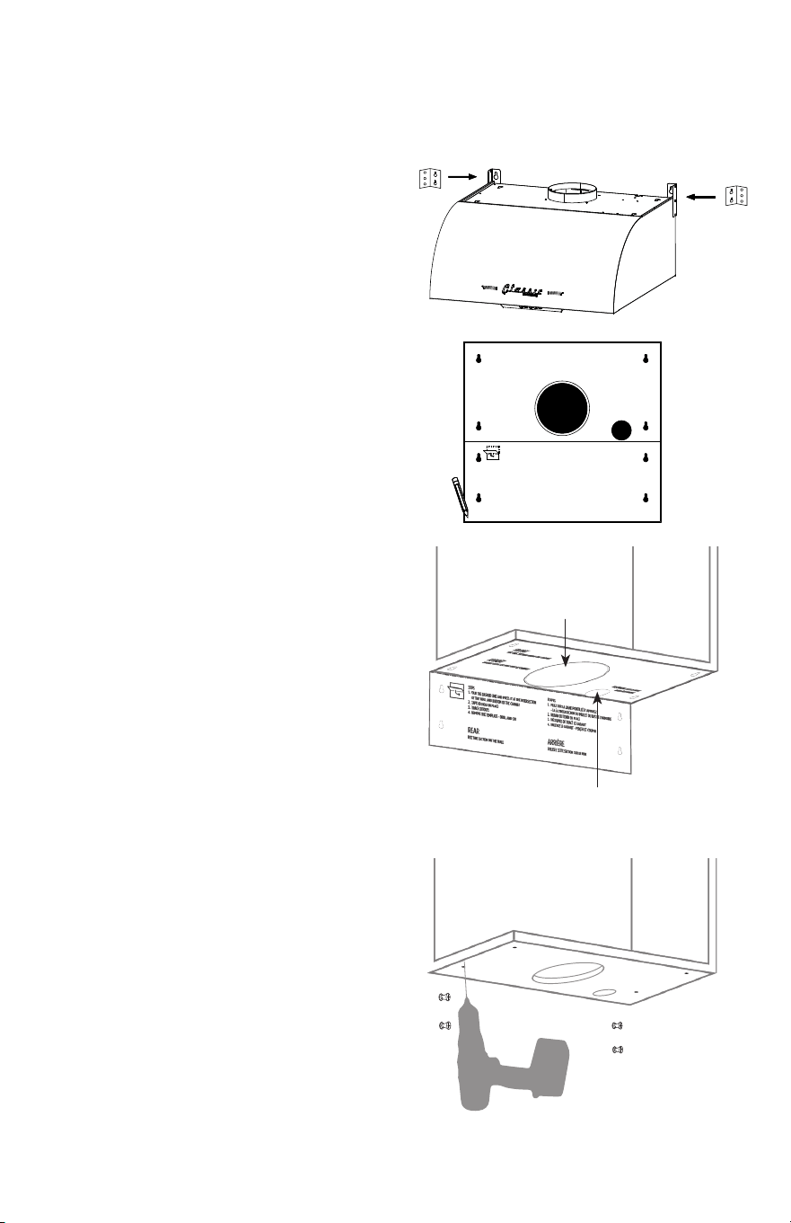
12
INSTALLATION PROCEDURE
Top and rear mount
installation
Due to the weight of the unit, it
is recommended to mount the
hood at the bottom of the upper
cabinet and then fix it to the wall
to avoid gaps.
1. Use the installation template
cut-outs to mark the necessary
holes on the back and top
of the hood with a pencil or
marker.
2 Remove the template after
marking
3. Use the wall stud finder to
identify the number of drywall
anchors required.
4. Drill four (4) 5/16" (8 mm)
holes into the wall at each of
the marked locations. Insert
the drywall anchors into wall
holes and firmly tap them
into place. Insert screws into
anchors and leave 1/4" out for
range hood to hang on.
5. Remove an electrical and
duct access hole in the upper
cabinet.
DRYWALL ANCHORS
ELECTRICAL
ACCESS HOLE
DUCT HOLE
(USE HINGES ONLY IF NOT INSTALLING
UPPER SCREWS INTO THE TOP CABINETS)
STEPS
1. FOLD THE DASHED LINE AND PRESS IT AT THE INTERSECTION
OF THE WALL AND BOTTOM OF THE CABINET
2. TAPE OR HOLD IN PLACE
3. TRACE CUTOUTS
4. REMOVE THE TEMPLATE - DRILL AND CUT
ÉTAPES
1. PLIEZ SUR LA LIGNE POINTILLÉ ET APPUYEZ
- LA À L'INTERSECTION DU MUR ET DU BAS DE L'ARMOIRE
2. RUBAN OU TENIR EN PLACE
3. DÉCOUPES DE TRACÉ LE GABARIT
4. ENLEVEZ LE GABARIT - PERÇER ET COUPER
USE THIS SECTION ON THE WALL
REAR
UTILISEZ CETTE SECTION SUR LE MUR
ARRIÈRE
USE THIS SECTION UNDER THE CABINET
FRONT
UTILISEZ CETTE SECTION SOUS LE CABINET
AVANT
TROU ÉLECTRIQUE
ELECTRICAL ACCESS HOLE
13
INSTALLATION PROCEDURE
THESE STEPS REQUIRE LIFTING AND HANGING AT THE SAME
TIME - USE TWO/THREE PEOPLE
6. Locate the top (cabinet) holes and line up hood holes, while also
lining up to holes with the protruding wall screws.
7. Fasten the hood to the bottom of the cabinet by tightening
screws with a drill or screwdriver.
8. Tighten the screws to fix the hood to the wall once it is fixed to
the cabinet.
9. Run the ducting through cabinet and the electrical cables through
electrical access hole.
TIGHTEN
TOP FIRST
TIGHTEN
TO WALL
SECOND
14
INSTALLATION PROCEDURE
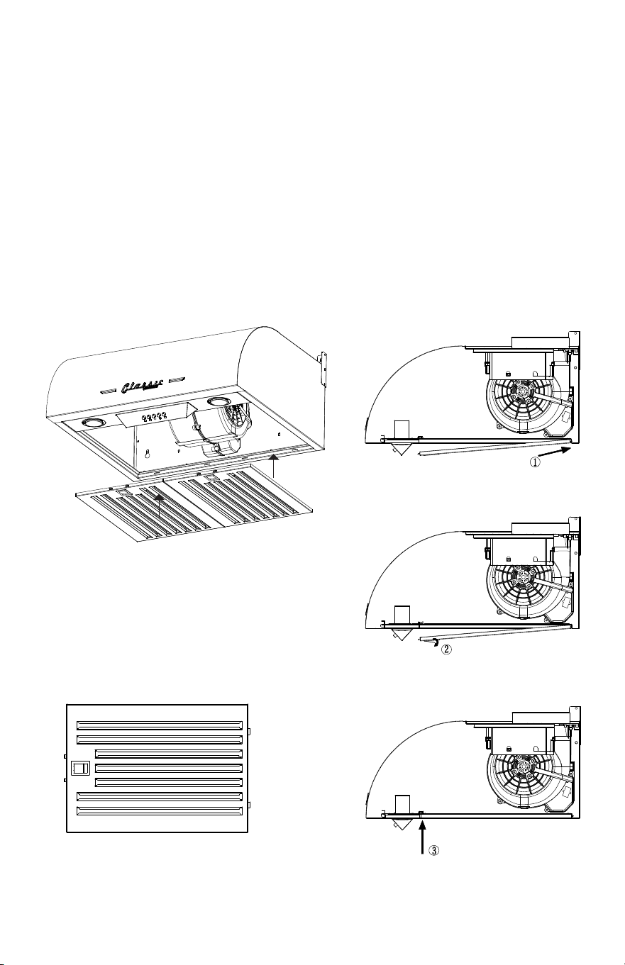
Metal Filter Installation
1. Install the filters by inserting at an angle towards the rear of the
range hood. (Fig 2)
2. Push the filter up and insert front of filter into front tabs. Slightly
lower the filter then slide back until it is in proper position. Fig 3 & 4)
DRIP TRAY
FILTER X2
(FIG 1) (FIG 2)
(FIG 3)
(FIG 4)
15
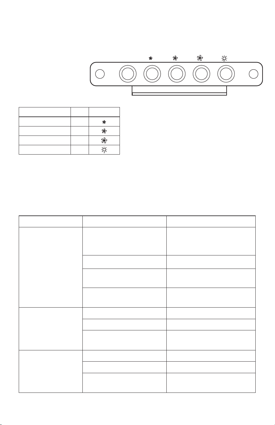
OPERATING INSTRUCTIONS
Function Buttons:
OFF F1
OFF
LOW SPEED F2
MEDIUM SPEED F3
HIGH SPEED F4
LED LIGHT F5
F1 F2 F3 F4 F5
OFF
Touch Controls
Fan Buttons: Power on by pressing
any button of F2/F3/F4, fan starts
and F5 light automatically but does
not blink.
TROUBLESHOOTING
PROBLEM CAUSE SOLUTION
After Installation, motor and
lights are not working.
The power is not on Make sure the circuit breaker and the
unit’s power is ON. Use a voltage meter
to check the power supply
The wire connection is not secure Check and tighten wire connection
The touch panel and processor board
wiring are disconnected
Check wire continuity from control panel
to processor board
The touch panel and processor board
is defective
Replace the control panel or processor
board
Lights are working, but
motor(s) is not.
The motor(s) is defective Replace the motor
The capacitor(s) is defective Replace capacitor(s)
The control panel or processor board
is defective
Replace the control panel or processing
board
The range hood is vibrating The blower system is not secure Tighten the squirrel cage
The squirrel cage is not balanced Replace the squirrel cage
Hood is not secured in place Check the installation of hood, tighten
the mounting bracket
16
MAINTENANCE
CAUTION: NEVER PUT YOUR HANDS INSIDE THE RANGE HOOD
WHILE IT IS IN OPERATION.
CLEANING
For best performance, clean the range hood regularly.
1. Use only mild soap or cleaning solutions to clean the exterior
surface of the range hood. Use a soft cloth to dry the surface.
2. Stainless Steel Filters: For daily cleaning, use warm soapy water
and a soft cloth. Pat dry and finish with a damp microfiber cloth.
The filters can also be cleaned in the dishwasher.
3. Clean the hood assembly every 6 months.
4. Do not clean the electrical components or motor with water or
other liquids.
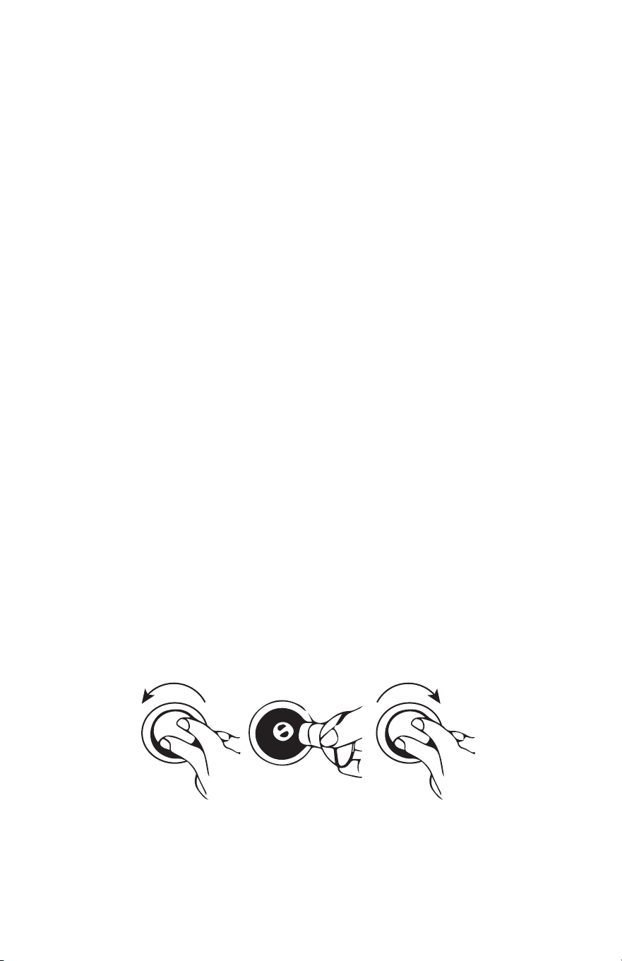
REPLACING LED LIGHT BULBS
CAUTION: THE LAMP UNIT MAY BE HOT! WAIT UNTIL THE UNIT IS
COLD. Before attempting to replace the bulbs, make sure the unit is
turned o and unplugged.
Note: Bulb Size GU10.
1. Turn counterclockwise and remove the bulb from the board.
2. Connect a new bulb and turn it clockwise to lock it in place.
17
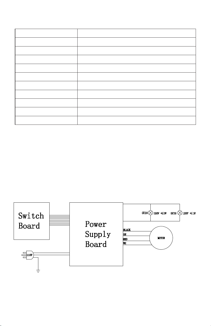
WIRING DIAGRAM
TECHNICAL SPECIFICATIONS
MODEL UGP 24 CR RH
SIZE
24” (61 cm)
RATED POWER
500 CFM
CONTROLS
3 speed power control
NOISE LEVEL
Below 65 dbA
LIGHTS
1.5W LED Lamps x 2
CLEANING
Dishwasher safe stainless steel bae filters
DIMENSIONS
10” H x 24.25” W x 22” D
WEIGHT (UNBOXED)
31 lbs / 14 kg
POWER RATING
110V, 60Hz
CERTIFICATION
ETL Certified
Made in China
18
PARTS DIAGRAM AND LIST
20 19 17 16 15
18
1
2
3
4
6 7 8 9 10
12
13
14
19
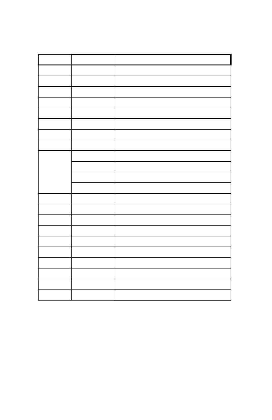
PARTS DIAGRAM AND LIST
Item # Part Number Description
CLASSIC RETRO LOGO Unique Classic Logo
3 UGP-SNG01 Coloured Range Hood Body ASSY (not for individual sale)
1 UGP-SNG02 Wall Mounting Bracket for UGP-30/24CR RH
4 UGP-SNG07 Lamp Mount Bracket for UGP-30/24CR RH
6 UGP-SNG22 Air Filter for UGO-24CR RH (2 per unit)
8 UGP-SNG09 Electric Switch ASSY for UGP-30/24CR RH
9 UGP-SNG11 Electric Switch Mounting Bracket for UGP-30/24CR RH
10 UGP-SNG06 LED Lamp for UGP-30/24CR RH
7
UGP-SNG23-LG Control Panel Summer Mint Green for UGP-24CR RH
UGP-SNG23-RB Control Panel Robin Egg Blue for UGP-24CR RH
UGP-SNG23-T Control Panel Turquoise for UGP-24CR RH
UGP-SNG23-W Control Panel White for UGP-24CR RH
UGP-SNG23-B Control Panel Black for UGP-24CR RH
12 UGP-SNG24 Junction Box for UGP-24CR RH
13 UGP-SNG25 Junction Box Base for UGP-24CR RH
14 UGP-SNG26 110V/60Hz 270W Electric Motor for UGP-24CR RH
15 UGP-SNG21 Power Cord for UGP-30/24 CR RH
16 UGP-SNG27 Power Cord Retainer for UGP-30/24 CR RH
17 UGP-SNG28 PCB Board for UGP-24CR RH
18 UGP-SNG31 Exhaust Mounting Pipe for UGP-24CR RH
19 UGP-SNG29 30mF/250V Capacitor for UGP-24CR RH
20 UGP-SNG30 Hose Clamp for UGP-24CR RH

20
CLASSIC RETRO BY UNIQUE
24” RANGE HOOD
1 YEAR LIMITED WARRANTY
Unique Appliances Ltd. (hereafter “Unique”) warrants that this UNIQUE range hood
is free from manufacturer’s defects in material and workmanship under normal
usage and service under the following terms.
Parts Warranty
This appliance has been designed for domestic household use. If properly installed,
adjusted and operated under normal conditions in accordance with printed
instructions, it will satisfactorily perform the functions that are generally expected of
this type of appliance.
If the appliance fails to do so because of a defect in material or workmanship within
one year from the original date of purchase: Unique will at our option, repair, exchange,
or correct by other means Unique consider appropriate, any part(s) Unique finds to be
defective except for the surface finish.
Ownership
This Warranty is made only to the first purchaser (”original purchaser”) who acquires
this range hood for his/her own use and will be honored by Unique Appliances and by
the Seller. Purchaser must retain their receipt as proof of purchase date.
Warranty Conditions
This warranty does not apply to any appliance that has been subjected to alterations,
misuse, abuse (including damage by foreign agents or chemicals), accident, improper
installation or service, delivery damage, or other than normal household use and
service. This UNIQUE appliance must be serviced regularly as outlined in the Owner’s
Manual. In case of damage, the owner must provide proof of purchase, Model, and
Serial Number to the selling dealer or Unique Appliances. This warranty is LIMITED
STRICTLY to the terms indicated herein, and no other expressed warranties or
remedies thereunder shall be binding on Unique.
Purchaser’s Responsibilities
The purchaser will be responsible for the costs of any service calls requested to
demonstrate or confirm the proper operation of the appliance, the installation, or to
correct malfunctions in the appearance created by the operation of the appliance in a
manner not prescribed by or cautioned against in the use and care instructions.
Model and Serial Number
The appliance model number and serial number can be found on a rating plate on the
range hood. The purchaser should always refer to the model and serial number when
talking to or contacting the dealer from whom the appliance was purchased.
EXCLUSIONS
Save as herein provided, by Unique, there are no other warranties, conditions,
representations or guarantees, express or implied, made or intended by Unique or
its authorized distributors and all other warranties, conditions, representations or
guarantees, including any warranties, conditions, representations or guarantees under
any Sale of Goods Act or like legislation or statute is hereby expressly excluded. Save
as herein provided, Unique shall not be responsible for any damages to persons or
property, including the unit itself, howsoever caused or any consequential damages
arising from the malfunction of the unit and by the purchase of the unit, the purchaser
does hereby agree to indemnify and hold harmless Unique from any claim for damages
to persons or property caused by the unit.

21
Removal or disfigurement of the rating plate will void the warranty. The purchaser will
be responsible for any expenses involved in making the range hood readily accessible
for servicing. The purchaser will be responsible for any extra charges where the
installation is in a remote location such as un-assumed roads, islands, areas known as
cottage country, more than 20 Km outside a Metropolitan area, or where a technician is
not available. Freight damage is not covered by this warranty.
GENERAL PROVISIONS
No warranty or insurance herein contained or set out shall apply when damage or
repair is caused by any of the following:
1. Power failure.
2. Damage in transit or when moving the appliance.
3. Improper power supply such as low voltage, defective house wiring or inadequate
fuses.
4. Accident, alteration, abuse or misuse of the appliance such as inadequate air
circulation in the room or abnormal operating conditions (ie. extremely high or low
room temperature).
5. Use for commercial or industrial purposes (ie. If the appliance is not installed in a
domestic residence).
6. Fire, water damage, theft, war, riot, hostility, acts of God such as hurricanes, floods
etc.
7. Service calls resulting in customer education.
8. Improper Installation (ie. Building-in of a free standing appliance or using an
appliance outdoors that is not approved for outdoor application, including but not
limited to: garages, patios, porches or anywhere that is not properly insulated or
climate controlled).
Proof of purchase date will be required for warranty claims; retain bills of sale. In the
event that warranty service is required, present the proof of purchase to our authorized
service depot.
Nothing within this warranty shall imply that Unique will be responsible or liable for
any direct or indirect loss of foods caused by failure in operation.
Factory Assistance
If the purchaser is unable to locate an authorized dealer/service agent, or if the
purchaser does not receive satisfaction from the dealer, they may contact Unique
Appliances Customer Service directly at Toll Free 1-877-427-2266 or 905-827-6154.
22
APPLIANCE INFORMATION
(manual copy - keep with your records)
Please record the following information for future reference:
Model:
Serial Number:
Purchased From:
Date Purchased:
PRODUCT REGISTRATION
RATING LABEL
Please visit our website at
https://UniqueAppliances.com/product-registration/
to register your product.
4002621
Manufactured & certified by / Fabriqué et certifié par:
2245 Wyecroft Road, Oakville, ON
Canada L6L 5L7
Toll-free / sans frais: 877-427-2266
Email / courriel:
www.UniqueAppliances.com
MODEL #:
135*50mm
CONFORMS TO UL STD. 507 “CERTIFIED TO CSA STD. C22.2 NO.113”
EN CONFORMITÉ AVEC UL STD. 507 “CERTIFIÉS CSA STD. C22.2 NO.113”
Rated Power: 500 CFM
Rated Voltage: 110 ~120V
Rated Frequency: 60HZ
Rated Current: 240W
Lights: 1.5W LED Lamps x 2
Weight: 31 lbs / 14 kg
Noise Level: Below 65 dbA
Capacité Nominale : 500 pi³/min
Tension Nominale : 110 ~120V
Fréquence Nominale : 60Hz
Courant Nominal : 240W
Ampoules : DEL de 1,5 W x 2
Poids : 14 kg (31 lbs)
Niveau de Bruit : Inférieur à 65 dBA
RANGE HOOD /
HOTTE DE CUISINIÈRE
24” Classic Retro Vent Hood by Unique Rating Label
UGP-24CR RH W
N° Modèle : UGP-24CR RH W
N° de série :
Model No.: UGP-24CR RH W
Serial No.:

23
Toll-free
1-877-427-2266 or 1-905-827-6154
available during regular business hours,
8:30 am to 4:30 pm, EST
Website
www.UniqueAppliances.com
Email
info@UniqueAppliances.com
CONTACT US
For general information or questions related to the operation, safety
or the purchase of your range hood, please contact our customer
service department:
Please visit our website for more quality Unique products:
www.UniqueAppliances.com

© 2021 Unique Appliances Ltd.,
2245 Wyecroft Road, Oakville, Ontario, Canada, L6L 5L7
www.uniqueappliances.com