Loading ...
Loading ...
Loading ...

Part 1 – Introduction
10
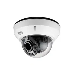
• IR LED
A sensor in the middle monitors lighting levels and
activates the IR LED during low-lighting conditions.
• Lens
A motorized focus and zoom lens is installed.
• Factory Reset Button
Restores the camera's default factory settings. For
more information, refer to the Factory Reset.
• Wall/Ceiling Installation Hole
Used to screw the camera in place on a wall or a
ceiling.
• Power (DC12V)
Connect this to the power adapter.
• Dome Cover Assembly Part
The dome cover will be combined on this part.
• Network Port
Connect a network cable with an RJ-45 connector to
this port. If using a PoE switch, you can supply power
to the camera using an Ethernet cable. For more
information on PoE switch use, refer to the switch
manufacturer's operation manual. You can congure,
manage, and upgrade this camera and monitor its
images from a remote computer over the network.
For more information on network connection setup,
refer to the IDIS Discovery operation manual.
The table below shows the network cable
specications.
<The network cable specications>
Item Content Note
Connector RJ-45
Ethernet 10/100 Base
10/100
Mbps
Cable
UTP Category 5e or
higher
Maximum
length
100m
PoE
IEEE 802.3af, Class 3
• Cable Rubber
Foreign matter may get inside if reconnecting is
failed after removing the cable access hole rubber. A
silicon nish may be required to maintain waterproof
performance. For more information refer to the
Installation part.
• SD Memory Card Slot
Used to insert a micro SD memory card into the
camera. (An SLC (Single Level Cell) or MLC (Multi Level
Cell) card by San Disk or Transcend is recommended.
• To remove/insert the SD memory card or perform
the factory reset, make sure that the lens rear
side's cover is joined properly when screwing it.
Otherwise, the IP66 level is not guaranteed. For
more information, contact your product retailer.
• Do not remove the SD memory card while the
system is in operation. Removing the card while
the system is in operation can cause the system to
malfunction and/or corrupt data stored on the SD
memory card.
• An SD memory card is a consumable product with
a nite service life. Prolonged use will damage
the card's memory sectors and result in data loss
or memory card failure. Test the SD memory card
regularly and replace it whenever necessary.
• Alarm
- O (Out): It is the BJT (Bipolar Junction Transistor)
- open collector output. If the voltage and current
exceed the specication limit (Max. Load: 30mA,
Max. Voltage: 5VDC), the product could be
damaged. When connecting the device which
exceeds the specication limit, refer to the picture
(circuit) below.
If used with an external inductive load(e.g. relay),
a diode must be connected in parallel with the
load for protection. Otherwise, the product could
be damaged.
- I (In): Connect an alarm-in device to this port.
(Mechanism: Choose between an NC (Normally
Closed) type or an NO (Normally Open) type) →
Connect a mechanical or electrical switch to the
alarm in port and the GND (ground) connector.
Alarm in range is 0V to 5V. In order to detect alarm
Loading ...
Loading ...
Loading ...