HEADLAMP BEAM SETTER WITH RAILS
MODEL NO: HBS97.V2
Thank you for purchasing a Sealey product. Manufactured to a high standard, this product will, if used according to these
instructions, and properly maintained, give you years of trouble free performance.
IMPORTANT: PLEASE READ THESE INSTRUCTIONS CAREFULLY. NOTE THE SAFE OPERATIONAL REQUIREMENTS, WARNINGS & CAUTIONS. USE
THE PRODUCT CORRECTLY AND WITH CARE FOR THE PURPOSE FOR WHICH IT IS INTENDED. FAILURE TO DO SO MAY CAUSE DAMAGE AND/OR
PERSONAL INJURY AND WILL INVALIDATE THE WARRANTY. KEEP THESE INSTRUCTIONS SAFE FOR FUTURE USE.
1. SAFETY
8 DO NOT allow unqualified persons to operate this device.
8 DO NOT use this device in direct sunlight.
8 DO NOT splash the unit with water or any other liquid.
9 DO ensure the work area is well ventilated.
9 DO ensure that there is good lighting
9 DO put the handbrake on.
9 DO avoid sudden changes in temperature.
9 DO avoid sudden vibration.
2. INTRODUCTION
DVSA Approved for use in testing stations. Suitable for all types of motorcycles, cars
and light commercial vehicles (Classes: I, II, III, IV, V, VII.). Fixed aiming screen.
Internal analogue LUX meter for accurate light intensity measurement. Supplied with
rails for MOT use. Supplied with instructions and certicate of approval.
3. SPECIFICATION
Model No: ...................................................... HBS97.V2
Focal Length: ...................................................... 489mm
Height: ..............................................................1750mm
Length: ................................................................690mm
Max. Height Beam Measurement: ..................... 1410mm
Min. Height Beam Measurement: ........................240mm
Rail Length: .......................................................2970mm
Width: ..................................................................660mm
HBS97E ....................................1520mm Extension Rail
HBS97ES ................................... 700mm Extension Rail
Optional Accessories: ..................................................
.................................. HBS97E - 1520mm Extension Rail
................................. HBS97ES - 700mm Extension Rail
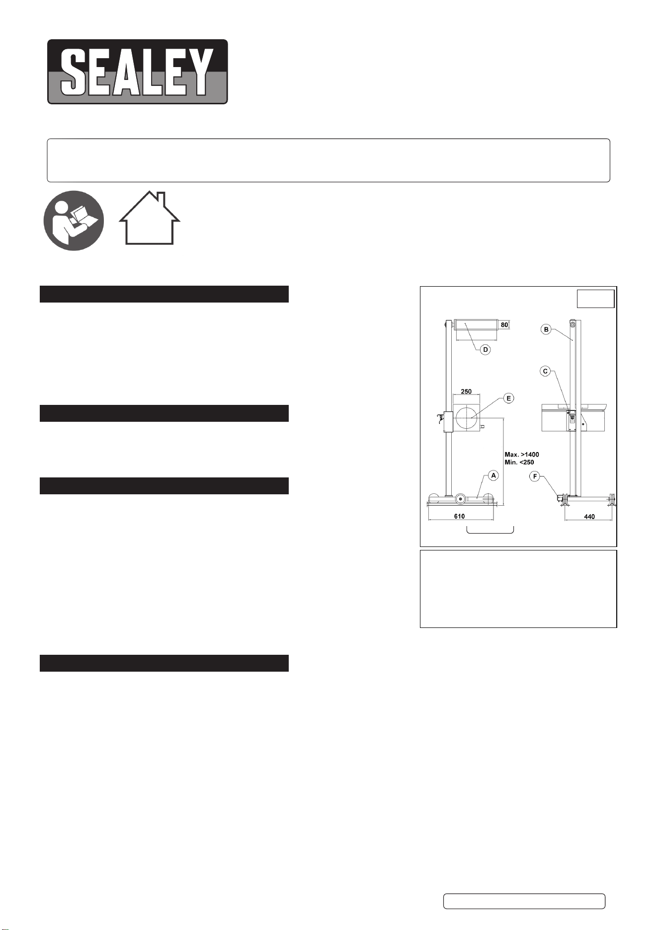
4. ASSEMBLY
4.1. Place large metal washer over spigot at base of column B.
4.2. Insert column spigot into bearing in base A and retain with socket cap bolt and washer provided.
4.3. Attach mirror-visor D to the rotating metal friction plate at the top of the column using the two socket cap bolts provided.
4.4. Fit the optical system E to the vertical - sliding system using an M8 bolt in both the top and bottom holes.
4.5. If the unit is to run on rails these need to be xed to the oor of the test bay with low prole xings that will not interfere with the
movement of the wheels.
4.6. To ascertain the correct positions for the rails place a typical vehicle in the test bay and follow the test procedure without rails. When
the unit is correctly positioned for one headlamp mark the wheel positions on the oor including a longitudinal centre line. Roll the unit
over to the other headlamp, check the alignment, and mark the oor again.
4.7. Place the rails loose on the oor using the markings made and put the unit on them. Roll the unit from one lamp to the other and
recheck the alignment. When satised that all is correct x the rails to the oor.
4.8. HBS97.V2 is approved for class I,II,III and IV as delivered, and by purchasing HBS97E Rail Extensions the unit is also suitable for
Class V, VI,VII. For testing classes I, II, III and IV the rails may be surface mounted. We recommend the rails be recessed into the oor
for all other vehicle testing classes.
Refer to
instructions
For indoor use
only
A - BASE
B - COLUMN
C - VERTICAL SLIDING SYSTEM
D - MIRROR-VISOR
E - OPTICAL SYSTEM
F - COLUMN LOCK PEDAL
FIG.1
Original Language Version
© Jack Sealey Limited
HBS97.V2 Issue 6 (13) 04/03/24
5. PREPARATION FOR USE
5.1. WORKING SURFACE
5.1.1. Position the vehicle on the designated headlamp aim standing area.
5.1.2. When positioning the HBS ensure the floor is perfectly even and level.
5.1.3. If this is not possible the vehicle and HBS must be on the same slope, which must not exceed 0.5º.
5.1.4. Headlights must not be checked where surfaces exceed 0.5º angle. (See fig.2).
5.2. VEHICLE PREPARATION
5.2.1. Straighten vehicle wheels.
5.2.2. Check the tyre pressure.
5.2.3. Ensure the headlights are clean and dry.
5.2.4. If the vehicle is fitted with manual or electric headlamp levelling devices, ensure these are set up for vehicle with normal load.
5.2.5. Remove anything which could alter the vehicles position, i.e. Snow, Ice, Mud, etc.
6. OPTICAL POSITIONING
FIG.3 FIG.4
6.1. POSITIONING
Conventional, Double Ellipsoid (DE) Headlamps
Locate the HBS approximately 200 to 500mm from the vehicle headlamp.
Gas Discharge (Xenon) and Free Form (FF) Headlamps
Locate the HBS as close to the headlamp lens as possible.
Close proximity between the lens and the HBS gives a more dened light/dark margin on the aiming screen enabling accurate
alignment.
6.1.1. Use the visor to align with a horizontal, or two symmetrical points on the vehicle (g.4) i.e. The bonnet lip or the bottom of the
windscreen.
6.1.2. Ensure the visor lines match with your horizontal, or symmetrical selection, to ensure the HBS is parallel to the headlamp.
6.1.3. Measure the height from the oor to the centre of the headlight e.g.80cm. Release the HBS unit by squeezing the lower lever upwards
as shown in g.3. Slide the unit up or down the column as required until the top surface of the sliding portion is aligned with 80 on the
scale printed on the column shown in g.3A. Release the locking lever. There is a tolerance level of 30mm.
6.2. HBS COLUMN ROTATION LOCK
The HBS system is tted with a rotating column and is suitable for use either on or o rails. If you are using the system on rails then
the rotating column aids correct alignment. To release the column lock put pressure on the foot pedal in an anticlockwise direction as
shown in g 5. To re-lock the column put pressure on the foot pedal in a clockwise direction as shown in g.6.
FIG.5 FIG.6
7. METHOD OF INSPECTION
7.1. Switch engine on.
7.2. Align the headlamp aim equipment with the longitudinal axis of the vehicle.
7.3. Align the centre of the collecting lens with the centre of the headlamp under test.
OK
0.5
0
MAX
NO
NO
FIG.2
Original Language Version
© Jack Sealey Limited
HBS97.V2 Issue 6 (13) 04/03/24
7.4. With an assistant sitting in the driving seat, switch on the headlamps to the beam on which the headlamp is to be checked.
Note: When checking headlamp aim on vehicles with hydropneumatic suspension systems, it is necessary to have the engine idling.
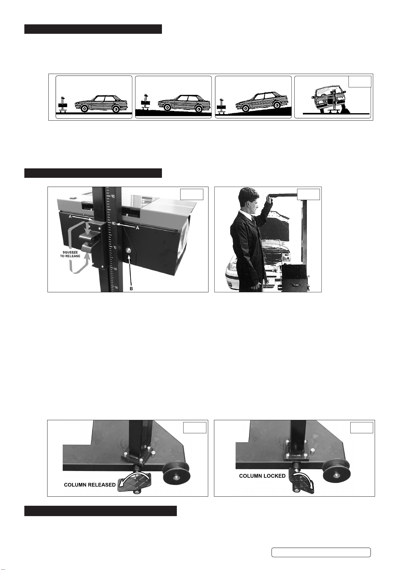
7.5. Determine the appropriate headlamp beam image and its aim (see fig 7.). Old vehicles (approx. pre 1950 ) headlamps beam image may
not conform to fig 7, in such cases check:
a) DIP BEAM headlamps are aimed so they DO NOT dazzle i.e. the beam image brightest part is aimed at least 0.5% below
the horizontal (fig 8). Or, for headlamps which cannot be checked on dip beam, check:
b) MAIN BEAM headlamps are aimed so that the beam image centre is on or slightly below the horizontal (fig 9).
8. GRADUATED SCREEN
FIG.7
IMPORTANT
The HBS system uses a fixed graduated
screen in accordance with the requirements
of the MOT regulations.
CORRECT LIGHT PROJECTION ON THE LINE 0.5% (BEAM LIGHT)
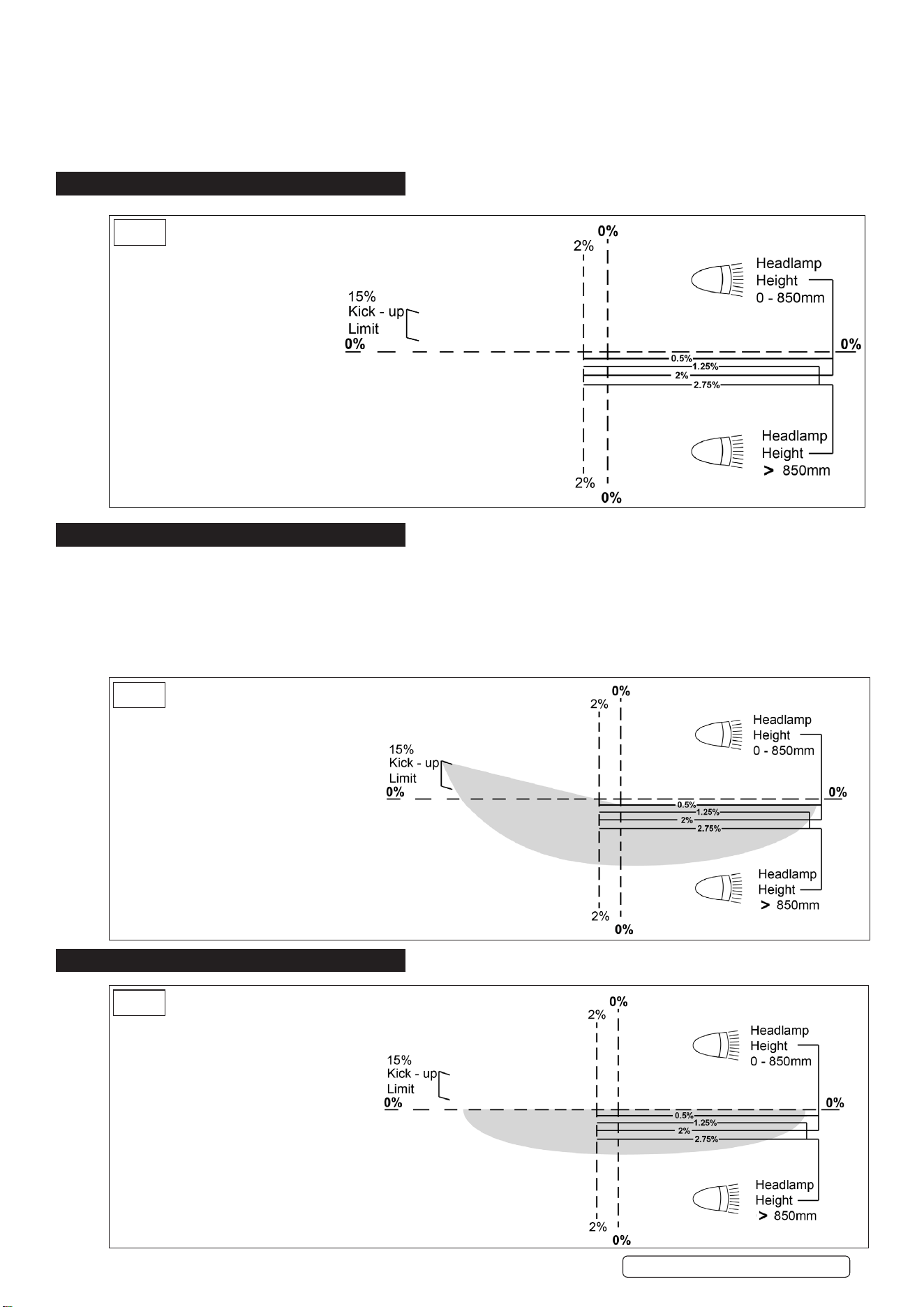
9. DIPPED BEAM
9.1. Prepare the HBS and the car as previously instructed, then turn on the dipped beam.
9.2. Check the headlamp beam tolerances are in accordance with MOT inspection manual, and are within operating tolerances of
manufacturer’s guidelines.
9.3. Adjust the vehicles light regulating system until you obtain the required result.
9.4. When testing the more commonly used asymmetrical headlight (see fig 7), remember that their projection will light up a section on the
LEFT hand side of the plate with a corner of about 15
0
from the horizontal plane. Just under the centre, on the right, a small zone will
appear brighter than the rest of the projection.
*
FIG.8
Correct projection on panel.
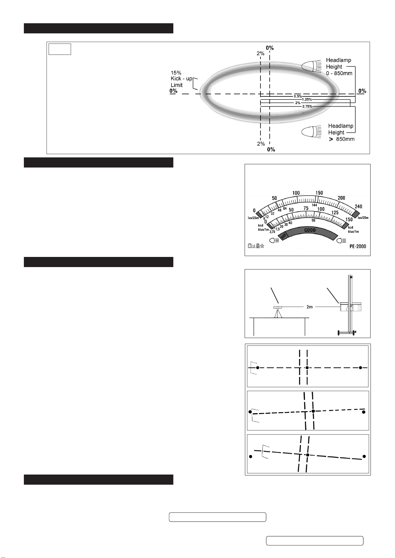
10. SYMMETRICAL LIGHTS
FIG.9
When testing symmetrical low light beams the
projection on the plate will describe a perfect
horizontal line.
*
Original Language Version
© Jack Sealey Limited
HBS97.V2 Issue 6 (13) 04/03/24
11. INDEPENDENT HEADLIGHTS
It is necessary to obtain a strong bright zone at the
centre of the plate, where the black spot is located.
FIG.10
12. THE LUXMETER
12.1. Indicator at BAD/GOOD limit:
Use for vehicles travelling under 30mph (40Km/h) and motorbikes.
12.2. Indicator at the centre of GOOD:
Use for vehicles travelling over 30mph (40Km/h)
12.3. CONTROL OF THE HEADLAMP LIGHT INTENSITY
a) Switch on the headlamp main beam. b) Read the intensity on the luxmeter.
13. CALIBRATION
13.1. We suggest the unit is periodically checked for calibration in situ. If the unit
is covered by a service agreement with the MOT package installer, they will
carry this out on your behalf. Should you wish to regularly check the calibration
yourself, we recommend you purchase an Alignment Device from your local
stockist.
13.2. Periodical calibration of the relationship between the test area and the aiming
screen is required. For the purposes of calibration, it is assumed that the vehicle
standing area is at and level.
13.3. Place the calibration gauge within the vehicle standing area.
13.4. Switch on the laser and ensure the beam is at and level by use of the integral
spirit level.
13.5. Check that the optical box is at and level by checking the spirit level in the base
of the optical box. The spirit level may be viewed through the plexiglass cover.
Adjust the pitch of the optical box by loosening the screw (See g.3B). Ensure
screw is re-tightened after adjustment.
13.6. Project the laser beam through the lens of the optical box. There is a Ø30mm
margin for error in alignment of the beam centrally through the lens.
13.7. Align the projected red dot centrally on the screen. The dot should fall on the
hatched 0% line.
13.8. Move the screen left and right across the beam by rotating the column and
ensure the dot remains on the 0% line indicating that the aiming screen is level.
13.9. If adjustment of the aiming screen is required;
13.10. Undo the four screws which retain the plexiglass cover and remove it.
13.11. Loosen the two screws which retain the aiming screen.
13.12. Adjust aiming screen so that laser dot falls on 0% line.
13.13. Retighten screws and replace cover.
13.14. Once calibration has been completed the serial numbers of the HBS and the
calibration device used to complete the calibration should be recorded on a
suitable document. This document should be retained for inspection if required.
14. MAINTENANCE
14.1. The paint work is detergent resistant. Clean with a damp cloth, removing any stains. A small amount of alcohol may be applied to stubborn
areas of grime.
8 DO NOT leave the machine in areas where corrosive vapour is present, i.e. Battery charging or painting shops etc.
8 DO NOT oil the column.
Alignment OK
Adjust screen
Adjust screen
The “Luxmeter” is colour graduated for clear
reading as follows:
Original Language Version
© Jack Sealey Limited
Laser device
Beam setter lens
HBS97.V2 Issue 6 (13) 04/03/24
HBS97.V2 Issue 6 (13) 04/03/24

Original Language Version
© Jack Sealey Limited
HBS97.V2 Issue 6 (13) 04/03/24
Sealey Group, Kempson Way, Suffolk Business Park, Bury St Edmunds, Suffolk. IP32 7AR
01284 757500 sales@sealey.co.uk www.sealey.co.uk
ENVIRONMENT PROTECTION
Recycle unwanted materials instead of disposing of them as waste. All tools, accessories and packaging should be sorted,
taken to a recycling centre and disposed of in a manner which is compatible with the environment. When the product
becomes completely unserviceable and requires disposal, drain any fluids (if applicable) into approved containers and
dispose of the product and fluids according to local regulations.
REGISTER YOUR
PURCHASE HERE
Note: It is our policy to continually improve products and as such we reserve the right to alter data, specications and component parts
without prior notice. Please note that other versions of this product are available. If you require documentation for alternative versions, please
email or call our technical team on technical@sealey.co.uk or 01284 757505.
Important: No Liability is accepted for incorrect use of this product.
Warranty: Guarantee is 12 months from purchase date, proof of which is required for any claim.