Loading ...
Loading ...
Loading ...
17
With power disconnected, operate the blade tilt and height
adjustments through the extremes of travel to be sure the
blade guard assembly clears the blade in all operations and
that the anti-kickback assembly is functioning.
ALIGNING RIVING KNIFE TO BLADE
1. Remove the throat plate, blade guard and anti-
kickback assemblies.
2. Raise the blade to full depth of cut and 0° bevel angle.
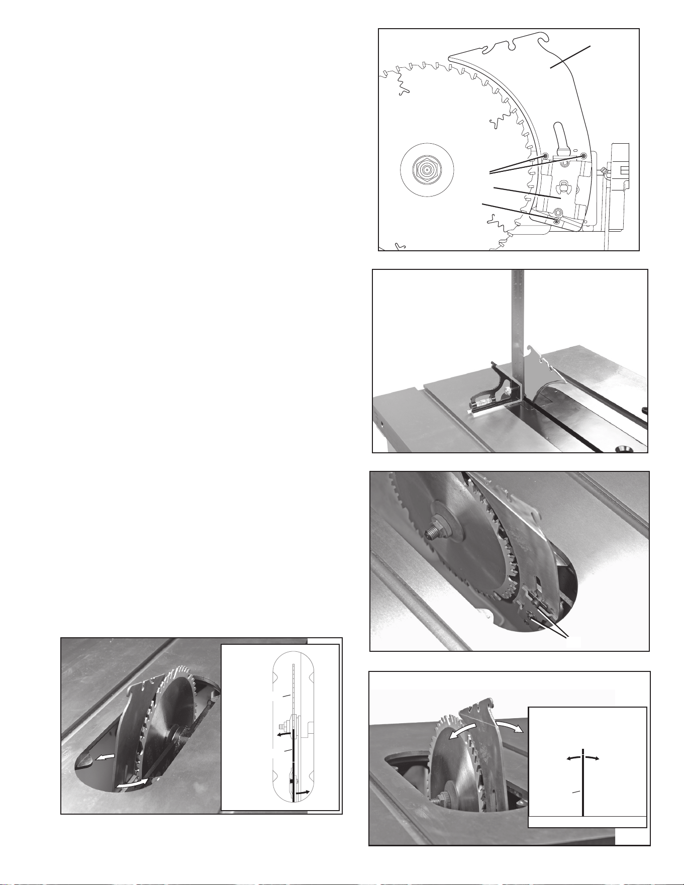
3. Raise the riving knife (J) Fig. 33 to the through-cutting
or highest position (Fig. 27).
4. Locate the three small set screws (PP) and (QQ)
adjacent to the riving knife locking plate (RR). These
screws will be used to adjust the riving knife position.
5. Lay a straight edge on the table against blade body
and make sure it extends out along the riving knife,
as shown in Fig. 32. The riving knife should just touch
the straight edge. If adjustment needed, loosen the
two socket head cap screws (SS) Fig. 35.
6. Adjust the set screws (PP) and (QQ) Fig. 33 to move
the riving knife in line with the blade according to
the position noted in STEP 5. Lay the straight edge
on the opposite side of the blade and repeat these
adjustments as needed.
NOTE: The two set screws (PP) near the riving knife
locking plate (RR) adjust the riving knife as shown from
the TOP VIEW (Fig. 36). The set screw (QQ) adjusts the
riving knife as shown from the BACK OF TABLE VIEW
(Fig. 37).
7. Lightly tighten the two socket head cap screws (SS)
Fig. 35.
8. Place a square flat against the riving knife and verify
riving knife is vertical and in-line with the blade.
(Fig. 34)
9. If needed, use the set screws to bring the riving knife
vertical with the square.
10. Repeat STEPS 5 and 6 to verify position of riving
knife.
11. Fully tighten the two socket head cap screws (SS)
Fig. 35.
12. Replace throat plate before use.
FIG. 33
FIG. 35
FIG. 37
J
PP
QQ
RR
SS
Blade
TOP VIEW
Top two screws
make this
adjustment
Riving Knife
Table
BACK OF TABLE VIEW
Bottom screw
makes this
adjustment
Riving Knife
FIG. 36
FIG. 34
Loading ...
Loading ...
Loading ...