
1
Quick Guide
SHA800A
Spectrum &
Network Analyzer
Quick Guide
EN_01A


SHA800A QuickGuide I
Guaranty and Declaration
Copyright
SIGLENT TECHNOLOGIES CO., LTD All Rights Reserved.
Trademark Information
SIGLENT
®
is the registered trademark of SIGLENT TECHNOLOGIES CO., LTD.
Declaration
⚫ SIGLENT products are protected by patent law worldwide.
⚫ SIGLENT reserves the right to modify or change parts of or all the
specifications or pricing policies at company’s sole decision.
⚫ Information in this publication replaces all previous corresponding material.
⚫ Any way of copying, extracting or translating the contents of this manual is not
allowed without the permission of SIGLENT.
⚫ SIGLENT will not be responsible for losses caused by either incidental or
consequential in connection with the furnishing, use or performance of this
manual as well as any information contained.
Product Certification
SIGLENT guarantees this product conforms to the national and industrial
standards in China as well as the ISO9001: 2008 standard and the ISO14001:
2004 standard. Other international standard conformance certification is in
progress.

II SHA800A QuickGuide
Contents
Guaranty and Declaration ............................................................................. I
Contents ...................................................................................................... II
Important Safety Information ....................................................................... 1
Safety Compliance....................................................................................... 8
General Inspection....................................................................................... 9
Preparing for Use....................................................................................... 10
Firmware Operation ................................................................................... 23
Remote Control.......................................................................................... 25
Service and Support .................................................................................. 25
Troubleshooting ......................................................................................... 26

SHA800A QuickGuide 1
Important Safety Information
This manual contains information and warnings that must be followed by the user
for safe operation and to keep the product in a safe condition.
General Safety Summary
Carefully read the following safety precautions to avoid any personal injury or
damage to the instrument and any products connected to it. To avoid potential
hazards, please use the instrument as specified.
To Avoid Fire or Personal Injury
Use Proper AC Power Line
Only the power cord designed for the instrument and authorized by local country
should be used.
Ground the Instrument
The instrument is grounded through the protective earth conductor of the power
line. To avoid electric shock, please make sure the instrument is grounded correctly
before connecting its input or output terminals.
Look Over All Terminals’ Ratings
To avoid fire or electric shock, please look over all ratings and sign instructions of
the instrument. Before connecting the instrument, please read the manual carefully
to gain more information about the ratings.
Equipment Maintenance and Service
When the equipment fails, please do not dismantle the machine for maintenance.
The equipment contains capacitors, power supply, transformers, and other energy
storage devices, which may cause high voltage damage. The internal devices of
the equipment are sensitive to static electricity, and direct contact is easy to cause
irreparable damage to the equipment. It is necessary to return to the factory or the
company's designated maintenance organization for maintenance.
Be sure to pull out the power supply when repairing the equipment. Live line
operation is strictly prohibited. The equipment can only be powered on when the
maintenance is completed and the maintenance is confirmed to be successful.

2 SHA800A QuickGuide
Identification of Normal State of Equipment
After the equipment is started, there will be no alarm information and error
information at the interface under normal conditions. The curve on screen will scan
from left to right freely; if there is a button in the scanning process or is an alarm or
error prompt, the device may be in an abnormal state. You need to view the specific
prompt information. You can try to restart the setting. If the fault information is still in
place, do not use it for testing. Contact the manufacturer or the maintenance
department designated by the manufacturer to carry out maintenance to avoid
sabotage data by fault operations or endanger the personal safety.
Not Operate with Suspected Failures
If you suspect that there is damage to the instrument, please let qualified service
personnel check it.
Avoid Circuit or Wire Components Exposed
Do not touch exposed connectors or components when the power is on.
Do not operate in wet/damp conditions
Do not operate in an explosive atmosphere
Keep the surface of the instrument clean and dry
Not to use the equipment for measurements on mains circuits, not to use the
equipment for measurements on voltage over the voltage range described in
the manual. The maximum additional transient voltage cannot exceed 1300V.
The responsible body or operator should refer to the instruction manual to
preserve the protection afforded by the equipment. If the equipment is used
in a manner not specified by the manufacturer, the protection provided by the
equipment may be impaired.
Any parts of the device and its accessories are not allowed to be changed or
replaced, other than authorized by the manufacturer or agent.
SHA800A QuickGuide 3
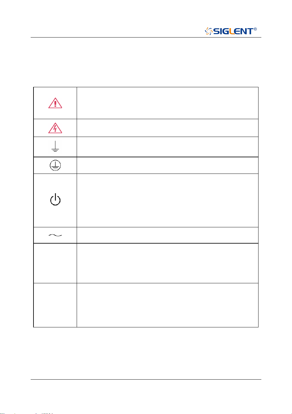
Safety Terms and Symbols
When the following symbols or terms appear on the front or rear panel of the
instrument or in this manual, they indicate special care in terms of safety.
This symbol is used where caution is required. Refer to the
accompanying information or documents to protect against
personal injury or damage to the instrument.
This symbol warns of a potential risk of shock hazard.
This symbol is used to denote the measurement ground
connection.
This symbol is used to denote a safety ground connection.
This symbol shows that the switch is an On/Standby switch.
When it is pressed, the analyzer’s state switches between
Operation and Standby. This switch does not disconnect the
device's power supply. To completely power off the analyzer,
the power cord must be unplugged from the AC socket after
the instrument is in the standby state.
This symbol is used to represent alternating current, or “AC”.
CAUTION
The “CAUTION” symbol indicates a potential hazard. It calls
attention to a procedure, practice, or condition which may be
dangerous if not followed. Do not proceed until its conditions
are fully understood and met.
WARNING
The “WARNING” symbol indicates a potential hazard. It calls
attention to a procedure, practice, or condition which, if not
followed, could cause bodily injury or death. If a WARNING is
indicated, do not proceed until the safety conditions are fully
understood and met.
4 SHA800A QuickGuide
Working Environment
The design of the instrument has been verified to conform to EN 61010-1 safety
standard per the following limits:
Environment
The instrument is used indoors and should be operated in a clean and dry
environment with an ambient temperature range.
Note: Direct sunlight, electric heaters, and other heat sources should be
considered when evaluating the ambient temperature.
Warning: Do not operate the instrument in explosive, dusty or humid
environments.
Ambient Temperature
Operating: 0
℃
to +50
℃
Non-operation: -30
℃
to +70
℃
Note: Direct sunlight, radiators, and other heat sources should be considered when
assessing the ambient temperature.
Humidity
Operating: 5% ~ 90 %RH, 30
℃
, derate to 50 %RH at 40
℃
Non-operating: 5% ~ 95% RH
Altitude
Operating: ≤ 3,000 m, 25
℃
Non-operating: ≤ 12,000 m
SHA800A QuickGuide 5
Installation (overvoltage) Category
This product is powered by mains conforming to installation (overvoltage) Category
II.
Note: Installation (overvoltage) category I refers to situations where equipment
measurement terminals are connected to the source circuit. In these terminals,
precautions are done to limit the transient voltage to a correspondingly low level.
Installation (overvoltage) category II refers to the local power distribution level
which applies to equipment connected to the AC line (AC power).
Degree of Pollution
The analyzers may be operated in environments of Pollution Degree II.
Note: Degree of Pollution II refers to a working environment where dry and
non-conductive pollution occurs. Occasional temporary conductivity caused by
condensation is expected.
IP Rating
IP20 (as defined in IEC 60529).
Cooling Requirements
This instrument relies on the forced air cooling with internal fans and ventilation
openings. Care must be taken to avoid restricting the airflow around the apertures
(fan holes) at each side of the analyzer. To ensure adequate ventilation it is
required to leave a 15 cm (6 inch) minimum gap around the sides of the instrument.
CAUTION: Do not block the ventilation holes located on both sides
of the analyzer.
CAUTION: Do not allow any foreign matter to enter the analyzer
through the ventilation holes, etc.
6 SHA800A QuickGuide
Power and Grounding Requirements
The instrument operates with a single-phase, 100 to 240 Vrms (+/-10%) AC power
at 50/60 Hz (+/-5%), or single-phase 100 to 120 Vrms (+/-10%) AC power at 400 Hz
(+/-5%).
No manual voltage selection is required because the instrument automatically
adapts to line voltage.
Depending on the type and number of options and accessories (probes, PC port
plug-in, etc.), the instrument can consume up to 193 W of power.
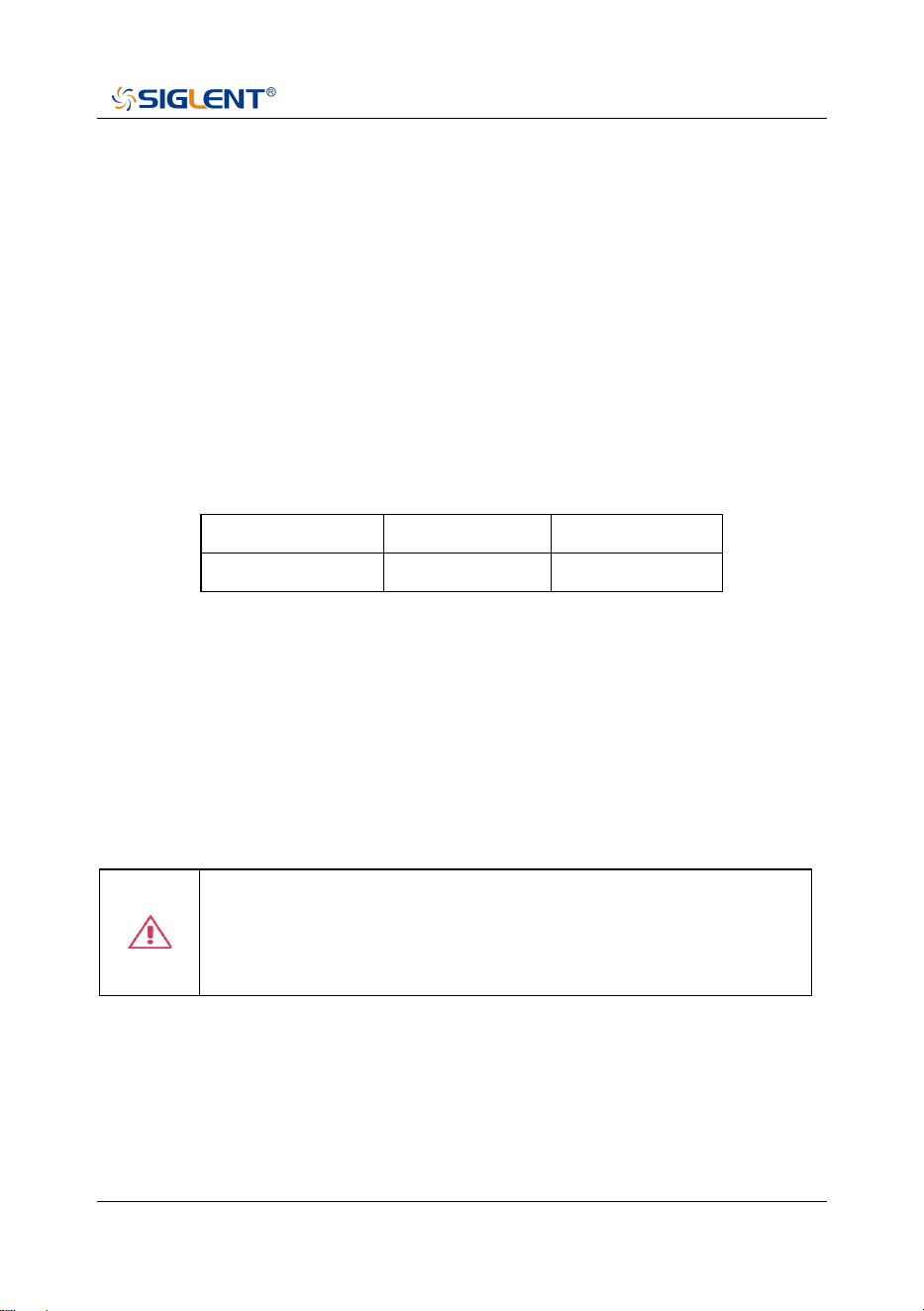
Note: The instrument automatically adapts to the AC line input within the following
ranges:
Voltage Range:
90 - 264 Vrms
90 - 132 Vrms
Frequency Range:
47 - 63 Hz
380 - 420 Hz
The instrument includes a grounded cord set containing a molded three-terminal
polarized plug and a standard IEC320 (Type C13) connector for making line
voltage and safety ground connection. The AC inlet ground terminal is connected
directly to the frame of the instrument. For adequate protection against electrical
shock hazards, the power cord plug must be inserted into a mating AC outlet
containing a safety ground contact. Use only the power cord specified for this
instrument and certified for the country of use.
Warning: Electrical Shock Hazard!
Any interruption of the protective conductor inside or outside of the
analyzer, or disconnection of the safety ground terminal creates a
hazardous situation. Intentional interruption is prohibited.
The position of the instrument should allow easy access to the socket. To make the
instrument completely power off, unplug the instrument power cord from the AC
socket.
SHA800A QuickGuide 7
The power cord should be unplugged from the AC outlet if the analyzer is not to be
used for a long time.
CAUTION: The outer shells of the front panel terminals are
connected to the instrument’s chassis and therefore to the safety
ground.
Cleaning
Clean only the exterior of the instrument, using a damp, soft cloth. Do not use
chemicals or abrasive elements. Under no circumstances allow moisture to
penetrate the instrument. To avoid electrical shock, unplug the power cord from the
AC outlet before cleaning.
Warning: Electrical Shock Hazard!
No operator serviceable parts inside. Do not remove covers.
Refer servicing to qualified personnel.
Abnormal Conditions
Do not operate the analyzer if there is any visible sign of damage or has been
subjected to severe transport stresses.
If you suspect the analyzer’s protection has been impaired, disconnect the power
cord and secure the instrument against any unintended operation.
Proper use of the instrument depends on careful reading of all instructions and
labels.
Warning: Any use of the analyzer in a manner not specified by the
manufacturer may impair the instrument’s safety protection. This
instrument should not be directly connected to human subjects or
used for patient testing.

8 SHA800A QuickGuide
Safety Compliance
U.S. nationally recognized testing laboratory listing
1. UL 61010-1:2012/R: 2018-11. Safety Requirements for Electrical
Equipment for Measurement, Control, and Laboratory Use – Part 1:
General Requirements.
2. UL 61010-2-030:2018. Safety Requirements for Electrical Equipment for
Measurement, Control, and Laboratory Use – Part2-030: Particular
requirements for testing and measuring circuits.
Canadian certification
1. CAN/CSA-C22.2 No. 61010-1:2012/A1:2018-11. Safety Requirements
for Electrical Equipment for Measurement, Control, and Laboratory Use –
Part 1: General Requirements.
2. CAN/CSA-C22.2 No. 61010-2-030:2018. Safety Requirements for
Electrical Equipment for Measurement, Control, and Laboratory Use –
Part 2 - 030: Particular requirements for testing and measuring circuits.

SHA800A QuickGuide 9
General Inspection
Inspect the shipping container
Keep the damaged shipping container or cushioning material until the contents of
the shipment have been completely checked and the instrument has passed both
electrical and mechanical tests.
The consigner or carrier will be responsible for damages to the instrument resulting
from shipment. SIGLENT will not provide free maintenance or replacement.
Inspect the instrument
If the instrument is found to be damaged, defective or fails in electrical or
mechanical tests, please contact SIGLENT.
Check the accessories
Please check the accessories according to the packing list. If the accessories are
incomplete or damaged, please contact your SIGLENT sales representative.
10 SHA800A QuickGuide
Preparing for Use
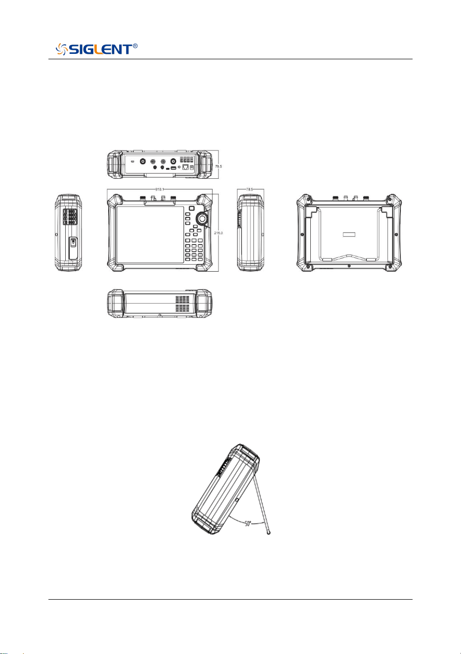
Appearance and Dimension
Front and lateral View
The included tilting stand is available for desktop operation. The tilting bracket
provides a backward tilt for improved stability. To deploy the tilt bracket, pull the
bottom of the tilt bracket away from the back of the instrument. To retract the tilting
bracket, push the bottom of the bracket toward the back of the instrument.
Side View
Unit
:
mm

SHA800A QuickGuide 11
Power Supply Information
The battery that comes with the SHA800A may need to be recharged before use.
The device can use the supplied AC-DC adapter (refer to the product technical data
sheet for ordering information). The specifications of the input AC power supply are:
100-240V, 50/60Hz; Or charge through the on-board DC adapter in the accessory.
Specifically, the analyzer can be connected to the adapter according to the power
socket shown in the figure below.
Rear View and Power
◆ Adapter factory configuration is the 12V 4A
◆ Battery factory installed, the user can change itself
WARNING
This instrument can only use Siglent approved batteries, adapters
and chargers. When using an onboard DC adapter, always ensure
that the power supply is rated at least 75 W @ 15 VDC and that
there is no dust or debris on the socket. If the adapter plug
becomes hot during operation, discontinue use immediately.
Siglent recommends taking out the batteries when devices aren't
used for too long.
Power socket
12 SHA800A QuickGuide
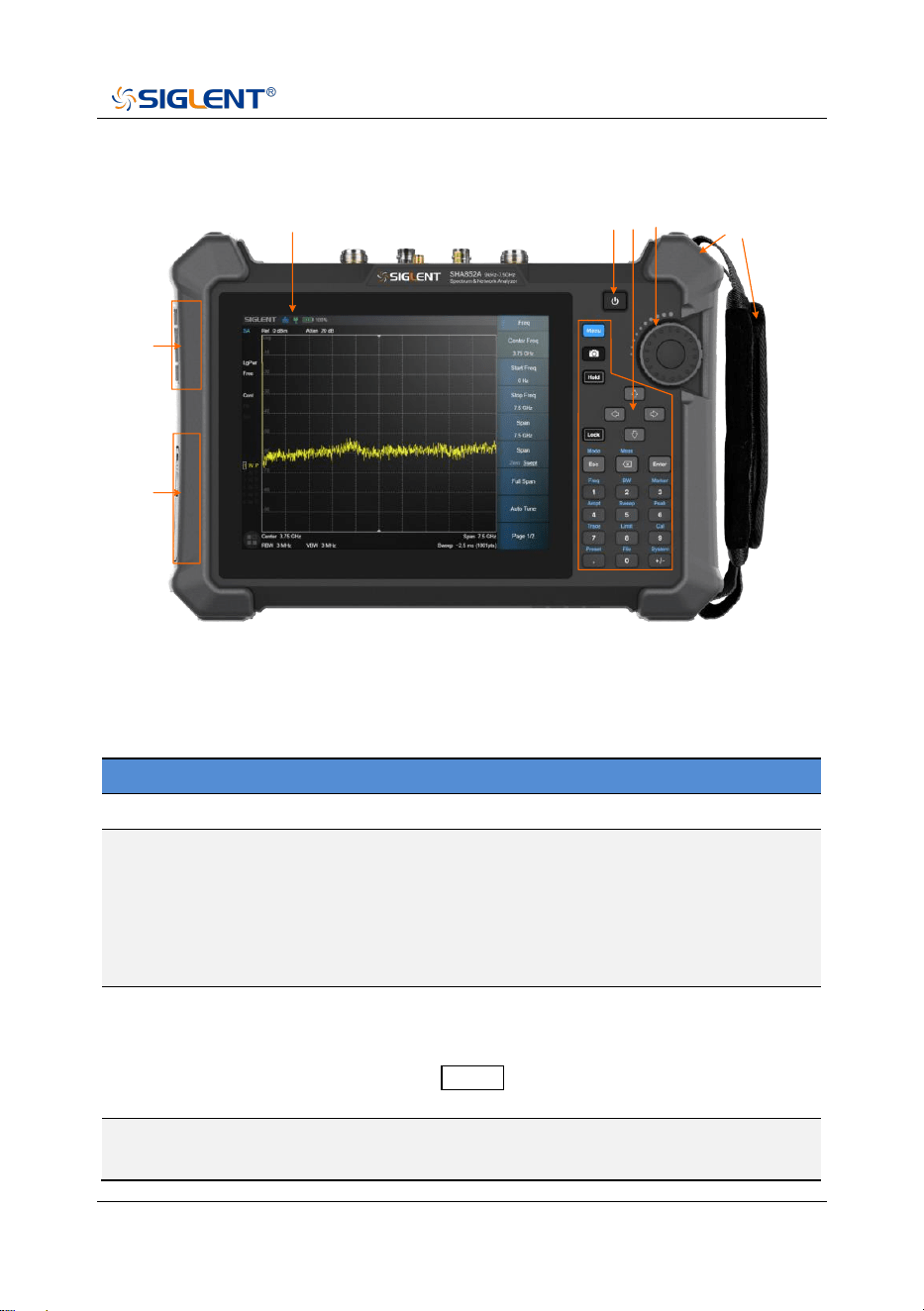
Front Panel
1
2 3 4
5
6
7
The Front Panel
Front Panel Description
NO.
Name
Description
1
LCD Screen
8.4 inch multi-touch screen, resolution 800*600
2
Power Switch
Stand by status: Orange
Power on status: White
Short press: To Stand by status with current
state saved
Long press: To Stand by status without current
state saved
3
Function Keys
Complete the function control and parameter
input of the analyzer, and most operations can
be completed by the touch screen.
Press Lock to turn off/on the keyboard and
touch functions.
4
Three-dimensional
knob
Complete the quick adjustment and selection of
parameters.
SHA800A QuickGuide 13
5
Fan vent
Built-in fan external exhaust port. Please ensure
that this vent is unblocked.
6
Battery case cover
Internal battery protection cover. Remove during
battery replacement.
7
Detachable
hand strap
Convenient hand force, can be installed on both
sides.
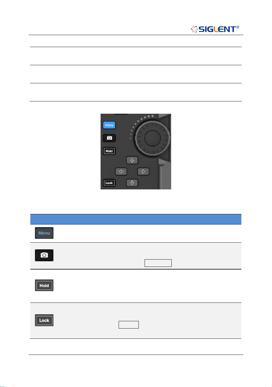
Shorcut Keys Description
Name
Description
The menu selection window pops up on the screen, and you can
use the touch screen control to directly enter a function menu.
Shortcut screenshot button to save the current screen display as
a picture. Save parameters, such as path, reverse color, and
screenshot area, to be set in System > File .
Measurement control, pause or resume the current measurement
process. When the button light is on, the measurement is
suspended. When the button light is off, the measurement is
resumed.
Key and touch screen lock control.
When the button light is on, all key pad buttons and touch screen
buttons except the Lock button are locked to prevent
misoperation.
14 SHA800A QuickGuide
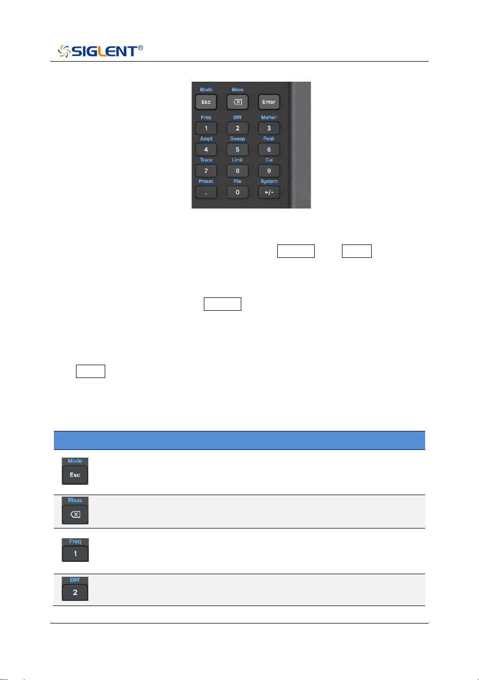
The function key part of the front panel is the reuse key of menu selection mode
and value input mode, which can be switched by Enter and Esc :
◆ Under default reset, the operation interface is in menu selection mode, and
function keys will be identified as the blue silk screen function identifier on the
upper side of the key. Use Enter to switch from menu selection mode to
value input mode.
◆ When the operation interface is in value input mode, the multiplex key will be
identified as the white silk screen digital identifier inside the key. You can use
Esc to switch from value input mode to menu selection mode.
Function Keys Description
Name
Description
Menu selection mode, to select the analyzer operation mode,
such as spectrum analysis mode, antenna and cable test mode,
network analyzer mode, etc.
In menu selection mode, control of mode measurement
parameters, such as average times, specific test items, etc.
In menu selection mode, frequency parameters are controlled. In
time domain analysis, length (distance) parameters are
controlled.
Menu selection mode, bandwidth class parameter control, such
as RBW, VBW, IFBW and so on.
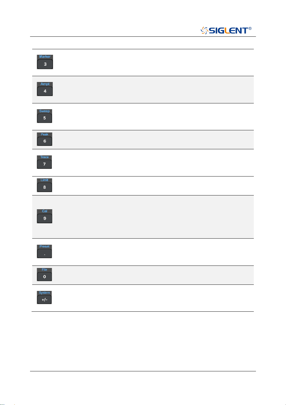
SHA800A QuickGuide 15
In menu selection mode, control cursor Marker parameters, such
as cursor type, cursor positioning, noise cursor, N dB bandwidth,
etc.
Menu selection mode, for amplitude class parameters control,
such as scale and unit, as well as preattenuator, preamplifier,
amplitude correction, etc.
In the menu selection mode, control the scanning parameters,
such as scanning time and type, scanning number, trigger,
gating, etc.
In the menu selection mode, control the peak parameters, such
as peak search, peak rule setting, etc.
In menu selection mode, trace parameters are controlled, such
as trace state, detection, mathematical calculation,
normalization, etc.
In menu selection mode, control the parameters of limit line,
such as limit line editing, margin, test state setting, etc.
In menu selection mode, port calibration of antenna and cable
test mode and network analysis mode is carried out, such as
selecting the type of mechanical calibration part, user-defined
calibration part parameters, loading electronic calibration part,
etc.
In menu selection mode, reset parameters can be controlled,
such as reset status definition, power-on status definition, user
status definition, etc.
In the menu selection mode, you can perform file operations,
such as saving and invoking files, and viewing file browsers.
In menu selection mode, the system general information view,
version and calibration operation, as well as input and output
port Settings, screen display Settings, etc.
16 SHA800A QuickGuide
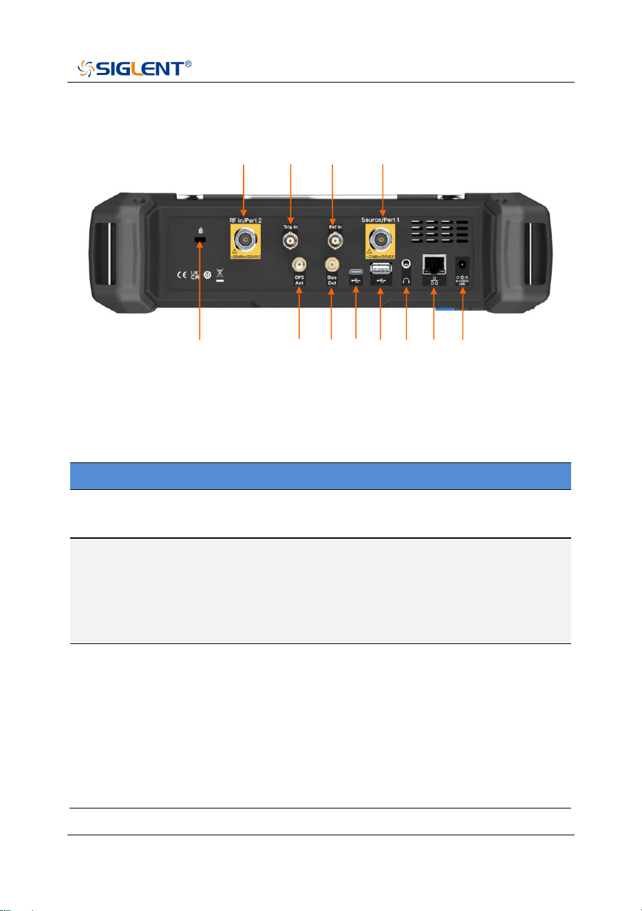
Rear Panel
1
2
4
5
6
8
9
10 11 12
3
7
Rear Panel
Rear Panel Description
NO.
Name
Description
1
RF In/Port 2
Signal input: 50Ω N female connector.
Maximum input ±50 VDC, + 30 dBm.
2
Trig In
Trigger input is a BNC female connector. When the
analyzer uses an external trigger mode, the
connector receives a rising or falling edge of an
external trigger signal that is used to establish event
synchronization.
3
Ref In
Reference clock input, BNC female connector. The
analyzer can use an internal reference clock or an
external reference clock. If the instrument detects a
signal from an external 10 MHz reference clock, it
automatically uses the signal as the analyzer's
reference clock source. At this time the screen status
bar frequency reference display external;
When the external 10 MHz reference signal is lost,
SHA800A QuickGuide 17
exceeded, or not connected, the analyzer's reference
clock is automatically switched to the internal 10 MHz
reference clock, and the screen frequency reference
bar will display the internal.
[Ref In] is used to establish clock synchronization
between multiple instruments.
4
Source/Port 1
The signal output and input terminals are 50Ω N
female connectors.
In spectrum analysis mode, signal output as an
independent signal source.
In the network analysis mode, as the excitation and
receiving interface, this port built-in coupler, to
achieve a single port vector network analysis
function.
5
K-groove
Slots are provided to accept Kensignton® cable
locks.
6
GPS Ant
The GPS antenna port is a SMA female connector
used to install the GPS antenna and receive GPS
satellite signals.
Can provide 3.3V DC feed for active GPS antenna.
7
Bias Out
The offset voltage output port is a 50
Ω
female SMB
connector.
Used to provide bias voltage for external signal
amplifiers, such as tower amplifiers.
8
USB Device
The main USB port is TypeC. The analyzer can be
used as a slave device and connected to a PC via
USB cable. The PC uses the USB-TMC protocol to
remotely control the analyzer.
9
USB Host
USB slave port, TypeB. The analyzer can be used as
the main device and is connected to external USB
devices through this port. For example,
Connect external extended memory to read files in
memory, or store the current instrument state, data,

18 SHA800A QuickGuide
or current screen display content into memory;
Connect a USB keyboard, USB mouse, or other USB
receiver; Connect USB-GPIB adapter to realize GPIB
remote control of analyzer;
Connect electronic calibration parts to realize
automatic calibration of analyzer.
10
Audio output
3.5mm headphone jack. The analyzer provides AM
and FM demodulation functions.
The headphone jack is used to insert the headphone
to listen to the audio output of the demodulation
signal. You can turn on or off the headset and adjust
the volume of the headset through the menu.
11
LAN
RJ45 ports. The analyzer is connected to the LAN
through network cable, and can be viewed and
controlled remotely through VXI, Socket protocol, or a
web browser.
12
External
power supply
2.5mm x 5.5mm barrel connector, connected to 12V
4A power adapter charging port, center positive.
Used to power devices and charge batteries.
SHA800A QuickGuide 19
WARNING
The analyzer does not support DC input. To avoid damage to the
instrument, the DC voltage component of the signal reaching the RF
input must not exceed 50 V.
If possible, add an isolated DC component to the RF input of the
analyzer before signal measurement.
WARNING
In order to avoid damage to the instrument, the DC voltage
component of the signal input to the RF input should not exceed
50 V;
When the frequency is greater than 10 MHz, the maximum
continuous power of the RF signal shall not exceed +33 dBm.
When the frequency is less than 10 MHz, the maximum continuous
power of the RF signal should not exceed +20 dBm.
WARNING
Before connecting any signal, short connect the inner core of the
test cable to the housing floor to release the static electricity
accumulated on the inner core of the test cable.
20 SHA800A QuickGuide
User Interface
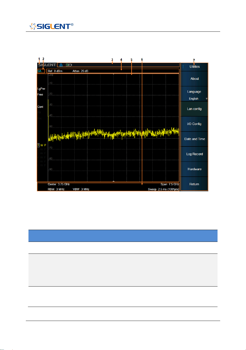
User Interface of spectrum analyzer mode
Spectrum Analyzer Mode User Interface
NO.
Name
Description
1
SIGLENT
SIGLENT logo
2
Mode/
Measure
Indicate the current working mode and
measurement function of the analyzer, and click to
switch, such as spectrum analysis mode, real-time
spectrum mode, etc.
3
Hardware
status bar
Indicates the status of hardware, interfaces, etc.
SHA800A QuickGuide 21
4
Measurement
status bar
Indicates measurement status of reference level,
attenuation, cursor, etc.
5
Result
display area
The measurement results are displayed in various
forms such as spectral lines, cursors, tables and
constellation charts.
6
Scan
parameter
area
Indicates and controls major scan parameters.
7
Menu area
Used to configure measurement Settings.
Touch screen and mouse operation
The analyzer provides a 8.4 inch multi-touch screen and supports various gesture
operations including:
◆ Slide the waveform left and right or up and down in the measurement result
area to change the X-axis center coordinate or Y-axis reference
coordinatePerform two-points scaling in the waveform area to change the
X-axis span
◆ The waveform is scaled horizontally at two points in the measurement result
area to change the X-axis display range
◆ Click the shortcut menu area, working status area, scanning parameter area
and menu area for function selection
◆ Click editable parameters, virtual numeric keyboard or QWERT keyboard will
pop up, parameter or text editing
◆ Open and drag the cursor
◆ When the mouse is connected, clicking the left mouse button has the same
effect as a single touch
You can turn the touch screen function on and off via Lock .

22 SHA800A QuickGuide
Touch Operations
NO.
Name
Description
1
Click
Most controls just need to be tapped, touched and
released.
2
Double click
Some controls require double clicking.
If the second press is not detected within a specific
time period, the operation is cancelled or treated as
a single press.
3
Press and
drag
Some objects can be dragged.
This is done by gently holding down the action object
and dragging it to a new position while releasing it.
For example, you can drag items such as tags, limit
line nodes, and center frequencies by dragging
tracks left or right.
4
Pinch or
release
Some projects can be scaled down or expanded.
This is done by pressing down with two fingers at the
same time and gently holding the item as you pull
the fingers closer or further, then releasing. You can
pull items in and out, such as frequency spans, by
touching and holding the trace in two locations, then
pulling your finger closer to narrow the span or
pulling your finger further to widen it.
SHA800A QuickGuide 23
Firmware Operation
Check System Information
Users can get the system information by press System > “System” > “About”,
including:
◆ Product Model, Serial and Host ID
◆ Software Version and hardware Version
◆ Option Information
Load Option
Refer to the procedures below to activate the options you have purchased.
1. Press System > “System” > “Load Option”.
2. Enter the license key in the onscreen window. Press Enter to confirm your
input and terminate the license key input.
Or load the .lic file provided by pressing File > “Load” from internal
memory or USB stick.
The option will be enabled after rebooting.
24 SHA800A QuickGuide
Firmware Upgrade
Follow this procedure to update the instrument firmware:
1. Download the firmware package from an official SIGLENT website.
2. Extract and copy the .ADS file into the root directory of an USB storage
device.
3. Plug the USB stick into the USB Host connector. Press System >
“System” > “Update”, find the .ADS file in USB storage device.
4. Press the “Load”, the analyzer will perform the update process
automatically.
CAUTION:
The upgrade process will take several minutes. When the upgrade
is completed, the machine will reboot.
Any interruption during the update process will result in update
failure and system data loss. This is not covered under the
warranty and the user will bear repair costs and shipping.
Do not remove the USB storage device until the update is finished.

SHA800A QuickGuide 25
Remote Control
The analyzer supports communication with computers via USB, LAN, and
GPIB-USB interfaces. By using these interfaces, in combination with programming
languages and/or NI-VISA software, users can remotely control the analyzer based
on a SCPI (Standard Commands for Programmable Instruments) compliant
command set, LabVIEW and IVI (Inter-changeable Virtual Instrument), to
interoperate with other programmable instruments.
You can also remotely monitor and control the analyzer in Web Browser.
For more details, refer to the “User Manual” or contact your nearest SIGLENT
office.
Service and Support
SIGLENT warrants that the products that it manufactures and sells will be free from
defects in materials and workmanship for a period of three years (accessories for a
period of one year) from the date of shipment from an authorized Siglent distributor.
If the product proves defective within the respective period, SIGLENT will provide
repair or replacement as described in the complete warranty statement. To arrange
for service or obtain a copy of the complete warranty statement, please contact
your nearest SIGLENT sales and service office. Except as provided in this
summary or the applicable warranty statement, SIGLENT makes no warranty of
any kind, express or implied, including without limitation the implied warranties of
merchantability and fitness for a particular purpose. In no event shall SIGLENT be
liable for indirect, special, or consequential damages.

26 SHA800A QuickGuide
Troubleshooting
Before calling SIGLENT, or returning an analyzer for service, perform the quick
checks listed below. These checks may eliminate the problem.
If the problem remains still, please contact SIGLENT and provide your device
information in the back of the analyzer.
1. The Power Switch is still dark after power on:
(1) Check that the power is connected / working.
(2) Check the power cord has been connected correctly.
(3) Check the power fuse. If a new fuse needs to be installed, please use a
specified fuse.
2. The analyzer’s screen is still dark (no display) after power on:
(1) Check whether the fan is running while the screen is dark, maybe the
LCD cable is loose.
(2) Check whether the fan is not running while screen is dark, maybe it has
failed to start up.
Do not disassemble the instrument by yourself and contact SIGLENT.
3. The control panel is unresponsive or gives a wrong response:
(1) Press all the keys at the front panel to check if all of them are normal after
power on.
(2) Press System > “Self Test” > “Key Test” to check if all the keys are
working properly.
(3) If all the keys are not working, the numeric keyboard connection might be
loose or the numeric keyboard is broken.
(4) If the touch screen is not working, check if the Touch is ON in
Display > Touch Settings menu.

SHA800A QuickGuide 27
(5) Check whether the analyzer is locked in a remote control; if so, press
Esc to unlock it.
Do not disassemble the instrument by yourself and contact SIGLENT.
4. The traces on the screen do not update for a long period of time:
(1) Check whether the traces are in View or other status; if so, change to
Clear&Write to activate it.
(2) Verify whether all the trigger conditions have been met and whether there
is a valid trigger signal inputting.
(3) Check whether the analyzer is in a Limit test.
(4) Check whether the analyzer is in a single sweep.
(5) Check whether the current sweep time is too long.
(6) Check whether the analyzer is in a Demod listening and the Demod time
is too long.
(7) Check whether the analyzer is in an EMI measurement mode, and the
Sequence is not in a Scan status.
5. Wrong measurement results or poor precision:
(1) Check whether all the external devices are successfully connected and
are working normally.
(2) Get some knowledge of the signal under measurement and set
appropriate instrument parameters.
(3) Make measurements under proper conditions, for example:
◆ Warm-up the instrument appropriately;
◆ Operate the instrument under the specified environment
temperature;
◆ Check if the AMPTD -> “Correction” is ON in SA or VNA mode.
28 SHA800A QuickGuide
(4) Calibrate the instrument regularly to reduce or avoid errors that might
occur over time.
If you need a specific calibration after the stated calibration period, contact
SIGLENT or get paid service from authorized measurement agencies.
6. System Message:
The instrument may display prompt messages, error messages or state
messages according to the current working status. These messages are
displayed to help you to use the instrument correctly and are not instrument
failures.
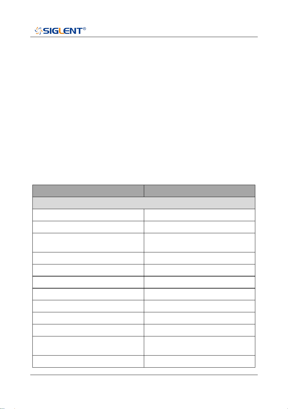
Table 1 Operation Messages
User system message
Message on screen
System message description (1~199)
SWT_OOR (1)
Sweep time out of range
RBW_OOR (2)
RBW out of range
SWT_CCOFM (3)
Can't change the sweep time in FFT
mode
MRKT_UNDEF (4)
Undefined marker type
MRKFT_UNDEF (5)
Undefined marker function type
MRKDT_UNDEF (6)
Undefined marker delta pair type
MRKRT_UNDEF (7)
Undefined marker read out type
TRCT_UNDEF (8)
Undefined trace type
DETT_UNDEF (9)
Undefined detect type
SCA_CSWL (10)
Can't set the Scale/Div with linear
MRKT_IOFF (11)
The marker type is OFF, please open
the current marker
MRK_NDELT (12)
The marker type is not Delta

SHA800A QuickGuide 29
MRKRT_MBST (13)
The marker read out type must be
set time
MATHT_UNDEF (14)
Undefined math type
XML_ANIE (15)
XML attribute node import error
XSCA_MBSLIZS (16)
X Scale must be set liner in zero
span
TG_AXIS_XSCA (17)
The Scale type must be logarithm
when normalize
SCALE_TG_AXIS (18)
Scale type cannot be changed to
linear while nomalize on
PEAK_UNFOUND (19)
No peak found. Please change the
search setting
IMD_FREQ_OOR (20)
Frequency of intermodulation
products out of range
AUTO_FAIL (21)
Auto tune process failed
EXT_REF_PLUG_IN (22)
EXT ref plug in
EXT_REF_PLUG_OUT (23)
EXT ref plug out
REF_PLL_UNLOCK (24)
Ref pll unlock
SIG_NOT_STB (25)
Signal is not stable enough to track
QP_RBW_OOR (26)
RBW out of range when do quasi
peak scan
LAN_PLUG_IN (150)
Ethernet cable plug in
LAN_PLUG_OUT (151)
Ethernet cable plug out
IP_CONFLICT (152)
IP address conflict
IP_INVALID (153)
IP address invalid
NETM_INVALID (154)
Netmask address invalid
GWAY_INVALID (155)
Gateway address invalid
S21_NORMALIZE_DONE (183)
Normalization of S21 done
VNA_AUTO_CAL_DONE (184)
Auto calibration of VNA done
30 SHA800A QuickGuide
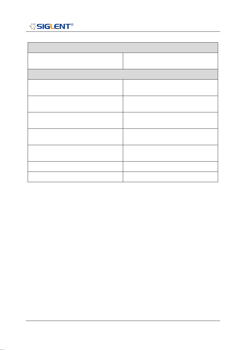
Execution error (400~599)
LCF_DTFERR (400)
Load configurations failed, due to file
error
Device error (600~799)
FUF_DTVERR (600)
Firmware upgrade failed, due to the
version error
FUF_DTRERR (601)
Firmware upgrade failed, due to the
ram error
FUF_DTFERR (602)
Firmware upgrade failed, due to the
file error
FUF_DTFVERR (603)
Firmware upgrade failed, due to
verify the file error
FUF_DTUZFERR (604)
Firmware upgrade failed, due to
unzip the file error
LIC_INVALID (605)
License is invalid!
ADC_ERROR (606)
Warning, ADC Overload!


0 SHA800A
Q u i c k G u i d e
About SIGLENT
SIGLENT is an international high-tech company, concentrating on R&D, sales,
production and services of electronic test & measurement instruments.
SIGLENT first began developing digital oscilloscopes independently in 2002.
After more than a decade of continuous development, SIGLENT has extended
its product line to include digital oscilloscopes, isolated handheld
oscilloscopes, function/arbitrary waveform generators, RF/MW signal
generators, spectrum analyzers, vector network analyzers, digital multimeters,
DC power supplies, electronic loads and other general purpose test
instrumentation. Since its first oscilloscope was launched in 2005, SIGLENT
has become the fastest growing manufacturer of digital oscilloscopes. We
firmly believe that today SIGLENT is the best value in electronic test &
measurement.
Headquarters:
SIGLENT Technologies Co., Ltd
Add: Bldg No.4 & No.5, Antongda Industrial
Zone, 3rd Liuxian Road, Bao'an District,
Shenzhen, 518101, China
Tel: + 86 755 3688 7876
Fax: + 86 755 3359 1582
Email: [email protected]m
Website: int.siglent.com
North America:
SIGLENT Technologies America, Inc
6557 Cochran Rd Solon, Ohio 44139
Tel: 440-398-5800
Toll Free: 877-515-5551
Fax: 440-399-1211
Email: [email protected]m
Website: www.siglentna.com
Europe:
SIGLENT Technologies Germany GmbH
Add: Staetzlinger Str. 70
86165 Augsburg, Germany
Tel: +49(0)-821-666 0 111 0
Fax: +49(0)-821-666 0 111 22
Email: [email protected]
Website: www.siglenteu.com
Follow us on
Facebook: SiglentTech