

Copyright
©2024 Hanwha Vision Co., Ltd. All rights reserved.
Trademark
Each of trademarks herein is registered. The name of this product and other trademarks mentioned in this manual are the registered
trademark of their respective company.
Restriction
Copyright of this document is reserved. Under no circumstances, this document shall be reproduced, distributed or changed, partially
or wholly, without formal authorization.
Disclaimer
Hanwha Vision makes the best to verify the integrity and correctness of the contents in this document, but no formal guarantee
shall be provided. Use of this document and the subsequent results shall be entirely on the user’s own responsibility.
Hanwha Vision
reserves the right to change the contents of this document without prior notice.
❖Design and specifications are subject to change without prior notice.
You can download the latest version from the Hanwha Vision web site. (www.HanwhaVision.com)
❖The initial administrator ID is “admin” and the password should be set when logging in for the first time.
Please change your password every three months to safely protect personal information and to prevent the damage of the
information theft.
Please, take note that it’s a user’s responsibility for the security and any other problems caused by mismanaging a password.
Network Video Recorder
User Manual
Hanwha Vision Co., Ltd. is a surveillance camera manufacturer that provides video information equipment with various functions.
Users must comply with local laws when using our devices.
Users are solely responsible for any illegal use of our products.
English _3
Standards Approvals
■
Any changes or modifications in construction of this device which are not expressly approved by the party responsible for compliance could void
the user's authority to operate the equipment.
■
This device complies with part 15 of the FCC Rules. Operation is subject to the following two conditions: (1) This device may not cause harmful
interference, and (2) this device must accept any interference received, including interference that may cause undesired operation.
■
This equipment has been tested and found to comply with the limits for a Class A digital device, pursuant to part 15 of the FCC Rules.
These limits are designed to provide reasonable protection against harmful interference when the equipment is operated in a commercial
environment.
This equipment generates, uses, and can radiate radio frequency energy and, if not installed and used in accordance with the instruction
manual, may cause harmful interference to radio communications. Operation of this equipment in a residential area is likely to cause harmful
interference in which case the user will be required to correct the interference at his own expense.
■
Reorient or relocate the receiving antenna.
■
Increase the separation between the equipment and receiver.
■
Connect the equipment into an outlet on a circuit different from that to which the receiver is connected.
■
Consult the dealer or an experienced radio/TV technician for help.
PRODUCT USER MANUAL DESCRIPTION
This document is a user manual for Recorder product. Before using this product, please read this document carefully in
order to use it properly.
●
This user manual explains how to use the product based on the defaults and default screens of this product.
●
The content of this manual is subject to change depending on the product software updates and the company
policies. It is subject to partial changes without prior notification to users.
TARGET AUDIENCE
This user manual contains contents for Recorder users.
HOW TO USE THE PRODUCT
Users of this product can perform the following:
●
Monitor cameras registered to Recorder in real time
●
Search for or play videos saved in Recorder
●
Monitor text data being transmitted to the POS device connected to Recorder in real time
●
Search for text data from the POS device connected to Recorder
●
Monitor real time events that occur in Recorder, sensors, and cameras or search through logs
Before using this product, check if the latest version of this software is installed. Go to Hanwha Vision's website
(www.HanwhaVision.com) to check the software version and download necessary files.
IMPORTANT SAFETY INSTRUCTIONS
Read these operating instructions carefully before using the unit.
Follow all the safety instructions listed below.
Keep these operating instructions handy for future reference.
1) Read these instructions.
2) Keep these instructions.
3) Heed all warnings.
4) Follow all instructions.
5) Do not use this apparatus near water.
6) Clean the contaminated area on the product surface with a soft, dry cloth or a damp cloth.
(Do not use a detergent or cosmetic products that contain alcohol, solvents or surfactants or oil constituents
as they may deform or cause damage to the product.)
7) Do not block any ventilation openings, Install in accordance with the manufacturer's instructions.
8) Do not install near any heat sources such as radiators, heat registers, stoves, or other apparatus (including
amplifiers) that produce heat.
9) Do not defeat the safety purpose of the polarized or grounding- type plug. A polarized plug has two blades
with one wider than the other. A grounding type plug has two blades and a third grounding prong. The
wide blade or the third prong are provided for your safety. if the provided plug does not fit into your outlet,
consult an electrician for replacement of the obsolete outlet.
10) Protect the power cord from being walked on or pinched particularly at plugs, convenience receptacles, and
the point where they exit from the apparatus.
11) Only use attachments/accessories specified by the manufacturer.
12) Use only with the cart, stand, tripod, bracket, or table specified by the manufacturer, or sold with the
apparatus. When a cart is used, use caution when moving the cart/apparatus combination to avoid injury
from tip-over.
13) Unplug this apparatus during lightning storms or when unused for long periods of time.
14) Refer all servicing to qualified service personnel. Servicing is required when the apparatus has been
damaged in any way, such as power-supply cord or plug is damaged, liquid has been spilled or objects have
fallen into the apparatus, the apparatus has been exposed to rain or moisture, does not operate normally, or
has been dropped.
15) Prohibition of battery abuse
●
Do not install and use the wrong type of battery.
●
Do not leave the battery in a mechanically crush or cut it because it can explode.
●
Do not leave the battery in a high temperature environment.
●
Do not leave the battery in a low-pressure environment.
overview
• OVERVIEW

4_ overview
overview
CAUTION
●
RISK OF EXPLOSION IF BATTERY IS REPLACED BY AN INCORRECT TYPE. DISPOSE OF USED BATTERIES
ACCORDING TO THE INSTRUCTIONS.
●
Do not ingest battery, Chemical Burn Hazard.
●
This product contains a coin / button cell battery. If the coin / button cell battery is swallowed, it can cause
severe internal burns in just 2 hours and can lead to death.
●
Keep new and used batteries away from children. If the battery compartment does not close securely, stop
using the product and keep it away from children.
If you think batteries might have been swallowed or placed inside any part or the body, seek immediate
medical attention.
ATTENTION
●
IL Y A RISQUE D'EXPLOSION SI LA BATTERIE EST REMPLACÉE PAR UNE BATTERIE DE TYPE INCORRECT.
METTRE AU REBUT LES BATTERIES USAGÉES CONFORMÉMENT AUX INSTRUCTIONS.
●
Ne pas ingérer la pile, risque de brûlure chimique.
●
Ce produit contient une pile de type bouton/pièce de monnaie. Si la pile de type bouton/pièce de monnaie est
avalée, elle peut causer de graves brûlures internes en seulement 2 heures et peut entraîner la mort.
●
Gardez les piles neuves et usagées hors de portée des enfants. Si le compartiment de la pile ne se ferme pas
correctement, cessez d’utiliser le produit et gardez-le d’atteinte des enfants.
Si vous suspectez que des piles ont été avalées ou insérées dans une partie du corps, consultez un médecin
sans tarder.

English _5
FUNCTIONS SUPPORTED BY MODEL
Model name
Function
XRN-426S
Fan X
P2P O
Joystick O
Extended monitor X
Failover O
Alarm O
RAID X
Distributed recording X
iSCSI X
AI compatible function AI search O
AI recognition function
Object detection X
LPR search X
Power supply redundancy X
PoE O
Dewarping X
• OVERVIEW

6_ overview
overview
CONTENTS
OVERVIEW
3
3 Important Safety Instructions
3 Product User Manual Description
3 Target Audience
3 How to Use the Product
5 Functions Supported by Model
6 Contents
10 Starting the system
10 installation Wizard
13 Camera Setup
15 Shutting down the System
15 Restarting the System
15 Login
16 Screen Layout of the Live
17 Checking the System Status
18 Check Camera List
19 Live Screen Menu
19 Icons on the Live Screen
20 OSD Information Display
21 Channel Information Display
21 Check the Camera Status
23 Channel Setting
23 Changing Overall Channel Aspect Ratio
24 Full Screen Mode
24 Setting Up the Live Layout
24 Check Layout List
25 Add Layout and Set Name
25 Delete Layout
25 Change of Layout Channel and Name
25 Dynamic Layout
27 Play Layout Sequence
GETTING STARTED
10
LIVE
16
36 Screen Layout of the Search
36 Time Search
37 Event Search
37 Text Search
38 Export Search
38 ARB Search
39 Bookmark Search
39 Smart Search
SEARCH
36
27 Real-Time Event Monitoring
27 Check Event List
28 Event Search
29 Event Instant Viewer
29 Stop Alarm Output
29 Camera Video Control
29 Manual trigger
30 Capture
30 Instant Viewer
30 Temperature Detection Mode
31 PTZ Mode
31 Zoom In
31 Audio
32 Display Text
32 Change Channel Aspect Ratio
33 PTZ Control
33 Getting Started with PTZ Operations
33 PTZ Control Menu
34 Using Digital PTZ (D-PTZ) Function
34 Preset
34 Running Preset
34 Running Swing (auto pan), Group (scan), Tour, or
Trace (pattern)
35 Exporting the Recorded Video

English _7
STARTING WEB VIEWER
81
LIVE VIEWER
85
43 Screen Layout of the Play
44 Play Search Results
44 Time Line Adjustment
44 Open Time Line Channel
44 Play Button Name and Function
45 Search Results Export
PLAY
43
46 Screen Layout of the Setup
46 Setting the Camera
46 Setting the Channel
50 Setting the Camera Functions
51 Setting the Profiles
54 Setting Camera Password
55 Setting the Recording
55 Record Schedule
55 Record Setup
56 Record Options
56 Setting the Event
56 Event Setup
59 Event Rule Setup
61 Alarm Input
61 ONVIF Setup
61 Schedule
62 Setting the Device
62 Storage Device
63 Monitor
64 Text
SETUP
46
66 Setting the Network
66 IP & Port
67 DDNS & P2P
69 IP Filtering
69 HTTPS
70 802.1x
70 FTP
71 E-mail
72 SNMP
72 DHCP Server
73 Failover
74 Setting the System
74 Date/Time/Language
75 User
78 System Management
79 Log
81 What is Web Viewer?
81 Product Features
81 System Requirements
81 Connecting Web Viewer
82 Set the Recorder Password
82 Installation Wizard
84 Camera Setup
85 Screen Layout of the Live Viewer
86 Checking the System Status
86 Checking User ID
86 Checking Camera List
87 Checking the All Camera Status
87 Live Status
87 Record Status
87 Network Status
87 PoE Status
40 Screen Layout of the AI Search
40 Person Search
41 Face Search
41 Vehicle Search
42 LP Search
AI SEARCH
40
• OVERVIEW

8_ overview
overview
88 Changing the Pattern of Split Screen
88 Changing Overall Channel Aspect Ratio
89 Full Screen Mode
89 Setting up the Live Layout
89 Check Layout List
89 Add Layout and Set Name
90 Change of Layout Channel and Name
90 Delete Layout
90 Real-Time Event Monitoring
90 Check Event List
91 Event Search
92 Event Instant Viewer
92 Stop Alarm Output
92 Live Screen Menu
93 Camera Video Control
93 Manual Trigger
93 Capture
93 PC Recording
93 Instant Viewer
93 Microphone Output
94 PTZ Mode
94 Zoom In
94 Audio
94 Image Rotation
95 Channel Aspect Ratio
95 PTZ Control
95 PTZ Control Menu
96 Using Digital PTZ (D-PTZ) function
96 Preset
96 Running Preset
96 Running Swing (auto pan), Group (scan), Tour, or
Trace (pattern)
97 Exporting Video
AI SEARCH VIEWER
101
SEARCH VIEWER
98
P LAY
104
98 Screen Layout of the Search Viewer
98 Time Search
99 Event Search
99 Text Search
100 Bookmark Search
100 Search Results Export
101 Screen Layout of the AI Search Viewer
101 Person Search
102 Face Search
102 Vehicle Search
103 LP Search
103 Search Results Export
104 Play Search Results
104 To Adjust the Time Line
104 Export Video by Section Setup
105 Play Button Name and Function

English _9
EXPORT VIEWER
120
APPENDIX
122
120 SEC Backup Viewer
120 Recommended System Requirements
120 Screen Layout of the Backup Viewer
122 Using Virtual Keyboard
122 Troubleshooting
SETUP VIEWER
106
106 Screen Layout of the Setup Viewer
106 Setting the Camera
106 Channel setup
106 Camera setup
107 Profile Setup
108 Camera Password
108 Setting the Recording
108 Record Schedule
108 Record Setup
109 Record Options
109 Setting the Event
109 Event Setup
111 Event Rule Setup
111 Alarm Input
111 ONVIF Setup
111 Schedule
112 Setting the Device
112 Storage Device
112 Monitor
113 Text
113 Setting the Network
113 IP & Port
114 DDNS & P2P
114 IP Filtering
114 HTTPS
114 802.1x
115 FTP
115 E-mail
116 SNMP
116 DHCP Server
117 Setting the System
117 Date/Time/Language
117 User
118 System Management
118 Log
• OVERVIEW
10_ getting started
Starting the SyStem
1. Connect the power cable of the recorder to the wall outlet.
2. You will see the initialization screen.
The initialization process will last about 2 minute. If a new HDD is installed, the initialization process may take longer.
3. The live screen appears with a beep.
The following symptoms might be observed when starting the system.
■
If the HDD number is displayed at the bottom of the screen along with < > while the product is booting up, it indicates that the HDD is in recovery,
and for this reason booting up may take longer.
HDD 1, 2
■
If the progress stalls while in < > state, it indicates that the HDD has problems. Visit your nearest customer service center to check the HDD.
HDD 2
getting started
inStallation Wizard
As shown below, proceed through each step of the <installation wizard>.
Install Wizard can only be accessed at factory reset. If you do not want to proceed, click <exit>.
■
It will automatically change to the optimal monitor resolution and run the install wizard.
■
If the install wizard does not run, remove the monitor connection from the back of the recorder, reboot the recorder and reconnect the monitor.
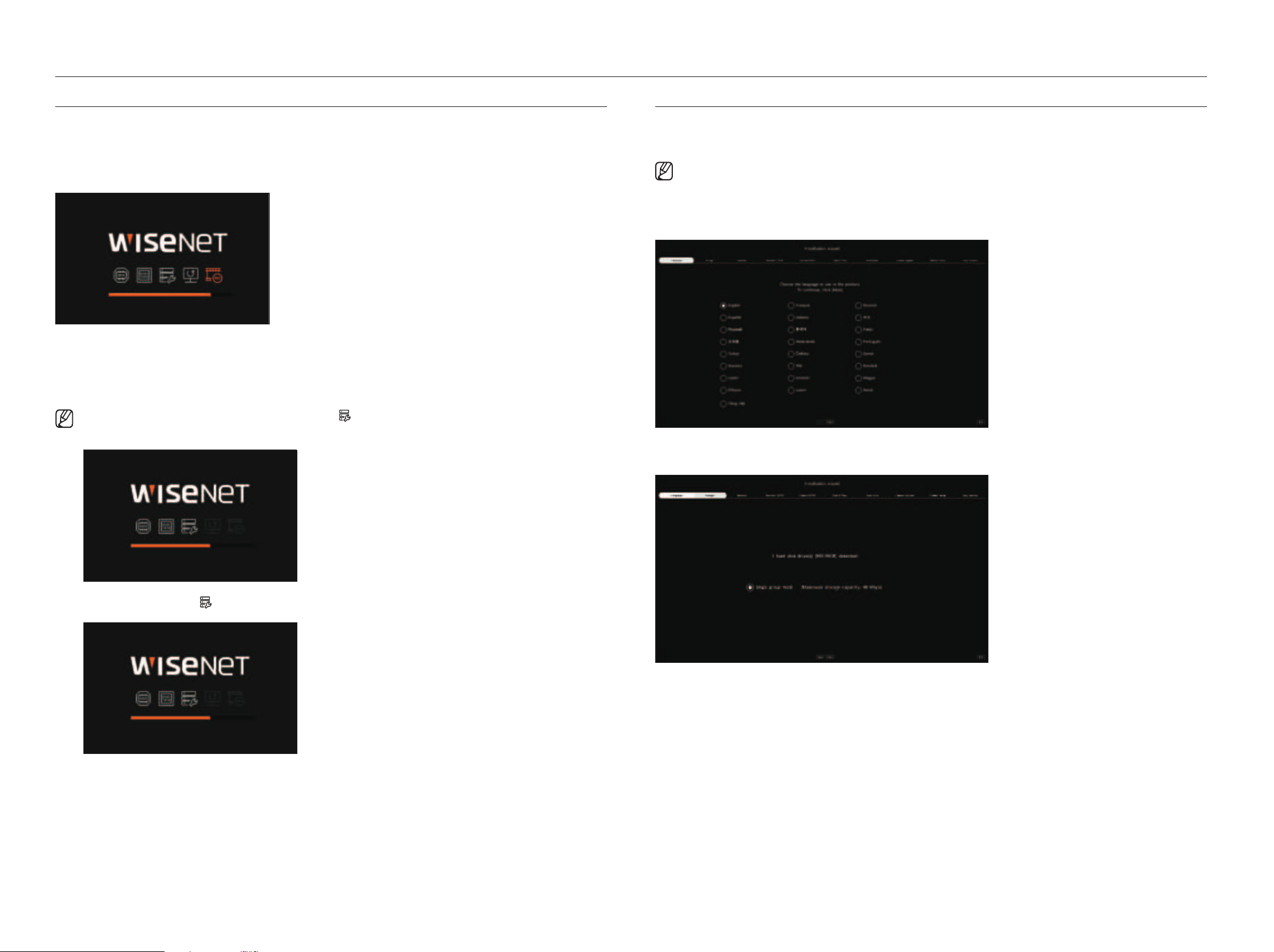
1. In the <language> screen, select the language and press the <next> button.
2. Set the video recording method on the <Storage> screen, and then click <next>.
●
Single group mode : Saves data on one hard disk. If the hard disk is recognized as an unusable hard disk in the
recorder, the data can be saved after formatting the hard disk.
English _11
Setting the camera registration method
This function is only available for products that support PoE. For products that support PoE, refer to the
"Functions Supported by model" page.
●
Enable PnP mode: Cameras connected to the PoE port of the product will automatically be registered for each
channel in order of port number.
– When the camera resets to factory default, it defaults to the ID and password set during the <Camera id/
PW> step. If the camera ID and password are not set, the recorder ID and password will be set automatically.
– If the camera's ID and password have already been set, the information that matches the ID and password
set during the <Camera id/PW> step will be registered (up to 3 sets).
If your camera uses a manual IP, its bandwidth should match with that of Network 1 IP for registration.
– If manual mode is used, it automatically detects and registers cameras connected to the recorder’s PoE port
and cameras connected to a separate switch.
online Upgrade
You can receive a new firmware notification when the recorder is connected to a network.
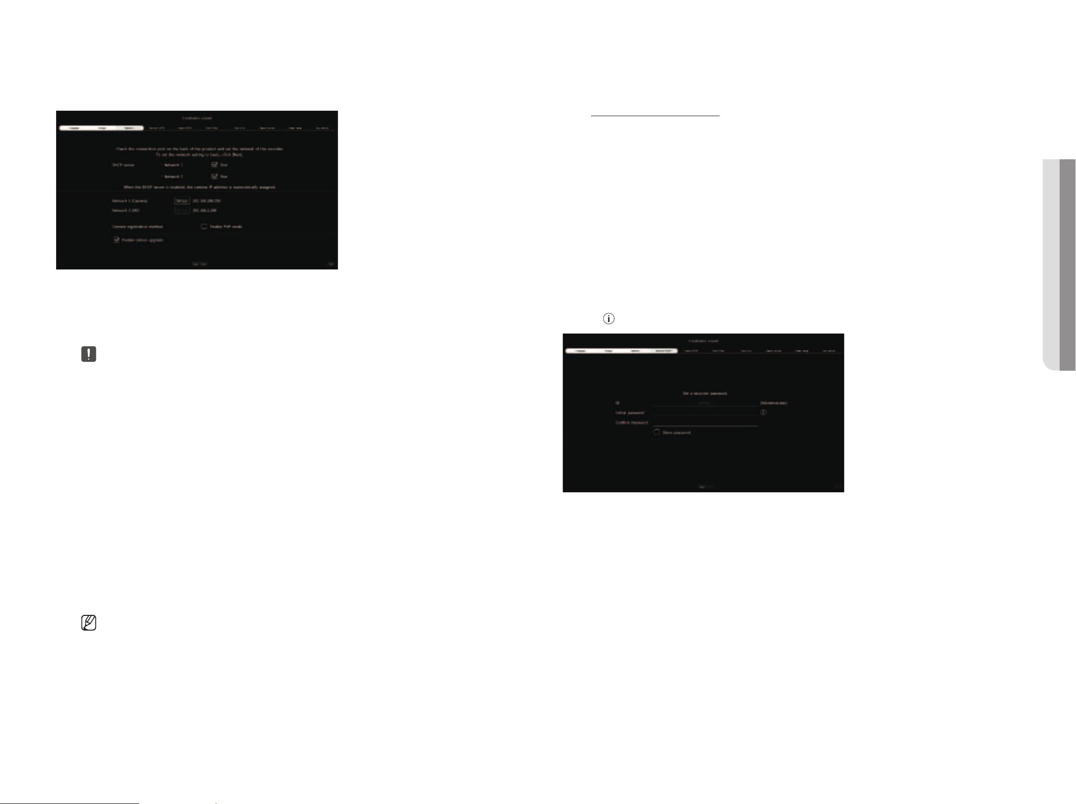
4. Set the administrator password on the <recorder id/PW> screen and click the <next>.
Click <
> to view the basic guide for setting a password. Refer to the password setup rules.
3. Set the network connection type and the connection environment on the <network> screen, and then click the
<next>.
Setting up the dhCP server
If you set up the DHCP server to <run>, the IP address is automatically assigned to your camera.
For more details, refer to the "Setup > Setting the network > dhCP Server" page in the Table of Contents.
■
Depending on the camera's state, no IP may be automatically assigned to the camera. After exiting the installation wizard, go to the menu to
assign an IP to DHCP, or set the IP manually.
Setting up the network
Each product supports a different number of network ports. If it supports two or more network ports, you can set
the network for each function as follows. Click <Setup> of the network connected to the recorder.
●
Network 1 (Camera) : Can be used as a port for connecting a camera. If you connect a camera, then the camera
video will be transmitted.
●
Network 2 (Viewer) : Can be used as a port transmitting video to the web viewer. If you access the network
information on your browser, then you can remotely monitor video in your web viewer.
●
Network 3 (iSCSI) : Can be used as a port for an iSCSI connection.
■
Only provided for products that support Network 3.
●
Network (All) : Can be used as a common port for connecting camera, web viewer, and iSCSI.
– IP type : Allows you to select the type of network access.
– IP Address, Subnet Mask, Gateway, DNS
■
Manual : IP address, subnet mask, gateway, and DNS can be directly entered.
■
DHCP : IP address, subnet mask, gateway, and DNS can be automatically set.
■
If the LAN cable is not connected to the port, <Setup> button will not be activated for use. Check the LAN cable connection.
(In case of a PoE product, Network 1 is activated.)
■
The built-in DHCP Server in Recorder will turn on automatically at stage 1. At this stage, using the existing DHCP server in the same network
may cause a problem, as two DHCP servers would be simultaneously operating.
■
A product with multiple network ports cannot use a single bandwidth for all of them.
Example)
– Port 1 : 192.168.100.199 / Port 2 : 192.168.100.198 (X)
– Port 1 : 192.168.100.199 / Port 2 : 192.168.101.198 (O)
• getting Started
12_ getting started
getting started
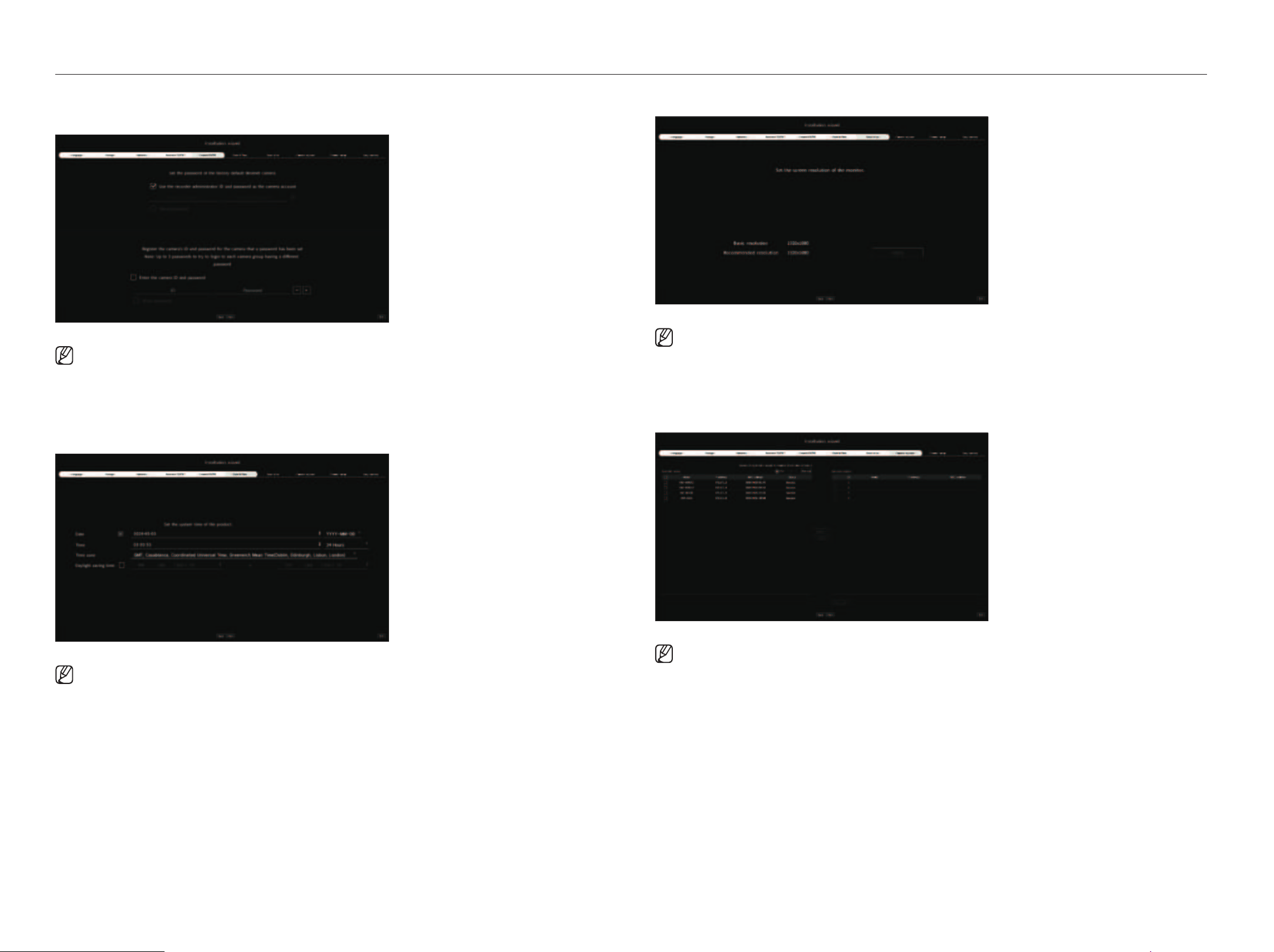
5. Set the camera password in factory reset on the <Camera id/PW> screen.
If ID/PW is already set in the camera, register the ID/PW and click <next>.
■
When the password is in factory reset, it can be changed and managed in a batch.
■
Up to 3 sets of camera ID with password and password can be registered.
■
You may change the passwords of registered cameras all at once in the "Setup > Camera > Camera password" menu.
■
You cannot change the password for cameras registered with ONVIF and RTSP.
6. Set the date, time, and daylight saving time on the <date & time> screen, and then click the <next>.
■
The time zone setup might differ depending on the region that the product is released.
7. To set the recommended resolution on the <resolution> screen, click <apply> followed by the <next> button.
■
This function is not supported in some models.
8. On the <Camera register> screen, select a camera to register from the searched camera list and click <register>.
Select a camera to register from the list and click <Change iP>.
After completing camera register click <next>.
■
After entering the ID and password set in the camera, the connection test must be completed to successfully register.
English _13
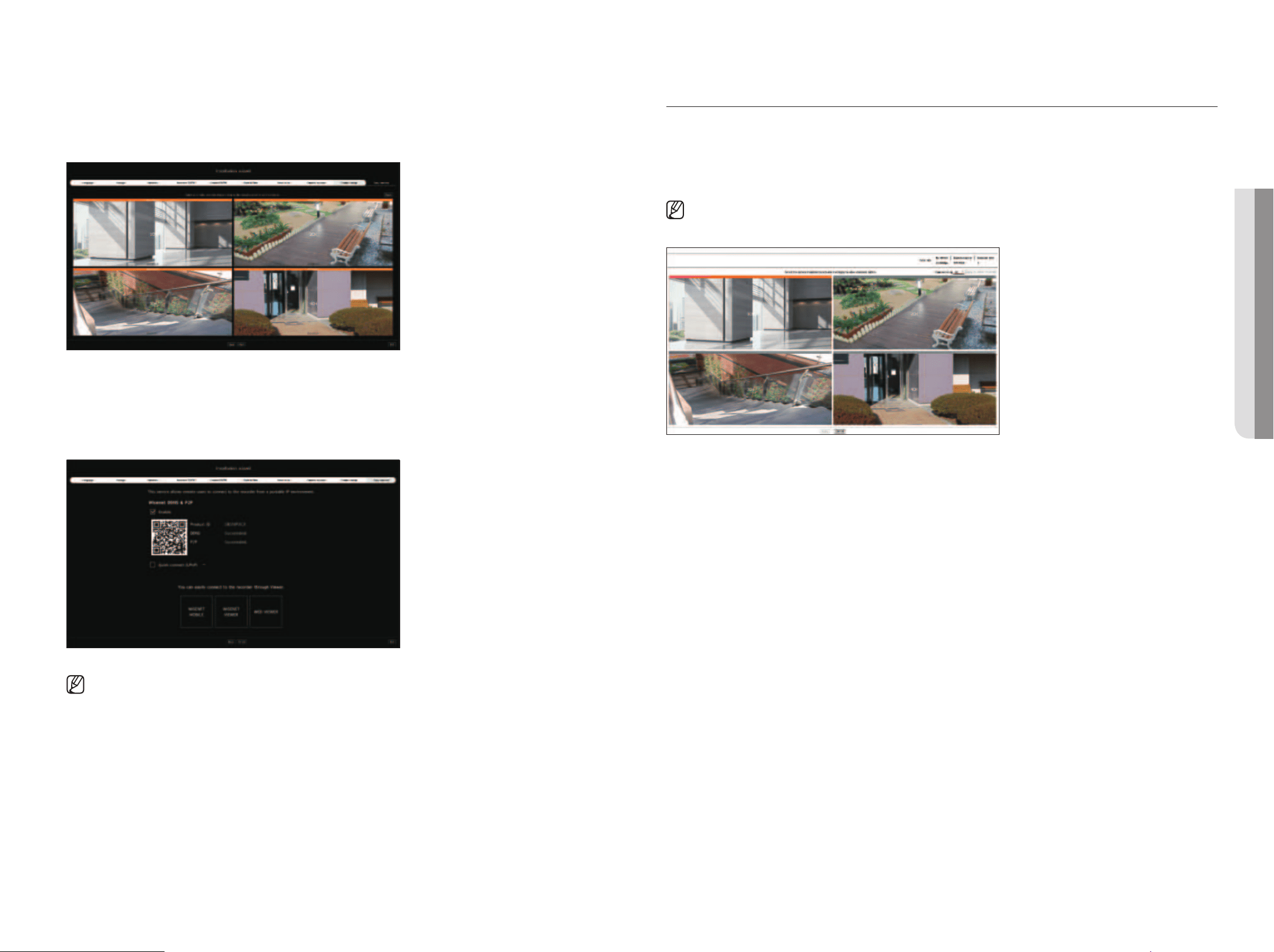
9. On the <Channel setup> screen, you can view the camera videos registered to each channel in thumbnails along
with thumbnail information. To change the camera video position, select a video and drag and drop it to the desired
location.
After completing channel setup, click <next>.
10. On the <easy connect> screen, a remote user can network a recorder in a dynamic IP system.
Click <enable> to test the connection to see if the current recorder can be connected remotely. When the
connection is successful, a QR code is created.
To connect a recorder via a viewer, select the viewer you want to use. You can check the connection method of the
selected viewer in the popup window.
■
It connects to Wisenet DDNS first. If it does not connect to DDNS, it automatically connects to P2P.
11. Click <Finish> to complete the Installation wizard.
Camera SetUP
When the installation wizard closes, the camera setup screen will automatically appear.
Based on the registered camera's record profile information, you can check the total bandwidth, expected space, and
expected days.
You can change camera setup and the record schedule, and apply the same settings to other channels.
■
The camera setup screen is also displayed when registering a camera for the first time in the "Setup > Camera > Channel setup" menu.
●
Bandwidth/Expected space/Expected days : Displays the total bandwidth, expected space, and the expected days of
the registered camera.
(This may differ from the actual recording content.)
●
Dual recording : You can select whether to use dual recording or not.
●
Apply to other channels : You can apply the settings of the selected channel to other channels in the same way. Select
the desired channel in the “apply to other channels” confirmation window and click <ok>.
■
Applicable only for channels registered with the same camera model.
• getting Started
14_ getting started
getting started
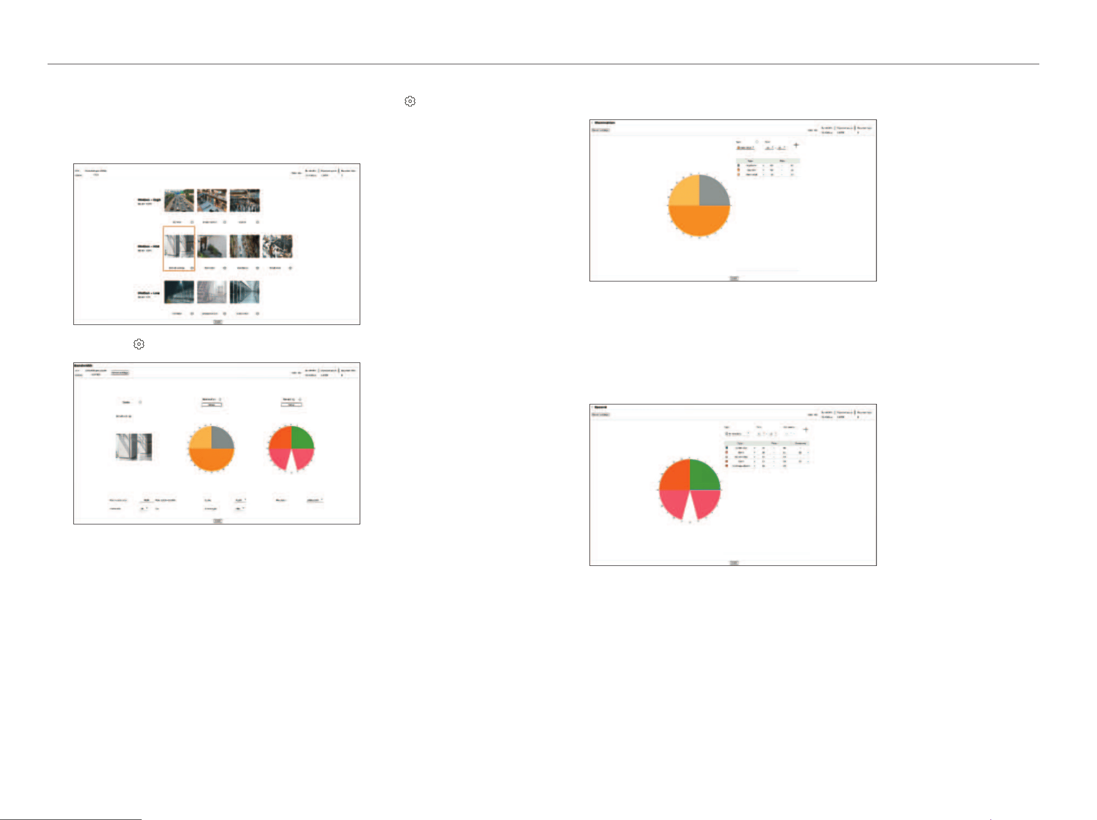
Configuring the Video environment
Select the thumbnail of the channel whose settings you want to change and click < >. The setting window
that was classified according to the scene will appear.
You can select items that are relevant to your channel. A video with more motion may have a higher bitrate,
resulting in a larger expected space and fewer expected days.
You can click <
> to change to the setting you want.
●
Expected space/1Day : Displays the expected space based on one day.
●
Revert settings : Reverts to the settings that were set before the user modifies them.
Configuring the illumination
You can click <Setting> to change to the setting you want.
Set up the desired type and time.
●
The bitrate is higher in the following order : nighttime > illuminated > daytime.
●
Revert settings : Reverts to the settings that were set before the user modifies them.
Setting the recording
You can click <Setting> to change to the setting you want.
Set up the desired type and time.
●
Not recording : Do not record for the set time.
●
Continuous, Continuous/Event : Recording is executed for the set time.
●
Event : When an event occurs at the set time, a recording will be executed.
You can set the occupancy (10 to 90) indicating the frequency of movement.
●
Revert settings : Reverts to the settings that were set before the user modifies them.
English _15
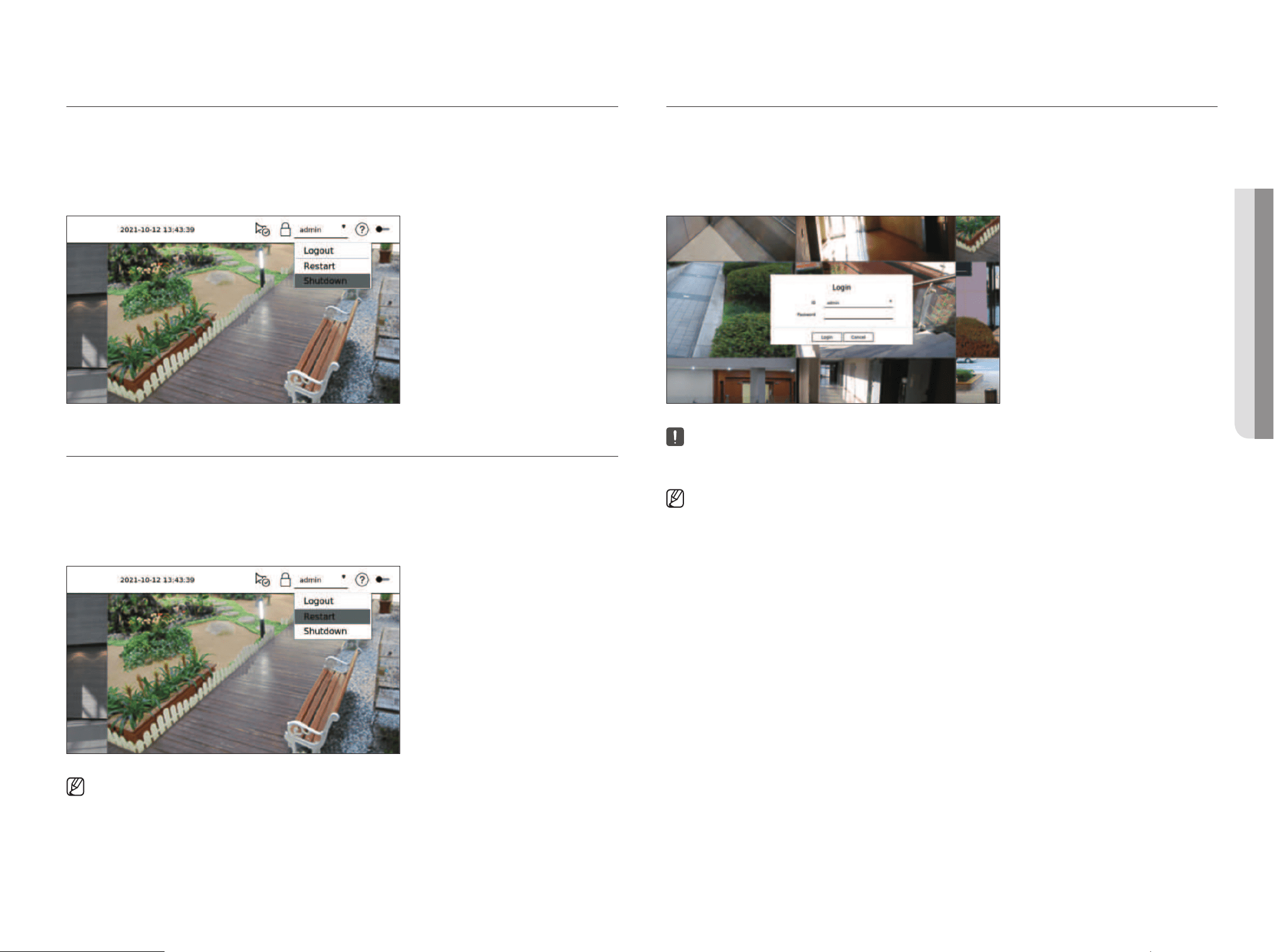
ShUtting doWn the SyStem
1. Select <Shutdown> at the top right of the screen.
2. The <Shutdown> window will appear.
3. Click on <oK>.
The system will shut down.
reStarting the SyStem
1. Select <restart> at the top right of the screen.
2. The <restart> window will appear.
3. Click on <oK>.
The system will restart.
■
Only the user with the "Restart/Shutdown" permission can shut down or restart the system.
■
To manage Permission Setup, refer to the "Setup > Setting the system > User" page in the Table of Contents.
login
To use the Recorder menu, you are required to login as a user that is authorized to access the applicable menu.
1. Select <login> at the top right of the screen.
2. The <login> window will appear.
3. Enter the user ID and password, then click <login>.
■
The initial administrator ID is "admin" and you will need to configure the password in the installation wizard.
■
Please change your password every three months to safely protect personal information and to prevent the damage of the information theft. Please,
take note that it’s a user’s responsibility for the security and any other problems caused by mismanaging a password.
■
For more information about limited-access permission, refer to the "Setup > Setting the System > User" page in the Table of Contents.
• getting Started
16_ live
Shows the video of the camera connected to the recorder. Also, you can adjust the camera and check the network
transfer status.
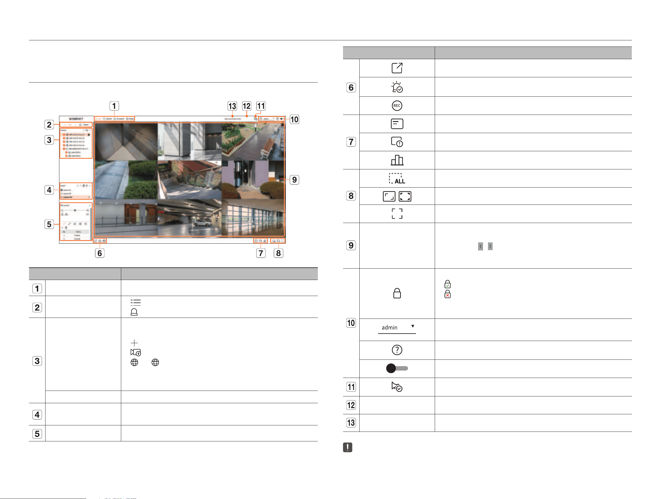
SCreen layoUt oF the liVe
The live screen is built as follows.
Item Description
Menu Click each menu to go to the corresponding menu screen.
List/Event
●
List
: Select to check the camera list.
●
Event
: Select to check the event list
Camera list
The list of cameras registered in the recorder is displayed.
You can also register the camera manually or automatically.
●
: Registers the camera manually.
●
: Searches and registers the camera connected to the recorder automatically.
●
: The < > icon is displayed when you mouse over the camera list. Click the icon to go to the camera
web page.
To go to the camera webpage, you must have the right to set cameras, profiles, and events, and set <Video> to
<On> in the "Setup > Camera > Channel setup" menu.
Event List A list of events that have occurred on the camera is displayed.
Layout list
Displays the default layout and a list of created layouts.
You can also set and play a sequence of layout lists.
PTZ control Controls the connected PTZ camera.
Item Description
Saves the recorded video of the selected channel in the designated path.
Clears the alarm in the event list and stops the alarm/beep sound for the system status when it is emitted.
Activates the manual recording function of the recorder.
Displays information of the OSD screen on the video window.
Shows channel information.
Shows the status of all cameras connected to the recorder.
Removes all screens from the video window.
/
Shows the video in its original aspect ratio or full screen.
It changes to full screen from the current split mode.
Video window
Shows the video of the camera connected to the recorder.
●
You can change to single screen by double-clicking the desired video in Split mode. To move to the previous or
next video, click the
or button that appears when you mouse over the center of the left or right side of the
video.
●
If you double-click the video in single screen, it will change to split screen.
Displays the IP address and mutual authentication status of the viewer receiving the video from the recorder.
●
: Mutual authentication connection using WISENET device certificates
●
: Mutual authentication connection without WISENET device certificate
●
– : Connection without mutual authentication
●
No viewer connected: Displayed when there is no viewer connected to the recorder.
The ID of the connected user is displayed.
The <Logout/Restart/Shutdown> menu will appear if you click.
Displays a QR code to download the user manual.
Changes the color theme of the screen.
Stops the alarm/beep sound for the system status when it is emitted.
System status display Displays the status of the system, hard disk, and network.
2020-09-27 10:31:20 Displays the current time and date.
■
If the camera's frame rate is set to 60 fps, the frame rate could be reduced on the live screen depending on the monitor resolution output.
live
English _17
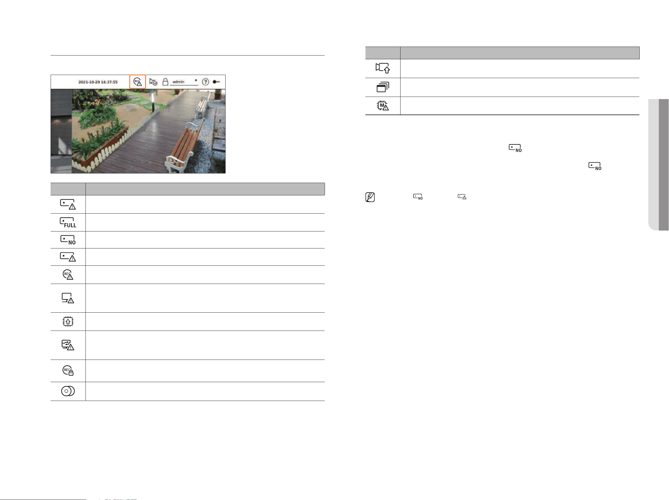
Checking the System Status
The icon at the top of the screen indicates the status of the system.
Item Description
Display when recording data is not properly saved.
Displayed if the HDD is full and the Recorder has an insufficient space to record.
Displayed when there is no HDD or HDD is not detected.
Displayed if the HDD needs a technical examination.
Appears when input data rate per channel exceeds the specified data rate limit.
It is displayed when the network is overloaded.
■
It occurs when the max receiving allowance is exceeded, causing an overload to the CPU. It disappears when you modify the
Delete Camera or Set Camera to reduce the data rate.
Displayed if the server has firmware to update.
It is displayed when the system is overloaded.
■
Limit the number of users remotely monitored by Web Viewer or VMS, or control the number of events displayed in the event list
of the recorder.
Displayed when manually recording a video while the access restriction for stop recording is enabled.
Only a user with the permission to stop recording is allowed to stop recording.
Displayed when exporting a recorded video in live mode.
Item Description
Displayed when there is software to update on the camera.
Displayed when playing the layout sequence.
Displayed when an error occurs in the internal memory.
error information
●
If the built-in HDD is not connected, the "NO HDD" icon (
) will be displayed. You must contact the service
center since the Recording, Play, Export, and Upgrade functions do not work while doing this.
●
If you do not format a purchased HDD in a format supporting Recorder, a "NO HDD" icon (
) will be
displayed. If the "No HDD" icon is displayed, check the hard disk connection status in "Setup > device >
Storage device" and format the hard disk.
■
If the NO HDD ( ) icon or HDD FAIL ( ) icon is displayed, contact our customer service.
• liVe
18_ live
live
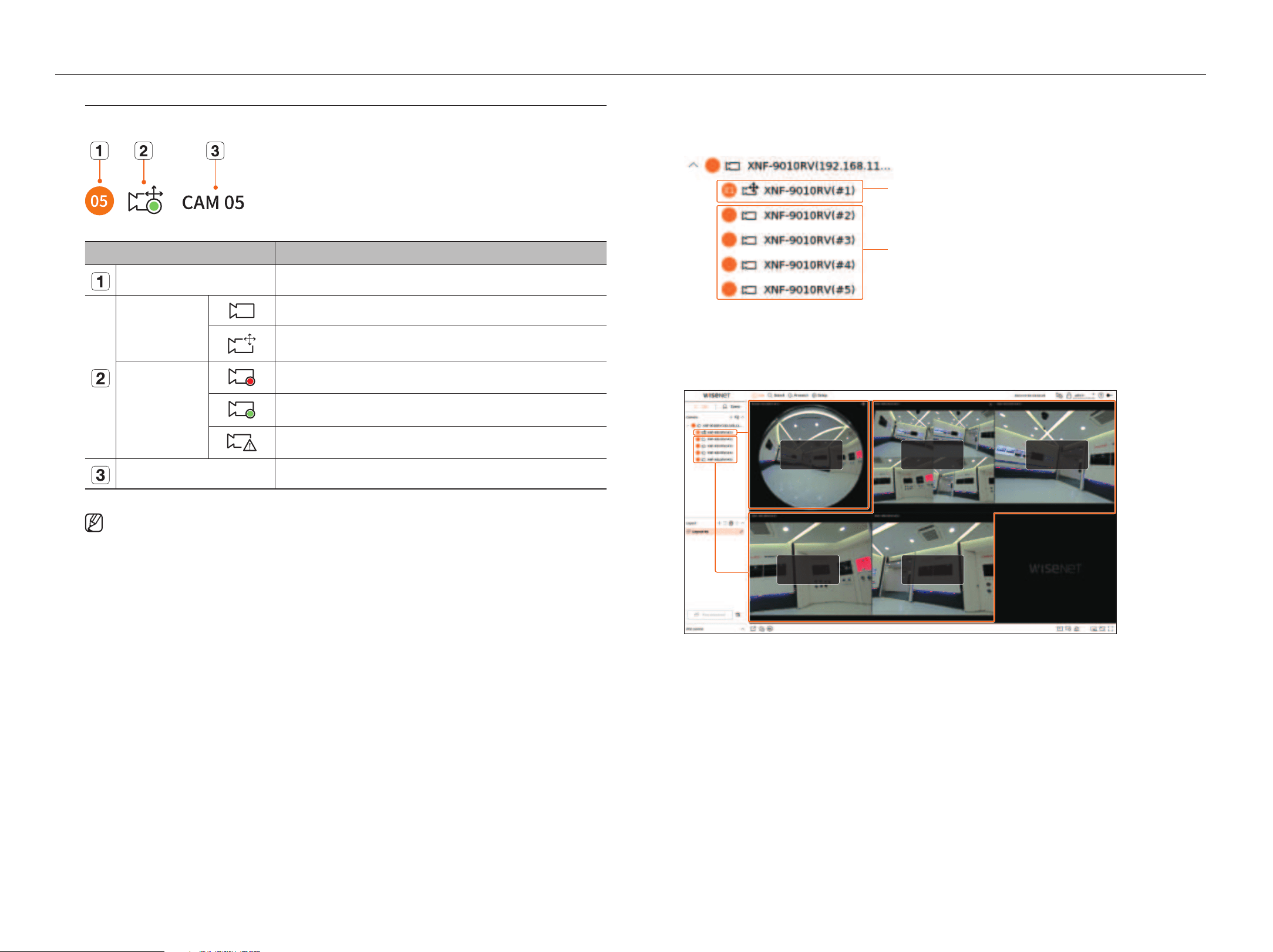
Check Camera list
Displays the camera type, status, and name registered in the recorder.
Itrem Description
Channel information Displays channel information (channel number, video window assignment, and color indication).
Camera type
Displays a normal camera.
Displays a PTZ camera.
Camera status
Recording an event video.
Recording a general video.
Displays the camera error status.
Camera name Displays the name set for the camera.
■
If a camera connection error occurs, it is disabled in the list.
■
The camera status display information changes according to the network connection status and settings.
Check multichannel Cameras list
For multichannel cameras registered with the Wisenet protocol, the channel information will be displayed under
the model name of the multichannel camera.
Registered channel
(recording channel)
Unregistered channel
(virtual channel)
In case of multichannel cameras, only one main channel can be registered for recording.
Subchannels in which recording is not required do not need to be registered on the recorder, as they can be
monitored real time. However, recording, event reception, or camera settings are not available.
Registered channel
(recording channel)
Unregistered channel
(virtual channel)
Unregistered channel
(virtual channel)
Unregistered channel
(virtual channel)
Unregistered channel
(virtual channel)
English _19
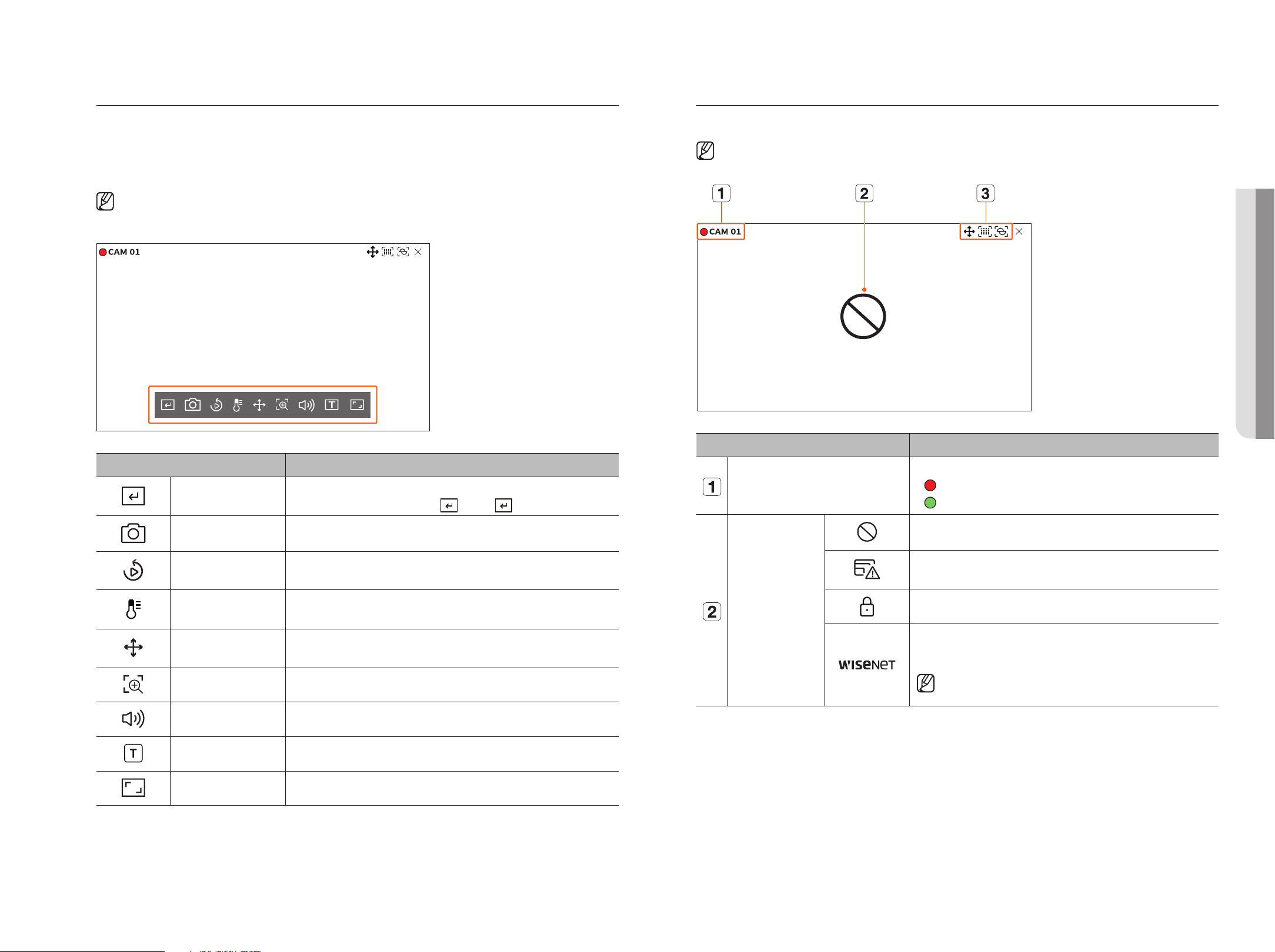
live Screen menu
After selecting the desired channel on the split mode, roll the mouse cursor over the screen to see the live screen
menu.
The live screen menu appears differently depending on the recorder operation status or the type of the
registered camera.
■
Each function may be restricted depending on the type of camera and the user's authority.
■
For more detailed information about each function, refer to the table of contents "Live > Camera Video Control".
Item Description
Manual trigger
If the event action for <Manual trigger> is set for the selected channel, the event rule name is
displayed when you hover the mouse over <
>. Click < > to activate the set event.
Capture You can take a screenshot of the selected channel.
Instant Viewer You can rewind 30 seconds while monitoring the video.
Temperature Detection
For images that support the thermal imaging camera function, you can click the desired point to
check the temperature information.
PTZ control
If the network camera connected to the selected channel supports the PTZ function, it changes to
the PTZ control mode.
Zoom in You can zoom in or zoom out the video.
Audio Turns the audio on or off when the audio is connected.
Display Text Turns the text output on or off.
Channel aspect ratio Shows the video in actual proportions.
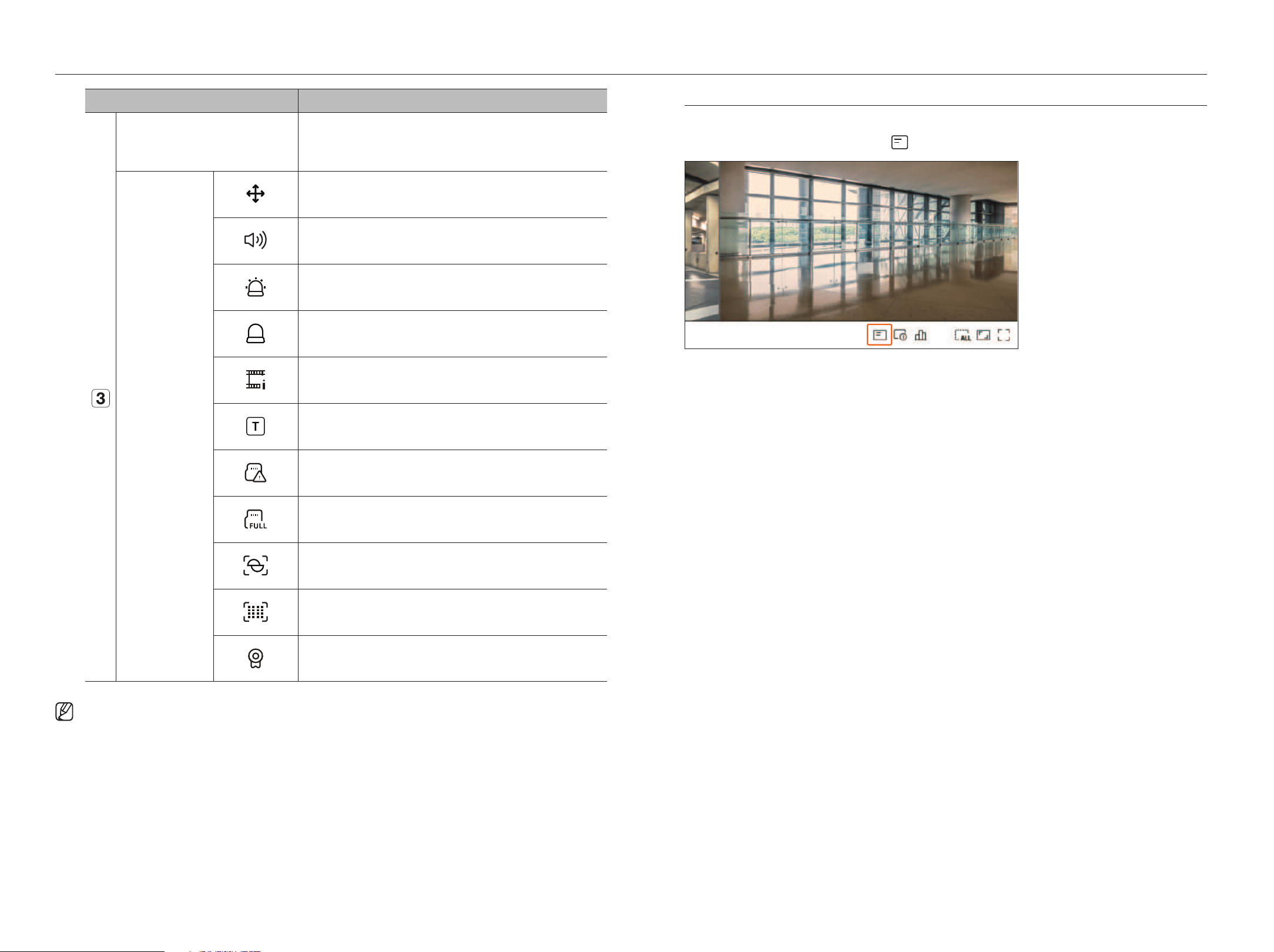
icons on the live Screen
You can check the status or operation with the icons on the live screen.
■
The icons displayed on the screen may differ depending on the type of camera and the user's authority.
Item Description
Recording status and camera name
Displays camera's recording status and name.
●
: Displays the event recording.
●
: Displays the normal recording.
Video input status
Displayed when there is no input while the camera is on.
Displayed when the resolution of the live video exceeds the supported range while the
camera is on.
Displayed if no permission to live view is granted.
Displayed when the camera is not registered.
If you set the channel setup to <Covert2>, nothing will be displayed on the live screen.
■
If you set the channel setup to <Covert1>, the video will not displayed on
the live screen, but only the OSD will be displayed.
• liVe
20_ live
live
Item Description
Event Display
Events from the recorder and camera are displayed in icons.
For details, refer to the "Setup > Setting the Event > Event rule setup" page in the
Table of Contents.
Status Display
It is displayed on the channels that can enable the PTZ mode.
Displays AUDIO ON/OFF.
It will not be displayed when <Off> is selected for the audio in the channel setup.
If the alarm in is set, it is displayed on the connected channel when an external signal is
entered.
If the event detection is set for each channel, it is displayed when a camera event occurs.
It is displayed when it fails to decode all the frames due to limited decoding performance
and in this case only the I-Frame is decoded.
This is displayed when a POS (text) event occurs.
Displayed when there is an error with the SD card.
Displayed when the SD card capacity is full.
Displayed when a defocus event occurs.
Displayed when a fog detection event occurs.
Displayed if the Wisenet camera's certificate is valid.
■
The 'Live4NVR' profile is added automatically with network camera auto registration, and settings can be changed according to user
environment.
■
Depending on camera specification, you may not be able to add a profile or if you have the PLUGINFREE profile, you will not be able to add the Live4NVR
profile.
■
When system overloaded and the performance is down, network camera may play only main frame(I-frame).
■
To set profiles, refer to "Setup > Setting the Camera > Setting the Profiles" page in the Table of Contents.
oSd information display
You can show or hide the recording status, camera status, event display, etc. in the video window.
To show or hide the OSD information, click <
> at the bottom of the screen.
English _21
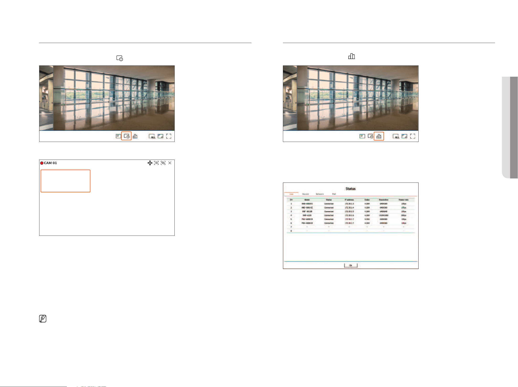
Channel information display
You can check the information of the video being recorded with each camera.
To check the channel information, click <
> at the bottom of the screen.
The information of the current video is displayed on the live video which is being monitored.
800x448 (H.264)
S/I/D 25/24/24
XNV-6081Z(S)
●
800x448 : Displays the resolution of the video.
●
H.264 : Displays the video codec.
●
S/I/D 25/24/24 : Displays the frame rate (FPS) of the video. (S : Settings, I : Video input, D : Video display)
●
XNV-6081Z : Displays the camera model name.
●
CH1 : For multi-channel cameras, the channel number is be displayed. The channel number may not be
displayed depending on the camera.
●
S : Displays the protocol used when registering the camera.
– S and V represent Wisenet protocol while O represents ONVIF.
– When connected by RTSP protocol, only RTSP is displayed without the product name.
■
ARB is only visible when an ARB situation occurs.
Check the Camera Status
You can check the status of all cameras connected to the recorder.
To check the camera status, click <
> at the bottom of the screen.
live Status
Select <live> in the <Status> menu to check the transmitted data from a network camera connected to each
channel.
●
Model : Displays the model name of camera connected to each channel.
●
Status : Shows the connection status of camera set to each channel.
●
IP address : Displays the IP address of a camera set to each channel.
●
Codec : Displays the live profile codec information for a camera set to each channel.
●
Resolution : Displays the live profile resolution of a camera set to each channel.
●
Frame rate : Displays the live profile transmission rate for a camera set to each channel.
• liVe
22_ live
live
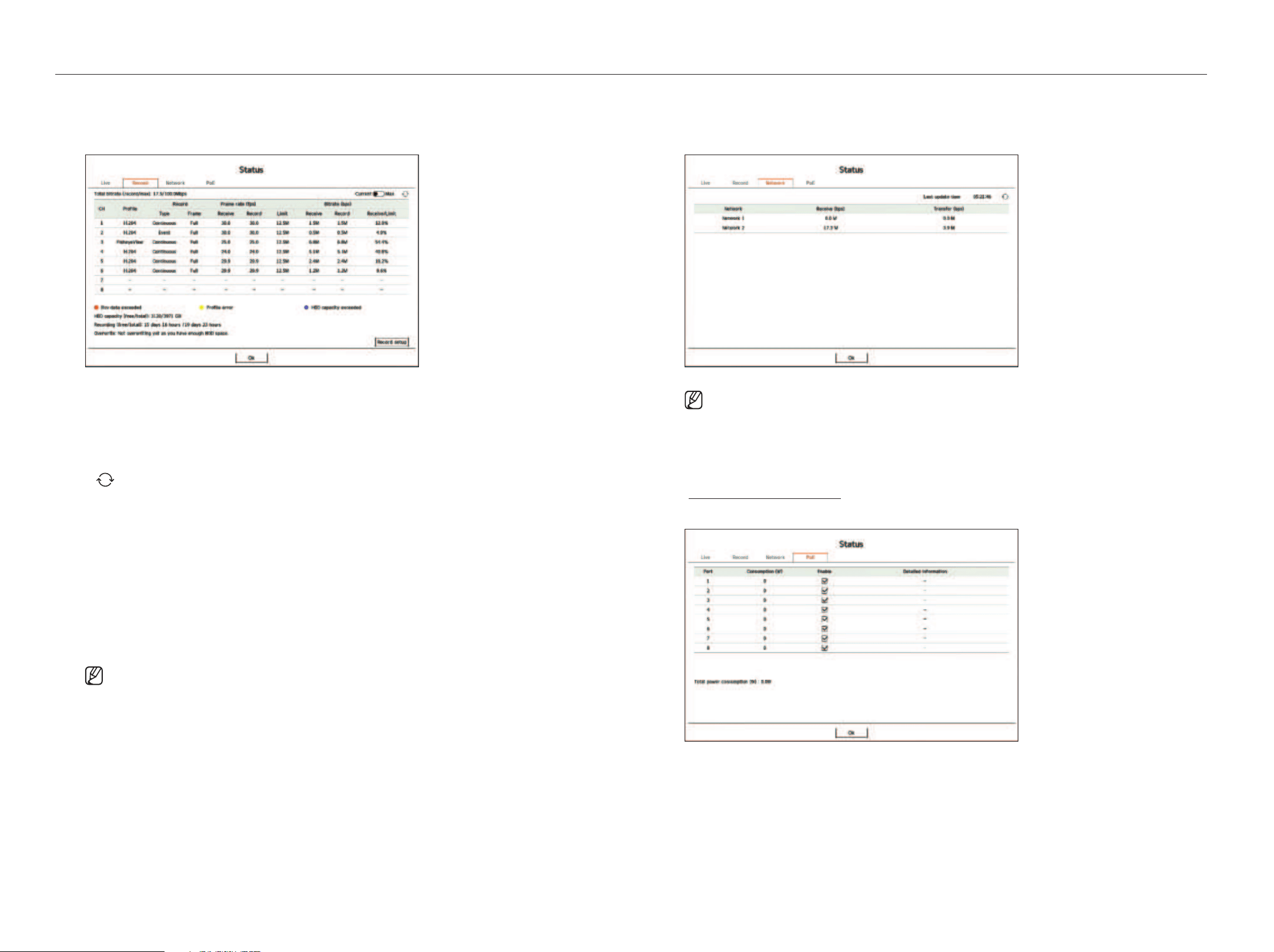
record Status
If you select <record> in the <Status> menu, you can check the profile, record type, frame rate (Input/Record),
and bit rate (Limit/Input/Record) for each channel.
●
Total bitrate (record/max) : Record shows the amount of data currently being recorded, and Max shows the
amount of recorded data allowed for the recorder.
●
Current : Shows the recording status information of currently transferred data.
●
Max : Shows recording information of the most biggest recording data out of configured standard and event
recordings.
●
: Reloads the recording information.
●
Profile : Shows the video profile configured to each channel.
●
Record : View the record type according to normal or event recording.
●
Frame rate (fps) : Shows the receive/record frames per second for each channel.
●
Bitrate (bps)
– Limit / Receive / Record : Shows the amount of limit/receive/record data for each channel.
– Receive/Limit : Shows the data ratio of actual data transferred from the camera and allowed maximum
defined by user.
●
Record setup : You can set detailed recording settings.
For more details, refer to the "Setup > Setting the recording > record Setup" page in the Table of Contents.
■
If an error occurs during recording, the channel's profile column turns yellow.
This profile error indicates that when a recording profile cannot be used to receive video from camera, an alternative profile is used to record the
video. When the recording profile resumes, the camera video can record by using the set recording profile.
■
If Recorder exceeds the recording limit, only the key frame will be recorded. In that case, a restricted recording popup and an icon will appear.
The restricted recording popup appears only once. If you change the camera setup and record setup, the restricted recording popup may appear
once more to confirm the status.
If you don't want to see it again, then check Do not show this again in the popup.
For the maximum allowed number of recoding, refer to the "Setup > Setting the Recording > Record Setup" page in the Table of Contents.
■
For dual recording, the bitrate is shown as the sum of recording and remote profiles.
However, the <Enable dual recording> box in the "Record > Record options" menu must be checked.
The recording profile and remote profile can be set in the "Camera > Profile setup" menu.
network Status
Select <network> in the <Status> menu to check the status of network bandwidth currently being received/
transmitted.
■
Each product supports a different number of network ports.
Poe Status
This function is only available for products that support PoE. For products that support PoE, refer to the
"Functions Supported by model" page.
Select <Poe> in the <Status> menu to check the current PoE status of each port.
●
Consumption (W) : Displays the power consumption in PoE.
– 0 : No device is connected to the port or device is using its own power supply.
– – : Port failure (Failure information is displayed in detailed information.)
English _23
●
Enable: Turns on/off the power supply to the camera.
– Checked (
): Power supply available
– Not checked (
): Power supply limited
●
Detailed information: If there is a problem with power supply, it is described here. Power supply problem
includes overload power (Class 1 to 4) and voltage fault.
●
Total power consumption (W): Displays the sum of power consumption of all ports.
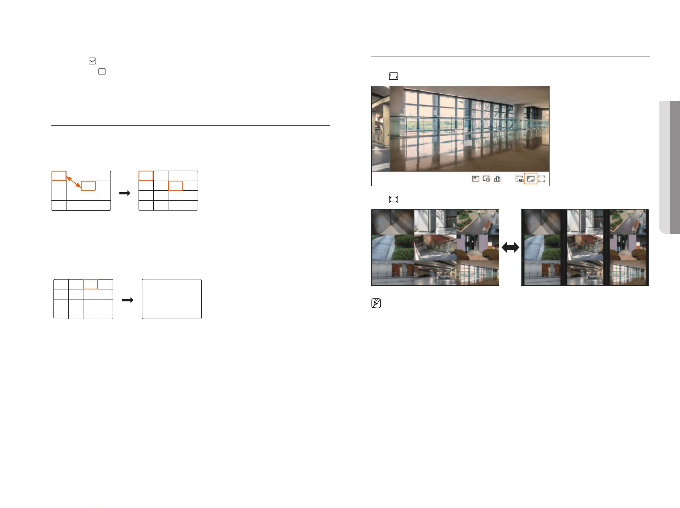
Channel Setting
You can display the channel in a desired area of a split screen.
To switch the position of a channel, hold a channel and drag and drop it to the desired location.
example) if switching Ch 1 to Ch 7
CH15
CH11
CH16
CH12
CH7
CH3
CH8
CH4
CH13
CH9
CH14
CH10
CH5
CH1
CH6
CH2
CH15
CH11
CH16
CH12
CH1
CH3
CH8
CH4
CH13
CH9
CH14
CH10
CH5
CH7
CH6
CH2
Switching to Single mode
When in split mode, select and double-click a desired channel to switch to its Single mode.
example) if double-clicking Ch 3
CH15
CH11
CH16
CH12
CH7
CH3
CH8
CH4
CH13
CH9
CH14
CH10
CH5
CH1
CH6
CH2
CH3
Changing overall Channel aspect ratio
Video screen ratio for all channels can be changed in live split screen mode.
Click <
> at the bottom of the screen. It changes to the actual proportion of the video.
Click < > to return to the previous aspect ratio.
■
You can change the aspect ratio of each channel. For more information, refer to the "Live > Camera Video Control > Change Channel Aspect
Ratio" page in the Table of Contents.
• liVe
24_ live
live
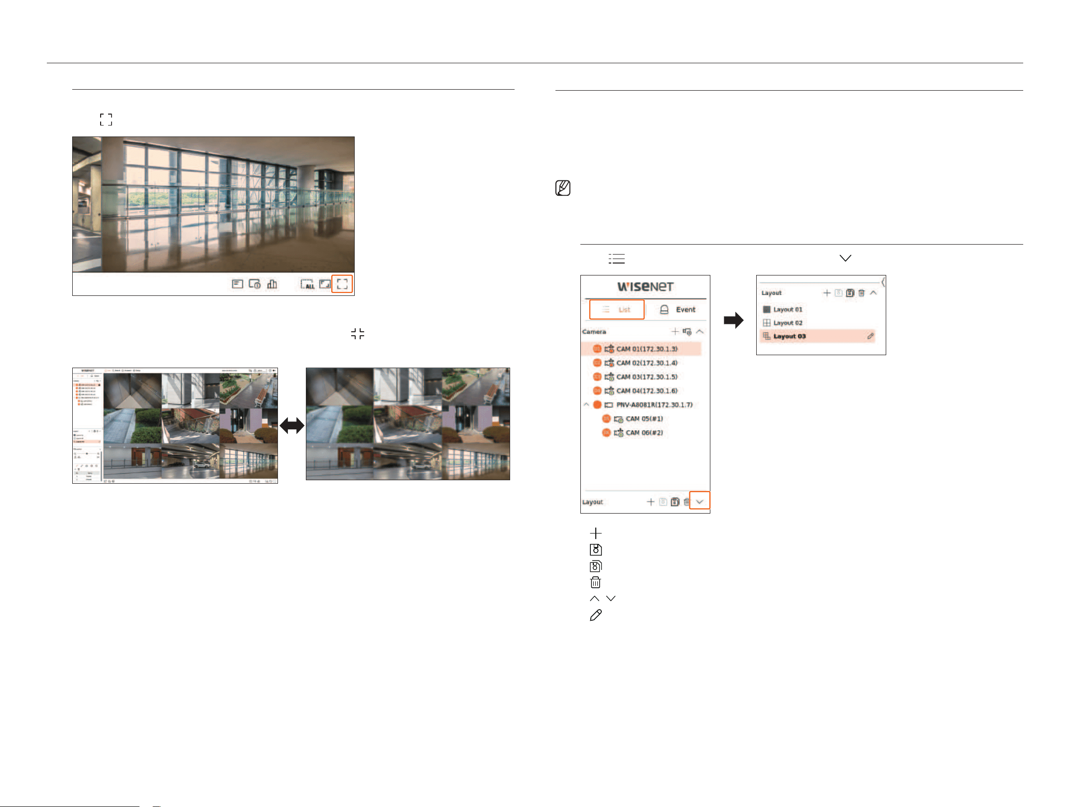
Full Screen mode
You can change to full screen mode, which has no top/bottom/left/right areas of the live screen.
Click <
> at the bottom of the screen.
Changes to full screen mode.
■
To exit full screen, place your mouse cursor over the bottom of the full screen mode and click < >.
general mode Full screen mode
Setting UP the liVe layoUt
This section outlines how to select a series of channels based on their purpose/accessibility and monitor them in a
single layout.
example) Layout "Lobby" - Lobby camera 1, Lobby camera 2, Front entrance camera 2
Layout "VIP" - Directors' meeting room 1, Directors' meeting room 2, Directors' lounge 1, Corridor camera on
the 7th floor
■
After the software upgrade, the previously set layout may be changed. Reset the layout and sequence.
Check layout list
Click <
list > at the top left of the live screen, and then click < > to display the layout list.
●
: Create a new layout.
●
: Save the changed layout.
●
: Saves the selected layout with a different name.
●
: Delete the added layout.
●
/ : Open or close the layout list.
●
: Change the name of the layout.

English _25
add layout and Set name
1. Click <
> to add a layout.
2. Click <
> to set the name for the added layout.
3. Double-click or drag and drop a channel from the camera list to display it on the layout screen. The selected
channel will be displayed in the video window.
■
You can simultaneously assign multiple consecutive channels from the camera list to the video window. Drag the desired channels from the camera
list and drop them on the video window. Depending on the drop location and the number of channels, empty area or the current layout will be
expanded to assign the video.
4. Click <
> to save the set layout.
■
Each layout is saved separately by the user.
■
The layout set on the live screen can also be used for time search and can be searched according to the channel order and channel combination
set by the user. For more information, refer to the "Search > Time Search" page in the Table of Contents.
delete layout
Click <
> after selecting the layout to delete.
■
You cannot delete the default layout.
Change of layout Channel and name
1. Click < > after selecting a layout.
2. Add or delete channels or rename layouts.
3. Click <
> to save the changed settings.
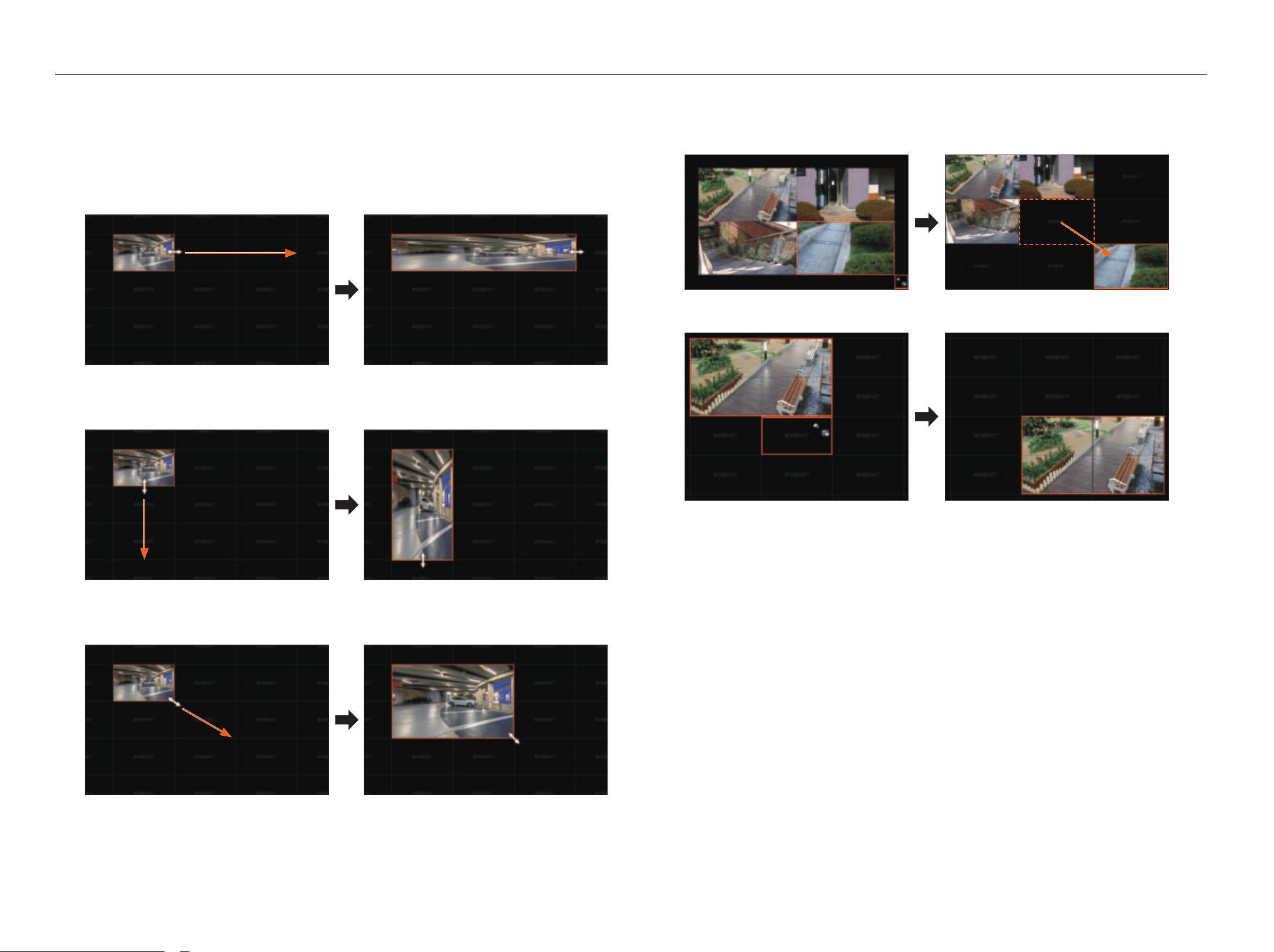
dynamic layout
You can set the size and position of the video assigned to the layout as desired.
■
The dynamic layout function can only be set on the primary monitor.
assigning one Channel
Double-click or drag and drop a channel from the camera list to display it on the layout screen.
The video is assigned to the empty area or depending on the drop location, the current layout will be expanded
to assign the video.
example) When assigning 9 channels to a new layout, the channels are arranged in the order below.
Double-click
assigning multiple Channels at once
Drag multiple consecutive channels from the camera list and drop them into the video window.
Depending on the drop location and the number of channels, the videos will be assigned to empty areas or the
current layout will be expanded to assign the videos.
example) When assigning 9 consecutive channels to a new layout, the channels are arranged in the order
below.
Drag and drop
• liVe
26_ live
live
zooming in and out of Videos
You can enlarge or reduce the video by dragging a corner or vertex of the video in the desired direction.
If you double-click the corner or vertex of the enlarged video area, the video will be reduced step by step.
The video can be enlarged if there is an expandable blank area around the video.
horizontal zoom
Vertical zoom
diagonal zoom
moving Videos
To move the video, click the video and then drag and drop it in the desired location.
Dragging it outside of the layout area will expand the layout area.
The enlarged video can be moved only when there is an empty area that is the size of the video.
English _27
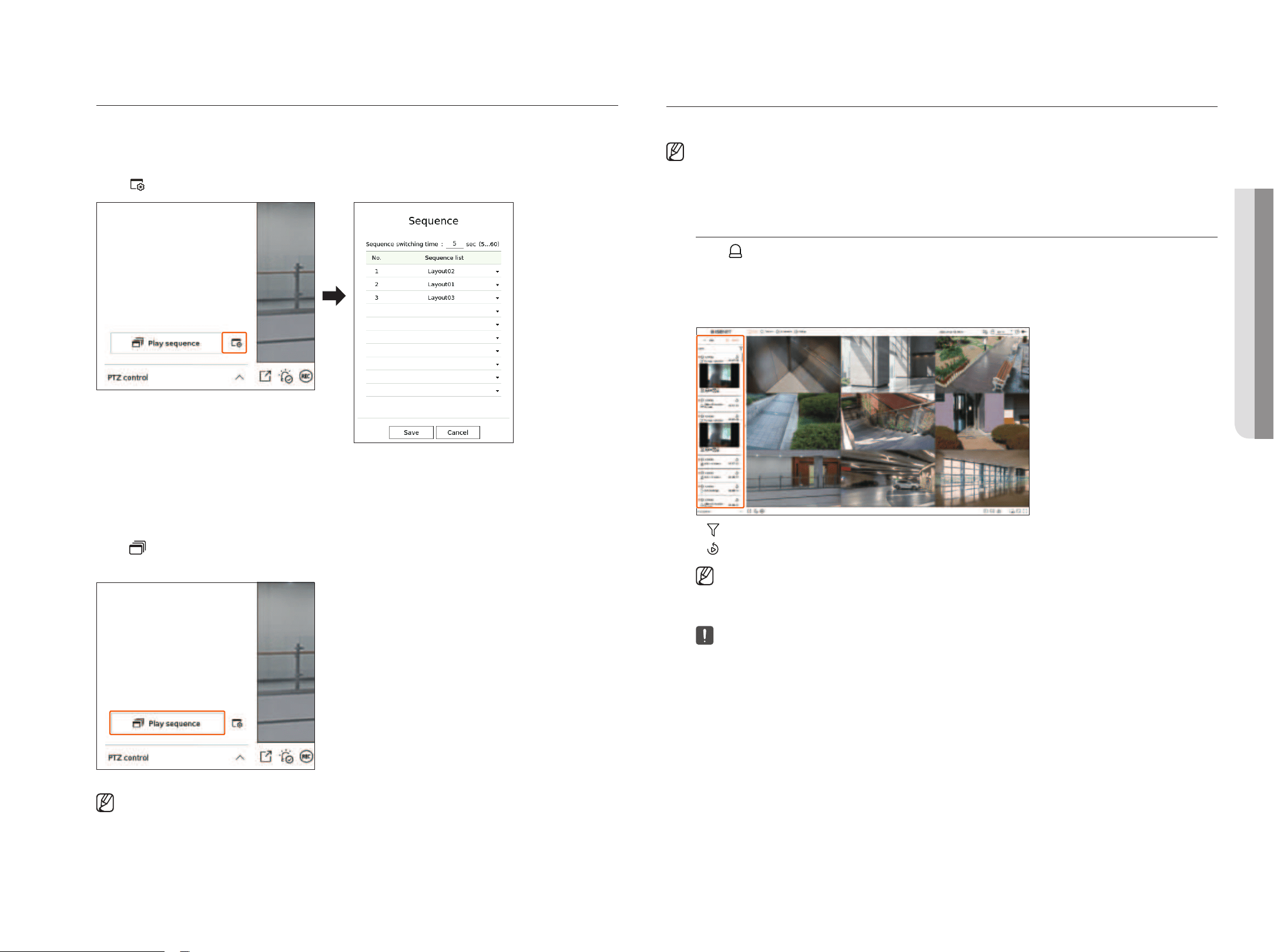
Play layout Sequence
You can automatically switch the layout list to a set time interval to view.
Sequence Setting
Click <
> at the bottom of the layout list to set the sequence.
●
Sequence switching time : Set the switching time of the layout list.
●
Sequence list : Set the layout sequence playback order. You can add the same layout repeatedly.
Play layout Sequence
Click <
Play sequence> at the bottom of the layout list to automatically switch the layout according to the
sequence settings.
■
<Play sequence> is active only when a sequence is set.
real-time eVent monitoring
Real-time events that occurred on the camera can be checked in the live video window and event list.
■
AI events are only available for products that support AI.
■
AI events are displayed only after setting event rules. AI event search may have different settings and operation specifications depending on the recorder
or camera.
Check event list
Click <
event> on the left side of the live screen to display the real-time event list.
■
When new events occur, the list of events will be updated accordingly.
■
The specified channels and events are displayed in the list according to the event rule setup.
For details, refer to the "Setup > Setting the Event > Event rule setup" page in the Table of Contents.
●
: Browses for the event by the desired condition.
●
: Plays the video at the time of the event.
■
When an alarm output occurs, if event recording is set and pre-event time and post-event time are set, event recording is performed before or
after the event according to the set recording method. For more information about event recording settings, refer to the "Setup > Setting the
Recording > Record setup" page in the Table of Contents.
■
The video may be delayed depending on the network condition.
■
The event output can be delayed as the transfer of the alarm event from the network camera takes time.
• liVe
28_ live
live
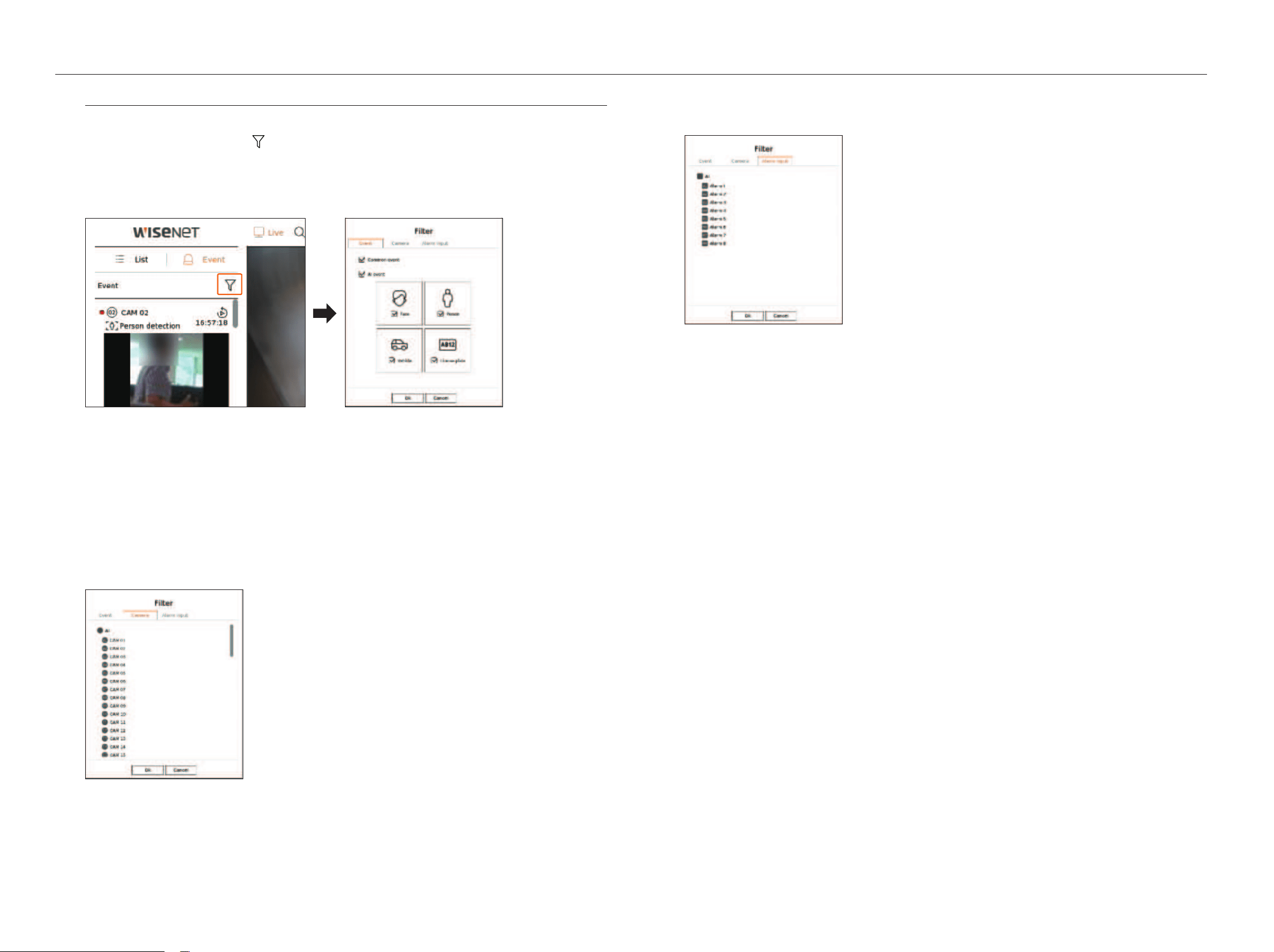
event Search
You can search events by camera, alarm input (recorder), and event type.
To search for a specific event, click <
> to select the event type and camera to browse.
event filter
Displays only selected events in the event list.
●
Common event : Searches for event types that have occurred in general cameras such as motion detection and
IVA.
●
AI event : Searches for AI event types such as face, person, and vehicle.
■
AI events are only activated when an AI camera is connected.
■
AI events are displayed only after setting event rules. For details, refer to the "Setup > Setting the Event > Event rule setup" page in the Table of
Contents.
Camera filter
Displays events for the selected camera only.
alarm input filter
Displays the only events for the alarm input numbers of the selected recorder.
English _29
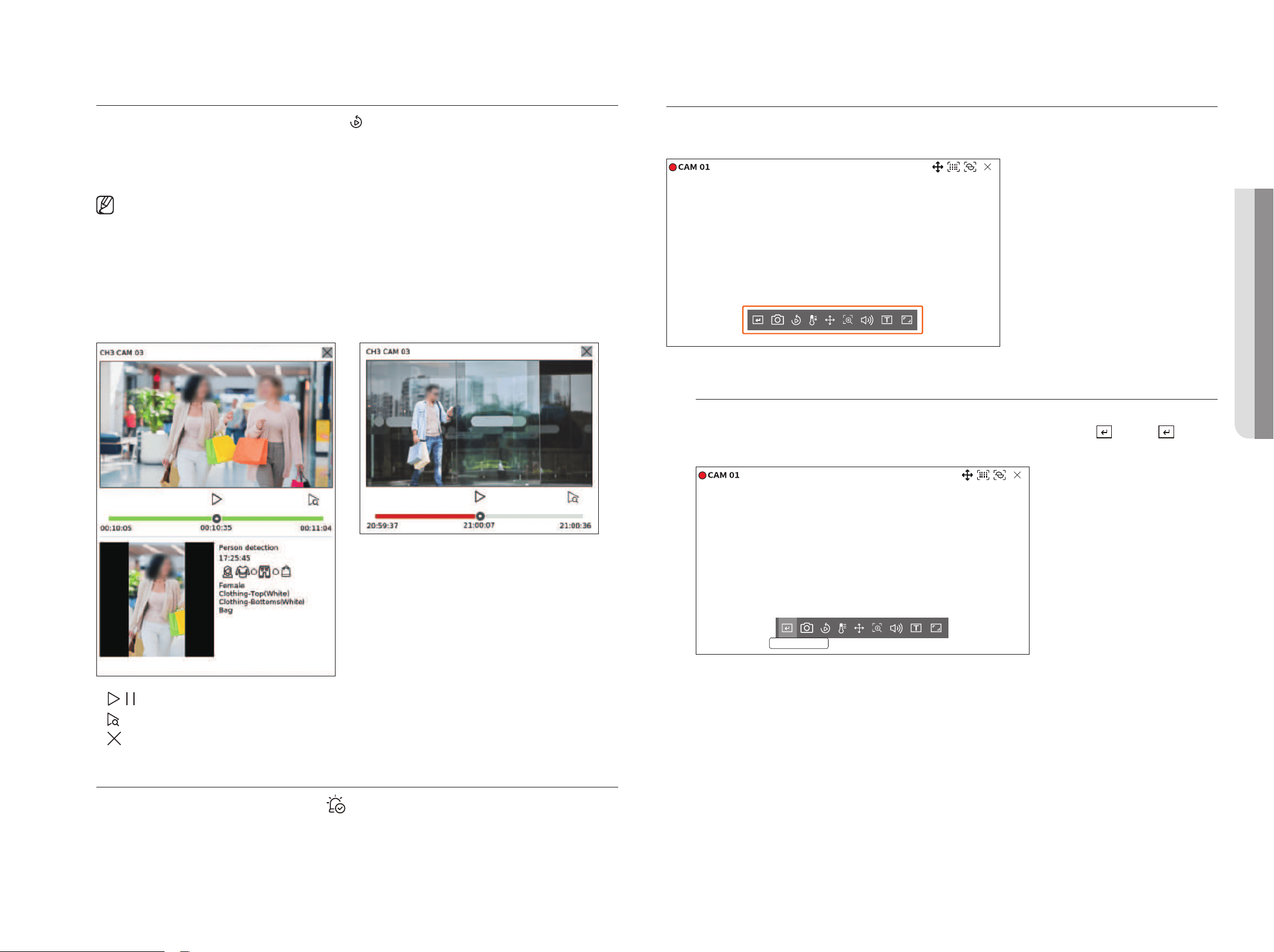
event instant Viewer
Select an event to check from the event list, and click <
> to play the recorded video at the time the event
occurred.
■
Instant viewer can play an event video for 1 minute.
■
For AI events, the best shot and details of the event that occurred are displayed.
■
AI event recognition may have different settings and operation specifications depending on the recorder model or camera.
■
To see AI events, set any of the following options as necessary : See the relevant page for detailed setup method.
– Setup > Event > Event setup > Object
– Setup > Event > Event setup > Mask
– Setup > Event > Event setup > IVA
– Setup > Event > Event rule setup
Common eventai event
●
/ : The video is played/paused.
●
: Moves to the playback screen.
●
: Instant Viewer playback ends.
Stop alarm output
When an event occurs, an alarm can occur. Click <
> at the bottom of the screen to stop the alarm output if
necessary.
For details, refer to the "Setup > Setting the event > event rule setup" page in the Table of Contents.
Camera Video Control
By using the function icon of the video window, you can easily use the functions of capture, video zoom, PTZ camera
and thermal imaging camera. When you place your mouse over the video window, the live screen menu will appear.
manual trigger
If the event action for <manual trigger> is set for the selected channel in the "Setup > event > event rule
setup" menu, the event rule name will be displayed when you hover the mouse over <
>. Click < > to
activate the set event.
Manual trigger 1
• liVe
30_ live
live
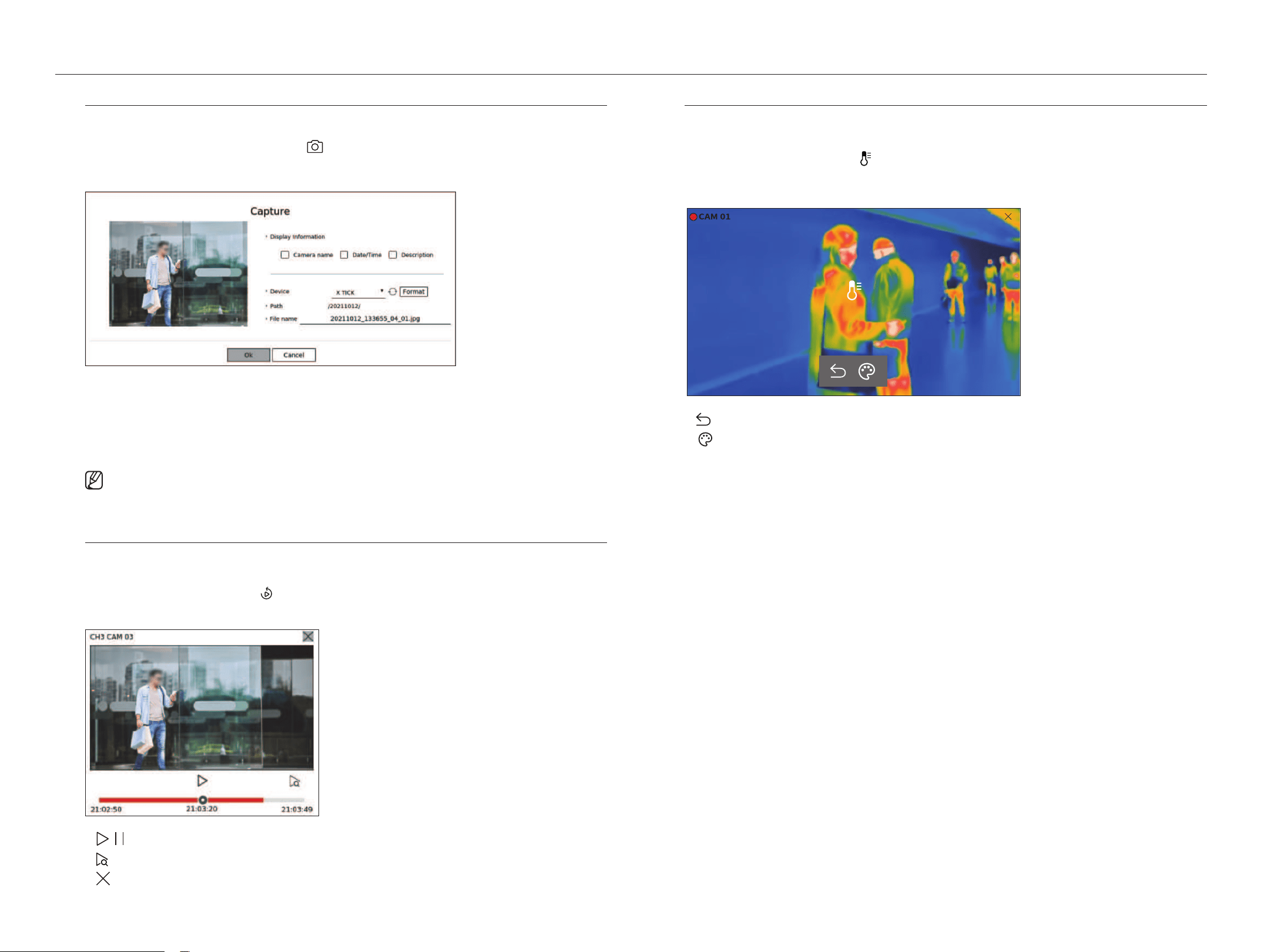
Capture
You can take a screenshot of the current video of a specific channel selected on the live screen.
1. Select a channel to capture video and click <
>.
2. Select the output information to be displayed on the captured screen.
3. Set the device where the screenshot file will be saved and the file name.
■
If you click <Format>, the format confirmation window will appear. Click <Yes > to format the selected storage device.
4. Complete the settings and click <oK> then the image captured from the screen is saved to the selected
device.
■
Camera screen larger than 2 megapixels is captured in Full HD size.
instant Viewer
You can move the video back 30 seconds and play it while live monitoring. Instant viewer plays video from 30
seconds to 1 minute from the current time.
Select the desired channel and click <
>.
The Instant Viewer screen appears.
●
/ : The video is played/paused.
●
: Moves to the playback screen.
●
: Instant Viewer playback ends.
temperature detection mode
For images that support the thermal imaging camera function, you can click the desired point to check the
temperature information.
Select the desired channel and click <
>.
When you place your mouse over the video, the mouse pointer changes to a thermometer shape, and when you
click a specific location on the video, the temperature at that location is displayed next to the mouse pointer.
36.5°
●
: Exits temperature sensing mode.
●
: The color of the video changes according to the temperature color selection.
English _31
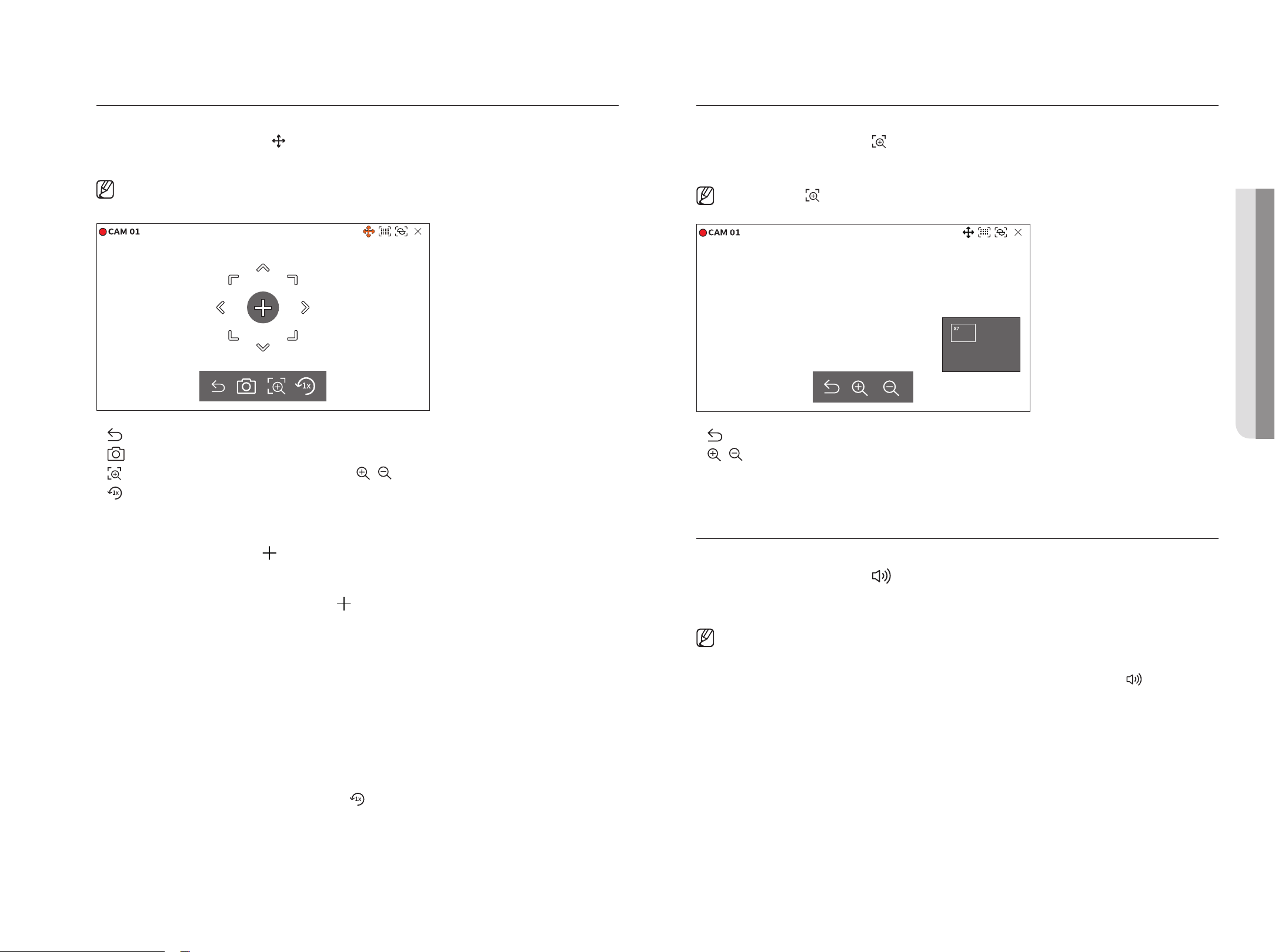
Ptz mode
You can run PTZ control of the selected channel.
Select the desired channel and click <
>.
Enters the PTZ control mode.
■
Depending on the camera, the PTZ control function and speed may be different.
●
: The PTZ mode is closed.
●
: Captures video of the current state.
●
: After clicking the digital zoom icon, you can use < / > to zoom in or zoom out the video.
●
: Returns to the 1x zoom screen.
adjusting the Camera direction
When you rolls over the mouse to <
>, the 8-way key appears, and when the mouse leaves the area of the
direction key, the direction key disappears. You can fine-tune the camera direction by clicking the 8-direction key
once. Keep clicking the arrow keys to move in the desired direction and release the mouse to stop.
To quickly adjust the direction of the camera, click <
> and drag. The screen moves quickly in the desired
direction. You can adjust the screen movement speed according to the drag distance.
moving to the Center of the Screen
Click a specific location on the screen to move the video at that location to the center of the screen.
zooming the Selected area
Drag a specific area of the screen, to move and the selected area to the center of the screen and zoom in.
zooming in and out of images
You can zoom in or out using the mouse wheel. Click <
> to go back to the original size.
zoom in
You can zoom in or out the video via digital zoom.
Select the desired channel and click <
>.
Enters the digital zoom mode.
■
In PTZ mode, click < > to run the digital zoom.
●
: Exits the digital zoom mode.
●
/ : Zooms in or out the video.
●
Minimap : When the video is enlarged 10%, a minimap is displayed. You can quickly check the desired location
in the enlarged video through the mini-map.
audio
You can turn the sound on/off corresponding to the channel in Live mode.
Select the desired channel and click <
>.
Audio output can only be turned on in one channel. The audio output of other channels will be automatically
turned off.
■
If you have configured the audio output settings properly but the audio or voice is not output, check if the connected network camera supports
the sound signal and if you have configured the sound settings as appropriate.
The sound icon can be displayed if the sound signal fails to output from noise.
■
Only the channel where <Audio> is set to <On> in "Setup > Camera > Channel Setup" displays the audio icon ( ) in Live mode that
you can use to turn the sound on/off.
• liVe
32_ live
live
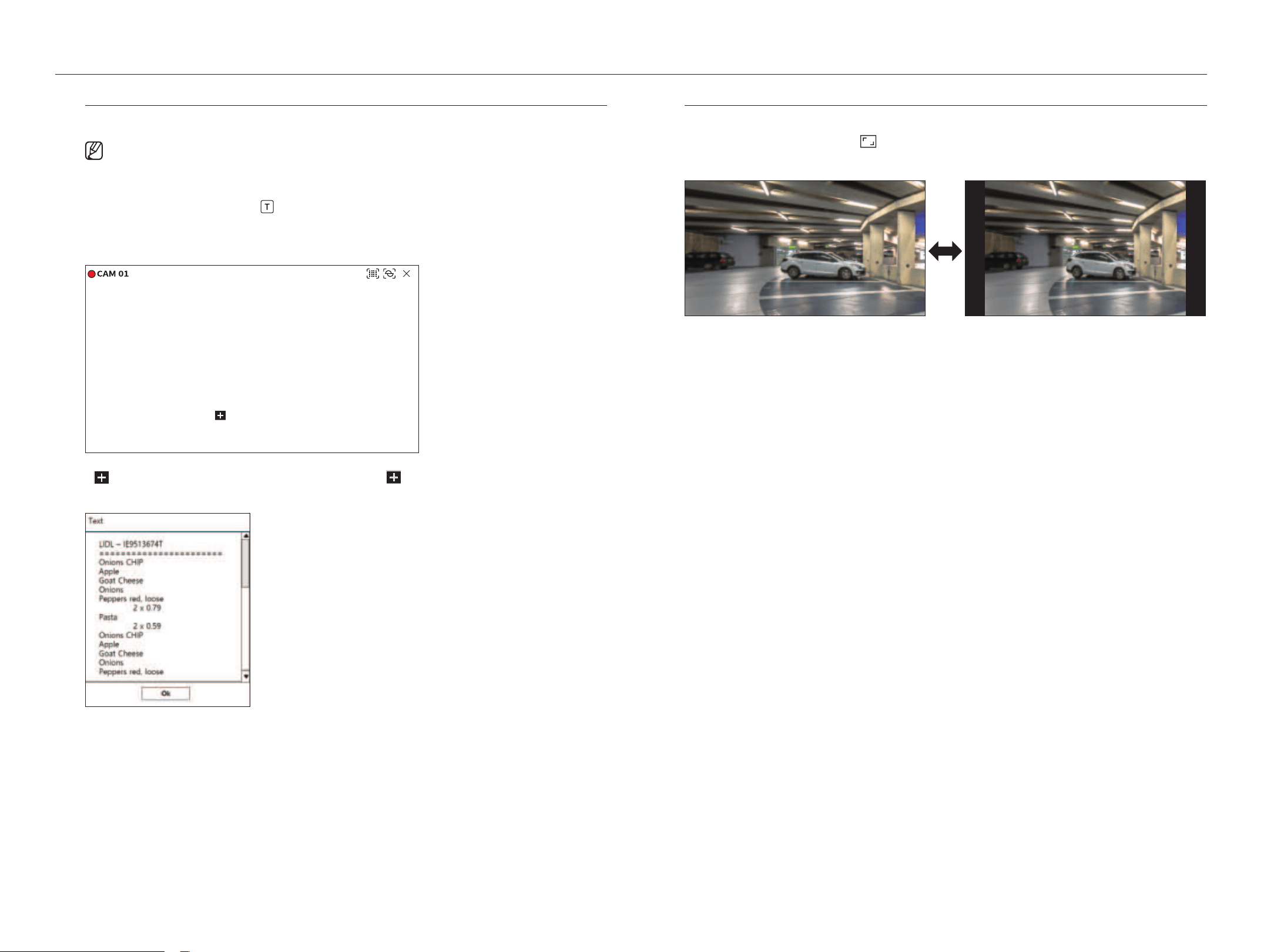
display text
You can monitor texts regarding the sales record received from POS in real time.
■
This is executable when a text device is connected.
■
The Recorder can display text on a live screen when a text device is set. For details, refer to the "Setup > Setting the Device > Tex t" page in
the Table of Contents.
Select the desired channel and click <
>.
When text information occurs, the text information is displayed in the corresponding video window.
Also, when a set text event occurs, the corresponding part of the text is displayed in a separate color.
Onions 3.59
CHIP 2.37
Apple 2.69
Goat 0.79
Peppers red, loose 0.59
2 x 0.79 1.18
Pasta 0.59
2 x 0.59 1.18
========================
TOTAL 3.63
<
> appears when text information crosses the screen. Click < > to display a popup window where you
can check the entire content.
Change Channel aspect ratio
You can change the aspect ratio of each channel.
Select the desired channel and click <
>.
It changes to the actual proportion of the video.
English _33
Ptz Control
With this Recorder, you can configure the settings of a PTZ camera as well as commercial cameras in the market to your
preference.
This is active only if a channel that a PTZ camera is connected to is selected.
getting Started with Ptz operations
The PTZ camera will be activated only if the channel of the PTZ camera is selected. After selecting the desired
channel, click <
> on the live screen menu.
■
This is available only if a PTZ camera is connected and the < > icon is displayed on the screen.
■
Even if the connected network camera does not support the PTZ operations, you can configure the PTZ control settings (if possible) by installing
the PTZ driver (physical device).
■
It only supports a network camera with Hanwha Vision's PTZ function and a camera registered in the ONVIF.
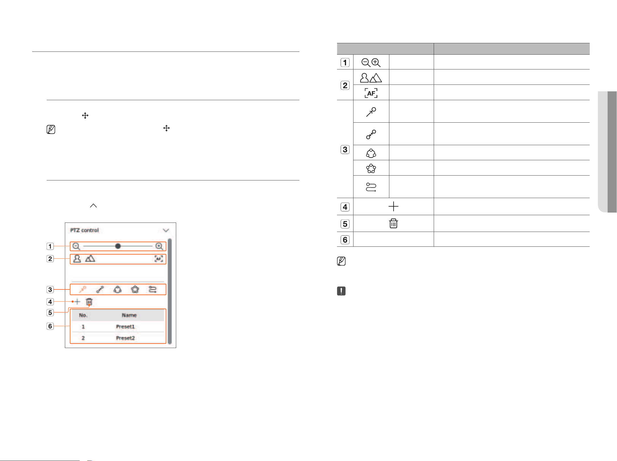
Ptz Control menu
You can use a single PTZ camera to perform the Pan, Tilt and Zoom operations to monitor multiple places, and
configure the custom settings of the presets in a desired mode.
Click <Ptz control
> on the bottom left of the live screen to display the PTZ camera control menu as shown
below.
Item Description
Zoom out/Zoom in Activate the Zoom operation of the PTZ camera.
Near/Far You can adjust the focus manually.
Auto focus You can adjust the focus automatically.
Preset
Set the preset position to move the camera, and then select the desired preset to move to the
set position.
Swing
Swing is a monitoring function that moves between two preset points and enables you to
trace the motion.
Group The group function enables you to group various presets before calling them in sequence.
Tour Monitor all the groups created by a user in turn.
Trace
Tracking remembers the trace of movements that you instructed and reproduces it for your
reference.
The preset you set is saved and displayed in the list.
Deletes the selected preset list.
Preset List Shows a list of saved presets.
■
The PTZ working (active) mark can be active even if the PTZ operation is not available in normal mode. So ensure that you have completed the
PTZ settings before proceeding.
■
Some cameras may differ in the menu title and operation with regard to Swing, Group, Tour and Trace.
■
Even if your network camera supports the function, you can use it only if the button is activated in the PTZ control launcher.
• liVe
34_ live
live
Using digital Ptz (d-Ptz) Function
1. Register a camera that supports the D-PTZ profile.
■
In cameras that support the D-PTZ profile, you can use the D-PTZ function.
2. Both cameras that support general PTZ and cameras that support D-PTZ can control the live image using
some of the <Ptz control> function menus.
■
For more information about the supported functions, please refer to the camera manual.
Preset
Preset is a set of saved data specifying the locations of a PTZ camera. A single PTZ camera can save up to 300
locations.
■
The max. number of presets may vary depending on the number of presets supported by the camera.
to add a preset
1. Select the desired channel and click <
>.
■
The PTZ control screen appears.
2. Use the arrow keys to adjust the camera to the point.
3. Click <
>.
4. If you click <
>, the <Preset setup> window will appear.
5. Click < > to select the Preset Order to set.
6. Enter the Preset name.
7. Click <Save>.
The preset setting will be saved.
■
If you replace a camera that saves your preset settings with a different one, you must configure the preset settings again.
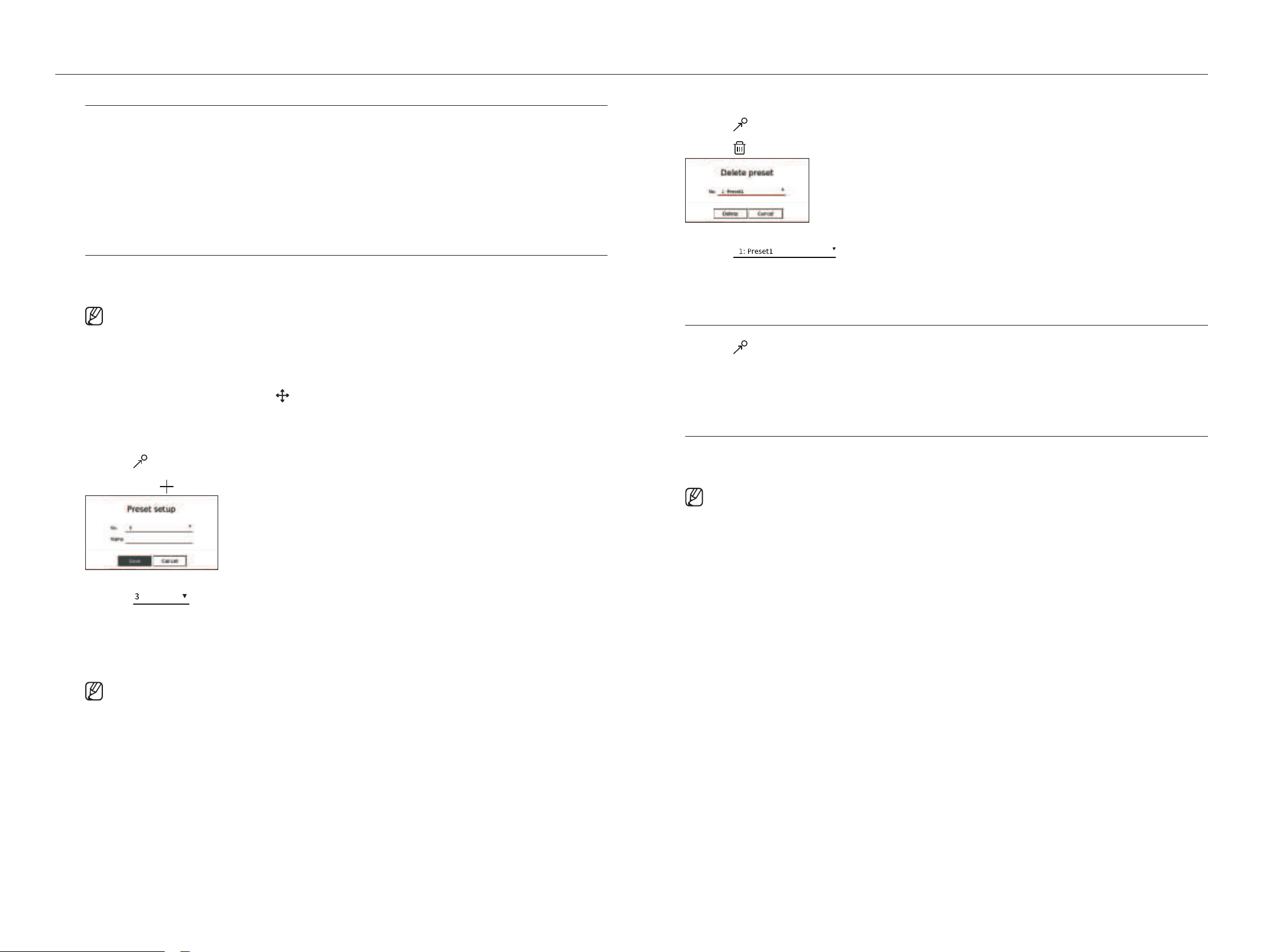
to delete a registered preset
1. Click <
>.
2. Click <
>. <delete preset> window will appear.
3. Click < > to select the preset to delete.
4. Click <delete>. The selected preset will be deleted.
running Preset
1. Click <
>.
2. Click the preset you want to run from the list.
The camera lens moves to the set position.
running Swing (auto pan), group (scan), tour, or trace (pattern)
The running method of each function is the same as the preset operation method. For details on how to use it,
refer to the camera's user manual.
■
Depending on the camera's capabilities, only some features may be available.
English _35
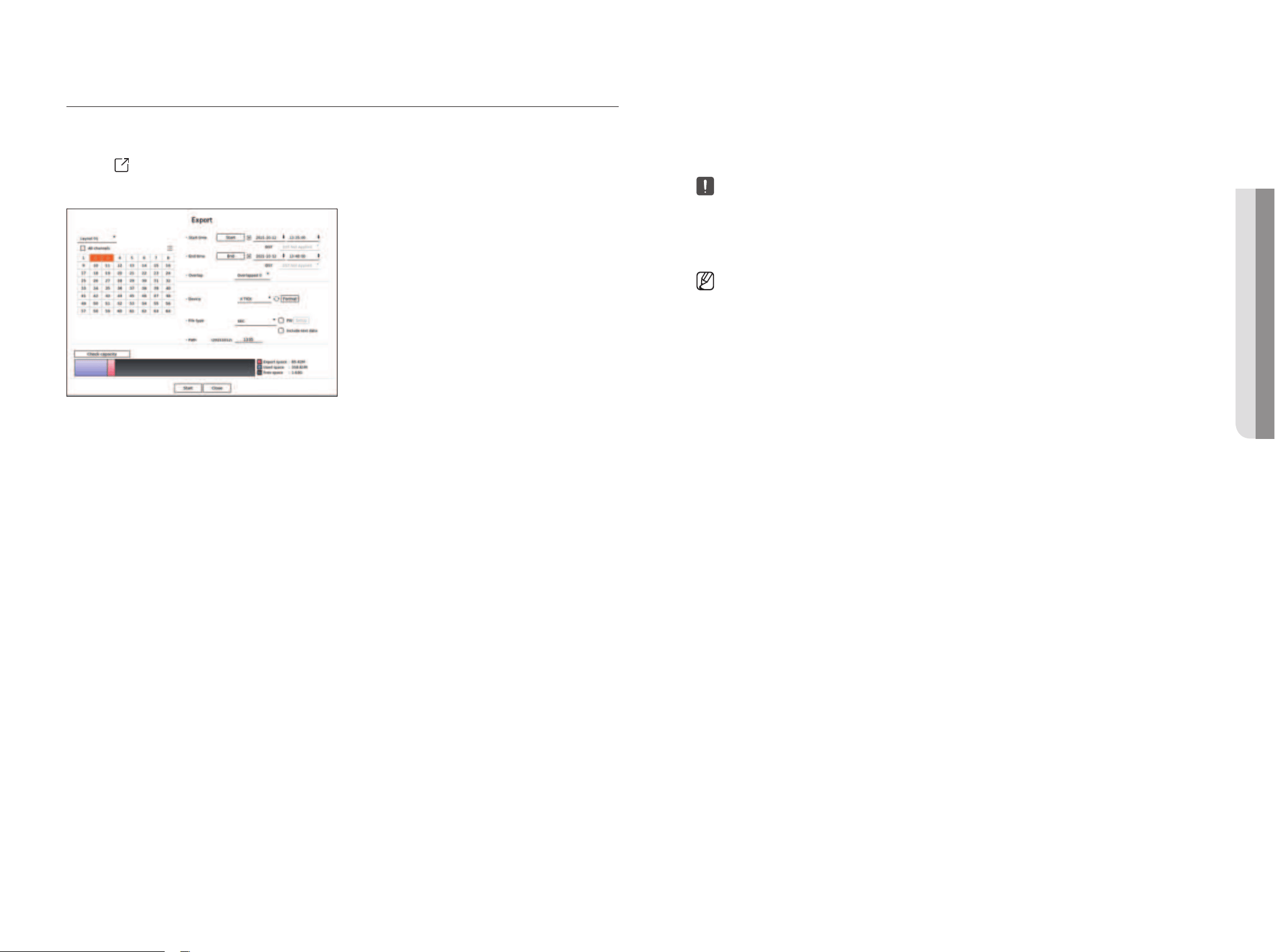
exPorting the reCorded Video
You can search the storage device to be exported and export the recorded video of the desired time by layout or
channel.
1. Click <
> at the bottom of the screen.
2. The export setup screen will appear.
●
Select a layout : Select a desired layout from the layout list.
●
Channel : Select a channel to export.
■
You can select multiple channels. If you select <All channels>, all channels will be selected.
●
Export section : Set the <Start> and <End> time to run the export select to.
– Start : You can set the start time for the export to the desired time.
Click <Start> to set the export start time to the first time the video was recorded.
– End : You can set the end time for the export to the desired time.
Click <end> to set the export end time to the last time the video was recorded.
●
Overlap : Shows a list of overlapping data on a same time according to the number of data.
This is displayed when there are duplicate data in the same channel due to changes in the time or time zone.
■
For more details, refer to the "Setup > Setting the System > Date/Time/Language" page in the Table of Contents.
●
Device : Select a device to export the among the searched devices.
●
Format : If you click <Format>, the format confirmation window will appear. Click <ye s > to format the selected
storage device.
●
File type : Select the export format.
– SEC : You can export in your own file format that can be played directly on your PC. You can play with the viewer
included in the export folder.
■
If you select SEC format, you can choose whether to include "PW Setup" and "Include text data".
– Recorder : You can export to a file that can be played only on the recorder.
– AVI : You can export to an AVI format-compatible with popular media players.
●
Path : Displays the folder location where the export file will be saved. You cannot change the storage folder, only
the file name to be saved.
●
Check capacity : You can check the selected export capacity and the current and remaining capacity of the export
device.
3. After completing the export setup, select <Start>.
■
If there is no device to export, the <Start> button will be deactivated.
■
If you click <Stop> during the export progress, which is the export will be canceled.
4. Click <oK> on the export completion confirmation window to finish.
■
Exporting will not be able to start when a USB with insufficient free space is inserted.
Format the memory stick or delete some of the data on the memory stick to secure adequate storage space.
■
The operation speed of the product may slow down if the export is in which is a progress.
■
You can switch to the menu screen during export progress, but data playback will not be possible.
■
If the export fails, check the current capacity and status to see if the hard disk is connected properly in the "Device > Storage device" menu.
■
If <Hide> is selected while the export is in progress, the screen changes to the upper menu, but the export continues.
• liVe
36_ search
You can search recorded video by various conditions such as time, event, and export.
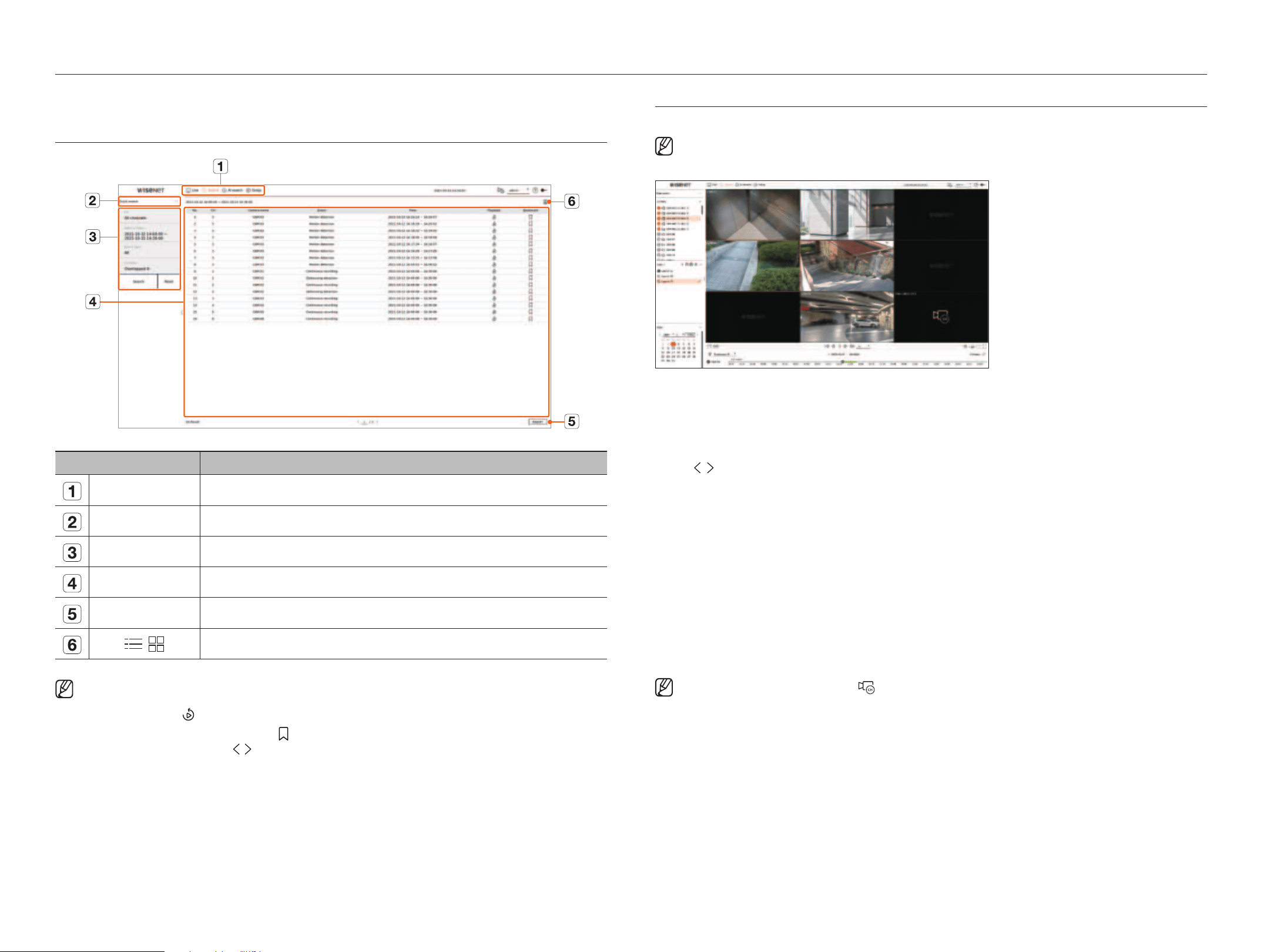
SCREEN LAYOUT OF THE SEARCH
Item Description
Menu Click each menu to go to the corresponding menu screen.
Search menu tab Click the menu tab to display the detailed search menu. Click Search menu to go to the corresponding Search screen.
Search conditions You can set various search conditions, such as date/time/event.
Search results Displays search results.
Export Exports search results to a file.
/
Displays the search results as a list or thumbnail.
■
Click <Reset> to initialize the search conditions and results.
■
Double click on the desired item in the search results list to go to the play screen.
When you click Playback ( ), the video will be played in an instant viewer.
■
You can specify a bookmark by clicking the bookmark ( ) in the search results list. You can check the specified video in the bookmark search menu.
■
If the search results are in multiple pages , you can click to go to the previous/next page. Or, you can click the current page number and enter the
desired page to move.
TIME SEARCH
You can search the recorded data by the desired date and time conditions.
■
The time displayed will be based on the time zone and daylight saving time (DST) applied time zone, so it may be displayed differently depending on
whether the data time zone recorded at the same time and daylight saving time (DST) is applied.
1. Select <Time search> in the <Search> menu.
2. Select a channel to search.
3. Choose a layout.
4. Click
, in the date selection window to select the year and month to search.
Dates with data will be shown in orange and current dates will be shown in orange circles.
5. Select a date to search from the calendar.
The first video of the searched data of the day will be displayed in the video window and the data will be displayed
in the time line.
●
Click <To da y> to search for today's date. Today’s date will be selected.
●
If you click <Overlapped>, you can check the time line by setting the overlapping section by time change.
●
The displayed color differs depending on the type of recording data.
– Light green : Normal recording video
– Red : Event recording video
6. Double click the time of the desired channel to play the recorded video of that time.
■
For unregistered channels (virtual channels), the is displayed in the video window and recording and playback are not possible.
search
English _37
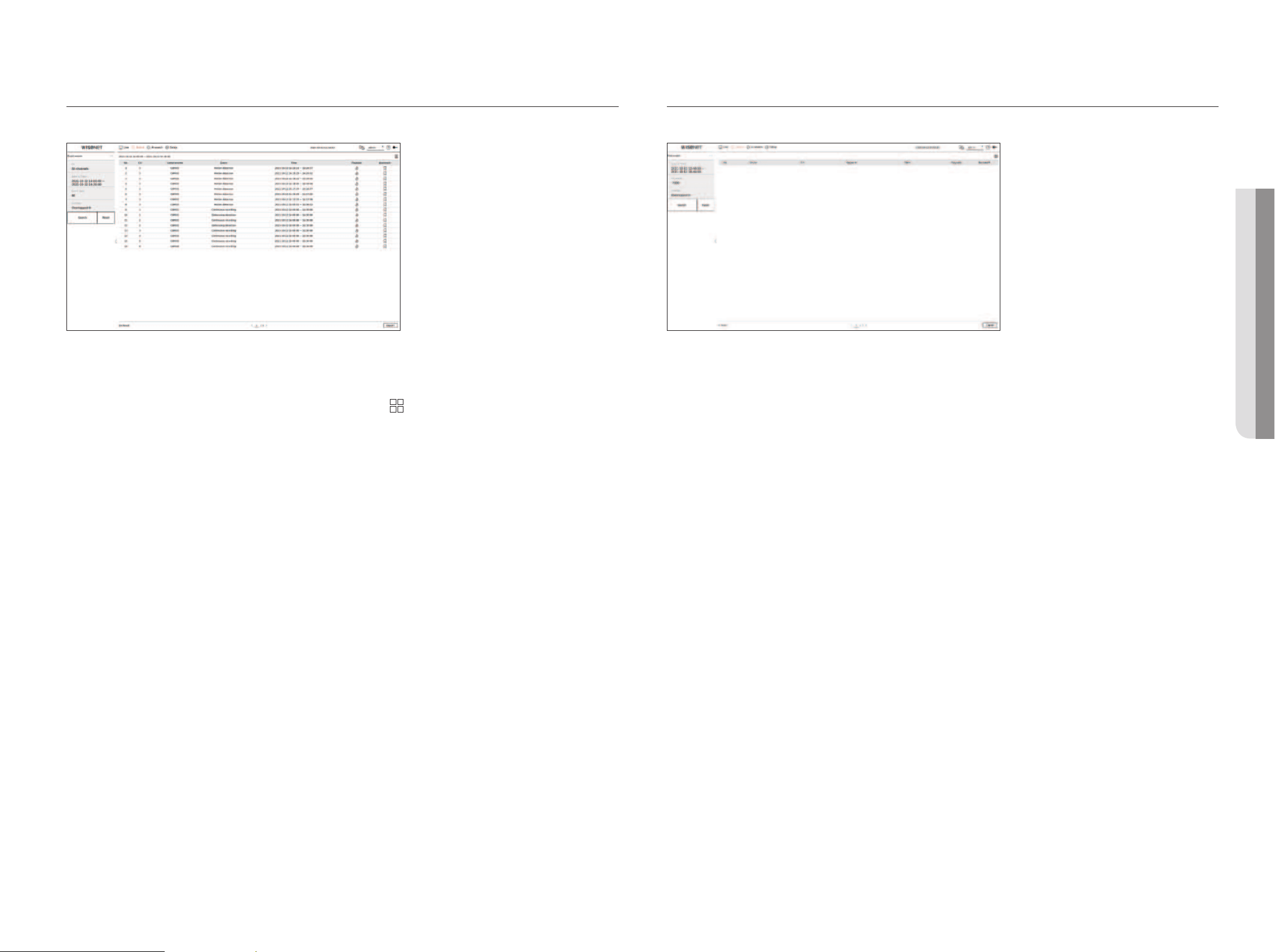
EVENT SEARCH
You can search for various events by channel.
1. Select <Event search> in the <Search> menu.
2. Select a channel to search.
■
If you select a channel to search, you can change the channel display mode by clicking < >. You can select a desired channel by clicking or dragging it
from the channel table, and clicking the channel in the channel list.
3. Select a date and time to search.
■
The search runs only for a maximum of 1 minute, so if the event search section is long, events may not be searched. In this case, reset the section and search
again.
4. Please select an event type. When you click the item, the event type selection window will appear.
■
Event type options : Motion detection, IVA, Face detection, Auto tracking, Tampering detection, Defocusing detection, Fog detection, Audio detection,
Sound classification, Alarm input(camera), Continuous recording, Manual recording, ObjectDetection.Person, ObjectDetection.Face, ObjectDetection.Vehicle,
ObjectDetection.LicensePlate, Mask detection, ShockDetection
■
Event type options may vary depending on the camera model.
5. Select the overlap.
It will be displayed when there is overlapped data in one channel by changing the time or time zone at the selected
time.
6. Click the <Search> button.
The search results list will be displayed.
■
To stop the search, click <Stop> in the search pop-up window. You can check the search results up until now.
●
CH : Displays the channel where the event occurred.
●
Camera name : Displays the camera name.
●
Event : Displays the event type of the recorded video.
●
Time : Displays the start time and end time of the recorded video.
●
Playback : Plays the recorded video with an instant viewer.
●
Bookmark : Specifies a bookmark to the recorded video.
7. If you double-click an item to play in the search list, the recorded video will be played.
TEXT SEARCH
You can search the data input to the POS device connected to the recorder.
1. Select <Text search> in the <Search> menu.
2. Select a date and time to search.
3. Set the keyword item. When you click an item, the keyword setting window appears.
■
You can search with a narrower range by entering specific characters.
●
Text search keyword : Enter the text to search.
●
Match case sensitivity : When checked, the entered characters will be searched with case-sensitivity.
●
Match whole words : When checked, only data that exactly matches the entered character will be searched.
●
Event keywords : You can search for text with preset event keywords. For more information about event keyword
settings, refer to the "Setup > Setting the Device > Tex t > Text Event Settings" page in the Table of Contents.
4. Select the overlap.
It will be displayed when there is overlapped data in one channel by changing the time or time zone at the selected
time.
5. Click the <Search> button.
The search results list will be displayed.
■
To stop the search, click <Stop> in the search pop-up window. You can check the search results up until now.
●
Device : Displays the name of the POS device connected to the recorder.
●
CH : Displays the channel where the event occurred.
●
Keyword : Displays the searched text.
●
Time : Displays the start time of the recorded video.
●
Playback : Plays the recorded video with an instant viewer.
●
Bookmark : Specifies a bookmark to the recorded video.
6. If you double-click an item to play in the search list, the recorded video will be played.
• SEARCH
38_ search
search
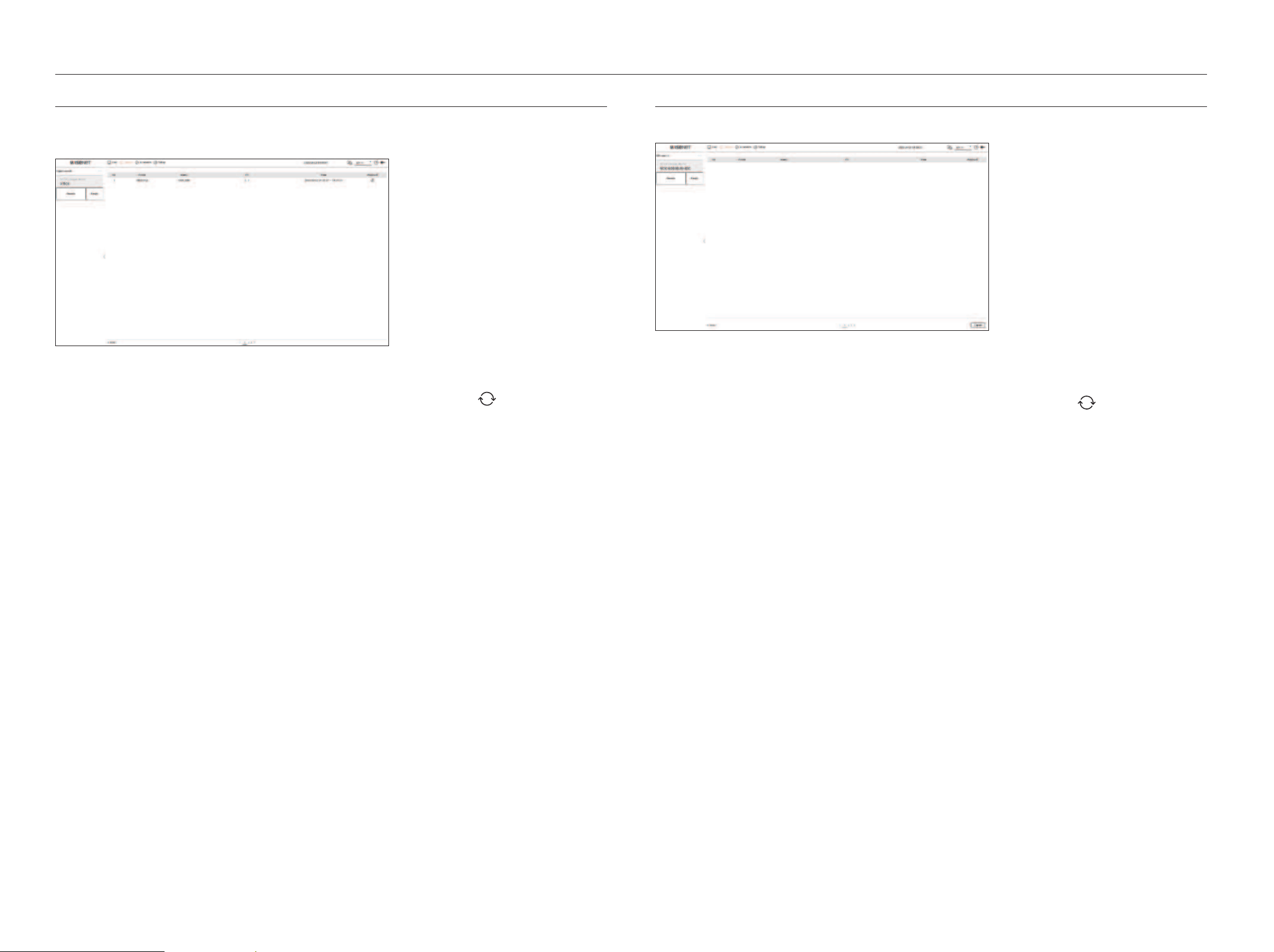
EXPORT SEARCH
You can search the exported data on the connected storage device. Only data saved in recorder file format when
exported will be retrieved.
1. Select <Export search> in the <Search> menu.
2. When you click <Select storage device>, the device search window is displayed. Click <
> to search for storage
device.
3. Click <Search>.
Exported file information will be displayed.
●
Folder : Displays the folder where files are stored.
●
Name :
Displays the folder where files are stored (named by time).
●
CH : Displays the channel of the recorded video.
●
Time : Displays the start time and end time of the exported video.
●
Playback : Plays the exported video with an instant viewer.
4. If you double-click an item to play in the search list, the recorded video will be played.
ARB SEARCH
You can search auto-recovery backup data stored on ARB storage devices.
1. Select <ARB search> in the <Search> menu.
■
For more information about ARB search, refer to the "Setup > Setting the Device > Storage device" page in the Table of Contents.
2. When you click <Select storage device>, the device search window is displayed. Click <
> to search for storage
device.
The model name of the ARB storage device will be displayed.
3. Click <Search>.
The ARB file information stored on the device will be displayed.
●
Folder : Displays the folder where ARB data is stored.
●
Name : Displays the file name stored on the ARB device.
●
CH : Displays the recorded channel.
●
Time : Displays the start time and end time of the backed up video recording.
●
Playback : Plays the recorded video with an instant viewer.
4. If you double-click an item to play in the search list, the recorded video will be played.
English _39
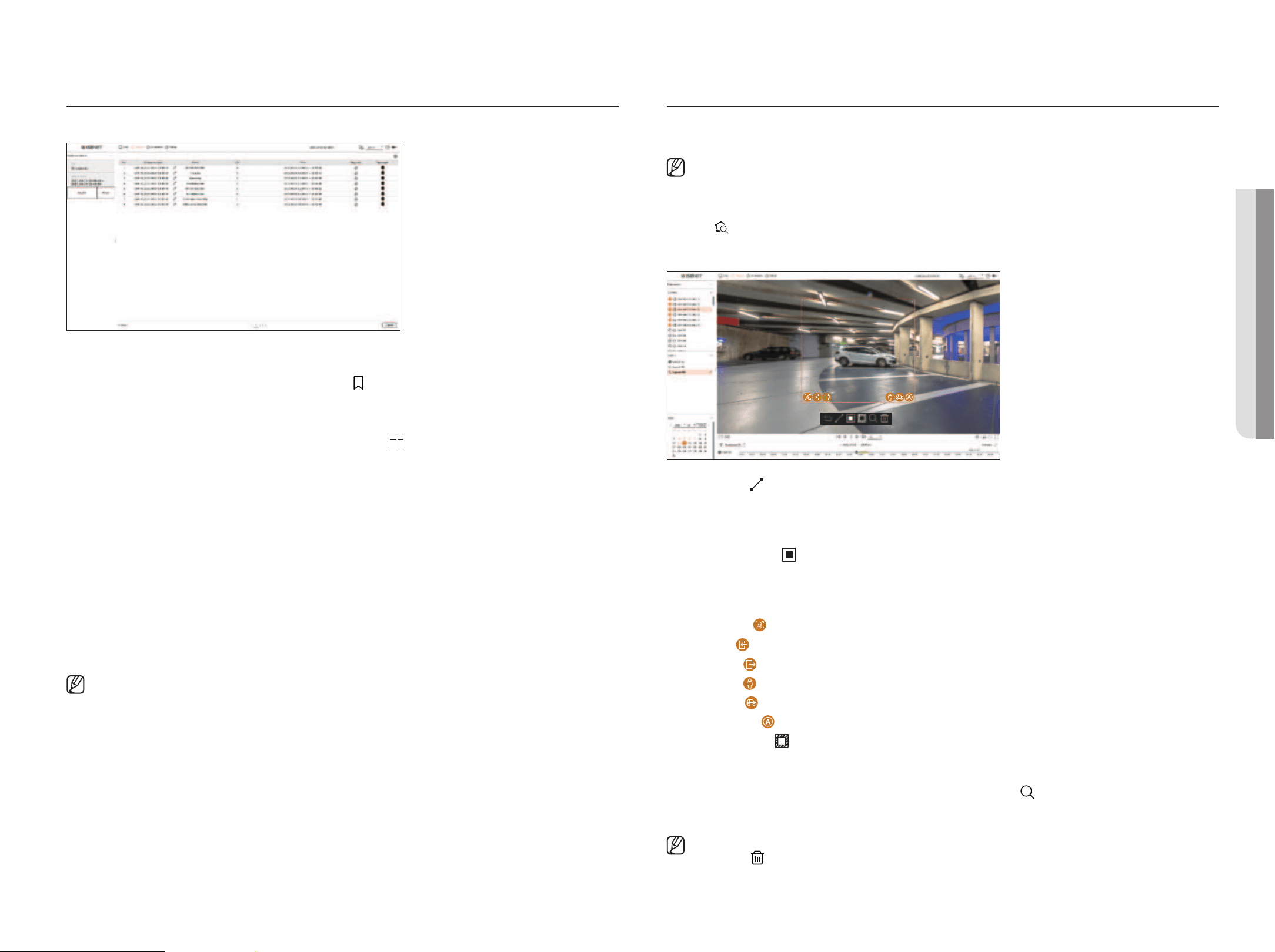
BOOKMARK SEARCH
You can search for bookmarked data.
1. Select <Bookmark search> in the <Search> menu.
■
To search for bookmarks, you need to specify them by clicking the bookmark ( ) in the instant viewer or search results. If no bookmark is specified, search
results will not be displayed.
2. Select a channel to search.
■
If you select a channel to search, you can change the channel display mode by clicking < >. You can select a desired channel by clicking or dragging it
from the channel table, and clicking the channel in the channel list.
3. Select a date and time to search.
4. Click <Search>.
The search results list will be displayed.
●
Bookmark name : Displays the bookmark name you set.
●
Event : Displays the event type of the recorded video.
●
CH : Displays the recorded channel.
●
Time : Displays the start time and end time of the recorded video.
●
Playback : Plays the recorded video with an instant viewer.
●
Bookmark : Displays whether bookmarks are specified.
5. If you double-click an item to play in the search list, the recorded video will be played.
■
Bookmarked images will be stored without being overwritten during repeated recording. However, when the automatic deletion is set, it will be deleted
according to the set period.
■
When the bookmark is released, the video will not be saved. If necessary, before releasing the bookmark, export the video.
■
Up to 100 bookmarks can be specified.
SMART SEARCH
You can search for events by selecting a region of interest, an exclusive region, or a virtual line from a recorded video at
a specific time.
■
To use smart search, you need to set the area of the camera's “Motion Detection" or “I VA” to the entire area. However, if you want to search for cameras
after Wisenet X series, you must select “Enable" in "Event setup > IVA” of the camera. For details, refer to the "Setup > Setting the Event > Event
setup" page in the Table of Contents.
1. Click <
> on the video window menu.
2. Set the smart search area in the video window.
●
Virtual line ( ) : Detects the passing of an object based on the virtual line and direction set on the image. Click
and drag the start and end points of the virtual line to the desired location with the mouse.
– The virtual line can be set in one direction or both directions. If you select the option of the direction of the
virtual line on both sides, it will detect all objects passing in both directions on one virtual line.
●
Region of interest (
) : Uses the entire screen as a non-detection area and specifies a specific area as a motion
detection area. Drag the mouse over the image or take a vertex to set the detection area at the desired location.
– When you set a zone, an event/object option icon will be displayed at the bottom of the zone. Click the icon to
exclude the event/object from the search.
– Intrusion (
) : Detects and searches for moving objects within the area set by the user.
– Enter (
) : Searches by detecting movement from the outside to the inside of the area set by the user.
– Exiting (
) : Searches by detecting the movement from the inside to the outside of the area set by the user.
– Person (
) : Searches for events that include people within the area set by the user.
– Vehicle (
) : Searches for events that include vehicles within the area set by the user.
– All Objects (
) : Searches for events that include all objects within the area set by the user.
●
Exclusive region (
) : Uses the entire screen as a detection area and specifies a non-detection area to exclude
detection of a specific area.
Drag the mouse over the image or take a vertex to specify the non-detection area at the desired location.
3. Set the date and time range to perform the virtual area search and click <
>.
4. When you click an item to play on the time line, the corresponding recorded video will be played.
■
You can set up to 3 areas of interest, exclusion and virtual line.
■
Click Delete ( ) to delete all the set areas.
• SEARCH
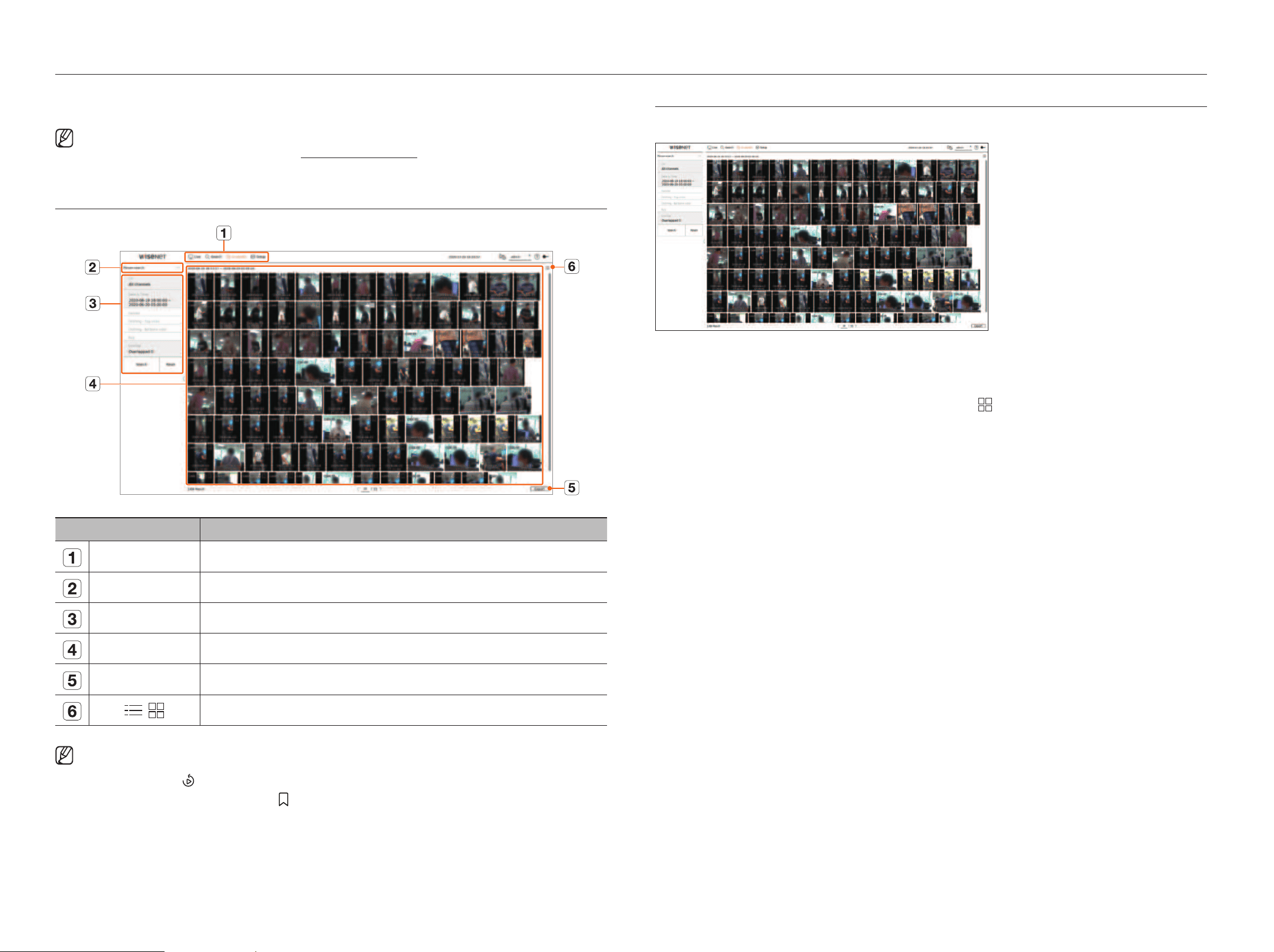
40_ AI search
If there is AI data recorded by the camera, you can search for images in various conditions such as people, faces, and
vehicles.
■
This function is not supported in some models.
■
For products that support the AI search function, refer to the "Functions Supported by Model" page.
SCREEN LAYOUT OF THE AI SEARCH
Item Description
Menu Click each menu to go to the corresponding menu screen.
Search menu tab Click the menu tab to display the detailed search menu. Click Search menu to go to the corresponding Search screen.
Search conditions You can set various search conditions, such as date/time/gender.
Search results Displays search results.
Export Exports search results to a file.
/
Displays the search results as a list or thumbnail.
■
The search options you set will be saved, and click <Reset> to reset the search conditions.
■
Double click on the desired item in the search results list to go to the play screen.
When you click Playback ( ), the video will be played in an instant viewer.
■
You can specify a bookmark by clicking the bookmark ( ) in the search results list. You can check the specified video in the bookmark search menu.
PERSON SEARCH
In the recorded data, you can search for a person by any condition you want, such as gender, top/bottom color.
1. Select <Person search> in the <AI search> menu.
2. Select a channel to search.
■
If you select a channel to search, you can change the channel display mode by clicking < >. You can select a desired channel by clicking or dragging it
from the channel table, and clicking the channel in the channel list.
3. Select a date and time to search.
4. Select a detailed search option.
●
Person search options : Gender, Clothing-Top color, Clothing-Bottoms color, Bag
■
Click the option to display the option selection window. Select the desired search option.
■
If no details are set, all conditions will be selected and searched.
5. Select the overlap.
It will be displayed when there is overlapped data in one channel by changing the time or time zone at the selected
time.
6.
Click the <Search> button.
The search results list will be displayed.
■
To stop the search, click <Stop> in the search pop-up window. You can check the search results up until now.
●
CH : Displays the recorded channel.
●
Camera name : Displays the camera name.
●
Attribute : Displays the recognized search result attributes.
●
Time : Displays the start time of the recorded video.
●
Playback : Plays the recorded video with an instant viewer.
●
Bookmark : Specifies a bookmark to the recorded video.
7. If you double-click an item to play in the search list, the recorded video will be played.
AI search
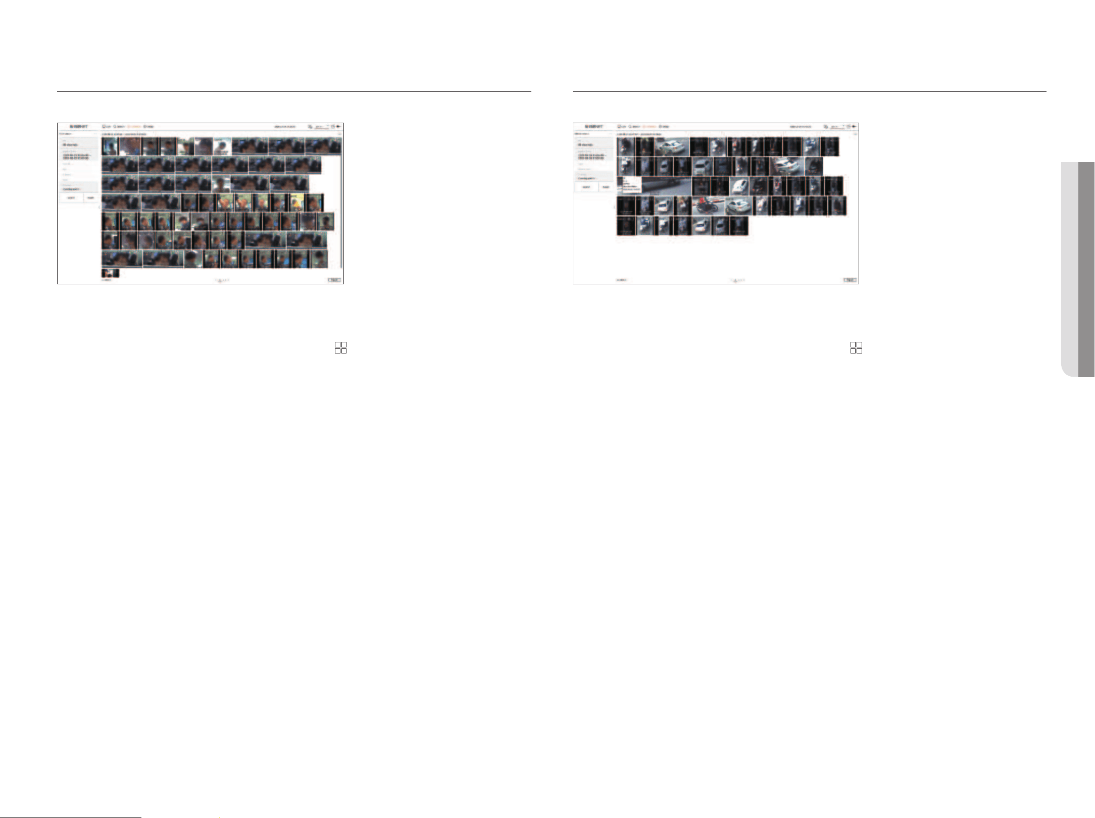
English _41
FACE SEARCH
From the recorded data, you can search faces according to your desired conditions such as gender and age.
1. Select <Face search> in the <AI search> menu.
2. Select a channel to search.
■
If you select a channel to search, you can change the channel display mode by clicking < >. You can select a desired channel by clicking or dragging it
from the channel table, and clicking the channel in the channel list.
3. Select a date and time to search.
4. Select a detailed search option.
●
Face search options : Gender, Age, Glasses, Mask
■
Click the option to display the option selection window. Select the desired search option.
■
If no details are set, all conditions will be selected and searched.
5. Select the overlap.
It will be displayed when there is overlapped data in one channel by changing the time or time zone at the selected
time.
6. Click the <Search> button.
The search results list will be displayed.
■
To stop the search, click <Stop> in the search pop-up window. You can check the search results up until now.
●
CH : Displays the recorded channel.
●
Camera name : Displays the camera name.
●
Attribute : Displays the recognized search result attributes.
●
Time : Displays the start time of the recorded video.
●
Playback : Plays the recorded video with an instant viewer.
●
Bookmark : Specifies a bookmark to the recorded video.
7. If you double-click an item to play in the search list, the recorded video will be played.
VEHICLE SEARCH
You can search the vehicle by setting the vehicle type and color conditions from the recorded data.
1. Select <Vehicle search> in the <AI search> menu.
2. Select a channel to search.
■
If you select a channel to search, you can change the channel display mode by clicking < >. You can select a desired channel by clicking or dragging it
from the channel table, and clicking the channel in the channel list.
3. Select a date and time to search.
4. Select a detailed search option.
●
Vehicle search options : Type, Vehicle color
■
Click the option to display the option selection window. Select the desired search option.
■
If no details are set, all conditions will be selected and searched.
5. Select the overlap.
It will be displayed when there is overlapped data in one channel by changing the time or time zone at the selected
time.
6. Click the <Search> button.
The search results list will be displayed.
■
To stop the search, click <Stop> in the search pop-up window. You can check the search results up until now.
●
CH : Displays the recorded channel.
●
Camera name : Displays the camera name.
●
Attribute : Displays the recognized search result attributes.
●
Time : Displays the start time of the recorded video.
●
Playback : Plays the recorded video with an instant viewer.
●
Bookmark : Specifies a bookmark to the recorded video.
7. If you double-click an item to play in the search list, the recorded video will be played.
• AI SEARCH
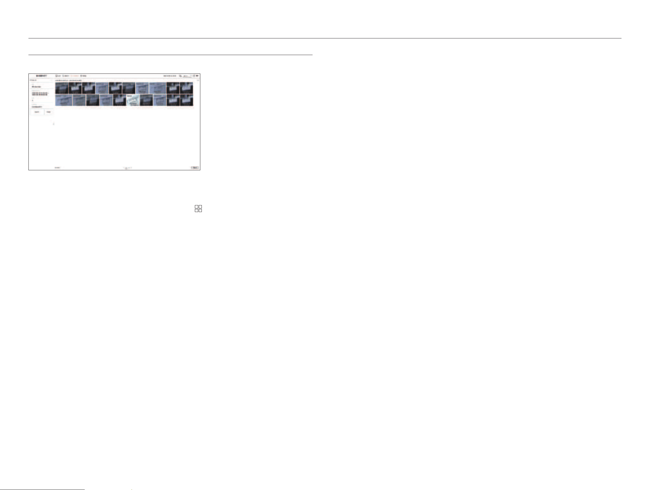
42_ AI search
AI search
LP SEARCH
You can search for vehicle license plates from the recorded data.
1. Select <LP search> in the <AI search> menu.
2. Select a channel to search.
■
If you select a channel to search, you can change the channel display mode by clicking < >. You can select a desired channel by clicking or dragging it
from the channel table, and clicking the channel in the channel list.
3. Select a date and time to search.
4. Select the overlap.
It will be displayed when there is overlapped data in one channel by changing the time or time zone at the selected
time.
5. Click the <Search> button.
The search results list will be displayed.
■
To stop the search, click <Stop> in the search pop-up window. You can check the search results up until now.
●
CH : Displays the recorded channel.
●
Camera name : Displays the camera name.
●
Time : Displays the start time of the recorded video.
●
Playback : Plays the recorded video with an instant viewer.
●
Bookmark : Specifies a bookmark to the recorded video.
6. If you double-click an item to play in the search list, the recorded video will be played.
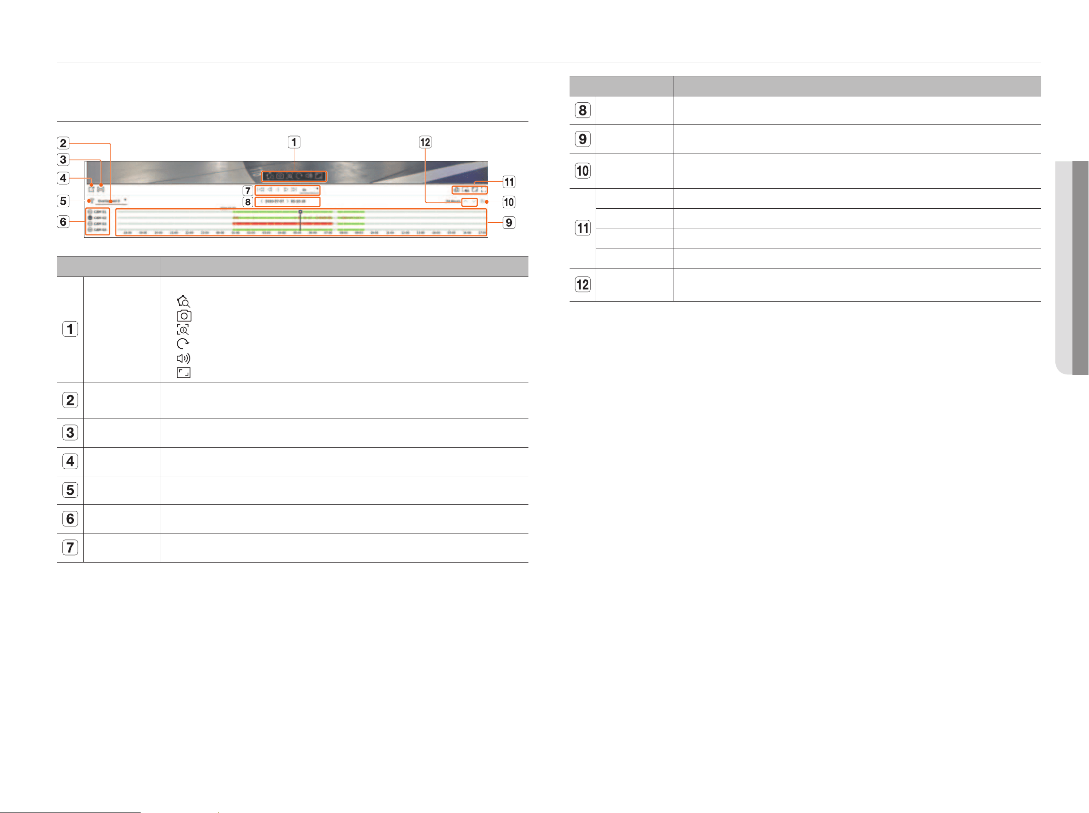
English _43
You can play the recorded data and export the video you want during playback.
SCREEN LAYOUT OF THE PLAY
Item Description
Video control
You can use the video control function.
■
: Runs a smart search by specifying an area in the video window.
■
: Saves the video screen as an image.
■
: Zooms in the selected area on the screen. It only runs on a single split screen.
■
: Displays the image rotated 90 degrees. (This function is not supported in some models.)
■
: Turns the sound on or off.
■
: Changes the video display ratio.
Overlap
The list will be displayed according to the number of overlapped data in the same time zone.
It will appear when a video is overlapped in one channel due to time or time zone change at the selected time.
Export section Turns the export section setting on or off. You can select a start time and end time for exporting.
Export You can export the video of the channel you are playing.
Filter You can filter the event items to see the time line.
Channel The channel and camera name will be displayed.
Playback control You can control video playback.
Item Description
Date/Time Set the date/time.
Time line Move the playback position and display event data.
Show/Hide Channel
You can change the number of channels displayed in the time line.
■
Up to 4 channels of time line can be displayed.
Status You can check the live, recording, and network status.
Remove all tiles Removes all screens from the video window.
Full aspect ratio Change the video display ratio.
Full screen Display the image enlarged to full screen.
Previous/
Next Channel
You can check the time line of the previous/next channel.
play
• PLAY
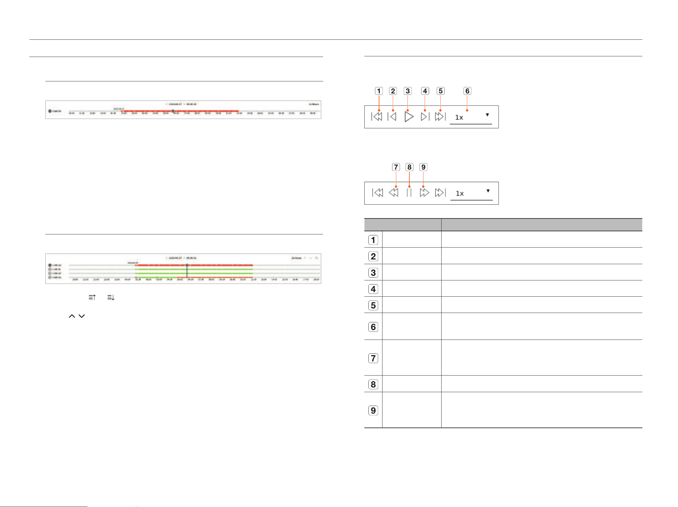
44_ play
play
PLAY SEARCH RESULTS
Time Line Adjustment
You can move the playback position and zoom the time line in and out.
●
Click the desired play position in the time line.
The playback start position will be moved.
■
Click the start point on the left side of the time line to move the playback position to the start point of the first video.
■
Place your mouse over the time line to see the corresponding thumbnail of the recorded video.
●
Click the time line and use the mouse wheel to zoom in or out on the time scale.
It will change in the order of 24 hours-12 hours-6 hours-3 hours-1 hour-30 minutes-15 minutes-5 minutes-1
minutes.
■
The time line magnification of the time line will be displayed at the top right of the time line.
●
To see the time line previous or next zooming in, zoom in and drag the time line left or right.
Open Time Line Channel
You can display the time line of multiple channels.
●
You can click < >, < > to display 1 to 4 channels in the time line. The time line will be displayed as many
channels as selected.
●
Click <
> to move to the previous or next channel.
●
Place your mouse over the time line to see the corresponding thumbnail of the recorded video.
Play Button Name and Function
Paused state
Playback state
Item Description
Previous event Go to the previous event video.
Previous frame Moves backward to the key frame (I-frame).
Playback Play the video.
Next frame Moves forward one frame or more.
Next event Go to the next event video.
Speed
Select the video playback speed.
Speed : x1/8, x1/4, x1/2, x1, x2, x4, x8, x16, x32, x64, x128, x256
Fast backward
It is used for reverse playback.
Speed : -x1/8, -x1/4, -x1/2, -x1, -x2, -x4, -x8, -x16, -x32, -x64, -x128, -x256
■
Depending on the split screen, the maximum speed may be limited.
Pause Pause the video.
Fast forward
It is used for forward playback.
Speed : x1/8, x1/4, x1/2, x1, x2, x4, x8, x16, x32, x64, x128, x256
■
Depending on the split screen, the maximum speed may be limited.
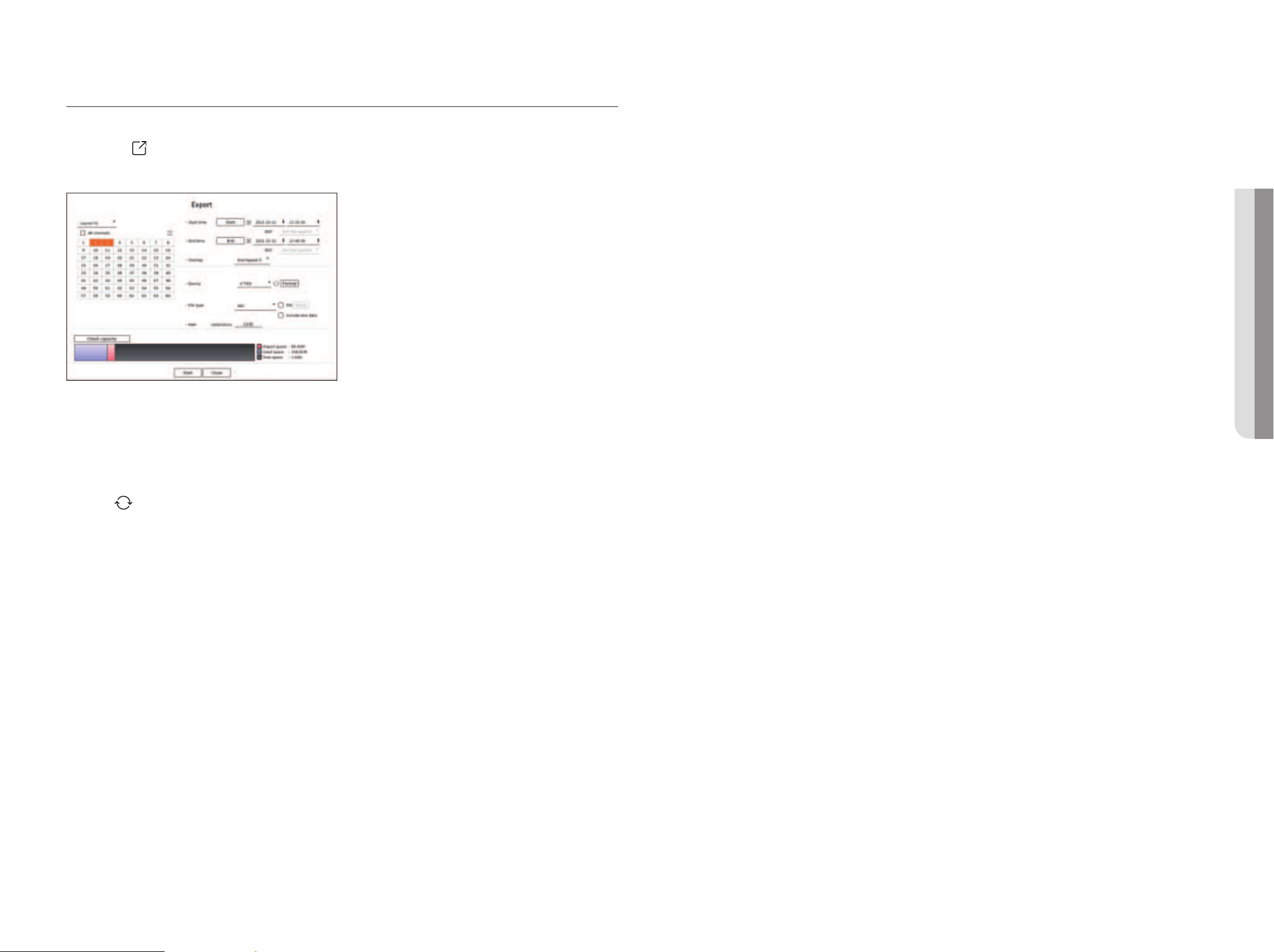
English _45
SEARCH RESULTS EXPORT
You can export the search results to a file.
1. Click the <
> button.
2. Select a layout and channel to export.
3. Select a start date/time and an end date/time.
■
If you changed the time zone of the recorder, select whether to apply DST.
4. Select the overlap.
It will be displayed when there is overlapped data in one channel by changing the time or time zone at the selected
time.
5. Click <
> to select a storage device.
■
If you click <Format>, the format confirmation window will appear. Click <Yes > to format the selected storage device.
6. Please select a storage file type.
– SEC : You can export in your own file format that can be played directly on your PC. You can play with the viewer
included in the export folder.
■
Click <Setup> to set a password for the exported video.
■
If you check <Include text data>, you can save text data in the exported video.
– Recorder : You can export to a file that can be played only on the recorder.
– AVI : You can export to an AVI format-compatible with popular media players.
7. Check the path to save the file to be exported. Only the file name to be saved can be changed.
8. Click <Check capacity> to check the storage capacity.
9. Click <Start>.
When the export is complete, a confirmation window will be displayed.
10. Click <OK> to exit.
■
If you click <Stop> while exporting, the export action is canceled.
• PLAY
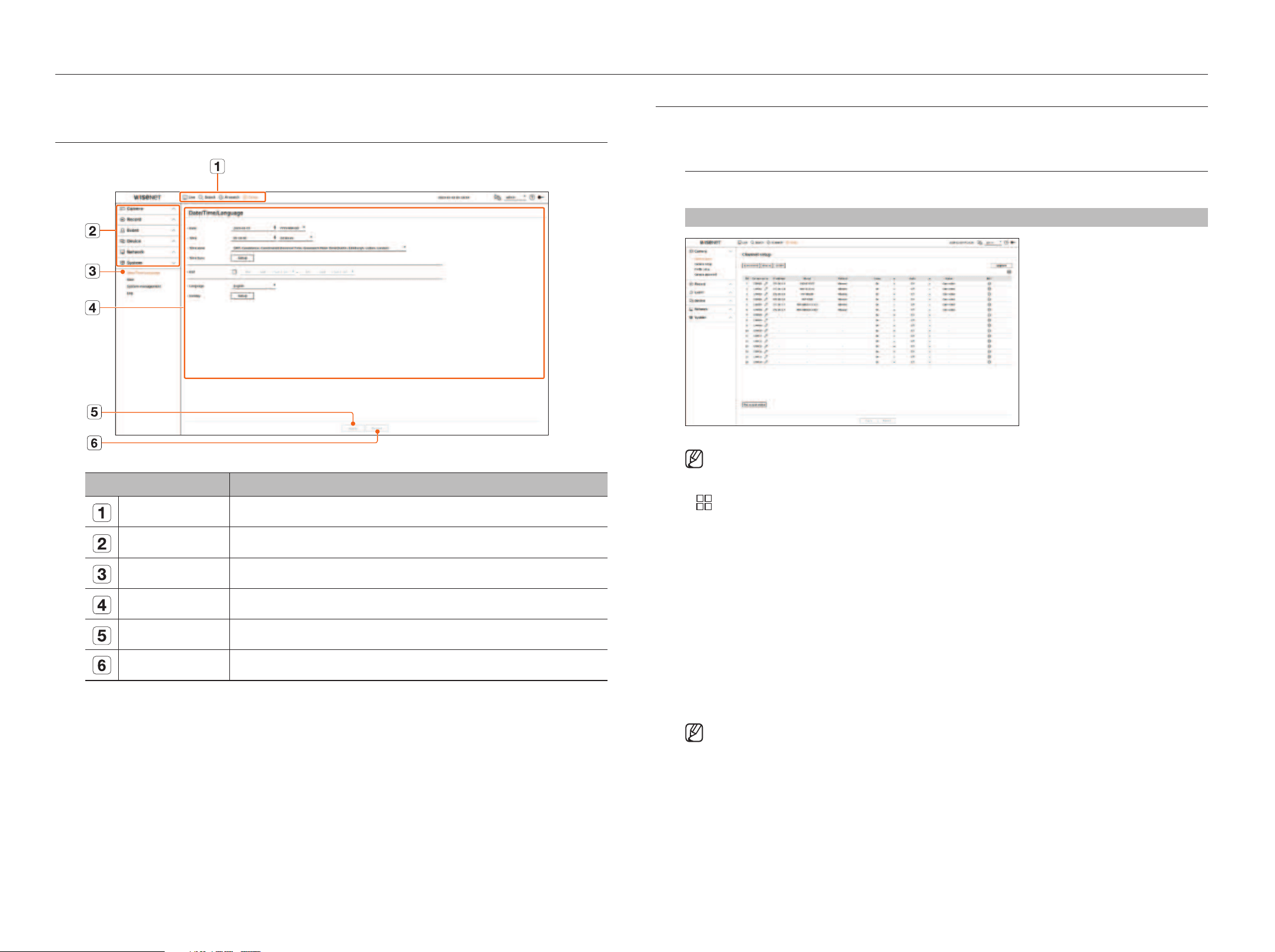
46_ setup
setup
Sets the camera, recording, event, device, network, and system environment.
SCREEN LAYOUT OF THE SETUP
Item Description
Menu Click each menu to go to the menu screen.
Top menu list Configure the settings or select a parent item to change the existing settings.
Sub-menu list Among the sub-menus of selected parent menu, select a desired item to set.
Detailed Menu Click desired item's input field to change and enter a desired value.
Apply Apply the modified settings.
Revert Revert to the settings used before the change.
SETTING THE CAMERA
You can access to the channel setup, camera settings, and profiles and camera password-related settings.
Setting the Channel
You can register a network camera for each channel and make connection between.
Setup > Camera > Channel setup
■
When you register a camera for the first time in the "Setup > Camera > Channel setup" menu, the camera setup screen will be
displayed. For details, refer to the "Getting Started > Camera Setup" page of the table of contents.
●
: Displays the camera of the corresponding channel as a list or a thumbnail.
■
Camera searched with ONVIF does not provide previews.
●
Camera name : Provide a camera Name. You can enter up to 15 letters including spaces.
●
IP address : Display the IP address of a network camera.
●
Model : Show the camera model name.
●
Protocol : Show the protocol information of a registered network camera.
●
Video
– On/Off : You can turn ON/OFF the selected channel's camera. If the camera video is turned off, a blank screen
is displayed.
– Covert1 : Shows information other than the video of the selected channel.
For privacy protection, it does not display the video while the recording continues.
– Covert2 : Shows nothing but an empty screen while the recording continues.
■
If the channel is set to
<Covert1
> or
<Covert2
>
mode, the channel's sound is not hearable.
However, the channel's sound is recorded if its Audio setting is set to
<
On>
, even the sound is not heard in Live mode.
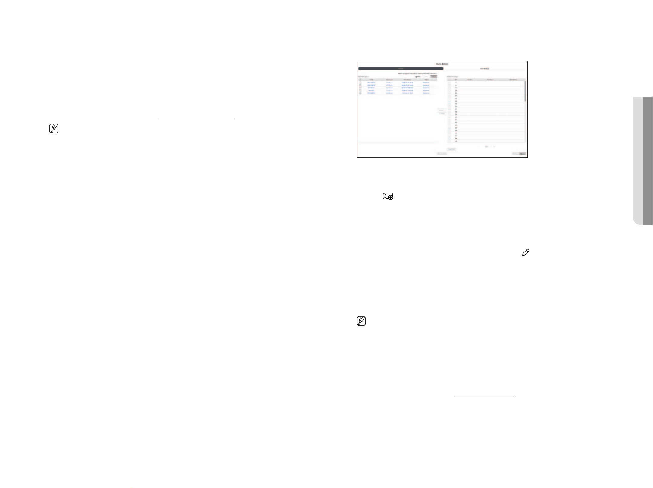
English _47
●
Audio
– If set to <On>, you can turn the audio of the channel ON/OFF on the Live screen.
– If set to <Off>, the channel's audio is off on the Live screen and not recorded.
●
Status : Display the connection status.
●
Edit : You can change the connection information of the camera.
●
Upgrade : You can check the camera’s version, upgrade version, and status and upgrade it.
●
PoE output status : For products that support PoE, this shows the current status of the connected PoE.
For products that support PoE, refer to the "Functions Supported by Model" page.
■
If you cannot register a camera after initializing the system, check the network setting. As the system is initialized and the network setting
is reset, the camera's network bandwidth will be different from the product's network bandwidth, so it will be impossible to register a
camera.
Automatic Registration of Network Cameras
1. In the <Channel setup> field, click on the <Auto detect> button.
2. <Auto detect> window appears.
■
Click < > in the camera list on the live screen to automatically search and register the camera.
3. Select a camera to register in the <Searched camera> list and press the <Register> button.
You can check the selected camera in the <Camera to register> list.
■
An already registered camera will be marked in blue in the list.
■
If you search for the camera again or if the IP is an old IP that was not assigned by the DHCP server (such as 192.168.1.100), then press the
<Refresh> button to check if a new IP has been assigned.
■
<Status> shows the camera authentication status. In the <Auth failed> state, click < > to enter the camera ID and password.
■
Click a header at the top of the list to sort the list according to that header.
4. To change the IP address of the camera, select the desired camera from the <Camera to register> list and
press the <Change IP> button.
5. Click <Next> at the bottom of the screen to set the registered camera channel.
6. Press the <Register> button on the lower right of the screen to register the selected camera.
■
If you register a camera using a user account—not admin account—the camera features may be limited.
■
When you change the camera ID/password in the camera web viewer, if the camera is already registered in Recorder, you also have to
change the camera ID/password information registered in Recorder.
■
When the camera is factory reset, it defaults to the ID and password set in "Setup > Camera > Camera password".
■
If the camera's ID and password have already been set, the registered information matches the ID and password set in the "Setup >
Camera > Camera password". (up to 3 sets)
■
Wisenet camera is registered via Wisenet protocol while a third party camera is registered via ONVIF protocol.
■
A device running a DHCP server should never be connected to a PoE port or a camera setup port. (e.g. router)
■
If your camera uses its own power supply unit, you need to manually register or auto-register the camera.
■
For products that support PoE, refer to the "Functions Supported by Model" page.
• SETUP

48_ setup
setup
Registering a Network Camera Manually
1. In the <Channel setup> field, click on the <Manual> button.
2. <Manual registration> window appears.
■
You can register the camera manually by clicking <+> from the camera list on the live screen.
3. Select a channel and protocol used to connect to a camera.
The input items may differ depending on the selected protocol.
●
Wisenet : Wisenet camera's protocol can be used.
●
ONVIF : Means the camera supports ONVIF protocols. When connecting a camera that its name cannot be
found from the list, select <ONVIF>.
■
When a camera is registered with ONVIF, if the difference in system time between the camera and recorder is 2 minutes or more, you
won’t be able to register it. In this case, synchronize the camera and recorder time.
●
RTSP : Comply with RFC 2326, one of "Real Time Streaming Protocol (RTSP)" for real-time streaming.
4. If you select <Wisenet> protocol, set the following items.
●
Model : Select a camera model.
– Unknown : Select when the camera model cannot be identified.
– Wisenet Camera : You can register Hanwha Vision's cameras and encoders.
– Wisenet Multi-Channel : You can register Hanwha Vision's multi directional cameras and multi-imager
cameras. A multi-channel camera is a camera that has multiple camera modules in one body. Auto-
registering your camera to Recorder lets you register multiple channels at once. However, if you want to
manually register it, you need to register one channel at a time.
●
Address type : Select an address type of the camera.
■
The supported address type may differ depending on the type of the connected product.
– IPv4/IPv6 : Used to provide the IP address of the camera manually.
– Wisenet DDNS : This is available only if the camera is registered with the Wisenet DDNS(ddns.
hanwha-security.com) server. Provide the registered domain for DDNS ID.
Example) http ://ddns.hanwha-security.com/snb5000 ; provide "snb5000" for Wisenet DDNS
– URL : Used for URL address input.
■
The DDNS specs supported by each camera can be checked in the user manual of the corresponding camera.
●
IP address : Provide the IP address of the camera.
●
Device port : Provide the device port of the camera.
■
Depending on the camera type, some device ports will not be supported.
●
HTTP/HTTPS : Provide the HTTP/HTTPS port of the camera.
■
If TLS is enabled, you can set the HTTPS port.
●
TLS : You can set whether to use TLS.
●
ID : Provide the ID of the camera that you want to register.
●
Password : Enter the password of the camera to be registered.
●
Details : You can set the streaming mode.
5. If you select <ONVIF> protocol, set the following items.
●
IP type : Select the IP type of the camera.
●
IP address : Enter the camera's IP address.
●
ONVIF port : Enter the port number when the address type is IPv4 or IPv6.
●
TLS : You can set whether to use TLS.
●
Channel : Enter the channel to register the camera.
●
ID : Enter the camera ID.
●
Password : Enter the camera password.
●
Details : You can configure the authentication mode and streaming mode.
6. If you select <RTSP> protocol, set the following items.
●
URL : Enter your RTSP access address. For more information, see your camera user manual.
●
ID : Enter the camera ID.
●
Password : Enter the camera password.
●
Details : You can set the streaming mode.
■
If ONVIF or RTSP protocol is selected, you can set the streaming mode in the Details section.
– TCP : The connection to network camera operates in the RTP over TCP mode.
– UDP : The connection to network camera operates in the RTP over UDP mode.
– HTTP : The connection to network camera operates in the RTP over TCP (HTTP) mode.
– HTTPS : The connection to network camera operates in the RTP over TCP (HTTPS) mode.
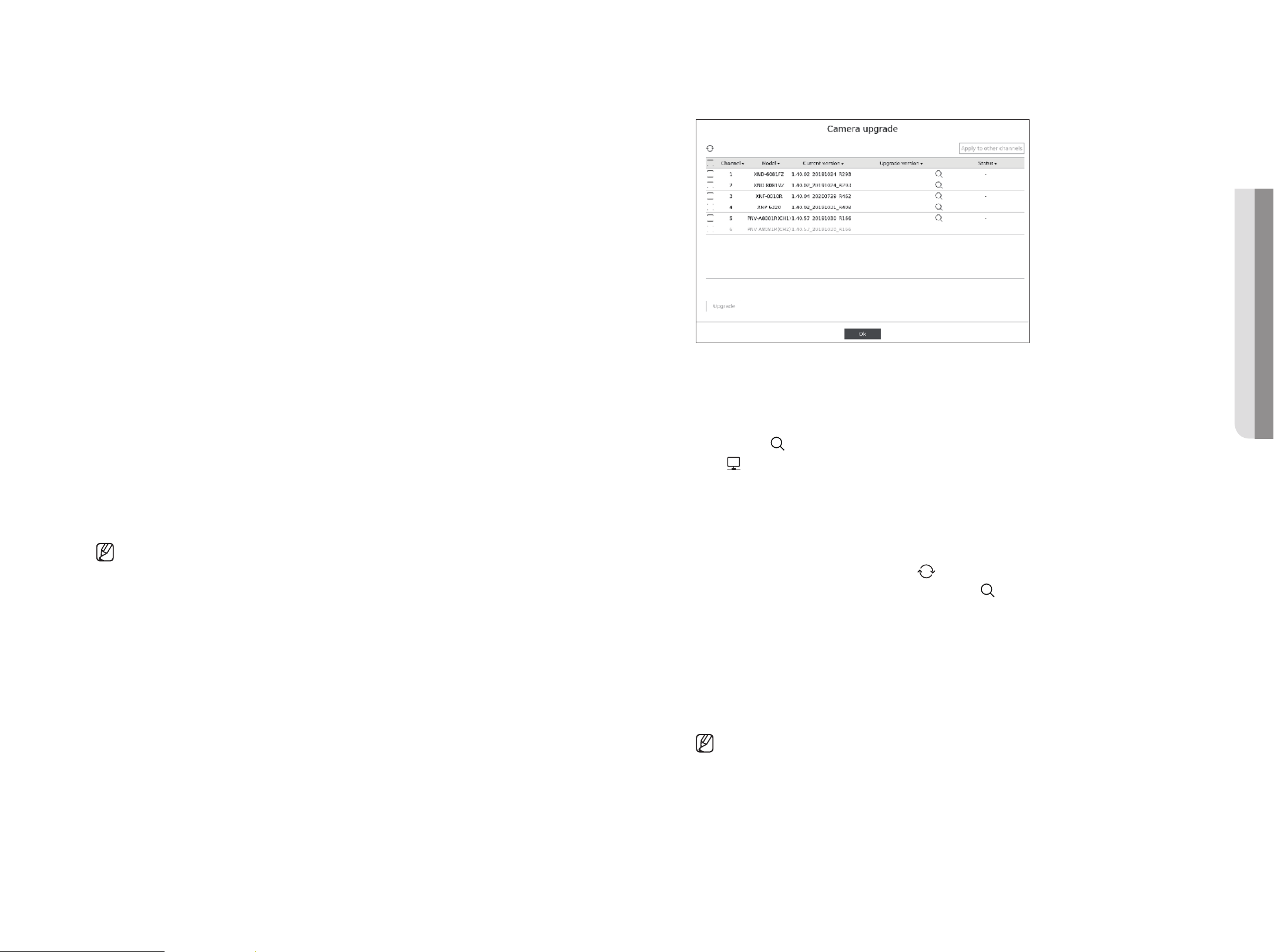
English _49
If you want to check the error details of camera registration
If you failed to register a camera, the reason for the failure will be displayed.
●
Connection failed due to unknown error. : This message appears if the camera has failed to be registered
due to unknown connection status.
●
Due to the camera account locking, access has failed. : When you enter a wrong ID/password 5 times to
login to the camera account, this message is displayed.
Try to log in again after 30 seconds. If the same message appears, you may need to check whether someone
has tried to access your camera account from the outside.
●
Connected successfully. : This message appears if the camera is connected successfully.
●
Incorrect model information. Provide the correct model information. : This message appears if the model
information provided for registering the camera is incorrect.
●
Authentication has failed. : This message appears if the ID or password provided for registering the camera is
incorrect.
●
Connection has failed due to excessive concurrent users. : This message appears if the concurrent user
count exceeds the upper limit.
●
Connection has failed due to incorrect HTTP port information. : This message appears if the HTTP port
number of the camera is invalid.
●
Connection has failed. Unknown connection status. : This message appears if the camera has failed to be
connected due to a unknown error.
●
User Model Modification : When registering a new camera, it is named according to the device's default if
user set the model to <Wisenet Camera>. In case if automatic registration fails, user can change the model
name of camera to be registered.
To edit camera profile
To change profile, refer to the “Setup > Setting the Camera > Setting the Profiles" page in the Table of
Contents.
■
In case of Recorder, if you set 3 different profiles for live, recording and network profile, one camera will produce video streams accordingly,
having different stream formats. Especially, note that the live profile may vary depending on the used screen split mode.
■
For cameras, if applied with one profile only, the produced frame rate is fixed as the profile specifies; if applied with multiple profiles,
produced video stream's frame rate is not guaranteed. For example, if applied with 2 profiles of 30fps, the camera may transmit streams at
20fps.
Delete Network Camera
1. Click <Delete> in the <Channel setup> field.
2. When the delete window appears, select the camera channel to delete.
■
Click <All channels> to select cameras for all channels.
3. Click <OK> to delete the camera of the selected channel.
Network Camera Firmware Upgrade
●
Channel : Displays channel information.
●
Model : Displays the camera model information.
●
Current version : Displays the current camera firmware version.
●
Upgrade version : Displays the firmware version to upgrade.
– Press the <
> button to select the firmware manually within the USB.
– <
> indicates an upgrade via a remote server.
●
Status : Displays the status of the ongoing upgrade (upgrading, successful, failed).
1. Press the <Upgrade> button in the <Channel setup> field.
2. Displays the upgradeable channel list among the connected cameras.
■
If newer firmware exists on the remote server, the upgrade version is displayed, and the check box is automatically selected.
■
If you do not see the upgrade version, you can press the < > button to get the upgrade version information from the server.
■
Connect a USB camera with camera firmware to the recorder and press the < > button to check and select the firmware file in the USB.
■
Select a channel and press the <Apply to other channels> button to apply the firmware to other channels connected to the same model at once.
3. Check the box of the channel you want to upgrade.
4. Click the <Upgrade> button. The camera firmware upgrade starts.
■
You can move to another menu while upgrading.
■
You can stop the upgrade by clicking the <Stop> button during the upgrade.
■
When the upgrade is completed, you can see the result in the popup window.
■
Firmware upgrade is available only for channels connected with the Wisenet protocol and the camera’s administrator account.
■
If the upgrade version is not displayed even though the camera’s firmware is out of date, check the network settings.
■
If there are more than 50 firmware files in the top USB folder, the file may not be scanned.
■
The system may reboot if USB is disconnected from the recorder during an upgrade via USB.
■
Video data of the channel connected to the camera to upgrade may not be recorded.
■
Do not format the HDD until the upgrade is complete. The upgrade may fail.
• SETUP
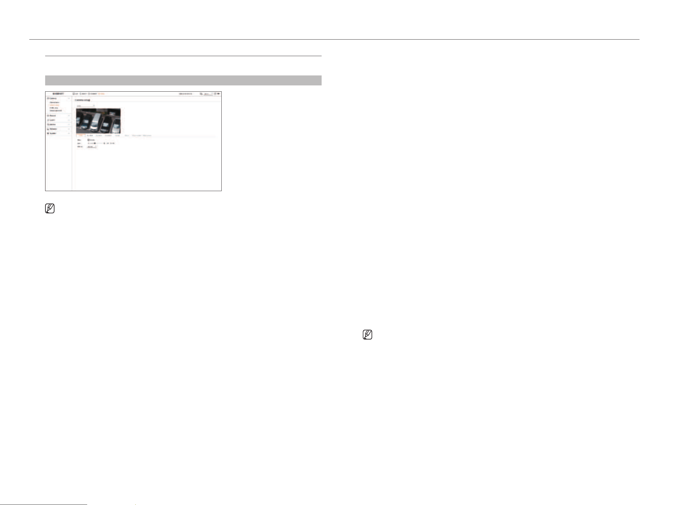
50_ setup
setup
Setting the Camera Functions
You can set the camera while viewing the live video of the selected camera.
Setup > Camera > Camera setup
■
You can use this feature in the following cases :
1. A camera connected to Wisenet protocols.
2. A camera connected with admin privileges.
■
For more details on camera settings, refer to the camera user manual.
Settings and operational spec vary depending on each camera.
■
This function is not supported in some models.
SSDR
If there is a significant difference between the dark and the bright areas, increase the brightness of the dark areas
to maintain the level of brightness of the entire area.
You can set Mode, Level, and D-Range.
Backlight
You can view both bright and dark areas.
You can set Mode, WDR level, WDR black level, and WDR white level.
Exposure
You can adjust the exposure of your camera.
You can set brightness, shutter, SSNR, Sens-up, iris/lens, and AGC.
●
Brightness : Adjusts the brightness by setting the exposure value.
●
Shutter : Adjusts the brightness by controlling the camera shutter speed. If you select shutter, you can set
among the items below.
– Auto : Adjusts the brightness automatically, controlling the shutter speed of the camera.
– ESC (Electronic Shutter Control) : Adjusts the brightness automatically, controlling the shutter speed
according to the surrounding brightness.
– Manual : Adjust the brightness by manually selecting the maximum/minimum shutter speed of the camera.
– Anti-flicker : Reduces flickering in video when screen blur occurs due to different lighting and frequency of
attention. The shutter speed cannot be set when the anti-flicker frequency is selected.
●
SSNR : Adjusts the brightness by reducing noise and minimizing afterimages even in dark places.
●
Sens-up : Automatically adjusts the shutter speed according to the brightness of the current light.
●
IRIS/Lens : Adjusts the brightness by automatically or manually adjusting the camera IRIS and lens.
●
AGC : Adjust the brightness by amplifying the camera's electrical signal when images are shot in the dark.
Day/Night
You can change the mode to adjust the color and contrast.
You can set Mode, Dwell time, Negative color, Duration, Alarm input, Switching brightness, Simple focus after
Day/Night, and Activation time (color).
●
You can select the day/night video display mode in <Mode>.
– Color : Images are always displayed in color.
– B/W : Images are always displayed in B/W
– Auto : The video will be displayed in color in normal environments and in B/W at night.
– External : Displays a color or B/W video by linking an external infrared camera to the alarm in terminal. Set
the alarm in item when selecting the <External>.
– Schedule : Controls the video output mode by directly inputting the color video activation time. Click
<Setup> and enter the activation time.
Special
You can set DIS (Digital Image Stabilization), Defog, and Defog level.
Focus
You can adjust the focus of you camera's video.
You can set Focus, Zoom, Simple focus, and Initialize focus.
Video rotation
You can set flip/mirror modes and hallway view.
Privacy area
You can set an area to be hidden in the camera image range to protect privacy.
After selecting whether or not to
use the privacy setting, you can set up to 32 areas depending on the camera model.
■
With a PTZ camera, it is not possible to configure settings, and when it is permitted, the setting area may be incorrect.
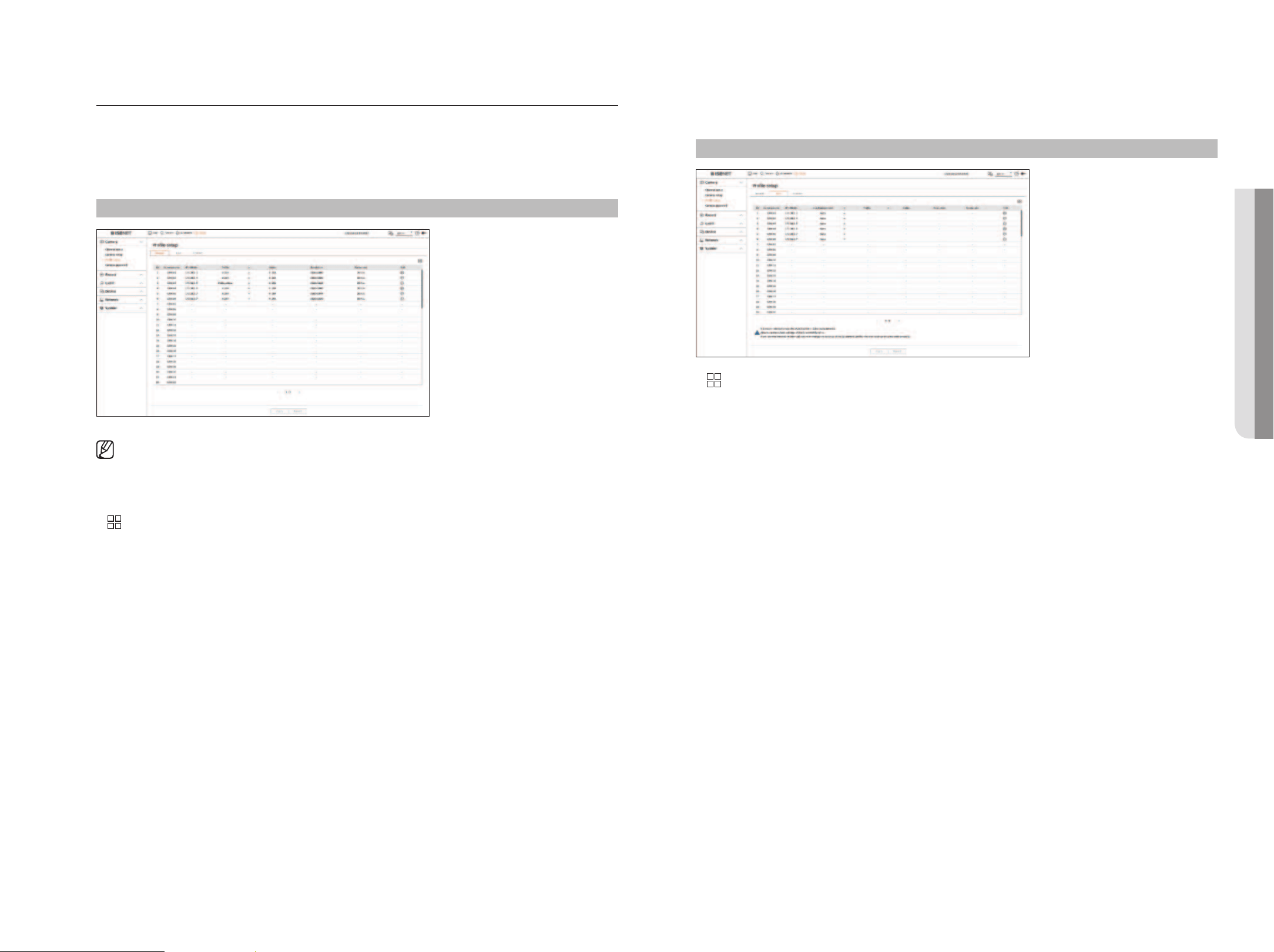
English _51
Setting the Profiles
Setting the Recording Profile
You can configure the video profile settings for instructing the network camera (connected to each channel) to
make recording.
Setup > Camera > Profile setup > Record
■
You can configure the settings only for the profiles that are supported by the camera.
■
If the profiles used for recording and network are different, camera's video feed may not comply with the frame rate as specified in the
camera.
■
It is recommended to set the identical codec for the Record/Live/Remote profile when setting the camera profile.
●
: Displays the camera of the corresponding channel as a list or a thumbnail.
●
Camera name : Display the camera name.
●
IP address : Display the IP address of a camera.
●
Profile : You can select the recording profile for selected channel.
●
Codec : You can check the codec for selected channel.
●
Resolution : You can select the resolution for selected channel.
●
Frame rate : You can set the frame rate for selected recording profile.
●
Edit : You can add, change, and delete the camera profiles.
Setting the Live Profile
You can change the live transfer settings of the network camera.
Setup > Camera > Profile setup > Live
●
: Displays the camera of the corresponding channel as a list or a thumbnail.
●
Camera name : Display the camera name.
●
IP address : Display the IP address of a camera.
●
Live replacement : You can select the live profile setup mode.
If you select <Manual> the profile setup items are enabled, and you can change settings manually.
– Auto : For the profile for live monitoring, a profile optimized for each split mode is displayed, along with the
‘Live4NVR' profile automatically generated at the time of the camera registration.
– Manual : Live monitoring is performed with the profile selected by the user from the registered camera
profiles.
– Record : Live monitoring is performed with the profile set for recording.
●
Profile : You can set the camera profile.
●
Codec : Show the codec of the selected profile.
●
Resolution : Show the resolution of the selected profile.
●
Frame rate : Show the frame rate of the selected profile.
●
Edit : You can add, change, and delete the camera profiles.
• SETUP
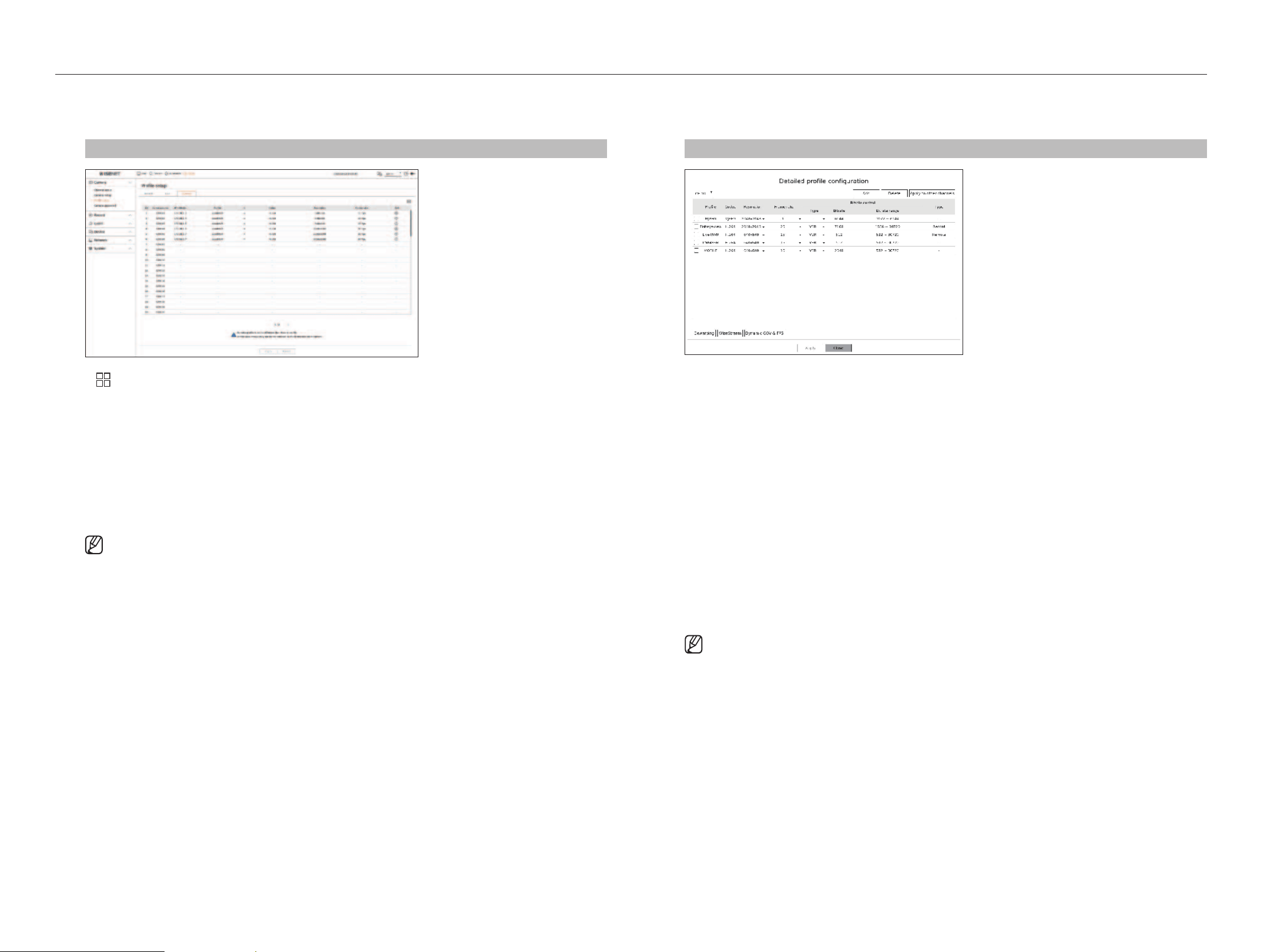
52_ setup
setup
Setting the Remote Profile
You can set the video profile transmitted to the network.
Setup > Camera >
Profile setup > Remote
●
: Displays the camera of the corresponding channel as a list or a thumbnail.
●
Camera name : Display the camera name.
●
IP address : Display the IP address of a camera.
●
Profile : Select a network profile for the connected camera.
●
Codec : Show the codec information for the selected network profile.
●
Resolution : Display the resolution for the selected network profile.
●
Frame rate : Shows the selected network profile's frame rates.
●
Edit : You can add, change, and delete the camera profiles.
■
If the profiles used for network and recording are different, camera's video feed may not comply with the frame rate as specified in the
camera.
Editing the Profiles
You can change the video settings of a registered network camera for each channel.
Setup > Camera > Profile setup
●
Channel selection : You can select camera channels to change their video transmission settings.
●
Add : You can add camera profile. Click on the <Add> button to launch the addition window.
Enter the information and click on the <OK> button to add it to the list.
●
Delete : You can delete the selected profile from the list.
●
Apply to other channels : If you select <Apply to other channels>, “Apply to other channels” confirmation
window will appear.
After selecting channels that the settings will be applied to, click on <OK> to apply them to the selected
channels.
●
Profile : You can check the video profile of the camera connected in the camera setup.
●
Codec : You can check the codec for the selected channel.
●
Resolution : You can change the resolution of the selected channel.
●
Frame rate : You can change the frame rate of the selected channel.
●
Bitrate control : You can change the bitrate of the selected channel.
●
Type : Displays the currently applied profile.
■
If you change specific profile settings for each product, the frame rate's setup range may be changed.
Example) If you set the frame rate for the first profile to 30 fps, then the setting range for the second profile may be changed to 15 fps.
■
Any settings other than codec, resolution, and frame rates can be changed in the setup menu of the camera web viewer. For camera web
viewer, refer to the "Setup Viewer > Setting the Camera > Camera Setup" page in the Table of Contents. Click <Camera webviewer>
button for connection.
■
If you change the current profile settings, you may encounter an interrupted playback on the recording or live screen for a certain time.
■
Changes made in your camera’s setup page will be applied immediately. But any changes made through the camera's online website, it
may take up to 3 minutes to apply the changes.
■
Bitrate settings are not supported for ONVIF cameras.
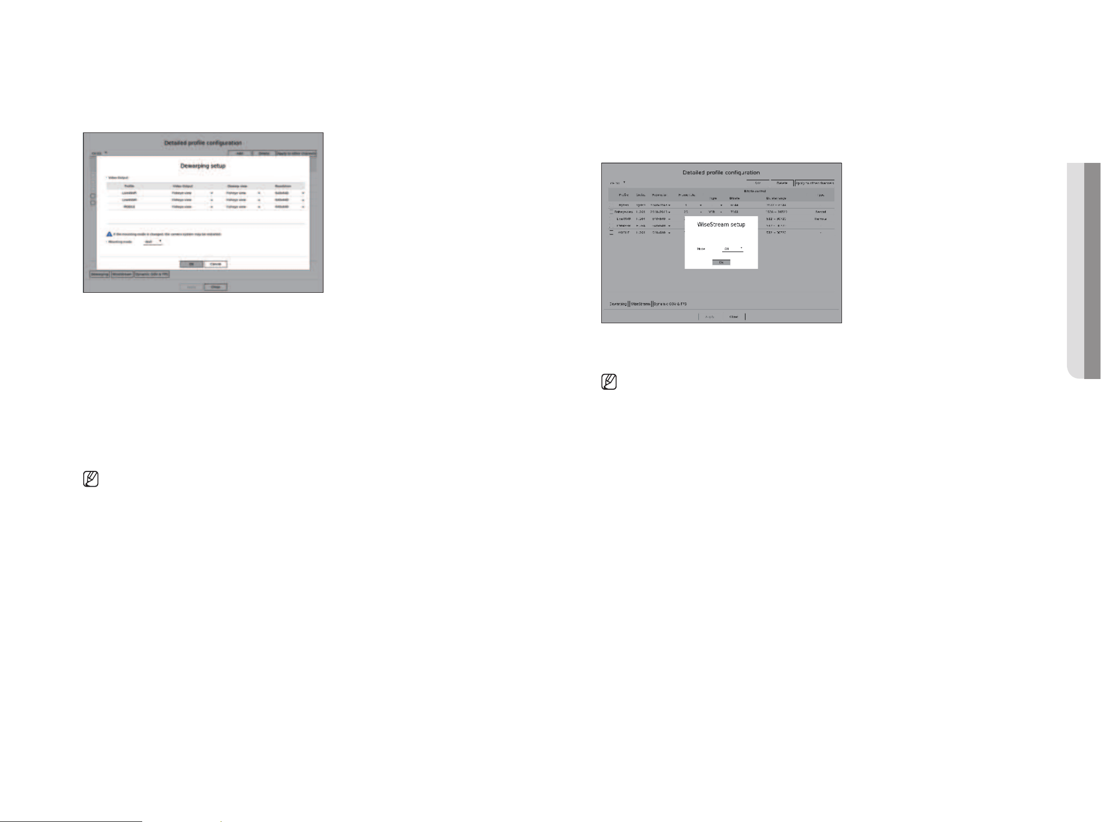
English _53
Dewarping Setup
Press the <Dewarping> button at the bottom of the <Detailed profile configuration> window to go to the
distortion correction setup popup window for each channel.
●
Profile : Displays the profile type.
●
Video output / Dewarp view: You can set <Video output> and <Dewarp view> for each profile type.
– Fisheye view : If you select <Fisheye view> from <Video output>, the <Fisheye view> is automatically
selected for <Dewarp view>.
– Dewarp view : If you select <Dewarp view> from <Video output>, you can set <Quad view>,
<Panorama>, or <Quad view 1 - 4> for <Dewarp view>.
■
You can select view modes supported by your camera.
●
Resolution : You can set the resolution of the profile.
●
Mounting mode : You can change the fisheye installation type. You can select a view mode from among
ceiling/ground/wall depending on the installation location.
■
If there is no camera registered in the Recorder that supports fisheye view, Dewarping Setup will not be available.
How to set WiseStream
Function to analyze the complexity of the video and effectively reduce the data size while maintaining the
quality. For details, refer to the camera's help or the product's user guide.
Press the <WiseStream> button at the bottom of the <Detailed profile configuration> screen to go to the
WiseStream setup popup window for the channel.
●
Mode : You can choose the degree of video compression. You can choose <Off>, <Low>, <Medium>, or
<High>.
■
WiseStream setup cannot be executed if there is no camera registered in Recorder that supports WiseStream.
• SETUP
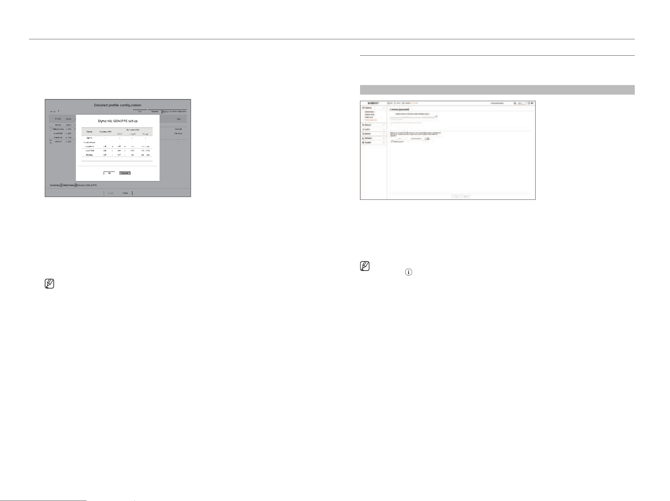
54_ setup
setup
Setting Camera Password
You can change the passwords of all registered cameras at once.
You can register the camera’s ID and password.
Setup > Camera > Camera password
●
Password : Enter the new password for the factory default camera according to the password setting rules.
The initial password for the camera must be entered.
●
Confirm password : Input the new password again.
●
ID : Enter the ID of the camera whose ID and password are set.
●
Password : Enter the password of the camera whose ID and password are set.
■
When the password is in factory reset, it can be changed and managed in a batch.
■
If you click < >, a basic guide for password setup is displayed.
■
If you select <Show password>, the current password is displayed as the actual input characters.
■
If you check the <Change the password of all registered cameras>, the passwords of all cameras are changed with the entered
password.
■
Up to 3 sets of camera ID with password and password can be registered.
You can use the registered camera ID/PW to automatically discover and register the camera from the "Channel setup > Auto detect"
screen.
■
A camera password registered with ONVIF and RTSP cannot be changed.
Dynamic GOV/FPS setup
Dynamic GOV can be used to automatically change the length of GOV depending on the video condition. For
details, refer to the camera's help or the product's user guide.
At the bottom of the <Detailed profile configuration> screen, press the <Dynamic GOV & FPS> button to
open the dynamic GOV/FPS setup popup for the channel.
●
Profile : Shows the video profile of the connected camera setting.
●
Dynamic FPS : Automatically adjusts the frame rate (frames per second) based on the video conditions.
●
Dynamic GOV
– Mode : Set the GOV length to change automatically.
– Length : Enter the maximum GOV length value to be applied when there is no motion in the video.
Minimum GOV value can be set on the camera web page.
– Range : The range of the input value of <Length> is displayed.
■
Any profile not supported with the dynamic GOV/FPS setting is marked with '-'.
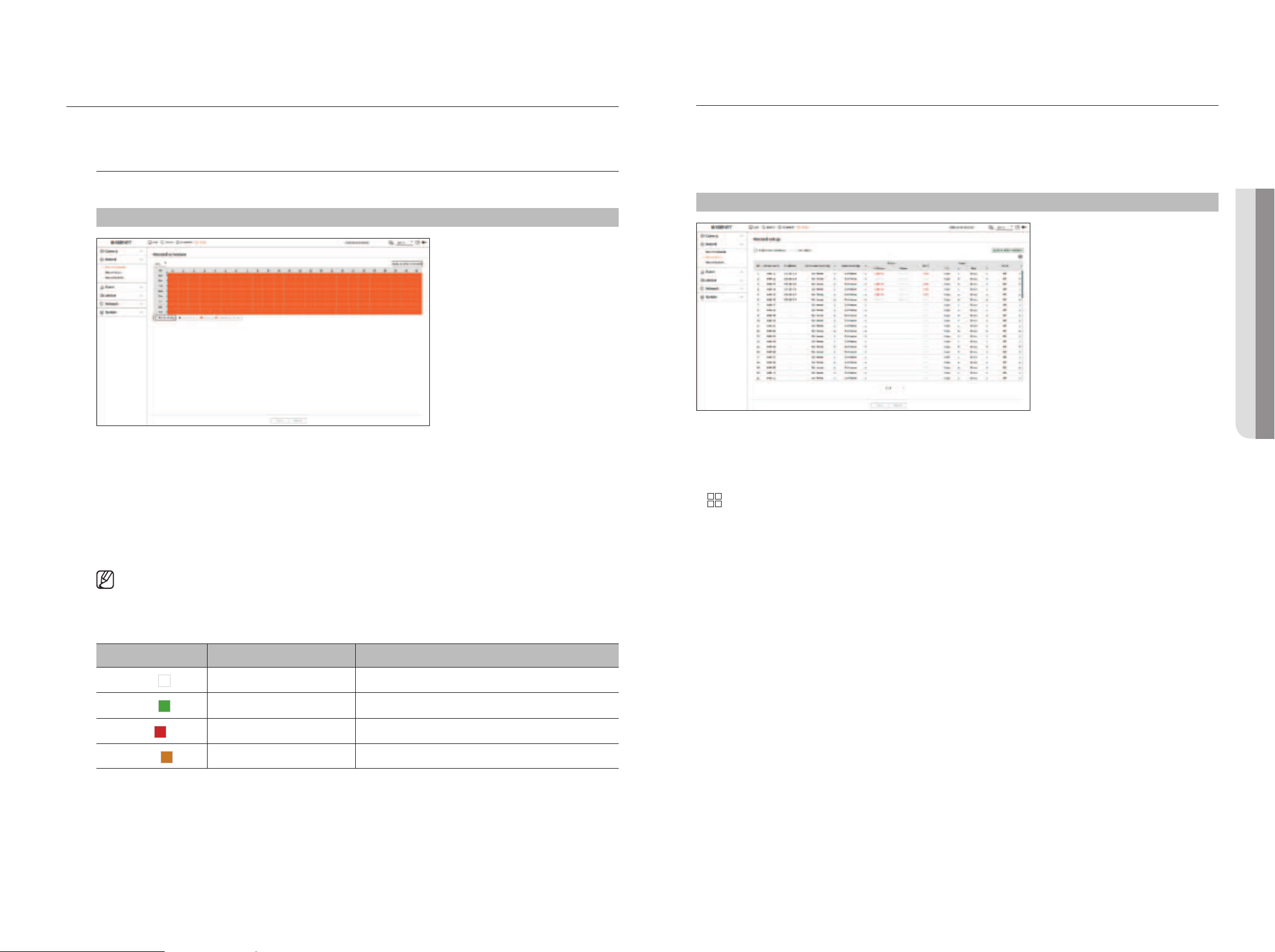
English _55
SETTING THE RECORDING
You can setup scheduled recording, event recording and other recording related settings.
Record Schedule
If you set a recording schedule for a specific date and time, the recording will start at that specific time.
Setup > Record > Record schedule
●
Channel : Select the channel you want to set.
●
All : The entire time range (Monday through Sunday including holidays, AM 0~ PM 23) will be reserved with the
same recording schedule.
●
Apply to other channels : If you select <Apply to other channels>, “Apply to other channels” confirmation
window will appear.
After selecting channels that the settings will be applied to, click on <OK> to apply them to the selected
channels.
■
Event recording and scheduled recording starts about 3 seconds prior to the event/schedule for guaranteed recording.
Record setting by the color
Color Function Description
White (
)
No recording No schedule / event recording
Green (
)
Continuous Scheduled recording only
Red (
)
Event Event recording only
Orange (
)
Continuous/Event Both scheduled / event recordings
●
Each press of a selected cell will cycle through <No recording>-<Continuous>-<Event>-<Continuous/
Event>.
Record Setup
You can set the resolution and number of recordings for each channel when an event occurs or during a normal
recording.
You can check frame rates and data transfer amount of Full Frame and Key Frame recordings for each channel,
and set the transfer limit for recordings.
Setup > Record > Record setup
●
Apply to other channels : If you select <Apply to other channels>, “Apply to other channels” confirmation
window will appear.
After selecting channels that the settings will be applied to, click on < OK> to apply them to the selected
channels.
●
: Displays the camera of the corresponding channel as a list or a thumbnail.
●
Camera name : Display the camera name.
●
IP address : Display the IP address of a camera.
●
Continuous recording / Event recording : Set the recording method for Continuous recording or Event
recording.
– Full frame : Records all frames fed by the camera.
– I-frame : Records only key frames fed by the camera. It depends on the camera's settings.
– Off : No recording is made.
●
Frame
– Full frame : Shows the amount of data for all the scene recordings.
– I-frame : Shows the amount of data for the main scene recordings.
●
Limit : Set the amount of data allowed for input for each channel.
●
Event : When an event occurs, you can set which point you will start or stop recording.
– Pre : When an event occurs, recording will be started regardless of the time set.
If you set it to five seconds, recording will start at five seconds before an event occurs.
– Post : When an event occurs, recording will continue after the time set.
If you set it to five seconds, recording will continue for a further five seconds after an event is finished.
●
Audio : Specify whether to record the sound received from the camera or not.
• SETUP
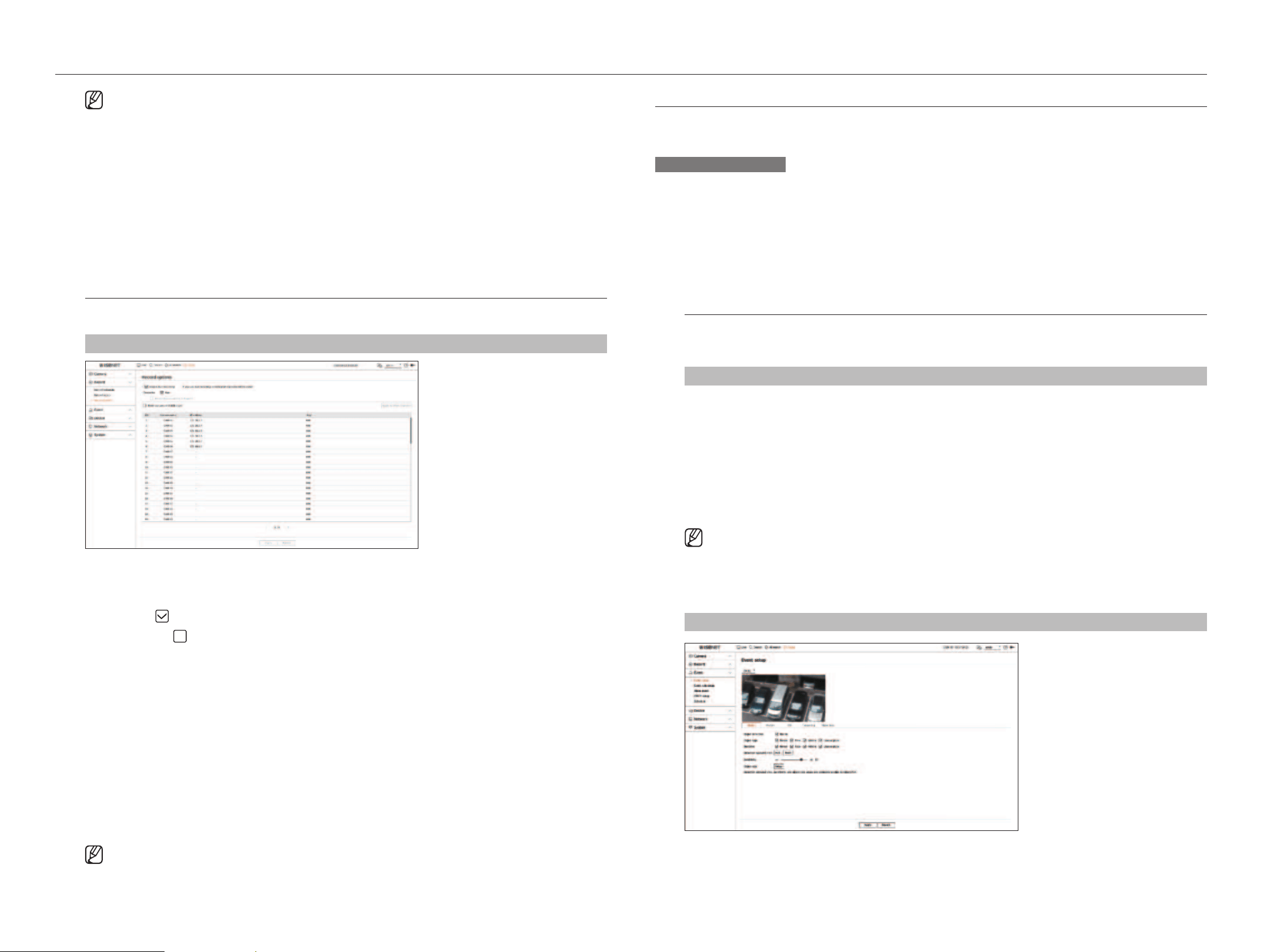
56_ setup
setup
■
If a channel's data transfer exceeds defined allowed limit, then it may affect to other channels, and may force switching to <I-frame>
recording even when the channel is configured to <Full frame> recording mode. For Key Frame recording channels, the icon for limited
recording appears on the live screen's top side.
But if the sum of the limits is below the max limit, you can still receive the entire frames despite exceeding the permitted bitrates for each
channel.
■
A channel displayed in yellow indicates that the recorded data is not being transferred from the camera and that the recording is being
performed temporarily using another profile on the camera.
Check the channel information to see the applied profile to the channel listed in yellow.
A channel displayed in orange indicates that the amount of inputted data is greater than the permitted data amount. In this case, it is
impossible to record all of the incoming frames. Instead, only part of the frames (1 or 2 frames per second) can be recorded.
To resolve this issue, you must set the permitted data amount to be greater than the amount of inputted data.
Refer to the "Live > Live screen mode > Check the camera status" page in the Table of Contents.
Record Options
You can set recording options, such as enabling dual recording or overwrite of hard disk for repeated recording.
Setup > Record > Record options
●
Enable dual recording : Select this if you want to record both the recording profile and remote profile at the
same time. Enabling dual recording is applied with a profile suitable for split mode during playback.
●
Overwrite : Select the recording method when the hard disk storage capacity is full.
– Checked (
) : If the HDD is full, this will overwrite the existing data and keep recording.
– Not checked (
) : If the HDD is full, this will stop recording automatically.
●
Beeps when recording is stopped: If <Overwrite> has not been set, this button is enabled. Specifies whether
to use beep or not when HDD recording ends.
If you check it, the beep will sound on the disk full and the recording stops.
●
Retention period : If you check this option, the period list box is active, and you can set the automatic deletion
period. Specify the deletion period to delete any earlier data than the specified date. However, you can search
for data from the current time to the selected date.
■
If <Overwrite> has been set, this button is enabled.
■
You can select a channel and set a different recording duration for each channel.
●
Apply to other channels : If you select <Apply to other channels>, “Apply to other channels” confirmation
window will appear. After selecting channels that the settings will be applied to, click on <OK> to apply them
to the selected channels.
■
If you press <Retention period> when you have completed your settings, all the existing data earlier than the specified period will be
deleted automatically. If you need to keep your old data, export it first.
SETTING THE EVENT
You can set the event-related settings such as whether or not an event is detected for each channel and whether an
alarm occurs.
AI function setup guide
To use AI function, set any of the following options as necessary : See the relevant page for detailed setup method.
– Setup > Event > Event setup > Object
– Setup > Event > Event setup > Mask
– Setup > Event > Event setup > IVA
– Setup > Event > Event rule setup
Event Setup
You can configure whether or not to detect events sent by the camera for each channel and configure detailed
settings.
Setup > Event > Event setup
●
Object : You can set detailed settings for object detection of the connected camera.
●
Mask : Sets detailed settings for mask detection of the connected camera.
●
Motion : You can set detailed motion detection for the connected camera.
●
IVA : You can set up intelligent video analytics of the connected camera.
●
Tampering : You can make detailed settings for tampering detection, such as when the screen of a connected
camera is obscured or the camera location is changed.
●
Video loss : You can configure the detailed settings for video loss detection on the connected camera.
■
The settings for Object detection may vary depending on the recorder model or the connection of Wisenet AI camera.
Object
Setup > Event > Event setup > Object
●
Object detection : You can set whether to enable object detection.
●
Object type : You can select the object type to detect.
■
Object items may vary depending on the camera model.
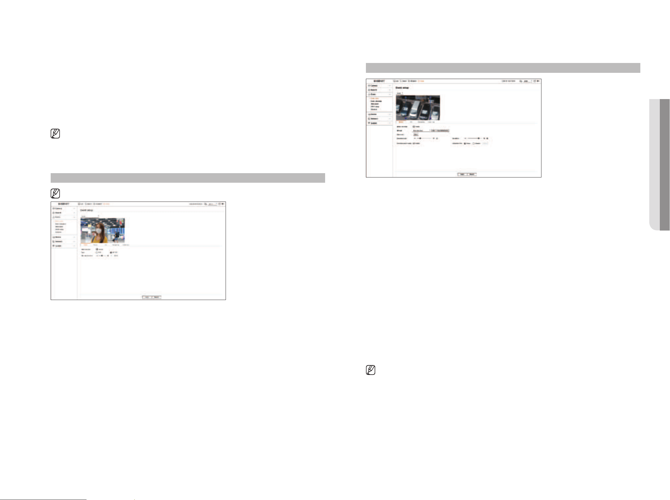
English _57
●
BestShot : You can set the object to display the bestshot items.
■
Set the same as the item selected in <Object type> to display the best shot when an event is detected.
●
Detection excluded area : You can set the exclusion area for AI object detection. Click <Add> to set the
detection exclusion area on the preview screen.
●
Sensitivity : Sets the object detection sensitivity.
■
Setting the sensitivity level high increases the object detection rate but also raises the detection error rate.
●
Object size : You can set the size of the object to recognize the motion.
– Click <Setup> to select the minimum/maximum size and set the object size on the preview screen.
■
If detection errors occur frequently, set the detection excluded area or lower the object detection sensitivity.
Mask
Setup > Event > Event setup > Mask
■
The settings for Mask detection may vary depending on the recorder model or the connection of Wisenet AI camera.
●
Mask detection : Sets whether or not to use mask detection.
●
Type : You can select the mask detection type.
●
Minimum duration : Sets the minimum observation duration upon mask detection.
Motion
Setup > Event > Event setup > Motion
●
Motion detection : You can set whether to enable motion detection.
●
MD type : You can set a detection area and a detection excluded area.
– Detection area : Set the area to detect motion.
– Detection excluded area : Set the area to not detect motion.
– Add : After selecting the desired area item, set the area on the preview screen.
– Area initialization : You can clear all the set areas.
●
Object size : You can set the size of the object to recognize the motion.
– Click <Setup> to select the minimum/maximum size and set the object size on the preview screen.
●
Detection level : You can set the basic level required for motion detection. Level values can be set for each
detection area set in <MD type>. If a motion value is bigger than the set level, then a motion detection event
is triggered.
●
Detection result display : You can overlay the detection area over video.
●
Sensitivity : You can set the sensitivity of motion detection for each area. Set a lower sensitivity for an
environment where the background and an object are clearly distinguishable and a higher sensitivity for an
environment where the background and an object are not clearly distinguishable.
●
Activation time : You can set the activation time for motion detection.
– Always : Detects motion regardless of time.
– Schedule : Detect motion only during the set period. Click <Setup> to set the detection schedule.
■
Each camera product support different features. For more information, see the camera manual or help.
• SETUP
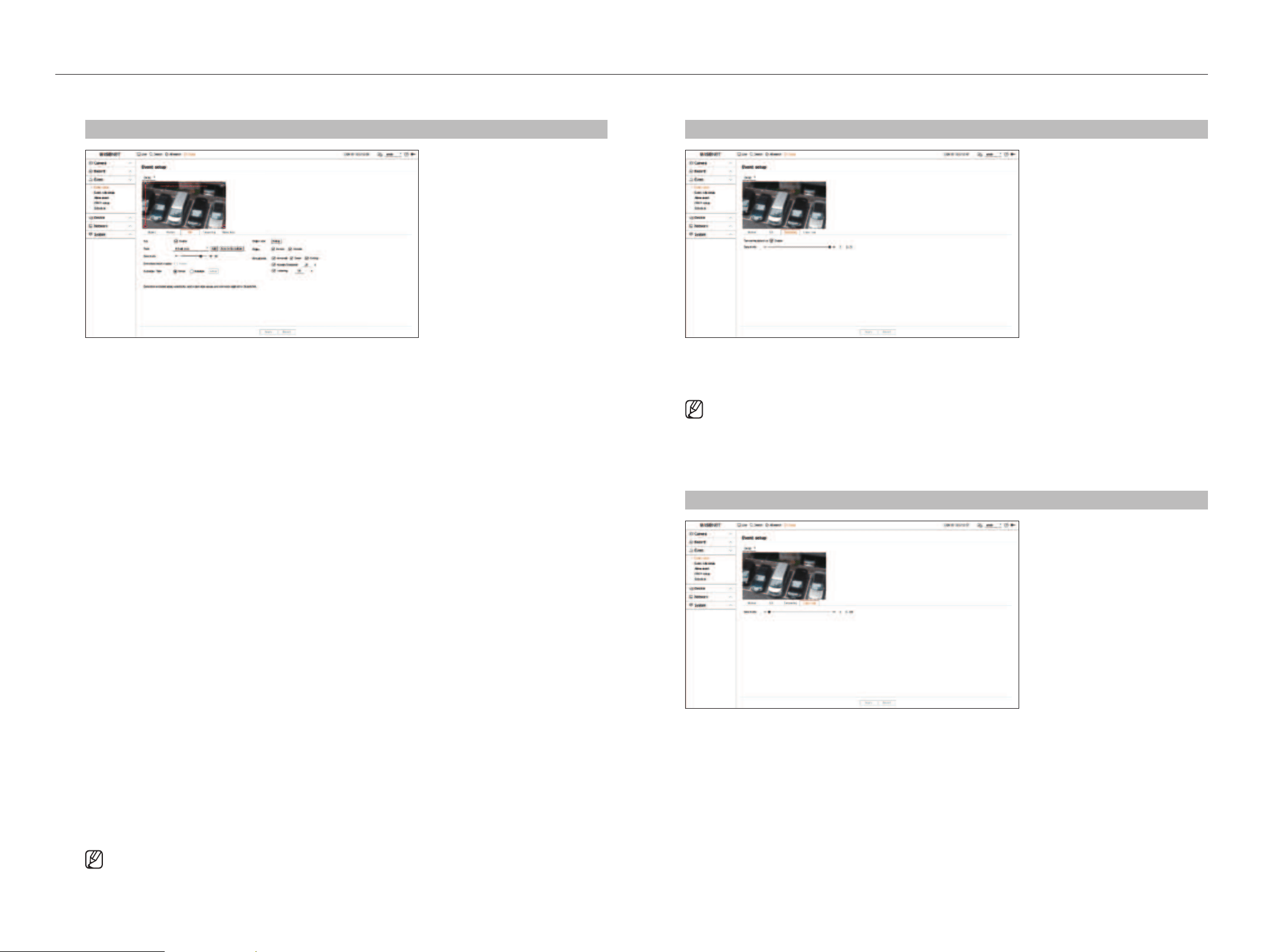
58_ setup
setup
Tampering
Setup > Event > Event setup > Tampering
●
Tampering detection : You can set whether to enable tampering detection.
●
Sensitivity : Sets the tampering detection sensitivity.
■
Since tampering detection is designed for optimal performance based on the sensitivity level by the user, there may be no noticeable
change in the tampering detection performance depending on the sensitivity level under normal monitoring conditions.
Video loss
Setup > Event > Event setup > Video loss
●
Sensitivity : You can set the video loss detection sensitivity. Depending on the sensitivity level (5 second
intervals), you can delay the occurrence of an event from 15 seconds (level 1) up to 60 seconds (level 10) later.
IVA
Setup > Event > Event setup > IVA
●
IVA : You can set whether to enable intelligent video analytics.
●
Type : You can set a virtual line, virtual area, and detection excluded area.
– Virtual line : Set the virtual line to enable intelligent video analytics.
– Virtual area : Set the area to enable intelligent video analytics. You can set the details of virtual areas to fit
your purposes.
■
Intrusion : Creates an event when the motion of an object in the designated area is detected.
■
Enter : Creates an event when a moving object enters into the target area from the outside.
■
Exiting : Creates an event when a moving object goes out of the target area.
■
Appear/Disappear : When an object which does not exist inside the area designated by the user appears inside the area without passing the
area line and remains for a certain period of time, or if an object which exists inside the area disappears, an event is created. You can enter the
duration to be recognized as an event.
■
Loitering : Creates an event when the motion of a loitering object in the virtual area is detected. You can enter the duration to be recognized as
an event.
– Detection excluded area : Set the area to not enable video analytics in the virtual line and the virtual area.
– Add : After selecting the desired area item, set the area on the preview screen.
– Area initialization : You can clear all the set areas.
●
Sensitivity : You can set the motion detection sensitivity for the virtual line and the virtual area.
●
Detection result display : You can overlay the detection area over video.
●
Activation time : You can set the activation time to recognize motion analysis.
– Always : Detects motion analysis regardless of time.
– Schedule : Detects motion analysis only during the set period. Click <Setup> to set the detection schedule.
●
Object size : You can set the size of the object to recognize the motion.
– Click <Setup> to select the minimum/maximum size and set the object size on the preview screen.
●
Object : You can set the object to enable video analytics.
■
Objects are visible only when an AI camera is connected.
■
Object details may vary depending on the recorder model.
■
Each camera product support different features. For more information, see the camera manual or help.
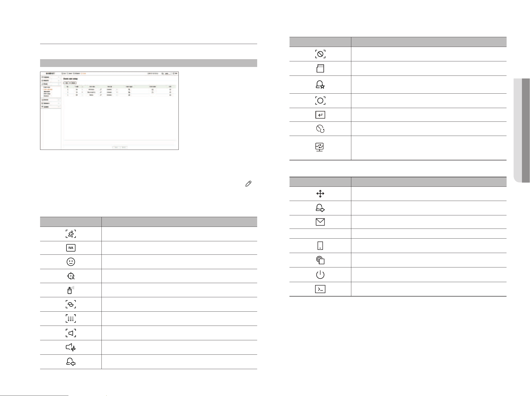
English _59
Event Rule Setup
You can set the event trigger and action rule to output an alarm when an event occurs.
Setup > Event > Event rule setup
●
Add : Adds a new event rule by selecting from rule creation or rule copy.
●
Delete : Deletes the selected event rule.
●
Enable : Specify whether to enable the corresponding event rule.
●
Rule name : Displays the name of the event rule. You can change the name of the event rule by clicking < >.
●
Schedule : Displays the schedule set in the event rule.
●
Event trigger : Displays the event trigger set in the event rule.
■
The event trigger will be displayed in the live video window when an event is received, and will be saved as an event log record.
Item Description
Motion detection
IVA
Face detection
Auto tracking
Tampering detection
Defocusing detection
Fog detection
Audio detection
Sound classification
Alarm input (camera), Alarm input (Recorder)
Item Description
Video loss detection
SD Card
Dynamic event
Example) DigitalAutoTracking, Queue, ShockDetection, MaskDetection
ObjectDetection
Manual trigger
Video loss recovered
System event
(Change password, Upgrage, HDD state, Power On/Off, Start manual recording, End manual recording,
Recording error, Account locked)
●
Event action : Displays the event action set in the event rule.
Item Description
Record/Go to preset
Alarm output
E-mail
FTP Transfer images to FTP server
Mobile push notification
Monitor event
Shutdown
User coding
●
Edit : Changes the registered event rule.
• SETUP
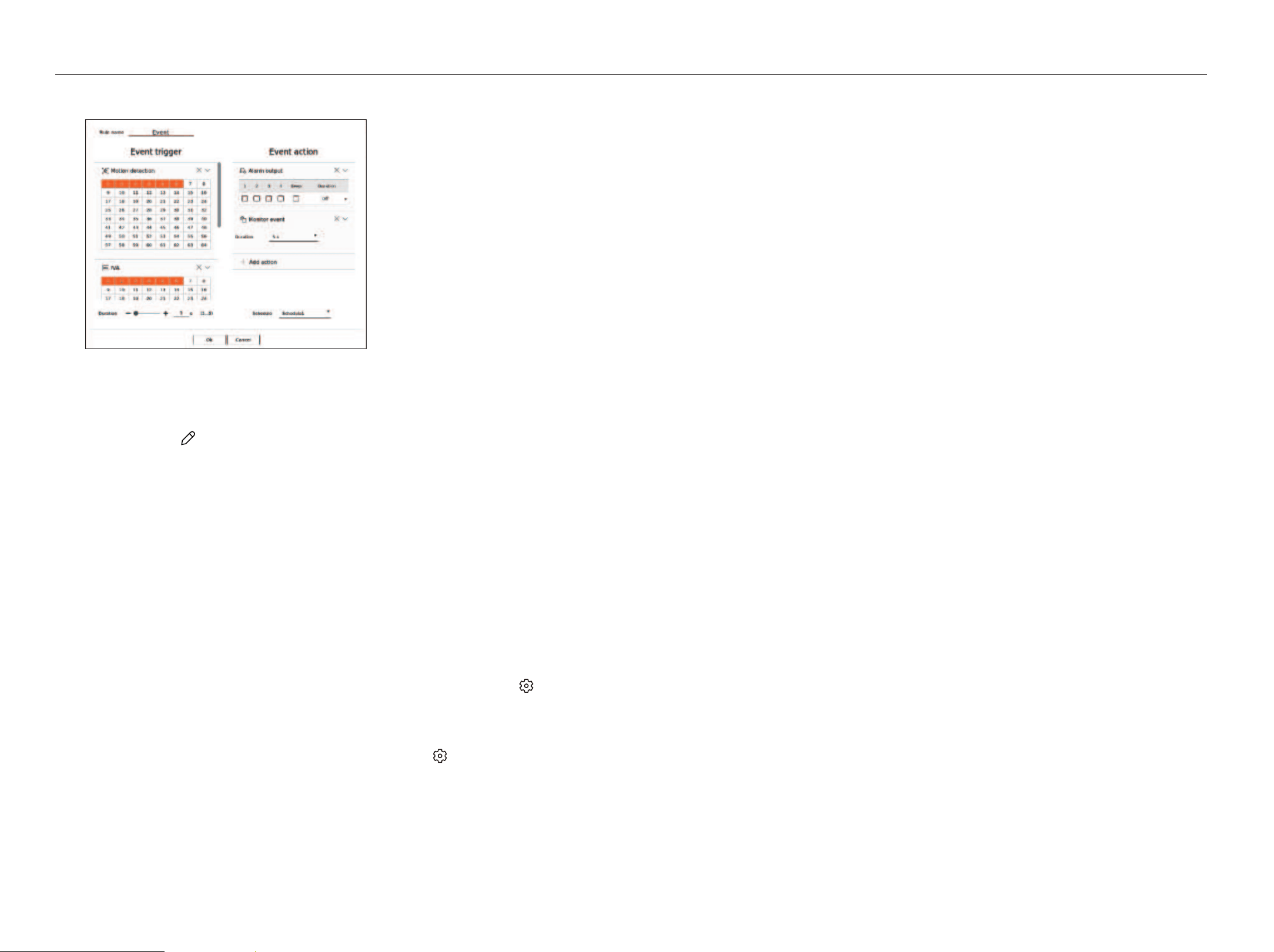
60_ setup
setup
Register a new event rule
1. Click <Add> in the <Event rule setup> field.
2. Click <Create rule>.
●
Copy rule : When you select one of the event rules already created, it is added to the events list.
You can click <
> to modify the rule name.
3. Set the details when the event rule setting window is displayed.
●
Rule name : Enter the name of the event rule.
●
Event trigger : Click <+ Add trigger> to set the event trigger and channel.
■
Up to three event triggers can be added.
■
The event trigger option may vary depending on the recorder model.
■
Duration is the waiting time to recognize the occurrence of a selected event. You have to select two or more event triggers to set this option.
The event action will run only when all the selected event triggers occur within the duration time.
■
Event triggers will be displayed on the live screen when an event occurs and are used for event log recording.
■
To select a channel to detect an event trigger, click or drag the desired channel in the channel table. It will be displayed in orange when a
channel is selected.
●
Schedule : Select the schedule to run the event action.
●
Event action : Click <+ Add action> to set the event action.
– Record/Go to preset : Set the PTZ preset to be displayed when an event occurs. Click <
> to set camera
presets for each channel.
– Alarm output : Set the alarm out to be generated when an event occurs. Select the output terminal
according to the number of alarm terminals on the recorder to set the alarm duration.
– E-mail : Set up users to receive e-mail when an event occurs. Click <
> to select users to receive the
e-mail.
■
Set the interval for sending events in the “Setup > Network > E-mail > Events" menu.
– FTP: When an event occurs, the images are transferred to the designated FTP server. The overlapping
events that occurred during the set delivery interval will be sent as text in an html format file.
■
Set the FTP connection and delivery interval in the “Setup > Network > FTP" menu.
– Mobile push notification : When an event occurs, the event push notification will be displayed on the
connected smart phone.
– Monitor event : When an event occurs, the screen of the corresponding channel will be displayed by
switching to the live screen. When selecting event monitoring, set the alarm duration in consideration of
network conditions.
– Shutdown: When an event occurs, a pop-up window will appear. You can select <Shutdown> or
<Cancel>.
– User coding: It can be selected when <Manual trigger> is set. You can set the WISENET camera to
execute the SUNAPI command entered in <User coding> when an event occurs. Click <Test> to test the
execution of the entered SUNAPI command.
■
Event action will run only when all set event triggers occur. If only one of the multiple events set has occurred, the event action will not run.
■
Set the event action only when necessary.
4. Click <OK> at the bottom of the setting window to register the event rule.
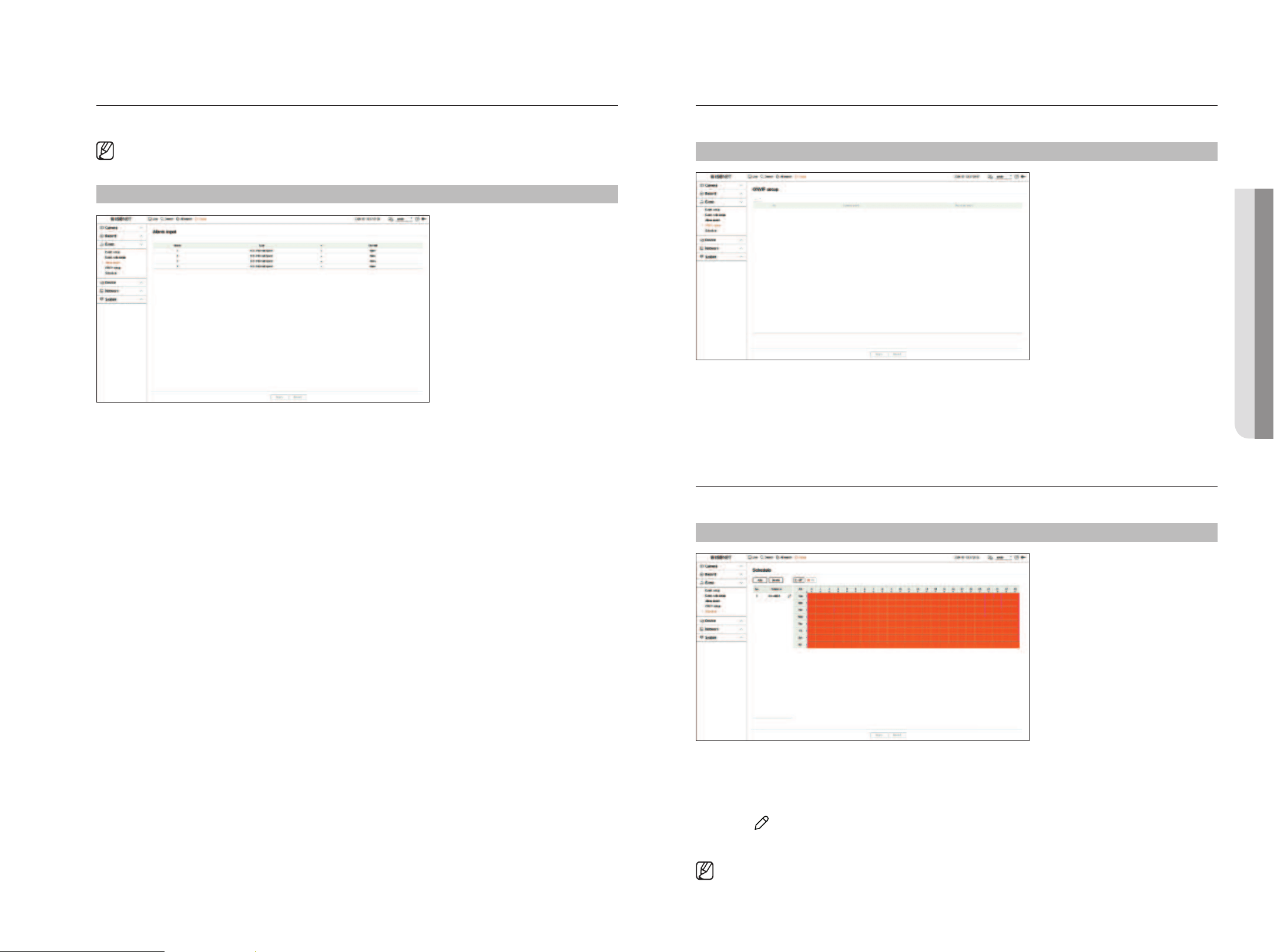
English _61
ONVIF Setup
You can set the details related to camera events registered with the ONVIF protocol.
Setup > Event > ONVIF setup
●
No. : Select the channel to which the ONVIF camera is registered.
●
Camera event : It shows the list of all the events supported by a camera by using the ONVIF protocol.
●
Recorder event : You can map the list of events supported by a camera to events that the Recorder can detect.
There is no default value. It only shows the value sent by a camera.
Schedule
When setting the event rule, you can set the operating time of the event action.
Setup > Event > Schedule
●
Add : Add a schedule by setting the desired day and time.
– Off : Displayed in white and no alarm will be output even if an event occurs.
– On : Displayed in orange and an alarm will be output only when an event occurs.
■
Click < > to change the schedule name.
●
Delete : Delete the selected schedule.
■
You cannot delete the schedule in use.
Alarm Input
You can set the operation of the alarm sensor.
■
This function is not supported in some models.
Setup > Event > Alarm input
●
Type : Set the mode in which the alarm sensor will operate.
– Off : Alarm sensor is disabled. Alarm is not used.
– N.O. (Normal Open) : Sensor is opened. If the sensor is closed, it generates alarm.
– N.C. (Normal Close) : Sensor is closed. If the sensor is opened, it generates alarm.
●
Channel : You can set the channel to execute an event action when a signal is input to the selected alarm.
This is possible when <
Alarm input (Recorder)> trigger and event action are set up in the "Event > Event rule
setup" menu.
• SETUP
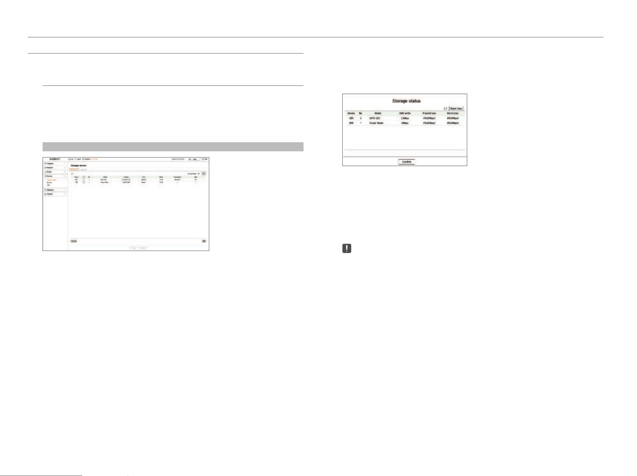
62_ setup
setup
SETTING THE DEVICE
You can make the detailed settings for devices such as storage device and monitors.
Storage Device
You can set the storage device usage and check the setting status.
Checking and formatting the device
You can check storage devices and their capacity, usage as well as status.
The connectable storage devices are HDD and USB.
Setup > Device> Storage device > Management
●
Device : Displays the storage device type.
●
No. : You can check the designated number for the built-in HDD.
●
Model : Displays the model name of the storage device.
●
Capacity : Displays the amount of storage device use and the full capacity.
●
Type : Displays the usage type of the storage device.
●
Status : Displays the current working condition of a storage device.
■
If the Status is set to <Not Defined>, format the storage device before use.
●
Temperature : You can check the temperature of the HDD mounted in the Recorder.
●
Time : Displays the use time of an HDD.
●
Format : Select a storage device and click on format after which a format confirmation window appears.
Click on the <OK> button to format the selected storage device.
●
Storage Status : Displays the working status of a storage device. Click the <View> to display the storage status
window.
– Red : Displays the situation of video loss.
– Green : Displays the normal situation without video recording losses.
– View : Click <View> to see detailed information.
■
HDD write : Displays the current rate of recording.
■
Present loss : Displays the current recording loss rate.
■
Worst loss : Displays the maximum amount of losses up until now.
■
If loss is continuously generated, check the following.
For more information, refer to the "Troubleshooting (FAQ)” in the Appendix.
– When data is lost due to system failure (reset the rate of data transferred from the camera)
– When there is a problem in HDD recording performance due to an HDD malfunction (check the HDD error or replace the HDD)
■
Formatting will delete all the recording data that has been saved. Be careful.
■
While formatting is ongoing, you cannot record video.
■
Do not remove a formatting device until it is finished.
■
After installing an HDD, if the state of use of the HDD is <Not Defined>, format the HDD before use. (If the warning message persists after
formatting, replace the HDD with a new one)
●
ARB : Video that was not recorded due to a camera disconnection can be backed up after the connection with
the camera is re-established. Press the button and an <Auto recovery backup (ARB)> window is opened.
– Select HDD : Select a HDD to be set to ARB.
– Capacity : Shows the capacity of the HDD to be set as ARB.
– Select channel : Select a channel to run the ARB.
■
You can select multiple channels. If you select <All channels>, all channels will be selected.
– ARB bandwidth : Select a bandwidth for the ARB function.
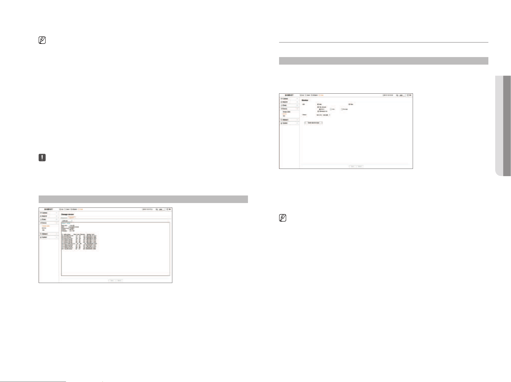
English _63
Monitor
You can set the information displayed on the monitor as well as the output system.
Setup > Device > Monitor
Monitor settings
You can set the monitor output related screen displays, switching time, video display, etc.
●
OSD : Only checked items among date, time, channel name and information icon will be displayed on the
monitor screen.
– You can adjust the size of the channel name displayed on the live screen. Select from among <Default>,
<Large>, <Very large>.
●
Monitor : Set the video display resolution.
■
If the newly selected resolution does not fit with the monitor, the display won’t function properly. In this case, wait until the native
resolution is restored and then switch to another resolution of your choice.
■
The ARB feature is available only when your video is saved in the SD card after registering your Wisenet camera using the Wisenet protocol.
This is only supported in SUNAPI 2.3.2 or later.
■
Set the profile bitrate used for recording a video in the SD card of camera to 6144 kbps or below.
For more information on how to set the SD card recording profile, see your camera manual.
■
Enable the ARB function when installing the recorder for the first time. If set during use, part of video may be deleted to secure space for
ARB.
■
To use the ARB function correctly, both the camera and Recorder should be time synchronized with the time server.
Refer to the "Setup > Setting the System > Date/Time/Language" page in the Table of Contents.
■
ARB function is activated when Recorder starts/when the channel camera set is reconnected/when an Recorder recording missing section
recurs at regular intervals after Recorder starts.
■
Recorder recording missing section that can be restored with the ARB function is for 24 hours backwards from the point when the ARB
function is activated.
■
You can check which channels have ARB function activated through the message on each channel screen that is displayed when selecting
a channel.
Refer to the "Live > Live screen mode > Channel Information Display" page in the Table of Contents.
■
For automatically recovered files through ARB, refer to the "Search > ARB Search" page in the Table of Contents.
■
ARB storage capacity is recommended to be at least one day.
Example) If you saved 64 channels with 1 Mbps each, the ARB capacity should be set to 0.7 TB or higher.
■
Do not add or remove an HDD while Recorder is running.
S.M.A.R.T
You can check the connection status and details of the hard disk mounted in the recorder.
Setup > Device> Storage device > S.M.A.R.T
• SETUP
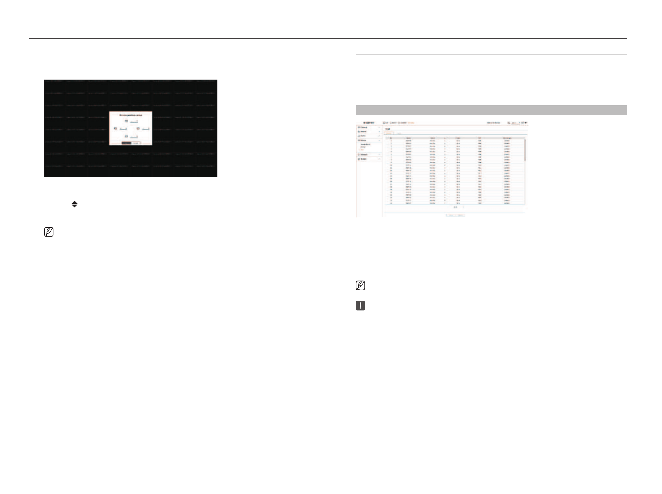
64_ setup
setup
Screen position setup
Some monitors many not display information (camera name, icon) about the Recording, depending on the
condition. Then, you can change the display position of the data.
1. From the monitor setup menu, select <Screen position setup>.
2. Using <
> button to adjust the screen that is cut off.
3. Click <OK>.
■
This product only supports 30Hz at 4K resolution.
Tex t
You can set the POS device setting to send text information and text event information.
Device Settings
You can make detailed settings for the POS device connected to the recorder.
Setup > Device > Text > Device
●
Device : Displays the text device name registered by the user.
●
Enable : Specifies whether to enable text device.
●
Channel : Select a channel to add a device from a channel table.
●
Port : Display a port number that is set.
●
Encoding type : Select an encoding type to use from a list.
■
Epson, Wincor Nixdorf, Axiohom, Radiant System, IBM POS device, and ANPR protocols are supported.
■
POS device connected to Recorder uses TCP/IP communication protocol.
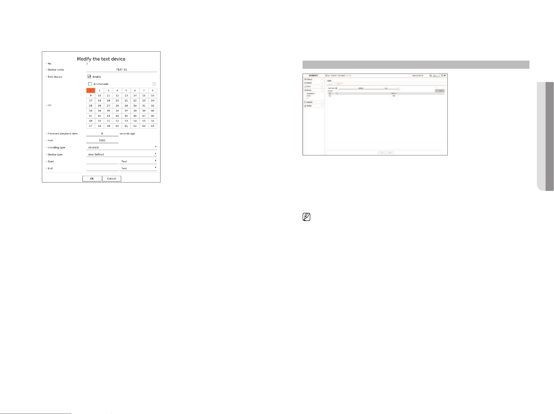
English _65
Registering a Text Device
1. Click the desired item in the text device list.
2. Enter the device information to register in the <Modify the text device> window.
●
Device name : Enter the desired text device name.
●
Text device : Specify whether to enable text device.
●
CH : Select a channel to add a device from a channel table.
●
Pre-event playback time : Enter the start time of the playback from how many seconds before when an event
occurs.
●
Port : Enter the device's port number.
●
Encoding type : Select the encoding type of the device.
●
Device type : Select the device type.
●
Start / End : You can select starting and ending character strings.
– A text string can be entered by using texts, hex codes, and regular expressions.
– Text : Enter a text string to search for.
– Hex Code : Enter a hexadecimal text string to search for.
(Your input should not be in hexadecimal —e.g. 1b40, 1b69)
– Regular expression : Enter a regular expression to search for text strings that follow specific rules.
3. Click <OK>.
Text Event Settings
You can set the text to receive an alarm when an event occurs.
Setup > Device > Text > Event
●
Total amount : Set the condition of the total amount to be notified when a text event occurs. Check whether
the total amount is used, and then select the base amount and range.
●
Keyword : You can register or delete keywords to be notified when an event occurs.
– If the <Add> button is clicked, a screen to add keywords pops up.
– If you select one of the added keywords to delete and click the <Delete> button, the selected keyword will
be deleted.
■
When entering the total amount, set it to 15 characters or less, including minus and decimal point.
■
When entering keywords, set them within 50 characters. Up to 20 keywords can be specified.
• SETUP
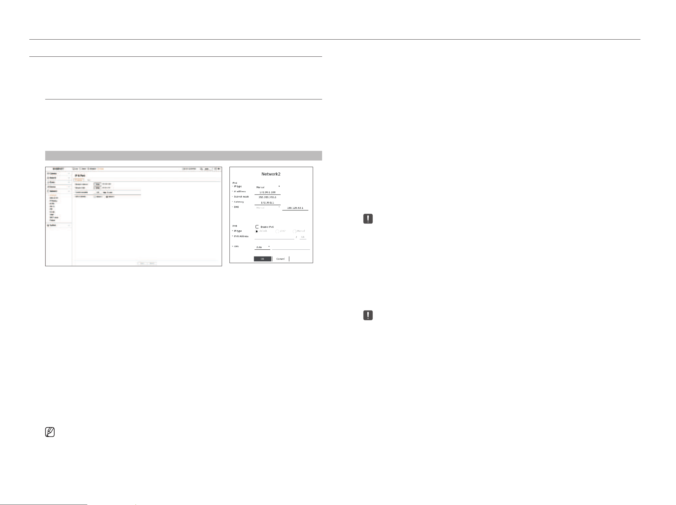
66_ setup
setup
SETTING THE NETWORK
You can set various network functions, such as monitoring live video by connecting to a network from a remote location
and receiving an event by e-mail.
IP & Port
You can set the network connection route and protocol.
Setting a network connection
Sets the protocol and environment of the network.
Setup > Network > IP & Port > IP address
●
Network : Each product supports a different number of network ports. If it supports two or more network
ports, you can set the network for each function as follows.
●
Network 1(Camera) : It can be used as a port for connecting a camera. If you connect a camera, then the
camera video will be transmitted. Using the network information, you can access the web viewer.
●
Network 2 (Viewer) : It can be used as a common port for camera and web viewer connection.
●
Network 3 (iSCSI) : It can be used as a dedicated port for iSCSI connection.
■
Only provided for products that support Network 3.
●
Network (All) : It can be used as a common port for connecting camera, web viewer, and iSCSI.
– IP type : Select the type of network access.
– IP address, Subnet Mask, Gateway, DNS
■
Manual : IP address, subnet mask, gateway, and DNS can be directly entered.
■
DHCP : IP address, subnet mask, gateway, and DNS can be automatically set.
●
Transfer bandwidth : Enter the max data volume of a rate for transfer.
●
Default gateway : Select the default gateway. If there are multiple network ports, set one of them as the default
gateway.
■
The DNS value of DHCP can be directly entered only if you have selected <Manual>.
Connecting and Setting the Network
Networking may differ from the connection method, check your environment before setting the connection
mode.
When no router is used
●
Manual mode
– Internet connection : Static IP, leased line, and LAN environments allows connection between the Recorder
and remote user.
– Network Settings : Set the <IP type> of the connected recorder to <Manual>.
■
Consult your network manager for IP, Gateway and Subnet Mask.
●
DHCP mode
– Internet connection : Connect the Recorder directly to a cable modem, DHCP ADSL modem or FTTH
network.
– Network Settings : Set the <IP type> of the connected recorder to <DHCP>.
When a router is used
■
To avoid IP address conflict with the Recorder's static IP, check followings :
●
Setting the Recorder with a static IP
– Internet connection : Connect the recorder to an IP router where cable modem is connected, or connect the
recorder in the local area network (LAN) environment.
●
Setting the Recorder Network
1. Set the <IP type> of the connected recorder to <Manual>.
2. Check whether the set IP address is in the static IP range provided by the Broadband Router.
IP Address, Gateway, and Subnet Mask : Consult your network manager.
■
If a DHCP server is configured with starting address (192.168.0.100) and end address (192.168.0.200), you should set the IP address out of
the configured DHCP range (192.168.0.2 ~ 192.168.0.99 and 192.168.0.201 ~ 192.168.0.254).
3. Check the Gateway address and subnet mask are equal to those set in the Broadband Router.
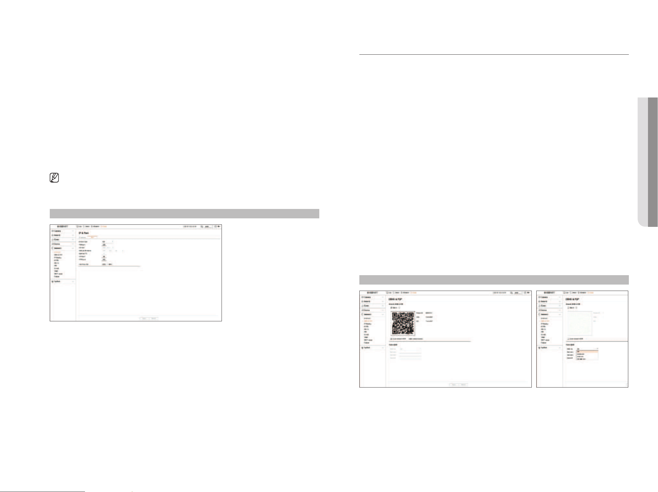
English _67
DDNS & P2P
A remote user can network a recorder using a DDNS address in a dynamic IP system. If you cannot connect with a
dynamic IP, you can easily access using a P2P service.
Accessing using DDNS address in the dynamic IP environment
In the dynamic IP environment such as xDSL/Cable modem, the router's WAN IP can be changed, so we provide
DDNS (Dynamic Domain Name Server) service so that you can always access the recorder with only the DDNS
address even in the dynamic IP environment.
Before using Wisenet DDNS & P2P, please set up the network connection and DDNS first.
DDNS Setting
Setting DDNS in the Recorder
Set <Protocol type> to <TCP> in the "Setup > Network > IP & Port > Port" menu of the connected recorder.
DDNS Settings of the Router
Select the corresponding menu for the network transfer protocol of the router.
Setting up UPnP of Router
Refer to the router's documentation to enable the UPnP function of the router.
Setting the Wisenet DDNS & P2P
Setup > Network > DDNS & P2P
●
Enable : Click <Enable> to test the connection to see if the current recorder can be connected remotely.
When the connection is successful, a QR code is created.
■
It connects to Wisenet DDNS first. If it does not connect to DDNS, it automatically connects to P2P.
●
Setting the DHCP IP Address of the Broadband Router
1. To access the Broadband Router's configurations, open a web browser on the local PC that is connected to the
Broadband Router and enter the router's address (ex : http://192.168.1.1).
2. At this stage, make the local PC's windows network configurations to the below example :
Example) IP : 192.168.1.2
Subnet Mask : 255.255.255.0
Gateway : 192.168.1.1
– Once connected to the Broadband Router, it prompts with password. While entering nothing to the User
Name field, enter “admin” into the password field and press <OK> to access the router configurations.
– Access the router's DHCP configuration menu and set its DHCP server activation, and provide the start and
end address.
■
Start address : 192.168.0.100
■
End address : 192.168.0.200
■
Above steps may differ from the router devices depending on the manufacturer.
Port Setting
Setup > Network > IP & Port > Port
●
Protocol type : Select the protocol type among TCP, UDP Unicast and UDP Multicast.
●
RTSP port : It is used to transmit the video over the network. The initial value is <558>.
●
UDP port : Activated when an UDP item is selected in protocol type. The initial value is <8000-8159>,
and the setting value changes in 160 units.
– UDP : It has less stability and faster speed when compared to TCP, and recommended for local area network
(LAN) environments.
●
Multicast IP address : Enter the IP address directly when selecting an UDP Multicast.
●
Multicast TTL : Enter the TTL value when selecting an UDP Multicast. The initial value is set to <5>, and enter a
value between 0 and 255.
●
HTTP port : Enter the port value for the HTTP web viewer. The initial value is set to <80>.
●
HTTPS port : Enter the port value for the HTTPS web viewer. The initial value is set to <443>.
■
HTTPS is an enhanced version of the HTTP web communication protocol. If security is important when accessing the web viewer, enable the HTTPS
port.
●
Cam proxy port : Sets the camera proxy port. The initial value is set to <10001>.
• SETUP
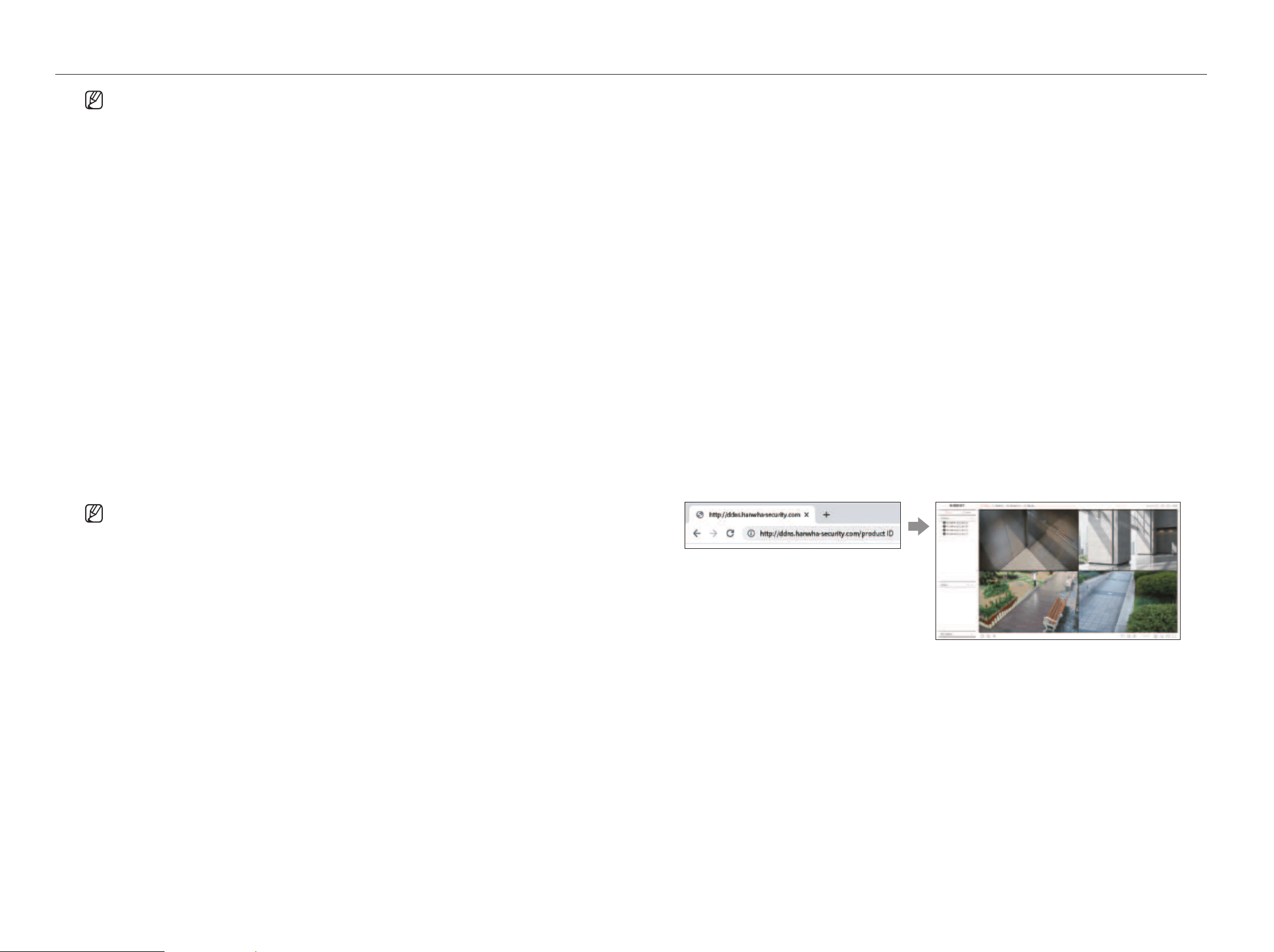
68_ setup
setup
■
In a double NAT environment or if the router's port is not configured, the DDNS status will be displayed as <Successful>, but the DDNS
connection from the viewer to the recorder may fail.
■
You must be connected to an external network for a DDNS connection. (If there are two or more networks, be sure to connect an external
network to the network set as the <Default gateway>.)
■
If you are setting up a port that is already in use, then the connection might fail. Check the port setup of your router.
■
If the viewer is connected through P2P instead of DDNS when connecting to a recorder, performance may be lower than that of the DDNS
connection. You can check the current connection method (DDNS or P2P) in each viewer.
■
DDNS is a short form of Dynamic Domain Naming System.
DNS (Domain Name System) is a service that routes a domain name consisting of user friendly characters (ex : www.google.com) to an IP
address consisting of numbers (64.233.189.104).
DDNS (Dynamic DNS) is a service that registers a domain name and the floating IP address with the DDNS server so that the domain name
can be routed to the IP address even if the IP is changed in a dynamic IP system.
●
Quick connect (UPnP) : To use the function, set to <Enable> after connecting the Recorder to a UPnP router.
The message about the progress appears when connecting to Quick connect (UPnP).
– Quick Connect Success : Message for a successful connection.
– Invalid Network Configuration : Message appears if the network configuration is not valid. Check the
configuration.
– Please enable UPnP function of the router. : Message appears if the router requires UPnP function
enabled.
– Failed to find the router. : Message appears if the router is not found. Check the router's configurations.
– Please restart the router. : Message appears if the router should be restarted.
– Quick Connect not supported in UDP mode. : Set <Protocol type> to <TCP> in the "Setup > Network >
IP & Port > Port" menu of the connected recorder.
– Connection Failed. : If the connection fails due to an unknown error, the message is displayed.
■
If there is a port conflict, it will automatically change to another port. You can check the changed port information in the "Setup >
Network > IP & Port > Port" menu of the connected recorder.
■
If there is a port conflict, check the port forwarding or UPnP settings in the user manual of the connected router.
Setting the Public DDNS
●
DDNS site : Select whether to use DDNS and the site registered when using it.
●
Host name : Enter the host name registered with the DDNS site.
●
User name : Enter the user name registered with the DDNS site.
●
Password : Enter the user password registered with the DDNS site.
Connecting to the Viewer
To connect to the Wisenet mobile from your smartphone
1. Install and run the "Wisenet mobile" app on your smartphone.
You can scan the QR code of the recorder on the <Add device> screen.
2. When the QR code is scanned, the <Product ID> shown in the recorder is automatically reflected in the
mobile viewer, and you can use the mobile viewer by entering the recorder ID/password.
3. Then, when you run the "Wisenet mobile" app, it will be automatically connected to the recorder and you can
monitor it easily with your smartphone.
To connect to the Wisenet Viewer from your PC
1. Go to www.HanwhaVision.com on your PC.
Install and run the "Wisenet Viewer" app.
2. Select <IP type> to <DDNS/P2P> in the "Setup > Device > Device list > Add > Manual" menu.
3. Enter the recorder ID/password and <Product ID>, and then click <Register>.
The information of the current recorder will be displayed, and you can use the "Wisenet Viewer" app.
To connect to the WebViewer from your PC
If you connect to ddns.hanwha-security.com/product ID including <Product ID> in the local PC address bar,
the recorder's web viewer screen will appear.
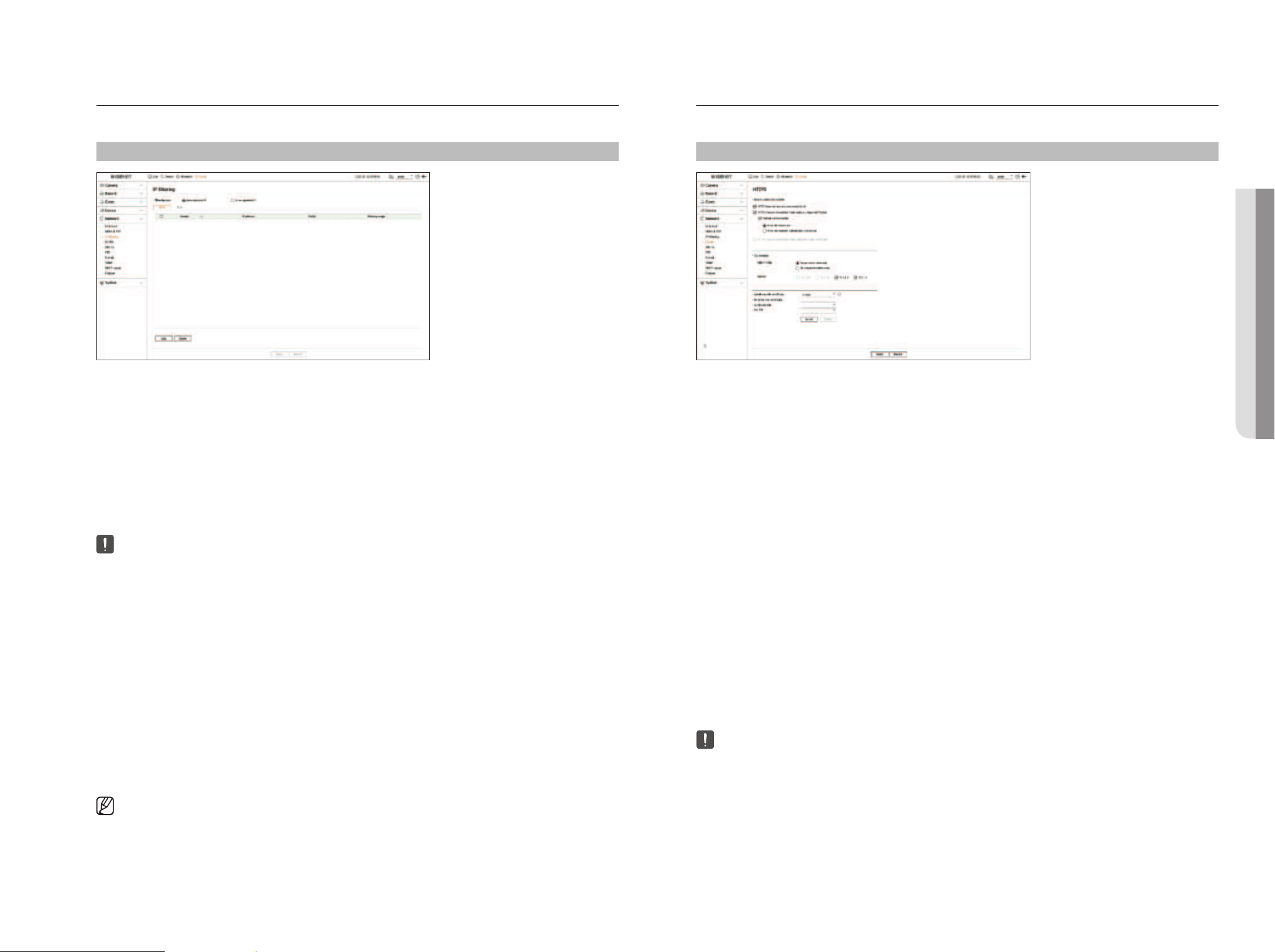
English _69
IP Filtering
You can prepare the list of IP addresses to allow or block access to a specific IP address.
Setup > Network > IP filtering
●
Filtering type
– Deny registered IP : Access to the registered IP address will be limited.
– Allow registered IP : Only registered IP addresses can be accessed.
●
Enable : Select whether to enable registered IP filtering.
●
IP address : Displays the registered IP address. Double click the IP address to change the settings.
●
Prefix : Displays the prefix to be filtered. Double-click the prefix to change the settings.
●
Filtering range : If you enter an IP address or prefix, then the range of IP addresses blocked or permitted will be
displayed.
■
If a camera's IP address is not included in the Permit list or is in the Reject list access to it will be rejected.
■
For IPv4, camera IP filtering through PoE port is not immediately applied. (Previous connections are maintained, and filtering is applied on
next login.)
To register the IP addresses to filter
1. Select the IP type tab you want to register from IPv4 or IPv6.
2. Click <Add> at the bottom of the screen.
3. When the additional window is displayed, set the details.
●
IP filtering : Select whether to enable IP filtering.
●
IP address : Enter the address to enable IP filtering.
– When entering an IP address, a value in the range 0-255 must be entered to register.
●
Prefix : Enter the prefix value.
4. Click <OK> to complete.
■
To delete a registered item, select the check box of the item to be deleted and click <Delete> at the bottom of the screen.
HTTPS
You can choose a secured connection system or install a certificate.
Setup > Network > HTTPS
●
Secure connection system : You can select a type of secure connection system based on the service
environment and the security level.
HTTPS (Hypertext Transfer Protocol Secure) is a more secure version of HTTP that exchanges data through the
encryption and decryption of the user's page request at the TLS (Transport Layer Security).
– HTTP (Does not use a secure connection) : Transmits data without encryption.
– HTTPS (Secure connection mode using a unique certificate) : Establishes a secure connection using a
unique certificate provided by the recorder.
■
Mutual authentication : Mutual authentication can be performed to enhance security. If you select <Allow all connections>, you can access
the storage device even if mutual authentication is not performed. If you select <Allow only mutually authenticated connections>, you can
access the storage device only when mutual authentication was successful.
– HTTPS (Secure connection mode using the public certificate) : Establishes a secure connection using a
public certificate. You can select this after installing a public certificate.
●
TLS settings : You can select the Cipher mode or TLS version to use for encrypted communication.
– Cipher mode : Cipher suites are provided by combining different algorithms for use in TLS-encrypted
communications, such as key exchange, authentication, and encryption.
<Secure cipher suites only> uses only high-security cipher suites.
For backward compatibility, select <All compatible cipher suites>. However, security may be poor, as it
includes all cipher suites, whether secure or not.
– Version : You can select the TLS protocol version to use for encrypted communication.
■
If <Cipher mode> is set as <Secure cipher suites only>, you can select only <TLS 1.2> or <TLS 1.3>.
■
If the recorder is connected to the external internet or installed in an environment with high priority for security, making a secure
connection is recommended.
●
Install a public certificate : You can scan and register a public certificate to be installed. To install a certificate,
you must install a certificate file or key file issued by a certificate authority. Click <Install> to register the
certificate.
■
In the <HTTPS (Secure connection mode using the public certificate)> mode, you cannot install or delete a public certificate. Change to <HTTP
(Does not use a secure connection)> or <HTTPS (Secure connection mode using a unique certificate)> mode before proceeding.
■
Install the certificate file extension as .crt and the key file extension as .key.
■
For certificate and key files, use PEM format generated by RSA (2048 or higher recommended) or ECC.
■
For certificate and key files, use PKCS#1 or PKCS#8 without a password.
• SETUP
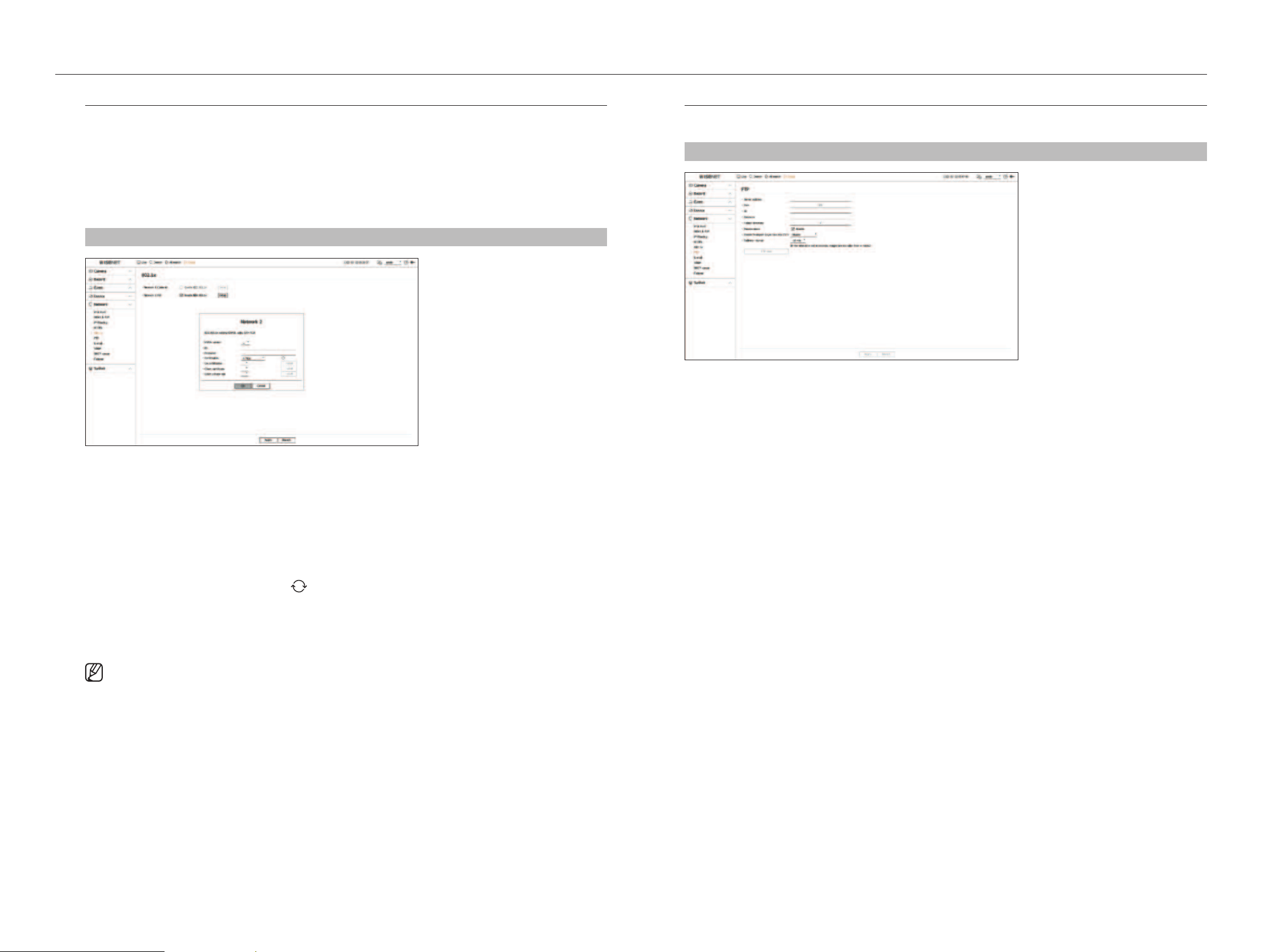
70_ setup
setup
802.1x
When connecting to a network, you can select whether to use the 802.1x protocol and install a corresponding
certificate.
802.1x is an authentication system between a server and a client, which prevents hacking, virus infection, and
information leakage of transmitted and received network data.
802.1x can be used to block the unauthorized client access and increase security by allowing only authenticated
users to communicate.
Setup > Network > 802.1x
●
EAPOL version : Select the EAPOL version to be used as protocol.
■
Some switch hubs will not operate if you set them to version <2>. Select the version <1>, which is the EAPOL default.
●
ID : Enter the ID provided by the RADIUS server administrator.
■
If the entered ID does not match the ID of the client's certificate, it won't be processed properly.
●
Password : Enter the password provided by the RADIUS server administrator.
■
If the password you entered does not match that of the client's private key, it won't be processed properly.
●
Certificates : Search for a device. Click on <
> to search for a device again.
●
CA certificates : Select this only if your public certificate includes the public key.
●
Client certificate : Select if the public certificate includes a client's authentication key.
●
Client private key : Select it if the public certificate contains the client private key.
■
For successful implementation of the 802.1x operating environment, the administrator must use the RADIUS server.
In addition, the switch hub connected to the server must be a device that supports 802.1x.
■
If the time setting of the RADIUS server, the switch hub and an recorder do not match, communication between them can fail.
■
If a password is assigned to the client's private key, the server administrator should confirm the ID and password.
The ID and password allow up to 30 characters each. (But it only supports letters, numbers and special characters ("-", "_", ".” 3 types) only.
Accessing non password-protected files is allowed without entering a password.
■
The 802.1x protocol adopted by the Recorder is EAP-TLS.
■
You need to install all three certificates to use 802.1x.
FTP
When an event occurs, it can be configured to send the event image to the FTP server.
Setup > Network > FTP
●
Server address : Enter the FTP server address to connect to.
●
Port : Enter the connection port. The initial value is set to <21>. Enter a value between 1 and 65535.
●
ID : Enter the user ID to authenticate when connecting to the FTP server.
●
Password : Enter the user password to authenticate when connecting to the FTP server.
●
Upload directory : Enter the path of the FTP server where the transmitted event image will be saved.
●
Passive mode : Check <Enable> if passive mode is required due to firewall or FTP server settings.
●
Enable Transport Layer Security (TLS) : Select between <Disable> and <TLS (if available)>.
●
Delivery interval : Select the delivery interval for your event.
■
If a series of events occurs, it will be sent at the set time, not on each event. The overlapped events that occurred during the set delivery interval are
sent as text in an html format file.
●
FTP test : Conducts the transfer test with the entered FTP server settings.
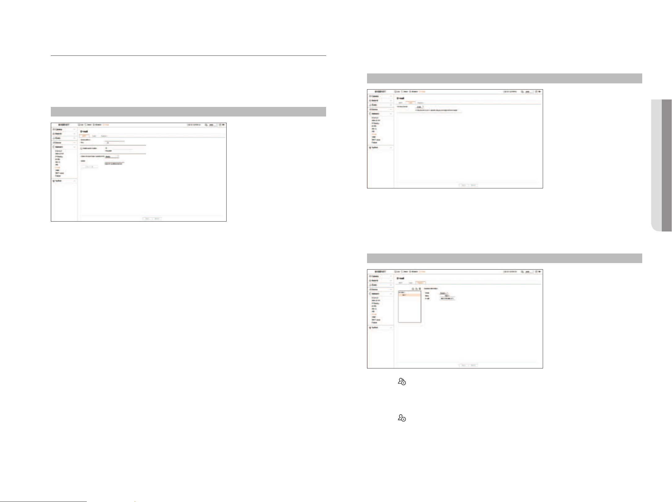
English _71
E-mail
You can send an e-mail to a Recorder-registered user at a specific time interval, or if an event occurs.
SMTP Setting
Sets the SMTP mail server.
Setup > Network > E-mail > SMTP
●
Server address : Enter the SMTP server address to connect to.
●
Port : Enter the connection port.
●
Enable authentication : Check this if the SMTP server uses user authentication.
The ID and password fields will be activated when the authentication is enabled.
– ID : Enter a ID to use authentication when connecting to the SMTP server.
– Password : Enter the password of the SMTP server user.
●
Enable Transport Layer Security (TLS) : Select one from <Disable> and <TLS (if available)>.
●
Sender : Use the virtual keyboard to enter the sender's e-mail address.
●
Test e-mail : Conducts the test on the server settings.
Event Setting
You can set the interval and type of the event that will be sent to the user.
Setup > Network > E-mail > Event
●
Delivery interval : Set the event interval.
■
If a series of events occurs, the e-mail will be sent at the specified interval, not on each event.
Recipient Setting
You can create a group and add users to it or; you can delete users and change a group.
Setup > Network > E-mail > Recipient
●
Click on < > to add a group.
Enter the group name.
●
Select a recipient group to receive emails.
If a group is added, it will appear in the group list.
●
Click on <
> to add a recipient.
Select a group and enter names and email addresses.
If a group is created, you can add a recipient.
• SETUP
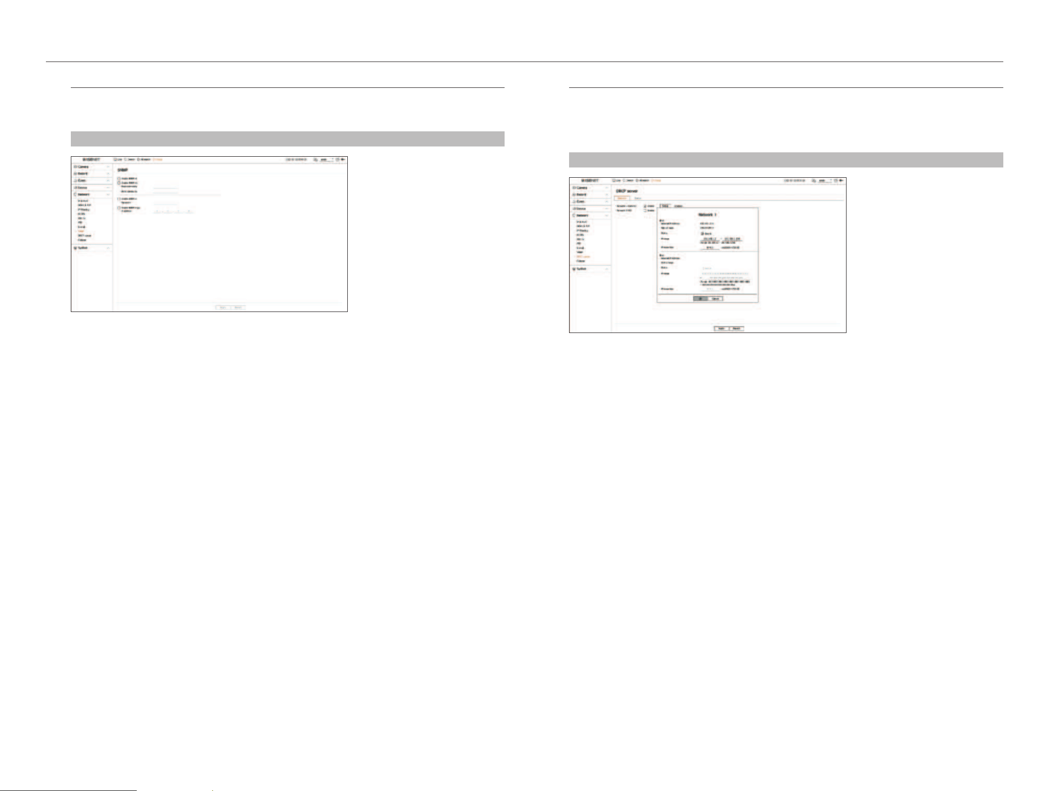
72_ setup
setup
SNMP
The SNMP protocol allows system or network administrators to remotely monitor and configure the network
devices.
Setup > Network > SNMP
●
Enable SNMP v1 : SNMP v1 is used.
●
Enable SNMP v2c : SNMP v2c is used.
– Read community : Enter the name of read-only community to access the SNMP information.
– Write community : Enter the name of write-only community to access the SNMP information.
●
Enable SNMP v3 : SNMP v3 is used.
– Password : Set the initial user password for SNMP version 3.
●
Enable SNMP traps : SNMP trap is used to send important events and conditions to the Admin System.
– IP address : Enter the IP address to which messages will be sent.
DHCP Server
You can set the internal DHCP server and assign an IP address to the network camera.
Network Setting
Setup > Network > DHCP server > Network
●
Network : You can set the IP range and time to activate as the recorder's DHCP server.
To set the DHCP server
1. Click <Setup> of the network you want to set as a server.
2. When the network setting window is displayed, select <Run> for <Status>.
3. Enter the starting IP and end IP in the <IP range> field.
4. Fill in the <IP lease time> field.
5. Click <OK>.
The IP range entered is set as the DHCP server address of the network.
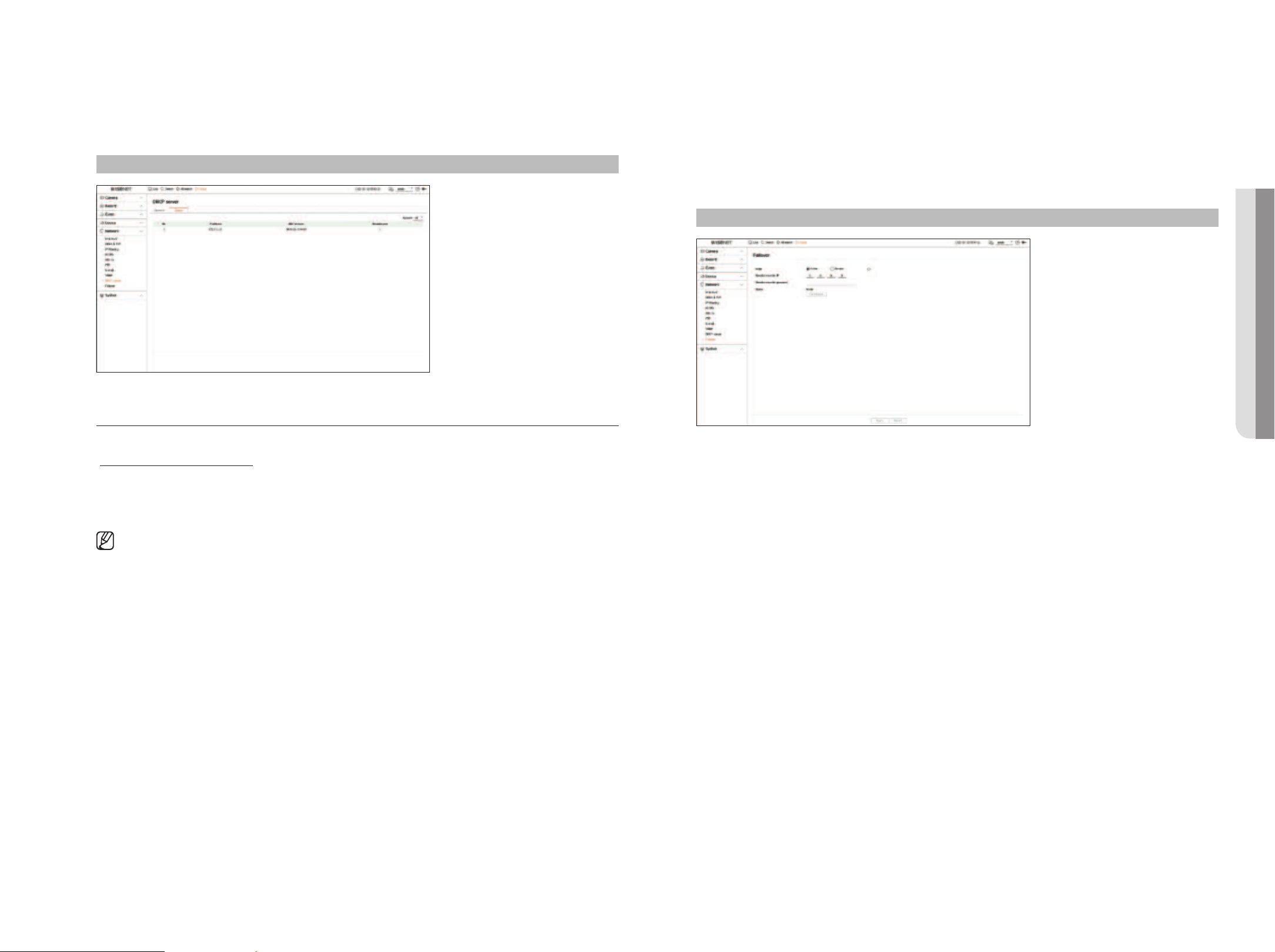
English _73
Checking the status
You can check the IP address assigned to the current DHCP server, MAC address, and the connected network port
information.
Setup > Network > DHCP server > Status
Failover
This function is only available for products that support failover. For products that support failover, refer to the
"Functions Supported by Model" page.
If the recorder cannot record due to a network failure, other recorders that have been prepared can record
instead.
You can connect 32 'Active' recorders to one 'Standby' recorder.
■
The recorder you want to configure for failover needs to be connected to both the camera and viewer ports to the local network.
■
Failover configurations can only be set with recorders of the same model.
■
Troubleshooting network interface supports IPv4 only.
■
All recorders must have time synchronized. For more information about time synchronization settings, refer to the “Setup > Setting the
System > Date/Time/Language" page in the Table of Contents.
■
The network IP band in the recorder must be set to a different band.
– Example of IP in a different bandwidth
Example 1) IP : 192.168.1.200, subnet 255.255.255.0
In the Example 1) above, since 255 of the subnet corresponds to 192.168.1, any IP in a format of 192.168.1.x has the same bandwidth.
An IP in a format of 192.168.2.x has a different bandwidth with an IP in a format of 192.168.1.x.
Example 2) IP : 172.16.1.200, subnet 255.255.0.0
In the Example 2) above, since 255 of the subnet corresponds to 172.16, any IP in a format of 172.16.x.x has the same bandwidth.
An IP in a format of 172.17.x.x has a different bandwidth with an IP in a format of 172.16.x.x.
■
For more information about network settings, refer to the “Setup > Setting the Network" page in the table of contents.
To set troubleshooting
1. Set one recorder to <Standby> mode and the other recorder to <Active> mode.
2. In the recorder set to <Active> mode, enter the viewer port IP and administrator password of the <Standby>
recorder you want to connect to and click <Connection> under the status display.
3. Check the IP and status of the connected <Active> recorder in the <Standby> recorder.
Setup > Network > Failover
●
Mode : Select either <Active> or <Standby> mode.
– Active : Recorder being recorded. Monitored by the <Standby> recorder.
– Standby : Recorder being prepared without recording. It will record instead of the <Active> recorder if a
problem occurs.
In the case of active mode
●
Standby recorder IP : Enter the viewer port ID of a standby recorder to access.
●
Standby recorder password : Enter the administrator password of the standby recorder.
●
Status : Displays the current connection status.
●
Connection / Disconnection : Click the button to access or disconnect the access.
• SETUP
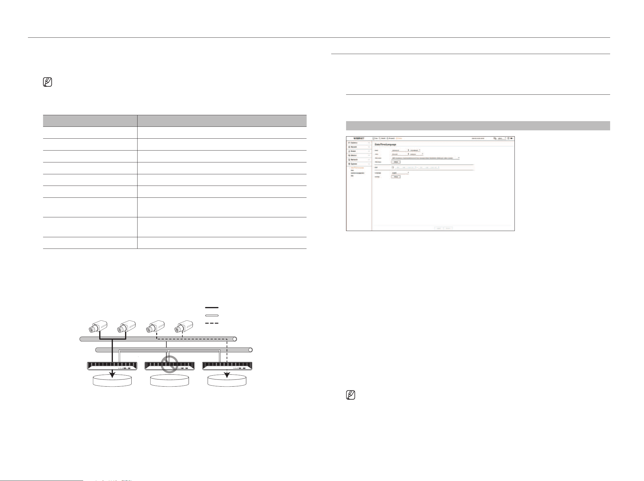
74_ setup
setup
In the case of standby mode
●
Device list & status : Shows the status of the normal recorder currently connected to the standby recorder. To
delete the normal recorder connected, click <Delete> on the right side of the recorder.
■
The standby recorder can only enable some functions in the <System>, <Device>, and <Network> menus. You can't use the
<Record> and <Event> menus.
■
In the standby recorder, the previous operation will stop when a failover is performed during the playback or section export, and the screen
will move to the live screen.
State name Description
Ready Ready to be connected
Connected Normal recorder and standby recorder connected (failover available)
Failover Troubleshooting is being performed
Connected fail Connection was attempted but failed
Authentication failure Auth failed by entering an incorrect standby password when attempting to connect
Connected(Match Time Required) Connected without time synchronization with the standby recorder
Connected(check camera port IP)
Even if the camera port of a normal recorder is connected to the viewer port of the standby
recorder or connected to the same viewer port, the IP port of the camera port is not matching.
Connected fail(check camera port IP)
The connection from the normal recorder's camera port to the standby recorder's camera port
failed.
Connected fail (It is a different model.) Failed connection by connecting recorders of different models.
Example of setting up failover
– Subnet 1 ➡ Network 1 (Camera)
– Subnet 2 ➡ Network 2 (Viewer)
– Subnet 3 ➡ Network 3 (iSCSI)
Subnet 1
Active Active Standby
Subnet 2
Recording Stream
Failover Monitoring
Fake Recording Stream
SETTING THE SYSTEM
You can set the date, language, authority, etc. displayed when using the system, and query system information or log
information.
Date/Time/Language
You can check and setup the current Date/Time and time related properties, as well as the language used for the
interface on the screen.
Setup > System > Date/Time/Language
●
Date : Sets the date and its format that will appear on the screen.
●
Time : Sets the time and its format that will appear on the screen.
●
Time zone : Sets the time zone of your area based on the Greenwich Mean Time (GMT).
■
GMT (Greenwich Mean Time) is standard World Time and the basis of world time zone.
●
Time sync : Specify the use of synchronization with the time server.
Click the <Setup> button to display time synchronization setup screen.
If you enable <Synchronize with NTP server>, the current time of the recorder is synchronized by the server
specified in <NTP server address>, and the time information cannot be manually changed.
– Synchronize with NTP server : Specify the use of synchronization with the time server.
– NTP server address : Enter an IP or URL address of the time server.
– Last sync : Displays the most recent synchronization time from the selected time server.
– Enable as NTP server : If you select <Enable>, this recorder will act as a time server for another recorder or
network camera.
●
DST : Set up Daylight Saving Time with its period to make the time earlier than the GMT of its time zone by 1
hour during the set period.
●
Language : Select your language. Sets the language for the interface.
■
Depending on the location of the product release, the language and standard time setup may vary.
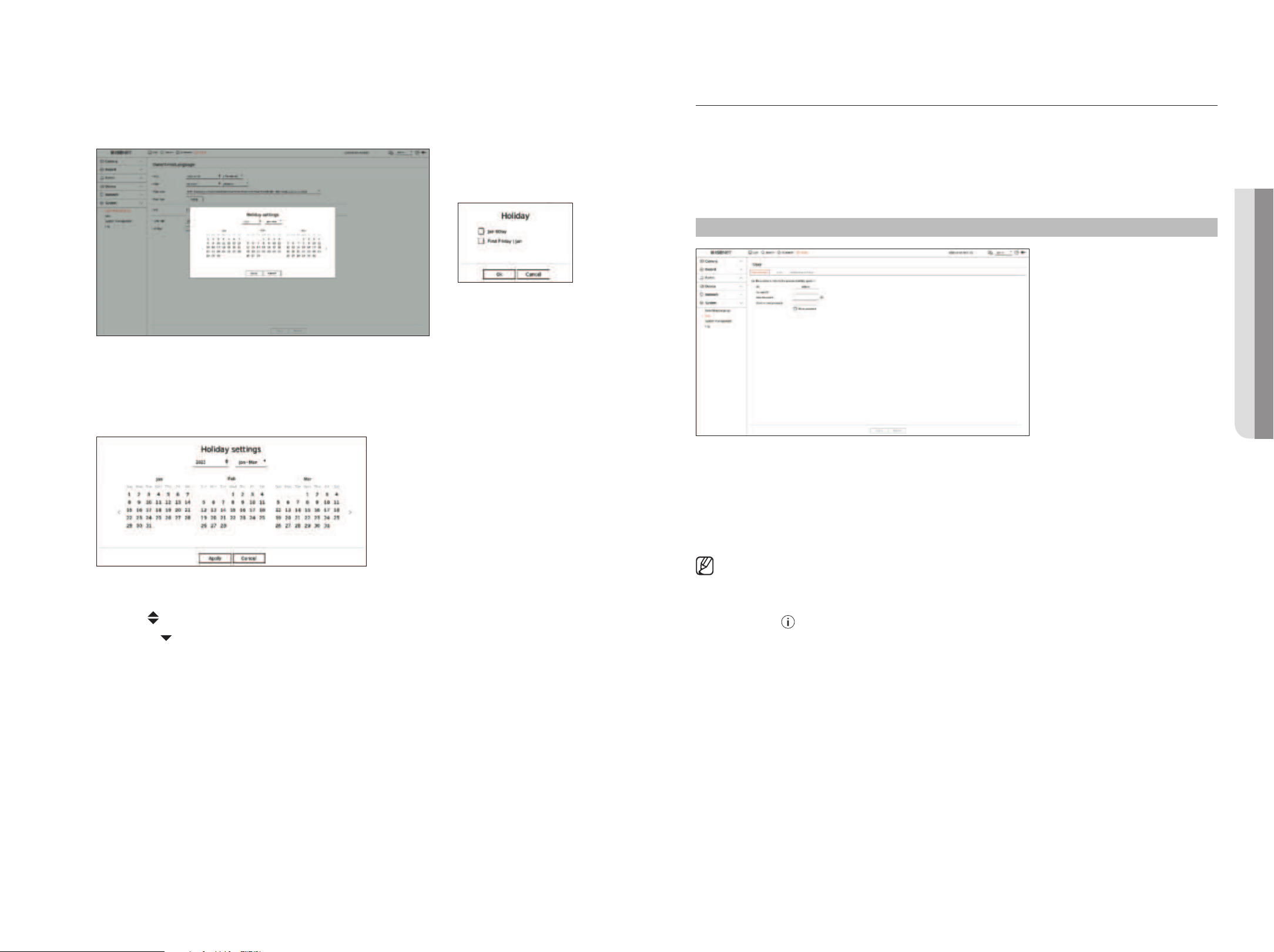
English _75
●
Holiday : A user can select specific dates as holidays according to their own preferences. Select a holiday from
the calendar displayed by clicking <Setup>.
– The same applies to <Record schedule> or <Schedule> settings as holidays.
Example) If you select Jan 6 and check <Jan 6Day>, Jan 6 will be set as a yearly holiday, and if you check <Jan
6Day> and <First Friday l Jan> Jan 6 of every year and all Fridays of the first week of Jan will be set as holidays.
To use the calendar
1. Select year and month.
■
Click < > on the right side of the year to change the year by one year.
■
Click the < > to the right side of the month to change the month every 3 months.
2. Select a date and click on the <Apply> button.
User
You can manage users, such as adding or deleting users and granting different authorities for each user.
Setting the Administrator
You can set and change Administrator's ID and password. The administrator can use and set all menu items and
functions.
Setup > System > User > Administrator
●
ID : Change the admin ID.
●
Current PW : Enter the current PW.
●
New password : Enter new password.
●
Confirm new password : Enter the new password again.
■
If <Show password> is selected, the password will no longer be hidden on the screen when you type it.
■
The initial administrator ID is set to “admin” and you will need to configure the password in the installation wizard.
■
Please change your password every three months to safely protect personal information and to prevent the damage of the information
theft.
Please, take note that it's a user's responsibility for the security and any other problems caused by mismanaging a password.
■
If you click < >, a basic guide for password setup is displayed.
• SETUP
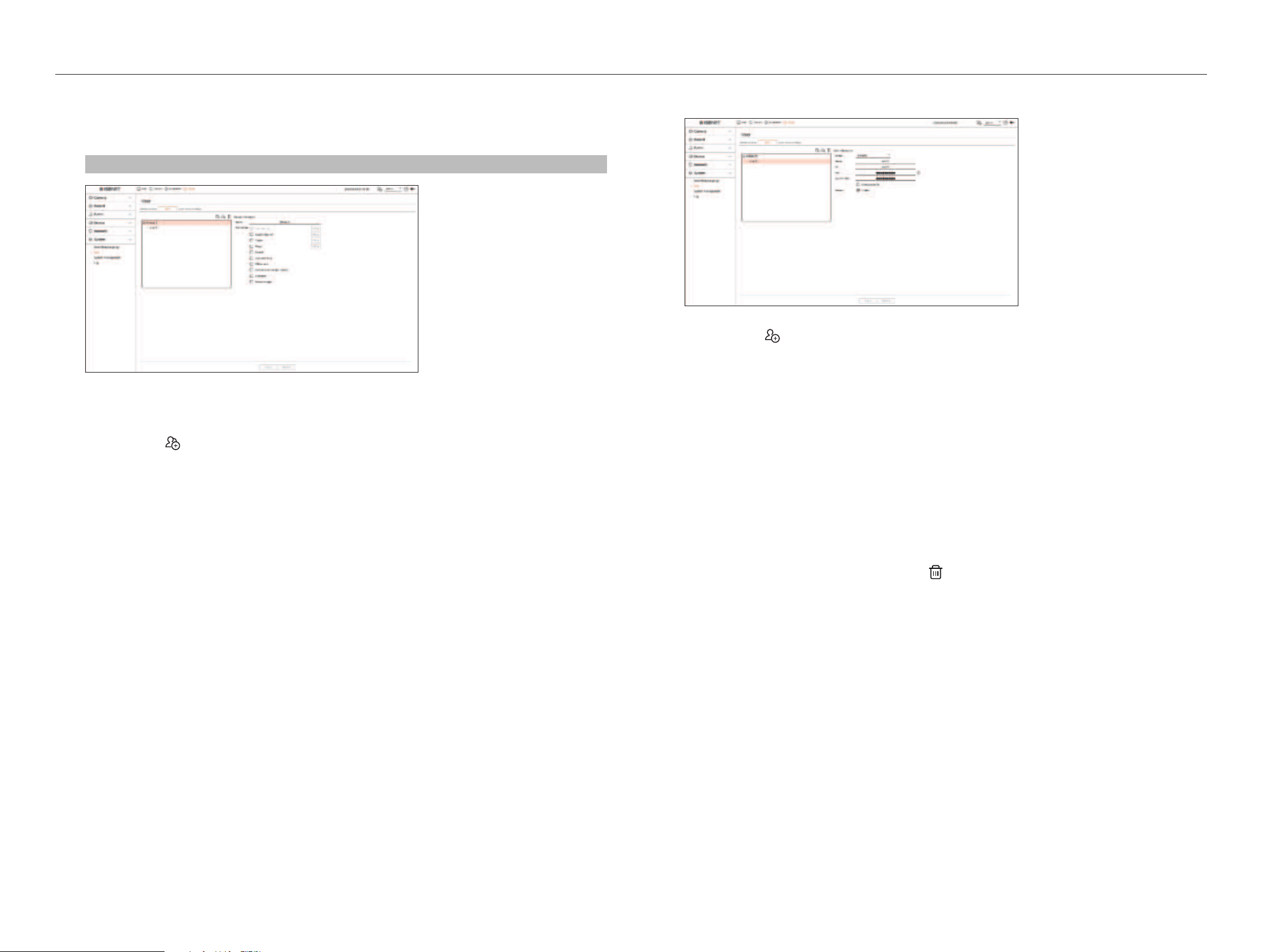
76_ setup
setup
User setting
You can create user groups and set authorities for each group. You can manage user information such as
registering and deleting users in the created user group.
Setup > System > User > User
If you want to add a group
1. Click on the <
> button to launch the Group Addition popup window.
If you want to add a group, click on <OK>.
2. If you click the group name item on the right, a virtual keyboard to enter the group name will appear.
Enter the group name to register.
■
You can add a maximum of 10 groups.
If you want to set group permission
Set the access authority of the group.
Users in the group can only enable the menu to which they have been granted authority.
1. Select the menu to set group permissions.
Set the menu and click <Setup> on the right to display the detailed settings window.
●
Live channel : You can set permissions to access the live screen for each channel.
●
Search channel : You can set permissions to access the search menu for each channel.
●
Export : You can set the authority to access the export menu for each channel.
●
Menu : You can select and set the setting menu that can be accessed. A group user can only access the
menu selected. If you select the menu, the menu permission setting screen will be displayed.
■
Even if you select "System > System management > Settings" in the <Menu permission> setup window, <Factory default> and
<Power down> access rights are excluded.
●
Record, Stop recording, PTZ control, Remote alarm output control, Shutdown : You can set the menu to
grant access to users in the group.
■
Permission-set menus will show up in the Live menu when users of the group log in.
2. Select <Apply>.
Users in the group will be given access to the set items.
If you want to register a user
1. Click on the < > button to launch the user addition popup window.
To add a user, click on <OK>.
2. Select a group.
When registering a user, the selected group will be automatically registered.
■
You can change the group after entering all the user information.
3. Enter a name, ID and password (confirm password) and enable or disable the viewer option.
If you activate use of <Viewer>, you will have the right to use the web viewer and the network viewer.
■
If <Show password> is selected, the password will no longer be hidden on the screen when you type it.
4. Click <Apply>.
Registered user information will be saved.
When you want to delete the group and user information
1. Select the group or user to delete and press the <
> button.
2. The deletion confirmation window will appear and click on <OK>.
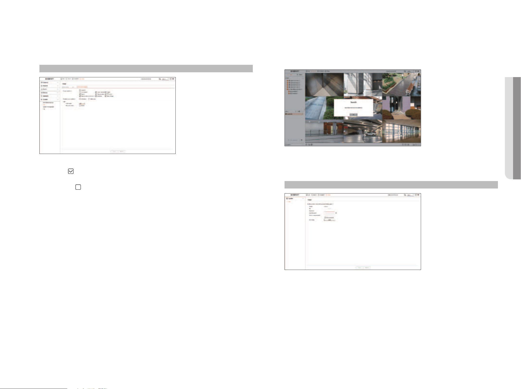
English _77
Restriction Settings
Set user's restricted access or network restriction.
Items with restrictions will require logging in for use.
Setup > System > User > Restriction settings
●
Access restriction : You can set the menu to restrict the access for user.
– Checked (
) : Restricted
■
Only those users who were given Permission for the menu in <User> can access the menu.
– Not checked (
) : Accessible
■
Regardless of the Permission settings for the menu in <User> all users can access the menu.
●
Remote access restriction : You can restrict remote access for users.
– All viewers : Set all users to be unable to access the network and the web viewer.
– Web viewer : Set all users to be unable to access the web viewer.
●
Auto logout : A user will be automatically logged out if there is no operation on Recorder for over set period of
time.
●
ID manual entry : In the login window, select whether to enter ID.
If the user has restricted access
If a general user selects a menu to which they do not have access, an access restriction confirmation window will
be displayed. If all rights are restricted, only the accessible menu of the live screen menu will be displayed, and
only the user's own password can be changed.
To change the user password
If you log in with the user account of a group with restricted access, you just can change your own password.
Setup > System > User
1. Provide the login information.
2. Select <User> in <System>.
3. Please enter your current password.
4. Provide a new password. Enter the password you want to change in the password confirmation box again.
5. Select <Apply>.
The old password will be changed to a new one.
• SETUP
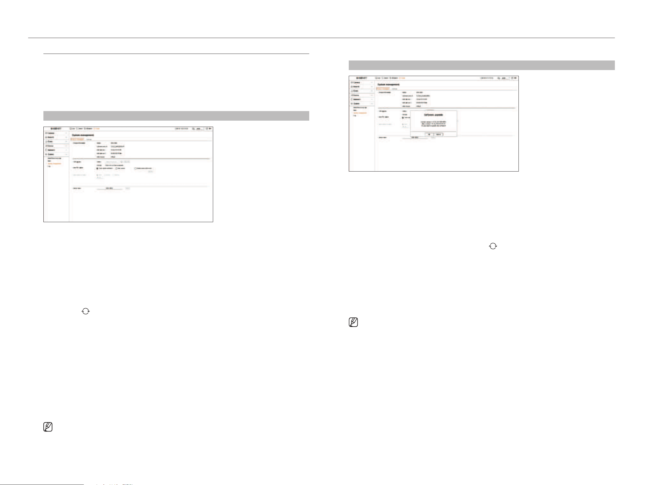
78_ setup
setup
System Management
You can check the current system version and update to a new version, export data, setting initialization, and
more.
Checking the System information
You can check the current software version and MAC address before proceeding with the upgrade.
Setup > System > System management > Product information
●
Product information : Shows the current system's information.
– Model : Shows the model name of the product.
– Software version : The software version of the product currently being used is displayed. You can check the
software version and upgrade to the latest version.
– MAC address : Shows the Mac address of the product.
– UWA version: Shows the UWA version of the product.
●
S/W Upgrade : Updates the Recorder's software up to date.
– If hard disk is unavailable or not properly connected, the software upgrades do not appear.
– Press the <
> buttons to search for the software in the USB or on the network.
– When the updating is done, it automatically restarts. Make sure to not turn off the power during upgrade.
●
Auto FW update: When the network is connected to a recorder, you can receive new firmware notifications.
After selecting the setting you want, click <Apply>.
– Enable update notification : You will get a notification when there is new firmware.
– Auto updates : It checks if there is new firmware on the set date, day, or time, and automatically updates if
there is one.
– Disable update notification : It does not check for the presence of new firmware.
●
Auto update schedule: It activates when you select <Auto updates> in the <Auto FW update>.
Select the date, day, or time to automatically update when new firmware is available.
●
Device name : You can enter a device name for your product. To differentiate multiple recorders in VMS, Device
Manager, etc., it is recommended to enter a different device name for each device.
■
The system information displayed may differ depending on the recorder model.
To upgrade the current software version
Setup > System > System management > Product information
1. Connect a device storing the software to be updated.
■
It may take about 10 seconds to recognize the device.
■
Upgradeable devices include USB memory, and network device.
■
If you want to upgrade it on the network, the product should be connected to an external network.
Upgrade via the proxy server may not be enabled due to the restricted access.
2. When the recognized device appears, select <Upgrade>.
■
If you connect a device in the upgrade menu window, you can press the < > button to search for available software.
■
If there is an upgraded version on the network, a popup window will appear.
■
<Upgrade> will be activated only when there is a higher version than the current software version.
3. In the <Software upgrade> window, select <OK>.
■
While updating, it shows the progress.
4. When the updating is done, it automatically restarts.
Do not turn the power off until it finishes restarting.
■
If “Upgrade Failed” appears, retry from the step 2. When you experience continued failure, consult the service center for assistance.
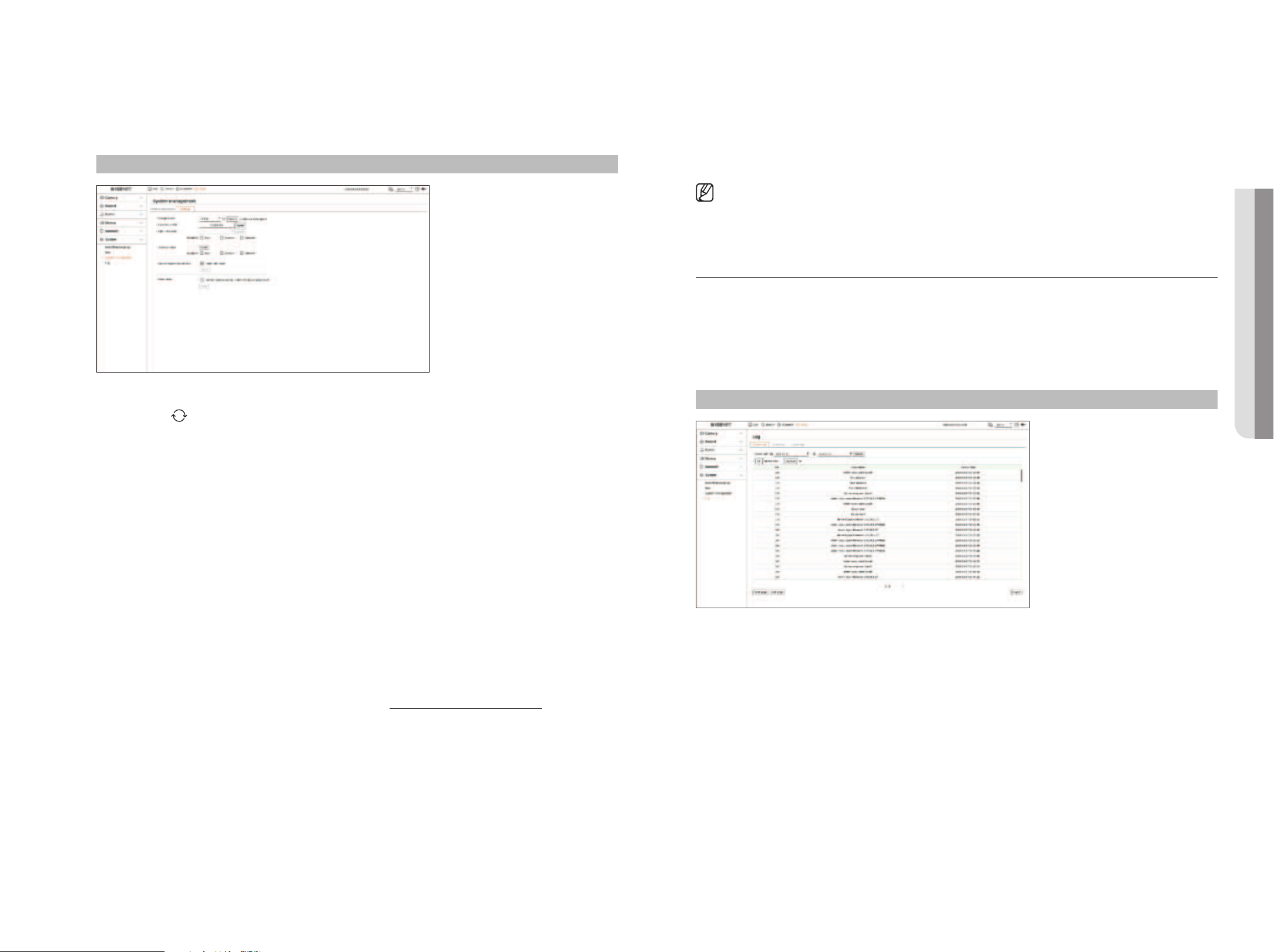
English _79
Settings
You can export the information set in the recorder to a storage device and apply the same information to other
recorders.
Setup > System > System management > Settings
●
Storage device : Shows the connected storage device.
– Press the <
> button to view the list of storage devices.
– If you click <Format>, the format confirmation window will appear. Click <Ye s > to format the selected
storage device.
●
Recorder ➡ USB : Save the information set in the recorder to a storage device.
– If you select <Export>, a confirmation window will appear. If you select <OK>, the recorder information will
be saved as a file.
●
USB ➡ Recorder : Apply the setting information stored in the storage device to the recorder.
– If you select the exclusion setting, you can import all information but the selected information.
– If you select <Import>, you can recall the setting information stored in the storage device. Select <OK> to
apply the loaded information to the recorder.
■
The <Export> and <Import> settings can be used in the same software version only.
●
Factory default : Resets the product to its factory default settings. However, logs won't be reset. Anything
selected under Exclusion Setting won't be part of the factory reset.
A confirmation pop-up will appear when you press the <Reset> button. Select the <OK> button to reset the
selected items.
●
Camera registration method : Set the camera registration method. This function is only available for products
that support PoE. For products that support PoE, refer to the "Functions Supported by Model" page.
– Enable PnP mode: Cameras connected to the PoE port of the product will automatically be registered for
each channel in order of port number.
■
When the camera resets to factory defaults, it defaults to the ID and password set in the "Setup > Camera > Camera password" menu.
If the camera ID and password are not set, the recorder ID and password will be set automatically.
■
If the camera's ID and password have already been set, the information that matches the ID and password set in the "Setup > Camera > Camera
password" menu will be registered (up to 3 sets).
■
You may change the passwords of registered cameras all at once in the "Setup > Camera > Camera password" menu.
■
If manual mode is used, you can register cameras connected to the recorder’s PoE port and cameras connected to a separate switch in the <Channel
setup> menu. For more details on camera registration, see the "Setup > Setting the Camera > Setting the Channel” page in the Table of
Contents.
●
Power down : If the power is off, the first alarm is generated. Select the <Use the alarm output no. 1 when the
device power is off> check box and click <Apply> to clear all alarms set for alarm output 1, and then selecting
alarm 1 with another alarm out will not be possible.
■
This function is provided only for products that support alarm output.
■
If that function is set, the first alarm-out checkbox and all alarms in the alarm setup screen are deactivated, to Off.
■
If you export setup information, then the data will be saved as a file in the recorder folder of your storage device.
■
If you want to import setup information, you have to first make sure that the setup information file is located in the recorder folder of the
storage device.
Log
You can check the log information related to system, events, and export.
Checking the system log
System Log shows log and timestamp on every system start up, system shutdown, and changes on system
settings.
Setup > System > Log > System log
●
Search date : Click the Calendar icon to display the calendar window, or use the direction buttons to specify the
search period of the system log.
●
Search : Specify the date and press this button to display the search result in the log list.
●
CH : Select a channel to search.
●
Log type : When there are too many logs, you can display logs of the desired format by selecting the type.
Select the desired type and click <Apply>.
●
First page/Last page : Move to the first/last page when there are many search results.
●
Export : Save all the logged information recorded in the Recorder into the storage device.
• SETUP
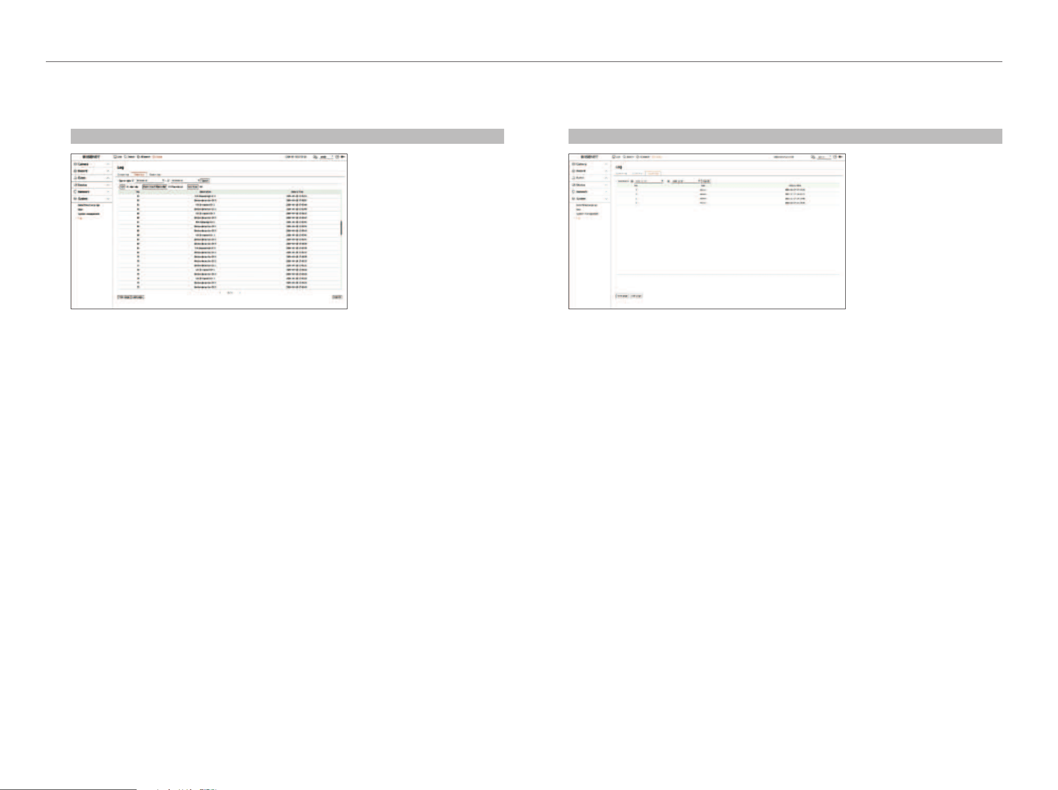
80_ setup
setup
Checking the event log
You can search recorded events including alarms, camera events and video loss.
It also shows the log and its timestamp.
Setup > System > Log > Event log
●
Search date : Select the date to search the event log by using the calendar window that appears when the
calendar icon is selected or by using the arrow buttons.
●
Search : Specify the date and press this button to display the search result in the log list.
●
CH : Select a channel to search.
●
Alarm input (Recorder) : Select the alarm of the recorder to be searched.
●
Log type : When there are too many logs, you can display logs of the desired format by selecting the type.
Select the desired type and click <Apply>.
●
First page/Last page : Move to the first/last page when there are many search results.
●
Export : Save all the logged information recorded in the Recorder into the storage device.
Checking the export log
You can search the user who performed the export and the execution time and details (time, channel, device, file
type).
Setup > System > Log > Export log
●
Search date : Select the date to search the export log by using the calendar window that appears when the
calendar icon is selected or by using the arrow buttons.
●
Search : Specify the date and press this button to display the search result in the log list.
●
First Page/Last Page : Move to the first/last page when there are many search results.
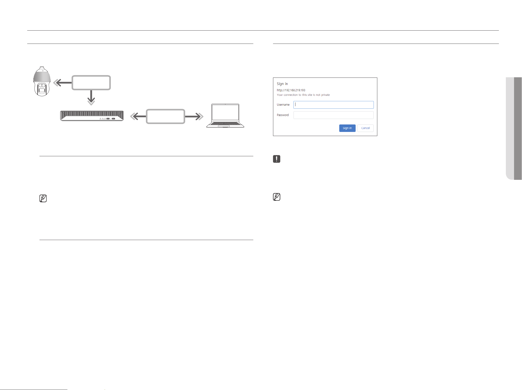
English _81
What is Web VieWer?
Web Viewer is a software program with which the operator can access a remote Recorder for real-time monitoring, PTZ
control (if configured) or search.
NETWORK
NETWORK
Recorder
Network Camera
Remote PC
Product Features
●
Remote connection using the browser
●
PTZ camera control enabled
●
Split mode supported
– 2-split vertical, 2-split horizontal, 3-split, 4-split, 6-split, 1+5-split, 1+7-split, 9-split
■
Depending on the number of channels supported by the product, the number of screen split modes may vary.
●
Takes a screenshot and saves images in PNG format
●
Record video in AVI format-compatible with popular media players. (The integrated codec is needed)
system requirements
The following lists the minimum suggested hardware and operating system requirements needed to run the Web
Viewer.
●
Use the browser recommended by the OS.
Ex.) Microsoft recommended browser: Microsoft Edge
●
Supported browsers : Chrome, Edge, and Safari
●
Supported OS : Works on all of the Windows, Linux, and OS X environments given the platform-independent
nature of the web.
●
Tested environments : Tested and certified to run on Windows® 10 with Edge 91, Google Chrome™ 91 and Intel®
Core™ i7-7700 processor 3.60 Ghz with NVIDIA® GeForce® GTX™ 1050 or Intel™ HD Graphics 630.
●
Performance restrictions : The performance of users' CPU/GPU may impact the video playback performance of
the web viewer. The video quality may decrease depending on the settings, such as high resolution or transfer
bandwidth, when playing H.265 video in Chrome.
ConneCting Web VieWer
1. Open your web browser and type the IP address or URL of Recorder into the URL address box.
2. A user with the admin permissions should provide the admin ID and password.
A registered user should provide the user ID and password.
3. After you log in, the Live Viewer main screen appears.
■
All settings are applied according to the Recorder settings.
■
If you change the web port when connecting to the Webviewer, you may fail to access since the applicable port is blocked. In this case, change the port
to a different port.
■
Please change your password every three months to safely protect personal information and to prevent the damage of the information theft. Please,
take note that it's a user's responsibility for the security and any other problems caused by mismanaging a password.
■
It allow s up to 10 simultaneous access including the admin and general users.
■
Password of the admin and general users can be changed in <User> menu of the Recorder.
■
Normal users should have set <Web viewer> under <Remote access restriction> to Use before connecting to the Web Viewer.
For details, refer to the "Setup > Setting the System > User” page in the Table of Contents.
■
All settings are applied according to the Recorder settings.
starting web viewer
• starting Web VieWer
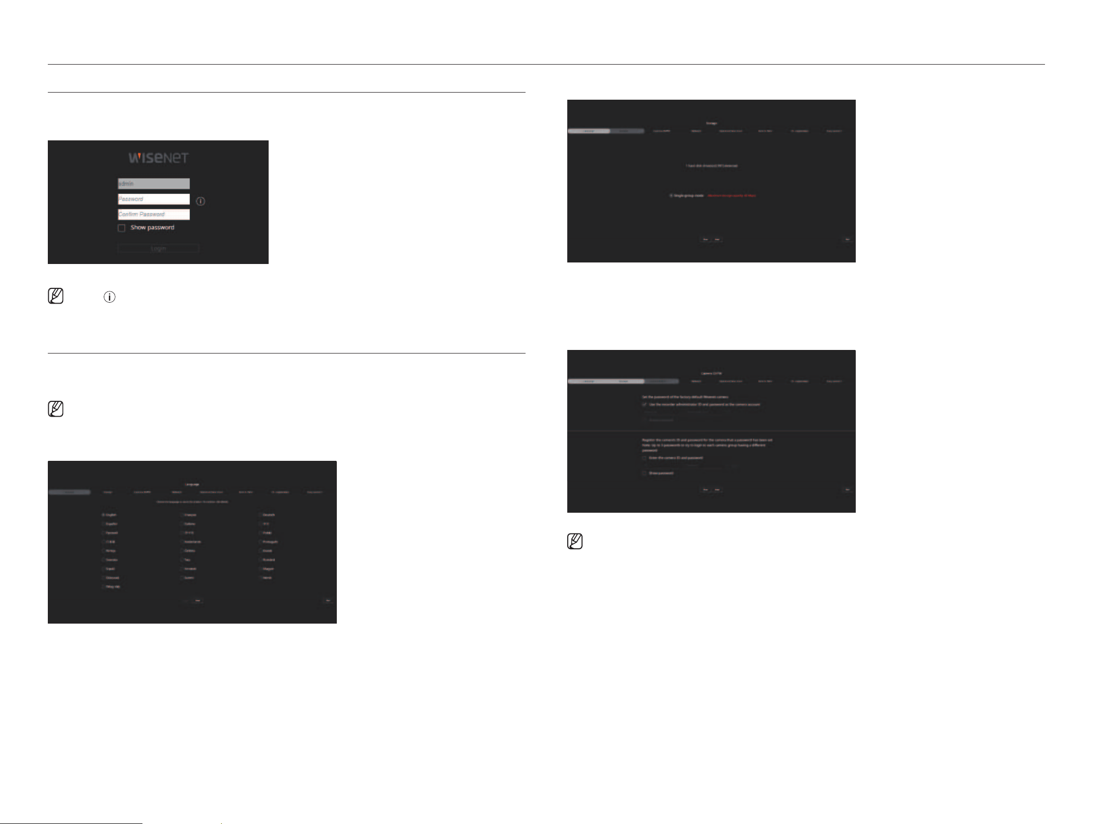
82_ starting web viewer
starting web viewer
set the reCorder PassWord
After factory reset, the password must be set for the recorder to access the web viewer.
Enter the password of the admin account, and click <Login>.
■
Click < > to view the basic guide for setting a password. Refer to the password setup rules.
instaLLation Wizard
As shown below, proceed through each step of the <installation wizard>.
Install Wizard can only be accessed at factory reset. If you do not want to proceed, click <exit>.
■
When you complete installation using the install wizard on your recorder, the install wizard will not appear on your web viewer.
1. In the <Language> screen, select the language and
click <next>.
2. Set the video recording method on the <storage> screen, and then click <next>.
●
Single group mode : Saves data on one hard disk. If the hard disk is recognized as an unusable hard disk in the
recorder, the data can be saved after formatting the hard disk.
3. Set the camera password in factory reset on the <Camera id/PW> screen.
If ID/PW is already set in the camera, register the ID/PW and click <next>.
■
When the password is in factory reset, it can be changed and managed in a batch.
■
Up to 3 sets of camera ID with password and password can be registered.
■
You may change the passwords of registered cameras all at once in the "Setup > Camera > Camera password" menu.
■
You cannot change the password for cameras registered with ONVIF and RTSP.
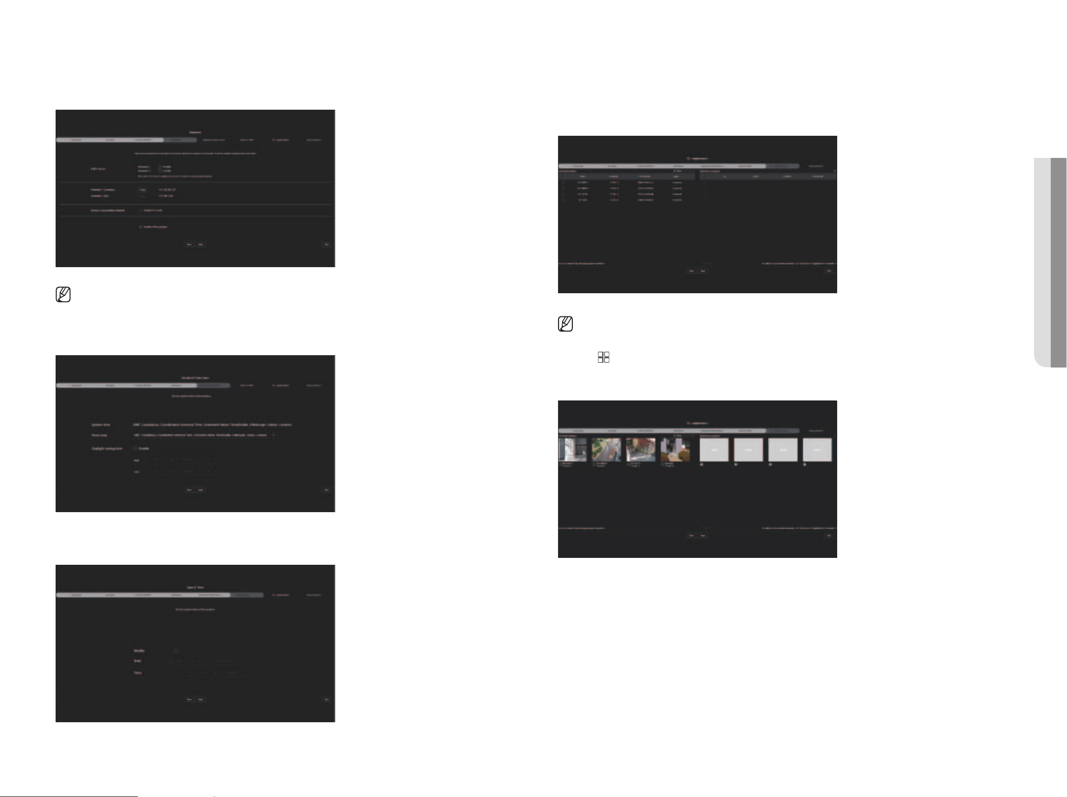
English _83
4. Set the network connection type and the connection environment on the <network> screen, and then click
<next>.
■
For details on network settings, refer to the "Getting Started > Installation wizard" page in the Table of Contents.
5. Set the standard time zone on the <standard time zone> screen, and then click <next>.
To set <daylight saving time>, select the <enable> check box.
6. To modify the date and time on the <date & time> screen, select the <Modify> check box.
Set the date and time, and then click <next>.
7. On the <Ch. registration> screen, select a camera to register from the searched camera list and then click
<register>.
Select a camera to register from the list and then click <Change iP>.
After camera registration, click <next>.
■
After entering the ID and password set in the camera, the connection test must be completed for successful registration.
8. Click <
> to see the camera videos registered to each channel in a split screen with thumbnail.
To change the camera video position, select a video and drag and drop it to the desired location.
After a channel setup, click <next>.
• starting Web VieWer
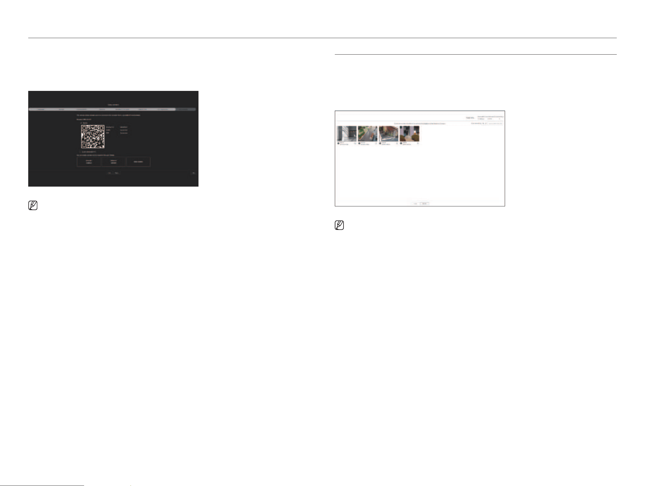
84_ starting web viewer
starting web viewer
9. On the <easy connect> screen, a remote user can network a recorder in a dynamic IP system.
Click <enable> to test the connection to see if the current recorder can be connected remotely. When the
connection is successful, a QR code is created.
To connect a recorder via a viewer, select the viewer you want to use. You can check the connection method of the
selected viewer in the popup window.
■
It connects to Wisenet DDNS first. If it does not connect to DDNS, it automatically connects to P2P.
10. Click the <next> button to complete the installation wizard.
CaMera setuP
When the installation wizard closes, the camera setup screen will automatically appear.
Based on the registered camera's record profile information, you can check the total bandwidth, expected space, and
expected days.
You can change camera setup and the record schedule, and apply the same settings to other channels.
For details, refer to the "getting started > Camera setup" page of the table of contents.
■
The camera setup screen is also displayed when registering a camera for the first time in the "Setup > Camera > Channel setup" menu.
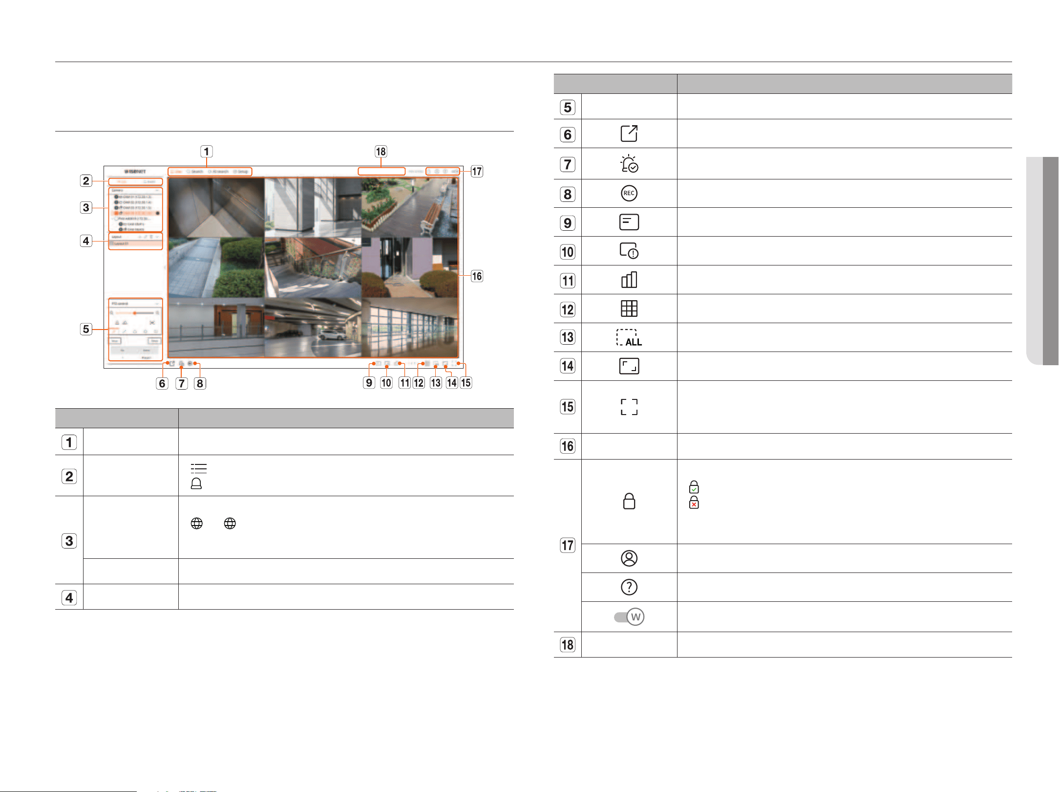
English _85
live viewer
Menu Description
PTZ Control Controls the connected PTZ camera.
Saves the video saved in the set time of the selected channel in PC in AVI format.
Clears the alarm in the event list and stops the alarm/beep sound for the system status when it is emitted.
Enables the Manual recording function of the recorder.
Displays the information on the OSD screen in the video window.
Shows the selected Channel Information.
Shows the status of all cameras connected to the recorder.
Sets the split screen of the video window.
Removes all screens from the video window.
Shows the video in actual proportions.
It changes to full screen from the current Split Mode.
To exit full screen, press the ESC key on your keyboard.
■
MAC Safari does not support full screen.
Video window Shows the video of the camera connected to the recorder.
Displays the IP address and mutual authentication status of the viewer receiving the video from the recorder.
●
: Mutual authentication connection using WISENET device certificates
●
: Mutual authentication connection without WISENET device certificate
●
– : Connection without mutual authentication
●
No viewer connected : Displayed when there is no viewer connected to the recorder.
The ID of the connected user is displayed.
You are directly connected to the Hanwha Vision homepage (www.HanwhaVision.com).
Changes the color theme of Web Viewer.
System status display Displays the status of the system, hard disk, and network.
• LiVe VieWer
You can check the video from camera registered in the Recorder connected from a remote PC. Also, you can adjust the
camera and check the network transfer status.
sCreen Layout oF the LiVe VieWer
Menu Description
Menu Click each menu to go to the corresponding menu screen.
List/Event
●
List
: Select to check the camera list.
●
Event
: Select to check the event list
Camera list
The list of cameras registered in the recorder is displayed.
●
: The < > icon is displayed when you mouse over the camera list. Click the icon to go to the camera web page.
To go to the camera webpage, you must have the right to set cameras, profiles, and events, and set <Video> to <On>
in the "Setup > Camera > Channel setup" menu.
Event list Shows a list of events that occurred on the camera.
Layout list Displays the default layout and a list of created layouts.
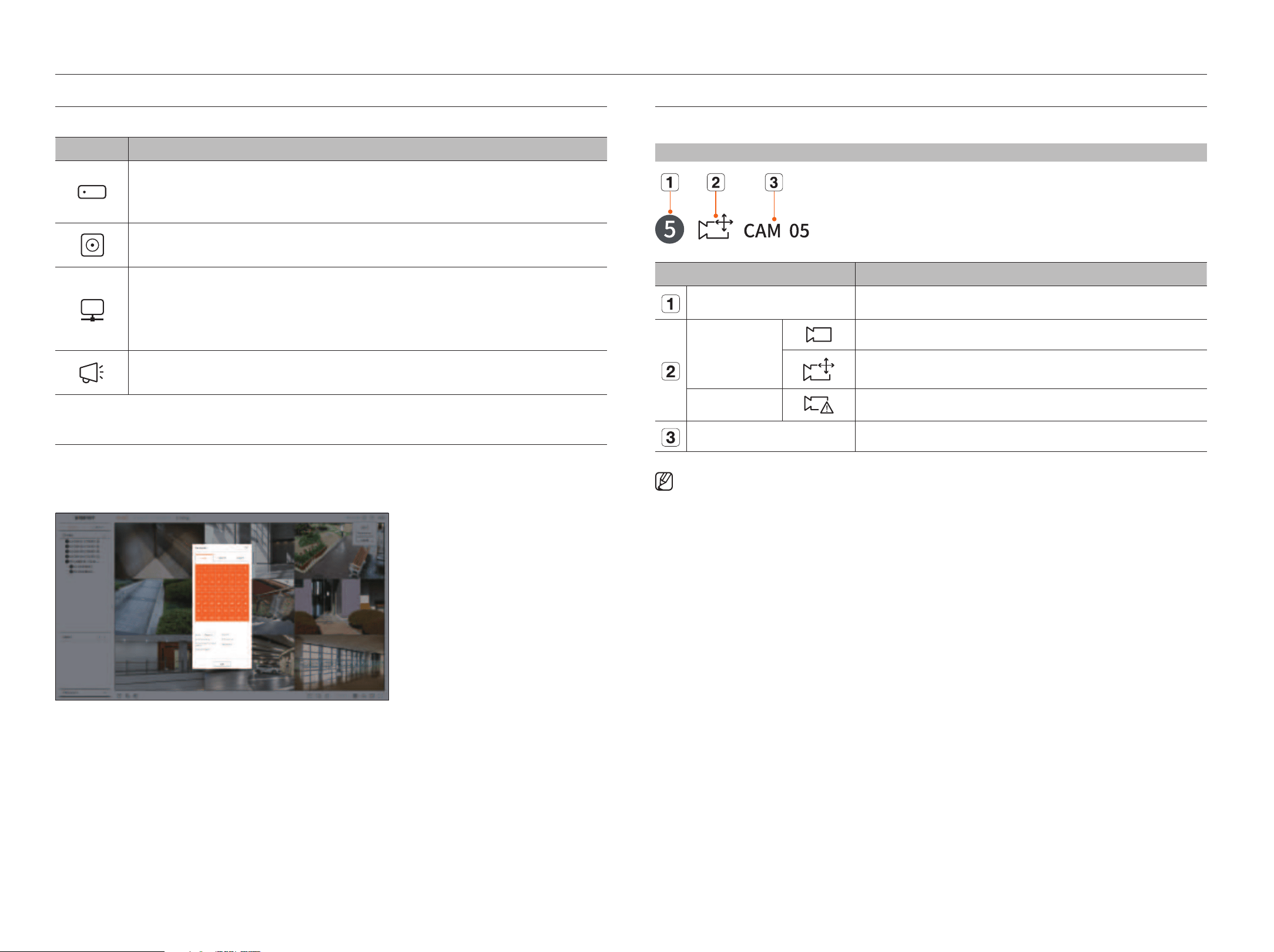
86_ live viewer
live viewer
CheCking CaMera List
Displays the camera type, status, and name registered in the recorder.
Live > List
Name Description
Channel information Displays channel information (channel number, video window assignment, and color indication).
Camera type
Displays a normal camera.
Displays a PTZ camera.
Camera status
Displays the camera error status.
Camera name Displays the name set for the camera.
■
If a camera connection error occurs, it is disabled in the list.
■
The camera status display information changes according to the network connection status and settings.
■
For multichannel cameras registered with the Wisenet protocol, the channel information will be displayed under the model name of the multichannel
camera.
■
In case of multichannel cameras, only one main channel can be registered for recording.
Subchannels in which recording is not required do not need to be registered on the recorder, as they can be monitored real time. However, recording,
event reception, or camera settings are not available.
CheCking the systeM status
The icon at the top of the screen indicates the status of the system.
Name Description
Displayed when a problem occurs with the recording status.
Displayed when an error occurs in the power supply.
Displayed when the amount of input data by channel exceeds the set amount of data limit.
Displayed when the hard disk is full during recording and the recording capacity is insufficient.
Displayed when the hard disk does not exist or needs to be replaced.
Displayed when the capacity of the built-in battery in the recorder is insufficient. After replacing the battery, set the system time again.
Displayed when network overload occurs.
■
It occurs in case of excessive CPU load because the reception performance is exceeded. It disappears when you modify the Delete Camera
or Set Camera to reduce the data rate.
■
Limit the number of users remotely monitored by Web Viewer or VMS, or control the number of channels played by remote or recorder.
Displayed if the server has firmware to update.
CheCking user id
Displays the user ID and authority for the user connected to Web Viewer.
Click <Logout> to log out the logged-in user.
■
If you are logged in with an admin account, the authority setting window will not be displayed.
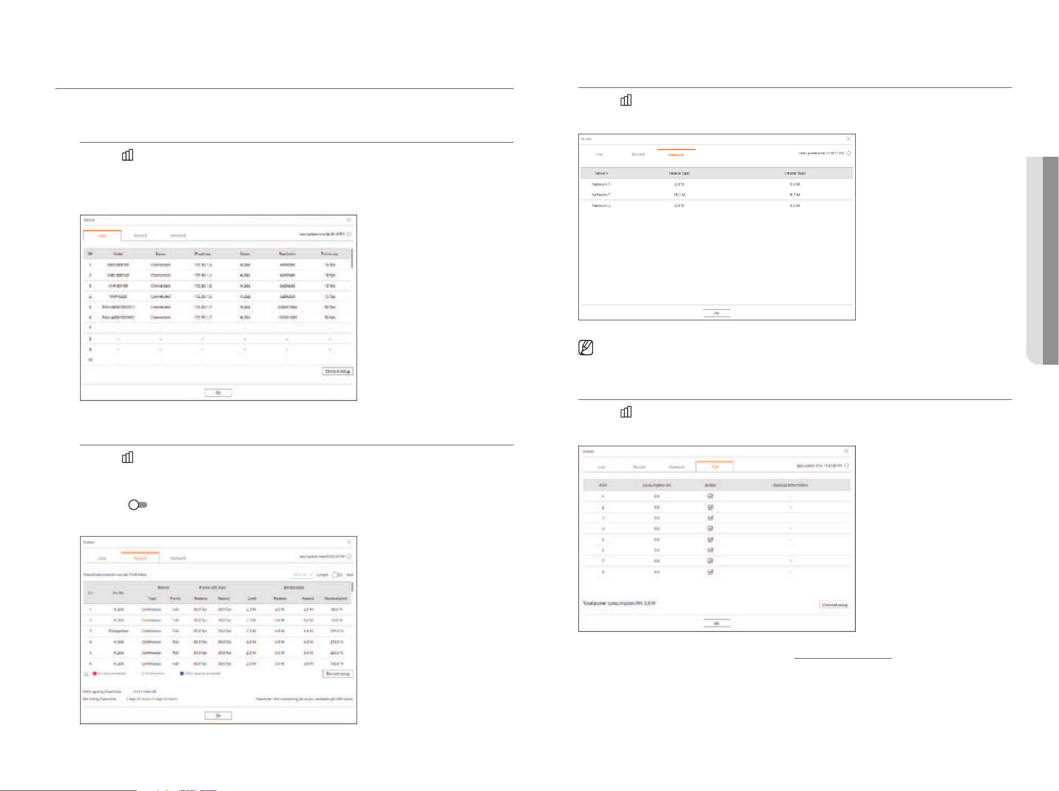
English _87
CheCking the aLL CaMera status
You can check the status of all cameras connected to the recorder.
Live status
Click the < > button. You can check the status and transmission information of the camera connected to each
channel.
■
To change the profile setup, click the <Camera setup> button. For details on how to set up the profile, refer to the "Setup > Setting the Camera >
Setting the Profiles” page in the Table of Contents.
record status
Click the <
> button, followed by the <record> tab.
You can check the profile, record type, frame rate (Input/Record), and bit rate (Limit/Input/Record) for each
channel.
■
Use <Current Max> to check the current recording status and maximum recording setting value.
■
To change the profile setup, click the <Record Setup> button.
network status
Click the <
> button, followed by the <network> tab.
You can check the status of network bandwidth currently being received/transmitted.
■
Each product supports a different number of network ports.
Poe status
Click the < > button and then click <Poe>.
You can check the current PoE status of each port.
■
This function is only available for products that support PoE. (Refer to the "Functions Supported by Model" page.)
• LiVe VieWer
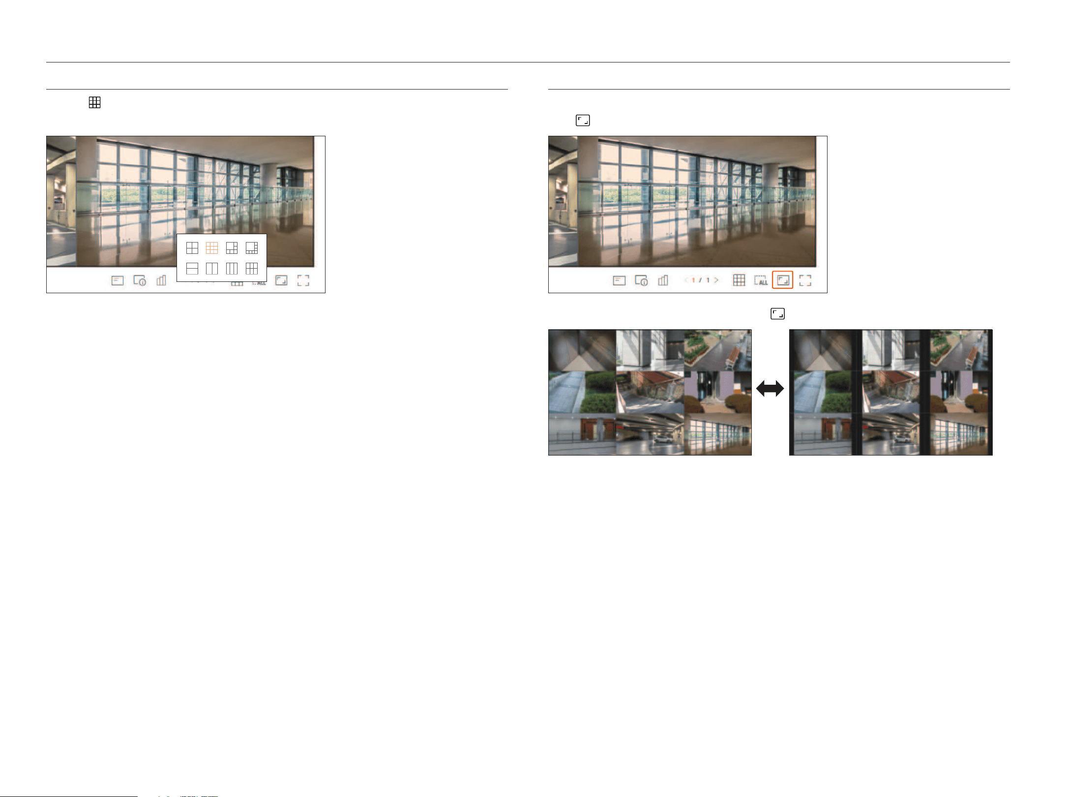
88_ live viewer
live viewer
Changing the Pattern oF sPLit sCreen
Click the <
> button and select the desired split screen.
The selected split screen is applied to the video window.
Changing oVeraLL ChanneL asPeCt ratio
Video screen ratio for all channels can be changed in live split screen mode.
Click <
> at the bottom of the screen. It changes to the actual proportion of the video.
If you want to go back to the previous screen ratio, click < > again.
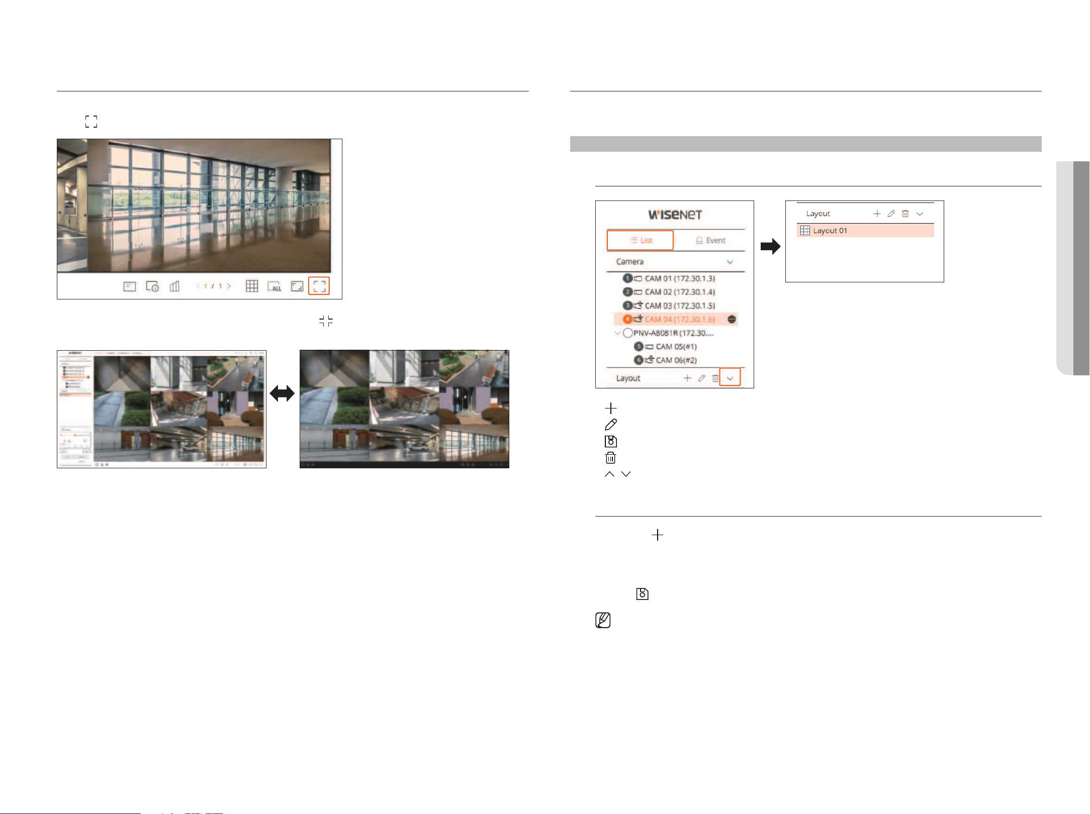
English _89
FuLL sCreen Mode
You can change to full screen mode, which has no top/bottom/left/right areas of the live screen.
Click <
> at the bottom of the screen.
To exit the full screen, press the esC key on the keyboard or click < > at the bottom of the full screen mode.
general mode Full screen mode
setting uP the LiVe Layout
This section outlines how to select a series of channels based on their purpose/accessibility and monitor them in a
single layout.
Live > List
Check Layout List
●
: Create a new layout.
●
: Change the channel or name of the layout.
●
: Save the changed layout.
●
: Delete the added layout.
●
/ : Open or close the layout list.
add Layout and set name
1. Click the <
> button.
2. Set the name of the layout.
3. Double-click a channel to display on the layout screen from the camera list.
4. Click <
> to save the set layout.
■
The default layout of the live viewer consists of a 4-split screen.
■
Each layout is saved separately by the user.
• LiVe VieWer
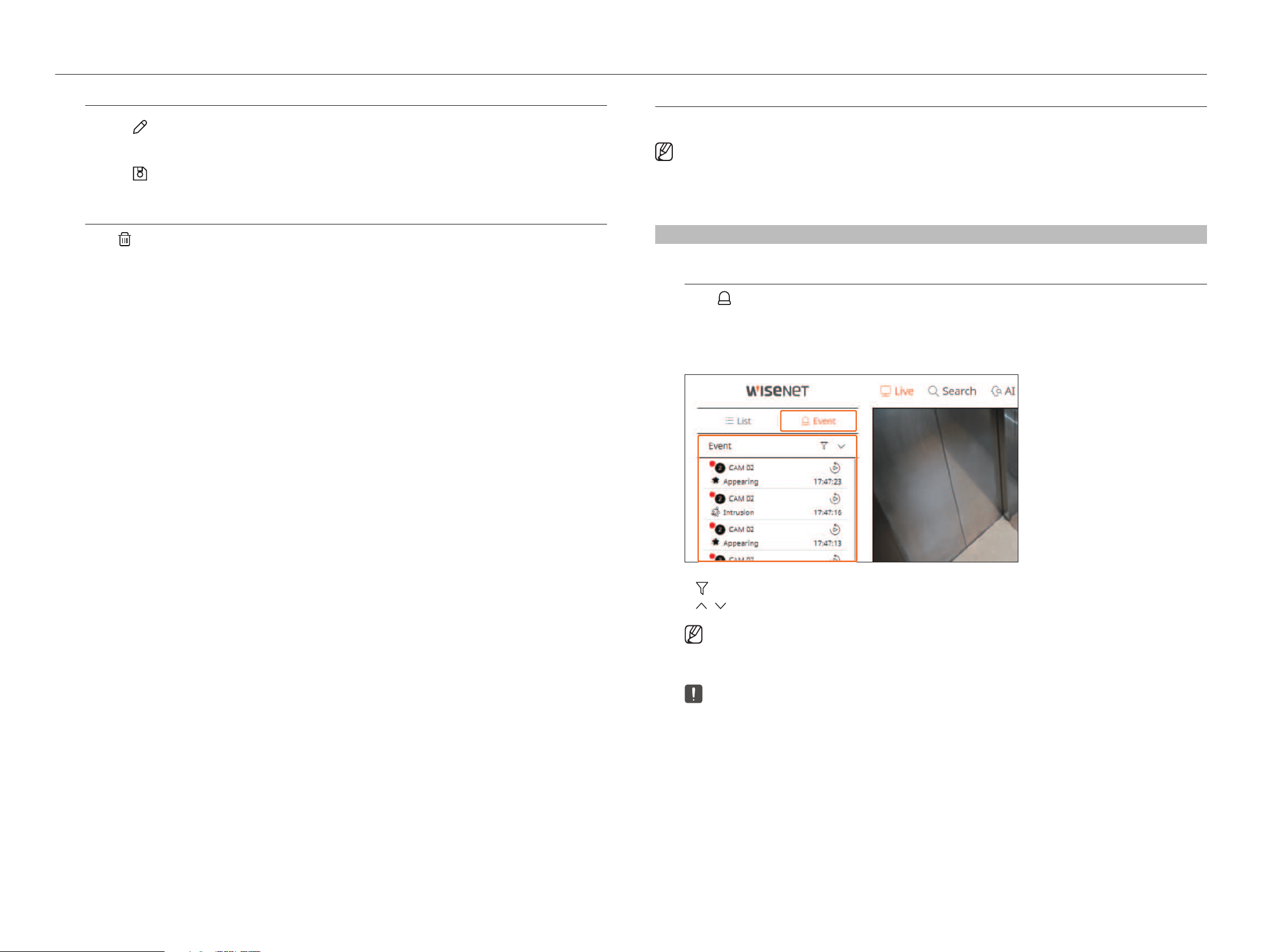
90_ live viewer
live viewer
Change of Layout Channel and name
1. Click <
> after selecting a layout.
2. Add or delete channels or rename layouts.
3. Click <
> to save the changed settings.
delete Layout
Click <
> after selecting the layout to delete.
reaL-tiMe eVent Monitoring
Real-time events that occurred on the camera can be checked in the live video window and event list.
■
AI events are only available for products that support AI.
■
AI events are displayed only after setting event rules. AI event search may have different settings and operation specifications depending on the recorder
or camera.
■
Live event monitoring can receive data on only one channel and data can be received only from the camera currently being monitored in live.
Live > event
Check event List
Click <
event> on the left side of the live screen to display the real-time event list.
■
When new events occur, the list of events will be updated accordingly.
■
The specified channels and events are displayed in the list according to the event rule setup.
For details, refer to the "Setup > Setting the Event > Event rule setup" page in the Table of Contents.
●
: Browses for the event by the desired condition.
●
/ : Open or close the event list.
■
When an alarm output occurs, if the event recording is set and the pre-event time and post-event time are set, the event recording is executed
before or after the event according to the set recording method. For more information about event recording settings, refer to the "Setup >
Setting the Recording > Record setup" page in the Table of Contents.
■
The video may be delayed depending on the network conditions.
■
The event output can be delayed as the transfer of the alarm event from the network camera takes time.
■
The Safari browser does not support this feature.
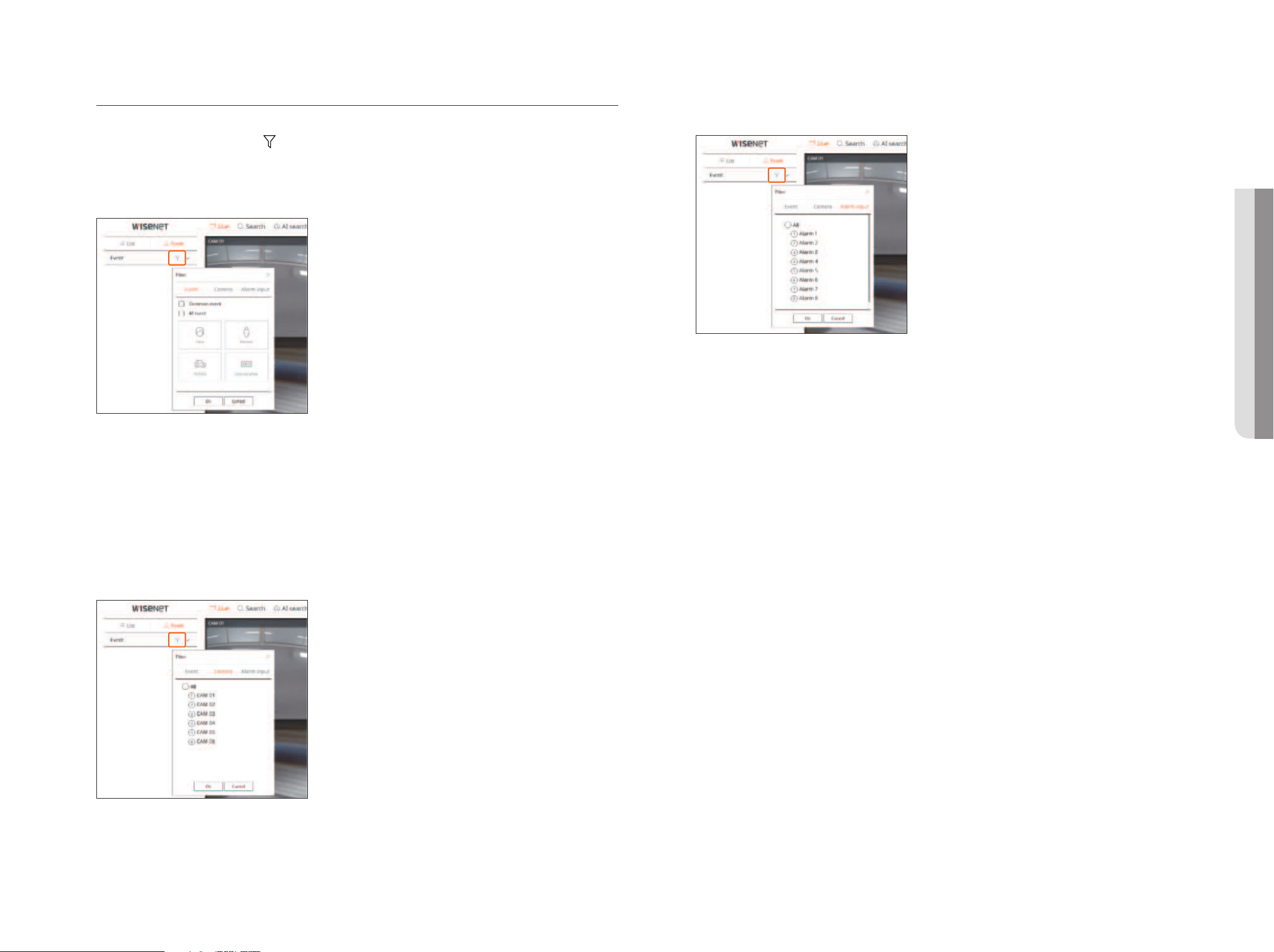
English _91
event search
You can search events by camera, alarm input (recorder), and event type.
To search for a specific event, click <
> to select the event type and camera to browse.
event filter
Displays only selected events in the event list.
●
Common event : Searches for event types that have occurred in general cameras such as motion detection and
IVA.
●
AI event : Searches for AI event types such as face, person, and vehicle.
■
AI events are only activated when an AI camera is connected.
■
AI events are displayed only after setting event rules. For details, refer to the "Setup > Setting the Event > Event rule setup" page in the Table of
Contents.
Camera filter
Displays events for the selected camera only.
alarm input filter
Displays the only events for the alarm input numbers of the selected recorder.
• LiVe VieWer
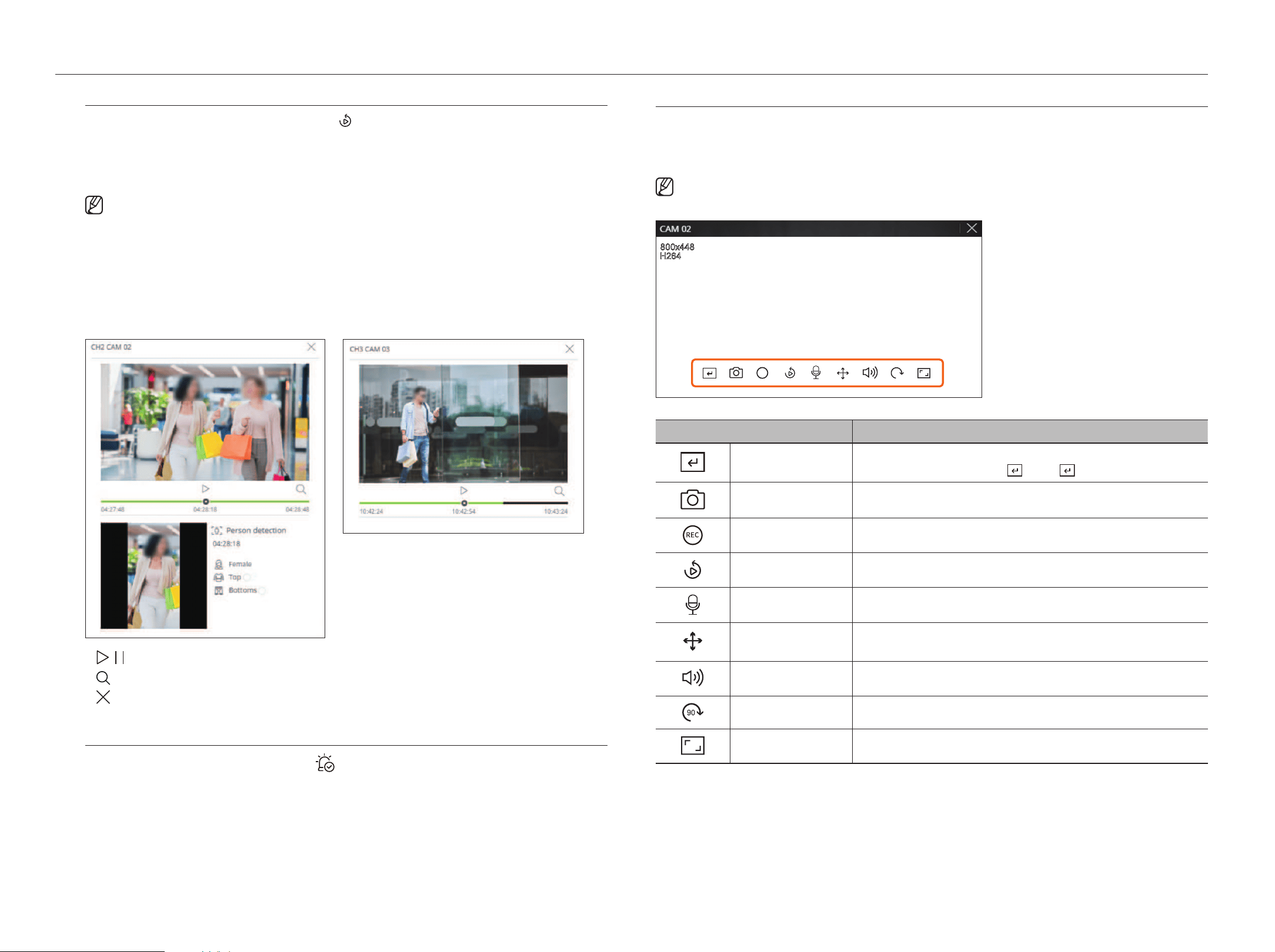
92_ live viewer
live viewer
event instant Viewer
Select an event to check from the event list, and click <
> to play the recorded video at the time the event
occurred.
■
Instant viewer can play an event video for 1 minute.
■
For AI events, the best shot and details of the event that occurred are displayed.
■
AI event recognition may have different settings and operation specifications depending on the recorder model or camera.
■
To see AI events, set any of the following options as necessary : See the relevant page for detailed setup method.
– Setup > Event > Event setup > Object
– Setup > Event > Event setup > Mask
– Setup > Event > Event setup > IVA
– Setup > Event > Event rule setup
Common eventai event
●
/ : The video is played/paused.
●
: Go to the search menu screen.
●
: Instant Viewer playback ends.
stop alarm output
When an event occurs, an alarm can occur. Click <
> at the bottom of the screen to stop the alarm output if
necessary.
For details, refer to the "setup > setting the event > event rule setup" page in the Table of Contents.
LiVe sCreen Menu
After selecting the desired channel on the split mode, roll the mouse cursor over the screen to see the live screen menu.
The live screen menu appears differently depending on the recorder operation status or the type of the registered
camera.
■
Each function may be restricted depending on the type of camera and the user's authority.
REC
90
Menu Description
Manual trigger
If the event action for <Manual trigger> is set for the selected channel, the event rule name is
displayed when you hover the mouse over <
>. Click < > to activate the set event.
Capture You can take a screenshot of the selected channel.
PC REC Images can be saved on a PC.
Instant viewer During monitoring, you can rewind 1 minute before playback.
Microphone Turns the microphone on or off on your PC.
PTZ control
If the network camera connected to the selected channel supports the PTZ function, it changes to the
PTZ control mode.
Audio Turns the audio on or off when the audio is connected.
Image rotation Rotates the video to display.
Channel aspect ratio Shows the video in actual proportions.
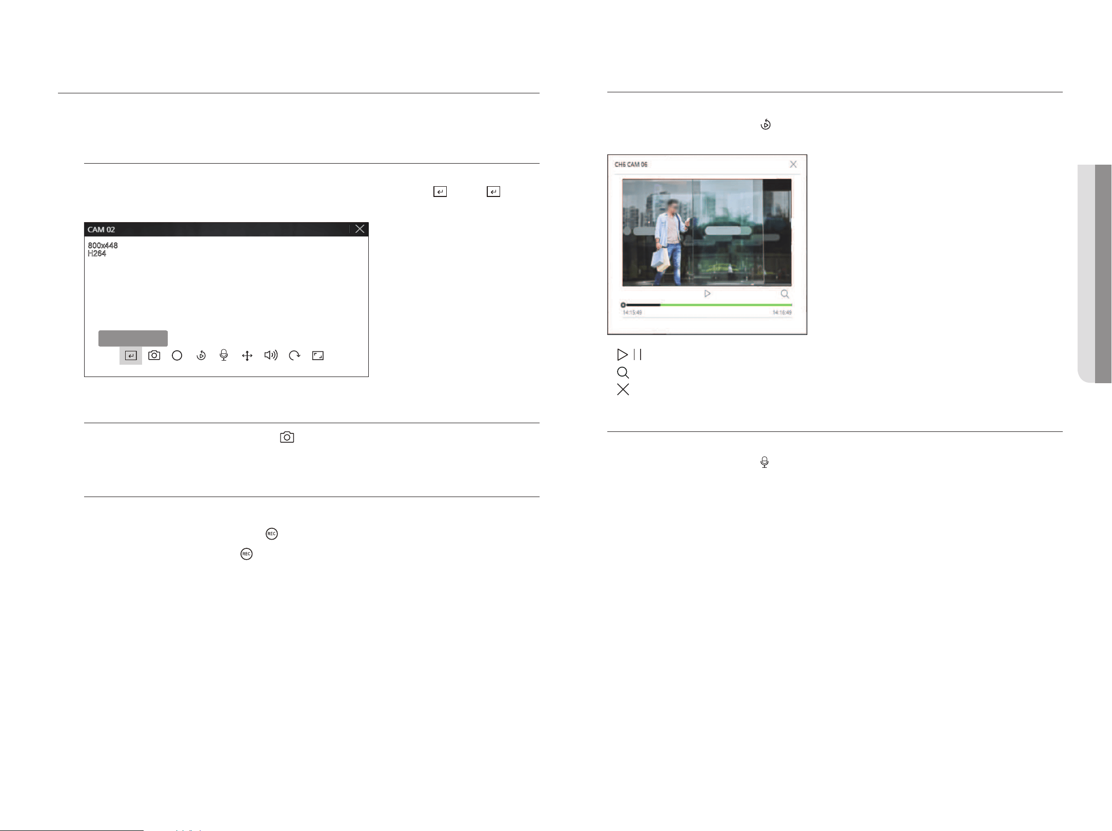
English _93
CaMera Video ControL
By using the function icon in the video window, you can easily enable functions such as screenshot, video rotation, and
PTZ control.
Manual trigger
If the event action for <Manual trigger> is set for the selected channel in the "setup > event > event rule
setup" menu, the event rule name will be displayed when you hover the mouse over <
>. Click <
> to
activate the set event.
REC
90
Manual trigger 1
Capture
Select a channel to capture video and click the <
> button.
The captured image is saved as .png file in the download folder.
PC recording
You can record video on your PC while monitoring.
1. Select the desired channel and click the <
> button to start PC recording.
2. To end the PC recording, click the <
> button.
The recording ends, and the recorded video is saved as .avi file in the download folder.
instant Viewer
During monitoring, you can rewind 1 minute before playback.
Select the desired channel and click <
>.
The Instant Viewer screen appears.
●
/ : The video is played/paused.
●
: Moves to the playback screen.
●
: Instant Viewer playback ends.
Microphone output
You can turn the microphone of the selected channel on or off in the live screen.
Select the desired channel and click <
>.
• LiVe VieWer
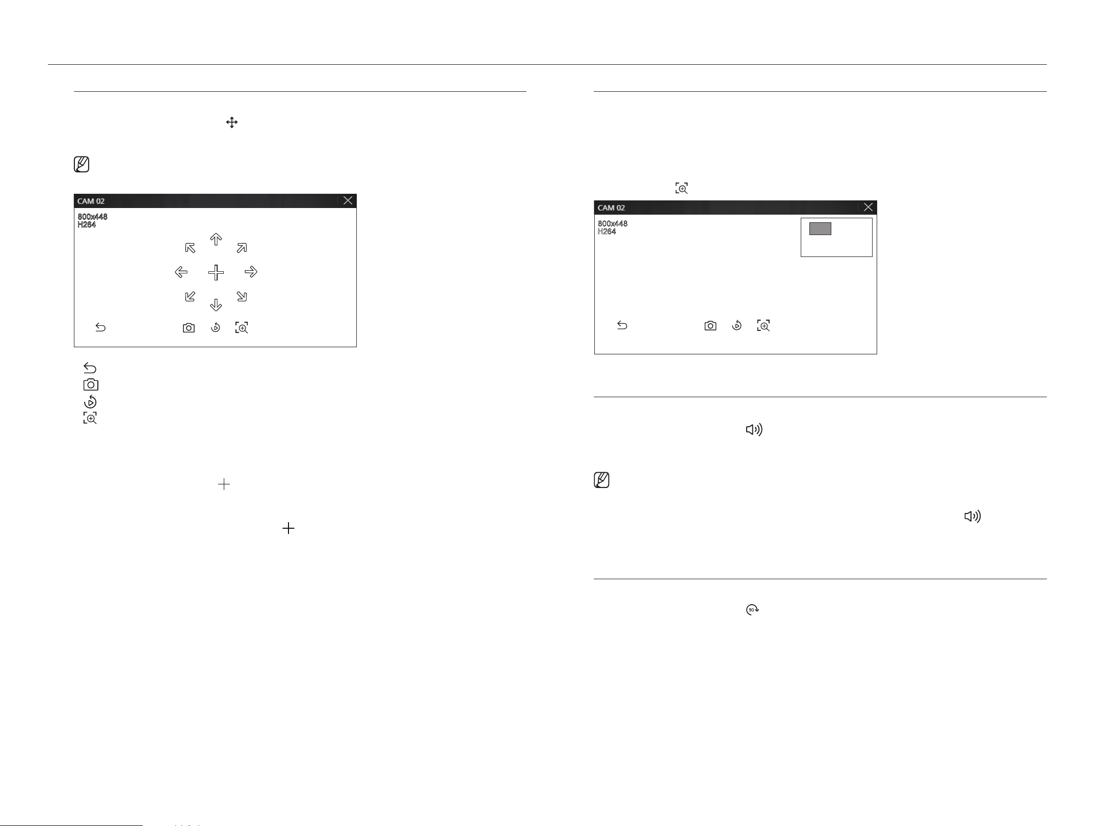
94_ live viewer
live viewer
Ptz Mode
You can run PTZ control of the selected channel.
Select the desired channel and click <
>.
Enters the PTZ control mode.
■
Depending on the camera, the PTZ control function and speed may be different.
●
: The PTZ mode is closed.
●
: Captures video of the current state.
●
: Go to the instant viewer.
●
: Click the Digital zoom icon and use the mouse wheel to zoom in or out on the video.
Digital zoom ends when the video screen is reduced to the original size.
adjusting the Camera direction
When you rolls over the mouse to <
>, the 8-way key appears, and when the mouse leaves the area of the
direction key, the direction key disappears. You can fine-tune the camera direction by clicking the 8-direction key
once. Keep clicking the arrow keys to move in the desired direction and release the mouse to stop.
To quickly adjust the direction of the camera, click <
> and drag. The screen moves quickly in the desired
direction. You can adjust the screen movement speed according to the drag distance.
zoom in
You can zoom in or out using the mouse wheel.
If you scroll up using the mouse wheel, the selected video screen is enlarged by 10%, and a thumbnail window is
displayed.
■
Scrolling up/down using the mouse wheel will zoom in/out the video screen by 10%.
■
Digital zoom ends when the video screen is reduced to the original size.
■
In PTZ mode, click the < > button to run digital zoom.
audio
You can turn the sound on/off corresponding to the channel in Live mode.
Select the desired channel and click <
>.
Audio output can only be turned on in one channel. The audio output of other channels will be automatically
turned off.
■
If you have configured the audio output settings properly but the audio or voice is not output, check if the connected network camera supports
the sound signal and if you have configured the sound settings as appropriate.
The sound icon can be displayed if the sound signal fails to output from noise.
■
Only the channel where <Audio> is set to <On> in “Setup > Camera > Channel setup” displays the audio icon ( ) in Live mode that
you can use to turn the sound on/off.
image rotation
You can rotate the live video screen.
Select the desired channel and click <
>.
Each click of the button will rotate the video 90 degrees clockwise.
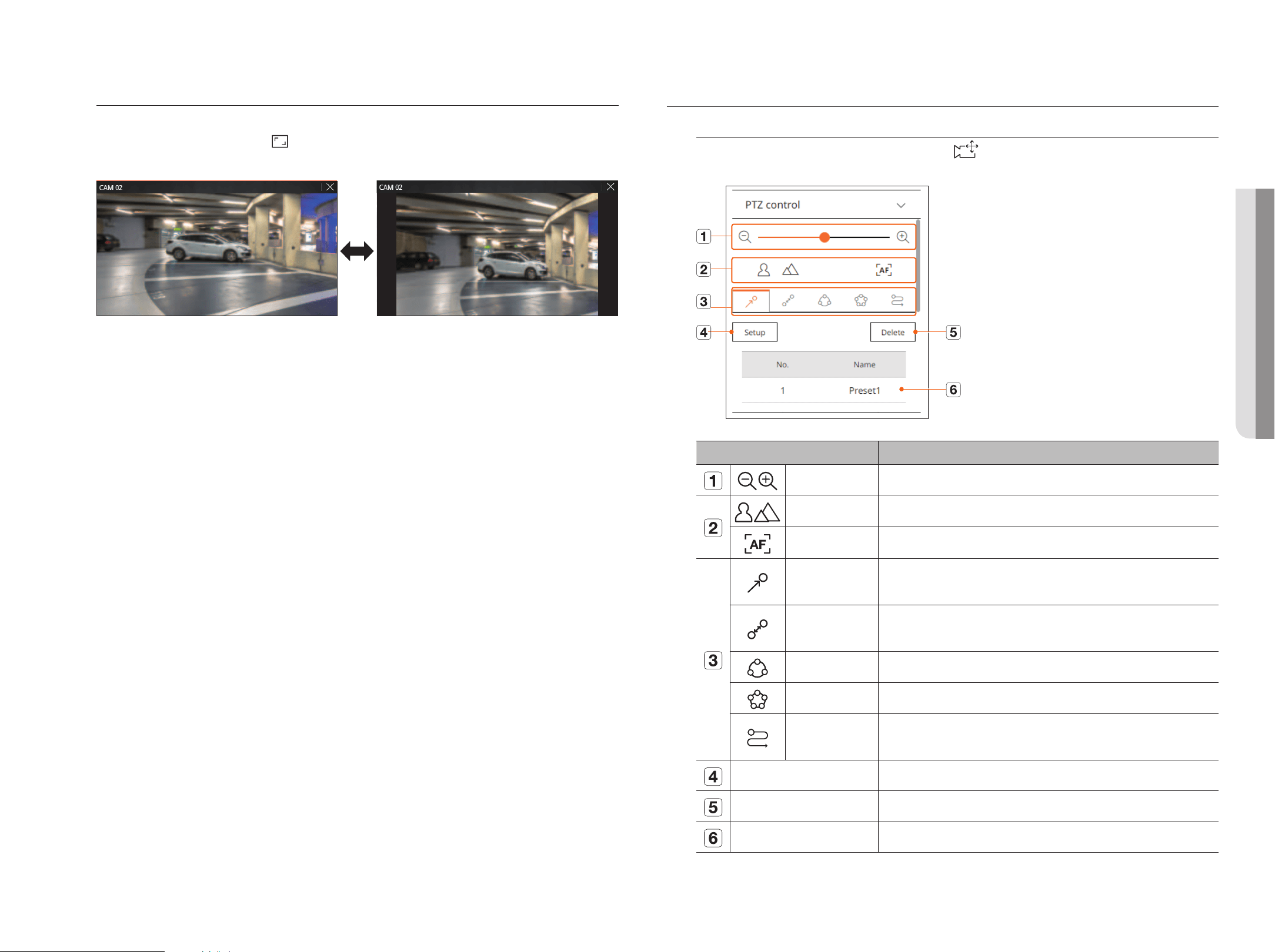
English _95
Channel aspect ratio
You can change the aspect ratio of each channel.
Select the desired channel and click <
>.
It changes to the actual proportion of the video.
Ptz ControL
Ptz Control Menu
If the connected network camera is a PTZ camera, the <
> icon is displayed in the camera list. When the
camera channel is selected, you can control the PTZ.
Name Description
Zoom out/Zoom in Activate the Zoom operation of the PTZ camera.
Near/Far You can adjust the focus manually.
Auto focus You can adjust the focus automatically.
Preset
Set the preset position to move the camera, and then select the desired preset to move to the set
position.
Swing
Swing is a monitoring function that moves between two preset points and enables you to trace the
motion.
Group The group function enables you to group various presets before calling them in sequence.
Tour Monitor all the groups created by a user in turn.
Trace
Tracking remembers the trace of movements that you instructed and reproduces it for your
reference.
Set The preset you set is saved and displayed in the list.
Delete Deletes the selected preset list.
Preset List Shows a list of saved presets.
• LiVe VieWer
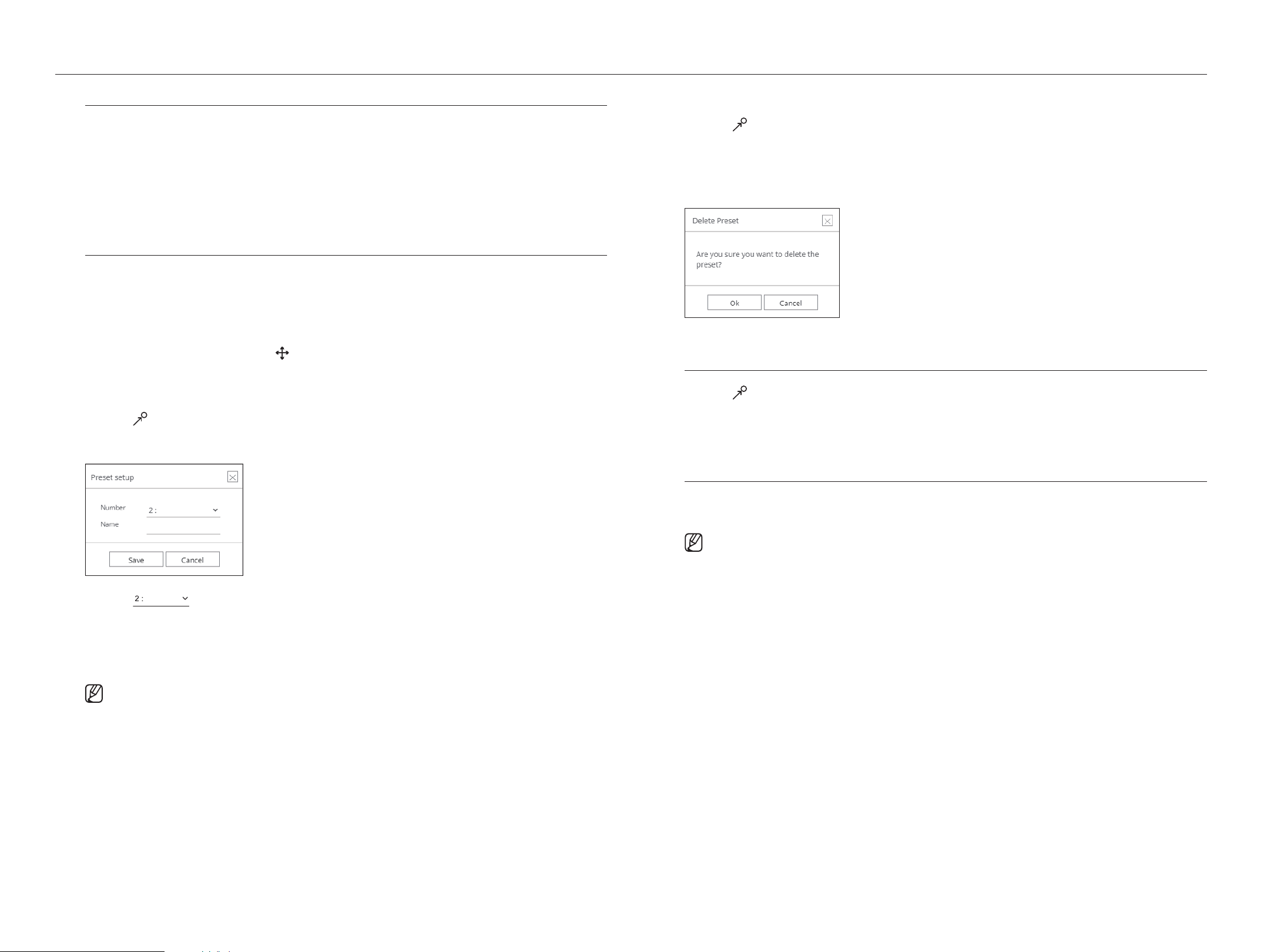
96_ live viewer
live viewer
using digital Ptz (d-Ptz) function
1. Register a camera that supports the D-PTZ profile.
■
In cameras that support the D-PTZ profile, you can use the D-PTZ function.
2. Both cameras that support general PTZ and cameras that support D-PTZ can control the live image using
some of the <Ptz control> function menus.
■
For more information about the supported functions, please refer to the camera manual.
Preset
Preset is a set of saved data specifying the locations of a PTZ camera. A single PTZ camera can save up to 300
locations.
to add a preset
1. Select the desired channel and click <
>.
■
The PTZ control screen appears.
2. Use the arrow keys to adjust the camera to the point.
3. Click <
>.
4. If you click <set>, the <Preset setup> window will appear.
5. Click < > to select the Preset Order to set.
6. Enter the Preset name.
7. Click <save>.
The preset setting will be saved.
■
If you replace a camera that saves your preset settings with a different one, you must configure the preset settings again.
to delete a registered preset
1. Click <
>.
2. Select the preset to delete, and click <delete>.
3. <delete preset> window will appear, and click <ok>.
The selected preset will be deleted.
running Preset
1. Click <
>.
2. Double-click the preset you want to run from the list.
The camera lens moves to the set position.
running swing (auto pan), group (scan), tour, or trace (pattern)
The running method of each function is the same as the preset operation method. For details on how to use it,
refer to the camera's user manual.
■
Depending on the camera's capabilities, only some features may be available.
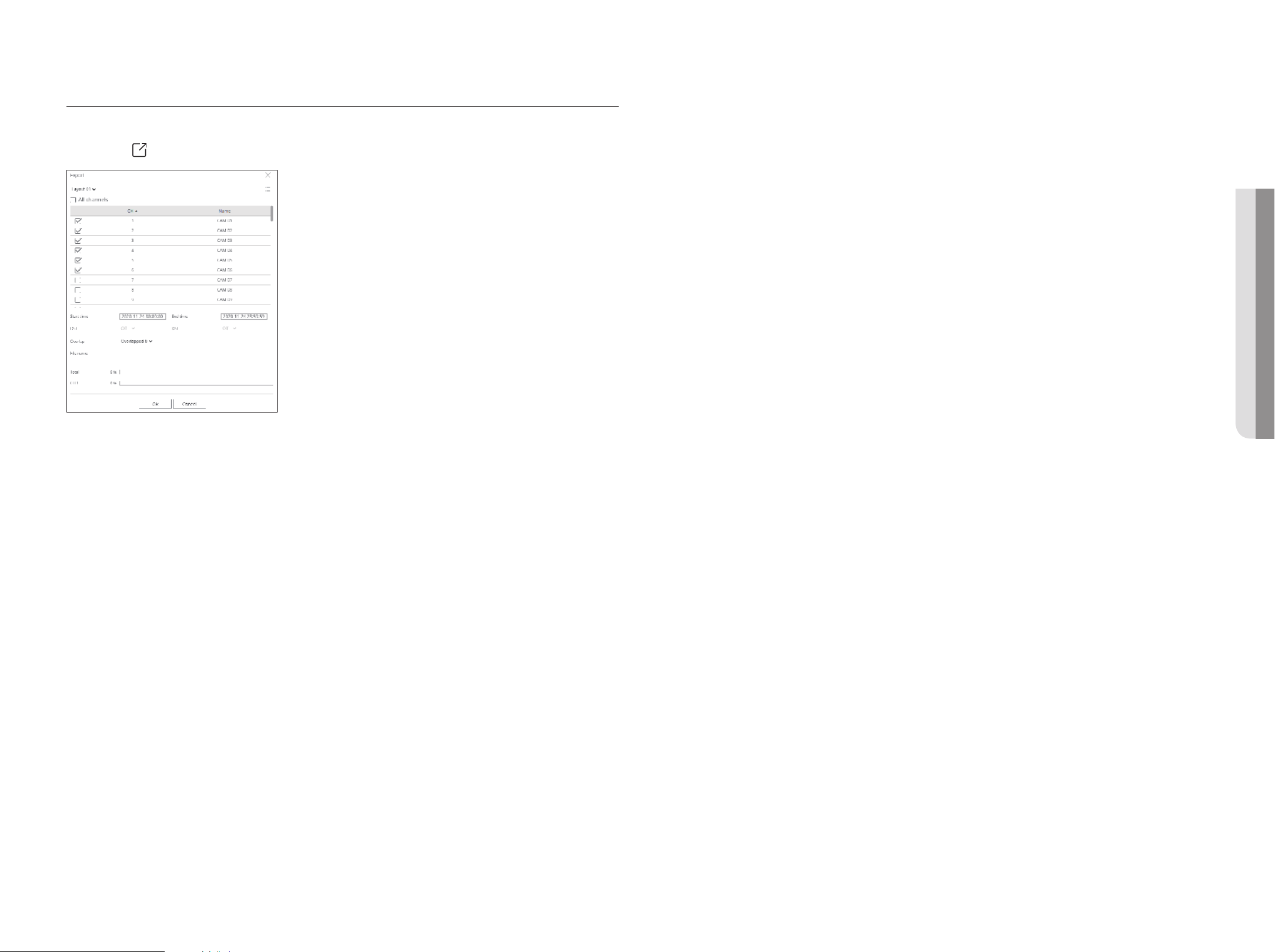
English _97
exPorting Video
You can export the recorded video by manually inputting the desired channel, date, and time.
1. Click the <
> button.
2. Select a layout to export and select the desired channel.
3. Set the start date/time and end date/time.
■
After setting whether to enable DST or not, select the overlap. It will be displayed when there is overlapped data in one channel by changing the time or time
zone at the selected time.
4. Enter a file name to save, and then click the <ok> button.
5. When the export is complete, a confirmation window appears.
■
The exported video is saved as .avi file in the download folder.
• LiVe VieWer
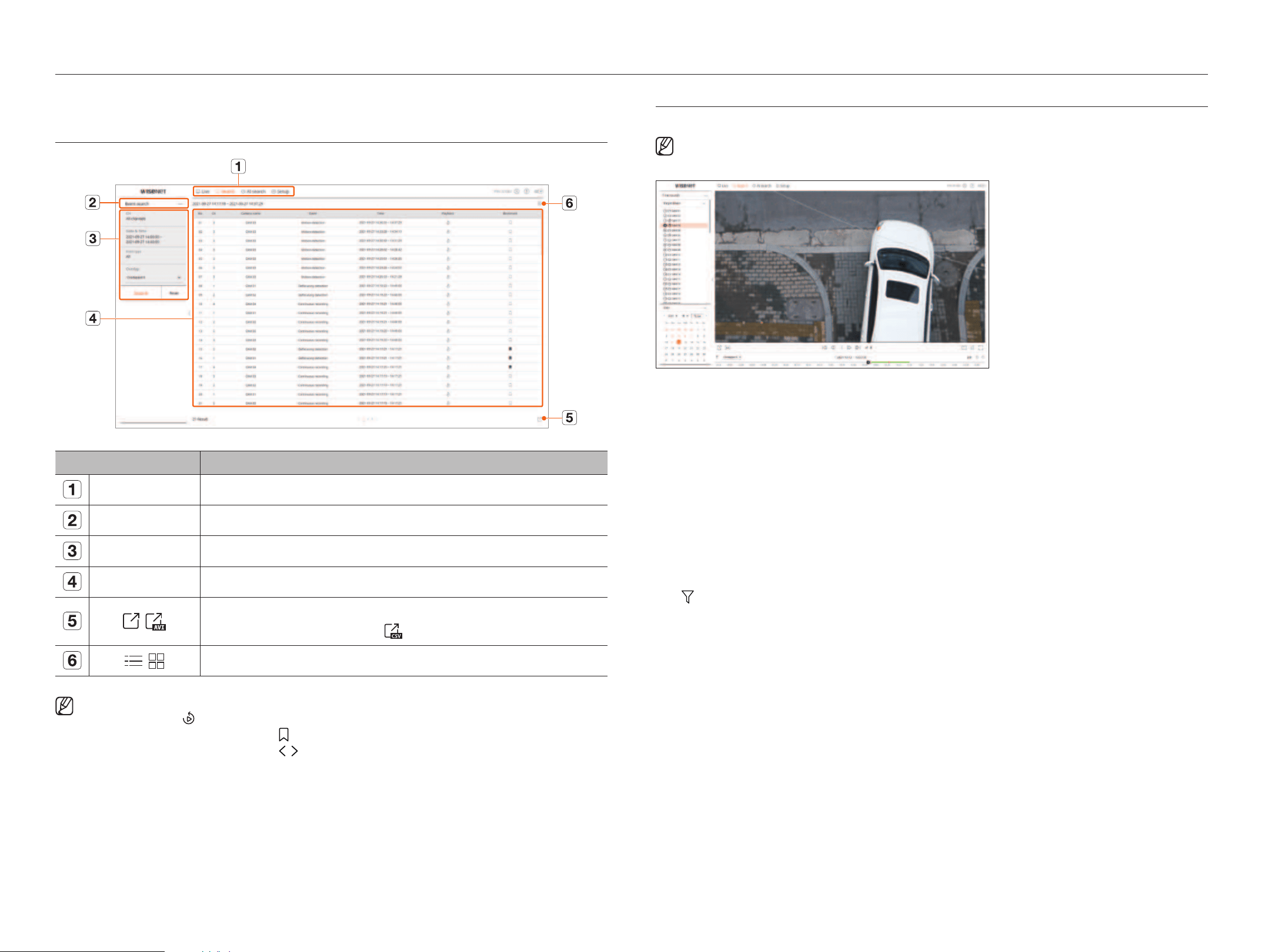
98_ search viewer
You can search and play the recorded video stored in the recorder by connecting the recorder remotely.
sCreen Layout oF the searCh VieWer
Name Description
Menu Click each menu to go to the corresponding menu screen.
Search menu tab Click the menu tab to display the detailed search menu. Click Search menu to go to the corresponding Search screen.
Search conditions You can set various search conditions, such as date/time/event.
Search results Displays search results.
/
Exports search results to an .avi file.
■
In the <Text search> results, you can also click < > to export to a .csv file.
/
Displays the search results as a list or thumbnail.
■
Click <Reset> to initialize the search conditions and results.
■
When you click Playback ( ), the video will be played in an instant viewer.
■
You can specify a bookmark by clicking the bookmark ( ) in the search results list. You can check the specified video in the bookmark search menu.
■
If the search results are in multiple pages, you can click
/
to go to the previous/next page. Or, you can click the current page number and enter the
page you want to move to.
tiMe searCh
You can search the recorded data by the desired date and time conditions.
■
The time displayed will be based on the time zone and daylight saving time (DST) applied time zone, so it may be displayed differently depending on
whether the data time zone recorded at the same time and daylight saving time (DST) is applied.
1. Select <time search> in the <search> menu.
2. Select a channel to search.
3. Select the year and month to search.
Dates with data will be shown in orange and current dates will be shown in orange circles.
4. Select a date to search from the calendar.
The recorded video for that day will be played from the beginning, and the data will be displayed in the timeline.
●
Click <to da y> to search for today's date. Today’s date will be selected.
●
The displayed color differs depending on the type of recording data.
– Light green : Normal recording video
– Red : Event recording video
●
: You can filter the event items to view the time line.
●
Overlapped : You may check the timeline by setting the overlapping section caused by time change.
search viewer
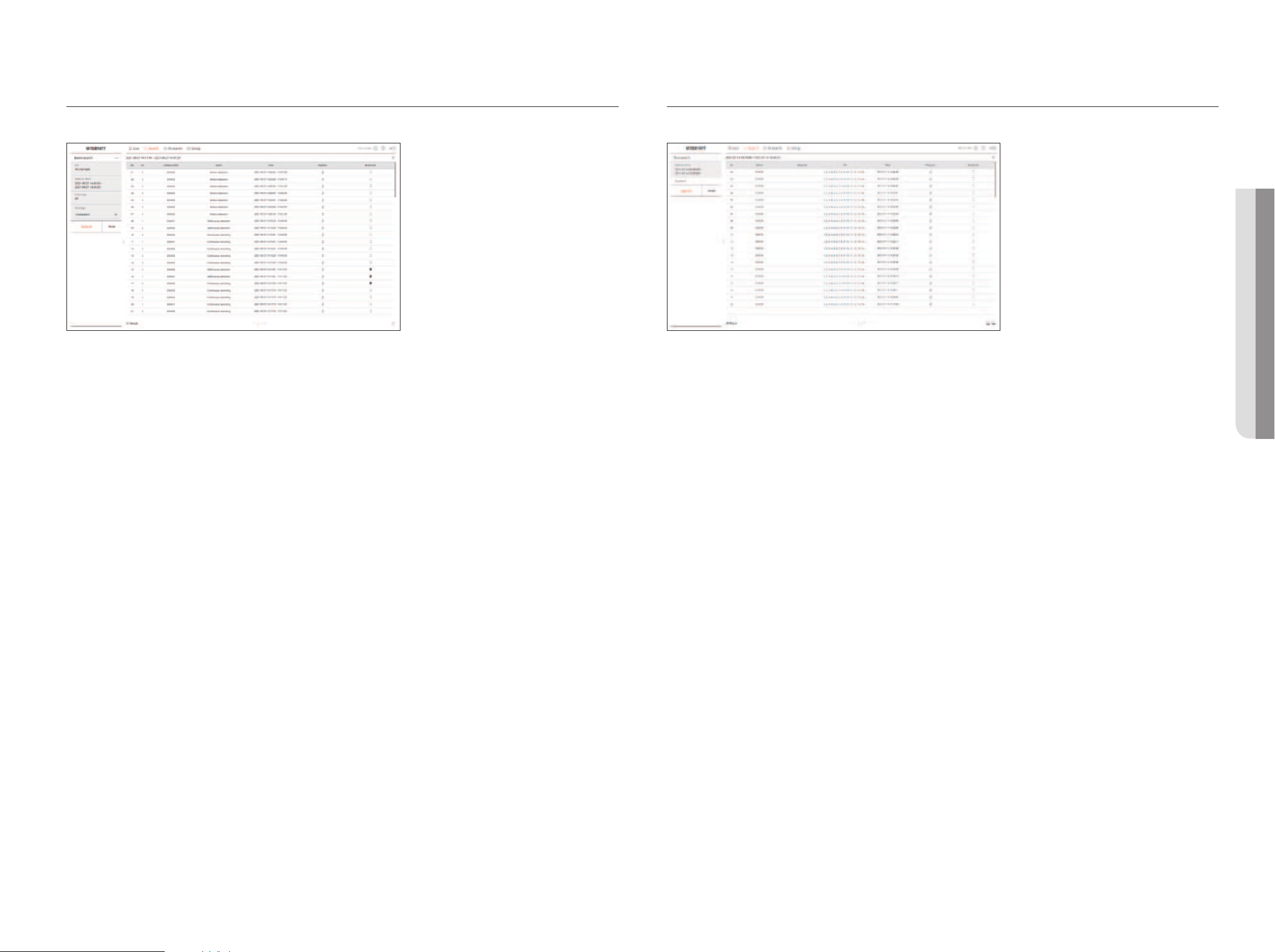
English _99
eVent searCh
You can search for various events by channel.
1. Select <event search> in the <search> menu.
2. Select a channel to search.
3. Select a date and time to search.
4. Select an event type.
●
Event type options may vary depending on the camera model.
5. Select the overlap.
●
It will be displayed when there is overlapped data in one channel by changing the time or time zone at the
selected time.
6. Click the <search> button.
The search results list will be displayed.
■
To stop the search, click <Stop> in the search pop-up window. You can check the search results up until now.
●
CH : Displays the channel where the event occurred.
●
Camera name : Displays the camera name.
●
Event : Displays the event type of the recorded video.
●
Time : Displays the start time and end time of the recorded video.
●
Playback : Plays the recorded video with an instant viewer.
●
Bookmark : Specifies a bookmark for the recorded video.
text searCh
You can search the data input to the POS device connected to the recorder.
1. Select < text search> in the <search> menu.
2. Select the date and time to search.
3. Set the event keywords and search condition.
●
Event keyword : You can search for text with preset event keywords. For details, refer to the "setup > setting the
device > tex t " page in the Table of Contents.
●
Text search keyword : Enter the text you want to search.
●
Match with case sensitivity : Searches are case-sensitive when checking.
●
Match whole words : Searches for data that exactly matches the characters entered.
4. Select the overlap.
●
It will be displayed when there is overlapped data in one channel by changing the time or time zone at the
selected time.
5. Click the <search> button.
The search results list will be displayed.
■
To stop the search, click <Stop> in the search pop-up window. You can check the search results up until now.
●
Device: Displays the name of the POS device connected to the recorder.
●
Keyword: Displays the searched text.
●
CH : Displays the channel where the event occurred.
●
Time: Displays the start time of the recorded video.
●
Playback : Plays the recorded video with an instant viewer.
●
Bookmark : Specifies a bookmark for the recorded video.
• searCh VieWer
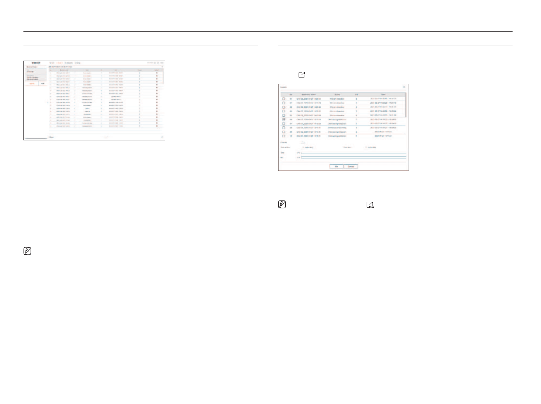
100_ search viewer
search viewer
bookMark searCh
You can search for bookmarked data.
1. Select <bookmark search> in the <search> menu.
2. Select a channel to search.
3. Select the date and time to search.
4. Click the <search> button.
The search results list will be displayed.
●
Bookmark name: Displays the bookmark name you set.
●
Event: Displays the event type of the recorded video.
●
CH: Displays the recorded channel.
●
Time: Displays the start time and end time of the recorded video.
●
Playback : Plays the recorded video with an instant viewer.
●
Bookmark: Displays whether bookmarks are specified.
■
Bookmarked images will be stored without being overwritten during repeated recording. However, when the automatic deletion is set, it will be deleted
according to the set period.
■
When the bookmark is released, the video will not be saved. If necessary, before releasing the bookmark, export the video.
■
Up to 100 bookmarks can be specified.
searCh resuLts exPort
Search results of events, texts and bookmarks can be exported to a file.
example) bookmark search result export
1. Click <
> in the search results list.
2. Select the desired list and click <ok>.
■
The exported video is saved as .avi file in the download folder.
■
In the <Text search> results, you can also click < > to export to a .csv file.
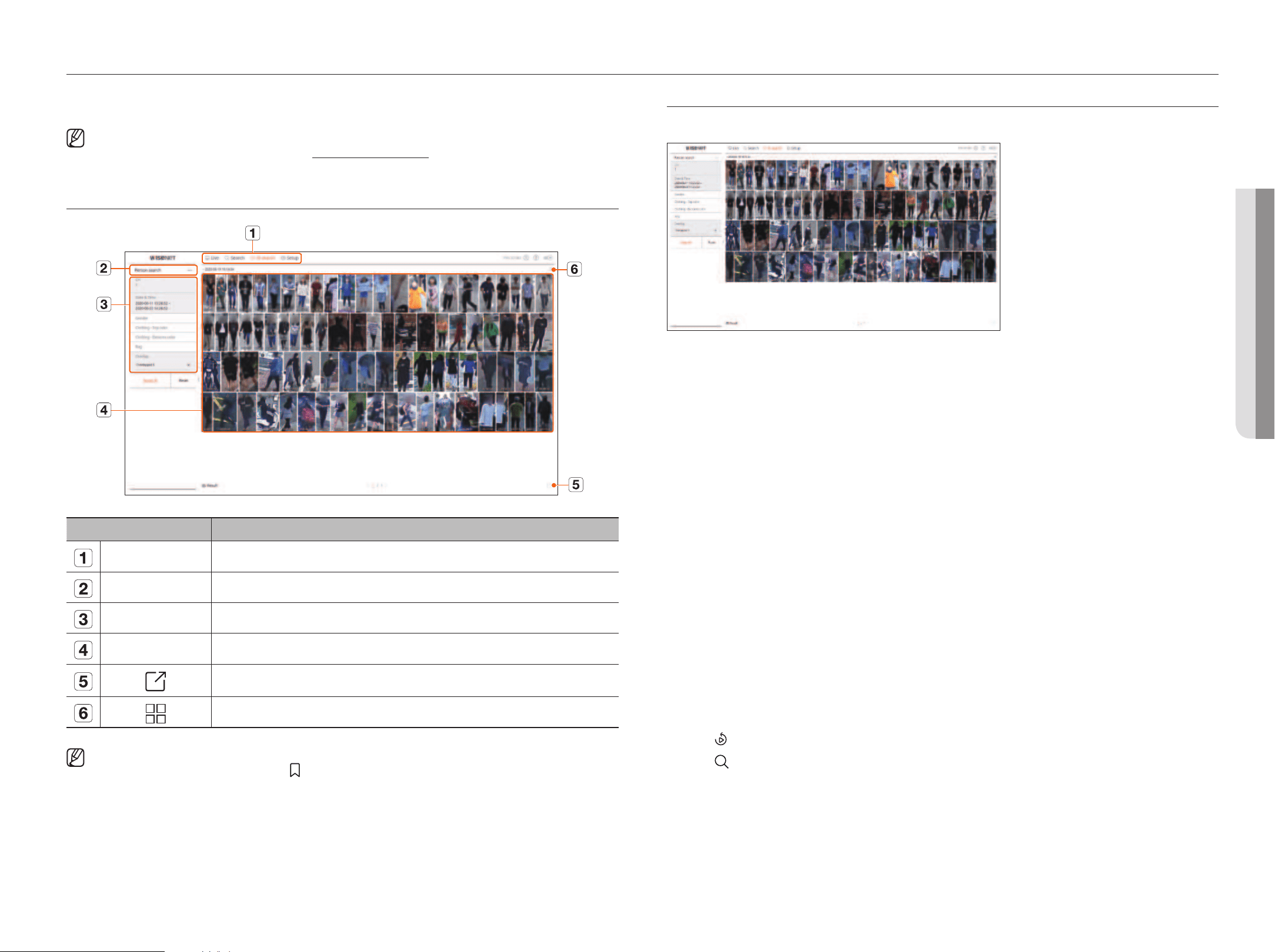
English _101
AI search viewer
If there is AI data recorded by the camera, you can search for images in various conditions such as people, faces, and
vehicles.
■
This function is not supported in some models.
■
For products that support the AI search function, refer to the "Functions Supported by Model" page.
sCreen Layout oF the ai searCh VieWer
Name Description
Menu Click each menu to go to the corresponding menu screen.
Search menu tab Click the menu tab to display the detailed search menu. Click Search menu to go to the corresponding Search screen.
Search conditions You can set various search conditions, such as date/time/gender.
Search results Displays search results
Exports search results to a file.
Displays the search results as a list or thumbnail.
■
Click <Reset> to initialize the search conditions and results.
■
You can specify a bookmark by clicking the bookmark ( ) in the search results list. You can check the specified video in the bookmark search menu.
Person searCh
In the recorded data, you can search for a person by any condition you want, such as gender, top/bottom color.
1. Select <Person search> in the <ai search> menu.
2. Select a channel to search.
3. Select the date and time to search.
4. Select a detailed search option.
●
Person search options : gender, Clothing-top color, Clothing-bottoms color, bag
■
Click the option to display the option selection window. Select the desired search option.
■
If no details are set, all conditions will be selected and searched.
5. Select the overlap.
It will be displayed when there is overlapped data in one channel by changing the time or time zone at the selected
time.
6. Click the <search> button.
The search results list will be displayed.
■
To stop the search, click <Stop> in the search pop-up window. You can check the search results up until now.
●
CH : Displays the recorded channel.
●
Camera name : Displays the camera name.
●
Attribute : Displays the recognized search result attributes.
●
Time : Displays the start time of the recorded video.
●
Playback : Plays the recorded video with an instant viewer.
●
Bookmark : Specifies a bookmark to the recorded video.
7. Click <
> in the search list to display the instant viewer.
8. Click <
> to go to the playback screen.
• ai searCh VieWer
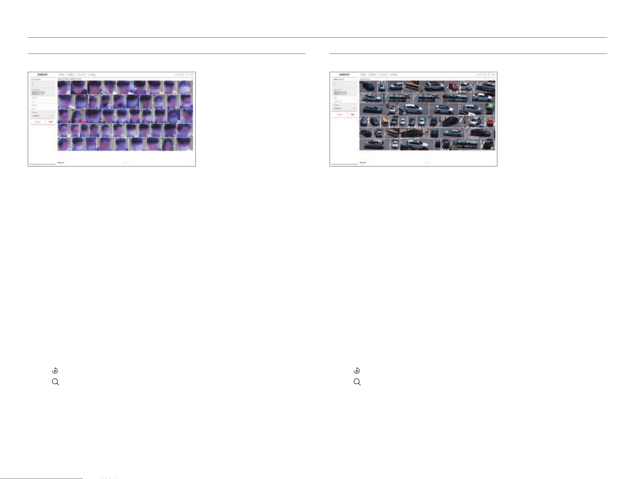
102_ AI search viewer
AI search viewer
FaCe searCh
From the recorded data, you can search faces according to your desired conditions such as gender and age.
1. Select <Face search> in the <ai search> menu.
2. Select a channel to search.
3. Select the date and time to search.
4. Select a detailed search option.
●
Face search options : gender, age, glasses, Mask
■
Click the option to display the option selection window. Select the desired search option.
■
If no details are set, all conditions will be selected and searched.
5. Select the overlap.
It will be displayed when there is overlapped data in one channel by changing the time or time zone at the selected
time.
6. Click the <search> button.
The search results list will be displayed.
■
To stop the search, click <Stop> in the search pop-up window. You can check the search results up until now.
●
CH : Displays the recorded channel.
●
Camera name : Displays the camera name.
●
Attribute : Displays the recognized search result attributes.
●
Time : Displays the start time of the recorded video.
●
Playback : Plays the recorded video with an instant viewer.
●
Bookmark : Specifies a bookmark to the recorded video.
7. Click <
> in the search list to display the instant viewer.
8. Click <
> to go to the playback screen.
VehiCLe searCh
You can search the vehicle by setting the vehicle type and color conditions from the recorded data.
1. Select <Vehicle search> in the <ai search>menu.
2. Select a channel to search.
3. Select the date and time to search.
4. Select a detailed search option.
●
Vehicle search options : type, Vehicle color
■
Click the option to display the option selection window. Select the desired search option.
■
If no details are set, all conditions will be selected and searched.
5. Select the overlap.
It will be displayed when there is overlapped data in one channel by changing the time or time zone at the selected
time.
6. Click the <search> button.
The search results list will be displayed.
■
To stop the search, click <Stop> in the search pop-up window. You can check the search results up until now.
●
CH : Displays the recorded channel.
●
Camera name : Displays the camera name.
●
Attribute : Displays the recognized search result attributes.
●
Time : Displays the start time of the recorded video.
●
Playback : Plays the recorded video with an instant viewer.
●
Bookmark : Specifies a bookmark to the recorded video.
7. Click <
> in the search list to display the instant viewer.
8. Click <
> to go to the playback screen.
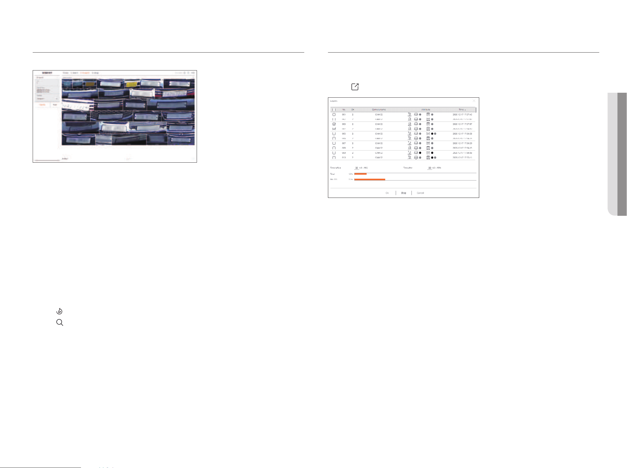
English _103
LP searCh
You can search for vehicle license plates from the recorded data.
1. Select <LP search> in the <ai search> menu.
2. Select a channel to search.
3. Select the date and time to search.
4. Select the overlap.
It will be displayed when there is overlapped data in one channel by changing the time or time zone at the selected
time.
5. Click the <search> button.
The search results list will be displayed.
■
To stop the search, click <Stop> in the search pop-up window. You can check the search results up until now.
●
CH : Displays the recorded channel.
●
Camera name : Displays the camera name.
●
Time : Displays the start time of the recorded video.
●
Playback : Plays the recorded video with an instant viewer.
●
Bookmark : Specifies a bookmark to the recorded video.
6. Click <
> in the search list to display the instant viewer.
7. Click <
> to go to the playback screen.
searCh resuLts exPort
Search results such as people, faces, and vehicles can be exported to a file.
example) Person search results export
1. Click <
> in the search results list.
2. Select the desired list and click <ok>.
■
The exported video is saved as .avi file in the download folder.
• ai searCh VieWer
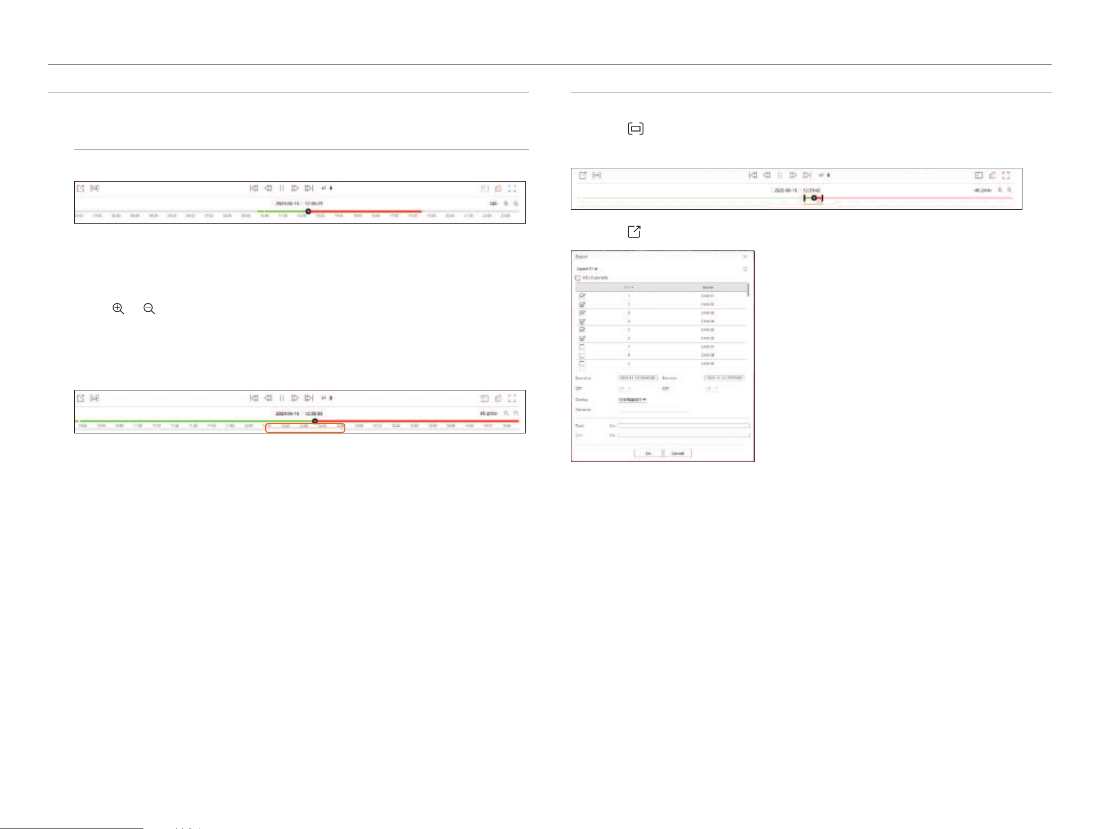
104_ play
PLay searCh resuLts
You can play the recorded data and export the video you want during playback.
to adjust the time Line
You can move the playback position and zoom the time line in and out.
●
Click the desired play position in the time line.
The playback start position will be moved.
■
Click the start point on the left side of the time line to move the playback position to the start point of the first video.
■
Place your mouse over the time line to see the corresponding thumbnail of the recorded video.
●
Click <
>, < > to zoom in or out the time display magnification. When the time line is enlarged, a scroll
bar will appear at the bottom.
■
You can use the mouse wheel over the time line to zoom in or out on the time scale.
■
The time line magnification of the time line will be displayed at the top right of the time line.
●
To see the time line before or after zooming in, zoom in and drag the time line left or right.
exPort Video by seCtion setuP
You can select the desired section from the time line or search list during video playing and export it to a file.
1. Click the <
> button
2. Select the start and end points of the desired section in the time line with the mouse.
3. Click the < > button.
4. Select a layout to export and select the desired channel.
5. Set the start date/time and end date/time.
6. Enter a file name to save, and then click the <ok> button.
7. When the export is complete, a confirmation window appears.
■
While exporting, click the <stop> button to stop the export.
play
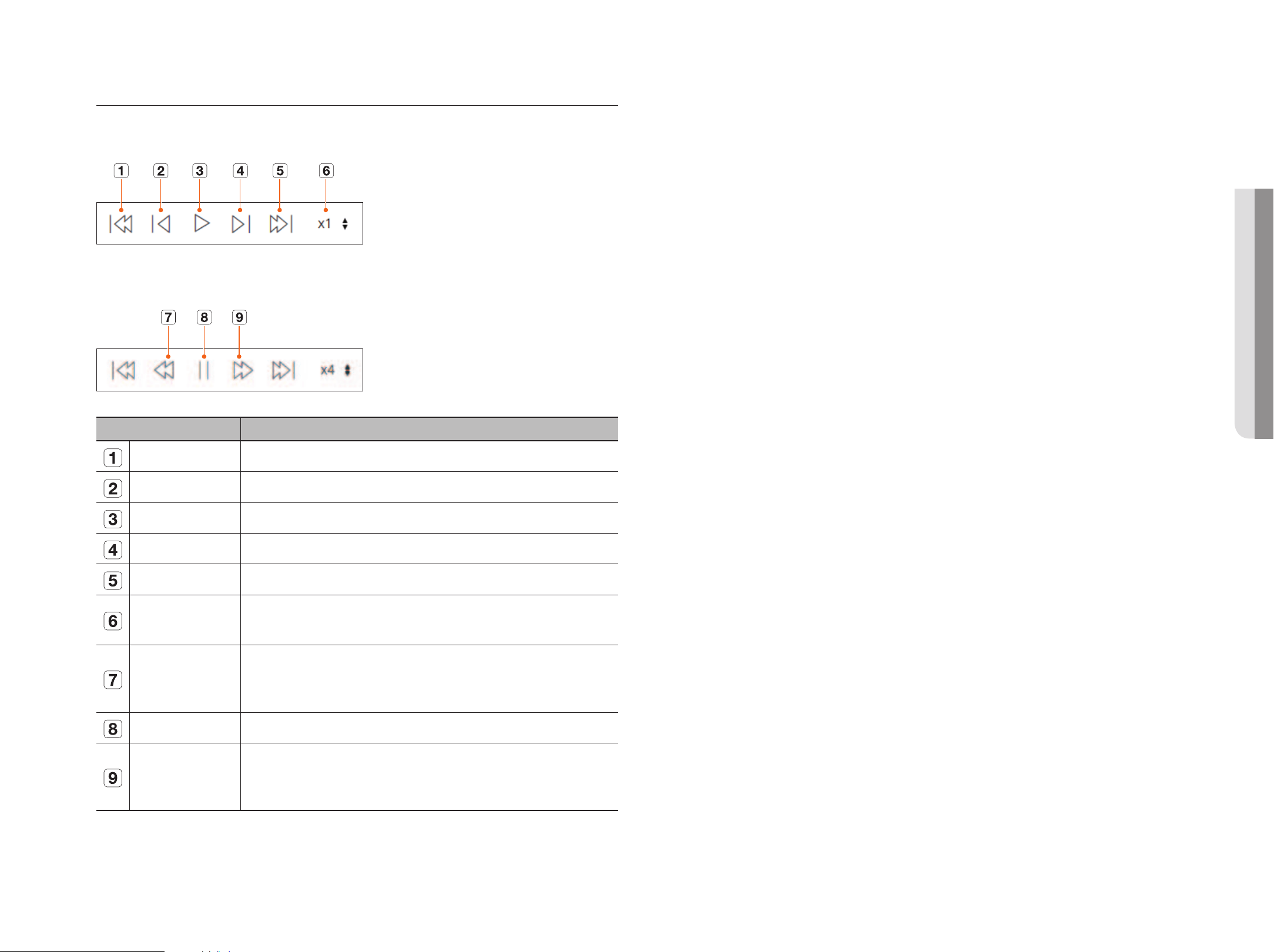
English _105
Play button name and Function
Paused state
Playback state
Name Description
Previous event Go to the previous event video.
Previous frame Moves backward to the key frame (I-frame).
Playback Play the video.
Next frame Moves forward one frame or more.
Next event Go to the next event video.
Speed
Select the video playback speed.
Speed : x1/8, x1/4, x1/2, x1, x2, x4, x8, x16, x32, x64, x128, x256
Fast backward
It is used for reverse playback.
Speed : -x1/8, -x1/4, -x1/2, -x1, -x2, -x4, -x8, -x16, -x32, -x64, -x128, -x256
■
Depending on the split screen, the maximum speed may be limited.
Pause Pause the video.
Fast forward
It is used for forward playback.
Speed : x1/8, x1/4, x1/2, x1, x2, x4, x8, x16, x32, x64, x128, x256
■
Depending on the split screen, the maximum speed may be limited.
• P Lay
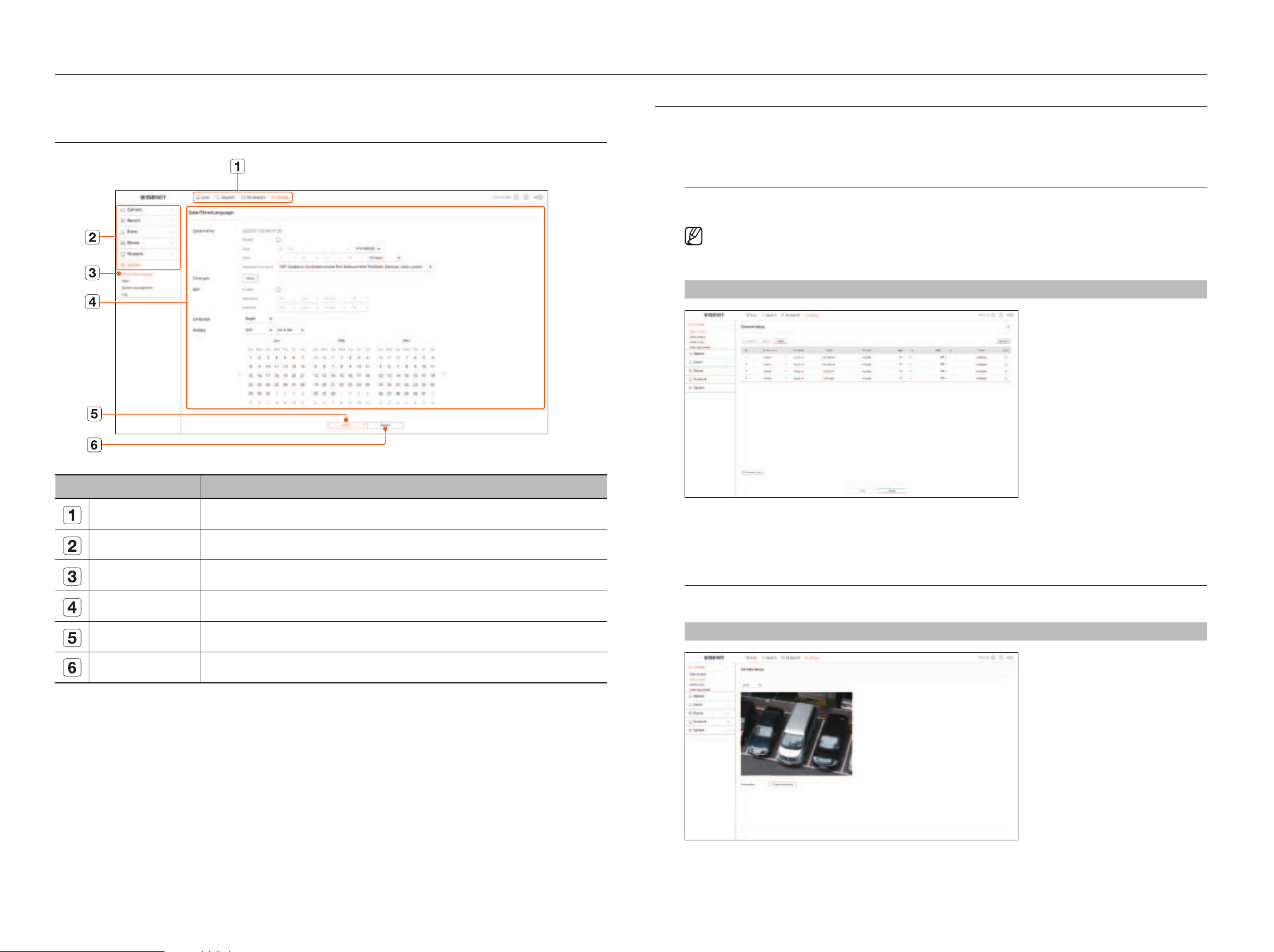
106_ setup viewer
You can configure the Recorder settings remotely on the network.
sCreen Layout oF the setuP VieWer
Name Description
Menu Click each menu to go to the menu screen.
Top menu list Configure the settings or select a parent item to change the existing settings.
Sub-menu list Among the sub-menus of selected parent menu, select a desired item to set.
Detailed Menu Click desired item's input field to change and enter a desired value.
Apply Apply the modified settings.
Revert Revert to the settings used before the change.
setting the CaMera
You can check a list of cameras that are connected to the Recorder and configure the necessary settings.
For details, refer to the "setup > setting the Camera" page in the Table of Contents.
Channel setup
You can register a network camera for each channel and make a connection between them.
■
When you register a camera for the first time in the "Setup > Camera > Channel setup" menu, the camera setup screen will be displayed.
For details, refer to the "Getting Started > Camera Setup" page of the table of contents.
setup > Camera > Channel setup
●
When you click the <upgrade> button, you can check the camera’s version, upgrade version, and status and
upgrade it.
Camera setup
You can change the video settings of network cameras registered for each channel by accessing the web viewer.
setup > Camera > Camera setup
setup viewer
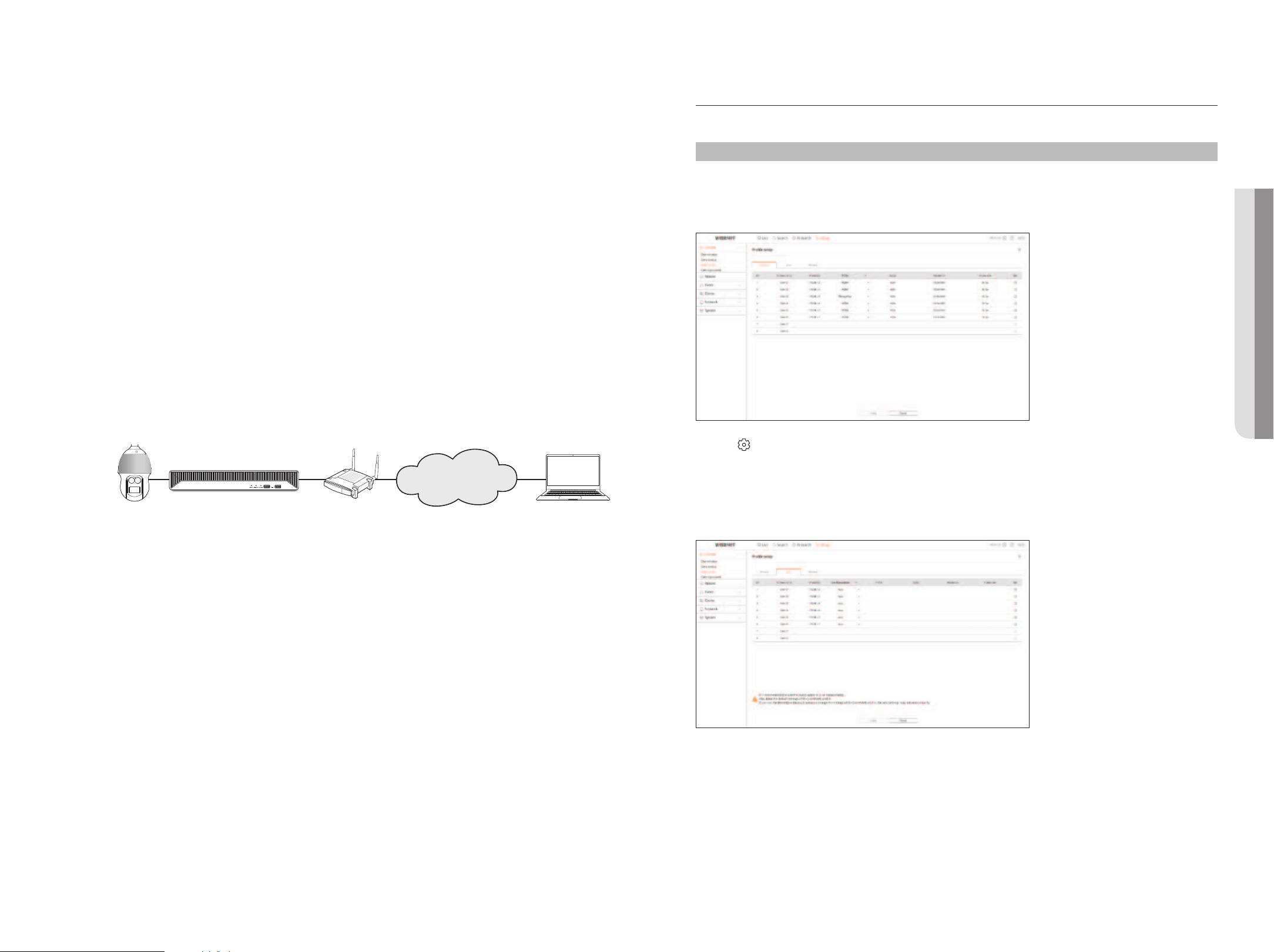
English _107
●
When you click the <Camera webviewer> button, a new camera web browser window is opened.
– This is not supported if the camera is connected to the RTSP protocol.
– This is not supported if the camera is connected to DDNS or a URL.
– It supports the version specified below or later for each Q/P/X series camera.
(QND-7010R series : 1.04, QND-7080R series : 1.02, QND-6010R series : 1.02,
QND-6070R series : 1.01, P series : 1.01)
– When you are connecting to the camera web page on a closed network, a camera that does not support the
universal web will not be able to output an image.
– The cam proxy port's default settings are automatically set in sequence as many as the number of channels
supported by Recorder. If you want to change the proxy port, then select the port setup menu.
– 4 channels (10001-10004), 8 channels (10001-10008), 16 channels (10001-10016),
32 channels (10001-10032), 64 channels (10001-10064)
example) defaults of cam proxy ports for each product
●
4-channel model : 10001-10004
●
8-channel model : 10001-10008
●
16-channel model : 10001-10016
●
32-channel model : 10001-10032
●
64-channel model : 10001-10064
– When connecting outside the closed network as shown in the figure, the port forwarding setting of the
camera proxy port is required for the router.
Recorder
Network Camera
IP router Remote PC
Internet
– If there are multiple Recorders within the closed network, each cam proxy port should be set using a
different port.
– If DDNS and Quick Connect are enabled, port forwarding will be automatically set.
– Chrome, Edge and Safari (Mac OS) browsers are supported.
Profile setup
You can set the profile for a network camera.
setup > Camera > Profile setup
record
You can set the recording profile for a network camera.
●
Click < > to change the profile settings. You can add or delete profiles, and change the settings by accessing
the camera's Web Viewer.
Live
You can change the live transfer settings of the network camera.
• setuP VieWer
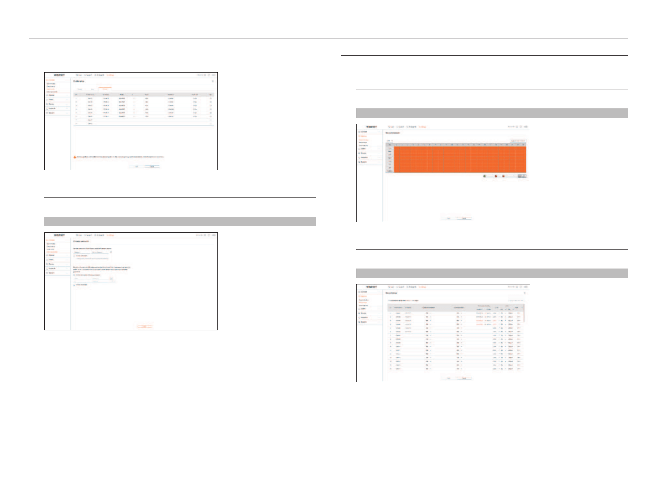
108_ setup viewer
setup viewer
remote
You can set the video profile transmitted to the network.
Camera Password
You can change the passwords of all registered cameras at once.
setup > Camera > Camera password
setting the reCording
For details, refer to the "setup > setting the recording" page in the Table of Contents.
record schedule
If you set a recording schedule for a specific date and time, the recording will start at that specific time.
setup > record > record schedule
record setup
Select a type of the normal/event recording frame rate for each channel.
setup > record > record setup
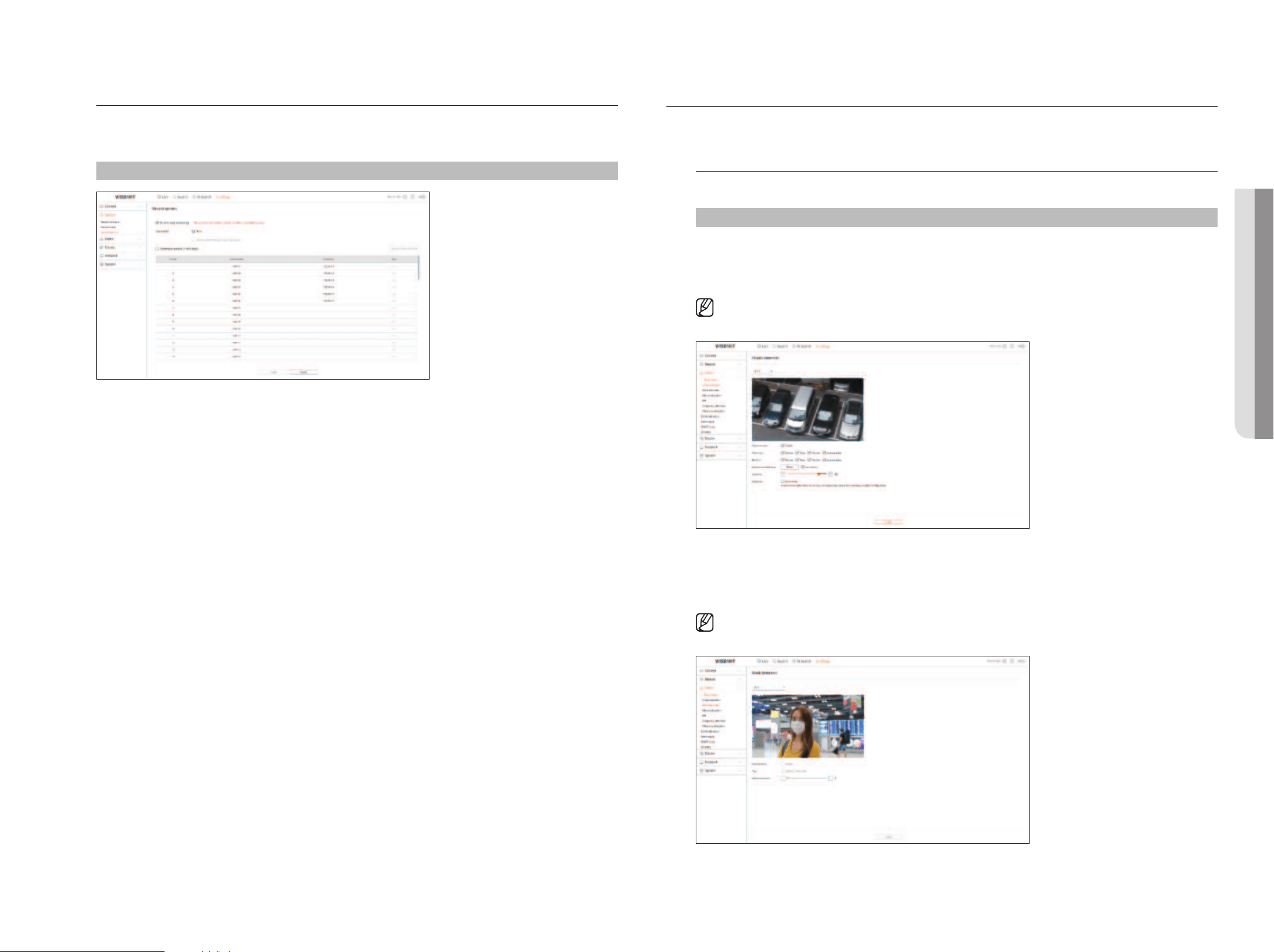
English _109
record options
You can set the hard disk recording option.
■
You can set the recording duration separately for each channel.
setup > record > record options
setting the eVent
For details, refer to the "setup > setting the event" page in the Table of Contents.
event setup
You can set detailed settings for each channel's event detection mode.
setup > event > event setup
object detection
You can change the AI object detection event setup.
■
The object detection function is displayed only when connected Wisenet AI camera.
Mask detection
You can change the mask detection event setup.
■
Settings and operating specifications may differ depending on the recorder model and camera.
• setuP VieWer
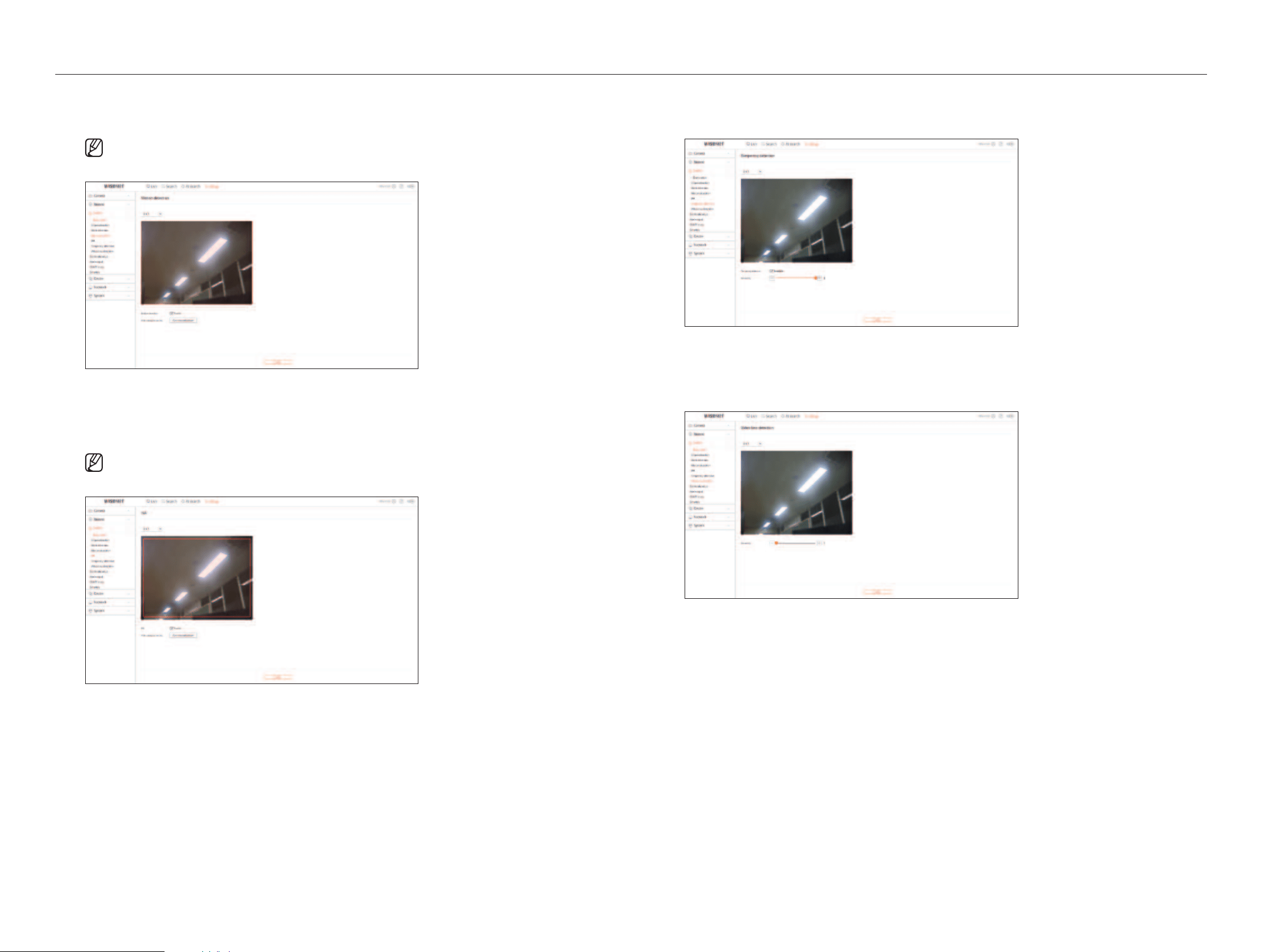
110_ setup viewer
setup viewer
Motion detection
You can change the settings for motion detection events.
■
Detailed video analysis can be set by accessing the Camera webviewer.
iVa
You can change the settings for Intelligent Video Analytics (IVA) events.
■
Detailed video analysis can be set by accessing the Camera webviewer.
tampering detection
You can change the tampering detection event setup.
Video loss detection
You can change the video loss detection event setup.
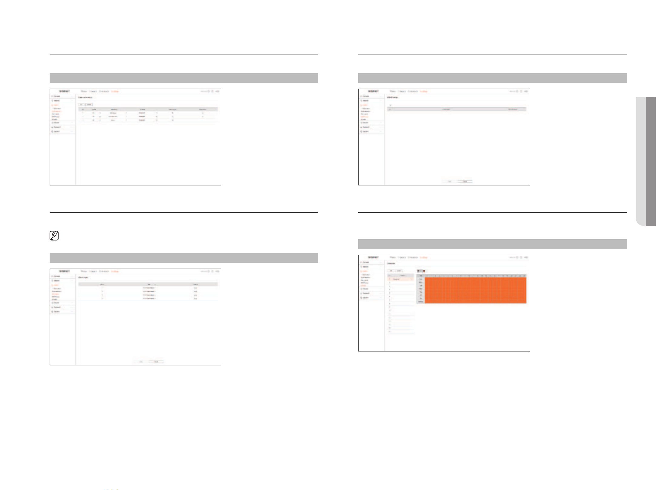
English _111
event rule setup
You can set the event trigger and action rule to output an alarm when an event occurs.
setup > event > event rule setup
alarm input
You can set the operation of the alarm sensor.
■
This function is not supported in some models.
setup > event > alarm input
onViF setup
You can set the camera registered with the Onvif protocol.
setup > event > onViF setup
schedule
Whether to output an alarm can be scheduled according to the day and time.
The initial setting will be an event sync, and an alarm will be sent only when an event occurs.
setup > event > schedule
• setuP VieWer
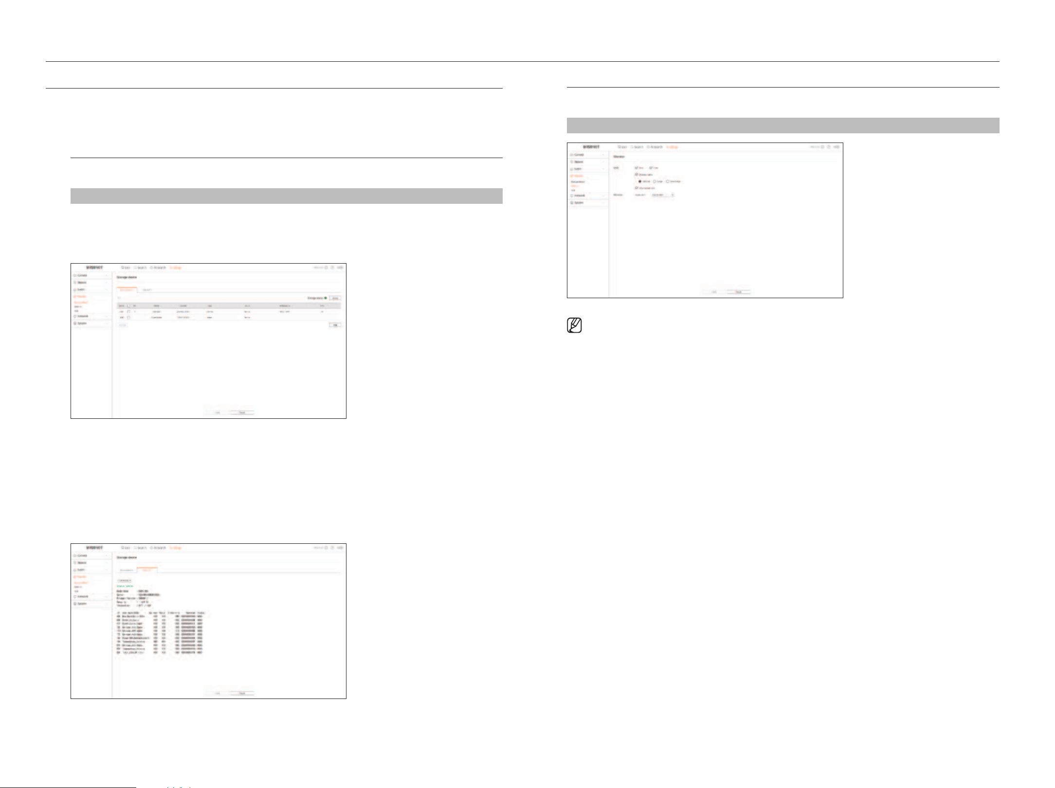
112_ setup viewer
setup viewer
setting the deViCe
You can check a list of devices that are connected to the Recorder and configure the necessary settings.
For details, refer to the "setup > setting the device" page in the Table of Contents.
storage device
You can check and change the settings related to the data storage device.
setup > device > storage device
Management
You can check a storage device, amount of use, type of use and status of storage device.
●
ARB : Video that was not recorded due to disconnection from the camera can be backed up after the
connection with the camera is re-established.
Press the button and an <auto recovery backup (arb)> window is opened.
For details, refer to the "setup > setting the device > storage device" page in the Table of Contents.
s.M.a.r.t
You can check the connection status and details of the hard disk mounted in the recorder.
Monitor
You can set the information displayed on the monitor as well as the output system.
setup > device > Monitor
■
If the screen does not work properly, see “Troubleshooting (FAQ)” in the Appendix.
■
The Monitor Setup settings control the monitor connected to the Recorder.
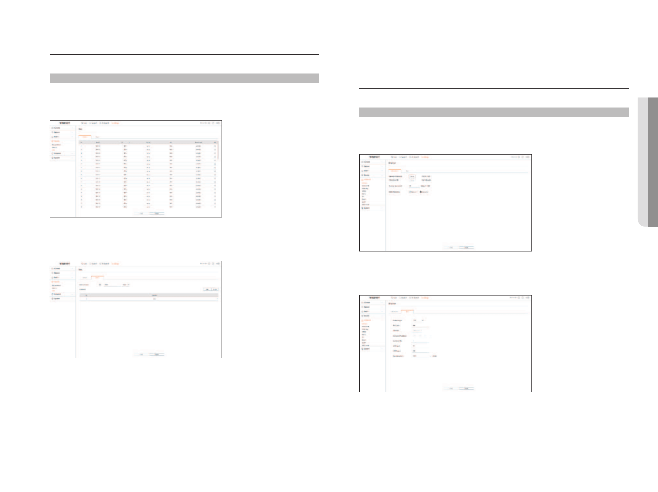
English _113
tex t
You can set the POS device text display and event text settings.
setup > device > text
device
Relevant values of a POS device connected to Recorder can be set.
event
It is possible to set total amount conditions and keywords to display events of a POS device.
setting the netWork
For details, refer to the "setup > setting the network" page in the Table of Contents.
iP & Port
A remote user can access the Recorder via the network to check the current mode and the IP address.
setup > network > iP & Port
iP address
Specify the network connection path.
Port
You can configure the protocol related settings.
• setuP VieWer
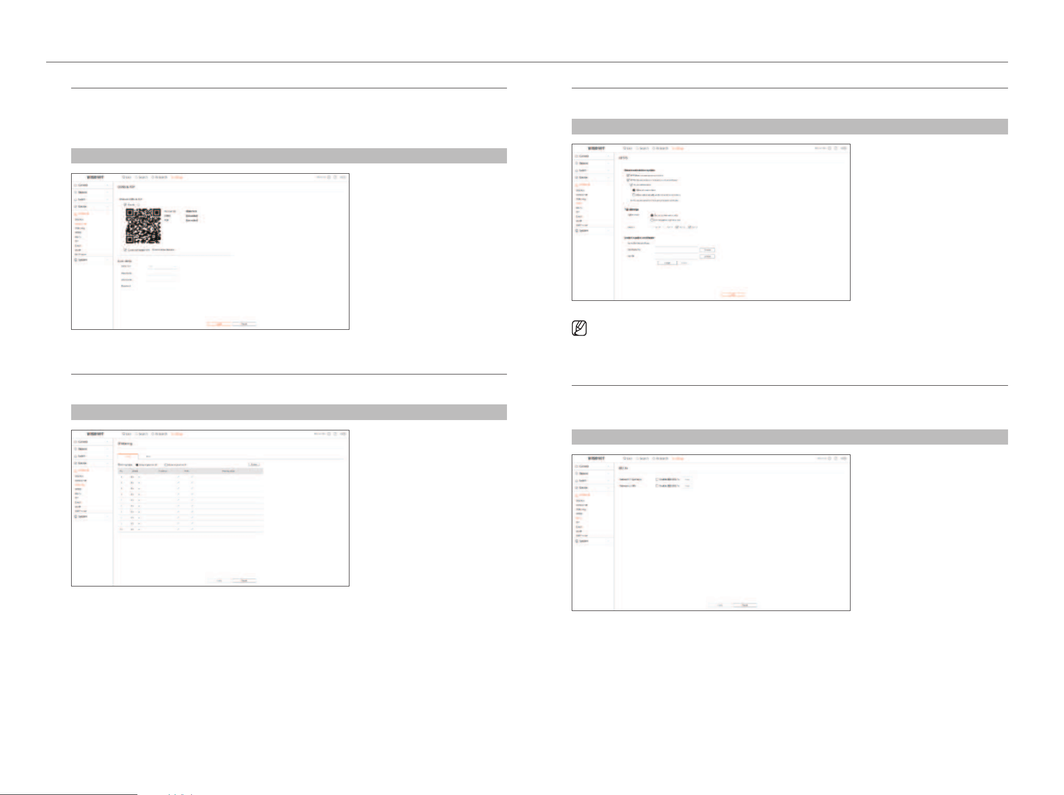
114_ setup viewer
setup viewer
ddns & P2P
A remote user can network a recorder using a DDNS address in a dynamic IP system. If you cannot connect with a
dynamic IP, you can easily access using a P2P service.
Before using Wisenet DDNS & P2P, please set up the network connection and DDNS first.
setup > network > ddns & P2P
iP Filtering
You can prepare the list of IP address to allow or block accesses to a specific IP address.
setup > network > iP filtering
httPs
You can select a security connection system or install public certificates.
setup > network > httPs
■
While using HTTPS, if you want to switch to HTTP, then abnormal operation can take place as the browser contains the setting values. You need
to change the URL to HTTP and reconnect or initialize the cookie setting of the browser.
802.1x
When connecting to a network, you can select whether to use the 802.1x protocol and install a corresponding
certificate.
setup > network > 802.1x
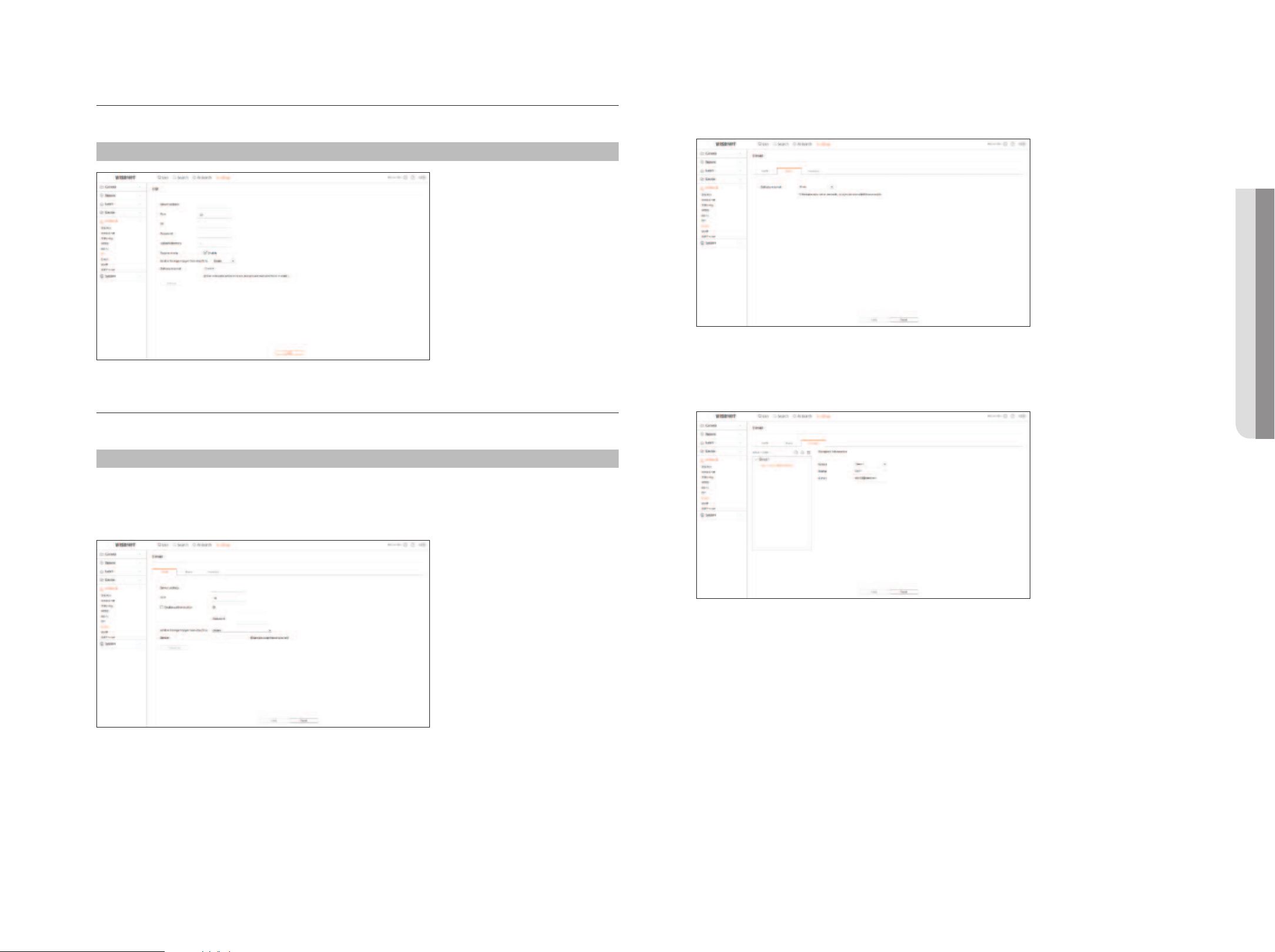
English _115
FtP
When an event occurs, you can create settings related to the FTP server to which images will be transferred.
setup > network > FtP
e-mail
You can specify the SMTP server that sends a mail if an event occurs and set the recipient group and users.
setup > network > e-mail
sMtP
You can set the server that sends mails and specify if you use the authentication process.
event
You can set the event interval and specify which events the server sends mails for.
recipient
You can set groups and recipients to receive emails.
• setuP VieWer
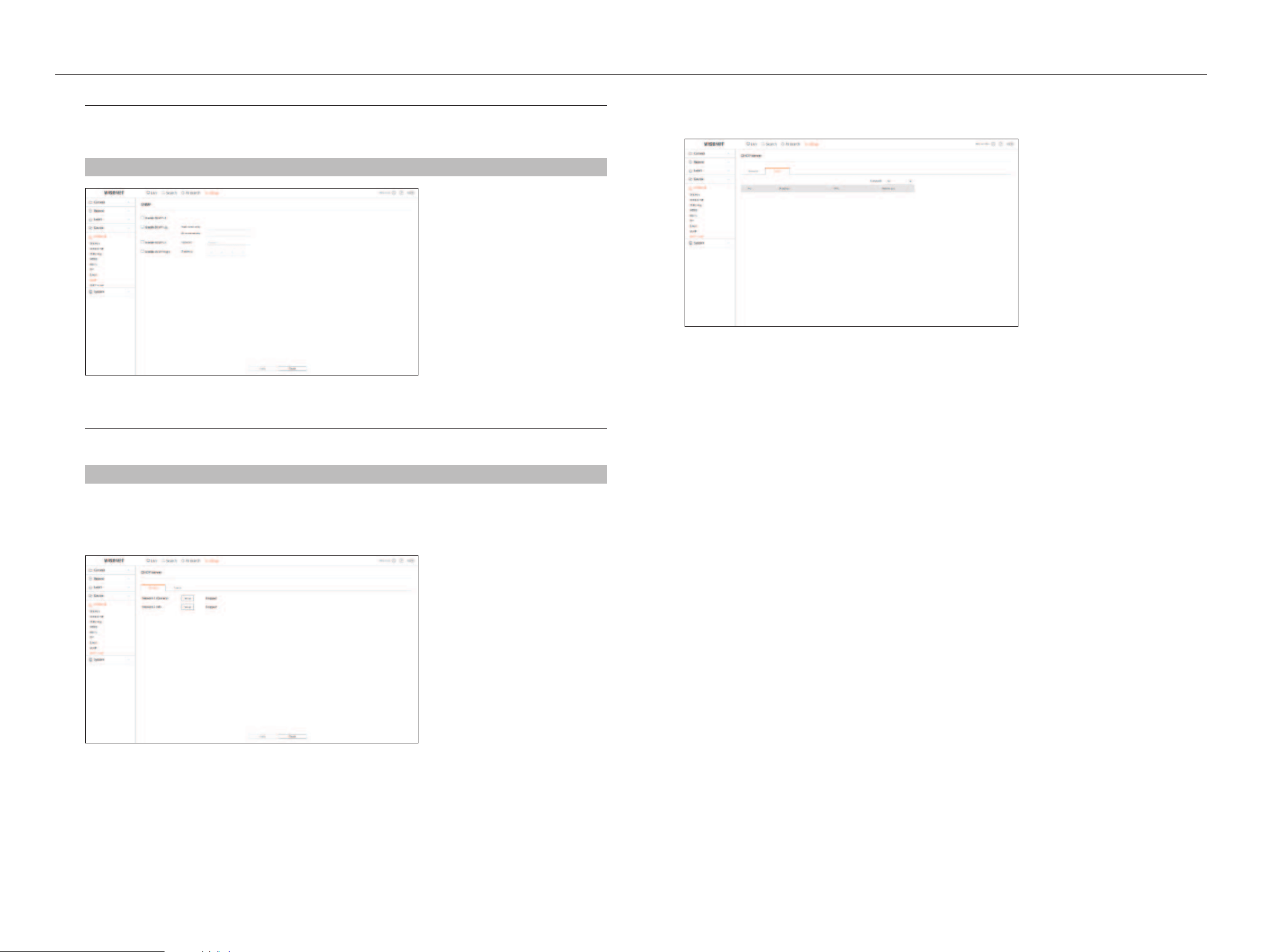
116_ setup viewer
setup viewer
snMP
Using the SNMP protocol, the system or network administrator can remotely monitoring the network devices and
sets the environment.
setup > network > snMP
dhCP server
You can set the network camera IP address and check the details by setting up a DHCP server.
setup > network > dhCP server
network
You can set the internal DHCP server and assign an IP address to the network camera.
status
You can check the IP and MAC currently used through the DHCP server, and the connected network port.
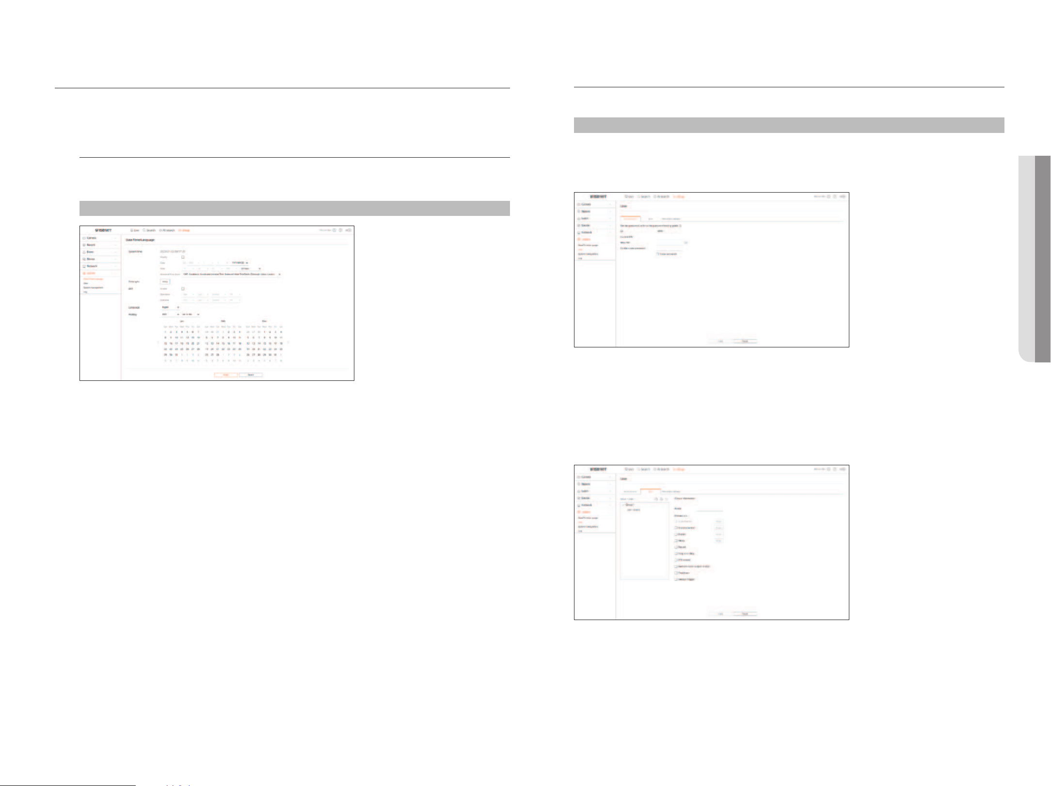
English _117
setting the systeM
You can configure the various settings of the Recorder system.
For details, refer to the "setup > setting the system" page in the Table of Contents.
date/time/Language
You can check and setup the current Date/Time and time related properties, as well as the language used for the
interface on the screen.
setup > system > date/time/Language
system time
Set the date and time.
time sync
Set the time synchronization.
dst
During the summer, Daylight Saving Time (DST) advances clocks one hour forwards from the standard local time
zone.
Language
Select a preferred language for the Recorder.
holiday
A user can select specific dates as holidays according to their own preferences.
user
You can manage users, such as adding or deleting users and granting different authorities for each user.
setup > system > user
administrator
You can change the admin ID or the password.
■
ID allows alphanumeric characters only.
■
If the admin ID is not used for access, you cannot change the ID.
■
If the ID being used is changed, you will be automatically logged out.
user
You can add, change or remove a user or users.
• setuP VieWer
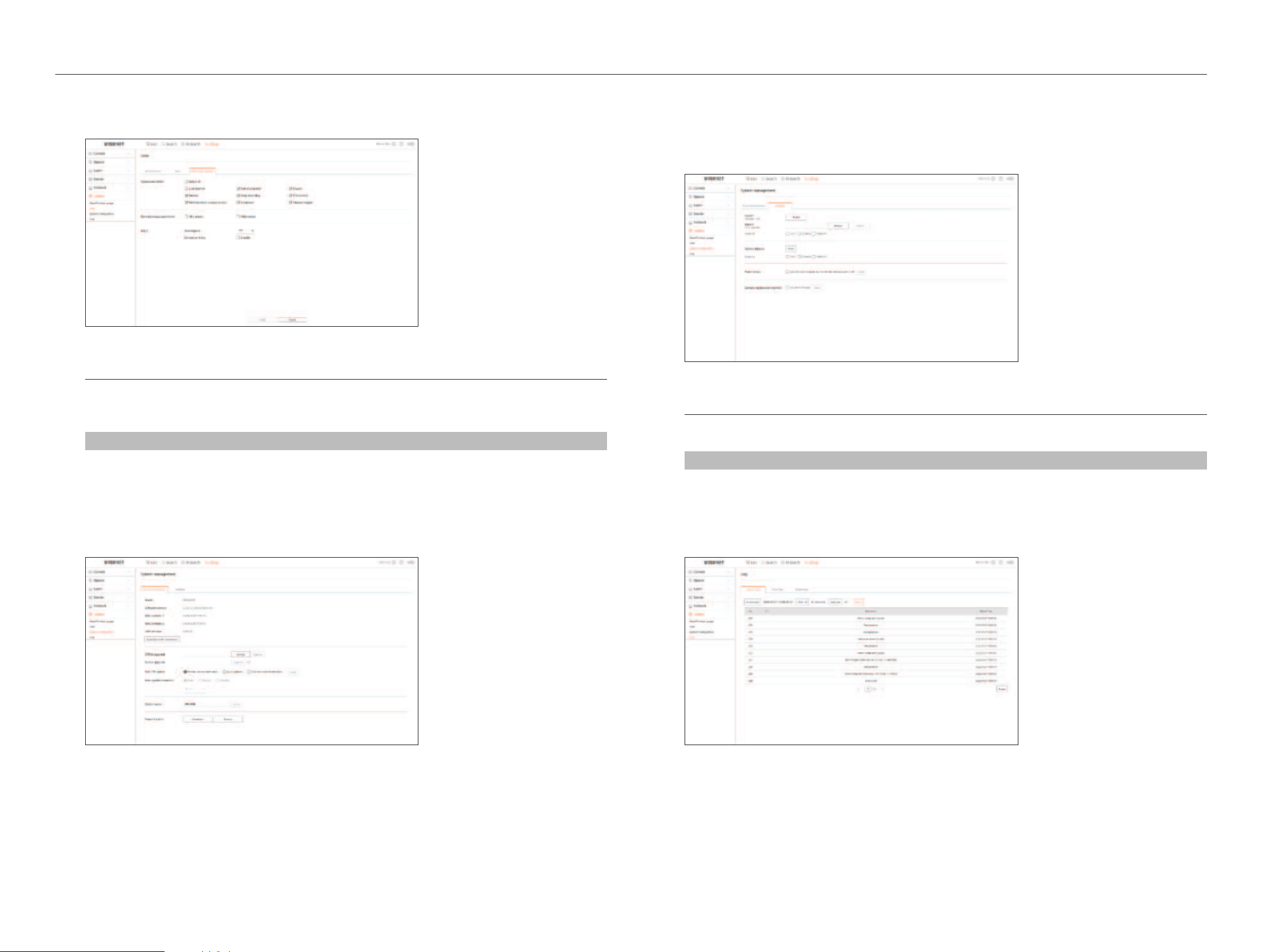
118_ setup viewer
setup viewer
restriction settings
You can set the user permission.
system Management
You can check the current system version and update to a new version, export data, setting initialization, and
more.
setup > system > system management
Product information
You can see information of the current system.
Check the model name, software version, and MAC address.
You can search for a file from the recorder connected to the PC to perform an upgrade.
settings
Using a storage device, you can apply the current configuration of Recorder to another Recorder.
Press the Initialization button to return the network settings to their factory default state. Items in the
<exception> category are excluded from the initialization.
Log
You can check the log information related to system, events, and export.
setup > system > Log
system log
System related log information such as system startup, system shutdown, and menu setting change can be
retrieved.
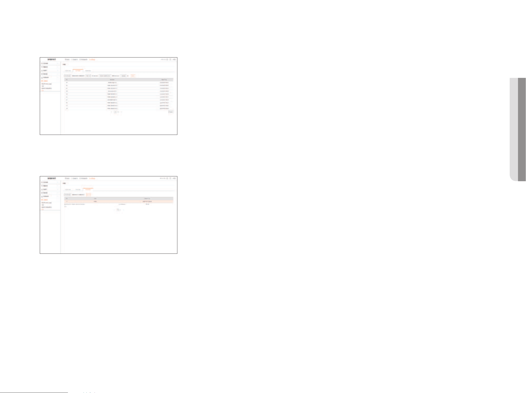
English _119
event log
The event log lists recorded events, such as sensor events, camera events, or image losses.
export log
You can search the user who performed the export and the execution time and details (time, channel, device, file
type).
• setuP VieWer
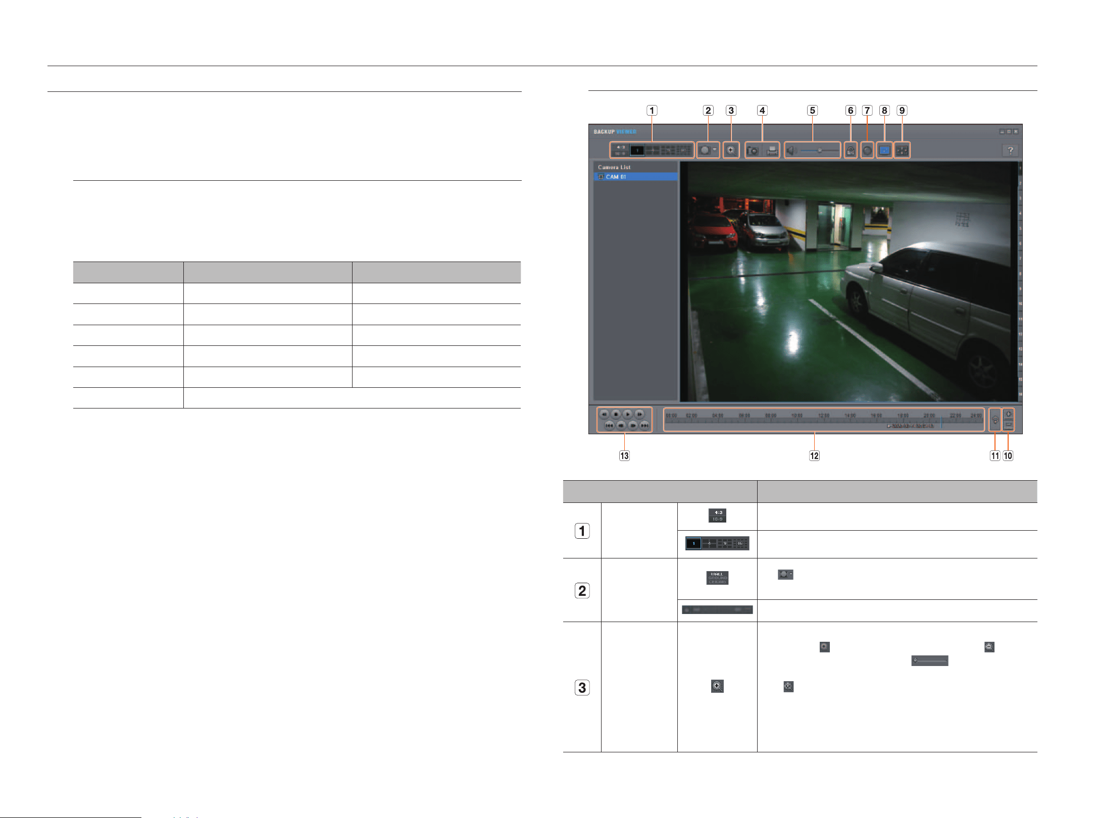
120_ export viewer
seC baCkuP VieWer
You can play a file that is backed up in the format of SEC.
Backup in SEC format produces backup data file, library file and self-executable viewer file.
If you run the backup file viewer, the backup data file will be played.
recommended system requirements
PCs with a lower specification than the recommended below may not fully support forward/backward and
highspeed playback.
PC specifications
Name Minimum requirements Recommended
CPU Intel Pentium 2.5GHz or more Intel i7(3.5GHz) or more
RAM 4GB or more 8GB or more
HDD 200GB or more 500GB or more
VGA memory 512MB or more 1GB or more
Display resolution 1280x1024 or higher 1920x1080 or higher
OS Windows 7, 8, 10
export viewer
screen Layout of the backup Viewer
XRN-1620B2_CAM 01
H264(1920x1080), NONE
2020-05-14 20 :54 :13
Name Description
Split screen
Selects screen ratio to display.
The screen is changed to a split screen.
Fisheye view mode
IIf < > is pushed, it is possible to change to a fisheye installation type. It is possible to
select wall/ground/ceiling mode according to the installation place.
The fisheye view mode on the current screen can be changed independently on each split.
Digital Zoom
Enlarge the image by up to 100 times as big as the current one.
Press the Zoom In ( ) button the enlarge the image; press the Zoom Out ( ) button
to shrink the image. You can also use the slide bar (
) in the pop-up window to
zoom in/out.
Press (
) on a size-changed video to restore the default zoom factor (100%). If you enlarge
the image by more than 200%, the enlarged area will be marked on the digital zooming
screen. Click on the marked area and move it to a desired position.
The digital zooming is applied to all backup viewer. When the digital zooming is canceled, the
video size will restore the default rate of 100%.
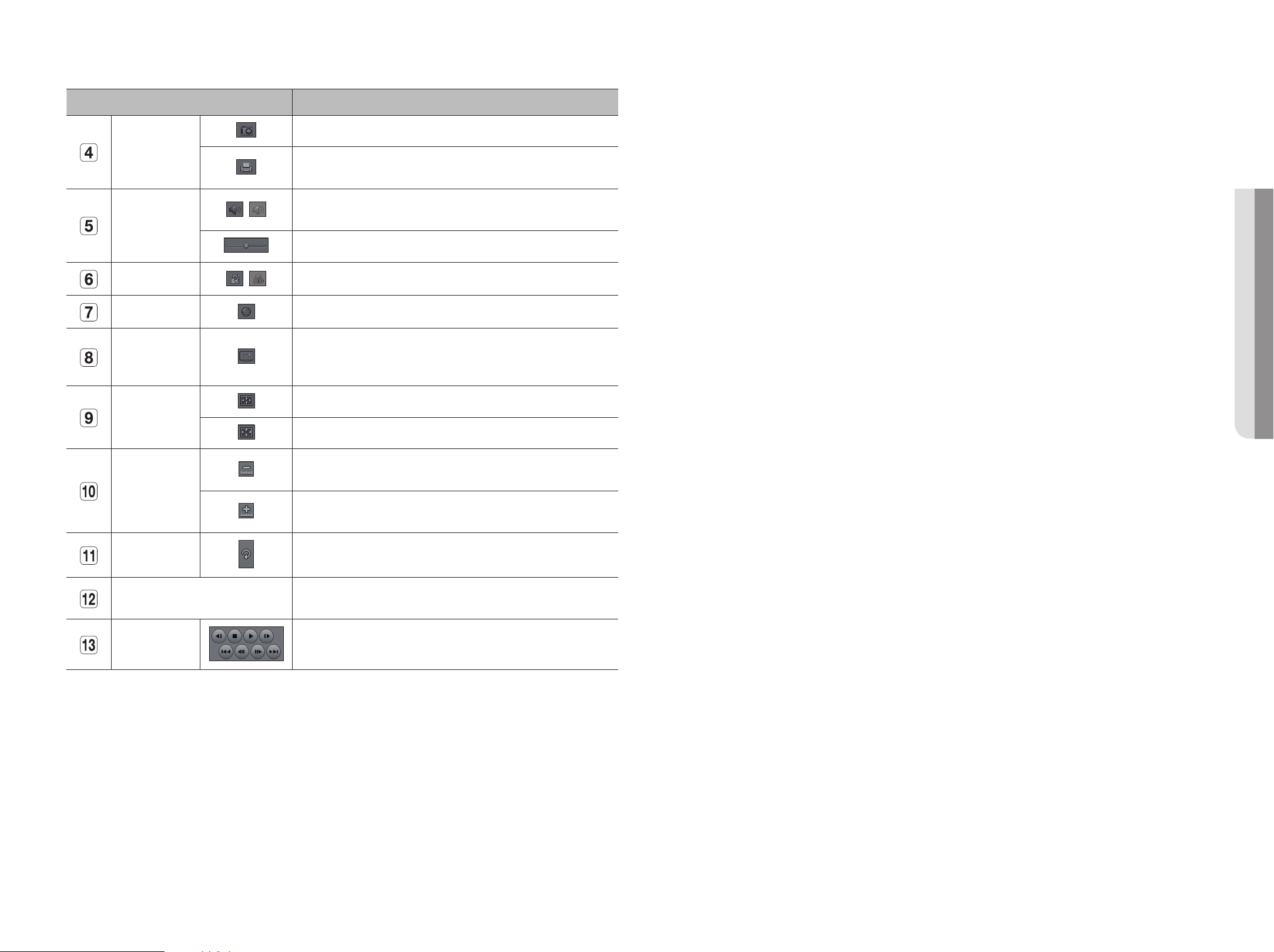
English _121
Name Description
Screen Printout
Saves the current video's image as in an image file. Supports
JPEG
file format.
Prints out the current screen. You should have installed the appropriate printer driver before
you can print out the screen.
Audio
/
A toggle button. Each time you press this button, the audio output will toggle between
activated and deactivated.
You can adjust the volume level from 0 to 100.
Watermark
/
Press the button to enable file tampering detection, to detect data file forging.
Deinterlace You can enable the De-interlace function.
Show OSD
Check the
OSD
checkbox to display the
OSD
information on the backup playback screen.
Information such as backup date, day of the week, time, model name, and channel number
will be displayed on the screen.
Maintain aspect
ratio/Full screen
Maintains the aspect ratio of the playback screen.
Plays the video on a full screen.
Enlarge/Reduce
Timeline
Collapses the time range that is displayed on the range bar of the storage time.
You can collapse the range bar until the overall range is shortened to 24 hours.
Enlarges the time range that is displayed on the range bar of the storage time. You can
enlarge the range bar until the overall range is extended to 1 minute.
Restore Timeline Restores the timeline to the default.
Display of storage time range
Displays the time range of a stored video file.
You can move the gridline of the range bar to select a time point to play.
Playback Control You can adjust the video playback of the timeline.
• exPort VieWer
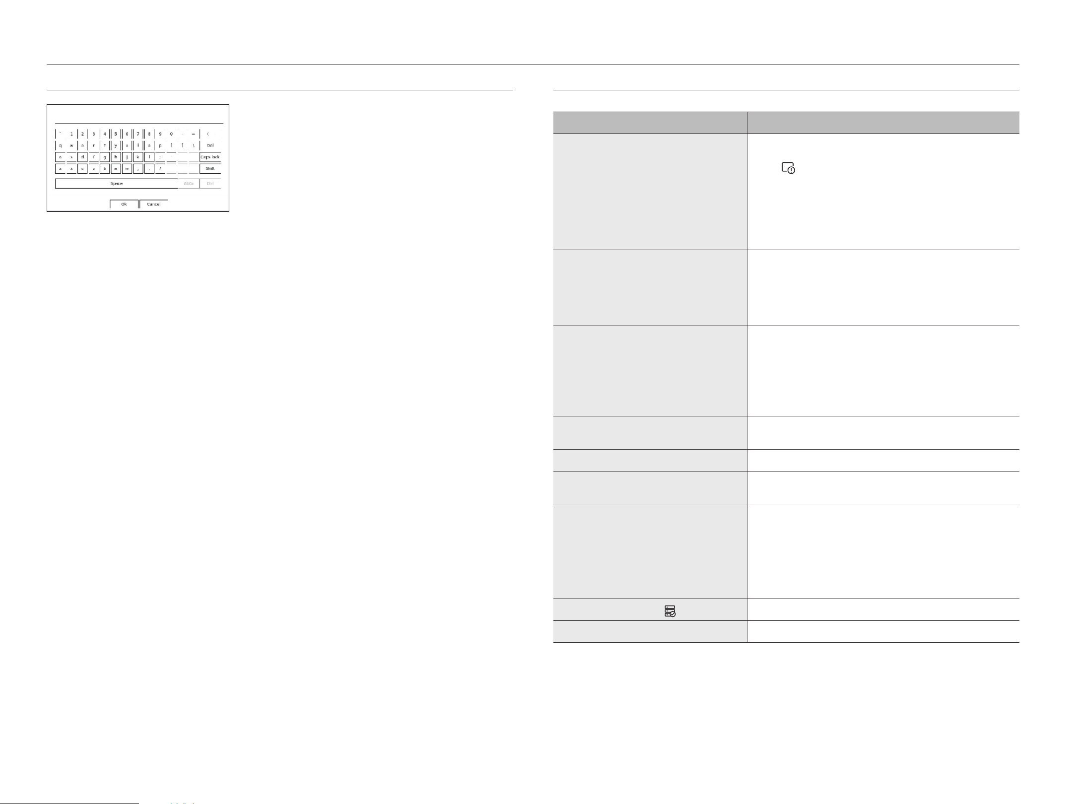
122_ appendix
using VirtuaL keyboard
1. For alphanumeric inputs, the virtual keyboard window appears.
2. Using a mouse, click on the desired character tab.
3. Select
<
ok
>
.
Entered word is applied.
■
If you want to enter a special character or uppercase letters, select <Caps lock> or <Shift>.
■
Using the virtual keyboard is the same to a normal keyboard use in your region.
■
Your ID can contain any combination of upper/lowercase alphabet letters and numbers.
■
If the password length is 8 to 9 digits, you can combine at least three different types of the following characters : upper/lowercase alphabets, numbers, and
special characters.
■
If the password length is 10 digits or more, you can combine at least two different types of the following characters : upper/lowercase alphabets, numbers,
and special characters.
troubLeshooting
Problem Action
Live video will be slow or cut off.
●
The frame number set for multiple data transmission set in camera or network environment
could differ from the actual rate of transmission.
Click <
> at the bottom of the screen to check the number of incoming frames per
channel and the actual number of frames played.
When you register a camera, the Live4NVR profile will be created by default.
If necessary, go to “Setup > Camera > Profile setup > Edit” and change the number of
frames.
●
If you keep seeing video slow down or cut off, then check the network environment or camera
condition.
The system does not turn on and the indicator on the front
panel does not work at all.
●
Check if the power supply system is properly connected.
●
Check the system for the input voltage from the power source.
●
If the problem persists even after you have taken the above actions, check the power supplier
and replace it with a new one if necessary.
●
Check inside if the cables are properly connected. (SMPS, FRONT)
The video input is okay, but the videos of some channels are
not properly displayed or are abnormally displayed (e.g. black
screen, B/W screen).
●
Check if the camera is properly supplied with power.
●
Check the state of the cable connected to the camera and reconnect it after replacing or
disconnecting it.
●
Check the video output connecting the camera's Web Viewer.
●
Check if the network port is properly connected and the network setting is set correctly.
●
Change the hub supporting Gigabit, it may solves.
The screen displays the logo image repeatedly.
●
This may occur from a problem with the main board, or the related software is corrupt.
Contact the nearest service center for more information.
The Channel button does not work on the Live screen.
●
The Channel button does not work if the current screen is in the event monitoring mode.
The cursor will not move to the Start button when I start the
calendar search.
●
Check if the channel and the date that you want to play are marked with the V symbol.
Both channel and date should be checked before you can start playing with the Start button.
The screen of the connected monitor is displayed abnormally or
not displayed at all.
●
Check if the necessary cables are connected to the monitor properly.
●
Some monitors do not support the Recorder output (HDMI1 or HDMI2/VGA). Check the
monitor resolution.
– HDMI1 : 3840x2160(30 Hz), 1080P, 720P, 1280x1024
– HDMI2/VGA : 1920x1080, 1280x720, 1280x1024, 1024x768
●
Disconnect the monitor cable from the recorder, and connect again.
Logo screen on bootup stalls in the < > state.
●
The HDD may have problems. Visit your nearest customer service center to check the HDD.
No response controlling PTZ in the live viewer.
●
Check the registered Camera if it support PTZ function.
appendix
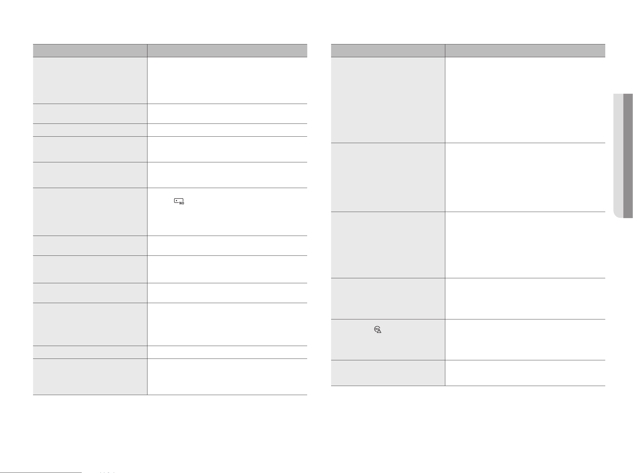
English _123
Problem Action
The camera is not connected or the PC fails to connect to the
product.
●
Check if the network cable is connected properly.
●
Ensure that you have set Network - Connection Mode.
●
Check the IP setting of the PC or camera.
●
Try the Ping Test.
●
Check if there is a different device near the product uses the same IP.
I registered a camera, but the web viewer does not show live
video.
●
After registering a camera, a user need to edit/save the desired layout, before the screen split
mode and live screen fit for the setting appears.
The input camera image is too bright or too dark.
●
Check the registered camera settings in “Setup > Camera > Camera setup”.
The time setup window will pop up.
●
This message is displayed if there occurs a problem with the time setting of the internal clock
or an error in the clock itself.
Contact the retailer or the service center for more information.
The time bar is not displayed in Search mode.
●
The timeline can switch between normal and extension mode.
In extension mode, the time bar may not be displayed in the current timeline. Switch to
normal mode or use the left or right button to navigate through the time bar.
The "NO HDD" icon and an error message are displayed.
●
If you do not format your purchased HDD at all or in a format supported by Recorder, a “NO
HDD” icon (
) will be displayed at the top left. When the “NO HDD” icon is displayed, go
to “Setup > Device > Storage device” and check the HDD connection status and format the
HDD.
●
If the problem persists in a normal condition, contact the nearest service center to have the
HDD checked by the service personnel.
I have installed an additional HDD on the Recorder but it does
not recognize the HDD.
●
See the compatibility list to check if the additional HDD is supported by the Recorder. For the
compatibility list, contact the retailer where you purchased the Recorder.
I have connected an external storage device (USB Memory, USB
HDD) to the Recorder but the Recorder seems not to recognize
it.
●
See the compatibility list of external storage devices to check if the connected device is
supported by the Recorder. For the compatibility list, contact the retailer where you purchased
the Recorder.
If I press the ESC key in full screen mode of the Web Viewer, the
system does not switch to a normal split mode.
●
Press the ALT +TAB keys to select 'ACTIVE MOVIE' and press the ESC key again. The system will
switch to a normal split mode.
It is difficult to configure the network for default search, export,
and router use.
●
For more information, refer to the user manual.
●
If you want to check the basics of the product for a quick start, refer to the Quick Guide
(export, search).
●
If you use the router for network connection, refer to the “Connecting and Setting the
Network” of the Quick Guide.
I forgot the password.
●
Contact the Recorder administrator for help.
Exported data cannot be played on a PC or recorder.
●
When setting the file format for exporting, first decide whether the device to be played is a PC
or a recorder before setting.
●
When playing on a PC, the export file format must be SEC.
●
When playing on a recorder, the export file format must be recorder.
Problem Action
Recording does not work.
●
If your player does not display a Live image at all, that indicates recording does not work so
first check if you see an image on the screen.
●
Recording does not work if the recording settings are not properly configured.
Scheduled Record : Specify a desired time in "Setup > Record > Record schedule".
Recording will start at the specified time.
– Continuous : Recording will proceed in any conditions at the specified time.
– Event : When an event occurs, recording will perform only if the event is of alarm,
motion detection and video loss. If there is no event found, recording will not perform.
– Continuous/Event : If there is no event found, continuous recording will perform.
Whereas, if an event occurs, event recording will perform.
The image quality of the recording data is not good.
●
Increase the resolution and quality level in "Setup > Camera > Profile setup > Record".
– Resolution : Select a bigger size when specifying the recording size.
The recording image in the CIF format shows a deteriorated quality as it is enlarged
from a small-sized image.
– Frame rate : Set the level of frame rate high.
●
If you increase the resolution and the recording quality, the data size increases accordingly.
So the HDD will be filled faster. Overwriting will overwrite the existing data so recording will
proceed at a shorter interval.
Frame rate of the actual recording does not match that of
configured to the camera.
●
If multiple profiles were applied to one camera for video transmission, the actual video stream
can be serviced by the camera at a lower frame rate than specified.
Configure your camera to use one profile for data streaming as possible.
For example, if you set the same profile for recording and network profiles, the actual
recording is made at the specified frame rate.
Still, live video display using split screen mode may apply yet another profile to camera in
accordance with the used screen mode.
Note that allowed limit bitrate for recording / recording settings should be set to be bigger
values than that of camera's feed.
In the recording setting screen, the permitted level for a specific
channel is displayed in orange.
●
If the input data is greater than the permitted level for each channel, it is displayed in orange.
Set the permitted data limit to higher than the amount of input data.
●
If the sum of input data for each channel exceeds the limit, the alarm icon will be displayed. In
this case, the channel exceeding the input limit does not record the entire frame, but it records
the main frame only (one or two per sec).
In the live screen, the < > icon is displayed and the
message window saying “Record data size exceeded limitation.
Only key frames are recorded. Please check the record settings.”
pops up.
●
If the sum of input data for each channel exceeds the limit, the alarm icon and the pop up
window will be displayed. In this case, the channel exceeding the input limit does not record
the entire frame, but it records the main frame only (one or two per sec).
●
Set the permitted data limit to higher than the amount of input data entered in the "Setup >
Record > Record setup" menu.
Recording is not performed in accordance with the settings.
●
If the recording status displays 'Exceeds the maximum hard disc performance', set the
recording size according to the recording performance specifications for each HDD condition.
For details, refer to the "Setup > Setting the Recording” page in the Table of Contents.
• aPPendix
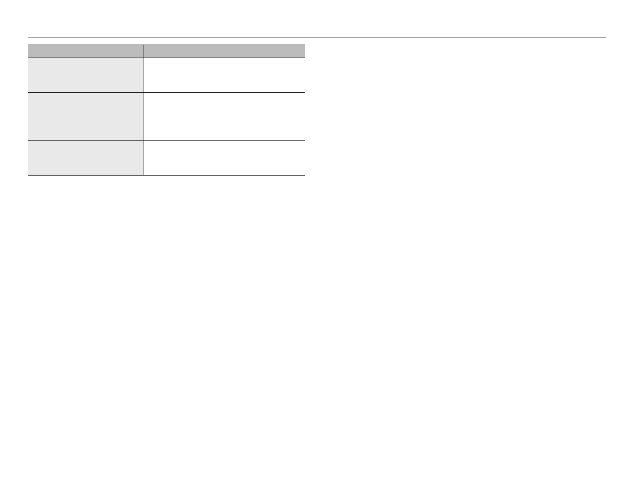
124_ appendix
appendix
Problem Action
The recording screen will slow down.
●
Check whether the recording performance specifications for each HDD condition match the
actual recording settings.
For details, refer to the "Setup > Setting the Recording” page in the Table of Contents.
●
If the data volume of a video exceeds the playing performance, only the main frame is played.
If recording loss persists continuously
●
Reset the camera recording profile to let the entire recording bps size fit the recording
performance for each HDD condition.
For details, refer to the "Setup > Setting the Recording” page in the Table of Contents.
●
Check the HDD status and determine whether inspection or replacement is necessary.
For details, refer to the "Setup > Setting the Device > Storage device" page in the Table
of Contents.
When registering your camera in PnP mode, if the camera
doesn't get registered but the logo keeps loading attempting
access.
●
If your camera is using a manual IP, the IP bandwidth might not match with the Network 1 IP
bandwidth of the recorder. Please set it to the identical IP bandwidth.
●
If your camera is in DHCP mode, see if the Network 1 port is functioning in the DHCP server of
the recorder.