Thank you for purchasing a Sealey product. Manufactured to a high standard, this product will, if used according to these instructions,
and properly maintained, give you years of trouble free performance.
IMPORTANT: PLEASE READ THESE INSTRUCTIONS CAREFULLY. NOTE THE SAFE OPERATIONAL REQUIREMENTS, WARNINGS & CAUTIONS. USE
THE PRODUCT CORRECTLY AND WITH CARE FOR THE PURPOSE FOR WHICH IT IS INTENDED. FAILURE TO DO SO MAY CAUSE DAMAGE AND/OR
PERSONAL INJURY AND WILL INVALIDATE THE WARRANTY. KEEP THESE INSTRUCTIONS SAFE FOR FUTURE USE.
CT995.V4 Issue: 1 22/10/18
Original Language Version
© Jack Sealey Limited
Refer to instruction
manual
Wear eye
protection
PETROL ENGINE COMPRESSION
TEST KIT 8PC
MODEL NO: CT955.V4
1.
SAFETY
WARNING! Ensure all Health & Safety, local authority and general workshop practice regulations are strictly adhered to when using
tools.
DO NOT
use equipment if damaged.
Maintain the
equipment in good and clean condition for best and safest performance.
If required, ensure vehicle to be worked on is adequ
ately supported with axle stands, ramps and chocks.
Wear approved eye protection. A full range of personal safety equipment is available from your Sealey stockist.
Wear suitable clothing to avoid snagging.
DO NOT
wear jewellery and tie back long hair.
Account for all tools and equipment being used and
DO NOT
leave them in, on or near engine.
When not in use, place in protective case and store in a safe, dry, childproof area.
IMPORTANT:
Always refer to the vehicle manufacturer’s service instructions, or a proprietary manual, to establish the current procedure
and data. These instructions are provided as a guide only.
WARNING!
The warnings, cautions and instructions referred to in this manual cannot cover all possible conditions and situations that
may occur. It must be understood that common sense and caution are factors which cannot be built into this product, but must be
applied by the operator.
2.
INTRODUCTION
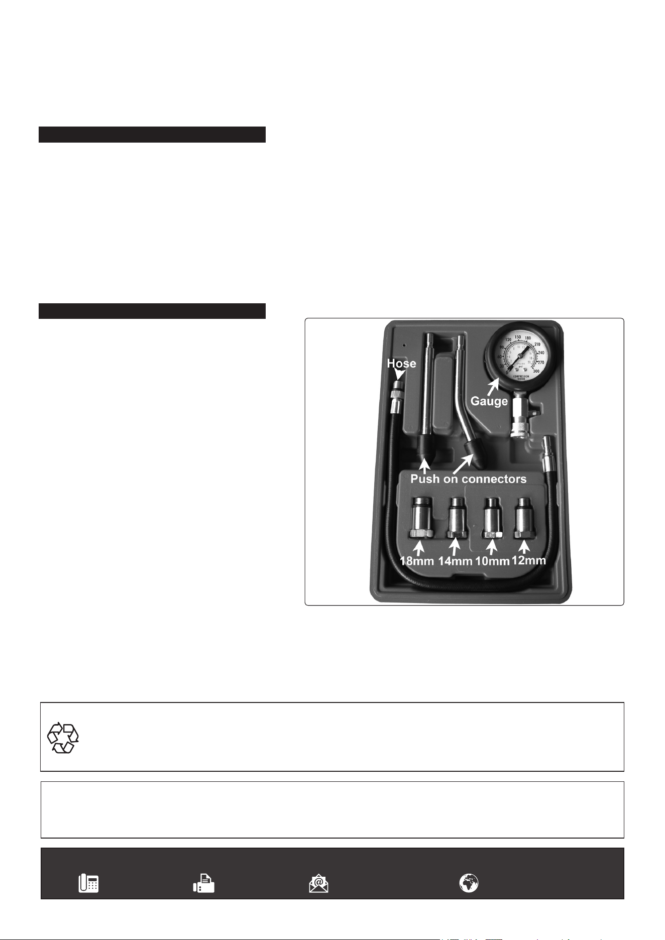
C
ompression tester tted with Ø63mm gauge reading up to 300psi (20kg/cm²). Kit includes 130mm straight and angled push-on connectors,
300mm exible extension with 10, 12, 14 and 18mm adaptors. Supplied in storage case.
3.
OPERATION
3.1.
TEST PROCEDURE
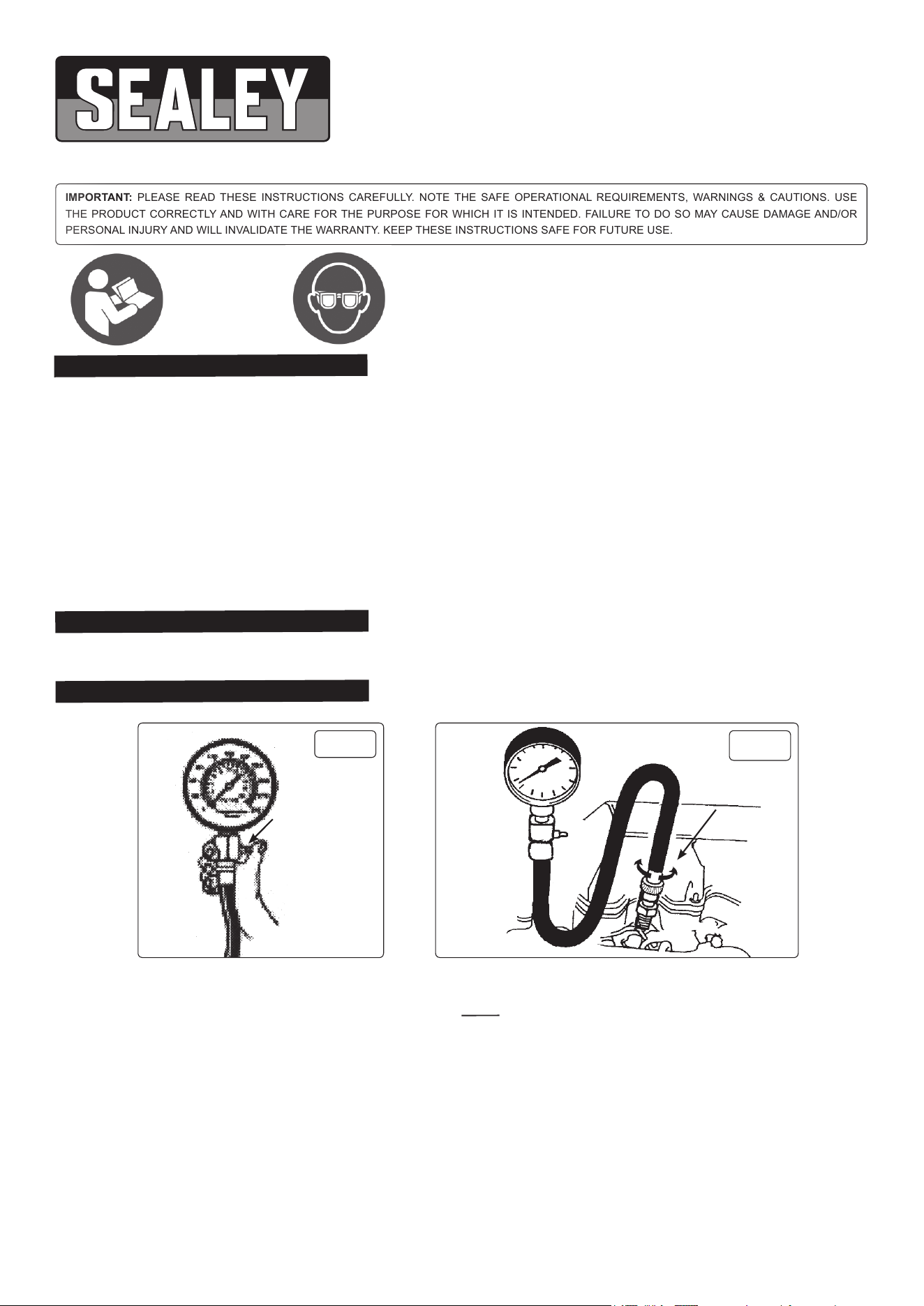
WARNING: Always release the pressure via the Release Valve
before
disconnecting the tester.
Press the release valve slowly to release the pressure gradually. Refer to Fig.1.
NOTE:
A variation in compression readings between cylinders is often a better indication of engine problems than the absolute values
of compression.
3.2.
Run the engine until it reaches the normal operating temperature.
3.3.
Stop the engine and disconnect all spark plug leads, numbering them according to the cylinder to which they were connected.
3.4.
Loosen all spark plugs by about half a turn, but
DO NOT
remove them.
3.5.
Using an air hose or wire brush, remove all the dirt and debris from the spark plug wells.
3.6. Remove the spark plugs and place them on a clean, flat surface in the cylinder order in which they were removed.
3.7. Remove the air filter and set the throttle plates to the wide open position, taking care not to damage the linkage or throttle components.
IMPORTANT: After test, failure to return the throttle plates to the closed position before starting the engine can cause serious
damage to the engine.
3.8.
Disconnect the ignition system, following the manufacturer’s recommendations in the vehicle servicing manual.
3.9.
Select the spark plug adaptor required for the vehicle. Screw the adaptor to the hose. Screw the spark plug adaptor and hose assembly
into a spark plug well. Hand tighten only.
DO NOT
use a wrench. Refer to Fig.2.
RELEASE
VALVE
Fig.1
HAND
TIGHTEN
Fig.2
3.10. Connect the coupling on the gauge to the hose. Ensure the coupling is fully engaged.
3.11. Crank the engine for at least five compression strokes, or until the pressure reading on the gauge stops rising.
3.12. Record the compression reading, then push the side release valve to relieve the pressure.
3.13. Repeat the test and record the reading. Relieve the pressure and remove the hose and adaptor from the spark plug well.
3.14. Repeat for the remainder of the cylinders.
3.15. You may also connect one of the Push On Connectors straight to the gauge coupling to aid quick installation. Select either the straight
or angled stem for easiest access.
4. TEST RESULTS
4.1. GAUGE READINGS
4.2. On a normal cylinder, the gauge needle should travel up the scale on each compression stroke until it reaches peak value. All cylinders
should indicate a pressure that is within the vehicle manufacturer’s specifications; the reading should not vary by more than 10%
from cylinder to cylinder.
4.3. If the gauge needle does not travel up the scale or if it remains at the same value for several strokes and then starts to climb, the
problem could be a valve sticking.
4.4. If the compression reading is considerably higher than the vehicle manufacturer’s specification, the problem may be carbon build-up in
the cylinder. It may also indicate that either the piston, or the cylinder head, has been modified.
4.5. If a reading on two adjacent cylinders is 20psi (or more) lower than the other cylinders, the problem may be a cracked cylinder head or
defective main gasket. Under these conditions, both coolant and oil may be found in both cylinders.
4.6. If the readings are low, or vary widely between cylinders, pour 5ml of SAE 30 oil into each cylinder and retest them. If the
readings increase considerably, the problem may be poorly seated, or worn, piston rings. If the readings remain about the
same, the
valves and/or associated components may be the problem. A burnt or damaged piston may also cause the same results.
5. COMPLETION OF TESTS
c
5.1. Clean, re-gap and reinstall the spark plugs in
the same order in which they were removed, or
install new spark plugs.
5.2. Reconnect each spark plug lead to the plug it was
connected to prior to removal.
5.3. Return the throttle plates to the closed position.
IMPORTANT: After test, failure to return the
throttle plates to the closed position before
starting the engine can cause serious damage to
the engine.
5.4. Reconnect the ignition system wiring disconnected in
paragraph 3.8.
Sealey Group, Kempson Way, Suffolk Business Park, Bury St Edmunds, Suffolk. IP32 7AR
01284 757500 01284 703534 sales@sealey.co.uk www.sealey.co.uk
Note: It is our policy to continually improve products and as such we reserve the right to alter data, specifications and component parts without prior
notice.
Important: No Liability is accepted for incorrect use of this product.
Warranty: Guarantee is 12 months from purchase date, proof of which is required for any claim.
ENVIRONMENT PROTECTION
Recycle unwanted materials instead of disposing of them as waste. All tools, accessories and packaging should be sorted, taken to
a recycling centre and disposed of in a manner which is compatible with the environment. When the product becomes completely
unserviceable and requires disposal, drain any fluids (if applicable) into approved containers and dispose of the product and fluids
according to local regulations.
CT995.V4 Issue: 1 22/10/18
Original Language Version
© Jack Sealey Limited