Loading ...
Loading ...
Loading ...
06
Trouble Code And Troubleshooting
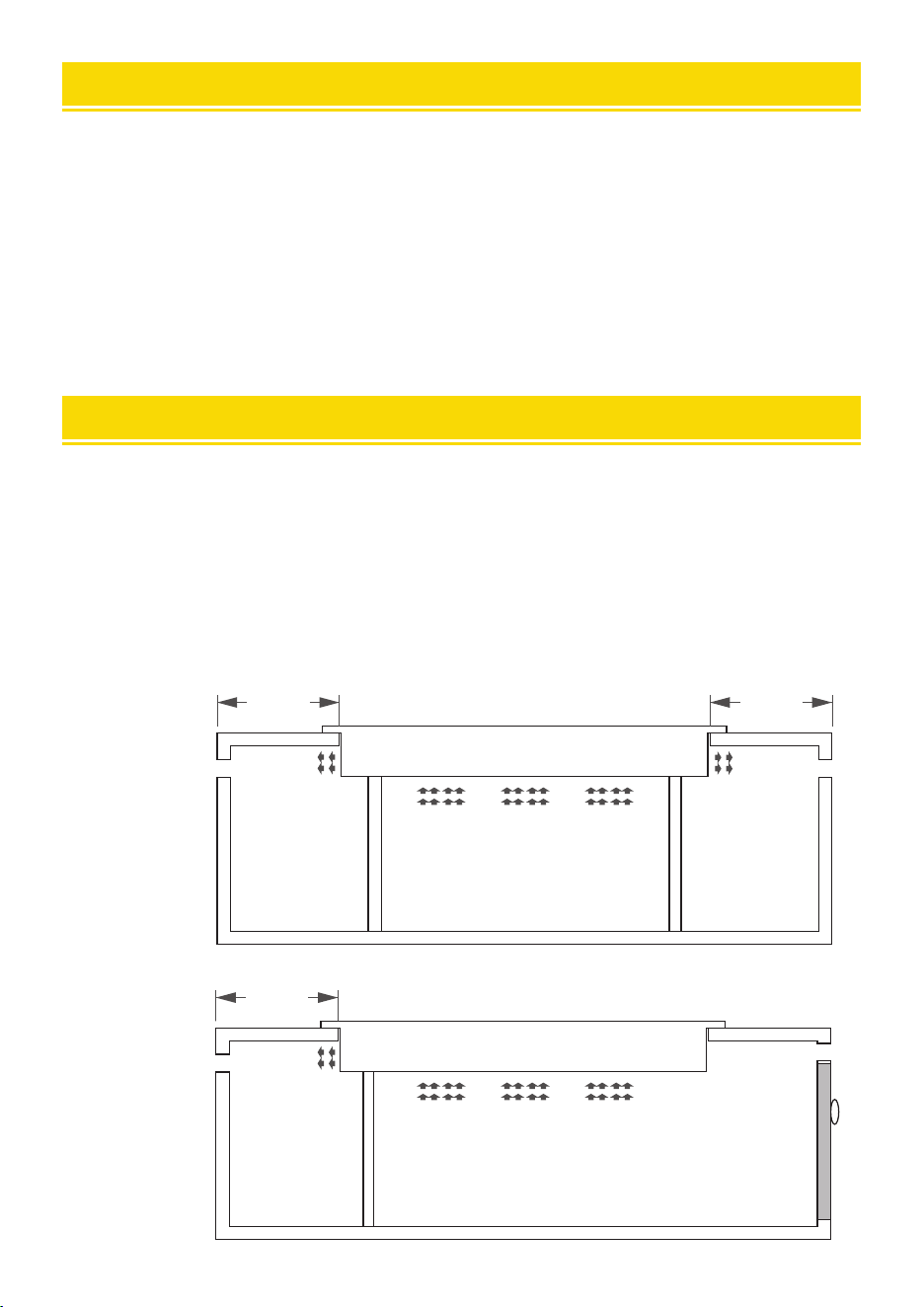
Heat Dissipation Structure Installation Drawing
When the machine is embedded, to ensure the normal use of the machine and better heat
dissipation.
Requirements:
1. 30-50mm heat dissipation should be left on the left and right sides and behind.
2. The counter interior should be as large as possible to ensure that enough cold air is sucked into the
machine.
3. Inlet air (cold air) must be separated from outlet air (hot air) space.
4. The air inlet and outlet space of the counter leave air roar.
Front view
Induction cooker
The cold air
Counter space
Heat ow Heat ow
Exhaust roar Exhaust roar
left
30.00mm
right
30.00mm
Side view
Induction cooker
The cold air
Counter space
Heat ow
Exhaust roar
after
30.00mm
Air inlet
Cupboard door
E0------- no pot
E1------- The voltage is lower than 90.
E2------- Excessive voltage (voltage higher than 270)
E3------- Furnace suace oveemperature or sensor damage sho circuit
E4------- Furnace suace sensor open
E5-------IGBT oveemperature or fan damage does not work
E6------- The IGBT sensor is open
E8------- The control board is connected to the main power supply board
Voltage adaptation range: 90--270 VOLTS
Loading ...
Loading ...
Loading ...