Thermal & Optical Bi-spectrum PTZ
Network Camera
User Manual

Legal Information
©2023 Hangzhou Microimage Software Co., Ltd. All rights reserved.
About this Manual
The Manual includes instructions for using and managing the Product. Pictures, charts,
images and all other information hereinafter are for description and explanation only. The
information contained in the Manual is subject to change, without notice, due to rmware
updates or other reasons. Please nd the latest version of this Manual at the HIKMICRO
website (
http://www.hikmicrotech.com
).
Please use this Manual with the guidance and assistance of professionals trained in
supporting the Product.
Trademarks
and other HIKMICRO's trademarks and logos are the properties
of HIKMICRO in various jurisdictions.
Other trademarks and logos mentioned are the properties of their respective owners.
Disclaimer
TO THE MAXIMUM EXTENT PERMITTED BY APPLICABLE LAW, THIS MANUAL AND THE
PRODUCT DESCRIBED, WITH ITS HARDWARE, SOFTWARE AND FIRMWARE, ARE
PROVIDED "AS IS" AND "WITH ALL FAULTS AND ERRORS". HIKMICRO MAKES NO
WARRANTIES, EXPRESS OR IMPLIED, INCLUDING WITHOUT LIMITATION,
MERCHANTABILITY, SATISFACTORY QUALITY, OR FITNESS FOR A PARTICULAR PURPOSE.
THE USE OF THE PRODUCT BY YOU IS AT YOUR OWN RISK. IN NO EVENT WILL HIKMICRO
BE LIABLE TO YOU FOR ANY SPECIAL, CONSEQUENTIAL, INCIDENTAL, OR INDIRECT
DAMAGES, INCLUDING, AMONG OTHERS, DAMAGES FOR LOSS OF BUSINESS PROFITS,
BUSINESS INTERRUPTION, OR LOSS OF DATA, CORRUPTION OF SYSTEMS, OR LOSS OF
DOCUMENTATION, WHETHER BASED ON BREACH OF CONTRACT, TORT (INCLUDING
NEGLIGENCE), PRODUCT LIABILITY, OR OTHERWISE, IN CONNECTION WITH THE USE OF
THE PRODUCT, EVEN IF HIKMICRO HAS BEEN ADVISED OF THE POSSIBILITY OF SUCH
DAMAGES OR LOSS.
YOU ACKNOWLEDGE THAT THE NATURE OF THE INTERNET PROVIDES FOR INHERENT
SECURITY RISKS, AND HIKMICRO SHALL NOT TAKE ANY RESPONSIBILITIES FOR
ABNORMAL OPERATION, PRIVACY LEAKAGE OR OTHER DAMAGES RESULTING FROM
CYBER-ATTACK, HACKER ATTACK, VIRUS INFECTION, OR OTHER INTERNET SECURITY
RISKS; HOWEVER, HIKMICRO WILL PROVIDE TIMELY TECHNICAL SUPPORT IF REQUIRED.
YOU AGREE TO USE THIS PRODUCT IN COMPLIANCE WITH ALL APPLICABLE LAWS, AND
YOU ARE SOLELY RESPONSIBLE FOR ENSURING THAT YOUR USE CONFORMS TO THE
APPLICABLE LAW. ESPECIALLY, YOU ARE RESPONSIBLE, FOR USING THIS PRODUCT IN A
MANNER THAT DOES NOT INFRINGE ON THE RIGHTS OF THIRD PARTIES, INCLUDING
Thermal & Optical Bi-spectrum PTZ Network Camera User Manual
i

WITHOUT LIMITATION, RIGHTS OF PUBLICITY, INTELLECTUAL PROPERTY RIGHTS, OR
DATA PROTECTION AND OTHER PRIVACY RIGHTS. YOU SHALL NOT USE THIS PRODUCT
FOR ANY PROHIBITED END-USES, INCLUDING THE DEVELOPMENT OR PRODUCTION OF
WEAPONS OF MASS DESTRUCTION, THE DEVELOPMENT OR PRODUCTION OF CHEMICAL
OR BIOLOGICAL WEAPONS, ANY ACTIVITIES IN THE CONTEXT RELATED TO ANY
NUCLEAR EXPLOSIVE OR UNSAFE NUCLEAR FUEL-CYCLE, OR IN SUPPORT OF HUMAN
RIGHTS ABUSES.
IN THE EVENT OF ANY CONFLICTS BETWEEN THIS MANUAL AND THE APPLICABLE LAW,
THE LATTER PREVAILS.
Thermal & Optical Bi-spectrum PTZ Network Camera User Manual
ii

Symbol Conventions
The symbols that may be found in this document are dened as follows.
Symbol Description
Danger
Indicates a hazardous situation which, if not avoided, will or
could result in death or serious injury.
Caution
Indicates a potentially hazardous situation which, if not avoided,
could result in equipment damage, data loss, performance
degradation, or unexpected results.
Note
Provides additional information to emphasize or supplement
important points of the main text.
Thermal & Optical Bi-spectrum PTZ Network Camera User Manual
iii

Safety Instruction
These instructions are intended to ensure that user can use the product correctly to avoid
danger or property loss.
Laws and Regulations
●
In the use of the product, you must be in strict compliance with the electrical safety
regulations of the nation and region.
Transportation
●
Keep the device in original or similar packaging while transporting it.
●
Keep all wrappers after unpacking them for future use. In case of any failure occurred,
you need to return the device to the factory with the original wrapper. Transportation
without the original wrapper may result in damage on the device and the company shall
not take any responsibilities.
●
DO NOT drop the product or subject it to physical shock. Keep the device away from
magnetic interference.
Power Supply
●
Check the input voltage before powering on the device to avoid damage.
●
CAUTION: If the fuse of the device can be replaced, replace it only with the same model
to reduce the risk of re or electric shock.
●
If a fuse is connected to the neutral wire and a double pole/neutral fusing occurs, parts
of the device that remain energized might represent a hazard during servicing after
operation of the fuse.
●
If the device uses a 3-prong power supply plug, it must be connected to an earthed
mains socket-outlet properly.
●
Do not touch the bare components (such as the metal contacts of the inlets) and wait
for at least 5 minutes, since electricity may still exist after the device is powered off.
●
For the permanently connected device without a disconnect equipment, a readily
accessible disconnect equipment shall be incorporated into the electrical installation of
the connected building.
●
For the permanently connected device without an overcurrent protection equipment, an
overcurrent protection equipment shall be incorporated into the electrical installation of
the connected building. The specications of the overcurrent protection equipment shall
not exceed that of the building.
●
For the permanently connected device without an all-pole mains switch, an all-pole
mains switch shall be incorporated into the electrical installation of the connected
building.
●
If the device is powered by terminals connected to the power cord, ensure correct
voltage and wiring of the terminals for connection to mains supply.
Thermal & Optical Bi-spectrum PTZ Network Camera User Manual
iv

●
Please purchase the charger by yourself. Input voltage should meet the Limited Power
Source (24 VDC, or 24 VAC) according to the IEC62368 standard. Please refer to
technical specications for detailed information.
●
Make sure the plug is properly connected to the power socket.
●
The socket-outlet shall be installed near the equipment and shall be easily accessible.
●
DO NOT connect multiple devices to one power adapter, to avoid over-heating or re
hazards caused by overload.
●
DO NOT touch the bare metal contacts of the inlets after the circuit breaker is turned off.
Electricity still exists.
●
+ identies the positive terminal(s) of equipment which is used with, or generates direct
current. - identies the negative terminal(s) of equipment which is used with, or
generates direct current.
Battery
●
Risk of explosion if the battery is replaced by an incorrect type. Dispose of used
batteries according to the instructions.
●
The built-in battery cannot be dismantled. Please contact the manufacture for repair if
necessary.
●
For long-term storage of the battery, make sure it is fully charged every half year to
ensure the battery quality. Otherwise, damage may occur.
●
This equipment is not suitable for use in locations where children are likely to be
present.
●
Improper replacement of the battery with an incorrect type may defeat a safeguard (for
example, in the case of some lithium battery types).
●
DO NOT dispose of the battery into re or a hot oven, or mechanically crush or cut the
battery, which may result in an explosion.
●
DO NOT leave the battery in an extremely high temperature surrounding environment,
which may result in an explosion or the leakage of ammable liquid or gas.
●
DO NOT subject the battery to extremely low air pressure, which may result in an
explosion or the leakage of ammable liquid or gas.
Installation
●
This device is suitable for use above 2 m only.
●
Install the device according to the instructions in Quick Start Guide. To prevent injury,
this device must be securely attached to the installation surface in accordance with the
installation instructions.
●
Never place the device in an unstable location. The device may fall, causing serious
personal injury or death.
●
The additional force shall be equal to three times the weight of the device but not less
than 50 N. The device and its associated mounting means shall remain secure during
the installation. After the installation, the device, including any associated mounting
plate, shall not be damaged.
Thermal & Optical Bi-spectrum PTZ Network Camera User Manual
v

●
Never place the equipment in an unstable location. The equipment may fall, causing
serious personal injury or death.
●
This equipment is for use only with corresponding brackets. Use with other (carts,
stands, or carriers) may result in instability causing injury.
●
The interface varies with the models. Please refer to the product datasheet for details.
●
If the device needs to be wired by yourself, select the corresponding wire to supply
power according to the electric parameters labeled on the device. Strip off wire with a
standard wire stripper at corresponding position. To avoid serious consequences, the
length of stripped wire shall be appropriate, and conductors shall not be exposed.
●
Make sure that the power has been disconnected before you wire, install, or disassemble
the device.
System Security
●
You acknowledge that the nature of Internet provides for inherent security risks, and our
company shall not take any responsibilities for abnormal operation, privacy leakage or
other damages resulting from cyber attack, hacker attack, however, our company will
provide timely technical support if required.
●
Please enforce the protection for the personal information and the data security as the
device may be confronted with the network security problems when it is connected to
the Internet. Please contact us when the device might exist network security risks.
●
Please understand that you have the responsibility to congure all the passwords and
other security settings about the device, and keep your user name and password.
Maintenance
●
If the product does not work properly, please contact your dealer or the nearest service
center. We shall not assume any responsibility for problems caused by unauthorized
repair or maintenance.
●
A few device components (e.g., electrolytic capacitor) require regular replacement. The
average lifespan varies, so periodic checking is recommended. Contact your dealer for
details.
●
Wipe the device gently with a clean cloth and a small quantity of ethanol, if necessary.
●
If the equipment is used in a manner not specied by the manufacturer, the protection
provided by the device may be impaired.
●
To reduce the risk of re, replace only with the same type and rating of fuse.
●
The serial port of the equipment is used for debugging only.
Using Environment
●
Make sure the running environment meets the requirement of the device. The operating
temperature shall be -40°C to 60°C (-40°F to 140°F), and the operating humidity shall be
95% or less, no condensing.
●
DO NOT expose the device to high electromagnetic radiation or dusty environments.
●
DO NOT aim the lens at the sun or any other bright light.
Thermal & Optical Bi-spectrum PTZ Network Camera User Manual
vi

●
The equipment shall not be exposed to dripping or splashing and that no objects lled
with liquids, such as vases, shall be placed on the equipment.
●
No naked ame sources, such as lighted candles, should be placed on the equipment.
●
For the device with ventilation openings, the ventilation openings should not be impeded
by covering the ventilation openings with items, such as newspapers, table-cloths, and
curtains. The openings shall never be blocked by placing the device on a bed, sofa, rug,
or other similar surface.
●
Keep a proper distance around the device for sufcient ventilation.
●
This device is suitable for mounting on concrete or other non-combustible surface only
to avoid re hazard.
●
This equipment is not suitable for use in locations where children are likely to be
present.
●
Provide a surge suppressor at the inlet opening of the equipment under special
conditions such as the mountain top, iron tower, and forest.
●
Burned ngers when handling the parts with symbol . Wait one-half hour after
switching off before handling the parts.
Emergency
●
If smoke, odor, or noise arises from the device, immediately turn off the power, unplug
the power cable, and contact the service center.
COMPLIANCE NOTICE: The thermal series products might be subject to export controls in
various countries or regions, including without limitation, the United States, European
Union, United Kingdom and/or other member countries of the Wassenaar Arrangement.
Please consult your professional legal or compliance expert or local government
authorities for any necessary export license requirements if you intend to transfer, export,
re-export the thermal series products between different countries.
Thermal & Optical Bi-spectrum PTZ Network Camera User Manual
vii

Contents
Chapter 1 Overview ................................................................................................................... 1
1.1 Brief Description ............................................................................................................ 1
1.2 Function .......................................................................................................................... 1
Chapter 2 Device Activation and Accessing ............................................................................ 2
2.1 Activate the Device via SADP ........................................................................................ 2
2.2 Activate the Device via Browser ................................................................................... 2
2.3 Login ............................................................................................................................... 3
2.3.1 Plug-in Installation ................................................................................................ 3
2.3.2 Illegal Login Lock .................................................................................................. 4
Chapter 3 Temperature Measurement ..................................................................................... 5
3.1 Notice ............................................................................................................................. 5
3.2 Thermography Conguration Flow Chart ..................................................................... 5
3.3 Automatic Thermography ............................................................................................. 7
3.3.1 Set Thermography Parameters ............................................................................ 7
3.3.2 Set Normal Mode .................................................................................................. 9
3.3.3 Set Expert Mode .................................................................................................. 10
3.3.4 Set Thermography Rule ...................................................................................... 10
3.4 Manual Thermography ................................................................................................ 13
3.5 Search History Temperature ....................................................................................... 14
Chapter 4 Fire and Smoke Detection ..................................................................................... 15
4.1 Fire and Smoke Detection Flow Chart ........................................................................ 15
4.2 Recommended Scene ................................................................................................. 16
4.3 Detection Mode and Application Scene ..................................................................... 17
4.4 Set the Presets ............................................................................................................. 17
4.5 Set Fire Detection Parameters .................................................................................... 19
4.5.1 Set Fire Source Shielded Region ........................................................................ 21
Thermal & Optical Bi-spectrum PTZ Network Camera User Manual
viii

4.6 Set Smoke Detection Parameters .............................................................................. 22
Chapter 5 Ship Detection ........................................................................................................ 24
5.1 Set Basic Parameters for Ship Detection ................................................................... 24
5.2 Set Detection Scene and Rule ..................................................................................... 24
5.2.1 Set a Detection Scene ........................................................................................ 25
5.2.2 Set Ship Flow Detection ..................................................................................... 25
5.2.3 Set Dredger Detection ........................................................................................ 26
5.2.4 Set Fishing Ship Detection ................................................................................. 27
5.2.5 Set Capture Ratio ................................................................................................ 27
5.3 Set Scene Auto-Switch ................................................................................................ 28
5.4 Advanced Parameters ................................................................................................. 28
Chapter 6 Perimeter Protection .............................................................................................. 30
6.1 Flow Chart of Perimeter Protection ............................................................................ 30
6.2 Set VCA Parameters .................................................................................................... 31
6.3 Congure the Perimeter Protection ............................................................................ 31
6.3.1 Set Detection Scenes and Tracking ................................................................... 32
6.3.2 Set Rules .............................................................................................................. 32
6.3.3 Set the Scene Auto-Switch ................................................................................. 34
6.3.4 Set Polling Plan ................................................................................................... 34
6.4 Advanced Conguration .............................................................................................. 35
Chapter 7 Open Platform ........................................................................................................ 37
7.1 Set Open Platform ....................................................................................................... 37
Chapter 8 Event and Alarm ..................................................................................................... 39
8.1 Set Motion Detection ................................................................................................... 39
8.1.1 Normal Mode ...................................................................................................... 39
8.1.2 Expert Mode ........................................................................................................ 40
8.2 Set Video Tampering Alarm ........................................................................................ 41
8.3 Set Alarm Input ............................................................................................................ 42
Thermal & Optical Bi-spectrum PTZ Network Camera User Manual
ix

8.4 Set Exception Alarm .................................................................................................... 43
8.5 Set Burning-Prevention ................................................................................................ 43
8.6 Detect Audio Exception ............................................................................................... 44
Chapter 9 Arming Schedule and Alarm Linkage .................................................................... 46
9.1 Set Arming Schedule ................................................................................................... 46
9.2 Linkage Method Settings ............................................................................................ 46
9.2.1 Trigger Alarm Output .......................................................................................... 46
9.2.2 FTP/NAS/Memory Card Uploading ................................................................... 48
9.2.3 Send Email ........................................................................................................... 48
9.2.4 Notify Surveillance Center .................................................................................. 49
9.2.5 Trigger Recording ............................................................................................... 49
Chapter 10 PTZ ........................................................................................................................ 50
10.1 PTZ Control ................................................................................................................ 50
10.2 Set Preset ................................................................................................................... 52
10.2.1 Special Presets ................................................................................................. 52
10.3 Set Patrol Scan .......................................................................................................... 53
10.3.1 Set One-Touch Patrol ........................................................................................ 54
10.4 Set Pattern Scan ........................................................................................................ 54
10.5 Set Linear Scan .......................................................................................................... 55
10.6 Set Limit ..................................................................................................................... 56
10.7 Set Initial Position ...................................................................................................... 56
10.8 Set Park Action .......................................................................................................... 57
10.9 Set Privacy Mask ....................................................................................................... 57
10.10 Set Scheduled Tasks ............................................................................................... 58
10.11 Set Combined Path ................................................................................................. 59
10.12 Set Device Position ................................................................................................. 59
10.12.1 Set Manual Compass ..................................................................................... 60
10.12.2 Set Auto Compass .......................................................................................... 60
Thermal & Optical Bi-spectrum PTZ Network Camera User Manual
x

10.13 Set Power Off Memory ............................................................................................ 61
10.14 Set PTZ Priority ........................................................................................................ 61
10.15 Set Tracking Parameters ........................................................................................ 61
10.16 Set Smart Tracking .................................................................................................. 62
10.16.1 Set Basic Parameter ....................................................................................... 63
10.16.2 Set Zooming Ratio .......................................................................................... 64
10.16.3 Set Object Distance Calibration ..................................................................... 64
10.16.4 Set Polling Plan ............................................................................................... 65
Chapter 11 Live View ............................................................................................................... 66
11.1 Live View Parameters ................................................................................................ 66
11.1.1 Window Division ............................................................................................... 66
11.1.2 Live View Stream Type ..................................................................................... 66
11.1.3 Enable and Disable Live View .......................................................................... 66
11.1.4 View Previous/Next Page ................................................................................ 66
11.1.5 Full Screen ......................................................................................................... 67
11.1.6 Conduct Regional Focus .................................................................................. 67
11.1.7 Light ................................................................................................................... 67
11.1.8 Operate Wiper ................................................................................................... 67
11.1.9 Lens Initialization .............................................................................................. 68
11.1.10 Track Manually ................................................................................................ 68
11.1.11 Auxiliary Focus ................................................................................................ 68
11.1.12 Quick Set Live View ........................................................................................ 68
11.1.13 Lens Parameters Adjustment ........................................................................ 69
11.1.14 Conduct 3D Positioning ................................................................................. 69
11.1.15 De-icing ........................................................................................................... 70
11.1.16 Synchronize FOV ............................................................................................ 70
11.2 Set Transmission Parameters .................................................................................. 70
Chapter 12 Video and Audio ................................................................................................... 72
Thermal & Optical Bi-spectrum PTZ Network Camera User Manual
xi

12.1 Video Settings ............................................................................................................ 72
12.1.1 Stream Type ...................................................................................................... 72
12.1.2 Video Type ........................................................................................................ 72
12.1.3 Resolution ......................................................................................................... 73
12.1.4 Bitrate Type and Max. Bitrate ........................................................................... 73
12.1.5 Video Quality ..................................................................................................... 73
12.1.6 Frame Rate ........................................................................................................ 73
12.1.7 Video Encoding ................................................................................................. 73
12.1.8 Smoothing ......................................................................................................... 75
12.1.9 Display VCA Info ............................................................................................... 75
12.2 Audio Settings ........................................................................................................... 76
12.2.1 Audio Input ........................................................................................................ 76
12.2.2 Two-way Audio .................................................................................................. 76
12.3 Set ROI ........................................................................................................................ 77
12.4 Metadata .................................................................................................................... 77
12.5 Display Settings ......................................................................................................... 77
12.5.1 Scene Mode ...................................................................................................... 78
12.5.2 Image Adjustment ............................................................................................ 78
12.5.3 Image Adjustment (Thermal Channel) ............................................................ 78
12.5.4 Exposure Settings ............................................................................................. 79
12.5.5 Day/Night Switch .............................................................................................. 80
12.5.6 Set Supplement Light ....................................................................................... 80
12.5.7 BLC .................................................................................................................... 81
12.5.8 WDR ................................................................................................................... 81
12.5.9 White Balance ................................................................................................... 81
12.5.10 DNR .................................................................................................................. 82
12.5.11 Smart Noise Reduction .................................................................................. 82
12.5.12 Defog ............................................................................................................... 83
Thermal & Optical Bi-spectrum PTZ Network Camera User Manual
xii

12.5.13 EIS .................................................................................................................... 83
12.5.14 OIS ................................................................................................................... 83
12.5.15 Gamma Correction ......................................................................................... 83
12.5.16 Set Palette ....................................................................................................... 83
12.5.17 Set Palette Range ........................................................................................... 84
12.5.18 DDE .................................................................................................................. 84
12.5.19 Brightness Sudden Change ............................................................................ 84
12.5.20 Target Enhancement ...................................................................................... 84
12.5.21 Contrast Enhancement .................................................................................. 85
12.5.22 Enhance Regional Image ............................................................................... 85
12.5.23 Mirror ............................................................................................................... 85
12.5.24 Video Standard ............................................................................................... 85
12.5.25 Digital Zoom .................................................................................................... 85
12.5.26 Zoom Limit ...................................................................................................... 86
12.5.27 Local Video Output ......................................................................................... 86
12.6 OSD ............................................................................................................................. 86
12.7 Overlay Picture ........................................................................................................... 86
12.8 Set Manual DPC (Defective Pixel Correction) .......................................................... 87
12.9 Set Picture in Picture ................................................................................................. 87
12.10 VCA Rule Display Settings ...................................................................................... 88
12.11 Overlay Meteorological Data .................................................................................. 88
Chapter 13 Video Recording and Picture Capture ................................................................. 89
13.1 Storage Settings ........................................................................................................ 89
13.1.1 Set Memory Card .............................................................................................. 89
13.1.2 Set NAS ............................................................................................................. 89
13.1.3 Set FTP .............................................................................................................. 90
13.1.4 Set Cloud Storage ............................................................................................. 90
13.2 Video Recording ........................................................................................................ 91
Thermal & Optical Bi-spectrum PTZ Network Camera User Manual
xiii

13.2.1 Record Automatically ....................................................................................... 91
13.2.2 Record Manually ............................................................................................... 93
13.2.3 Playback and Download Video ........................................................................ 93
13.3 Capture Conguration ............................................................................................... 94
13.3.1 Capture Automatically ...................................................................................... 94
13.3.2 Capture Manually .............................................................................................. 94
13.3.3 View and Download Picture ............................................................................. 95
Chapter 14 Network Settings .................................................................................................. 96
14.1 TCP/IP ........................................................................................................................ 96
14.1.1 Multicast Discovery .......................................................................................... 97
14.2 Port ............................................................................................................................. 97
14.3 Port Mapping ............................................................................................................. 98
14.3.1 Set Auto Port Mapping ..................................................................................... 98
14.3.2 Set Manual Port Mapping ................................................................................ 99
14.4 Multicast .................................................................................................................... 99
14.5 SNMP ......................................................................................................................... 99
14.6 Access to Device via Domain Name ...................................................................... 100
14.7 Access to Device via PPPoE Dial Up Connection .................................................. 101
14.8 Accessing via Mobile Client .................................................................................... 101
14.8.1 Enable Hik-Connect Service on Camera ....................................................... 102
14.8.2 Set Up Hik-Connect ........................................................................................ 103
14.8.3 Add Camera to Hik-Connect .......................................................................... 103
14.9 Set ISUP ................................................................................................................... 104
14.10 Set Open Network Video Interface ....................................................................... 104
14.11 Set Alarm Server .................................................................................................... 104
14.12 Set Network Service .............................................................................................. 105
14.13 Set SRTP ................................................................................................................ 105
Chapter 15 System and Security .......................................................................................... 106
Thermal & Optical Bi-spectrum PTZ Network Camera User Manual
xiv

15.1 View Device Information ......................................................................................... 106
15.2 Search and Manage Log ......................................................................................... 106
15.3 Import and Export Conguration File ..................................................................... 106
15.4 Export Diagnose Information .................................................................................. 107
15.5 Reboot ...................................................................................................................... 107
15.6 Device Auto Maintenance ....................................................................................... 107
15.7 Restore and Default ................................................................................................. 107
15.8 Upgrade .................................................................................................................... 108
15.9 Set Electric Current Limit ........................................................................................ 108
15.10 View Open Source Software License ................................................................... 108
15.11 Time and Date ....................................................................................................... 108
15.11.1 Synchronize Time Manually ......................................................................... 109
15.11.2 Set NTP Server ............................................................................................. 109
15.11.3 Set DST ......................................................................................................... 109
15.12 Set RS-232 ............................................................................................................. 110
15.13 Set RS-485 ............................................................................................................. 110
15.14 Set Same Unit ........................................................................................................ 110
15.15 Set Visible Light Parameters ................................................................................ 111
15.16 Security .................................................................................................................. 111
15.16.1 Authentication .............................................................................................. 111
15.16.2 Security Audit Log ........................................................................................ 112
15.16.3 Set IP Address Filter ..................................................................................... 113
15.16.4 Set MAC Address Filter ................................................................................ 113
15.16.5 Certicate Management .............................................................................. 114
15.16.6 Set SSH ......................................................................................................... 116
15.16.7 Set HTTPS ..................................................................................................... 116
15.16.8 Set QoS ......................................................................................................... 117
15.16.9 Set IEEE 802.1X ............................................................................................ 117
Thermal & Optical Bi-spectrum PTZ Network Camera User Manual
xv

15.17 User and Account .................................................................................................. 118
15.17.1 Set User Account and Permission ............................................................... 118
15.17.2 Online Users .................................................................................................. 119
Chapter 16 Appendix ............................................................................................................. 120
16.1 Common Material Emissivity Reference ................................................................ 120
Thermal & Optical Bi-spectrum PTZ Network Camera User Manual
xvi

Chapter 1 Overview
1.1 Brief Description
Thermal & Optical Bi-spectrum PTZ network camera integrates the function of the decoder,
thermal camera, and the high-denition zoom camera. It performs temperature
measurement, dynamic re source detection and other smart detections in the remote
video security of the power system, metallurgy system, petrochemical engineering, and so
on. It is equipped with high-sensitivity IR detector and high-performance sensor. The
device is able to measure object's temperature at a high accuracy in real time. The pre-
alarm system helps you discover unexpected events immediately and protects your
property.
1.2 Function
This section introduces main functions of the device.
Fire and Smoke Detection
Device can detect re source and smoke in the scene and output pre-alarm and alarm to
protect the property.
Temperature Measurement
Device can measure the actual temperature of the spot being monitored. The device
alarms when temperature exceeds the temperature threshold value.
VCA
Device can do perimeter protection. Multiple rules can be congured for different
requirements.
Thermal & Optical Bi-spectrum PTZ Network Camera User Manual
1

Chapter 2 Device Activation and Accessing
To protect the security and privacy of the user account and data, you should set a login
password to activate the device when access the device via network.
Note
Refer to the user manual of the software client for the detailed information about the client
software activation.
2.1 Activate the Device via SADP
Search and activate the online devices via SADP software.
Before You Start
Access
https://www.hikmicrotech.com
to get SADP software to install.
Steps
1.
Connect your computer to the same Wi-Fi network that the device is in.
2.
Run SADP software to search the online devices of the LAN.
3.
Check Device Status from the device list, and select Inactive device.
4.
Create and input the new password in the password eld, and conrm the password.
Caution
We highly recommend you create a strong password of your own choosing (using a
minimum of 8 characters, including upper case letters, lower case letters, numbers, and
special characters) in order to increase the security of your product. And we recommend
you reset your password regularly, especially in the high security system, resetting the
password monthly or weekly can better protect your product.
5.
Click OK.
Device Status changes into Active.
6.
Optional: Change the network parameters of the device in Modify Network Parameters.
2.2 Activate the Device via Browser
You can access and activate the device via the browser.
Steps
1.
Connect the device to the PC using the network cables.
2.
Change the IP address of the PC and device to the same segment.
Thermal & Optical Bi-spectrum PTZ Network Camera User Manual
2
Note
The default IP address of the device is 192.168.1.64. You can set the IP address of the
PC from 192.168.1.2 to 192.168.1.253 (except 192.168.1.64). For example, you can set
the IP address of the PC to 192.168.1.100.
3.
Input
192.168.1.64
in the browser.
4.
Set device activation password.
Caution
We highly recommend you create a strong password of your own choosing (using a
minimum of 8 characters, including at least three of the following categories: upper case
letters, lower case letters, numbers, and special characters) in order to increase the
security of your product. And we recommend you reset your password regularly,
especially in the high security system, resetting the password monthly or weekly can
better protect your product.
5.
Click OK.
6.
Input the activation password to log in to the device.
7.
Optional: Go to Conguration > Network > Basic > TCP/IP to change the IP address of
the device to the same segment of your network.
2.3 Login
Log in to the device via Web browser.
2.3.1 Plug-in Installation
Certain operation systems and web browser may restrict the display and operation of the
device function. You should install plug-in or complete certain settings to ensure normal
display and operation. For detailed restricted function, refer to the actual device.
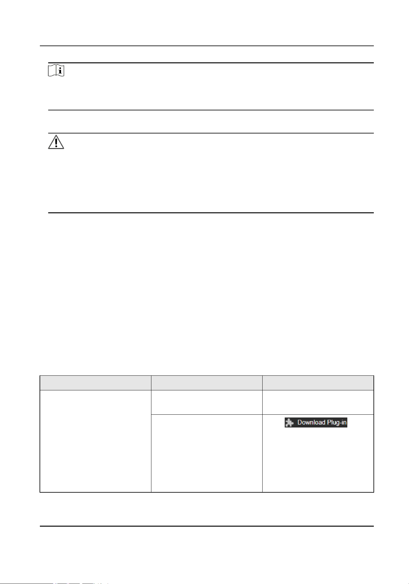
Operating System Web Browser Operation
Windows Internet Explorer 10+ Follow pop-up prompts to
complete plug-in installation.
Google Chrome 57+
Mozilla Firefox 52+
Click
to
download and install plug-in.
Go to Conguration >
Network > Advanced
Settings > Network Service
to enable WebSocket or
WebSockets for normal view
Thermal & Optical Bi-spectrum PTZ Network Camera User Manual
3

Operating System Web Browser Operation
if plug-in installation is not
required. Display and
operation of certain
functions are restricted. For
example, Playback and
Picture are not available. For
detailed restricted function,
refer to the actual device.
Mac OS 10.13+ Mac Safari 12+ Plug-in installation is not
required.
Go to Conguration >
Network > Advanced
Settings > Network Service
to enable WebSocket or
WebSockets for normal
view. Display and operation
of certain functions are
restricted. For example,
Playback and Picture are not
available. For detailed
restricted function, refer to
the actual device.
Note
The device only supports Windows and Mac OS system and does not support Linux
system.
2.3.2 Illegal Login Lock
It helps to improve the security when accessing the device via Internet.
Go to
Conguration > System > Security > Security Service , and enable Enable Illegal Login
Lock, Illegal Login Attempts and Locking Duration are congurable.
Illegal Login Attempts
When your login attempts with the wrong password reach the set times, the device is
locked.
Locking Duration
The device releases the lock after the setting duration.
Thermal & Optical Bi-spectrum PTZ Network Camera User Manual
4

Chapter 3 Temperature Measurement
When you enable this function, the device measures the actual temperature of the scene. It
alarms when temperature exceeds the temperature threshold value.
Note
The function varies according to different camera models.
3.1 Notice
This part introduces the notices of conguring temperature measurement function.
●
The target surface should be as vertical to the optical axis as possible. It is
recommended that the angle of oblique image plane should be less than 45°.
●
The target image pixels should be more than 5 × 5.
●
If multiple presets will be taken for temperature measurement, it is recommended to set
the patrol time above 20 s.
●
Please select line thermography or area thermography for a certain area temperature
measurement. The point thermography is not recommended in case of deviation
occurred during device movement to affect the accuracy of temperature measurement.
3.2 Thermography Conguration Flow Chart
This part introduces the process of conguring temperature measurement.
Thermal & Optical Bi-spectrum PTZ Network Camera User Manual
5
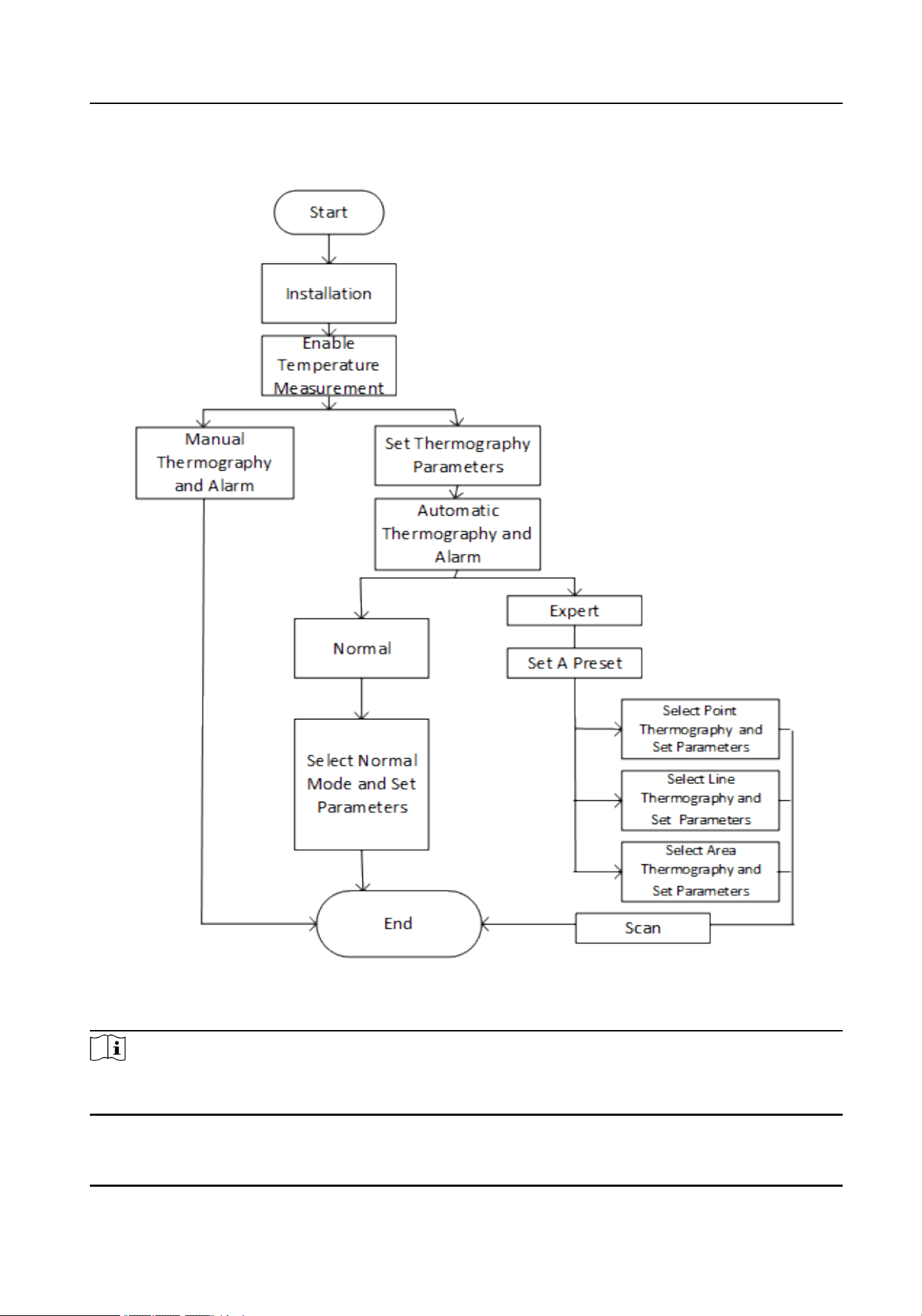
Figure 3-1 Thermography Conguration Flow Chart
Note
Please refer to the
Quick Start Guide
for detailed information of Installation part in the ow
chart.
Thermal & Optical Bi-spectrum PTZ Network Camera User Manual
6

3.3 Automatic Thermography
Congure the temperature measurement parameters and temperature measurement rules.
The device can measure the actual temperature and output alarms when temperature
exceeds the alarm threshold value.
3.3.1 Set Thermography Parameters
Congure the parameters of temperature measurement.
Steps
1.
Go to Conguration > Local , enable Display Temperature Info.
Display Temperature Info.
Select Yes to display temperature information on live view.
Enable Rules to display the rules information on live view.
2.
Click Save.
3.
Go to Conguration > Temperature Measurement > Basic Settings to congure
parameters.
Enable Temperature Measurement
Check to enable temperature measurement function.
Enable Color-Temperature
Check to display Temperature-Color Ruler in live view.
Display Temperature Info. on Stream
Check to display temperature information on the stream.
Display Temperature in Optical Channel
Check to display thermal channel temperature information in the optical channel.
Display Max./Min./Average Temperature
Check to display maximum/minimum/average temperature information on live view
when the temperature measurement rule is line or area.
Rule Name
Display the rule name rather than the rule ID on the live view. You can set the name in
expert temperature measurement mode for the rule.
Position of Thermometry Info
Select the position of temperature information showed on the live view.
●
Near Target: Display the information beside the temperature measurement rule.
●
Top Left: Display the information on the top left of screen.
Add Original Data on Capture
Check to add data on alarm triggered capture of thermal channel.
Thermal & Optical Bi-spectrum PTZ Network Camera User Manual
7

Add Original Data on Stream
Add and save original raw data to stream. The function requires higher network
bandwidth.
Data Refresh Interval
It means the refresh interval of original data.
Display Pixel-to-Pixel Thermometry Data on Stream
Add and save real-time pixel-to-pixel thermometry data to stream. The function
requires higher network bandwidth.
The function varies according to different camera models.
Pixel-to-Pixel Thermometry Data Refresh Interval
It means the refresh interval of thermometry data.
Unit
Display temperature with Degree Celsius (°C)/Degree Fahrenheit (°F)/Degree Kelvin
(K).
Temperature Range
Select the temperature measurement range. The device can adjust the temperature
range automatically if you select Auto.
Atmospheric Temperature
Set the atmospheric temperature.
Atmospheric Humidity
Set the atmospheric humidity.
Atmospheric Transmissivity
Set the atmospheric transmissivity from 0 to 1.
Distance Mode
Select the distance mode for temperature measurement. Fixed Distance and Self-
Adaption are selectable.
Version
View the version of current algorithm.
Calibration File Version
View the version of calibration le.
Alarm Interval
Set the alarm interval between two alarms.
Reect Light Filter
Enable these functions if there is strong reected light from sun, or it may cause false
alarm. The lter sensitivity can be adjusted.
Thermal & Optical Bi-spectrum PTZ Network Camera User Manual
8

Check Display Filtering Status, and the OSD will be displayed when the function is
enabled.
Click Restart to restart the algorithm library of reect light lter.
The Reect Light Filter function varies according to different camera models.
Forklift Filter
Enable these functions if there is forklift in the scene, or it may cause false alarm. The
lter level can be adjusted.
Check Display Filtering Status, and an OSD will be displayed when the function is
enabled.
Set Filtering Temperature, e.g., set the ltering temperature as 300 °C and forklifts
can be ltered only when their temperature is lower than 300 °C. The function varies
according to different camera models.
Click Restart to restart algorithm library of forklift lter.
Note
Forklift Filter is mutually exclusive with VCA, Ship Detection and Fire and Smoke
Detection.
4.
Click Save.
3.3.2 Set Normal Mode
This function is used to measure the temperature of the whole scene and alarm.
Steps
1.
Check Enable Temperature Measurement.
2.
Refer to
Set Thermography Parameters
to set the parameters.
3.
Go to Conguration > Temperature Measurement & Fire Prevention > Advanced
Settings , and select Normal.
4.
Congure the parameters of normal mode.
Emissivity
Set the emissivity of your target. The emissivity of each object is different.
Distance
The distance between the target and the device.
Pre-Alarm Threshold
When the temperature of target exceeds the pre-alarm threshold, and this status
keeps more than
Filtering Time, it triggers pre-alarm.
Alarm Threshold
When the temperature of target exceeds the alarm threshold, and this status keeps
more than Filtering Time, it triggers alarm.
Thermal & Optical Bi-spectrum PTZ Network Camera User Manual
9

Pre-Alarm Output and Alarm Output
Check Pre-Alarm Output and Alarm Output to link the pre-alarm or alarm with the
connected alarm device.
5.
Refer to
Set Arming Schedule
for setting scheduled time. Refer to
Linkage Method
Settings
for setting linkage method.
6.
Click Save.
The maximum and minimum temperature will be displayed on the live view.
Note
Go to Image > VCA Rules Display to adjust the font size and the temperature color of
normal, alarm and pre-alarm.
3.3.3 Set Expert Mode
Select the temperature measurement rules from Point, Line, or Area and congure
parameters, the device alarms if the alarm rules are met.
Steps
1.
Go to Conguration > Temperature Measurement > Basic Settings , check Enable
Temperature Measurement.
2.
Refer to
Set Thermography Parameters
to set the parameters.
3.
Go to Conguration > Temperature Measurement > Advanced Settings , select Expert.
4.
Refer to
Set Preset
to set a preset.
5.
Select and enable the temperature measurement rules. Please refer to
Set
Thermography Rule
for setting the rule.
6.
Optional: Click Area's Temperature Comparison to set the alarm rules and the
temperature.
7.
Refer to
Set Arming Schedule
for setting scheduled time. Refer to
Linkage Method
Settings
for setting linkage method.
8.
Click Save.
The maximum temperature and thermography rules will be displayed on the live view.
Note
Go to Image > VCA Rules Display to adjust the font size and the temperature color of
normal, alarm and pre-alarm.
9.
Optional: Call the preset and check if the rules are efcient.
10.
Enable the scan function of device, such as linear scan to monitor the scene.
3.3.4 Set Thermography Rule
Steps
1.
Customize the rule name.
Thermal & Optical Bi-spectrum PTZ Network Camera User Manual
10

2.
Select the rule type to Point, Line, or Area. Then draw a point, line, or area on the
interface where the position to be measured.
Point Please refer to
Point Thermography
for detailed conguration.
Line Please refer to
Line Thermography
for detailed conguration.
Area Please refer to
Area Thermography
for detailed conguration.
3.
Congure the temperature measurement parameters.
Emissivity
Set the emissivity of the target. The emissivity of the surface of a material is its
effectiveness in emitting energy as thermal radiation. Different objects have different
emissivity. Refer to
Common Material Emissivity Reference
to search for the target
emissivity.
Distance
The distance between the target and the device.
Reective Temperature
If there is any object with high emissivity in the scene, check and set the reective
temperature to correct the temperature. The reective temperature should be set the
same as the temperature of the high emissivity object.
4.
Click and set the Alarm Rule.
Alarm Temperature and Pre-Alarm Temperature
Set the alarm temperature and pre-alarm temperature. E.g., select Alarm Rule as
Above (Average Temperature), set the Pre-Alarm Temperature to 50 °C, and set the
Alarm Temperature to 55 °C. The device pre-alarms when its average temperature is
higher than 50 °C and alarms when its average temperature is higher than 55 °C.
Filtering Time
It refers to the duration time after the target temperature reaches or exceeds the pre-
alarm temperature/alarm temperature.
Tolerance Temperature
Set the tolerance temperature to prevent the constant temperature change to affect
the alarm. E.g., set tolerance temperature as 3 °C, set alarm temperature as 55 °C, and
set pre-alarm temperature as 50 °C. The device sends pre-alarm when its temperature
reaches 50 °C and it alarms when its temperature reaches 55 °C and only when the
device temperature is lower than 52 °C will the alarm be cancelled.
Pre-Alarm Output and Alarm Output
When the temperature of target exceeds the pre-alarm or alarm threshold, it triggers
the pre-alarm or alarm output of the connected device.
Area's Temperature Comparison
Thermal & Optical Bi-spectrum PTZ Network Camera User Manual
11

Select two areas and set the comparison rule, and set the temperature difference
threshold. The device alarms when the temperature difference meets the setting
value.
5.
Refer to
Set Arming Schedule
for setting scheduled time. Refer to
Linkage Method
Settings
for setting linkage method.
6.
Optional: Shield certain area from being detected. Refer to for detailed settings.
7.
Optional: Set the offsite pre-alarm/alarm specially during off-hours when there are less
causes of false alarms. You can set the lower alarm temperature to improve the
efciency of quick alarm.
Note
The function varies according to different camera models.
1)Click .
2)Check Enable Offsite.
3)Set the offsite pre-alarm/alarm and follow step 4~5 to adjust the pre-alarm/alarm
temperature and arming schedule during working hours.
Note
The same parameters and linkage method apply to the two kinds of pre-alarm/alarm,
only the threshold temperature and arming schedule vary.
Offsite Pre-Alarm Temperature
When the temperature of target exceeds the Offsite Pre-Alarm Temperature during
the Offsite Arming Schedule, and this status lasts not shorter than the Filtering Time,
the pre-alarm is triggered.
Offsite Alarm Temperature
When the temperature of target exceeds the Offsite Alarm Temperature during the
Offsite Arming Schedule, and this status lasts not shorter than the Filtering Time, the
alarm is triggered.
Offsite Arming Schedule
Click and drag the time bar to select the arming off-hours for offsite pre-alarm and
alarm.
8.
Click Save.
Click Live View, and select thermal channel to view the temperature and rules
information on live view.
Point Thermography
Congure the temperature measurement rule and click any point in live view to monitor the
temperature.
Thermal & Optical Bi-spectrum PTZ Network Camera User Manual
12

Steps
1.
Click in the live view and a cross cursor shows on the interface.
2.
Drag the cross cursor to desired position.
Go to Live View interface to view the temperature and rule of the point in thermal
channel.
Line Thermography
Congure the temperature measurement rule and monitor the maximum temperature of
the line.
Steps
1.
Click and drag the mouse to draw a line in the live view interface.
2.
Click and move the line to adjust the position.
3.
Click and drag the ends of the line to adjust the length.
Go to Live View interface to view the maximum temperature and rule of the line in
thermal channel.
Area Thermography
Congure the temperature measurement rule and monitor the maximum temperature of
the area.
Steps
1.
Click and drag the mouse in the live view to draw the area and right click to nish
drawing.
2.
Click and move the area to adjust the position.
3.
Drag the corners of the area to adjust the size and shape.
Go to Live View interface to view the maximum temperature and rule of the area in
thermal channel.
3.4 Manual Thermography
After enable the manual thermography function of the device, you can click any position on
the live view to show the real temperature.
Steps
1.
Go to Conguration > Local and select Display Temperature Info. as Yes.
2.
Go to Conguration > Temperature Measurement & Fire Prevention > Basic Settings .
3.
Check Enable Temperature Measurement.
4.
Click Save.
Thermal & Optical Bi-spectrum PTZ Network Camera User Manual
13

5.
Go to live view interface and select thermal channel, click . Click any position on the
interface to show the real temperature.
3.5 Search History Temperature
You can search the history temperature and generate the temperature/time graphic.
Before You Start
Refer to
Set Memory Card
and
Set NAS
to set the storage rst.
Steps
1.
Go to Conguration > Temperature Measurement > Search History Temperature .
2.
Set the search parameters.
Preset
You can search the highest temperature information in normal mode. Or you can
search the temperature information of special presets in expert mode.
Rule
Select a rule of the special preset.
Start Time
Set the searching start time.
Display Time Interval
Display the temperature information for every setting time interval.
3.
Click Search to generate the graphic.
4.
Click Export to download the graphic.
Thermal & Optical Bi-spectrum PTZ Network Camera User Manual
14

Chapter 4 Fire and Smoke Detection
The device will trigger and upload alarm when detect the re source or smoke.
Fire and smoke detection is applied to re-prevention purposes in scenic region, forest,
tunnel and so on. You can congure the re source detection parameters and smoke
detection parameters. When re source or smoke is detected, the alarm actions will be
triggered.
Note
Not all models support the smoke detection function, take the actual product for
reference.
4.1 Fire and Smoke Detection Flow Chart
Introduce the process of conguring re and smoke detection.
Thermal & Optical Bi-spectrum PTZ Network Camera User Manual
15
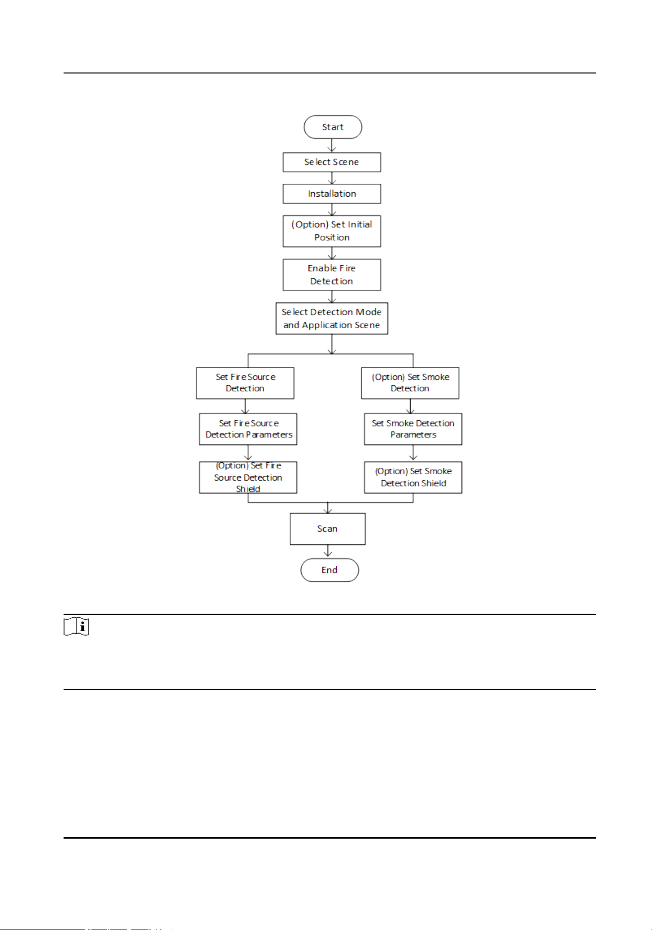
Figure 4-1 Fire and Smoke Detection Flow Chart
Note
Please refer to the Quick Start Guide for detail information of Installation part in the ow
chart. Obtain the information of longitude, altitude, direction and so on by device after
installation.
4.2 Recommended Scene
This part introduces the recommended scenes of re source detection and helps you
select the appropriate scene.
Thermal & Optical Bi-spectrum PTZ Network Camera User Manual
16

Fire source detection can be applied to indoor and outdoor monitoring with a large
detection radius. To achieve the best monitoring effect, please set the installation place as
requirements below.
●
The installation place should be the highest position within the detection area. The lens
should not be covered during movement to detect the maximum area.
●
It is better to choose the installation place with convenient trafc, well-equipped power
and internet facilities (e.g., communication tower, watchtower and high-rise roof).
4.3 Detection Mode and Application Scene
Fire and Smoke Detection Mode
Fire or Smoke
The system alarms when device is either triggered by re source detection or smoke
detection.
Fire and Smoke
The system holds when device is triggered by re source detection or smoke detection.
When target is detected by both rules, the system sends two alarms, otherwise, the
system sends single alarm.
Double Conrm
The system alarms when device is both triggered by re source detection and smoke
detection.
Specied Fire Source
The system alarms when device is triggered by re source detection.
Specied Smoke
The system alarms when device is triggered by smoke.
Application Scene
In Application Scene, Short Distance and Long Distance are selectable. Select the scene
according to the actual distance.
4.4 Set the Presets
Please set the presets according to steps below to improve the accuracy of re detection.
Steps
1.
If the presets located in different areas, you can set 6 presets in two areas as the
example showed below.
Thermal & Optical Bi-spectrum PTZ Network Camera User Manual
17
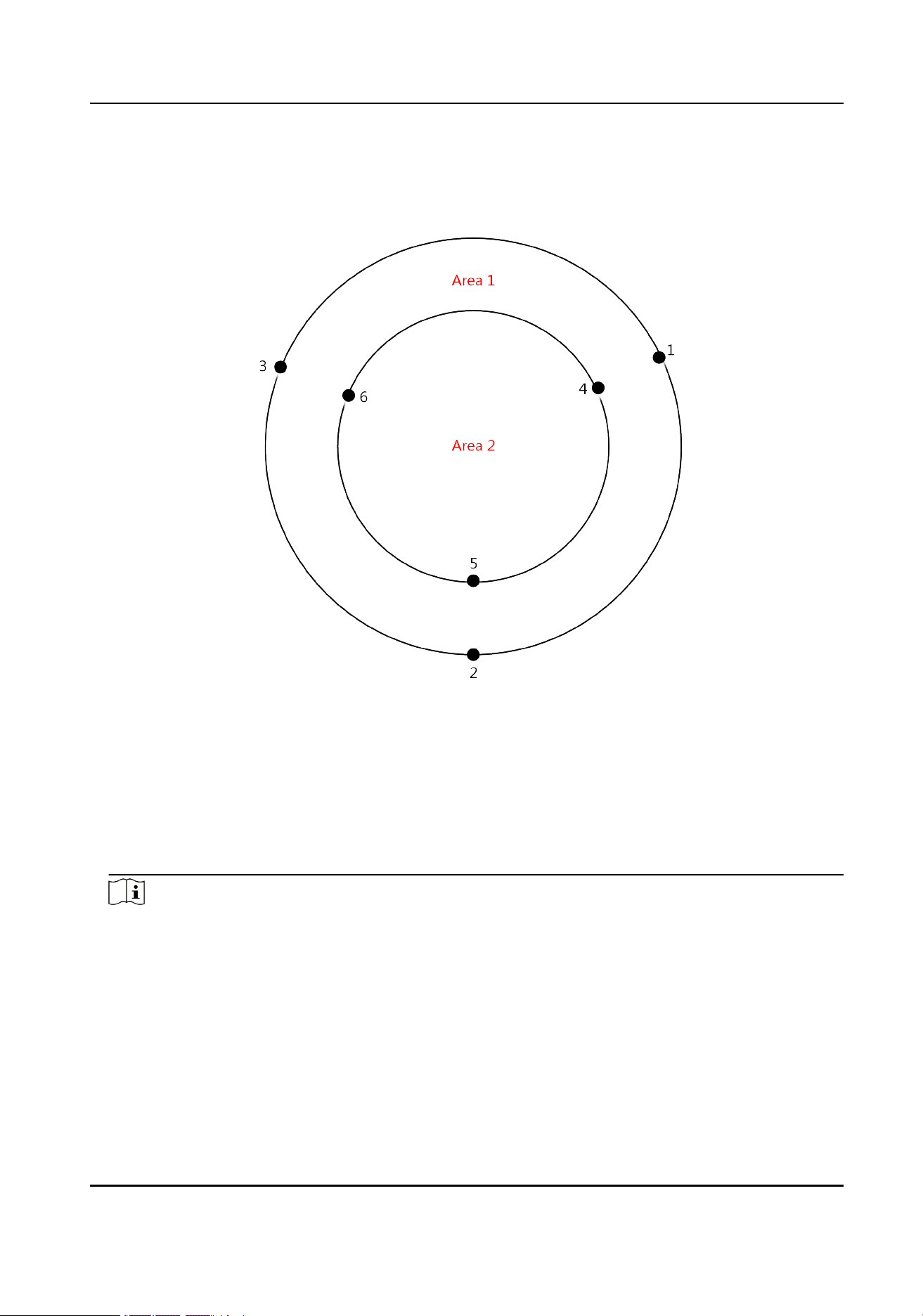
Figure 4-2 Set the Presets for re detection
2.
Divide the scan area into three parts and set a preset every 120°. The black numbers are
presets, and the red numbers are scan areas.
3.
Set the presets according to the sequence of patrol path: 1->2->3->1->4->5->6->4.
Note
●
When set the presets, you should adjust the zoom ratio to view the image of both
optical channel and thermal channel clearly.
●
The recommended zoom ratio of optical channel and patrol speed shows in the table
below.
Thermal & Optical Bi-spectrum PTZ Network Camera User Manual
18

16.7-1000
(focus
distance)
12.5-775
(focus
distance)
15.6-500
(focus
distance)
6.7-330
(focus
distance)
10-320
(focus
distance)
6-240
(focus
distance)
The left column is optical ratio, the right columns are speed level.
15
km
15 4 20 4 / / / / / / / /
10
km
10 5 15 4 12 4 / / / / / /
5 km 7 6 10 5 8 5 20 4 13 4 / /
3 to
5 km
5 6 7 6 6 6 13 4 9 5 15 4
4.5 Set Fire Detection Parameters
To avoid the potential re damage, you should congure the re detection function for
certain areas. The detail conguration steps show as below.
Before You Start
●
The re detection function can locate the re source area quickly together with patrol or
linear scan. Please refer to
Set Patrol Scan
for conguring patrol. Please refer to
Set the
Presets
for presets setting.
●
Please refer to
Set Device Position
for locating the re source position.
●
Go to Conguration > Local , set the re point parameters.
Locate Highest Temperature Point
Click and save to show the position of the highest temperature on the interface.
Frame Fire Point
Click and save to frame the detected re source.
Steps
1.
Go to Conguration > Event > Smart Event , select Fire and Smoke Detection.
2.
Check Enable Fire and Smoke Detection.
3.
Refer to
Detection Mode and Application Scene
for setting the re detection mode.
4.
Check Display Fire Source Frame on Stream to display a red frame around the re source
on stream when re occurs.
5.
Setting the parameters of re detection.
Detection Mode
by Single Frame
It can quickly detect re while moving, but have a high false positive rate.
Thermal & Optical Bi-spectrum PTZ Network Camera User Manual
19

Adjust Sensitivity during Patrol. The bigger the value is, the more easily the re
source can be detected, and the false rate is higher.
by Multiple Frame
The system stops to check the doubtful re source after rst detection. It alarms
with high accuracy after double checking the re source on multiple frames, thus the
detection speed is slow.
As to the detection sensitivity of this mode, adjust the Sensitivity during Patrol for
the rst detection and Verication Sensitivity for the double check.
In this detection mode, Smoke Auxiliary Detection can also be used to help verify the
re source.
Check Cancel Repeated Alarm and the device alarms only one time if re source
detected in the same place during one day.
Smoke Auxiliary Detection
The device conducts smoke detection to verify the re source. It can be congured
when the detection mode is selected as by Multiple Frame.
Cancel Repeated Alarm
Alarm only one time if re source detected in the same place. It can be congured
when the detection mode is selected as by Multiple Frame.
Sensitivity
The sensitivity of re detection. The bigger the value is, more easily the re source
can be detected, and the false rate is higher.
Hold-and-Alarm Mode
Auto and Manual are selectable. The system will stop when it detects the re source.
You can set the duration while it keeps still.
Auto
You can set the dwell time. During the dwell time the camera stays still where it
detects the re source when performing auto scan, patrol, pattern, scheduled task,
and park action.
Manual
The device stays still where it detects the re source, until you manually
Fire Source Zoom Ratio
Auto
The optical channel changes its zoom ratio until the thermal channel has the same
eld of view.
Manual
You can set the optical zoom ratio.
Thermal & Optical Bi-spectrum PTZ Network Camera User Manual
20

Note
The settings vary according to different models.
6.
Optional: You can shield certain areas from being detected in re source detection. Refer
to
Set Fire Source Shielded Region
for details.
7.
Refer to
Set Arming Schedule
for setting scheduled time. Refer to
Linkage Method
Settings
for setting linkage method.
8.
Click Save.
4.5.1 Set Fire Source Shielded Region
Steps
1.
Go to Conguration > Local , and enable Display Shield Area.
2.
Go to Conguration > Event > Smart Event > Fire Source Region Shield .
3.
Check Enable Fire Source Detection Shield.
4.
Select Drawing Mode, and draw the area you want to shield.
In FOV Select this mode if the shielded area is in the current scene.
a. Click the PTZ control buttons to nd the area you want to shield from
the re detection.
b. Click Draw Area, and drag the mouse in the live view to draw the area.
c. You can drag the corners of the red rectangle area to change its
shape and size.
d. Click Stop Drawing to nish drawing, or click Clear All to clear all of
the areas you set without saving them.
Out FOV Select this mode if the shielded area exceeds the current scene.
a. Click Draw Area, and a red cursor displays in live view.
b. Select Vertex NO. 1, and adjust the live view image by clicking the
PTZ control buttons.
c. When one corner of the shielded area is on the red cursor, click Set
Vertex.
d. Repeat steps b-c to set other three vertexes.
e. Click Stop Drawing to nish drawing, or click Clear All to clear all of
the vertexes you set.
In
Panorama
Map
Select this mode if you want to view the whole scene.
a. Click Draw Area and drag the mouse in the live video window to draw
the area.
b. Drag the corners of the red rectangle area to change its shape and
size.
c. Click Stop Drawing to nish drawing or click Clear All to clear all of
the areas you set without saving them.
d. Click to regenerate the panorama map.
Thermal & Optical Bi-spectrum PTZ Network Camera User Manual
21

Note
●
Set vertexes clockwise or anticlockwise in sequence.
●
The pan angle of set area should be from 2 to 80 degrees, and tilt angle should be
from 1 to 45 degrees.
●
Draw four vertexes again if you want to change the shielded area.
●
When you select In Panorama Map from the drop-down list but the generation of
panorama map failed, click Regenerating Panorama Map... to regenerate it.
●
In the In Panorama Map mode, the pan angle and tilt angle of the set area should be
within ± 60°.
5.
Check Display Shield Area to show the shield area on the live view.
6.
Click Add to save the re detection shield, and it will be listed in the Fire Source
Detection Shield List area; you can select a region and click Delete to delete it from the
list; you can also dene the color of the regions.
7.
Click Save.
Note
This function varies according to different camera models.
4.6 Set Smoke Detection Parameters
To avoid the potential smoke damage, you should congure the smoke detection function
for certain areas. The detail conguration steps show as below.
Steps
1.
Go to Conguration > Event > Smart Event , select Fire and Smoke Detection.
2.
Check Enable Fire and Smoke Detection.
3.
Refer to
Detection Mode and Application Scene
for setting the smoke detection mode.
4.
Check Display Smoke Info on Stream to display the smoke information on stream.
5.
Check Cancel Repeated Alarm to alarm only one time if smoke detected in the same
place.
6.
Set the Sensitivity during Patrol and Verication Sensitivity of smoke detection. The
higher the value is, the more easily the smoke can be detected, and the false alarm rate
is higher.
7.
Optional: you can shield certain areas from being detected in smoke detection.
1)Go to Conguration > Event > Smart Event > Smoke Detection Shield .
2)Check Enable Smoke Detection Shield .
3)Click Draw Area and drag the mouse in the live view to draw the area. Release the
mouse to nish drawing.
4)You can drag the corners of the red rectangle area to change its shape and size. Or
drag the rectangle to the position on your demand.
5)Click Stop Drawing.
6)Click Clear All to clear all of the setting areas.
Thermal & Optical Bi-spectrum PTZ Network Camera User Manual
22

7)Set the value of Active Zoom Ratio on your demand, and then the shield will only
appear when the zoom ratio is greater than the predened value
8)Click Add to save the smoke detection shield, and it will be listed in the Smoke
Detection Shield List area. You can select a region and click Delete to delete it from
the list. You can also dene the color of the regions.
9)Check Display Shield Region to show the shielded area in live view.
8.
Refer to
Set Arming Schedule
for setting scheduled time. Refer to
Linkage Method
Settings
for setting linkage method.
9.
Click Save.
Thermal & Optical Bi-spectrum PTZ Network Camera User Manual
23

Chapter 5 Ship Detection
In this function, you can set parameters and alarm rules for ship ow detection, dredger
detection, and shing ship detection. The camera will detect the target according to the
settings, and will alarm when the target breaks the set rules. This function varies according
to different camera models.
5.1 Set Basic Parameters for Ship Detection
Steps
1.
Go to Conguration > Ship Detection .
2.
Go to Basic Parameter to congure ship detection parameters for the device.
Enable Ship Detection
Select to enable the ship detection function.
Display Ship Info on Stream
Select to display the ship information on the stream.
Back to Scene Time
Set the time back to the detection after the detection is interrupted manually.
Device Height
Set the installation height of the device in actual applications. The installation height
is the distance from the device to the water surface.
3.
Click Save.
5.2 Set Detection Scene and Rule
You can create one or more scenes, and set parameters and rules for each scene. The
camera will track the target and alarm when the rule is triggered.
Steps
1.
Go to Conguration > Ship Detection > Scene Conguration .
2.
Click Scene Conguration and New Scene to create one or more scenes.
3.
Go to Scene x > Rule .
4.
Set rules for the selected function mode.
●
Refer to
Set Ship Flow Detection
for setting rules for ship ow detection.
●
Refer to
Set Dredger Detection
for setting rules for dredger detection.
●
Refer to
Set Fishing Ship Detection
for setting rules for shing ship detection.
5.
Refer to
Set Arming Schedule
for setting scheduled time. Refer to
Linkage Method
Settings
for setting linkage method.
Thermal & Optical Bi-spectrum PTZ Network Camera User Manual
24

5.2.1 Set a Detection Scene
Multiple detection scenes are supported for both channels. You can create scenes and set
the tracking parameters for better target monitoring performance. The settings may vary
according to different camera models.
Steps
1.
Go to Conguration > Ship Detection .
2.
Click Scene Conguration and New Scene to create one or more scenes.
3.
Select a numbered scene from the navigation bar on the left and enter a Scene Name.
Note
If you want to show the name on the image, check Display Scene Name.
4.
Select a Channel No. from the drop down list.
5.
Set the Scene Ratio by controlling the zoom in/out buttons.
6.
Check Track to enable the target tracking function for the scene.
7.
Optional: Check Limited Tracking and set the auto tracking range.
The camera channel tracks a target only within the set auto tracking range.
1)Control the PTZ buttons to a desired scene and click Set Up Limit to save the position
as the scene's upper boundary.
2)Repeat to set the left, right and lower boundaries of the scene.
Tracking Duration
Set the duration of tracking. If the value is selected as 0, the tracking duration will
not be limited.
Zooming Ratio
It is the zoomed-in level when the camera channel is tracking a target.
Go to Conguration > Ship Detection > Zooming Ratio , select a scene from the
drop-down list, and control the zoom in/out buttons to get a desired zooming level,
and save the settings.
Post-tracking
Set the duration of automatic tracking of the target after it stops.
Go to Conguration > VCA > Advanced Conguration , and set parameter.
8.
Click Save.
5.2.2 Set Ship Flow Detection
After enabling this function, the device will trigger an alarm if ships enter or exit the set
regions, and will count the ships that pass across the alarm line for the rst time.
Steps
1.
Go to Conguration > Ship Detection > Scene Conguration > Scene x > Rule .
Thermal & Optical Bi-spectrum PTZ Network Camera User Manual
25

2.
Select Ship Flow Detection from the drop-down list.
3.
Check Region Entrance/Exiting Alarm.
4.
Draw an area.
1)Click and drag the mouse in the live video window to draw the area. You can drag the
corners of the rectangle area to draw a polygon area.
2)Optional: Click Stop Drawing to nish drawing or click Clear All to clear all of the areas
you set without saving them.
3)
Click
to add alarm lines. The device will count automatically when a ship passes
across the alarm line for the rst time and triggers an alarm.
4)Click and select the alarm line to adjust its length and position. The alarm line should
be longer than the width of ship detection area.
Note
●
Avoid water areas with oating objects or aquaculture.
●
Set multiple alarm lines in wide river to improve the detection accuracy.
5.
Set the min. size and max. size of the target. When the target is smaller than the min.
size or bigger than the max. size, the device can detect the target, but no alarm will be
triggered.
6.
Click Recount to restart the counter.
7.
Click Save.
8.
Refer to
Set Arming Schedule
for setting scheduled time. Refer to
Linkage Method
Settings
for setting linkage method.
5.2.3 Set Dredger Detection
After enabling this function, the device will detect the dredgers and trigger an alarm
according to the alarm settings.
Steps
1.
Go to Conguration > Ship Detection > Scene Conguration > Scene x > Rule .
2.
Select Ship Flow Detection from the drop-down list.
3.
Set the Overstaying Alarm Time. When the staying time of a ship is longer than the set
value, the ship is identied as a dredger, and an alarm will be triggered.
4.
Set the min. size and max. size of the target. When the target is smaller or bigger than
the set sizes, the device can detect the target, but no alarm will be triggered.
5.
Optional: Check Cancel Repeated Alarm. Alarms will not be repeatedly triggered when
the ships are in the same scene and at the same coordinates, and the size difference of
the ships is within certain value.
6.
Click Draw Area. Click and drag the mouse in the live video window to draw the area. You
can drag the corners of the rectangle area to draw a polygon area.
7.
Optional: Click Stop Drawing to nish drawing or click Clear All to clear all of the areas
you set without saving them.
8.
Click Save.
Thermal & Optical Bi-spectrum PTZ Network Camera User Manual
26

9.
Refer to
Set Arming Schedule
for setting scheduled time. Refer to
Linkage Method
Settings
for setting linkage method.
5.2.4 Set Fishing Ship Detection
After enabling this funtion, the device will detect shing ships and trigger an alarm
according to the alarm settings.
Steps
1.
Go to Conguration > Ship Detection > Scene Conguration > Scene x > Rule .
2.
Select Fishing Ship Detection from the drop-down list.
3.
Set the min. size and the max. size of the target. When the target is smaller than the min.
size or bigger than the max. size, the device can detect the target, but no alarm will be
triggered.
4.
Set the min. speed and the max. speed of the target. When the target speed is less than
the min. speed or greater than the max. speed, the device can detect the target, but no
alarm will be triggered.
5.
Click Draw Area. Click and drag the mouse in the live video window to draw the area. You
can drag the corners of the rectangle area to draw a polygon area.
6.
Optional: Click Stop Drawing to nish drawing or click Clear All to clear all of the areas
you set without saving them.
7.
Click Save.
8.
Refer to
Set Arming Schedule
for setting scheduled time. Refer to
Linkage Method
Settings
for setting linkage method.
5.2.5 Set Capture Ratio
After enabling this function, ship-centered captures with the set capture ratio will be
uploaded when a ship detection alarm is triggered.
Steps
1.
Go to Conguration > Ship Detection > Scene Conguration .
2.
Select a scene.
3.
Check Enable Center Capture.
4.
Set Capture Ratio and Centering Dwell Time.
Capture Ratio
Set the ratio of the captured image by controlling the zoom in/out buttons.
Centering Dwell Time
The duration of the current status after the center capture.
5.
Click Save.
Thermal & Optical Bi-spectrum PTZ Network Camera User Manual
27

Note
This function is invalid when the tracking function is enabled.
5.3 Set Scene Auto-Switch
The device supports patrol among the scenes and performs the set detection. Patrol
sequence and dwelling time in each scene are congurable.
Before You Start
Finish scene settings in advance. See
Set a Detection Scene
for conguration instructions.
Steps
1.
Go to Ship Detection > Scene Auto-Switch to congure this function.
2.
Set the scene patrol sequence.
Scene Name
Select a scene name from the drop down list.
Dwell Time
Set the dwell time of the scene when doing patrol tracking.
Overstaying Alarm Time
Set the overstaying alarm time of the scene when doing patrol tracking.
3.
Click the up, down arrow to adjust the patrol sequence.
4.
Click Save.
5.4 Advanced Parameters
Go to
Conguration > Ship Detection > Advanced Settings and congure the parameters.
Detection Parameters
Object Detection Threshold
The higher the value is set, the more easily the target will be detected.
Generation Speed
The higher the value is set, the faster the target generation speed will be.
Restore Parameters
Restore Default
Click Restore to restore the parameters to the default values.
Restart Algorithm Library
Click Restart to restart the Algorithm Library.
Thermal & Optical Bi-spectrum PTZ Network Camera User Manual
28

Note
The settings vary according to different models.
Thermal & Optical Bi-spectrum PTZ Network Camera User Manual
29
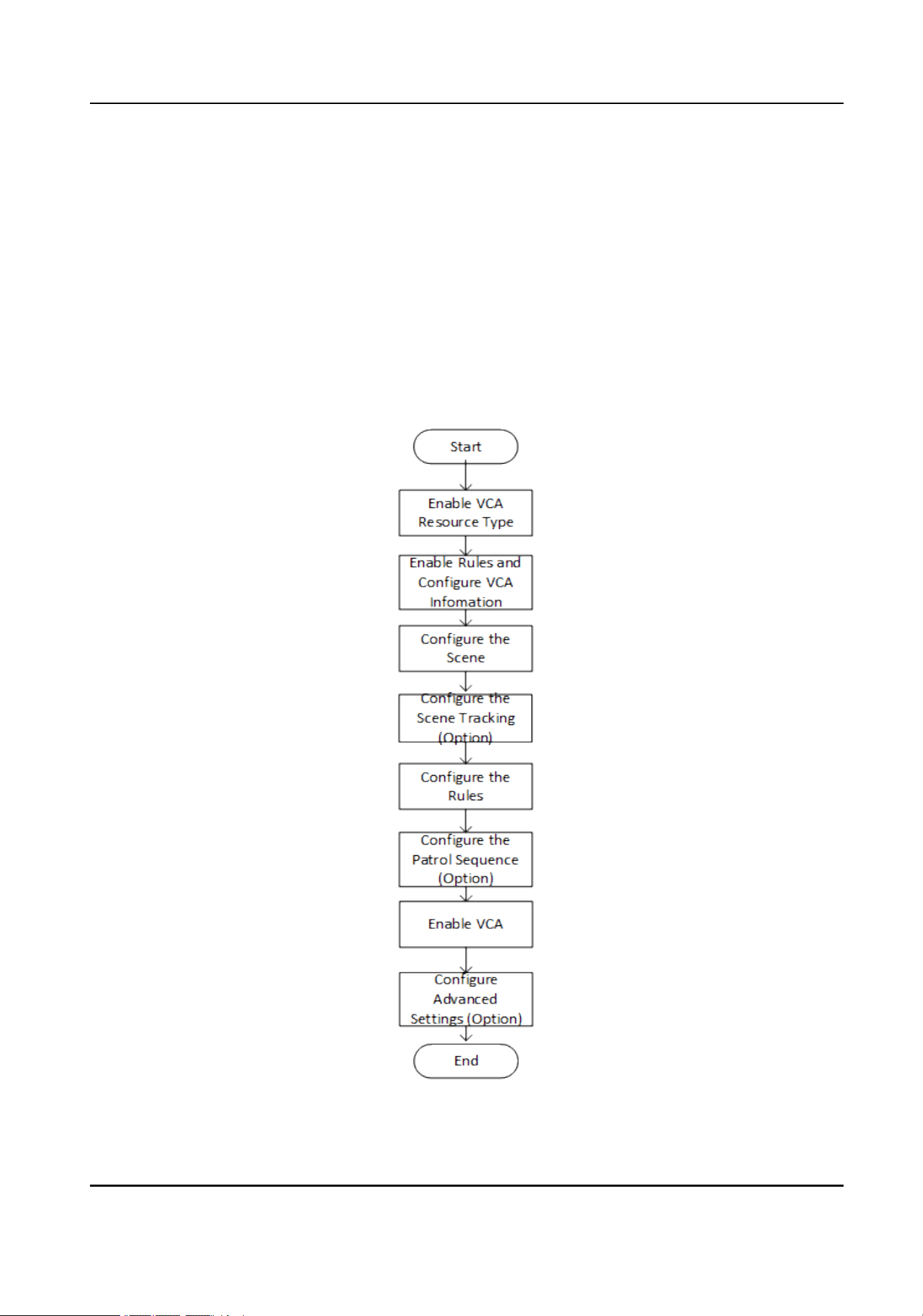
Chapter 6 Perimeter Protection
The function is used to detect whether there is any target breaking the perimeter
protection rules. The optical camera will track the target and the device will alarm when the
perimeter protection rule is triggered.
6.1 Flow Chart of Perimeter Protection
The process of conguring the perimeter protection function is described below.
Figure 6-1 Flow Chart of Perimeter Protection Conguration
Thermal & Optical Bi-spectrum PTZ Network Camera User Manual
30

6.2 Set VCA Parameters
Steps
1.
Go to Conguration > Local .
Rules
Enable it to display rules information on live view.
Display Rules Info. on Capture
Select Yes to display rules information on the capture.
2.
Go to Conguration > VCA .
3.
Select the camera channel.
4.
Go to Basic Settings to congure VCA parameters for the channel.
Display VCA Info. on Stream
Select to display target info and rule on stream, the information will be added to the
video stream, and the overlay will be displayed if you get live view or play back by the
VS Player.
Display Target Info. on Alarm Picture
Select to display the target information on the alarm picture.
Display Rule Info. on Alarm Picture
Select to display the rule information on the alarm picture.
Snapshot Settings
Select to upload the picture to the surveillance center when the VCA alarm occurs.
You can also set the quality of the picture.
5.
Click Save.
6.3 Congure the Perimeter Protection
This section is the detailed instruction of conguring the perimeter protection rules.
Steps
1.
Go to Conguration > VCA , and select a camera channel to start conguration.
2.
Refer to
Set Detection Scenes and Tracking
for detection scene and tracking settings.
3.
Refer to
Set Rules
to set the scene rules.
4.
Refer to
Set the Scene Auto-Switch
for setting scene patrol.
5.
Go to Conguration > VCA > Camera 02 > Basic Settings , enable Intelligent Analysis.
6.
Click Save.
Thermal & Optical Bi-spectrum PTZ Network Camera User Manual
31

6.3.1 Set Detection Scenes and Tracking
Multiple detection scenes are supported for both channels. You can create scenes and set
the tracking parameters for better target monitoring performance.
Steps
1.
Go to Conguration > VCA , and select a camera channel.
2.
Click Scene Conguration and New Scene to create one or more scenes.
3.
Select a numbered scene from the navigation bar on the left and enter a Scene Name.
Note
If you want to show the name on the image, check Display Scene Name.
4.
Select the type of the scene.
Note
The congured rules in current scene will be cleared if you modify the type.
5.
Check Track to enable the target tracking function for the scene.
6.
Optional: Check Limited Tracking and set the auto tracking range.
The camera channel tracks a target only within the set auto tracking range.
1)Control the PTZ buttons to a desired scene and click
Set Up Limit to save the position
as the scene's upper boundary.
2)Repeat to set the left, right and lower boundaries of the scene.
7.
Set other tracking parameters.
Tracking Duration
Set the duration of tracking. If the value is selected as 0, the tracking duration will not
be limited.
Zooming Ratio
It is the zoomed-in level when the camera channel is tracking a target.
Go to Conguration > VCA > Zooming Ratio , select a scene from the drop-down list,
and control the zoom in/out buttons to get a desired zooming level, and save the
settings.
Post-tracking
Set the duration of automatic tracking of the target after it stops.
Go to Conguration > VCA > Advanced Conguration , and set parameter.
8.
Click Save.
6.3.2 Set Rules
The device can detect whether there is any target breaking the VCA rules. The optical
camera will track the target or the device will alarm when the VCA rule is triggered.
Thermal & Optical Bi-spectrum PTZ Network Camera User Manual
32

Steps
1.
Go to Conguration > VCA > Scene Conguration > Scene x > Rule .
2.
Click to add a new rule.
3.
Enter the rule name, and click the drop down menu to select Rule Type.
Note
Each scene can be congured with different rule types. Up to 8 rules can be set for one
scene.
Line Crossing
If any target move across the setting line, the alarm will be triggered. You can set the
crossing direction.
Intrusion
If any target intrude into the pre-dened region longer than the set duration, the alarm
will be triggered.
Region Entrance
If any target enters the pre-dened region, the alarm will be triggered.
Region Exiting
If any target exits the pre-dened region, the alarm will be triggered.
4.
Set parameters of the rule.
-
Sensitivity
The higher the value is, the more easily the alarm can be triggered.
Target Detection
You are recommended to select the target as Human & Vehicle. In distant view, the
device cannot classify the target with pixels less than 10*10. The target will be
recognized as human directly. So the selection of this item will not trigger false
alarm or missing alarm.
Background Interference Suppression
Eliminate the environment interference to reduce the false alarm. For example, the
wind blows grass.
5.
Draw the rules.
-
When the rule type is selected as Line Crossing, click to draw a line in the live view.
You can drag end points of the line to adjust the position and length.
Line Crossing
You can set the crossing direction. Bidirectional, A-to-B, or B-to-A are selectable.
-
When the rule type is selected as Intrusion, Region Entrance, Region Entrance, click
to draw an area in the live view. Right click the mouse to nish drawing.
Duration
The device performs perimeter protection when the target stays in the detection
area for more than set value.
Thermal & Optical Bi-spectrum PTZ Network Camera User Manual
33

Note
Draw three segments of the rule from near to far to cover all of the detection area.
6.
Check to enable Filter by Pixel. Then Draw max size and min size rectangles to lter the
target among human, vehicle, animal, and others. Only the target whose size is between
the Max. Size and Min. Size value will trigger the alarm.
Note
●
You can draw the max. size and min. size rectangles according to the real target in the
scene. The recommended size is 1.2 times of the target.
●
The height of the rectangle is a more important factor as it is the main difference to
tell apart a human and an animal.
●
Click to copy the same settings to other rules.
7.
Click Save.
8.
Refer to
Set Arming Schedule
for setting scheduled time. Refer to
Linkage Method
Settings
for setting linkage method.
6.3.3 Set the Scene Auto-Switch
The device support patrol tracking for multiple important scenes. The alarm will be
triggered if the rule is broken during patrol sequence.
Before You Start
Finish scene settings in advance. See
Set Detection Scenes and Tracking
for conguration
instructions.
Steps
1.
Go to VCA > Scene Auto-Switch to congure this function.
2.
Set the scene patrol sequence.
Scene Name
Select a scene name from the drop down list.
Duration
Set the dwell time of the scene when doing patrol tracking.
3.
Click the up, down arrow to adjust the patrol sequence.
4.
Click Save.
6.3.4 Set Polling Plan
Both the optical channel and the thermal channels support the perimeter protection. Set
the working shift for each channel.
Before You Start
The detection scenes and rules should be congured in advance for both channels.
Thermal & Optical Bi-spectrum PTZ Network Camera User Manual
34

Steps
1.
Go to Conguration > VCA > Camera 01/Camera 02 > Basic Settings > Polling Plan .
2.
Select a polling mode.
Auto The device automatically activates the optical channel for perimeter
protection in daytime and the thermal channel at night.
Manual You can manually set the working shifts for the channels.
a. Select the Polling Mode as Manual.
b. Select Optical Channel or Thermal Channel for the drop-down list.
c. Drag to draw time bars on the schedule. Click on the drawn bar to adjust
the time and the channel.
Note
The schedule for the channels cannot overlap.
3.
Click Save.
6.4 Advanced Conguration
Go to
Conguration > VCA > Advanced Conguration and congure the parameters.
Detection Parameters
Single Alarm
The system only sends alarm once for one target triggering. Otherwise, the alarm will be
triggered continuously until the target disappears.
Tracking Parameters
Post-tracking
Set the duration of automatic tracking of the target after it stops. E.g., set post-tracking
duration to 10s, the camera tracks the target until that it stop and has been still for over
10s.
Back to Scene Time
Set the duration of the camera moving back to original scene after perimeter protection
is started.
Restore Parameters
Restore Default
Click Restore to restore the parameters to the default.
Restart VCA
Click Restart to restart the VCA function.
Thermal & Optical Bi-spectrum PTZ Network Camera User Manual
35

Note
The settings vary according to different models.
Thermal & Optical Bi-spectrum PTZ Network Camera User Manual
36

Chapter 7 Open Platform
Open platform allows you to install the application for the third-party to develop and run its
function and service.
Note
Only certain device models support the function.
7.1 Set Open Platform
You can install the application for the third-party to develop and run its function and
service. For the device supporting this function, you can follow the steps to import and run
smart applications.
Steps
1.
Go to Open Platform interface.
Note
Before installing the application, make sure that the application you want to install t the
following conditions.
●
Each application has its own exclusive name.
●
The FLASH memory space that the application takes up is less than the available
FLASH memory space of the device.
●
The memory and computing power of the application is less than that available
memory and computing power of the device.
2.
In Apps, click Import Application.
3.
Click Browse to select an application package.
4.
Click Import to import the package. You can click the APP to view relevant details.
5.
Optional: Set application.
Click Enable or disable the application.
Click Delete the application.
Click Download Logs Export log.
Click Update Browse a local path and import an
application package to update the
application.
Thermal & Optical Bi-spectrum PTZ Network Camera User Manual
37

Figure 7-1 Set VCA Resource
Thermal & Optical Bi-spectrum PTZ Network Camera User Manual
38

Chapter 8 Event and Alarm
This part introduces the conguration of events. The device takes certain response to
triggered alarm. Certain events may not be supported by certain device models.
8.1 Set Motion Detection
It helps to detect the moving objects in the detection region and trigger the linkage actions.
Steps
1.
Go to Conguration > Event > Basic Event > Motion Detection .
2.
Select the channel No.
3.
Check Enable Motion Detection.
4.
Optional: Highlight to display the moving object in the image in green.
1)Check Enable Dynamic Analysis for Motion.
2)Go to Conguration > Local .
3)Set Rules to Enable.
5.
Select Conguration Mode, and set rule region and rule parameters.
-
For the information about normal mode, see
Normal Mode
.
-
For the information about expert mode, see
Expert Mode
.
6.
Set the arming schedule and linkage methods. For the information about arming
schedule settings, see
Set Arming Schedule
. For the information about linkage
methods, see
Linkage Method Settings
.
7.
Click Save.
8.1.1 Normal Mode
You can set motion detection parameters according to the device default parameters.
Steps
1.
Select normal mode in Conguration.
2.
Set the sensitivity of normal mode. The higher the value of sensitivity is, the more
sensitive the motion detection is. If the sensitivity is set to
0
, motion detection and
dynamic analysis do not take effect.
3.
Click Draw Area. Click and drag the mouse on the live video, then release the mouse to
nsh drawing one area.
Thermal & Optical Bi-spectrum PTZ Network Camera User Manual
39
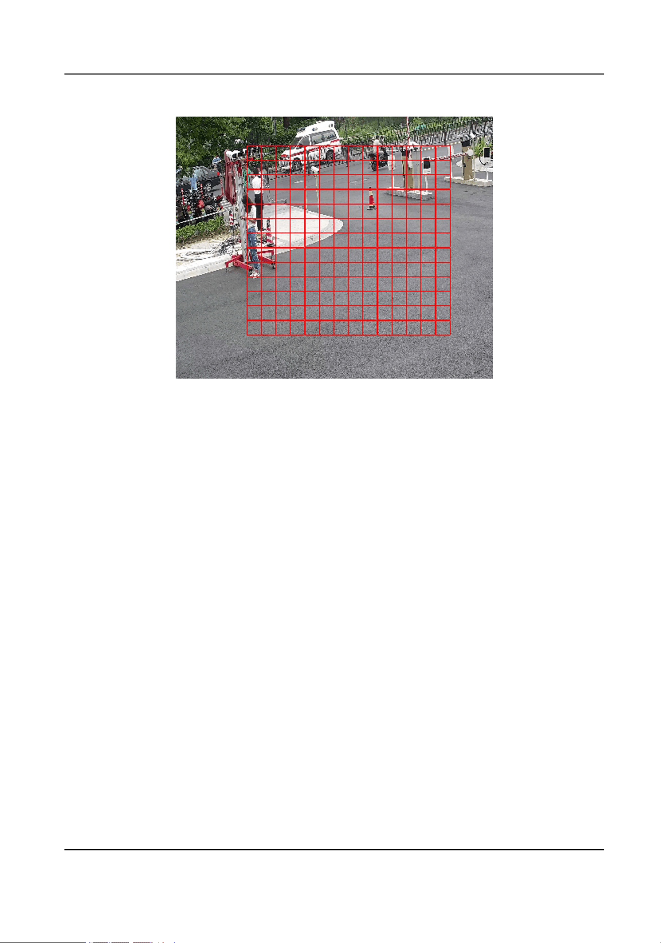
Figure 8-1 Set Rules
Stop Drawing Stop drawing one area.
Clear All Clear all the areas.
4.
Optional: You can set the parameters of multiple areas by repeating the above steps.
8.1.2 Expert Mode
You can congure the motion detection parameters of day/night switch according to the
actual needs.
Steps
1.
Select expert mode in Conguration.
2.
Set parameters of expert mode.
Day/Night Switch
OFF: Day/Night switch is disabled.
Day/Night Auto-Switch: The system switches day/night mode automatically
according to environment. It displays colored image at day and black and white image
at night.
Day/Night Scheduled-Switch: The system switches day/night mode according to the
schedule. It switches to day mode during the set periods and switches to night mode
during the other periods.
Thermal & Optical Bi-spectrum PTZ Network Camera User Manual
40
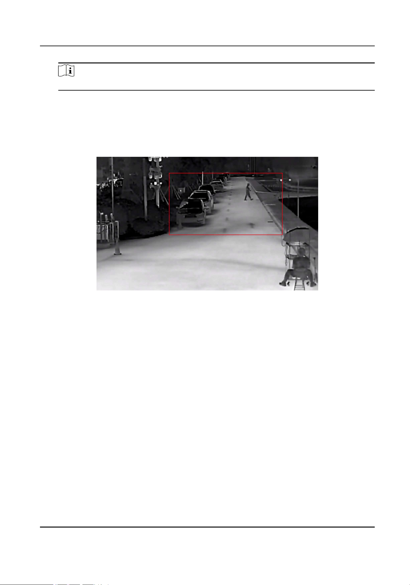
Note
This function is not supported in the expert mode of thermal channel.
Sensitivity
The higher the value of sensitivity is, the more sensitive the motion detection is. If the
sensitivity is set to
0
, motion detection and dynamic analysis do not take effect.
3.
Select an Area and click Draw Area. Click and drag the mouse on the live video, then
release the mouse to nish drawing one area.
Figure 8-2 Set Rules
Stop Drawing Finish drawing one area.
Clear All Delete all the areas.
4.
Optional: Repeat the above steps to set multiple areas.
8.2 Set Video Tampering Alarm
When the congured area is covered and cannot be monitored normally, the alarm is
triggered and the device takes certain alarm response actions.
Steps
1.
Go to Conguration > Event > Basic Event > Video Tampering .
2.
Select the channel number.
3.
Check Enable.
4.
Set the Sensitivity. The higher the value is, the easier to detect the area covering.
5.
Click Draw Area and drag the mouse in the live view to draw the area.
Stop Drawing Finish drawing.
Clear All Delete all the drawn areas.
Thermal & Optical Bi-spectrum PTZ Network Camera User Manual
41

Figure 8-3 Set Video Tampering Area
6.
Refer to
Set Arming Schedule
for setting scheduled time. Refer to
Linkage Method
Settings
for setting linkage method.
7.
Click Save.
8.3 Set Alarm Input
Alarm signal from the external device triggers the corresponding actions of the current
device.
Before You Start
Note
This function is only supported by certain models.
Make sure the external alarm device is connected. See
Quick Start Guide
for cable
connection.
Thermal & Optical Bi-spectrum PTZ Network Camera User Manual
42

Steps
1.
Go to Conguration > Event > Basic Event > Alarm Input .
2.
Check Enable Alarm Input Handling.
3.
Select Alarm Input NO. and Alarm Type from the dropdown list. Edit the Alarm Name.
4.
Refer to
Set Arming Schedule
for setting scheduled time. Refer to
Linkage Method
Settings
for setting linkage method.
5.
Click Copy to... to copy the settings to other alarm input channels.
6.
Click Save.
8.4 Set Exception Alarm
Exception such as network disconnection can trigger the device to take corresponding
action.
Steps
1.
Go to Conguration > Event > Basic Event > Exception .
2.
Select Exception Type.
HDD Full The HDD storage is full.
HDD Error Error occurs in HDD.
Network Disconnected The device is ofine.
IP Address Conicted The IP address of current device is same as that of other
device in the network.
Illegal Login Incorrect user name or password is entered.
Voltage Instable The power supply voltage is uctuating.
PT Locking The panning and tilting movements are stuck.
3.
Refer to
Linkage Method Settings
for setting linkage method.
4.
Click Save.
8.5 Set Burning-Prevention
This function is used to close the shutter to prevent the lens from high temperature
damage.
Steps
1.
Go to Conguration > Event > Basic Event > Burning-Prevention .
2.
Check Enable.
3.
Select burning-prevention mode.
Lens Movement
The lens move automatically to avoid high temperature damage.
Thermal & Optical Bi-spectrum PTZ Network Camera User Manual
43

Shutter Close
Make the shutter closed to block high temperature target.
Auto
The shutter will be closed automatically when detecting high temperature target.
You can set the protection duration.
Manual
The shutter is closed in the duration.You can set the shutter status to open or closed
as desired.
Auto Defocus
The lens automatically defocuses to protect the detector.
4.
Set the protection duration and protection delay.
5.
Optional: Check Burning Recovery to recover the live view image when the thermal
detector is damaged by high temperature target.
6.
Click Save.
8.6 Detect Audio Exception
Audio exception detection function detects the abnormal sound in the scene, such as the
sudden increase/decrease of the sound intensity, and some certain actions can be taken
as response.
Steps
1.
Go to Conguration > Event > Smart Event > Audio Exception Detection .
2.
Select one or several audio exception detection types.
Audio Loss Detection
Detect sudden loss of audio track.
Sudden Increase of Sound Intensity Detection
Detect sudden increase of sound intensity. Sensitivity and Sound Intensity Threshold
are congurable.
Note
●
The lower the sensitivity is, the more signicant the change should be to trigger the
detection.
●
The sound intensity threshold refers to the sound intensity reference for the
detection. It is recommended to set as the average sound intensity in the
environment. The louder the environment sound, the higher the value should be.
You can adjust it according to the real environment.
Sudden Decrease of Sound Intensity Detection
Detect sudden decrease of sound intensity. Sensitivity is congurable.
Thermal & Optical Bi-spectrum PTZ Network Camera User Manual
44


Chapter 9 Arming Schedule and Alarm Linkage
Arming schedule is a customized time period in which the device performs certain tasks.
Alarm linkage is the response to the detected certain incident or target during the
scheduled time.
9.1 Set Arming Schedule
Set the valid time of the device tasks.
Steps
1.
Click Arming Schedule.
2.
Drag the time bar to draw desired valid time.
Note
Up to 8 periods can be congured for one day.
3.
Adjust the time period.
-
Click on the selected time period, and enter the desired value. Click Save.
-
Click on the selected time period. Drag the both ends to adjust the time period.
-
Click on the selected time period, and drag it on the time bar.
4.
Optional: Click Copy to... to copy the same settings to other days.
5.
Click Save.
9.2 Linkage Method Settings
You can enable the linkage functions when an event or alarm occurs.
9.2.1 Trigger Alarm Output
If the device has been connected to an alarm output device, and the alarm output No. has
been congured, the device sends alarm information to the connected alarm output device
when an alarm is triggered.
Steps
Note
This function is only supported by certain models.
1.
Go to Conguration > Event > Basic Event > Alarm Output .
2.
Set alarm output parameters.
Automatic Alarm For the information about the conguration, see
Automatic Alarm
.
Thermal & Optical Bi-spectrum PTZ Network Camera User Manual
46

Manual Alarm For the information about the conguration, see
Manual Alarm
.
3.
Click Save.
Manual Alarm
You can trigger an alarm output manually.
Steps
1.
Set the manual alarm parameters.
Alarm Output No.
Select the alarm output No. according to the alarm interface connected to the
external alarm device.
Alarm Name
Edit a name for the alarm output.
Delay
Select Manual.
2.
Click Manual Alarm to enable manual alarm output.
3.
Optional: Click Clear Alarm to disable manual alarm output.
Automatic Alarm
Set the automatic alarm parameters, then the device triggers an alarm output
automatically in the set arming schedule.
Steps
1.
Set automatic alarm parameters.
Alarm Output No.
Select the alarm output No. according to the alarm interface connected to the
external alarm device.
Alarm Name
Custom a name for the alarm output.
Delay
It refers to the time duration that the alarm output remains after an alarm occurs.
2.
Set the alarming schedule. For the information about the settings, see
Set Arming
Schedule
.
3.
Click Copy to… to copy the parameters to other alarm output channels.
4.
Click Save.
Thermal & Optical Bi-spectrum PTZ Network Camera User Manual
47

9.2.2 FTP/NAS/Memory Card Uploading
If you have enabled and congured the FTP/NAS/memory card uploading, the device
sends the alarm information to the FTP server, network attached storage and memory card
when an alarm is triggered.
Refer to
Set FTP
to set the FTP server.
Refer to
Set NAS
for NAS conguration.
Refer to
Set Memory Card
for memory card storage conguration.
9.2.3 Send Email
Check Send Email, and the device sends an email to the designated addresses with alarm
information when an alarm event is detected.
For email settings, refer to
Set Email
.
Set Email
When the email is congured and Send Email is enabled as a linkage method, the device
sends an email notication to all designated receivers if an alarm event is detected.
Before You Start
Set the DNS server before using the Email function. Go to
Conguration > Network > Basic
Settings > TCP/IP for DNS settings.
Steps
1.
Go to email settings page: Conguration > Network > Advanced Settings > Email .
2.
Set email parameters.
1)Input the sender's email information, including the Sender's Address, SMTP Server,
and SMTP Port.
2)Optional: If your email server requires authentication, check Authentication and input
your user name and password to log in to the server.
3)Set the E-mail Encryption.
●
When you select SSL or TLS, and disable STARTTLS, emails are sent after encrypted
by SSL or TLS. The SMTP port should be set as 465.
●
When you select SSL or TLS and Enable STARTTLS, emails are sent after encrypted
by STARTTLS, and the SMTP port should be set as 25.
Note
If you want to use STARTTLS, make sure that the protocol is supported by your
email server. If you check the Enable STARTTLS while the protocol is not supported
by your email sever, your email is sent with no encryption.
Thermal & Optical Bi-spectrum PTZ Network Camera User Manual
48

4)Optional: If you want to receive notication with alarm pictures, check Attached
Image. The notication email has 3 attached alarm pictures about the event with
congurable image capturing interval.
5)Input the receiver's information, including the receiver's name and address.
6)Click Test to see if the function is well congured.
3.
Click Save.
9.2.4 Notify Surveillance Center
Check
Notify Surveillance Center, the alarm information is uploaded to the surveillance
center when an alarm event is detected.
9.2.5 Trigger Recording
Check
Trigger Recording, and the device records the video about the detected alarm event.
For device with more than one camera channels, you can set one or more channels to take
recordings if needed.
For recording settings, refer to
Video Recording and Picture Capture
.
Thermal & Optical Bi-spectrum PTZ Network Camera User Manual
49
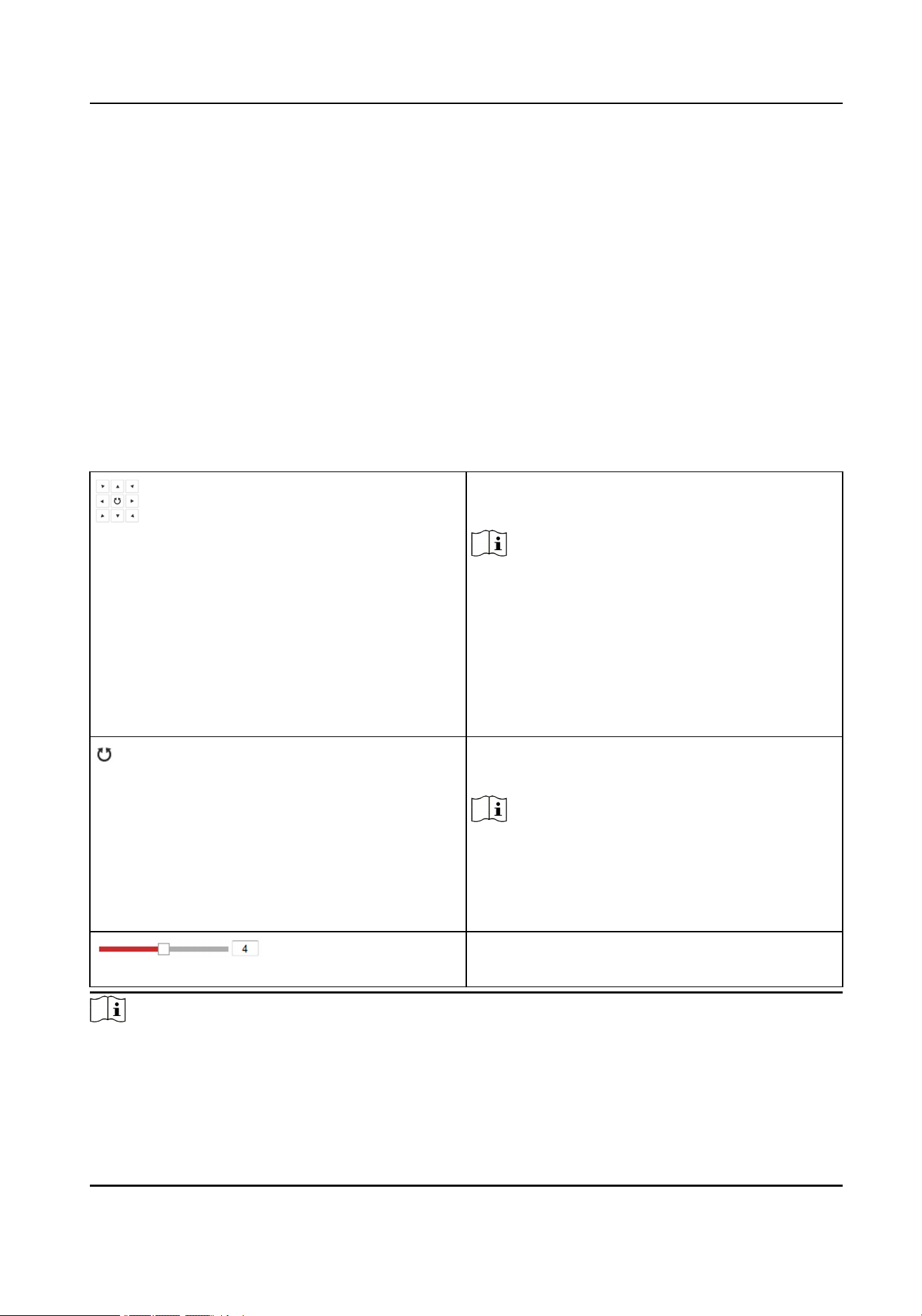
Chapter 10 PTZ
PTZ is an abbreviation for pan, tilt, and zoom. It means the movement options of the
camera.
10.1 PTZ Control
In live view interface, you can use the PTZ control buttons to control the device panning,
tilting, and zooming.
PTZ Control Panel
Click and hold the directional button to pan/
tilt the device.
Note
●
You can set
Keyboard Control Speed in
Conguration > PTZ > Basic Settings .
The speed of pan/tilt movement in live
view is based on this speed level.
●
You can set Max. Tilt-angle in
Conguration > PTZ > Basic Settings to
limit tilt movement range.
Click the button, then the device keeps
panning.
Note
You can set
Auto Scan Speed in
Conguration > PTZ > Basic Settings . The
higher the value you set, the faster the
device pans.
Drag the slider to adjust the speed of pan/
tilt movement.
Note
●
You can set Manual Control Speed in Conguration > PTZ > Basic Settings .
Thermal & Optical Bi-spectrum PTZ Network Camera User Manual
50

Compatible The control speed is same as Keyboard
Control Speed.
Pedestrian Choose Pedestrian when you monitor the
pedestrians.
Non-motor Vehicle Choose Non-motor Vehicle when you
monitor the non-motor vehicles.
Motor Vehicle Choose Motor Vehicle when you monitor
the motor vehicles.
Auto You are recommended to set it as Auto
when the application scene of the speed
dome is complicated.
●
To avoid blurred image resulted from fast zoom, you can check Enable Proportional Pan
in Conguration > PTZ > Basic Settings . If you enable this function, the pan/tilt speed
change according to the amount of zoom. When there is a large amount of zoom, the
pan/tilt speed will be slower for keeping the image from moving too fast on the live view
image.
Zoom in/out
Click the button, and the lens zooms in.
Click the button, and the lens zooms out.
Note
●
You can set Zooming Speed in Conguration > PTZ > Basic Settings . The higher the
value is, the faster the zooming speed is.
●
You can set Zoom Limit in Conguration > Image > Display Settings > Other to limit the
maximum value of the total zoom (digital zoom and optical zoom).
●
You can set Synchronized Zoom in Conguration > PTZ > Basic Settings to synchronize
the zoom settings in the optical channel and the thermal channel.
Focus
Click the button, then the lens focuses near
and the object nearby gets clear.
Click the button, then the lens focuses far
and the object far away gets clear.
Thermal & Optical Bi-spectrum PTZ Network Camera User Manual
51

Iris
When the image is too dark, click the button
to enlarge the iris.
When the image is too bright, click the
button to stop down the iris.
10.2 Set Preset
A preset is a predened image position. For the dened preset, you can call the preset No.
to view the position.
Steps
1.
Click to show the setting panel, and click .
2.
Use the PTZ control buttons to move the lens to the desired position.
3.
Select a preset number from the preset list, and click to nish the setting.
Note
Some presets are predened with special command. You can only call them but not
congure them.
4.
Repeat the steps above to set multiple presets.
Click the button to call the preset.
Click the button to delete the preset.
Note
You can delete all presets in Conguration > PTZ > Clear Cong . Click Clear All Presets,
and click Save.
What to do next
Go to Conguration > PTZ > Basic Settings to set preset freezing and preset speed.
After enabling preset freezing, the live image switches directly from one preset to another,
without showing the areas between these two scenes. It also guarantees the masked area
will not be seen when the device is moving.
10.2.1 Special Presets
You can call the following presets with special demands to enable corresponding
functions.
Thermal & Optical Bi-spectrum PTZ Network Camera User Manual
52

Preset No. Function Preset No. Function
33 Auto Flip 92 Set manual limits
34 Back to origin 93 Save manual limits
35 Call patrol 1 94 Remote restart
36 Call patrol 2 95 Call OSD menu
37 Call patrol 3 96 Stop a scan
38 Call patrol 4 97 Start random scan
39 Day mode 98 Start frame scan
40 Night mode 99 Start auto scan
41 Call pattern 1 100 Start tilt scan
42 Call pattern 2 101 Start panorama scan
43 Call pattern 3 102 Call patrol 5
44 Call pattern 4 103 Call patrol 6
45 One-touch patrol 104 Call patrol 7
46 Call area scan 105 Call patrol 8
47 Call area scan 1
Note
Not all models support the presets above. Please take the actual product for reference.
10.3 Set Patrol Scan
Patrol scan is a function to automatically move among multiple presets.
Before You Start
Note
This function is only supported by certain models.
Make sure that you have dened more than one presets. See
Set Preset
for detailed
conguration.
Steps
1.
Click to show the setting panel, and click to enter patrol setting interface.
2.
Select a patrol number from the list and click .
3.
Click to add presets.
Thermal & Optical Bi-spectrum PTZ Network Camera User Manual
53

Preset
Select predened preset.
Speed
Set the speed of moving from one preset to another.
Time
It is the duration staying on one patrol point.
Delete the presets in patrol.
Adjust the preset order.
Note
A patrol can be congured with 32 presets at most, and 2 presets at least.
4.
Click OK to nish a patrol setting.
5.
Repeat the steps above to congure multiple patrols.
6.
Operate patrols.
Call the patrol.
Stop patroling.
Delete the patrol.
Set the patrol.
Note
You can delete all patrols in Conguration > PTZ > Clear Cong . Click Clear All Patrols,
and click Save.
10.3.1 Set One-Touch Patrol
The device automatically adds presets to one patrol path and starts patrol scan.
Steps
1.
Set two or more presets except special presets. For setting presets, refer to
Set Preset
.
The device will automatically add presets to patrol path No.8.
2.
Choose one of the following methods to enable the function.
-
Click
.
-
Call patrol path No.8.
-
Select and call preset No.45.
10.4 Set Pattern Scan
The device can move as the recorded pattern.
Thermal & Optical Bi-spectrum PTZ Network Camera User Manual
54

Steps
Note
This function is only supported by certain models.
1.
Click to show the PTZ control panel, and click .
2.
Select one pattern scan path that needs to be set.
3.
Click to start recording pattern scan.
4.
Click PTZ control buttons as demands.
Note
Recording stops when the space for pattern scan is 0%.
5.
Click to complete one pattern scan path settings.
6.
Click to call pattern scan.
Stop pattern scan.
Reset pattern scan path.
Delete the selected pattern scan.
Note
If you need to delete all the pattern scans, go to Conguration > PTZ > Clear Cong , and
check Clear All Patterns, and click Save.
10.5 Set Linear Scan
The device can perform auto scan in setting area for re source detection.
Steps
1.
Go to Conguration > PTZ > Linear Scan .
2.
Select the camera channel.
3.
Zoom in and zoom out the camera to the appropriate zoom ratio, and click Save Ratio.
Note
Click Enable Saved Ratio to set the camera to the saved zoom ratio.
4.
Check Enter Area Settings.
5.
Set the left/right/up/down limits with the PTZ control panel, and click
to conrm
settings.
6.
Optional: Click Clear to delete the saved scan area.
7.
Click Save.
8.
Click Call Linear Scan to start linear scan, and click Stop Linear Scan to stop linear scan.
Thermal & Optical Bi-spectrum PTZ Network Camera User Manual
55

Note
When setting the linear scan area, make sure the target area is both included in the
optical channel and the thermal channel.
10.6 Set Limit
The device can only move within the limited range.
Steps
1.
Go to Conguration > PTZ > Limit .
2.
Select Limit Type.
Manual Stops
It refers to the movement range limit when you control the device manually.
Scan Stops
It refers to the movement range limit when the device scans automatically.
Note
Scan limit is only supported by the device that has scan function.
3.
Click Set and set limits according to the prompt on the live image.
4.
Optional: Click Clear to clear the limit settings of the selected mode.
5.
Click Save.
6.
Check Enable Limit.
Note
If you need to cancel all the set patrol paths, go to Conguration > PTZ > Clear Cong ,
select Clear All PTZ Limited, and click Save.
Result
The device can only move within the set region after saving the settings.
10.7 Set Initial Position
Initial position refers to the relative initial position of the device azimuth. You can set the
initial position if you need to select one point in the scene as the base point.
Steps
1.
Go to Conguration > PTZ > Initial Position .
2.
Move the device to the needed position by manually controlling the PTZ control buttons.
3.
Click Set to save the information of initial position.
Call The device moves to the set initial position.
Thermal & Optical Bi-spectrum PTZ Network Camera User Manual
56

Clear Clear the set initial position.
10.8 Set Park Action
You can set the device to perform an action (for example, preset or patrol) or return to a
position after a period of inactivity (park time).
Before You Start
Set the action type rst. For example, if you want to select patrol as park action, you should
set the patrol. See
Set Patrol Scan
for details.
Steps
1.
Go to Conguration > PTZ > Park Action .
2.
Check Enable Park Action.
3.
Set Park Time: the inactive time before the device starts park action.
4.
Select Action Type according to your needs.
Note
The VCA Type varies according to different action types.
5.
Select an Action Type ID, if you select patrol or preset as action type.
When the action type is patrol, action type ID stands for patrol No. When the action type
is preset, action type ID stands for preset No.
6.
Click Save.
10.9 Set Privacy Mask
Privacy masks cover certain areas on the live image to protect personal privacy from being
live viewed and recorded.
Steps
1.
Go to Conguration > PTZ > Privacy Mask .
2.
Select a channel.
3.
Adjust the live image to the target scene via PTZ control buttons.
4.
Draw the area.
Draw Area Click Draw Area, and click on the live view
image to determine the boundary of the
mask.
Stop Drawing Click Stop Drawing after drawing the mask.
5.
Click Add.
It is listed in Privacy Mask List.
Thermal & Optical Bi-spectrum PTZ Network Camera User Manual
57

6.
Edit Name, Type, and Active Zoom Ratio on your demand.
Active Zoom Ratio
When the actual zoom ratio is less than the set active zoom ratio, the set area cannot
be covered. When the actual zoom ratio is greater than the set active zoom ratio, the
privacy mask is valid. The maximum value of active zoom ratio depends on the
camera module.
Note
Active zoom ratio is only supported for the PTZ channel.
7.
Repeat the steps above to set other privacy masks.
8.
Check Enable Privacy Masks.
10.10 Set Scheduled Tasks
You can set the device to perform a certain task during a certain period.
Steps
1.
Go to Conguration > PTZ > Scheduled Tasks .
2.
Check Enable Scheduled Task.
3.
Select the task type from the drop-down list and draw a time bar on the schedule table.
4.
Click the set time bar and set the action ID and smart event or VCA type.
Note
Not all task types support the settings of action ID and smart event or VCA function.
Please take the actual product for reference.
5.
Repeat step 3 and step 4 to set more than one scheduled tasks.
6.
Set Park Time. During the set task period, if you operate the device manually, the
scheduled task will be suspended. When the manual operation is over, the device will
continue to perform the scheduled task after the set park time.
Note
Up to 30 time periods can be congured per day.
7.
Click Save.
Note
If you want to clear all scheduled tasks, go to Conguration > PTZ > Clear Cong , check
Clear All Scheduled Tasks, and click Save.
Thermal & Optical Bi-spectrum PTZ Network Camera User Manual
58

10.11 Set Combined Path
It offers the option to add multiple types of VCA scanning tasks to one combination path.
Setting the combined path as a scheduled task or a park action is convenient to manage
multiple VCA functions in different circumstances.
Before You Start
Note
This function is only supported by certain models.
Finish setting the desired actions (Linear Scan and Patrol are available) and VCA functions
(Fire Detection is available). See
Set Linear Scan
,
Set Patrol Scan
, and
Fire and Smoke
Detection
for conguration instructions.
Steps
1.
Go to Conguration > PTZ > Combined Path .
2.
Select a channel.
3.
Select a path number from the drop-down list.
Up to 4 paths are available.
4.
Click Add, and set the action type, action No. and VCA type for the added action.
Up to 10 actions can be added to one path.
You can click
ON to manually call the path and OFF to stop it.
5.
Click Save.
What to do next
Set the combined path in park action (see
Set Park Action
) or scheduled task (see
Set
Scheduled Tasks
).
10.12 Set Device Position
Before You Start
Go to Conguration > PTZ > Basic Settings > PTZ OSD to enable PT Status display.
Steps
1.
Go to the setting page: Conguration > PTZ > Position Settings .
2.
Select a PT Mode.
Manual Use a direction indicating device to determine the North at the device
location, and set the North for the device. For details, see
Set Manual
Compass
.
Auto For the device that has built-in e-compass, the compass can automatically
tell the north direction for the device. For details, see
Set Auto Compass
.
Thermal & Optical Bi-spectrum PTZ Network Camera User Manual
59

3.
Optional: Check Display Position Diagram to display the position diagram on the live
view.
4.
Set Vandal-proof alarm.
After enabling the function, the device triggers alarms once its position changes
because of shock or vandalism.
Sensitivity
The higher the value is, the easier the alarm will be triggered.
Upload Vandal-proof Alarm
The device uploads the alarm information when the alarm is triggered.
5.
Get the device location information in advance, and input the longitude and latitude of
the device manually.
6.
Click Save.
What to do next
If you lost direction when operating the device, you can click Point to North to call the
north position that is saved in the device.
10.12.1 Set Manual Compass
Use a direction indicating device to determine the North at the device location, and set the
North for the device.
Before You Start
Use a direction indicating device to determine the north at the device location.
Steps
1.
Select the PT Mode as Manual.
2.
Adjust the tilt position of the device to 0 by controlling the up arrow and down arrow on
the PTZ panel.
3.
Adjust the pan position to show the live view of the north direction by controlling the left
arrow and right arrow on the PTZ panel.
4.
Click Set as North.
10.12.2 Set Auto Compass
For the device that has built-in e-compass, the compass can automatically tell the north
direction for the device.
Before You Start
Electromagnetic interference may affect the accuracy of the e-compass. Use manual
compass if electromagnetic interference occurs in the device installation environment.
Steps
1.
Select the PT Mode as Auto.
Thermal & Optical Bi-spectrum PTZ Network Camera User Manual
60

2.
Click Calibrate to synchronize the north of the device with that of the e-compass.
10.13 Set Power Off Memory
This function can resume the previous PTZ status of device after it restarting from a
power-off.
Steps
1.
Go to Conguration > PTZ > Basic Settings .
2.
Select Resume Time Point. When the device stays at one position for the set resume
time point or more, the position is saved as a memory point. The device returns to the
last memory point when it restarts.
3.
Click Save.
10.14 Set PTZ Priority
The function can set the PTZ priority of different signals.
Steps
1.
Go to Conguration > PTZ > Prioritize PTZ .
2.
Set the priority signal and delayed time.
Network
The network signal controls the device with priority.
RS-485
The RS-485 signal controls the device with priority.
Delay
It refers to the time interval of PTZ operation controlled by different signals. When the
operation with high priority is nished, the low priority signal controls the device after
the setting interval.
3.
Click Save.
10.15 Set Tracking Parameters
Adjust the motion parameters of the device for better target tracking performance.
Steps
1.
Go to VCA > Set Application > Smart Event > Advanced Settings .
2.
Optional: Check Tuning Mode.
Thermal & Optical Bi-spectrum PTZ Network Camera User Manual
61

Note
Tuning mode is to display the information that helps debugging the function. This mode
is reserved for technical support.
3.
Set the Tracking Duration.
The device stops tracking when it tracks a target uninterruptedly for the set duration.
4.
Set the zooming control and other tracking parameters.
Zooming Control
Two modes are available. Controlled by target frame or by tilt angle of the device.
By Tilt Angle
The device calculates the tracking zoom ratio automatically according to the tilt
angle of the device.
Note
The attitude of the device affects the accuracy of this zooming control mode. For
the model with a built-in gyroscope, try to calibrate the attitude if some zooming
problems happen during tracking. See
Set Device Position
for instructions.
By Target Frame
The tracked target has a virtual frame around. The device calculates a suitable
zoom ratio according to the frame and the set Tracking Zoom Ratio. Larger value
means bigger zoom ratio.
Wait to Stop Tracking If Low Validity
The validity is an internal parameter that helps judge whether the device should keep
tracking or not. This parameter is the waiting time level before the device stops
tracking when the validity is low. Larger value means longer waiting time.
Wait to Lower Tracking Speed If Low Validity
The validity is an internal parameter that helps judge whether the PTZ channel should
lower the tracking speed or not. This parameter is the waiting time level before the
device lowers the tracking speed when the validity is low. Larger value means longer
waiting time.
5.
Optional: Click Default to restore the smart tracking parameters to default settings.
6.
Click Save.
10.16 Set Smart Tracking
You can congure the function to link the camera with the radar for more accurate and
higher speed target detecting and tracking.
Steps
1.
Select the camera channel from the drop-down list.
Thermal & Optical Bi-spectrum PTZ Network Camera User Manual
62

2.
Set basic parameter, refer to
Set Basic Parameter
.
3.
Set zooming ratio, refer to
Set Zooming Ratio
.
4.
Set object distance calibration, refer to
Set Object Distance Calibration
.
5.
Set polling plan, refer to
Set Polling Plan
.
10.16.1 Set Basic Parameter
Congure basic parameters of the linkage tracking.
Steps
1.
Go to Smart Tracking > Basic Parameter .
2.
Check Enable Linkage Monitoring to enable the radar linkage tracking. The linkage radar
will send the target position to assist the camera in tracking.
3.
Set tracking parameters.
Detection Target
Select the type of detection target.
Installation Height
Input the installation height of the camera.
Track Timeout
Input the timeout duration of tracking. The camera will stop tracking if there is no
updated position information after this duration.
Linkage Restoring Time
Input the restoring duration of tracking. The camera will restore linkage tracking after
this duration if the tracking process has been interrupted by PTZ manual control or
presets calling.
4.
Check Enable Video Relay Tracking. When the specic target is detected by the camera
repeatedly, the radar tracking system will switch to the video tracking. The camera will
continuously track the target based on the video detection in Tracking Duration.
Note
You can go to Smart Tracking > Polling Plan to assign optical or thermal video detection.
5.
Check Capture and Upload. The camera will automatically capture pictures of the target
according to its position and focusing/zooming quality, and then upload the pictures.
Note
For the camera that has not captured the target pictures, it will automatically capture
one target picture and upload if it receives the radar message to switch tracking targets.
6.
Check Allow Manual Focusing. You can focus the camera manually during the tracking
and won't interrupt the process.
Thermal & Optical Bi-spectrum PTZ Network Camera User Manual
63

Note
●
Pan and tilt manual control is not recommended in linkage tracking, because it will
interrupt the process.
●
The camera might not capture and upload automatically if the focusing/zooming
value isn't set properly.
7.
Click Save.
10.16.2 Set Zooming Ratio
Set the automatic zooming ratio in different object distance ranges to view the moving
target in proper image size during the tracking process.
Steps
1.
Go to Smart Tracking > Zooming Ratio .
2.
Click Get Recommended Value. Input the detection information and click OK to get one
recommended zooming ratio.
3.
Click Manual Add to add more zooming ratios in different object distance ranges. Up to
20 ratios are supported.
4.
Optional: Select the zooming ratio and click Delete to delete.
5.
Click Save.
10.16.3 Set Object Distance Calibration
Set and calibrate the automatic zooming ratio and focusing value in specic object
distance to get better image quality in scenes of darkness and low temperature difference.
Before You Start
You should complete the tracking zooming ratio conguration before.
Steps
1.
Go to Smart Tracking > Object Distance Calibration .
2.
Select External Application or PTZ Calculation as the way to obtain the detected object
distance in tracking.
3.
Aim the device at the target that meets the distance requirements. Adjust the zooming
ratio to the maximum with the PTZ control panel, and adjust the focus until the target is
clear enough.
4.
Calibrate the value.
1)Click Add to add one set of calibration.
2)Enter the actual value of the object distance.
3)Click Search to refresh the focusing, zooming and temperature value.
4)Click Calibration to complete a set of calibration.
5.
Click View Location to quickly view the saved image position.
Thermal & Optical Bi-spectrum PTZ Network Camera User Manual
64

6.
Follow the steps 3~5 to add more calibration of the each object distance or adjust the
existing calibration.
Note
●
For optical channel, the minimum, medium, and maximum detection distance are
recommended to set as the actual object distance.
●
For thermal channel, the maximum detection distance is recommended to set as the
actual object distance.
7.
Optional: Select the calibration value and click Delete to delete.
8.
Click Save.
Note
You can check Enable Auto Focus and the camera will automatically focus again after
the calibrated focusing. The function may have impact on lens service life.
10.16.4 Set Polling Plan
Assign the optical or thermal arming schedule of tracking.
Steps
1.
Go to Smart Tracking > Polling Plan .
2.
Select Polling Mode.
Auto
In this mode, the device will implement the polling plan automatically.
Manual
In this mode, you can set the polling plan manually.
3.
Click Save.
Thermal & Optical Bi-spectrum PTZ Network Camera User Manual
65

Chapter 11 Live View
It introduces the live view parameters, function icons and transmission parameters
settings.
11.1 Live View Parameters
The supported functions vary depending on the model.
Note
For multichannel devices, select the desired channel rst before live view settings.
11.1.1 Window Division
●
refers to 1 × 1 window division.
●
refers to 2 × 2 window division.
●
refers to 3 × 3 window division.
●
refers to 4 × 4 window division.
11.1.2 Live View Stream Type
Select the live view stream type according to your needs. For the detailed information
about the stream type selection, refer to
Stream Type
.
11.1.3 Enable and Disable Live View
This function is used to quickly enable or disable live view of all channels.
●
Click to start live view of all channels.
●
Click to stop live view of all channels.
11.1.4 View Previous/Next Page
When the number of channels surpasses that of live view window division, this function
can switch live view among multiple channels.
Click
to switch live view among multiple channels.
Thermal & Optical Bi-spectrum PTZ Network Camera User Manual
66

11.1.5 Full Screen
This function is used to view the image in full screen mode.
Click to start full screen mode and press ESC button to exit.
11.1.6 Conduct Regional Focus
You can enable the function to focus on certain area.
Steps
1.
Click to enable regional focus.
2.
Drag the mouse on the live view to draw a rectangle as the desired focus area.
3.
Click to disable this function.
11.1.7 Light
Click to turn on or turn off the illuminator.
11.1.8 Operate Wiper
For the device that has a wiper, you can control the wiper via web browser.
Note
Wiper operation and settings vary on device models.
Steps
1.
Go to Conguration > PTZ > Wiper .
2.
Select a wiper mode.
One
Time
The wiper wipes one time when you click on live view page.
Cycle The wiper works on schedule at set wiping interval. Click on live view to
start wiping.
Duration
The schedule in which the wiper is ready to work.
Interval
The interval between two successive wiping actions.
Thermal & Optical Bi-spectrum PTZ Network Camera User Manual
67

Auto
Note
Auto mode is only available for device that supports rain-sensing auto
wiper.
In auto mode, the wiper works when rain drops on the window.
11.1.9 Lens Initialization
Lens initialization is used on the device equipped with motorized lens. The function can
reset lens when long time zoom or focus results in blurred image. This function varies
according to different models.
Manual Lens Initialization
Click to operate lens initialization.
Auto Lens Initialization
Go to Conguration > System > Maintenance > Lens Correction to enable this function.
You can set the arming schedule, and the device will correct lens automatically during
the congured time periods.
11.1.10 Track Manually
In live view, manually select a target for the device to track.
Note
The function may not be supported by certain device models.
Steps
1.
Click on the toolbar of the live view page.
2.
Click a moving object in the live image.
The device tracks the target and keeps it in the center of live view image.
11.1.11 Auxiliary Focus
Click
to realize automatic focus. This function is subject to the actual device model.
11.1.12 Quick Set Live View
It offers a quick setup of PTZ, display settings, OSD, and video/audio settings on live view
page.
Thermal & Optical Bi-spectrum PTZ Network Camera User Manual
68

Steps
1.
Click to show quick setup page.
2.
Set PTZ, display settings, OSD, and video/audio parameters.
-
For PTZ settings, see
Lens Parameters Adjustment
.
-
For display settings, see
Display Settings
.
-
For OSD settings, see
OSD
.
-
For audio and video settings, see
Video and Audio
.
Note
The function is only supported by certain models.
11.1.13 Lens Parameters Adjustment
It is used to adjust the lens focus, zoom and iris.
Zoom
●
Click
, and the lens zooms in.
●
Click , and the lens zooms out.
Focus
●
Click , then the lens focuses far and the distant object gets clear.
●
Click , then the lens focuses near and the nearby object gets clear.
PTZ Speed
●
Slide to adjust the speed of the pan/tilt movement.
Iris
●
When the image is too dark, click to enlarge the iris.
●
When the image is too bright, click to stop down the iris.
11.1.14 Conduct 3D Positioning
3D positioning is to relocate the selected area to the image center.
Steps
1.
Click to enable the function.
2.
Select a target area in live image.
-
Left click on a point on live image: the point is relocated to the center of the live
image. With no zooming in or out effect.
-
Hold and drag the mouse to a lower right position to frame an area on the live: the
framed area is zoomed in and relocated to the center of the live image.
Thermal & Optical Bi-spectrum PTZ Network Camera User Manual
69

-
Hold and drag the mouse to an upper left position to frame an area on the live: the
framed area is zoomed out and relocated to the center of the live image.
3.
Click the button again to turn off the function.
11.1.15 De-icing
Click
to perform manual de-Icing of the device.
11.1.16 Synchronize FOV
Click
to synchronize the FOV of optical lens and thermal lens.
11.2 Set Transmission Parameters
The live view image may be displayed abnormally according to the network conditions. In
different network environments, you can adjust the transmission parameters to solve the
problem.
Steps
1.
Go to Conguration > Local .
2.
Set the transmission parameters as required.
Protocol
TCP
TCP ensures complete delivery of streaming data and better video quality, yet the
real-time transmission will be affected. It is suitable for the stable network
environment.
UDP
UDP is suitable for the unstable network environment that does not demand high
video uency.
MULTICAST
MULTICAST is suitable for the situation that there are multiple clients. You should
set the multicast address for them before selection.
Note
For detailed information about multicast, refer to
Multicast
.
HTTP
HTTP is suitable for the situation that the third-party needs to get the stream from
the device.
Play Performance
Thermal & Optical Bi-spectrum PTZ Network Camera User Manual
70

Shortest Delay
The device takes the real-time video image as the priority over the video uency.
Balanced
The device ensures both the real-time video image and the uency.
Fluent
The device takes the video uency as the priority over teal-time. In poor network
environment, the device cannot ensures video uency even the uency is enabled.
Custom
You can set the frame rate manually. In poor network environment, you can reduce
the frame rate to get a uent live view. But the rule information may cannot display.
Auto Start Live View
●
Yes means the live view is started automatically. It requires a high performance
monitoring device and a stable network environment.
●
No means the live view should be started manually.
3.
Click OK.
Thermal & Optical Bi-spectrum PTZ Network Camera User Manual
71

Chapter 12 Video and Audio
This part introduces the conguration of video and audio related parameters.
12.1 Video Settings
This part introduces the settings of video parameters, such as, stream type, video
encoding, and resolution.
Go to setting page:
Conguration > Video/Audio > Video .
Note
For device with multiple camera channels, select a channel before other settings.
12.1.1 Stream Type
For device supports more than one stream, you can specify parameters for each stream
type.
Main Stream
The stream stands for the best stream performance the device supports. It usually
offers the best resolution and frame rate the device can do. But high resolution and
frame rate usually mean larger storage space and higher bandwidth requirements in
transmission.
Sub Stream
The stream usually offers comparatively low resolution options, which consumes less
bandwidth and storage space.
12.1.2 Video Type
Select the content (video and audio) that should be contained in the stream.
Video
Only video content is contained in the stream.
Video & Audio
Video content and audio content are contained in the composite stream.
Thermal & Optical Bi-spectrum PTZ Network Camera User Manual
72

12.1.3 Resolution
Select video resolution according to actual needs. Higher resolution requires higher
bandwidth and storage.
12.1.4 Bitrate Type and Max. Bitrate
Constant Bitrate
It means that the stream is compressed and transmitted at a comparatively xed
bitrate. The compression speed is fast, but mosaic may occur on the image.
Variable Bitrate
It means that the device automatically adjust the bitrate under the set Max. Bitrate. The
compression speed is slower than that of the constant bitrate. But it guarantees the
image quality of complex scenes.
12.1.5 Video Quality
When Bitrate Type is set as Variable, video quality is congurable. Select a video quality
according to actual needs. Note that higher video quality requires higher bandwidth.
12.1.6 Frame Rate
The frame rate is to describe the frequency at which the video stream is updated and it is
measured by frames per second (fps).
A higher frame rate is advantageous when there is movement in the video stream, as it
maintains image quality throughout. Note that higher frame rate requires higher bandwidth
and larger storage space.
12.1.7 Video Encoding
It stands for the compression standard the device adopts for video encoding.
Note
Available compression standards vary according to device models.
H.264
H.264, also known as MPEG-4 Part 10, Advanced Video Coding, is a compression
standard. Without compressing image quality, it increases compression ratio and reduces
the size of video le than MJPEG or MPEG-4 Part 2.
Thermal & Optical Bi-spectrum PTZ Network Camera User Manual
73

H.264+
H.264+ is an improved compression coding technology based on H.264. By enabling H.
264+, you can estimate the HDD consumption by its maximum average bitrate. Compared
to H.264, H.264+ reduces storage by up to 50% with the same maximum bitrate in most
scenes.
When H.264+ is enabled, Max. Average Bitrate is congurable. The device gives a
recommended max. average bitrate by default. You can adjust the parameter to a higher
value if the video quality is less satisfactory. Max. average bitrate should not be higher
than max. bitrate.
Note
When H.264+ is enabled, Video Quality, I Frame Interval, Prole and SVC are not
congurable.
H.265
H.265, also known as High Efciency Video Coding (HEVC) and MPEG-H Part 2, is a
compression standard. In comparison to H.264, it offers better video compression at the
same resolution, frame rate and image quality.
H.265+
H.265+ is an improved compression coding technology based on H.265. By enabling H.
265+, you can estimate the HDD consumption by its maximum average bitrate. Compared
to H.265, H.265+ reduces storage by up to 50% with the same maximum bitrate in most
scenes.
When H.265+ is enabled,
Max. Average Bitrate is congurable. The device gives a
recommended max. average bitrate by default. You can adjust the parameter to a higher
value if the video quality is less satisfactory. Max. average bitrate should not be higher
than max. bitrate.
Note
When H.265+ is enabled, Video Quality, I Frame Interval, Prole and SVC are not
congurable.
Prole
This function means that under the same bitrate, the more complex the prole is, the
higher the quality of the image is, and the requirement for network bandwidth is also
higher.
Thermal & Optical Bi-spectrum PTZ Network Camera User Manual
74

I-Frame Interval
I-frame interval denes the number of frames between 2 I-frames.
In H.264 and H.265, an I-frame, or intra frame, is a self-contained frame that can be
independently decoded without any reference to other images. An I-frame consumes more
bits than other frames. Thus, video with more I-frames, in other words, smaller I-frame
interval, generates more steady and reliable data bits while requiring more storage space.
SVC
Scalable Video Coding (SVC) is the name for the Annex G extension of the H.264 or H.265
video compression standard.
The objective of the SVC standardization has been to enable the encoding of a high-quality
video bitstream that contains one or more subset bitstreams that can themselves be
decoded with a complexity and reconstruction quality similar to that achieved using the
existing H.264 or H.265 design with the same quantity of data as in the subset bitstream.
The subset bitstream is derived by dropping packets from the larger bitstream.
SVC enables forward compatibility for older hardware: the same bitstream can be
consumed by basic hardware which can only decode a low-resolution subset, while more
advanced hardware will be able decode high quality video stream.
12.1.8 Smoothing
It refers to the smoothness of the stream. The higher value of the smoothing is, the better
uency of the stream will be, though, the video quality may not be so satisfactory. The
lower value of the smoothing is, the higher quality of the stream will be, though it may
appear not uent.
12.1.9 Display VCA Info
VCA information can be displayed by Player and Video.
Player
Player means the VCA info can be displayed by the dedicated player provided by the
manufacturer.
Video
Video means the VCA info can be displayed by any general video player.
Thermal & Optical Bi-spectrum PTZ Network Camera User Manual
75

12.2 Audio Settings
It is a function to set audio parameters such as audio encoding, environment noise
ltering.
Go to the audio settings page:
Conguration > Video/Audio > Audio .
12.2.1 Audio Input
If a built-in microphone or an external audio pick-up device is available, audio encoding,
audio input mode and input volume are congurable.
Audio Encoding
The device offers several compression standard. Select according to your need.
Audio Input
Select MicIn for the built-in microphone, and LineIn for external audio pick-up device.
Note
MicIn is only supported by certain models.
Input Volume
Adjust the volume of the audio input.
Environmental Noise Filter
Set it as OFF or ON. When the function is enabled, the noise in the environment can be
ltered to some extent.
12.2.2 Two-way Audio
It is used to realize the two-way audio function between the monitoring center and the
target in the monitoring screen.
Before You Start
●
Make sure the audio input device (pick-up or microphone) and audio output device
(speaker) connected to the device is working properly. Refer to specications of audio
input and output devices for device connection.
●
If the device has built-in microphone and speaker, two-way audio function can be
enabled directly.
Steps
1.
Click Live View.
2.
Click on the toolbar to enable two-way audio function of the camera.
3.
Click and select , move the slider to adjust the volume.
4.
Click , disable the two-way audio function.
Thermal & Optical Bi-spectrum PTZ Network Camera User Manual
76

12.3 Set ROI
ROI (Region of Interest) encoding helps to assign more encoding resource to the region of
interest, thus to increase the quality of the ROI whereas the background information is less
focused.
Before You Start
Please check the video coding type. ROI is supported when the video coding type is H.264
or H.265.
Steps
1.
Go to Conguration > Video/Audio > ROI .
2.
Check Enable.
3.
Select the channel No. according to your need.
4.
Select Stream Type.
5.
Select Region No. in Fixed Region to draw ROI region.
1)Click Draw Area.
2)Click and drag the mouse on the view screen to draw the xed region.
3)Click Stop Drawing.
Note
Select the xed region that needs to be adjusted and drag the mouse to adjust its
position.
6.
Input the Region Name and ROI Level.
7.
Click Save.
Note
The higher the ROI level is, the clearer the image of the detected region is.
8.
Optional: Select other region No. and repeat the above steps if you need to draw multiple
xed regions.
12.4 Metadata
Metadata is the raw data that the device collects before algorithm processing. It is often
used for the third party integration.
Go to
Conguration > Video/Audio > Metadata Settings to enable metadata uploading of
the desired function for the camera channels.
12.5 Display Settings
It offers the parameter settings to adjust image features.
Thermal & Optical Bi-spectrum PTZ Network Camera User Manual
77
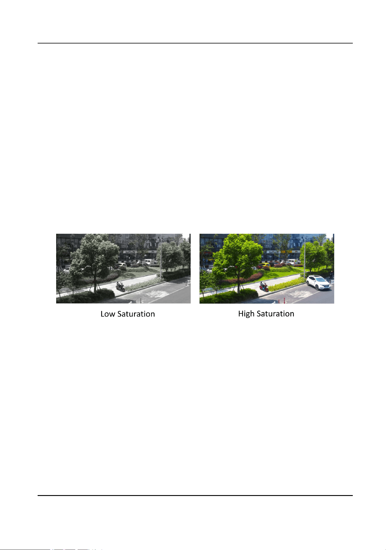
Go to Conguration > Image > Display Settings .
For device that supports multiple channels, display settings of each channel is required.
The settings for different channels may be different. This part introduces all possible
parameters among the channels.
Click Default to restore settings.
12.5.1 Scene Mode
There are several sets of image parameters predened for different installation
environments. Select a scene according to the actual installation environment to speed up
the display settings.
12.5.2 Image Adjustment
By adjusting the
Brightness, Saturation, Hue, Contrast and Sharpness, the image can be
best displayed.
Figure 12-1 Saturation
12.5.3 Image Adjustment (Thermal Channel)
You can optimize the image display effect of thermal channel by setting background
correction and manual correction.
Background Correction
Fully cover the lens with an object of uniform temperature in front of the lens, such as
foam board or paperboard. When you click DPC (Defective Pixel Correction), the device
will take the uniform object as the standard and optimize the image once.
Manual Correction
Click DPC (Defective Pixel Correction) to optimize the image once.
Thermal & Optical Bi-spectrum PTZ Network Camera User Manual
78

Note
It is a normal phenomenon that short video freezing might occur during the process of
Background Correction and Manual Correction.
Thermal AGC Mode
Choose the AGC mode according to different scenes to balance and improve the image
quality.
●
Histogram: Choose for scene with obvious WDR and high temperature difference, can
improve image contrast and enhance image (e.g., the scene contains both indoor and
outdoor scenes).
●
Linear: Choose for scene with low temperature difference and the target is not
obvious, can improve image contrast and enhance image (e.g., the bird in forest).
●
Self-Adaptive: Choose AGC mode automatically according to current scene.
12.5.4 Exposure Settings
Exposure is controlled by the combination of iris, shutter, and gain. You can adjust image
effect by setting exposure parameters.
Exposure Mode
Auto
The iris, shutter, and gain values are adjusted automatically.
You can limit the changing ranges of iris, shutter and gain by setting Max. Iris Limit,
Min. Iris Limit, Max. Shutter Limit, Min. Shutter Limit and Limit Gain for better
exposure effect.
Iris Priority
The value of iris needs to be adjusted manually. The shutter and gain values are
adjusted automatically according to the brightness of the environment.
You can limit the changing ranges of the shutter and gain by setting Max. Shutter
Limit, Min. Shutter Limit and Limit Gain for better exposure effect.
Shutter Priority
The value of shutter needs to be adjusted manually. The iris and gain values are
adjusted automatically according to the brightness of the environment.
You can limit the changing ranges of the iris by setting Max. Iris Limit, Min. Iris Limit
and Limit Gain for better exposure effect.
Manual
You need to set Iris, Shutter, and Gain manually.
Slow Shutter
Thermal & Optical Bi-spectrum PTZ Network Camera User Manual
79

The higher the slow shutter level is, the slower the shutter speed is. It ensures full
exposure in underexposure condition.
12.5.5 Day/Night Switch
Day/Night Switch function can provide color images in the day mode and turn on ll light in
the night mode. Switch mode is congurable.
Day
The image is always in color.
Night
The image is black/white or colorful and the supplement light will be enabled to ensure
clear live view image at night.
Auto
The camera switches between the day mode and the night mode according to the
illumination automatically.
Scheduled-Switch
Set the Start Time and the End Time to dene the duration for day mode.
Note
●
Day/Night Switch function varies according to models.
●
You can turn on the smart supplement light in auto, night, and schedule-switch modes
for better image effect.
12.5.6 Set Supplement Light
Steps
1.
Go to Conguration > Maintenance > System Service .
2.
Check Enable Supplement Light.
3.
Click Save.
Set Laser Parameters
You can enable the laser supplement and adjust the laser supplement angle to improve the
image effect.
Before You Start
Check Enable Supplement Light rst before you congure this function.
Steps
1.
Go to Conguration > System > Maintenance > System Service .
Thermal & Optical Bi-spectrum PTZ Network Camera User Manual
80

2.
Select Laser Optical Axis Adjustment from the drop-down list.
3.
Check Enable Laser Optical Axis Adjustment.
4.
Adjust the optical zoom ratio to the maximum value via PTZ control panel.
5.
Click the direction buttons to adjust the position of laser.
6.
Adjust the sensitivity. The higher the value is , the faster the cursor moves.
7.
Click Save when the laser point is in the center of live view.
8.
Go to Conguration > Image > Display Settings > Image Enhancement to set the laser
compensation region.
9.
Adjust the level of laser compensation.
Caution
The laser radiation emitted from the device can cause eye injuries, burning of skin or
inammable substances. Before enabling laser lighting supplement, make sure no
human or inammable substances are in front of the laser lens.
12.5.7 BLC
If you focus on an object against strong backlight, the object will be too dark to be seen
clearly. BLC (backlight compensation) compensates light to the object in the front to make
it clear. If BLC mode is set as Custom, you can draw a red rectangle on the live view image
as the BLC area.
12.5.8 WDR
The WDR (Wide Dynamic Range) function helps the camera provide clear images in
environment with strong illumination differences.
When there are both very bright and very dark areas simultaneously in the eld of view, you
can enable the WDR function and set the level. WDR automatically balances the brightness
level of the whole image and provides clear images with more details.
Note
When WDR is enabled, some other functions may be not supported. Refer to the actual
interface for details.
12.5.9 White Balance
White balance is the white rendition function of the camera. It is used to adjust the color
temperature according to the environment.
Thermal & Optical Bi-spectrum PTZ Network Camera User Manual
81
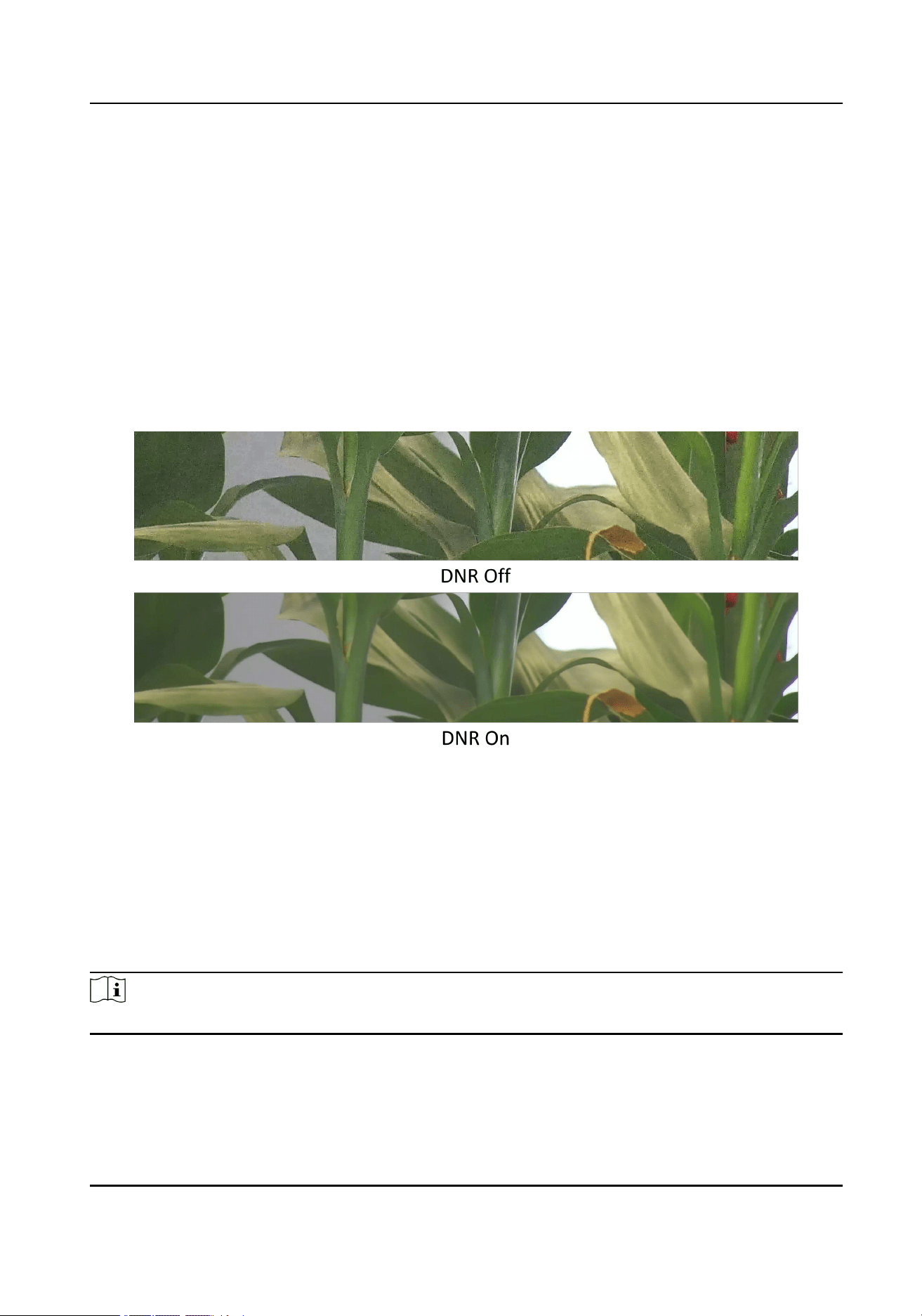
12.5.10 DNR
Digital Noise Reduction is used to reduce the image noise and improve the image quality.
Normal and Expert modes are selectable.
Normal
Set the DNR level to control the noise reduction degree. The higher level means stronger
reduction degree.
Expert
Set the DNR level for both space DNR and time DNR to control the noise reduction
degree. The higher level means stronger reduction degree.
Figure 12-2 DNR
12.5.11 Smart Noise Reduction
Smart Noise Reduction is a function that uses intelligent algorithms to automatically
remove noise, resulting in high-quality images.
Select the
Smart Noise Reduction as ON and conrm to restart the device to complete the
conguration.
Note
The function varies depending on different camera models.
Thermal & Optical Bi-spectrum PTZ Network Camera User Manual
82

12.5.12 Defog
You can enable the defog function when the environment is foggy and the image is misty.
It enhances the subtle details so that the image appears clearer.
Figure 12-3 Defog
12.5.13 EIS
Increase the stability of video image by using jitter compensation technology.
12.5.14 OIS
OIS (Optical Image Stabilization) reduces the effects of vibration in a video in order to
increase the stability of the video.
Normal
The camera enable OIS automatically, which can modify most unstable situations.
Expert
You can customize the level and sensitivity of OIS as needed.
12.5.15 Gamma Correction
Gamma correction can enhance the brightness and contrast of the display, making
brighter and more natural images.
12.5.16 Set Palette
You can select the palette mode to display the thermal grayscale image to colored image.
Steps
1.
Go to Conguration > Image > Display Settings .
2.
Select the thermal channel.
3.
Select a palette mode in Image Enhancement according to your need.
Thermal & Optical Bi-spectrum PTZ Network Camera User Manual
83

Result
The live view displays the image with palette.
12.5.17 Set Palette Range
The live view can display the palettes effect of the specied temperature range.
Select
Manual or Auto from By Temp. Range drop down list.
Auto
The device detects the max. temperature and min. temperature of the scene automatically
and display image of the whole scene with palettes.
Manual
In this mode, you can enter the temperature upper limit and lower limit manually. And the
live view shows the palettes effect of the desired temperature section more detailed.
12.5.18 DDE
Digital Detail Enhancement is used to adjust the details of the image.
OFF and Normal
modes are selectable.
OFF
Disable this function.
Normal
Set the DDE level to control the details of the image. The higher the level is, the more
details shows, but the higher the noise is.
12.5.19 Brightness Sudden Change
When the brightness of target and the background is hugely different (the temperature
difference of target and background is huge), the system reduces the difference for
viewing.
12.5.20 Target Enhancement
Enable this function to view the target clearer in environment of low temperature
difference.
Thermal & Optical Bi-spectrum PTZ Network Camera User Manual
84

12.5.21 Contrast Enhancement
This function can improve the palettes contract between high temperature and low
temperature areas, avoiding overexposure and over darkness of the image. OFF and On
modes are selectable.
12.5.22 Enhance Regional Image
You can select the desired area of image to improve the coding quality. The regional image
will be more detailed and clear.
Steps
1.
Go to Conguration > Image > Display Settings > Image Enhancement .
2.
Select the area of regional image enhancement. You can select OFF to disable this
function, or select Custom Area to draw a desired area.
A red rectangle shows on the display, in which the image quality is improved.
12.5.23 Mirror
When the live view image is the reverse of the actual scene, this function helps to display
the image normally.
Select the mirror mode as needed.
Note
The video recording will be shortly interrupted when the function is enabled.
12.5.24 Video Standard
Video standard is an ability of a video card or video display device that denes the amount
of colors that are shown and the resolution. The two most common video standard used
are NTSC and PAL. In NTSC, 30 frames are transmitted each second. Each frame is made
up of 525 individual scan lines. In PAL, 25 frames are transmitted each second. Each frame
is made up of 625 individual scan lines. Select video signal standard according to the
video system in your country/region.
12.5.25 Digital Zoom
You can zoom in the image. The larger the zoom size is, the more blurred the image is.
Thermal & Optical Bi-spectrum PTZ Network Camera User Manual
85

12.5.26 Zoom Limit
You can set a certain value to limit the maximum value of zooming.
12.5.27 Local Video Output
If the device is equipped with video output interfaces, such as BNC, CVBS, HDMI, and SDI,
you can preview the live image directly by connecting the device to a monitor screen.
Select the output mode as ON/OFF to control the output.
12.6 OSD
You can customize OSD (On-screen Display) information such as device name, time/date,
font, color, and text overlay displayed on video stream.
Go to OSD setting page:
Conguration > Image > OSD Settings .
Select a channel.
Set the corresponding parameters, and click Save to take effect.
Character Set
Select character set for displayed information. If Korean is required to display on screen,
select EUC-KR. Otherwise, select GBK.
Displayed Information
Set camera name, date, week, and their related display format.
Text Overlay
Set customized overlay text on image.
OSD Parameters
Set OSD parameters, such as
Display Mode, OSD Size, Font Color, and Alignment.
12.7 Overlay Picture
Overlay a customized picture on live view.
Before You Start
The picture to overlay has to be in BMP format with 24-bit, and the maximum picture size
is 128 × 128 pixel.
Steps
1.
Go to picture overlay setting page: Conguration > Image > Picture Overlay .
Thermal & Optical Bi-spectrum PTZ Network Camera User Manual
86

2.
Select a channel to overlay picture.
3.
Click Browse to select a picture, and click Upload.
The picture with a red rectangle will appear in live view after successfully uploading.
4.
Check Enable Picture Overlay.
5.
Drag the picture to adjust its position.
6.
Click Save.
12.8 Set Manual DPC (Defective Pixel Correction)
If the amount of defective pixels in the image is comparatively small and accurate
correction is needed, you can correct these pixels manually.
Steps
1.
Go to Conguration > Image > DPC .
2.
Select the thermal channel.
3.
Select manual mode.
4.
Click the defective pixel on the image, then a cursor shows on the live view.
5.
Click Up, Down, Left, Right to adjust the cursor position to the defective pixel position.
6.
Click , then click to correct defective pixel.
Note
If multiple defective pixels need to be corrected, click after locating a defective pixel.
Then after locating other pixels, click to correct them simultaneously.
7.
Optional: Click to cancel defective pixel correction.
12.9 Set Picture in Picture
You can overlay the images of two channels and view the image of two channels at the
same time.
Steps
1.
Select a channel number.
2.
Select the picture in picture mode.
Overlap Mode Partial image of thermal channel is displayed on the full screen of
optical channel. This mode is only supported in optical channel.
Details
Overlay Mode
The device displays the details of optical channel on thermal
channel. This mode is only supported in thermal channel.
3.
In Details Overlay Mode, set the Fusion Distance of the target. It is recommended to use
the default value.
4.
Click Save.
Thermal & Optical Bi-spectrum PTZ Network Camera User Manual
87

Note
Not all models support this function, take the actual product for reference.
12.10 VCA Rule Display Settings
The VCA rule display refers to the function that you can customize the displayed overlay
information of the VCA rule, which includes the font size and line and frame color.
You can go to
Conguration > Image > VCA Rule Display to select the desired font size, and
set the line and frame color.
12.11 Overlay Meteorological Data
Meteorological sensor collect and upload the data to the camera by the RS-485, and
display it on the optical image.
Steps
1.
Connect the meteorological sensor to the RS-485 interface of the device, until the
Sensor Connection Status changes Connected.
2.
Enable the following functions.
Display Meteorological Data
Checked and the meteorological data will be displayed on the optical image.
Upload Meteorological Data
Upload the data to the platform server.
Data Refresh Interval
Refresh the data once for every time interval.
3.
Check Meteorological elements that you need to display.
4.
Click Save.
Thermal & Optical Bi-spectrum PTZ Network Camera User Manual
88

Chapter 13 Video Recording and Picture Capture
This part introduces the operations of capturing video clips and snapshots, playback, and
downloading captured les.
13.1 Storage Settings
This part introduces the conguration of several common storage paths.
13.1.1 Set Memory Card
If you choose to store the les to memory card, make sure you insert and format the
memory card in advance.
Before You Start
Insert the memory card to the camera. For detailed installation, refer to
Quick Start Guide
of the camera.
Steps
1.
Go to storage management setting page: Conguration > Storage > Storage
Management > HDD Management .
2.
Select the memory card, and click Format to start initializing the memory card.
The Status of memory card turns to Normal from Uninitialized, which means the
memory card can be used normally.
3.
Optional: Dene the Quota of the memory card. Input the quota percentage for different
contents according to your need.
4.
Optional: Check to enable POS Information Storage, then the device will record the POS
information of reect light lter and forklift lter.
Note
The function is supported when your memory card capacity is 32 GB or above.
Formatting the memory card manually is required to reserve 16 GB for POS information.
5.
Click Save.
13.1.2 Set NAS
Take network server as network disk to store the record les, captured images, etc.
Before You Start
Get the IP address of the network disk rst.
Thermal & Optical Bi-spectrum PTZ Network Camera User Manual
89

Steps
1.
Go to NAS setting page: Conguration > Storage > Storage Management > Net HDD .
2.
Click HDD No. Select Mounting Type and set parameters for the disk.
Server Address
The IP address of the network disk.
File Path
The saving path of network disk les.
User Name and Password
The user name and password of the net HDD.
3.
Click Test to check whether the network disk is available.
4.
Click Save.
13.1.3 Set FTP
You can congure the FTP server to save images which are captured by events or a timed
snapshot task.
Before You Start
Get the FTP server address rst.
Steps
1.
Go to Conguration > Network > Advanced Settings > FTP .
2.
Congure FTP settings.
Server Address and Port
The FTP server address and corresponding port.
User Name and Password
The FTP user should have the permission to upload pictures.
If the FTP server supports picture uploading by anonymous users, you can check
Anonymous to hide your device information during uploading.
Directory Structure
The saving path of snapshots in the FTP server.
3.
Click Upload Picture to enable uploading snapshots to the FTP server.
4.
Click Test to verify the FTP server.
5.
Click Save.
13.1.4 Set Cloud Storage
It helps to upload the captured pictures and data to the cloud. The platform requests
picture directly from the cloud for picture and analysis. The function is only supported by
certain models.
Thermal & Optical Bi-spectrum PTZ Network Camera User Manual
90

Steps
Caution
If cloud storage is enabled, the pictures are stored in the cloud video manager
preferentially.
1.
Go to Conguration > Storage > Storage Management > Cloud Storage .
2.
Check Enable Cloud Storage.
3.
Set basic parameters.
Protocol Version The protocol version of the cloud video manager.
Server IP The IP address of the cloud video manager. It supports IPv4
address.
Serve Port The port of the cloud video manager. 6001 is the default port
and you are not recommended to edit it.
AccessKey The key to log in to the cloud video manager.
SecretKey The key to encrypt the data stored in the cloud video manager.
User Name and
Password
The user name and password of the cloud video manager.
Picture Storage
Pool ID
The ID of the picture storage region in the cloud video manager.
Make sure storage pool ID and the storage region ID are the
same.
4.
Click Test to test the congured settings.
5.
Click Save.
13.2 Video Recording
This part introduces the operations of manual and scheduled recording, playback, and
downloading recorded les.
13.2.1 Record Automatically
This function can record video automatically during congured time periods.
Before You Start
Select Trigger Recording in event settings for each record type except Continuous. See
Event and Alarm
for details.
Thermal & Optical Bi-spectrum PTZ Network Camera User Manual
91

Steps
Note
The function varies according to different models.
1.
Go to Conguration > Storage > Schedule Settings > Record Schedule .
2.
Select channel No.
3.
Check Enable.
4.
Select a record type.
Note
The record type is vary according to different models.
Continuous
The video will be recorded continuously according to the schedule.
Motion
When motion detection is enabled and trigger recording is selected as linkage
method, object movement is recorded.
Alarm
When alarm input is enabled and trigger recording is selected as linkage method, the
video is recorded after receiving alarm signal from external alarm input device.
Motion | Alarm
Video is recorded when motion is detected or alarm signal is received from the
external alarm input device.
Motion & Alarm
Video is recorded only when motion is detected and alarm signal is received from the
external alarm input device.
Event
The video is recorded when congured event is detected.
5.
Set schedule for the selected record type. Refer to
Set Arming Schedule
for the setting
operation.
6.
Click Advanced to set the advanced settings.
Overwrite
Enable Overwrite to overwrite the video records when the storage space is full.
Otherwise the camera cannot record new videos.
Pre-record
The time period you set to record before the scheduled time.
Post-record
The time period you set to stop recording after the scheduled time.
Thermal & Optical Bi-spectrum PTZ Network Camera User Manual
92

Stream Type
Select the stream type for recording.
Note
When you select the stream type with higher bitrate, the actual time of the pre-record
and post-record may be less than the set value.
Recording Expiration
The recordings are deleted when they exceed the expired time. The expired time is
congurable. Note that once the recordings are deleted, they can not be recovered.
7.
Click Save.
13.2.2 Record Manually
Steps
1.
Go to Conguration > Local .
2.
Set the Record File Size and saving path to for recorded les.
3.
Click Save.
4.
Click in the live view interface to start recording. Click to stop recording.
13.2.3 Playback and Download Video
You can search, playback and download the videos stored in the local storage or network
storage.
Steps
1.
Click Playback.
2.
Select channel No.
3.
Set search condition and click Search.
The matched video les showed on the timing bar.
4.
Click to play the video les.
-
Click
to clip video les.
-
Click
to play video les in full screen. Press ESC to exit full screen.
Note
Go to Conguration > Local , click Save clips to to change the saving path of clipped
video les.
5.
Click on the playback interface to download les.
1)Set search condition and click Search.
2)Select the video les and then click Download.
Thermal & Optical Bi-spectrum PTZ Network Camera User Manual
93

Note
Go to Conguration > Local , click Save downloaded les to to change the saving path
of downloaded video les.
13.3 Capture Conguration
The device can capture the pictures manually or automatically and save them in
congured saving path. You can view and download the snapshots.
13.3.1 Capture Automatically
This function can capture pictures automatically during congured time periods.
Before You Start
If event-triggered capture is required, you should congure related linkage methods in
event settings. Refer to
Event and Alarm
for event settings.
Steps
1.
Go to Conguration > Storage > Schedule Settings > Capture > Capture Parameters .
2.
Set the capture type.
Timing
Capture a picture at the congured time interval.
Event-Triggered
Capture a picture when an event is triggered.
3.
Set the Format, Resolution, Quality, Interval, and Capture Number.
4.
Refer to
Set Arming Schedule
for conguring schedule time.
5.
Click Save.
13.3.2 Capture Manually
Steps
1.
Go to Conguration > Local .
2.
Set the Image Format and saving path to for snapshots.
JPEG
The picture size of this format is comparatively small, which is better for network
transmission.
BMP
The picture is compressed with good quality.
3.
Click Save.
4.
Click near the live view or play back window to capture a picture manually.
Thermal & Optical Bi-spectrum PTZ Network Camera User Manual
94

13.3.3 View and Download Picture
You can search, view and download the pictures stored in the local storage or network
storage.
Steps
1.
Click Picture.
2.
Select channel No.
3.
Set search condition and click Search.
The matched pictures showed in the le list.
4.
Select the pictures then click Download to download them.
Note
Go to Conguration > Local , click Save snapshots when playback to change the saving
path of pictures.
Thermal & Optical Bi-spectrum PTZ Network Camera User Manual
95

Chapter 14 Network Settings
14.1 TCP/IP
TCP/IP settings must be properly congured before you operate the device over network.
IPv4 and IPv6 are both supported. Both versions can be congured simultaneously without
conicting to each other.
Go to
Conguration > Basic Conguration > Network > TCP/IP for parameter settings.
NIC Type
Select a NIC (Network Interface Card) type according to your network condition.
IPv4
Two IPv4 modes are available.
DHCP
The device automatically gets the IPv4 parameters from the network if you check
DHCP. The device IP address is changed after enabling the function. You can use
SADP to get the device IP address.
Note
The network that the device is connected to should support DHCP (Dynamic Host
Conguration Protocol).
Manual
You can set the device IPv4 parameters manually. Input IPv4 Address, IPv4 Subnet
Mask, and IPv4 Default Gateway, and click Test to see if the IP address is available.
IPv6
Three IPv6 modes are available.
Route Advertisement
The IPv6 address is generated by combining the route advertisement and the device
Mac address.
Note
Route advertisement mode requires the support from the router that the device is
connected to.
DHCP
The IPv6 address is assigned by the server, router or gateway.
Manual
Thermal & Optical Bi-spectrum PTZ Network Camera User Manual
96

Input IPv6 Address, IPv6 Subnet, IPv6 Default Gateway. Consult the network
administrator for required information.
MTU
It stands for maximum transmission unit. It is the size of the largest protocol data unit
that can be communicated in a single network layer transaction.
The valid value range of MTU is 1280 to 1500.
DNS
It stands for domain name server. It is required if you need to visit the device with
domain name. And it is also required for some applications (e.g., sending email). Set
Preferred DNS Server and Alternate DNS server properly if needed.
14.1.1 Multicast Discovery
Check the
Enable Multicast Discovery, and then the online network camera can be
automatically detected by client software via private multicast protocol in the LAN.
14.2 Port
The device port can be modied when the device cannot access the network due to port
conicts.
Caution
Do not modify the default port parameters at will, otherwise the device may be
inaccessible.
Go to Conguration > Network > Basic Settings > Port for port settings.
HTTP Port
It refers to the port through which the browser accesses the device. For example, when
the HTTP Port is modied to 81, you need to enter
http://192.168.1.64:81
in the browser
for login.
HTTPS Port
It refers to the port through which the browser accesses the device with certicate.
Certicate verication is required to ensure the secure access.
RTSP Port
It refers to the port of real-time streaming protocol.
SRTP Port
It refers to the port of secure real-time transport protocol.
Server Port
Thermal & Optical Bi-spectrum PTZ Network Camera User Manual
97

It refers to the port through which the client adds the device.
WebSocket Port
TCP-based full-duplex communication protocol port for plug-in free preview.
WebSockets Port
TCP-based full-duplex communication protocol port for plug-in free preview. Certicate
verication is required to ensure the secure access.
Note
●
Enhanced SDK Service Port, WebSocket Port, and WebSockets Port are only supported
by certain models.
●
For device models that support that function, go to Conguration > Network > Advanced
Settings > Network Service to enable it.
14.3 Port Mapping
By setting port mapping, you can access devices through the specied port.
Before You Start
When the ports in the device are the same as those of other devices in the network, refer to
Port
to modify the device ports.
Steps
1.
Go to Conguration > Network > Basic Settings > NAT .
2.
Select the port mapping mode.
Auto Port Mapping Refer to
Set Auto Port Mapping
for detailed information.
Manual Port Mapping Refer to
Set Manual Port Mapping
for detailed information.
3.
Click Save.
14.3.1 Set Auto Port Mapping
Steps
1.
Check Enable UPnP™, and choose a friendly name for the camera, or you can use the
default name.
2.
Select the port mapping mode to Auto.
3.
Click Save.
Note
UPnP™ function on the router should be enabled at the same time.
Thermal & Optical Bi-spectrum PTZ Network Camera User Manual
98

14.3.2 Set Manual Port Mapping
Steps
1.
Check Enable UPnP™, and choose a friendly name for the device, or you can use the
default name.
2.
Select the port mapping mode to Manual, and set the external port to be the same as the
internal port.
3.
Click Save.
What to do next
Go to the router port mapping settings interface and set the port number and IP address to
be the same as those on the device. For more information, refer to the router user manual.
14.4 Multicast
Multicast is group communication where data transmission is addressed to a group of
destination devices simultaneously.
Go to
Conguration > Network > Basic Settings > Multicast for the multicast settings.
For a device with more than one channel, multicast can be set independently for each
channel.
IP Address
It stands for the address of multicast host.
Stream Type
The stream type as the multicast source.
Video Port
The video port of the selected stream.
Audio Port
The audio port of the selected stream.
14.5 SNMP
You can set the SNMP network management protocol to get the alarm event and exception
messages in network transmission.
Before You Start
Before setting the SNMP, you should download the SNMP software and manage to receive
the device information via SNMP port.
Steps
1.
Go to the settings page: Conguration > Network > Advanced Settings > SNMP .
Thermal & Optical Bi-spectrum PTZ Network Camera User Manual
99

2.
Check Enable SNMPv1, Enable SNMP v2c or Enable SNMPv3.
Note
The SNMP version you select should be the same as that of the SNMP software.
And you also need to use the different version according to the security level required.
SNMP v1 is not secure and SNMP v2 requires password for access. And SNMP v3
provides encryption and if you use the third version, HTTPS protocol must be enabled.
3.
Congure the SNMP settings.
4.
Click Save.
14.6 Access to Device via Domain Name
You can use the Dynamic DNS (DDNS) for network access. The dynamic IP address of the
device can be mapped to a domain name resolution server to realize the network access
via domain name.
Before You Start
Registration on the DDNS server is required before conguring the DDNS settings of the
device.
Steps
1.
Refer to
TCP/IP
to set DNS parameters.
2.
Go to the DDNS settings page: Conguration > Network > Basic Settings > DDNS .
3.
Check Enable DDNS and select DDNS type.
DynDNS
Dynamic DNS server is used for domain name resolution.
NO-IP
NO-IP server is used for domain name resolution.
4.
Input the domain name information, and click Save.
5.
Check the device ports and complete port mapping. Refer to
Port
to check the device
port , and refer to
Port Mapping
for port mapping settings.
6.
Access the device.
By Browsers Enter the domain name in the browser address bar to access the
device.
By Client Software Add domain name to the client software. Refer to the client
manual for specic adding methods.
Thermal & Optical Bi-spectrum PTZ Network Camera User Manual
100

14.7 Access to Device via PPPoE Dial Up Connection
This device supports the PPPoE auto dial-up function. The device gets a public IP address
by ADSL dial-up after the device is connected to a modem. You need to congure the
PPPoE parameters of the device.
Steps
1.
Go to Conguration > Network > Basic Settings > PPPoE .
2.
Check Enable PPPoE.
3.
Set the PPPoE parameters.
Dynamic IP
After successful dial-up, the dynamic IP address of the WAN is displayed.
User Name
User name for dial-up network access.
Password
Password for dial-up network access.
Conrm
Input your dial-up password again.
4.
Click Save.
5.
Access the device.
By Browsers Enter the WAN dynamic IP address in the browser address bar to
access the device.
By Client
Software
Add the WAN dynamic IP address to the client software. Refer to
the client manual for details.
Note
The obtained IP address is dynamically assigned via PPPoE, so the IP address always
changes after restarting the camera. To solve the inconvenience of the dynamic IP, you
need to get a domain name from the DDNS provider (e.g., DynDns.com). Refer to
Access
to Device via Domain Name
for detail information.
14.8 Accessing via Mobile Client
Hik-Connect is an application for mobile devices. Using the App, you can view live image,
receive alarm notication and so on.
Note
Hik-Connect service should be supported by the camera.
Thermal & Optical Bi-spectrum PTZ Network Camera User Manual
101

14.8.1 Enable Hik-Connect Service on Camera
Hik-Connect service should be enabled on your camera before using the service.
You can enable the service through SADP software or Web browser.
Enable Hik-Connect Service via Web Browser
Follow the following steps to enable Hik-Connect Service via Web Browser.
Before You Start
You need to activate the camera before enabling the service.
Steps
1.
Access the camera via web browser.
2.
Enter platform access conguration interface. Conguration > Network > Advanced
Settings > Platform Access
3.
Select Hik-Connect as the Platform Access Mode.
4.
Check Enable.
5.
Click and read "Terms of Service" and "Privacy Policy" in pop-up window.
6.
Create a verication code or change the old verication code for the camera.
Note
The verication code is required when you add the camera to Hik-Connect service.
7.
Save the settings.
Enable Hik-Connect Service via SADP Software
This part introduce how to enable Hik-Connect service via SADP software of an activated
camera.
Steps
1.
Run SADP software.
2.
Select a camera and enter Modify Network Parameters page.
3.
Check Enable Hik-Connect.
4.
Create a verication code or change the old verication code.
Note
The verication code is required when you add the camera to Hik-Connect service.
5.
Click and read "Terms of Service" and "Privacy Policy".
6.
Conrm the settings.
Thermal & Optical Bi-spectrum PTZ Network Camera User Manual
102

14.8.2 Set Up Hik-Connect
Steps
1.
Download Hik-Connect from
https://www.hik-connect.com
and install it on your mobile
device.
2.
Start the application and register for a Hik-Connect user account.
3.
Log in after registration.
14.8.3 Add Camera to Hik-Connect
Steps
1.
Connect your mobile device to a Wi-Fi.
2.
Log into the Hik-Connect app.
3.
In the home page, tap "+" on the upper-right corner to add a camera.
4.
Scan the QR code on camera body or on the
Quick Start Guide
cover.
Note
If the QR code is missing or too blur to be recognized, you can also add the camera by
inputting the camera's serial number.
5.
Input the verication code of your camera.
Note
●
The required verication code is the code you create or change when you enable Hik-
Connect service on the camera.
●
If you forget the verication code, you can check the current verication code on
Platform Access conguration page via web browser.
6.
Tap Connect to a Network button in the popup interface.
7.
Choose Wired Connection or Wireless Connection according to your camera function.
Wireless
Connection
Input the Wi-Fi password that your mobile phone has connected to,
and tap Next to start the Wi-Fi connection process. (Locate the
camera within 3 meters from the router when setting up the Wi-Fi.)
Wired
Connection
Connect the camera to the router with a network cable and tap
Connected in the result interface.
Note
The router should be the same one which your mobile phone has connected to.
8.
Tap Add in the next interface to nish adding.
For detailed information, refer to the user manual of the Hik-Connect app.
Thermal & Optical Bi-spectrum PTZ Network Camera User Manual
103

14.9 Set ISUP
When the device is registered on ISUP platform (formerly called Ehome), you can visit and
manage the device, transmit data, and forward alarm information over public network.
Steps
1.
Go to Conguration > Network > Advanced Settings > Platform Access .
2.
Select ISUP as the platform access mode.
3.
Select Enable.
4.
Select a protocol version and input related parameters.
5.
Click Save.
Register status turns to Online when the function is correctly set.
14.10 Set Open Network Video Interface
If you need to access the device through Open Network Video Interface protocol, you can
congure the user settings to enhance the network security.
Steps
1.
Go to Conguration > Network > Advanced Settings > Integration Protocol .
2.
Check Enable Open Network Video Interface.
3.
Click Add to congure the Open Network Video Interface user.
Delete Delete the selected Open Network Video Interface user.
Modify Modify the selected Open Network Video Interface user.
4.
Click Save.
5.
Optional: Repeat the steps above to add more Open Network Video Interface users.
14.11 Set Alarm Server
The device can send alarms to destination IP address or host name through HTTP, HTTPS,
or ISUP protocol. The destination IP address or host name should support HTTP, HTTP, or
ISUP data transmission.
Steps
1.
Go to Conguration > Network > Advanced Settings > Alarm Server .
2.
Enter Destination IP or Host Name, URL, and Port.
3.
Select Protocol.
Note
HTTP, HTTPS, and ISUP are selectable. It is recommended to use HTTPS, as it encrypts
the data transmission during communication.
Thermal & Optical Bi-spectrum PTZ Network Camera User Manual
104

4.
Click Test to check if the IP or host is available.
5.
Click Save.
14.12 Set Network Service
You can control the ON/OFF status of certain protocol as desired.
Steps
Note
This function varies according to different models.
1.
Go to Conguration > Network > Advanced Settings > Network Service .
2.
Set network service.
WebSocket & WebSockets
WebSocket or WebSockets protocol should be enabled if you use Google Chrome 57
and its above version or Mozilla Firefox 52 and its above version to visit the device.
Otherwise, live view, image capture, and digital zoom function cannot be used.
If the device uses HTTP, enable WebSocket.
If the device uses HTTPS, enable WebSockets.
TLS (Transport Layer Security)
The device offers TLS1.1 and TLS1.2. Enable one or more protocol versions
according to your need.
3.
Click Save.
14.13 Set SRTP
The Secure Real-time Transport Protocol (SRTP) is a Real-time Transport Protocol (RTP)
internet protocol, intended to provide encryption, message authentication and integrity,
and replay attack protection to the RTP data in both unicast and multicast applications.
Steps
1.
Go to Conguration > Network > Advanced Settings > SRTP .
2.
Select Server Certicate.
3.
Select Encrypted Algorithm.
4.
Click Save.
Note
Only certain device models support this function.
Thermal & Optical Bi-spectrum PTZ Network Camera User Manual
105

Chapter 15 System and Security
It introduces system maintenance, system settings and security management, and
explains how to congure relevant parameters.
15.1 View Device Information
You can view device information, such as Device No., Model, Serial No. and Firmware
Version.
Enter
Conguration > System > System Settings > Basic Information to view the device
information.
15.2 Search and Manage Log
Log helps locate and troubleshoot problems.
Steps
1.
Go to Conguration > System > Maintenance > Log .
2.
Set search conditions Major Type, Minor Type, Start Time, and End Time.
3.
Click Search.
The matched log les will be displayed on the log list.
4.
Optional: Click Export to save the log les in your computer.
15.3 Import and Export Conguration File
It helps speed up batch conguration on other devices with the same parameters.
Steps
1.
Export conguration le.
1)Go to Conguration > System > Maintenance > Upgrade & Maintenance .
2)Click Device Parameters and input the encryption password to export the current
conguration le.
3)Set the saving path to save the conguration le in local computer.
2.
Import conguration le.
1)Access the device that needs to be congured via web browser.
2)Click Browse to select the saved conguration le.
3)Input the encryption password you have set when exporting the conguration le.
4)Click Import.
Thermal & Optical Bi-spectrum PTZ Network Camera User Manual
106

15.4 Export Diagnose Information
Diagnose information includes running log, system information, hardware information.
Go to
Conguration > System > Maintenance > Upgrade & Maintenance , and click
Diagnose Information to export diagnose information of the device.
15.5 Reboot
You can restart the device via browser.
Go to
Conguration > System > Maintenance > Upgrade & Maintenance , and click Reboot.
15.6 Device Auto Maintenance
Set the auto maintenance schedule and the device will automatically restart on schedule,
which helps avoid problems such as network anomaly and outage during continuous
operation, etc.
Steps
1.
Go to Conguration > System > Maintenance > Upgrade & Maintenance .
2.
Check Enable Auto Maintenance.
3.
Read the prompt information and click OK.
4.
Select the date and time when the device automatically restart.
5.
Click Save.
Note
This function is only available for Administrator.
15.7 Restore and Default
Restore and Default helps restore the device parameters to the default settings.
Steps
1.
Go to Conguration > System > Maintenance > Upgrade & Maintenance .
2.
Click Restore or Default according to your needs.
Restore Reset device parameters, except user information, IP parameters and video
format to the default settings.
Default Reset all the parameters to the factory default.
Thermal & Optical Bi-spectrum PTZ Network Camera User Manual
107

Note
Be careful when using this function. After resetting to the factory default, all
the parameters are reset to the default settings.
15.8 Upgrade
Before You Start
You need to obtain the correct upgrade package.
Caution
DO NOT disconnect power during the process, and the device restarts automatically after
upgrade.
Steps
1.
Go to Conguration > System > Maintenance > Upgrade & Maintenance .
2.
Choose one method to upgrade.
Firmware Locate the exact path of the upgrade le.
Firmware Directory Locate the directory which the upgrade le belongs to.
3.
Click Browse to select the upgrade le.
4.
Click Upgrade.
15.9 Set Electric Current Limit
This function can control the power supply current of the device.
Go to
Conguration > System > Maintenance > System Service , and select Electric Current
Limit type. You can limit the device current to 75% of full current or half the full current for
power saving control.
15.10 View Open Source Software License
Go to
Conguration > System > System Settings > About , and click View Licenses.
15.11 Time and Date
You can congure time and date of the device by conguring time zone, time
synchronization and Daylight Saving Time (DST).
Thermal & Optical Bi-spectrum PTZ Network Camera User Manual
108

15.11.1 Synchronize Time Manually
Steps
1.
Go to Conguration > System > System Settings > Time Settings .
2.
Select Time Zone.
3.
Click Manual Time Sync..
4.
Choose one time synchronization method.
-
Select
Set Time, and manually input or select date and time from the pop-up calendar.
-
Check
Sync. with computer time to synchronize the time of the device with that of the
local PC.
5.
Click Save.
15.11.2 Set NTP Server
You can use NTP server when accurate and reliable time source is required.
Before You Start
Set up a NTP server or obtain NTP server information.
Steps
1.
Go to Conguration > System > System Settings > Time Settings .
2.
Select Time Zone.
3.
Click NTP.
4.
Set Server Address, NTP Port and Interval.
Note
Server Address is NTP server IP address.
5.
Click Test to test server connection.
6.
Click Save.
15.11.3 Set DST
If the region where the device is located adopts Daylight Saving Time (DST), you can set
this function.
Steps
1.
Go to Conguration > System > System Settings > DST .
2.
Check Enable DST.
3.
Select Start Time, End Time and DST Bias.
4.
Click Save.
Thermal & Optical Bi-spectrum PTZ Network Camera User Manual
109

15.12 Set RS-232
RS-232 can be used to debug device or access peripheral device. RS-232 can realize
communication between the device and computer or terminal when the communication
distance is short.
Before You Start
Connect the device to computer or terminal with RS-232 cable.
Steps
1.
Go to Conguration > System > System Settings > RS-232 .
2.
Set RS-232 parameters to match the device with computer or terminal.
3.
Click Save.
15.13 Set RS-485
RS-485 is used to connect the device to external device. You can use RS-485 to transmit
the data between the device and the computer or terminal when the communication
distance is too long.
Before You Start
Connect the device and computer or terminal with RS-485 cable.
Steps
1.
Go to Conguration > System > System Settings > RS-485 .
2.
Set the RS-485 parameters.
Note
You should keep the parameters of the device and the computer or terminal the same.
3.
Click Save.
Note
The settings take effect only for the PTZ channel.
15.14 Set Same Unit
Set the same temperature unit and distance unit. When you enable this function, the unit
cannot be congured separately in other setting pages
Steps
1.
Go to Conguration > System > System Settings > Unit Settings .
2.
Check Use Same Unit.
3.
Set the temperature unit and distance unit.
Thermal & Optical Bi-spectrum PTZ Network Camera User Manual
110

4.
Click Save.
15.15 Set Visible Light Parameters
When the FOVs (Field of View) of the optical channel and thermal channel are not the
same, adjust the visible light optical axis to make sure the FOVs in the two channels are
the same.
Steps
1.
Go to Conguration > System > Maintenance > System Service .
2.
Select Visible Light Optical Axis Adjustment from the drop-down list.
3.
Check Enable Visible Light Optical Axis Adjustment.
4.
Adjust the optical zoom ratio to the maximum value via PTZ control panel.
5.
Click the direction buttons to adjust the position of the visible light optical axis.
6.
Adjust the sensitivity. The higher the value is, the faster the cursor moves.
7.
Click Save when the FOVs of the optical channel and thermal channel are the same.
Note
●
If the FOVs of the optical channel and thermal channel are not the same, functions
such as reect light lter and smoke auxiliary detection may be affected.
●
Please adjust the visible light optical axis under professional assistance.
15.16 Security
You can improve system security by setting security parameters.
15.16.1 Authentication
You can improve network access security by setting RTSP and WEB authentication.
Go to Conguration > System > Security > Authentication to choose authentication
protocol and method according to your needs.
RTSP Authentication
Digest and digest/basic are supported, which means authentication information is
needed when RTSP request is sent to the device. If you select digest/basic, it means the
device supports digest or basic authentication. If you select digest, the device only
supports digest authentication.
WEB Authentication
Digest and digest/basic are supported, which means authentication information is
needed when WEB request is sent to the device. If you select digest/basic, it means the
Thermal & Optical Bi-spectrum PTZ Network Camera User Manual
111

device supports digest or basic authentication. If you select digest, the device only
supports digest authentication.
Note
Refer to the specic content of protocol to view authentication requirements.
15.16.2 Security Audit Log
The security audit logs refer to the security operation logs. You can search and analyze the
security log les of the device so as to nd out the illegal intrusion and troubleshoot the
security events.
Security audit logs can be saved on device internal storage. The log will be saved every
half hour after device booting. Due to limited storage space, you can also save the logs on
a log server.
Search Security Audit Logs
You can search and analyze the security log les of the device so as to nd out the illegal
intrusion and troubleshoot the security events.
Steps
Note
This function is only supported by certain camera models.
1.
Go to Conguration > System > Maintenance > Security Audit Log .
2.
Select log types, Start Time, and End Time.
3.
Click Search.
The log les that match the search conditions will be displayed on the Log List.
4.
Optional: Click Export to save the log les to your computer.
Set Log Server
The log server should support syslog (RFC 3164) over TLS.
Before You Start
●
Install client and CA certicates before conguration. Refer to
Certicate Management
for detailed information.
●
Select certicates according to the requirement of the log server. If two-way
authentication is required, select the CA certicate and the client certicate. If one-way
authentication is required, select the CA certicate only.
Thermal & Optical Bi-spectrum PTZ Network Camera User Manual
112

Steps
1.
Check Enable Log Upload Server.
2.
Optional: Check Enable Encrypted Transmission if you want the log data to be encrypted.
3.
Input Log Server IP and Log Server Port.
4.
Optional: Select client certicate.
5.
Select CA certicate to the device.
6.
Click Test to test the settings.
7.
Click Save.
Certicate Management
It helps to manage the server/client certicates and CA certicate, and to send an alarm if
the certicates are close to expiry date, or are expired/abnormal.
Note
The function is only supported by certain device models.
15.16.3 Set IP Address Filter
IP address lter is a tool for access control. You can enable the IP address lter to allow or
forbid the visits from the certain IP addresses.
IP address refers to IPv4.
Steps
1.
Go to Conguration > System > Security > IP Address Filter .
2.
Check Enable IP Address Filter.
3.
Select the type of IP address lter.
Forbidden IP addresses in the list cannot access the device.
Allowed Only IP addresses in the list can access the device.
4.
Edit the IP address lter list.
Add Add a new IP address or IP address range to the list.
Modify Modify the selected IP address or IP address range in the list.
Delete Delete the selected IP address or IP address range in the list.
5.
Click Save.
15.16.4 Set MAC Address Filter
MAC address lter is a tool for access control. You can enable the MAC address lter to
allow or forbid the visits from the certain MAC addresses.
Thermal & Optical Bi-spectrum PTZ Network Camera User Manual
113

Steps
Note
MAC Address Filter is mutually exclusive with IP Address Filter.
1.
Go to Conguration > System > Security > MAC Address Filter .
2.
Check Enable MAC Address Filter.
3.
Select the type of MAC address lter.
Forbidden MAC addresses in the list cannot access the device.
Allowed Only MAC addresses in the list can access the device.
4.
Edit the MAC address lter list.
Add Add a new MAC address to the list.
Modify Modify the selected MAC address in the list.
Delete Delete the selected MAC address in the list.
5.
Click Save.
15.16.5 Certicate Management
It helps to manage the server/client certicates and CA certicate, and to send an alarm if
the certicates are close to expiry date, or are expired/abnormal.
Note
The function is only supported by certain device models.
Create Self-signed Certicate
Steps
1.
Click Create Self-signed Certicate.
2.
Follow the prompt to enter Certicate ID, Country/Region, Hostname/IP, Validity and
other parameters.
Note
The certicate ID should be digits or letters and be no more than 64 characters.
3.
Click OK.
4.
Optional: Click Export to export the certicate, or click Delete to delete the certicate to
recreate a certicate, or click Certicate Properties to view the certicate details.
Thermal & Optical Bi-spectrum PTZ Network Camera User Manual
114

Create Certicate Request
Before You Start
Select a self-signed certicate.
Steps
1.
Click Create Certicate Request.
2.
Enter the related information.
3.
Click OK.
Import Certicate
Steps
1.
Click Import.
2.
Click Create Certicate Request.
3.
Enter the Certicate ID.
4.
Click Browser to select the desired server/client certicate.
5.
Select the desired import method and enter the required information.
6.
Click OK.
7.
Optional: Click Export to export the certicate, or click Delete to delete the certicate to
recreate a certicate, or click Certicate Properties to view the certicate details.
Note
●
Up to 16 certicates are allowed.
●
If certain functions are using the certicate, it cannot be deleted.
●
You can view the functions that are using the certicate in the functions column.
●
You cannot create a certicate that has the same ID with that of the existing
certicate and import a certicate that has the same content with that of the existing
certicate.
Server Certicate/Client Certicate
Note
The device has default self-signed server/client certicate installed. The certicate ID is
default
.
Install CA Certicate
Steps
1.
Click Import.
Thermal & Optical Bi-spectrum PTZ Network Camera User Manual
115

2.
Enter the Certicate ID.
3.
Click Browser to select the desired server/client certicate.
4.
Select the desired import method and enter the required information.
5.
Click OK.
Note
Up to 16 certicates are allowed.
Enable Certicate Expiration Alarm
Steps
1.
Check Enable Certicate Expiration Alarm. If enabled, you will receive an email or the
camera links to the surveillance center that the certicate will expire soon, or is expired
or abnormal.
2.
Set the Remind Me Before Expiration (day), Alarm Frequency (day) and Detection Time
(hour).
Note
●
If you set the reminding day before expiration to 1, then the camera will remind you the
day before the expiration day. 1 to 30 days are available. Seven days is the default
reminding days.
●
If you set the reminding day before expiration to 1, and the detection time to 10:00,
and the certicate will expire in 9:00 the next day, the camera will remind you in 10:00
the rst day.
3.
Click Save.
15.16.6 Set SSH
SSH is a protocol to ensure security of remote login. This setting is reserved for
professional maintenance personnel only.
Steps
1.
Go to Conguration > System > Security > Security Service .
2.
Check Enable SSH.
3.
Click Save.
15.16.7 Set HTTPS
HTTPS is a network protocol that enables encrypted transmission and identity
authentication, which improves the security of remote access.
Thermal & Optical Bi-spectrum PTZ Network Camera User Manual
116

Steps
1.
Go to Conguration > Network > Advanced Settings > HTTPS .
2.
Check Enable .
3.
Optional: Check HTTPS Browsing to access the device only via HTTPS protocol.
4.
Click Delete to recreate and install certicate.
Create and install self-signed certicate Refer to
Create certicate request and install certicate Refer to
5.
Click Save.
15.16.8 Set QoS
QoS (Quality of Service) can help improve the network delay and network congestion by
setting the priority of data sending.
Note
QoS needs support from network device such as router and switch.
Steps
1.
Go to Conguration > Network > Advanced Conguration > QoS .
2.
Set Video/Audio DSCP, Alarm DSCP and Management DSCP.
Note
Network can identify the priority of data transmission. The bigger the DSCP value is, the
higher the priority is. You need to set the same value in router while conguration.
3.
Click Save.
15.16.9 Set IEEE 802.1X
IEEE 802.1x is a port-based network access control. It enhances the security level of the
LAN/WLAN. When devices connect to the network with IEEE 802.1x standard, the
authentication is needed.
Go to Conguration > Network > Advanced Settings > 802.1X , and enable the function.
Set Protocol and EAPOL Version according to router information.
Protocol
EAP-TLS and EAP-MD5 are selectable
EAP-MD5
If you use EAP-MD5, the authentication server must be congured. Register a user
name and password for 802.1X in the server in advance. Input the user name and
password for authentication.
Thermal & Optical Bi-spectrum PTZ Network Camera User Manual
117

EAP-TLS
If you use EAP-TLS, input Identify, Private Key Password, and upload CA Certicate,
User Certicate and Private Key.
EAPOL Version
The EAPOL version must be identical with that of the router or the switch.
15.17 User and Account
15.17.1 Set User Account and Permission
The administrator can add, modify, or delete other accounts, and grant different
permission to different user levels.
Caution
To increase security of using the device on the network, please change the password of
your account regularly. Changing the password every 3 months is recommended. If the
device is used in high-risk environment, it is recommended that the password should be
changed every month or week.
Steps
1.
Go to Conguration > System > User Management > User Management .
2.
Click Add. Enter User Name, select Level, and enter Password. Assign remote
permission to users based on needs.
Administrator
The administrator has the authority to all operations and can add users/operators and
assign permission.
User
Users can be assigned permission of viewing live video, setting parameters, and
changing their own passwords, but no permission for other operations.
Operator
Operators can be assigned all permission except for operations on the administrator
and creating accounts.
Modify Select a user and click Modify to change the password and permission.
Delete Select a user and click Delete.
Note
The administrator can add up to 31 user accounts.
3.
Click General to set the allowed number of multi-user simultaneous login.
Thermal & Optical Bi-spectrum PTZ Network Camera User Manual
118

Note
Only the administrator has the authority to the operation.
4.
Click OK.
15.17.2 Online Users
The information of users logging into the device is shown.
Go to Conguration > System > User Management > Online Users to view the list of online
users.
Thermal & Optical Bi-spectrum PTZ Network Camera User Manual
119

Chapter 16 Appendix
16.1 Common Material Emissivity Reference
Material Emissivity
Human Skin 0.98
Printed Circuit Board 0.91
Concrete 0.95
Ceramic 0.92
Rubber 0.95
Paint 0.93
Wood 0.85
Pitch 0.96
Brick 0.95
Sand 0.90
Soil 0.92
Cloth 0.98
Hard Paperboard 0.90
White Paper 0.90
Water 0.96
Thermal & Optical Bi-spectrum PTZ Network Camera User Manual
120

UD36092B